

Page 1

Industrial Automation Headquarters
Delta Electronics, Inc.
Taoyuan Technology Center
No.18, Xinglong Rd., Taoyuan City,
Taoyuan County 33068, Taiwan
TEL: 886-3-362-6301 / FAX: 886-3-371-6301
Asia
Delta Electronics (Jiangsu) Ltd.
Wujiang Plant 3
1688 Jiangxing East Road,
Wujiang Economic Development Zone
Wujiang City, Jiang Su Province,
People's Republic of China (Post code: 215200)
TEL: 86-512-6340-3008 / FAX: 86-769-6340-7290
Delta Greentech (China) Co., Ltd.
238 Min-Xia Road, Pudong District,
ShangHai, P.R.C.
Post code : 201209
TEL: 86-21-58635678 / FAX: 86-21-58630003
Delta Ultimate Integrated AC Servo Drive with
Excellent Performance
Delta Electronics (Japan), Inc.
Tokyo Ofce
2-1-14 Minato-ku Shibadaimon,
Tokyo 105-0012, Japan
TEL: 81-3-5733-1111 / FAX: 81-3-5733-1211
Delta Electronics (Korea), Inc.
1511, Byucksan Digital Valley 6-cha, Gasan-dong,
Geumcheon-gu, Seoul, Korea, 153-704
TEL: 82-2-515-5303 / FAX: 82-2-515-5302
Delta Electronics Int’l (S) Pte Ltd
4 Kaki Bukit Ave 1, #05-05, Singapore 417939
TEL: 65-6747-5155 / FAX: 65-6744-9228
Delta Electronics (India) Pvt. Ltd.
Plot No 43 Sector 35, HSIIDC
Gurgaon, PIN 122001, Haryana, India
TEL : 91-124-4874900 / FAX : 91-124-4874945
Americas
Delta Products Corporation (USA)
Raleigh Ofce
P.O. Box 12173,5101 Davis Drive,
Research Triangle Park, NC 27709, U.S.A.
TEL: 1-919-767-3800 / FAX: 1-919-767-8080
Delta Greentech (Brasil) S.A
Sao Paulo Ofce
Rua Itapeva, 26 - 3° andar Edicio Itapeva One-Bela Vista
01332-000-São Paulo-SP-Brazil
TEL: +55 11 3568-3855 / FAX: +55 11 3568-3865
Europe
Deltronics (The Netherlands) B.V.
Eindhoven Ofce
De Witbogt 15, 5652 AG Eindhoven, The Netherlands
TEL: 31-40-2592850 / FAX: 31-40-2592851
ASDA-M
Delta Ultimate Integrated
Series User Manual
AC Servo Drive with
Excellent Performance
ASDA-M
Series
User Manual
Via Polesine, 1/4
10020 Cambiano ( TO ) Italy
+39 011 9454523
www.e-comtech.it
info@e-comtech.it
*We reserve the right to change the information in this catalogue without prior notice.
V2.0
DELTA_
IA-ASDA_M_UM_EN_20141219
www.delta.com.tw/ia
Page 2

Preface
Thank you for purchasing ASDA-M. This user manual provides the related information of
ASDA-M series servo drives and ECMA series servo motors. This manual includes:
Installation and inspection of servo drive and servo motor
The configuration of servo drive
Procedures of trial run
Control function and adjustment methods of servo drive
Parameters
Communication protocol
Maintenance and inspections
Troubleshooting
This manual addresses personnel with the following qualifications:
Servo system designers
Installation or wiring personnel
Trial and tuning personnel
Maintenance and inspection personnel
Before using the product, please read through this manual carefully in order to ensure the
correct use of the product. In addition, please place this manual safely for quick reference
whenever is needed. Please follow the rules below if you have not finished reading this
manual yet.
No water, corrosive gas and inflammable gas are allowed in installation
environment.
Three-phase power is prohibited to connect to U, V and W connector when wiring.
It is possible to damage the servo drive.
Ground is a must.
Do not disconnect the servo drive, motor or change the wiring when connecting to
the power.
Be ensured that the emergency stop can be activated anytime before connecting to
the power and operation.
Do not touch the heat sink to avoid scald before connecting to the power and
operation.
If you have any enquiry , please contact the distri butors or DEALTA customer service center.
Revision December, 2014 i
Page 3
Preface ASDA-M
Safety Precautions
ASDA-M series is the high resolution and open type servo drive. It should be installed in a
shielded control box during operation. This servo drive uses precise feedback control and
the digital signal processor with high-speed calculation function to control the current output
which generated by IGBT so as to operate three-phase permanent magnet synchronous
motors (PMSM) and to achieve precise positioning.
ASDA-M is applicable on industrial application and is suggested to be installed in the
panel-board of the user manual. (Servo drives, wire rod and motors all should be installed
in the environment which complies with the minimum requirement of UL Level 1.)
Pay special attention to the following safety precautions anytime during inspection,
installation, wiring, operation and examination.
The symbol of danger, warning and stop represent:
It indicates the potential hazards. It is possible to cause severe injury or fatal
harm if not follow the instructions.
It indicates the potential hazards. It is possible to cause minor injury or lead to
serious damage of the product or even malfunction if not follow the instructions.
It indicates the absolute prohibited activity. It is possible to damage the product or
cannot be used due to malfunction if not follow the instructions.
Inspection
Please follow the instruction when using servo drive and servo motor, or it is
Installation
It is prohibited to expose the product with the environment which containing
Wiring
Please connect the ground terminal to class-3 ground system (under 100 Ω),
Do not connect the three-phase source to the motor output terminal U, V and
Please tighten the screws of the power and motor output terminal. Or it is
Please connect wiring according to the wire rod in order to prevent any
possible to cause fire or malfunction.
water, corrosive gas, inflammable gas, etc. Or it is possible to cause electric
shock or fire.
poor grounding may result in electric shock or fire.
W. Or it is possible to cause personnel injury or fire.
possible to cause fire.
danger.
ii Revision December, 2014
Page 4
ASDA-M Preface
Operation
Before the operation, please change the parameter setting value according to
the needs. If it is not adjusted to the correct setting value, it is possible to lead
to malfunction of the machine or the operation might out of control.
Before the machine starts to operate, please be ensured the emergency stop
can be activated anytime.
During the operation, it is prohibited to touch any rotating motor parts. Or it is
possible to cause personnel injury.
In order to prevent any accident, please separate the couplings and belts of
the machine and isolate them. Then conduct the initial trial run.
If users fail to operate the machine properly after the servo motor connects to
the equipments, it would cause the damage of the equipments and lead to the
personnel injury.
In order to prevent the danger, it is strongly recommended to check if the
motor can operate normally without load first. Then, operate the motor with
load.
Do not touch the heat sink of the servo drive. Or it is possible to cause scald
due to the high temperature.
Maintenance and Inspection
It is prohibited to touch the internal parts of the servo drive and servo motor.
Or it is possible to cause electric shock.
It is prohibited to disassemble the panel of the servo drive when turning on the
power. Or it is possible to cause electric shock.
Do not touch the ground terminal within 10 minutes after turning off the power .
Or the residual voltage may cause electric shock.
Do not disassemble the motor. Or it is possible to cause electric shock or
personnel injury.
Do not change the wiring when the power is on. Or it is possible to cause
electric shock or personnel injury.
Only the qualified electrical and electronics professionals can install, wire and
maintain the servo drive and servo motor.
Main Circuit Wiring
Do not put the power cable and the encoder cable in the same channel and
bond them together. Please separate the power cable and the encoder cable
for at least 30 centimeters (= 11.8 inches) when wiring.
Please use stranded wires and multi-core shielded-pair wires for the encoder
cables and encoder feedback cables. The maximum length of command input
cable is 3 meters (= 9.84 feet) and the maximum length of feedback cable is
20 meters (= 65.62 feet).
The high voltage might remain in the servo motor even when the power is off.
Do not touch the power terminal temporally (at least 10 minutes). Please
conduct the inspection not until the indicator light, CHARGE is off.
Revision December, 2014 iii
Page 5

Preface ASDA-M
Do not turn the power on and off too often. If continuous power on and off is
needed, please be ensured the interval is one minute at most.
Terminal Wiring of the Main Circuit
When wiring, please disassemble the terminal socket from the servo drive.
One terminal of the terminal socket for one electric wire only.
When inserting the electric wires, do not connect the conductor to the adjacent
wire.
Before connecting to the power, please inspect and be ensured the wiring is
correct.
NOTE
If there is any difference of each version, please refer to DELTA’s
website (http://www.delta.com.tw/industrialautomation/) for the latest
information.
iv
Revision December, 2014
Page 6

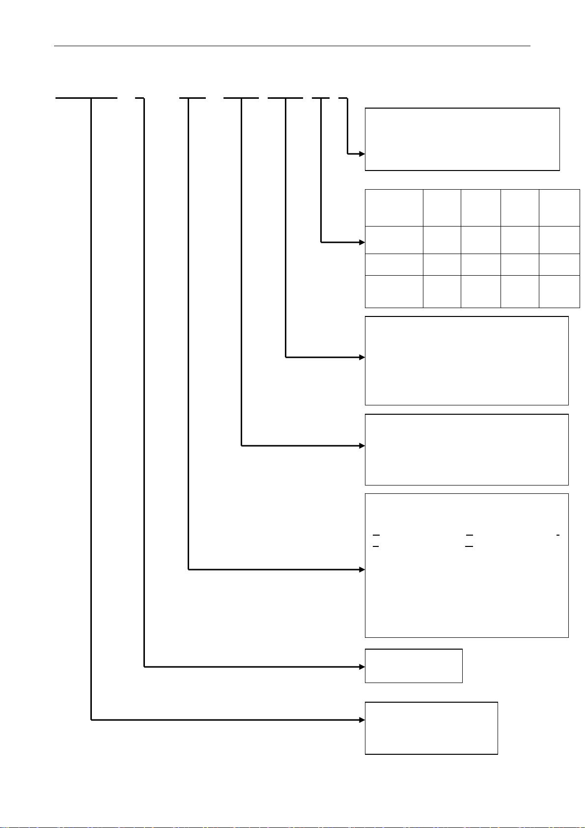
Table of Content
Chapter 1 Inspection and Model Explanation
1.1 Inspection ...................................................................................................... 1-1
1.2 Product Model .............................................................................................. 1-2
1.2.1 Nameplate Information ......................................................................... 1-2
1.2.2 Model Explanation ................................................................................ 1-3
1.3 Servo Drive and Corresponding Servo Motor ................................................ 1-5
1.4 Features of Servo Drive ................................................................................. 1-6
Chapter 2 Installation
2.1 Notes ............................................................................................................. 2-1
2.2 Ambient Conditions of Storage ...................................................................... 2-1
2.3 Ambient Conditions of Installation ................................................................. 2-2
2.4 Installation Direction and Space .................................................................... 2-3
2.5 Specification of Circuit Breaker and Fuse ...................................................... 2-5
2.6 EMI Filters Selection ...................................................................................... 2-5
2.7 Selection of Regenerative Resistor ............................................................... 2-8
Chapter 3 Wiring
3.1 Connection between Peripheral Devices and Main Power Circuit ................. 3-1
3.1.1 Wiring Diagram of Peripheral Devices ................................................... 3-1
Revision December, 2014
Page 7

Table of Content ASDA-M
3.1.2 Connectors and Terminals of the Servo Drive ....................................... 3-3
3.1.3 Wiring Method ....................................................................................... 3-5
3.1.4 Specification of Motor U, V, W Power Cable ......................................... 3-7
3.1.5 Specification of Connector of Encoder Cable ........................................ 3-9
3.1.6 Selection of Wire Rod ............................................................................ 3-12
3.2 Schematic Diagram of Servo System ............................................................ 3-14
3.3 I/O Signal (CN1) Connection ......................................................................... 3-15
3.3.1 I/O Signal (CN1) Connector Terminal Layout ....................................... 3-15
3.3.2 Explanation of I/O (CN1) Connector Signal .......................................... 3-17
3.3.3 Wiring Diagram (CN1) .......................................................................... 3-31
3.3.4 The Specified DI and DO Signal by the User ........................................ 3-40
3.4 CN2 Connector .............................................................................................. 3-41
3.5 Wiring of CN3 Connector ............................................................................... 3-44
3.5.1 Layout of CN3 Connector ..................................................................... 3-44
3.5.2 Connection between CN3 connector and Personal Computer ............. 3-45
3.6 CN4 Serial Connector (USB) ......................................................................... 3-46
3.7 CN5 Connector (Full-closed Loop) ................................................................ 3-47
3.8 CN6 Connector (CANopen) ........................................................................... 3-48
3.9 Standard Wiring Method ................................................................................ 3-50
3.9.1 Position (PT) Mode Standard Wiring .................................................. 3-50
3.9.2 Position (PR) Mode Standard Wiring .................................................. 3-51
3.9.3 Speed Mode Standard Wiring ............................................................. 3-52
3.9.4 Torque Mode Standard Wiring ............................................................ 3-53
Revision December, 2014
Page 8

ASDA-M Table of Content
3.9.5 CANopen Mode Standard Wiring ........................................................ 3-54
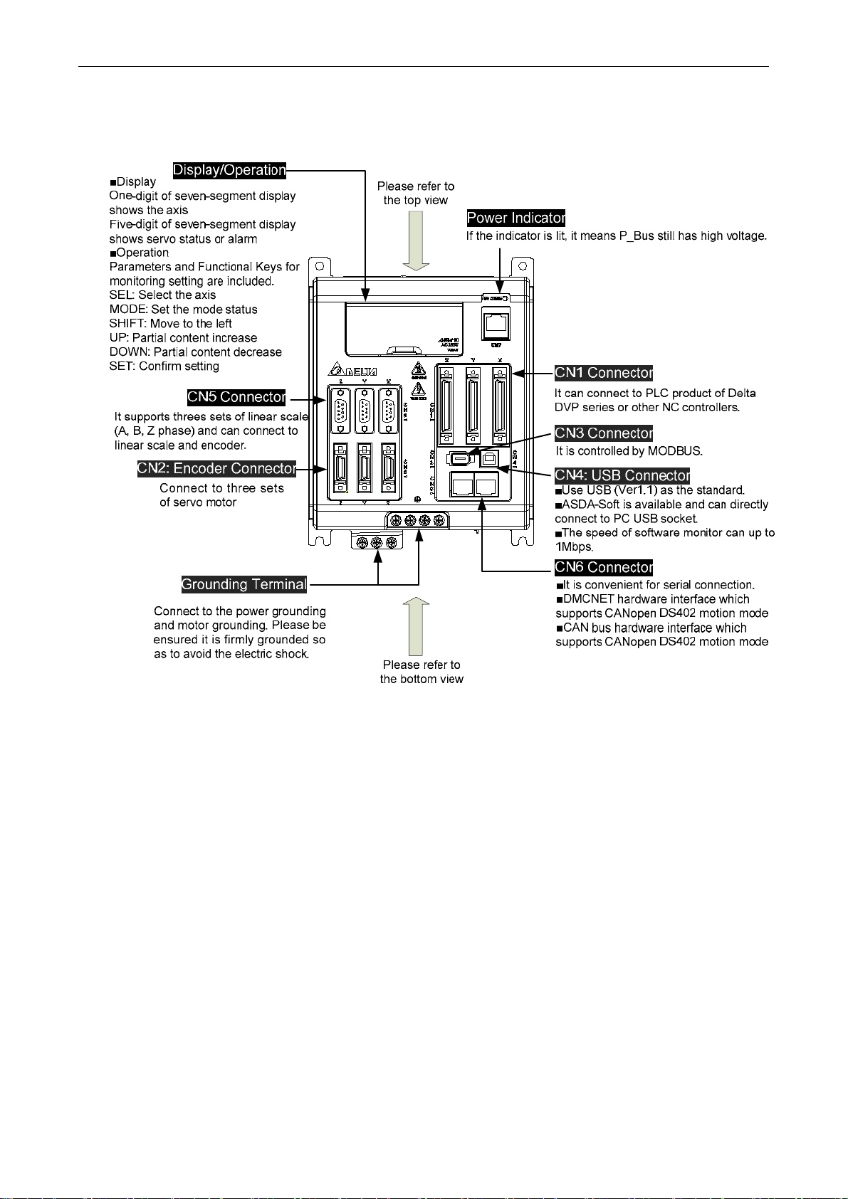
Chapter 4 Panel Display and Operation
4.1 Panel Description .......................................................................................... 4-1
4.2 Parameter Setting Procedure ........................................................................ 4-2
4.2.1 Axis Switching Procedure .................................................................... 4-2
4.2.2 Parameter Setting Procedure of Each Axis ......................................... 4-3
4.3 Status Display................................................................................................ 4-4
4.3.1 Setting Saved Display .......................................................................... 4-4
4.3.2 Decimal Point ....................................................................................... 4-4
4.3.3 Alarm Message ..................................................................................... 4-4
4.3.4 Positive and Negative Sign Setting ....................................................... 4-4
4.3.5 Monitor Display ..................................................................................... 4-5
4.4 General Function ........................................................................................... 4-8
4.4.1 Operation of Fault Record Display ........................................................ 4-8
4.4.2 JOG Mode ............................................................................................ 4-9
4.4.3 Forced Digital Output Operation ........................................................... 4-10
4.4.4 Digital Input Diagnosis Operation ......................................................... 4-11
4.4.5 Digital Output Diagnosis Operation ...................................................... 4-12
Chapter 5 Trial Operation and Tuning
5.1 Inspection without Load ................................................................................. 5-1
5.2 Apply Power to the Servo Drive ..................................................................... 5-2
Revision December, 2014
Page 9

Table of Content ASDA-M
5.3 JOG Trial Run without Load .......................................................................... 5-6
5.4 Trial Run without Load (Speed Mode) ........................................................... 5-7
5.5 Trial Run without Load (Position Mode) ......................................................... 5-9
5.6 Tuning Procedure .......................................................................................... 5-11
5.6.1 Flowchart of Tuning Procedure ............................................................. 5-12
5.6.2 Inertia Estimation Flowchart (with Mechanism) .................................... 5-13
5.6.3 Flowchart of Auto Tuning ...................................................................... 5-14
5.6.4 Flowchart of Semi-auto Tuning ............................................................. 5-15
5.6.5 Limit of Load Inertia Estimation ............................................................ 5-17
5.6.6 Mechanical Resonance Suppression Method ....................................... 5-19
5.6.7 Tuning Mode and Parameters .............................................................. 5-20
5.6.8 Tuning in Manual Mode ........................................................................ 5-21
Chapter 6 Control Mode of Operation
6.1 Selection of Operation Mode ......................................................................... 6-1
6.2 Position Mode ................................................................................................ 6-3
6.2.1 Position Command of PT Mode ............................................................ 6-3
6.2.2 Position Command of PR Mode ........................................................... 6-6
6.2.3 Control Structure of Position Mode ....................................................... 6-7
6.2.4 S-curve Filter (Position) ........................................................................ 6-8
6.2.5 Electronic Gear Ratio ........................................................................... 6-12
6.2.6 Low-pass Filter ..................................................................................... 6-14
6.2.7 Timing Diagram in Position Mode (PR) ................................................ 6-16
Revision December, 2014
Page 10

ASDA-M Table of Content
6.2.8 Gain Adjustment of Position Loop ........................................................ 6-16
6.2.9 Low-frequency Vibration Suppression in Position Mode ....................... 6-18
6.3 Speed Mode .................................................................................................. 6-24
6.3.1 Selection of Speed Command .............................................................. 6-24
6.3.2 Control Structure of Speed Mode ......................................................... 6-25
6.3.3 Smooth Speed Command .................................................................... 6-26
6.3.4 The Scaling of Analog Command ......................................................... 6-30
6.3.5 The Timing Diagram in Speed Mode .................................................... 6-31
6.3.6 Gain Adjustment of Speed Loop ........................................................... 6-32
6.3.7 Resonance Suppression....................................................................... 6-39
6.4 Torque Mode ................................................................................................. 6-47
6.4.1 Selection of Torque Command ............................................................. 6-47
6.4.2 Control Structure of Torque Mode ........................................................ 6-48
6.4.3 Smooth Torque Command ................................................................... 6-49
6.4.4 The Scaling of Analog Command ......................................................... 6-50
6.4.5 The Timing Diagram in Torque Mode ................................................... 6-51
6.5 Dual Mode ..................................................................................................... 6-52
6.5.1 Speed/Position Dual Mode ................................................................. 6-53
6.5.2 Speed/Torque Dual Mode .................................................................. 6-53
6.5.3 Torque/Position Dual Mode ................................................................ 6-54
6.6 Others ............................................................................................................ 6-55
6.6.1 The Use of Speed Limit ........................................................................ 6-55
6.6.2 The Use of Torque Limit ....................................................................... 6-55
Revision December, 2014
Page 11

Table of Content ASDA-M
6.6.3 Analog Monitor ..................................................................................... 6-56
6.6.4 The Use of Mechanical Brake ............................................................... 6-61
Chapter 7 Motion Control
7.1 Motion Control Functions of ASDA-M ............................................................ 7-1
7.2 Information of the Servo Drive ....................................................................... 7-1
7.2.1 Description of Monitor Variables ........................................................... 7-3
7.2.2 Description of Data Array ...................................................................... 7-9
7.3 Description of Motion Axes ............................................................................ 7-13
7.4 Description of PR Mode ................................................................................. 7-14
7.5 The Position Unit of PR Mode ....................................................................... 7-14
7.6 Description of Register in PR Mode ............................................................... 7-14
7.7 Description of Homing in PR Mode ................................................................ 7-16
7.8 DI/DO Provide by PR Mode and Diagrams ................................................... 7-16
7.9 Parameter Settings in PR Mode .................................................................... 7-18
7.9.1 The Relation between the Previous Path and Next Path .................... 7-28
7.9.2 Programming the Path in PR Mode .................................................... 7-29
7.10 The Description of E-Cam Function ............................................................... 7-30
7.10.1 Function Description of CAPTURE (Data Capture) ............................ 7-39
7.10.2 Function Description of COMPARE (Data Compare) ......................... 7-42
Chapter 8 Parameters
8.1 Parameter Definition ...................................................................................... 8-1
Revision December, 2014
Page 12

ASDA-M Table of Content
8.2 Parameters .................................................................................................... 8-2
8.3 Parameter Description ................................................................................... 8-12
P0-xx Monitor Parameters .............................................................................. 8-12
P1-xx Basic Parameters ................................................................................. 8-38
P2-xx Extension Parameters .......................................................................... 8-79
P3-xx Communication Parameters ................................................................. 8-118
P4-xx Diagnosis Parameters .......................................................................... 8-127
P5-xx Motion Setting Parameters ................................................................... 8-142
P6-xx PR Parameters ..................................................................................... 8-198
P7-xx PR Parameters ..................................................................................... 8-248
Table 8.1 Function Description of Digital Input (DI) ......................................... 8-298
Table 8.2 Function Description of Digital Output (DO) .................................... 8-305
Chapter 9 Communication
9.1 RS-485/RS-232 Communication Hardware Interface ................................. 9-1
9.2 RS-485/RS-232 Communication Parameters Setting ................................. 9-4
9.3 MODBUS Communication Protocol ............................................................... 9-8
9.4 Write-in and Read-out in Communication Parameters .................................. 9-19
Chapter 10 Troubleshooting
10.1 Alarm of Servo Drive ..................................................................................... 10-1
10.2 Alarm of CANopen Communication ............................................................... 10-4
10.3 Alarm of Motion Control ................................................................................. 10-7
Revision December, 2014
Page 13

Table of Content ASDA-M
10.4 Causes and Corrective Actions ..................................................................... 10-12
10.5 Corrective Actions after the Alarm Occurs ..................................................... 10-36
Chapter 11 Specifications
11.1 Specifications of Servo Drive (ASDA-M Series) ............................................ 11-1
11.2 Specifications of Servo Motor (ECMA Series) ............................................... 11-4
11.3 Torque Features (T-N curve) ......................................................................... 11-12
11.4 Overload Features ......................................................................................... 11-13
11.5 Dimensions of the Servo Drive ...................................................................... 11-15
11.6 Dimensions of the Servo Motor ..................................................................... 11-17
Appendix A Accessories
Appendix B Maintenance and Inspection
Revision December, 2014
Page 14

Chapter 1 Inspection and Model
Explanation
1.1 Inspection
In order to prevent the negligence during purchasing and delivery, please inspect the
following items carefully.
Please c heck if the product is what you have purchased: check the part number of
the motor and the servo drive on the nameplate. Refer to the next page for the model
explanation.
Check if the motor shaft can rotate smoothly: Rotate the motor shaft by hand. If it
can be rotated smoothly, it means the motor shaft is normal. However, it cannot be
rotated by hand if the motor has an electromagnetic brake.
Check if there is any damage shown on its appearance: visually check if there is any
damage or scrape of the appearance.
Check if there is any loose screw: If the screws are un-tightened or fall off.
If any of the above situations happens, please contact the distributors to solve the
problems.
A complete and workable servo set should include:
(1) A Servo drive and a servo motor
(2) Three UVW motor power cables, the U, V and W wires can connect to the socket
attached by the servo drive and another side is the plug which could connect to the
socket of the motor. And a green ground wire which should be locked to the ground
terminal of the servo drive. (selective purchase)
(3) Three encoder cables which connect to the socket of the encoder. One side of it
connects to CN2 servo drive and another side is the plug. (selective purchase)
(4) 50-PIN connector which is used in CN1 (3M analog product) (selective purchase)
(5) 20-PIN connector which is used in CN2 (3M analog product) (selective purchase)
(6) 6-PIN connector which is used in CN3 (IEEE 1394 analog product) and is for
general communication (RS485) (selective purchase)
(7) 4-PIN connector which used in CN4 (USB Type B product) (selective purchase)
(8) RJ45 connector which used in CN6 and is for high-speed communication
(selective purchase)
(9) Servo drive power input:
(a) 750W and 1.5 kW: 2 PIN fast connector (L1c, L2c)
(b) 750W and 1.5 kW: 3 PIN fast connector (R, S, T)
(10) 3 sets of 3-PIN fast connector (U, V, W)
(11) 4-PIN fast connector (P , D, C, )
(12) A plastic lever (attached in all series)
(13) A metal short-circuit chip (attached in all series)
(14) An installation manual
Revision December, 2014 1-1
Page 15
Chapter 1 Inspection and Model Explanation ASDA-M
1.2 Product Model
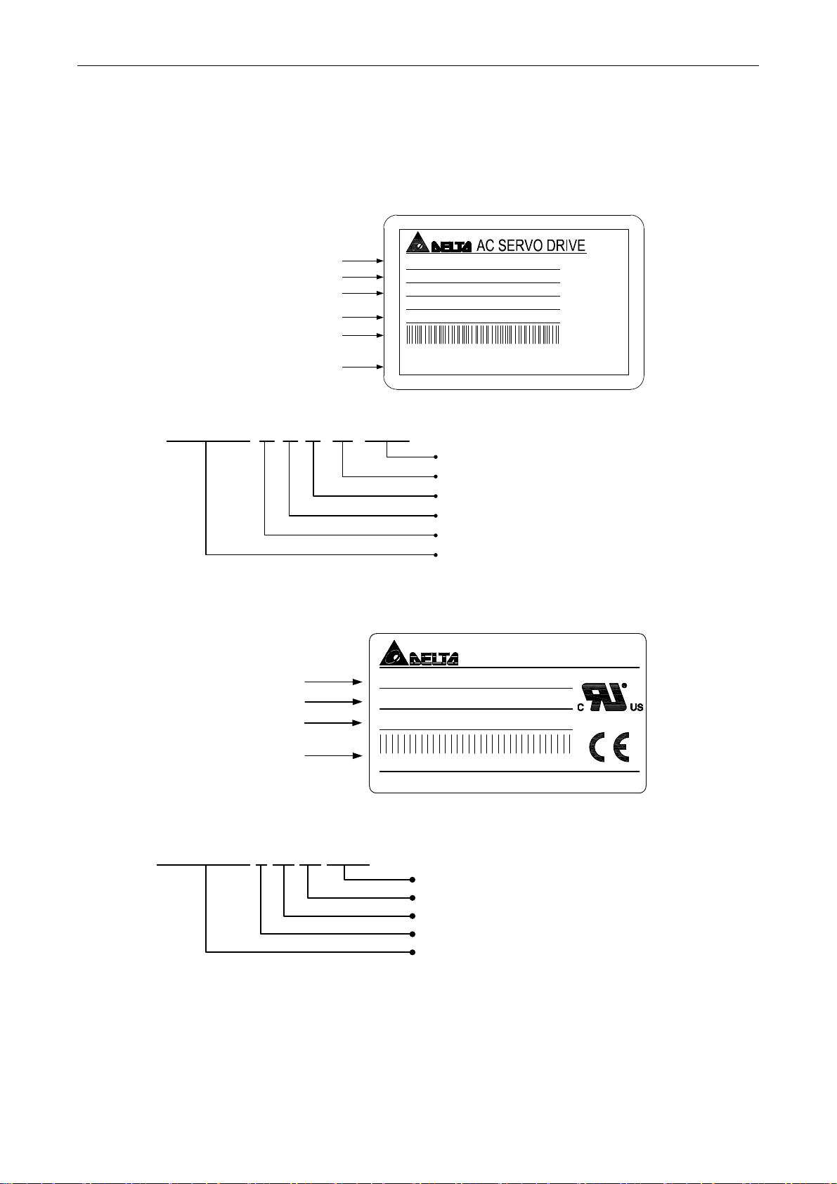
1.2.1 Nameplate Information ASDA-M Series Servo Drive
Nameplate Information
Model Name
Power Specification
Power Input Specification
Power Output Specification
Barcode & Serial Number
Firmware Version
Serial Number
M0721F 6 T 14 45 0003
ECMA Series Servo Motor
Nameplate Information
Model Name
Power Input Specification
Power Output Specification
Barcode &
Serial Number
Serial Number
MODEL : AS D - M-0721- F
POWER : 750W
INPUT : 200 ~ 230V 3PH 50/60H z 9. 51A
200~230V 1PH 50/60Hz 18.3A
OUTPUT : 110V 0-250Hz 5.1A
M0721M6T1100001
01.70
DELT A ELECTRO NICS, INC.
Serial Number
Production Week
Production Year
0: Year of 2010)
(starts from 0001 every week)
(from 1 to 52)
(14: Year of 2014 or
Production Factory
Delta St a ndard (
6: for RoHs)
Model Name
AC SERVO MOTOR
MODE L : ECMA- E 11320 RS
INPUT : kW 2.0 VAC 110 A 11.0
OUTPUT : r/min 2000 N.m 9.55 Ins.A
E11320RS T133 70017
Delta Electronics, Inc.
MADE IN TAIWAN
MADE IN XXXXXX
(T: Taoyuan; W: Wujiang)
E11320RS T 13 37 0017
Serial Num ber (S tarts from 00 01 every week)
Production Week (From 1 to 52)
Production Year (13: Year of 2013)
Production Factory (T: Taoyuan; W: Wujiang)
Model Name
1-2 Revision December, 2014
Page 16
ASDA-M Chapter 1 Inspection and Model Explanation
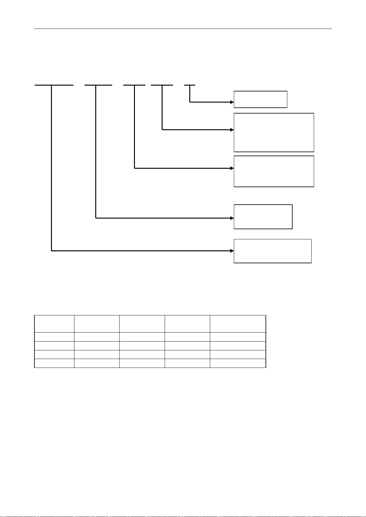
1.2.2 Model Explanation
ASDA-M Series Servo Drive
ASD-M-0721-L
Model T ype
Input Voltage and
Phase
21: 220V 1 phase/3
phase
Rated Power Input
07: 750W
15: 1.5kW
Model T ype
Type
M
F
L
R
Product Series
M
Product Name
AC SERVO Drive
Full-closed
Loop
○ ○ × ○
○ × ○ ○
○ × × ×
○ × ○ ○
CANopen DMCNET E-CAM
Revision December, 2014 1-3
Page 17
Chapter 1 Inspection and Model Explanation ASDA-M
A:A
ECMA Series Servo Motor
ECMA-C10602ES
Standard Shaft Diameter: S
Specific Shaft Diameter: 3=42mm,
7=14mm
Type of Shaft
Diameter and
Oil Seal
Round Shaft
(with fixed
screw holes)
Keyway E F G H
Keyway
(with fixed
screw holes)
w/o
Brake
w/o Oil
Seal
A B C D
P Q R S
with
Brake
w/o Oil
Seal
Rated Power Output
0F:50 W 05:500 W 10:1.0 kW
01:100 W 06:600 W 13:1.3 kW
02:200 W 07:750 W 15:1.5 kW
03:300 W 08:850 W 18:1.8 kW
04:400 W 09:900 W
w/o
Brake
with Oil
Seal
Motor Frame Size
04: 40 mm 09: 86 mm
06: 60 mm 10:100 mm
With
Brake
With Oil
Seal
08: 80 mm 13:130 mm
Name of the Series
Rated Voltage and Rated Speed
C = 220V/3,000 rpm; E = 220V/2,000 rpm;
F = 220V/1,500 rpm; G = 220V/1,000 rpm;
Sensor Type
1: Incremental, 20-bit (For the drive which
is under 3kW)
2: Incremental, 17-bit
3: 2500 ppr
A: Absolute ( Resolution of single cycle:
17-bit; Resolution/multi-cycle:16-bit)
Servo T ype
C Servo
Product Name
ECM: Electronic
Commutation Motor
1-4 Revision December, 2014
Page 18
ASDA-M Chapter 1 Inspection and Model Explanation
1.3 Servo Drive and Corresponding Servo Motor
ASDA-M Series Servo Drive
Servo Drive Corresponding Servo Motor
ECMA-C1040FS(S=8 mm)
750W ASD-M-0721-
1500W ASD-M-1521-
ECMA-C
ECMA-C
ECMA-C
ECMA-C△0604H ( H = high-inertia)
ECMA-C
ECMA-C
ECMA-C△0807H ( H=high-inertia)
ECMA-C
ECMA-E
ECMA-G
ECMA-G
ECMA-C△0807S(S=19 mm)
ECMA-C△0807H ( H=high-inertia)
ECMA-C
ECMA-C
ECMA-C
ECMA-E
ECMA-F△1308S(S=22 mm)
△0401S(S=8 mm)
△0602S(S=14 mm)
△0604S(S=14 mm)
△08047(7=14 mm)
△0807S(S=19 mm)
△0907S(S=16 mm)
△1305S(S=22 mm)
△1303S(S=22 mm)
△1306S(S=22 mm)
△0907S(S=16 mm)
△0910S(S=16 mm)
△1010S(S=22 mm)
△1310S(S=22 mm)
ECMA-F△1313S(S=22 mm)
ECMA-E△1315S(S=22 mm)
ECMA-G
△1309S(S=22 mm)
NOTE
1) Box, () at the end of the model name of the servo drive represents the code of
ASDA-M. Please refer to the type of purchasing product information.
2) Triangle, (△) in the mode name of the servo motor represents the type of encoder.
△=1: incremental, 20-bit;△=2: incremental, 17-bit; △=3: 2500 ppr; △=A: Absolute.
The listed model name is for reference. To purchase the product, please contact the
local dealer for product availability.
3) Box, () in the model name of the servo motor represents the type of brake or
keyway / oil seal.
The above table shows the specification of servo drive which has triple rated current. If the
user needs the servo drive which has six times of the rated current, please contact with
distributors. For detailed specification of the servo motor and servo drive, please refer to
the appendix.
Revision December, 2014 1-5
Page 19
Chapter 1 Inspection and Model Explanation ASDA-M
1.4 Features of Servo Drive
ASDA-M Series Servo Drive
1-6 Revision December, 2014
Page 20

ASDA-M Chapter 1 Inspection and Model Explanation
ASDA-M Series Servo Drive (top view)
Revision December, 2014 1-7
Page 21

Chapter 1 Inspection and Model Explanation ASDA-M
ASDA-M Series Servo Drive (bottom view)
1-8 Revision December, 2014
Page 22

Chapter 2 Installation
2.1 Notes
Please pay special attention to the followings:
1) Do not strain the cable connection between the servo drive and the servo motor.
2) Make sure each screw is tightened when fixing the servo drive.
3) The motor shaft and the ball screw should be parallel.
4) If the connection between the servo drive and the servo motor is over 20 meters, please
thicken the connecting wire, UVW as well as the encoder cable.
5) Tighten the fixed four screws of the motor.
2.2 Ambient Conditions of Storage
Before the installation, this product has to be kept in shipping carton. In order to retain the
warranty coverage and for the maintenance, please follow the instructions below when
storage, if the product is not in use temporally:
Store the product in a dry and dust-free location.
Store the product within an ambient temperature range of -20℃ to +65℃.
Store the product within a relative humidity range of 0% to 90% and a non-condensing
environment.
Avoid storing the product in the environment of corrosive gas and liquid.
It is better to store the product in shipping carton and put it on the shelf or working
platform.
Revision December, 2014 2-1
Page 23

Chapter 2 Installation ASDA-M
2.3 Ambient Conditions of Installation
The best temperature of this servo drive is between 0℃ and 55℃. If the temperature is over
45℃, please place the product in a well-ventilated environment so as to ensure its reliability
performance. If the product is installed in an electric box, make sure the size of the electric
box and its ventilation condition will not overheat and endanger the internal electronic
device. Also, pay attention to the vibration of the machine. Check if the vibration will
influence the electronic device of the electric box. Besides, the ambient conditions should
also include:
Location has no over-heat device.
Location has no water drop, vapor, dust and oily dust.
Location has no corrosive and inflammable gas and liquid.
Location has no airborne dust and metal particles.
Location has solid foundation and no vibration.
Location has no interference of electromagnetic noise.
The ambient temperature of the motor is between 0℃ and 40℃ and the ambient conditions
include:
Location has no over-heat device.
Location has not water drop, vapor, dust and oily dust.
Location has no corrosive and inflammable gas and liquid.
Location has no airborne dust and metal particles.
2-2 Revision December, 2014
Page 24
ASDA-M Chapter 2 Installation
2.4 Installation Direction and Space
Notes:
Follow the instructions for installation direction. Otherwise it is possible to cause
malfunction. In order to have well-cooling and circulation effect, the enough space between
adjacent objects and the baffle is needed. Or it might result in malfunction. When installing
AC servo drive, do not seal the suction hole and the vent hole. Do not place the drive in a
horizontal direction, or it might cause malfunction.
Revision December, 2014 2-3
Page 25
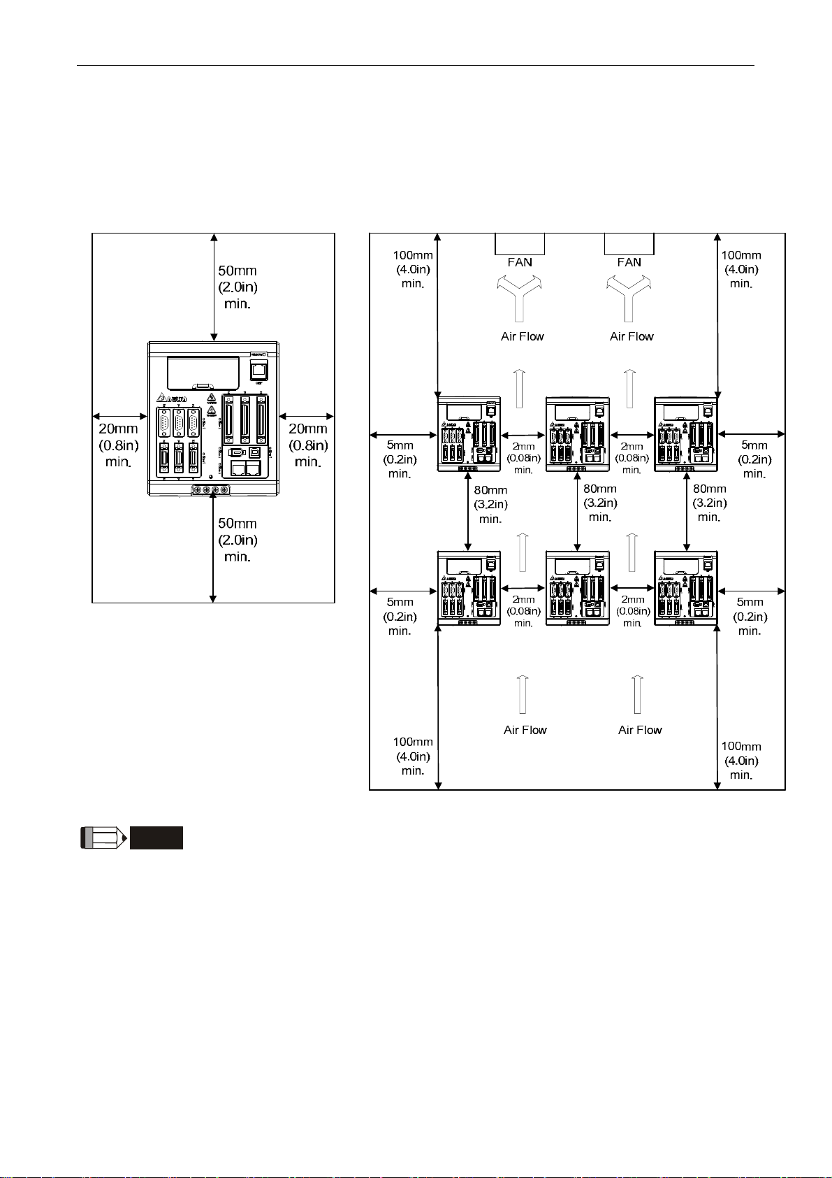
Chapter 2 Installation ASDA-M
Dimensions:
In order to have smaller wind resistance of the fan and increase the ventilation, please
follow the suggested clearance value when installing one or more than one servo drives.
(Refer to the following diagrams)
NOTE
2-4 Revision December, 2014
The above diagrams are not in equal proportion. Please refer to the
annotation.
Page 26
ASDA-M Chapter 2 Installation
2.5 Specification of Circuit Breaker and Fuse
Caution: Please use the fuse and circuit breaker that is recognized by UL/CSA.
Servo Drive Model Circuit breaker Fuse (Class T)
Operation Mode General General
ASD-M-0721-
ASD-M-1521-
30A 50A
70A 140A
If the servo drive equips with earth leakage circuit breaker for avoiding
NOTE
electric leakage, please choose the current sensitivity which is over
200mA and can continue up to 0.1 seconds.
2.6 EMI Filters Selection
Item Power Servo Drive Model EMI Filter Model FootPrint
1 750W ASD-M-0721- 20TDT1W4D N
2 1500W ASD-M-1521- 20TDT1W4D N
EMI Filter Installation
All electronic equipment (including servo drive) generates high or low frequency noise
during operation and interfere the peripheral equipments via conduction or radiation. With
EMI Filter and the correct installation, much interference can be eliminated.
When installing servo drive and EMI Filter, please follow the instructions of the user manual
and make sure it meets the following specification.
1. EN61000-6-4 (2001)
2. EN61800-3 (2004) PDS of category C2
3. EN55011+A2 (2007) Class A Group 1
Revision December, 2014 2-5
Page 27

Chapter 2 Installation ASDA-M
General Precaution
In order to ensure the best performance of EMI Filter, apart from the instructions of servo
drive installation and wiring, please follow the precautions mention below:
1. The servo drive and EMI Filter should be installed on the same metal plate.
2. When installing servo drive and EMI Filter, the servo drive should be installed above
the EMI Filter.
3. The wiring should be as short as possible.
4. The metal plate should be well grounded.
5. The metal cover of the servo drive and EMI Filter or grounding should be firmly fixed
on the metal plate. Also, the contact area should be as large as possible.
Motor Cable Selection and Installation Precautions
The selection of motor cables and correct installation affect the performance of EMI Filter.
Please follow the precautions mention below.
1. Use the cable that has braid shielding (The effect of double shielding is better)
2. The shield on both sides of the motor cable should be grounded in the shortest
distance and the largest contact area.
3. The protective paint of the U-shape saddle and metal plate should be removed in
order to ensure the good contact. Please see disgram 1.
4. It should have correct connection between the braid shielding of the motor cable and
the metal plate. The braid shielding on both sides of the motor cable should be fixed
by the U-shape saddle and metal plate. Please see diagram 2 for the correct
connection.
2-6 Revision December, 2014
Page 28
ASDA-M Chapter 2 Installation
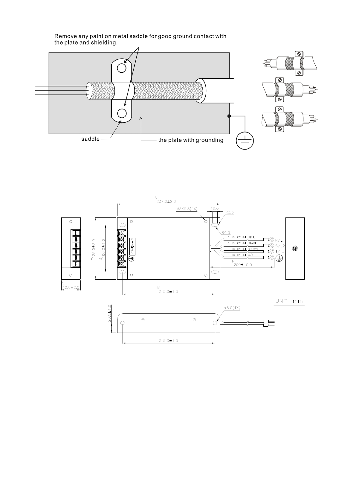
Diagram 1 Diagram 2
Dimensions of EMI Filter
Delta Part Number: 20TDT1W4D
Revision December, 2014
2-7
Page 29

Chapter 2 Installation ASDA-M
2.7 Selection of Regenerative Resistor
When the direction of pull-out torque is different from the rotation, it means the electricity is
sent back to the servo drive from the load-end. It becomes the capacitance of DC Bus and
increases the voltage. When the voltage increases to a specific value, the come-back
eletricity can only be consumed by regenerative resistor. There is a built-in regenerative
resistor in the servo drive. Users can also use the external regenerative resistor if needed.
The following table is the specification of built-in regenerative resistor provided by ASDA-M
series.
Specification of built-in
Servo Drive
(kW)
0.75 40 60 30 30
1.5 20 100 50 20
*1 The capacity of built-in regenerative resistor (average value) is 50% of the rated capacity
of the built-in regenerative resistor. The capacity of the external regenerative resistor is
the same as the built-in one.
When the regenerative resistor exceeds the capacity of built-in regenerative resistor, the
external regenerative resistor should be applied. Please pay special attention to the
followings when using the regenerative resistor.
1. Please correctly set up the resistance (P1-52) and capacity (P1-53) of the
regenerative resistor. Or it might influence the performance of this function.
regenerative resistor
Resistance
(P1-52) (Ohm)
Capacity
(P1-53) (Watt)
*1 The capacity of
built-in regenerative
resistor
(Watt)
Minimum allowable
resistance
(Ohm)
2. If users desire to use the external regenerative resistor, please make sure the applied
value is the same as the built-in regenerative resistor. If users desire to connect it in
parallel to increase the power of regenerative resistor, please make sure the
capacitance meets the requirements.
3. In natural environment, if the capacity of regenerative resistor (the average value) is
within the rated capacity, the temperature of the capacitance will increase to 120℃ or
even higher (under the condition of regenerative energy keeps existing). For safety
concerns, please apply the method of forced cooling in order to reduce the
temperature of regenerative resistor. Or, it is suggested to use the regenerative
resistor which is equipped with thermal switches. Please contact the distributors for
load characteristics of the regenerative resistor.
2-8 Revision December, 2014
Page 30
ASDA-M Chapter 2 Installation
When using the external regenerative resistor, the resistor should connect to P, C terminal
and the contact of P, D terminal should be opened. It is recommended to choose the above
mentioned capacitance. For easy calculation of regenerative resistor capacity, except the
energy consumed by IGBT, two ways are provided to select the capacity of external
regenerative resistor.
(1) Regenerative Power Selection
(a) When the external load on torque does not exist
If the motor operates back and forth, the energy generated by the brake will go into
the capacitance of DC bus. When the voltage of the capacitance exceeds a specific
value, the redundant energy will be consumed by regenerative resistor. Two ways of
selecting regenerative resistor are provided here. The table below provides the
energy calculation method. Users can refer to it and calculate the selected
regenerative resistor.
Servo Drive
(kW)
0.75
0.75
0.75
0.75
Low
Inertia
0.75
0.75
0.75
1.5
1.5
0.75
Medium
Inertia
1.0
2.0
Motor
ECMA-Cᇞ040F□□
ECMA-Cᇞ0401□□
ECMA-Cᇞ0602□□
ECMA-Cᇞ0604□□
ECMA-Cᇞ0804□□
ECMA-Cᇞ0807□□
ECMA-Cᇞ0907□□
ECMA-Cᇞ1010□□
ECMC-Cᇞ0910□□
ECMA-Eᇞ1305□□
ECMA-Eᇞ1310□□
ECMA-Eᇞ1315□□
Regenerative
Rotor Inertia
J
-4
(× 10
kg.m2)
0.021
0.037
0.177
0.277
0.68
1.13
1.93
2.65
2.62
power from
empty load
3000r/min to
stop
Eo (joule)
0.10 4.21
0.18 4.21
0.87 5.62
1.37 8.42
3.36 8.42
5.59 17.47
9.54 17.47
13.10 21.22
12.96 21.22
8.17 40.40
8.41 41.59
The Maximum
regenerative
power of
capacitance
Ec (joule)
8.42
21.22
11.18 55.29 25.58
Medium-High
Inertia
High
Inertia
Eo= J * wr2/182(joule), Wr : r/min
Revision December, 2014 2-9
1.5
0.75
0.75
1.5
ECMA-Fᇞ1308□□
ECMA-Gᇞ1303□□
ECMA-Gᇞ1306□□
ECMA-Gᇞ1309□□
13.6 67.25 21.22
8.17 17.96 8.42
8.41 18.48 17.47
11.18 24.57 21.22
Page 31

Chapter 2 Installation ASDA-M
Assume the load inertia is N times to the motor inertia and the motor decelerates from
3000r/min to 0, its regenerative energy is (N+1) × Eo. The consumed regenerative
resistor is (N+1) × Eo-Ec joule. If the cycle of back and forth operation is T sec, then
the power of regenerative resistor it needs is 2×((N+1) × Eo-Ec)/ T.
Followings are the calculation procedure:
Steps Item Calculation and Setting Method
Set the capacity of regenerative
1
Set P1-53 to the maximum value
resistor to the maximum
Set T cycle of back and forth
2
Enter by the user
operation
3 Set the rotational speed wr Enter by the user or read via P0-02
4 Set the load/motor inertia ratio N Enter by the user or read via P0-02
Calculate the maximum
5
Eo= J * wr2/182
regenerative energy Eo
Set the absorbable regenerative
6
Refer to the above table
energy Ec
Calculate the needful capacitance
7
2 ×((N+1) × Eo-Ec)/ T
of regenerative resistor
Take 400W as the example, the cycle of back and forth operation is T = 0.4sec, the
maximum speed is 3000r/min and the load inertia is 7 times to the motor inertia. Then,
the needful power of regenerative resistor is 2 ×((7+1) × 1.68-8)/ 0.4 = 27.2W. If it is
smaller than the built-in capacity of regenerative resistor, the built-in 60W
regenerative resistor will do. Generally speaking, when the need of the external load
inertia is not much, the built-in regenerative is enough. The diagram below describes
the actual operation. The smaller power of the regenerative resistor it has, the more
energy it accumulates and the higher temperature will be. When the temperature is
higher than a specific value, ALE05 occurs.
2-10 Revision December, 2014
Page 32

ASDA-M Chapter 2 Installation
(b) When the external load torque exists, the motor is in reverse rotation.
Usually, the motor is in forward rotation, which means the torque output direction of
the motor is the same as the rotation direction. However, in some applications, the
direction of torque output is different from the rotation. In this situation, the motor is in
reverse rotation. The external energy goes into the servo drive through the motor. The
diagram below is one of the examples. When the motor is in constant speed, it is
positive torque in most of the time and a huge amount of energy rapidly transmits to
regenerative resistor.
Negative torque: TL × Wr TL: external load torque
For safety reasons, please calculate it by considering the safest situation.
For example, when the external load torque is the +70% rated torque and the rotation
reaches 3000 r/min, then take 400W (the rated torque is 1.27Nt-m) as the example,
the user has to connect the regenerative resistor which is 2 × (0.7× 1.27) × (3000 × 2 × π
/60) = 560W.
(2) Simple Selection
Choose the appropriate regenerative resistor according to the allowable frequency
and empty load frequency in actual operation. The so-called empty allowable
frequency is the frequency of continuous operation when the servo motor runs from
Revision December, 2014
2-11
Page 33

Chapter 2 Installation ASDA-M
0r/min to the rated speed and then decelerates from the rated speed to 0r/min. The
following table lists the allowable frequency of built-in regenerative resistor when the
servo drive runs without load (times/min).
Allowable frequency of built-in regenerative resistor when the servo drive runs without load
(times/min)
Motor Capacity
Corresponding
Motor
ECMA□□C
ECMA□□E
ECMA□□G
When the servo motor runs with load, the allowable frequency will be different
according to different load inertia or speed. The following is the calculation method.
m represents load / motor inertia ratio.
Allowable frequency =
The comparison table of external regenerative resistor is provided below. Please
600W 750W 900W 1.0kW 1.5kW
06 07 09 10 15
- 312 - 137 -
- - - 42 32
42 - 31 - -
2
Allowable frequency when servo motor run without load
m + 1
Rated speed
x
Operating speed
times
min.
choose the appropriate regenerative resistor according to the allowable frequency.
The table below describes the suggested allowable frequency (times/min) of
regenerative resistor when the servo drive runs without load.
2-12 Revision December, 2014
Page 34

ASDA-M Chapter 2 Installation
Allowable frequency of regenerative resistor when the servo drive runs without load
(times/min)
Motor Capacity
Suggested Regenerative
400W
200W
(F60)
ECMA□□C
400W
750W 1.0kW
(F80)
02 04 04 07 10
Resistor
BR400W040 (400W 40Ω) - 8608 3506 2110 925
BR1K0W020 (1kW 20Ω) - - 8765 5274 2312
Motor Capacity
0.5kW 1kW 1.5kW
ECMA□□E
Suggested Regenerative
Resistor
05 1.0 15
BR400W040 (400W 40Ω) 291 283 213
BR1K0W020 (1kW 20Ω) 729 708 533
Motor Capacity
0.3kW 0.6kW 0.9kW
ECMA□□G
Suggested Regenerative
Resistor
03 06 09
BR400W040 (400W 40Ω) 292 283 213
BR1K0W020 (1kW 20Ω) 729 708 533
If watt is not enough when using regenerative resistor, connecting the same regenerative
resistor in parallel can increase the power.
ASDA-M can control three motors at the same time. If the energy of three
NOTE
motors goes into the servo drive, the power of regenerative resistor
needs to be increased to three times of the origin.
Revision December, 2014 2-13
Page 35

Chapter 2 Installation ASDA-M
Dimensions of Regenerative Resistor
Delta Part Number: BR400W040 (400W 40Ω)
L1 L2 H D W MAX. WEIGHT (g)
265 250 30 5.3 60 930
Delta Part Number: BR1K0W020 (1kW 20Ω)
L1 L2 H D W MAX. WEIGHT (g)
400 385 50 5.3 100 2800
2-14 Revision December, 2014
Page 36

ASDA-M Chapter 2 Installation
Delta Part Number: BR1K5W005 (3kW 10Ω)
Revision December, 2014 2-15
Page 37

Chapter 2 Installation ASDA-M
(This page is intentionally left blank.)
2-16 Revision December, 2014
Page 38

Chapter 3 Wiring
This chapter details the wiring method of servo drive, the definition of each signal and
standard wiring diagram.
3.1 Connection between Peripheral Devices and Main Power
Circuit
3.1.1 Wiring Diagram of Peripheral Devices
Revision December, 2014 3-1
Page 39

Chapter 3 Wiring ASDA-M
NOTE
Installation Notes:
1) Check if the power and wiring among R, S, T and L1c, L2c are correct.
2) Check if the output terminal U, V, W of the servo motor is correctly wired. The
incorrect wiring may disable the operation of the motor or cause the malfunction.
3) When applying to the external regenerative resistor, the contact between P
D should be opened and the external regenerative resistor should connect to
terminal P
contact between P
should be opened.
4) When an alarm occurs or the system is in emergency stop status, use ALARM or
WARN to output and disconnect the power of magnetic contactor in order to
disconnect the power of servo drive.
and C. When applying to the internal regenerative resistor, the
and D should be closed and the contact between P and C
and
3-2 Revision December, 2014
Page 40

ASDA-M Chapter 3 Wiring
3.1.2 Connectors and Terminals of the Servo Drive
Terminal
Name Description
Signal
L1c, L2c Power input of the
control circuit
R, S, T Power input of the main
circuit
U, V, W
FG
P , D,
C,
CN1 I/O connector (option) Connect to the host controller, please refer to Section 3.3
Motor cable Connect to the motor
Regenerative resistor
terminal or brake unit
Ground terminal
Connect to single-phase AC power (select the
appropriate voltage specification according to the
product )
Connect to three-phase AC power (select the appropriate
voltage specification according to the product)
Terminal
Symbol
U Red
V White
W Black
FG Green
Use internal resistor The contact between P
Use external
resister
Use external
braking unit
Connect to the ground wire of the power and the servo
motor
Wire
Color
Description
Three-phase main power cable of
the motor
Connect to the grounding
the servo drive.
end should be closed; contact
between P
opened.
Connect P , C ends to the resistor
and the contact between P
D end should be opened.
P and P of the brake unit
should connect to P
respectively. The contact between
P
and D and P and C should
be opened.
and C end should be
and P
of
and D
and
CN2 Connector (option) Connect to the encoder of the motor, please refer to
Section 3.4
CN3 Connector (option) Connect to RS-485 or RS-232, please refer to Section
3.5
CN4 USB connector
(Type B) (option)
CN5 Connector (option) Connect to the linear scale or encoder to constitute a
CN6 CANopen connector
(option)
Connect to personal computer (PC or NOTEBOOK),
please refer to Section 3.6
full-closed loop, please refer to Section 3.7
RJ45 connector, please refer to Section 3.8
Pay special attention to the followings when wiring:
1) When the power is cutoff, do not touch R, S, T and U, V, W since the capacitance
inside the servo drive still contains huge amount of electric charge. Wait until the
charging light is off.
2) Separate R, S, T and U, V, W from the other wires. The interval should be at least 30
cm (11.8 inches).
Revision December, 2014 3-3
Page 41

Chapter 3 Wiring ASDA-M
3) If the wire of encoder CN2 or CN5 connecter is not long enough, please use shielded
twisted-pair cable which cannot exceed 20 meters (65.62 inches). If it exceeds 20
meters, please choose the bigger wire diameter of signal cable to ensure it will not
cause signal fading. As for the encoder wiring specification of 20-meter-long cable,
please use AWG26 of wire size and Metal braided shield twisted-pair cable which
complies with the standard of UL 2464.
4) When using CANopen, please use the standard shielded twisted-pair cables to
ensure the communication quality.
5) When selecting the wire rod, please refer to Section 3.1.6.
3-4 Revision December, 2014
Page 42

ASDA-M Chapter 3 Wiring
3.1.3 Wiring Method
The wiring method of ASDA-M servo drive is divided into single-phase and three-phase.
In the diagram below, Power On is contact a, Power Off and ALRM_RY are contact b.
MC is the coil of magnetic contactor and self-remaining power and is the contact of main
power circuit.
Wiring Method of Single-phase Power Supply ( suitable for all series)
RS
MCCB
Noise Filter
Power
On
Power
Off
MC
ALRM_RY
DC24V
MC
ALRM_RY
MC
R
S
T
L1C
L2C
DO3+_X
DO3-_X
SUP
Servo Drive
U_X
V_X
W_X
U_Y
V_Y
W_Y
U_Z
V_Z
Motor_X
Motor_Y
Motor_Z
W_Z
DC24V
ALRM_RY
DC24V
ALRM_RY
Revision December, 2014 3-5
DO3+_Y
DO3-_Y
DO3+_Z
DO3-_Z
Page 43

Chapter 3 Wiring ASDA-M
Wiring Method of Three-phase Power Supply ( suitable for all series)
3-6 Revision December, 2014
Page 44

ASDA-M Chapter 3 Wiring
3.1.4 Specification of Motor U, V, W Power Cable
Motor Model
ECMA-C1040FS (50W)
ECMA-C△0401S (100W)
ECMA-C△0602S (200W)
ECMA-C△0604S (400W)
ECMA-C△0604H (400W)
ECMA-C△08047 (400W)
ECMA-C△0807S (750W)
ECMA-C△0807H (750W)
ECMA-C△0907S (750W)
ECMA-C△0910S (1000W)
ECMA-C1040FS (50W)
ECMA-C△0401S (100W)
ECMA-C△0602S (200W)
ECMA-C△0604S (400W)
ECMA-C△0604H (400W)
ECMA-C△08047 (400W)
ECMA-C△0807S (750W)
ECMA-C△0807H (750W)
ECMA-C△0907S (750W)
ECMA-C△0910S (1000W)
U、V、W/Connector of Mechanical Brake
HOUSING: JOWLE (C4201H00-2*2PA)
HOUSING:JOWLE (C4201H00-2*3PA)
Terminal
Definition
A
B
*:with brake
ECMA-G△1303S (300W)
ECMA-E△1305S (500W)
ECMA-G△1306S (600W)
ECMA-F△1308S (850W)
ECMA-G△1309S (900W)
ECMA-C△1010S (1000W)
ECMA-E△1310S (1000W)
ECMA-E△1315S (1500W)
C
Revision December, 2014 3-7
Page 45

Chapter 3 Wiring ASDA-M
Wiring Name
Terminal
Definition A
Terminal
Definition B
Terminal
Definition C
Terminal
Definition D
U
(Red) V (White)W (Black)
1 2 3 4 - -
1 2 4 5 3 6
F I B E G H
D E F G A B
CASE GROUND
(Green)
BRAKE1
(Yellow)
BRAKE2
(Blue)
When selecting the wire rod, please choose 600V PVC cable and the length should not
longer than 30m. If the length exceeds 30m, please take the received voltage into
consideration when selecting the wire size. Please refer to Section 3.1.6 for wire rod
selection.
NOTE
1) Box, () in servo motor model represents brake or keyway / oil seal.
2) Triangle, (△) in servo motor model represents encoder type. △=1: incremental,
20-bit; △=2: incremental, 17-bit; △=3: 2500 ppr; △=A: absolute.
3-8 Revision December, 2014
Page 46

ASDA-M Chapter 3 Wiring
3.1.5 Specification of Connector of Encoder Cable
Encoder connection diagram 1:
NOTE
This diagram shows the connection between the servo drive and the motor encoder. It
is not drew by the practical scale and specification will be dif f erent according to the
selected servo drive and motor model.
1) Please refer to the Section of Specification and Definition of Encoder Connector.
2) Please refer to Section 3.4 CN2 Connector.
Motor Model Connector of Encoder Cable
ECMA-C1040FS (50W)
ECMA-C△0401S (100W)
ECMA-C△0602S (200W)
ECMA-C△0604S (400W)
ECMA-C△0604H (400W)
ECMA-C△08047 (400W)
ECMA-C△0807S (750W)
ECMA-C△0807H (750W)
ECMA-C△0907S (750W)
ECMA-C△0910S (1000W)
Revision December, 2014 3-9
Page 47

Chapter 3 Wiring ASDA-M
Specification and Definition of Encoder Connector:
Connecto r of
Encoder Cable
Housing : AMP( 1-172161-9)
Connecto r of
Motor Encoder
Servo Drive
CN2
Servo Drive
CN2
View from this side
123
Blue
Reserved
T+
Reserved
456
Blue/Black
Reserved Reserved
T-
789
Red/Red &
white
Black/Black
& white
Shield
DC+5V GND
The wire color of the servo drive
is for reference only. Plea se refer
to the real objec t.
1
2
33
44
‧
‧
‧
2
‧
‧
‧
View from
this sid e
(Encoder type is 17bit , 20bit):
23
Reserved
6
Reserved
-
5
-
9
Shield
Blue Brown
(Encoder type is 2500ppr, 33bit):
23
Reserved Reserved
6
Reserved Reserved
5
9
Shield
1
Blue
Motor
Encoder
1
White
T+
4
White/Red
T-
78
DC+5VGND
1
White
T+
4
White/Red
T-
78
Brown
DC+5VGND
Motor
Encoder
If not using housing and directly wire the cores, please follow the corresponding core number for wiring. For
example, core number 1 from the servo drive CN2 should connect to core number 1 from the motor encoder;
core number 2 from the servo drive CN2 should connect to core number 2 from the motor encoder and so on.
Please number the cores from the servo drive in order and then connect it to the encoder.
3-10 Revision December, 2014
Page 48

ASDA-M Chapter 3 Wiring
Encoder connection diagram 2:
NOTE
This diagram shows the connection between the servo drive and the motor encoder. It
is not drew by the practical scale and specification will be different according to the
selected servo drive and motor model.
1) Please refer to Section 3.4, CN2 Connector.
Motor Model Connector of Encoder Cable
ECMA-G△1303S (300W)
ECMA-E△1305S (500W)
ECMA-G△1306S (600W)
ECMA-F△1308S (850W)
ECMA-G△1309S (900W)
ECMA-C△1010S (1000W)
ECMA-E△1310S (1000W)
ECMA-F△1313S (1300W)
ECMA-E△1315S (1500W)
Pin
No.
Terminal
Symbol
Wire
Color
T+ Blue
B T -
Blue &
Black
Red /
S DC+5V
Red &
White
Black /
R GND
Black &
White
BRAID
L
SHIELD
–
Revision December, 2014 3-11
Page 49

Chapter 3 Wiring ASDA-M
A
A
Please select shielded multi-core and the shielded cable should connect to the SHIELD
end. Please refer to the description of Section 3.1.6.
NOTE
1) Box, () in servo motor model represents brake or keyway / oil seal.
2) Triangle, (△) in servo motor model represents encoder type. △=1: incremental,
20-bit; △=2: incremental, 17-bit; △=3: 2500 ppr; △=A: absolute.
3.1.6 Selection of Wire Rod
The recommended wire rods are shown as the following table.
Servo Drive and corresponding
Motor Model
ASD-M-0721-
ASD-M-1521-
ECM
ECMA-C△0401S
ECMA-C△0602S
ECMA-C△0604S
ECMA-C△0604H
ECMA-C△08047
ECMA-C△0807S
ECMA-C△0807H
ECMA-C△0907S
ECMA-E△1305S
ECMA-G△1303S
ECMA-G△1306S
ECM
ECMA-C△1010S
ECMA-E△1310S
ECMA-E△1315S
ECMA-F△1308S
ECMA-G△1309S
ECMA-C△0807S
ECMA-C△0907S
-C1040FS
-C△0910S
Servo Drive
Model
ASD-M-0721-
ASD-M-1521-
Size Number Specification Standard Length
0.13(AWG26)
0.13(AWG26)
1.3(AWG16)2.1(AWG14)0.82(AWG18) 2.1(AWG14)
1.3(AWG16)3.3(AWG12)1.3(AWG16) 3.3(AWG12)
Encoder Wiring —Wire Diameter mm² (AWG)
Power Wiring-Wire Diameter mm² (AWG)
L1c, L2c R, S, T U, V, W P , C
10 cores
(4 pairs)
10 cores
(4 pairs)
UL2464 3 mm (9.84 inches)
UL2464 3 mm (9.84 inches)
NOTE
3-12 Revision December, 2014
1) Please use shielded twisted-pair cable for encoder wiring so as to reduce the
interference of the noise.
2) The shield should connect to the
3) Please follow the Selection of Wire Rod when wiring in order to avoid the danger it
may occur.
4) Box, () at the end of the servo drive model represents the model code of
ASDA-M. Please refer to the model information of the product you purchased.
5) Triangle, () in servo motor model represents brake or keyway / oil seal.
phase of SHIELD.
Page 50

ASDA-M Chapter 3 Wiring
6) Box, (△) in servo motor model represents encoder type. △=1: incremental,
20-bit; △=2: incremental, 17-bit; △=3: 2500 ppr; △=A: absolute.
Revision December, 2014 3-13
Page 51

Chapter 3 Wiring ASDA-M
3.2 Schematic Diagram of Servo System
750W~1.5kW Model (Built-in Regenerative Resistor and Fan)
Power
750W、1.5k W single/three-phas e 200~230V
Lack phase
R
detection
S
T
L1c
L2c
A/D
Current signal
processing
Serial
Communication
RS-232/485
USB
CN3
CN4
CN6
Power
circuit
N
P
Rectifying
Control
A/D
External regenerative
resistor
±15V
18V
24V
5V
GATE
DRIVER
Protect
circuit
Current
Control
Speed Control
Position
Control
DSP
operation
DPC
Regeneration
Circuit
Data Bus
750W one group of fan
1.5 one gr oup of fa n
12V
IGBT_X
IGBT_Y
IGBT_Z
PWM Output
Encoder signal
processing
CPLD
processing
U_X
V_X
W_X
U_Y
V_Y
W_Y
U_Z
V_Z
W_Z
CN2_Z
CN2_Y
CN2_X
CN5_X
CN5_Y
CN5_Z
Motor
Servo Motor
Motor
Servo Motor
Motor
Servo Motor
Full-closed
loop
Full-closed
loop
Full-closed
loop
Encoder
Encoder
Encoder
Encoder
Encoder
Encoder
CN5_X
CN5_Y
CN5_Z
A/D
Operation
Display
SET
UP DOW N
SHIFT
MODE
CN1_X
Ext er na l speed
External torque
CN1_Y
Ext er na l speed
Po si ti on pu lse
Analog outp ut
Digital out put
Digital input
External torque
Po si ti on pu lse
A, B, Z Output
Analog outp ut
Digital out put
Digit al Input
CN1_Z
Ext er na l speed
External torque
Po si ti on pu lse
A, B, Z Output
Digital out put
A,B,Z Output
Analog outp ut
Digital input
SEL
NOTE
1) The extension socket CN6 of ASD-M-0721-M model and ASD-M-1521-M is the function of
CANopen.
2) The extension socket CN6 of ASD-M-0721-F model and ASD-M-1521-F is the function of
DMCNET.
3) ASD-M-0721-L model and ASD-M-1521-L model have no extension socket CN6.
3-14 Revision December, 2014
Page 52

ASDA-M Chapter 3 Wiring
3.3 I/O Signal (CN1) Connection
3.3.1 I/O Signal (CN1) Connector Terminal Layout
In order to have a more flexible communication with the master, 9 programmable Digital
Outputs (DO) and 18 programmable Digital Inputs (DI) are provided. The setting of 6 digital
inputs and 3 digital outputs of each axis provided by ASDA-M, which are parameter
P2-10~P2-15 and parameter P2-18~P2-20 respectively. In addition, the differential output
encoder signal, A+, A-, B+, B-, Z+ and Z-, input of analog torque command, analog
speed/position command and pulse position command are also provided. The followings
are the pin diagrams.
CN1 Connector (female) Side view
Rear view
26
/HPulse
NC /SIGN
27 49
NC DO3+ DO2+ DO1+ DI1-
1
NC
DI5-
PULLHI_S
COM+
HPulse
/HSIGN V_REF
PULLHI_P
MON2
/PULSE PULSE
VDD OB/OBGND
GND
GND OA
HSIGN
COM- COM-
OCZ
COM-
OZDI6- DI3-NCNCNC SIGN
50
25
2 24
DI4- DI2-DO1-DO2-DO3- GND NC
MON1 T_REF
VCC /OA /OZ
The rear wiring terminal of CN1 connector
Revision December, 2014 3-15
Page 53

Chapter 3 Wiring ASDA-M
2 DO3- Digital output
4 DO2- Digital output
6 DO1- Digital output
8 DI4- Digital input
10 DI2- Digital input
Analog input
12 GND
14 NC
16 MON1
18 T_REF
20 VCC
22 /OA
24 /OZ
signal
ground
No
connection
Analog
monitor
output 1
Torque
analog
command
input
+12 power
output (for
analog
command)
Encoder/
A pulse
output
Encoder/
Z pulse
output
1 NC Reserved
3 DO3+
5 DO2+
7 DO1+
9 DI1- Digital input 34 DI3- Digital input
11 COM+
13 GND
15 MON2
17 VDD
19 GND
21 OA
23 /OB
25 OB
Digital
output
Digital
output
Digital
output
Power input
(12~24V)
Analog input
signal
ground
Analog
monitor
output 2
+24V power
output (for
external I/O)
Analog input
signal
ground
Encoder/
A pulse
output
Encoder/
B pulse
output
Encoder/
B pulse
output
27 NC Reserved
High-speed
29 /HPULSE
31 NC Reserved
33 DI5- Digital input
PULL
35
HI_S
(Sign)
37 /SIGN
PULL
39
HI_P
(Pulse)
41 /PULSE
43 PULSE
45 COM-
47 COM-
49 COM-
position
command
pulse (-)
Pull-high
voltage of
sign
Position
command
signal ( - )
Pull-high
voltage of
pulse
Position
command
pulse ( - )
Position
command
pulse ( + )
VDD(24 V)
power
ground
VDD(24 V)
power
ground
VDD(24V)
power
ground
NOTE
1) NC means NO CONNECTION. This terminal is for internal use only.
Do not connect it, or it may damage the servo drive.
26 NC Reserved
28 NC Reserved
30 NC Reserved
32 DI6- Digital input
Position
36 SIGN
38 HPULSE
40 /HSIGN
42 V_REF
44 GND
46 HSIGN
48 OCZ
50 OZ
command
signal (+)
High-speed
position
command
pulse (+)
High-speed
position
command
(-)
Speed analog
command
input
(+)
Analog input
signal ground
High-speed
position
command
(+)
Encoder
Z pulse
open-collector
output
Encoder
Z pulse
differential
output
2) CN1 of the three axes all have MON1 and MON2 output; however, the
internal circuit is parallel-connected (please refer to Chapter 3.3 Basic
Wiring); the three axes share the same set of MON1 and MON2.Thus,
when the external circuit connects to any of the axis’ MON1 and
MON2, the final output will be the same. In addition, monitoring item of
analog output is determined by the setting of P0-03.
3-16 Revision December, 2014
Page 54

ASDA-M Chapter 3 Wiring
3.3.2 Explanation of I/O (CN1) Connector Signal
The following details the signals listed in previous section:
General Signals
Wiring
Signal Name Pin No Function
(1) The speed command of the motor is
-10V ~ +10V which means the speed
command is -3000 ~ +3000 r/min
(default). It can change the
Method
(Refer to
3.3.3)
Analog
Command
(input)
Analog
Monitor
(output)
V_REF 42
(2) The position command of the motor is
The torque command of the motor is -10V ~
T_REF 18
+10V which means the rated torque
command of -100% ~ +100%.
The operating state of the motor can be
shown by analog voltage, such as speed
and current. This drive provides two channel
outputs. Users can select the desired
monitoring data via parameter P0-03. This
MON1
MON2
16
15
signal is based on the power ground. The
internal circuit is parallel-connected (please
refer to Chapter 3.3 Basic Wiring); three
axes share the same set of MON1 and
corresponding range via parameters.
-10V ~ +10V which means the position
command is -3 cycles ~ +3 cycles
(default).
C1
C1
C2
MON2.Thus, when the external circuit
connects to any of the axis’ MON1 and
MON2, the final output will be the same.
Position pulse can be inputted by Line Driver
(single phase max. frequency 500KHz) or
open-collector (single phase max. frequency
200KHz). Three kinds of command type can
be selected via P1-00, CW pulse + CCW
pulse, pulse + direction, A pulse + B pulse.
When position pulse uses open-collector,
C3/C4
Position
Pulse
(input)
PULSE
/PULSE
SIGN
/SIGN
PULL HI_P
PULL HI_S
43
41
36
37
39
35
the terminal should be connected to an
external applied power in order to pull high.
Revision December, 2014 3-17
Page 55

Chapter 3 Wiring ASDA-M
Wiring
Signal Name Pin No Function
Method
(Refer to
3.3.3)
High-speed position pulse only accepts Line
Drive (+5V) as the input type.
High-spee
d position
pulse
(input)
HPULSE
/HPULSE
HSIGN
/HSIGN
38
29
46
40
The max. frequency of single phase is
4MHz. There are three kinds of command
types, A pulse + B pulse, CW pulse + CCW
C4-2
pulse and pulse + direction. Please refer to
parameter P1-00.
Position
pulse
(output)
OA
/OA
OB
/OB
OZ
/OZ
21
22
25
23
50
24
Encoder signal output A, B, Z (Line Drive
output)
C13/C14
Encoder signal output Z (Open-collector
OCZ 48
-
output)
Power
VDD is the +24V power provided by the
drive and is for Digital Input (DI) and Digital
VDD 17
Output (DO) signal. The maximum current is
500mA.
COM+ is the common input of Digital Input
(DI) and Digital Output (DO) voltage. When
COM+
COM-
11
45
47
49
using VDD, VDD should be connected to
COM+. If not using, it needs to apply the
external power (+12V ~ + 24V). Its positive
end should connect to COM+ and the
negative end should connect to COM-.
VCC is the +12V power provided by the
drive. It is used for providing the simple
VCC 20
analog command (speed or torque
command). The maximum current is 100mA.
GND
12,13,
19,44
VCC voltage is based on GND.
NO CONNECTION. This terminal is for
-
Other NC 14
internal use only. Do not connect it, or it may
damage the servo drive.
There are numerous operation mode of this servo drive (please refer to Chapter 6.1).
Each operation mode needs different I/O signal. In order to use the terminal in a more
efficient way, the selection of I/O signal has to be programmable. That is to say, users
3-18 Revision December, 2014
Page 56

ASDA-M Chapter 3 Wiring
can choose the desired DI/DO signal to meet the demand. Basically, the default setting of
DI/DO signal has already have the appropriate function which can satisfy the demand of
normal application.
Users have to select the operation mode based on the needs first (please refer to
Chapter 6.1 for the introduction of each mode) and refer to the following DI/DO table to
know the corresponding default setting of DI/DO signal and Pin No of the selected mode
in order to conduct the wiring.
The table below lists the default setting of DI/DO signal function and pin No:
The explanation of DO signal default setting is as the followings.
DO Signal
Name
Operation Mode
Pin No
+ -
Function
Wiring
Method
(Refer to
3.3.3)
When the servo drive applies to the
SRDY ALL 7 6
SON N/A - -
ZSPD ALL 5 4
TSPD
TPOS
ALL (except PT,
PR)
PT, PR, PT-S,
PT-T, PR-S, PR-T
- -
126
power and no alarm (ALRM) occurs
in control circuit and motor power
circuit, this DO is ON.
When the DI.SON is ON and the
motor servo circuit can operate
smoothly, this DO is ON.
When the motor speed is slower than
the setting value of parameter P1-38,
this DO is ON.
When the motor actual speed (r/min)
is faster than the setting value of
parameter P1-39, this DO is ON.
When the deviation between the
motor command and actual position
(PULSE) is smaller than the setting
value of parameter P1-54, this DO is
ON.
C5/C6/
C7/C8
TQL N/A - -
ALRM ALL 28 27
BRKR ALL - -
HOME ALL 3 2
Revision December, 2014 3-19
When torque is limiting, this DO is
ON.
When the alarm occurs (except
forward/reverse limit, emergency
stop, communication error, under
voltage), this DO is ON.
Control contact of mechanical brake
When homing is completed, this DO
is ON.
C5/C6/
C7/C8
Page 57

Chapter 3 Wiring ASDA-M
Pin No
DO Signal
Name
OLW ALL - -
WARN ALL - -
OVF ALL - - Position command overflows
SNL(SCWL) PR - - Reverse software limit
SPL(SCCWL) PR - - Forward software limit
Cmd_OK PR - -
CAP_OK PR - -
MC_OK PR - -
Operation Mode
+ -
Function
When the overload level is reached,
this DO is ON.
A warning occurs.
When it is in the status of
forward/reverse limit, emergency
stop, communication error, under
voltage, this DO is ON.
The output of internal position
command is completed.
CAPTURE procedure is completed.
When DO.Cmd_OK and TPOS are
ON, this DO is ON.
Wiring
Method
(Refer to
3.3.3)
CAM_AREA PR - -
S_CMP S, Sz - -
SDO_0 ALL - - Output the status of bit00 of P4-06
SDO_1 ALL - SDO_2 ALL - SDO_3 ALL - SDO_4 ALL - - Output the status of bit04 of P4-06
SDO_5 ALL - - Output the status of bit05 of P4-06
SDO_6 ALL - - Output the status of bit06 of P4-06
SDO_7 ALL - SDO_8 ALL - -
The Master position of E-CAM is
inside the setting area.
When the deviation between the
speed command and the feedback
speed of the motor is smaller than the
setting value of parameter P1-47, this
DO is ON.
Output the status of bit01 of P4-06
Output the status of bit02 of P4-06
Output the status of bit03 of P4-06
Output the status of bit07 of P4-06
Output the status of bit08 of P4-06
C5/C6/
C7/C8
SDO_9 ALL - SDO_A ALL - - Output the status of bit10 of P4-06
SDO_B ALL - - Output the status of bit11 of P4-06
SDO_C ALL - - Output the status of bit12 of P4-06
SDO_D ALL - SDO_E ALL - -
3-20 Revision December, 2014
Output the status of bit09 of P4-06
Output the status of bit13 of P4-06
Output the status of bit14 of P4-06
Page 58

ASDA-M Chapter 3 Wiring
Pin No
DO Signal
Name
SDO_F ALL - -
Operation Mode
+ -
Output the status of bit15 of P4-06
NOTE
1) For example, if the user selects PR mode, pin 3 and 2 are HOME. If
the user selects S mode, pin 3 and 2 are TSPD.
2) The unlisted Pin No means the signal is not the preset one. If users
want to use it, parameters need to be changed and set as the
desired ones. Please refer to Section 3.3.4 for further details.
Function
Wiring
Method
(Refer to
3.3.3)
C5/C6/
C7/C8
Revision December, 2014 3-21
Page 59

Chapter 3 Wiring ASDA-M
The explanation of DI signal default setting is as the followings
Wiring
DI Signal
Name
Operation
Mode
Pin
No
Function
Method
(Refer to
3.3.3)
SON ALL 9
When DI is ON, the servo circuit will be activated and the
motor coil will generate current.
ARST ALL 33
When the alarm (ALRM) occurs, this signal is used to reset the
servo drive and output the signal, Ready (SRDY) again.
GAINUP ALL - It is for switching the controller gain.
CCLR PT, PR 10
It is for clearing the deviation counter.
When this DI is ON and the motor speed is slower than the
ZCLAMP ALL -
setting of P1-38, the motor position will be locked when the
signal is triggered.
When this DI is ON, the motor will operate in the opposite
CMDINV PR, T, S -
direction.
In PR mode, the moment CTRG is ON (rising edge), save the
position command selected by POS0~5 into the controller and
10
then trigger the command.
CTRG
PR,
PR-S,
PR-T
TRQLM S,Sz 10 ON means the torque limit command is effective.
SPDLM T, Tz 10 ON means the speed limit command is effective.
POS0
POS1 8
POS2 -
P, PR-S,
In PR mode, the source of position command:
34
Position
command
P1 0 0 0 0 0 0
P2 0 0 0 0 0 1
POS5 POS4 POS3 POS2 POS1 POS0 CTRG
~ ~
PR-T
POS3 -
POS4 -
POS5 -
P50 1 1 0 0 1 0
P51 1 1 0 0 1 1
~ ~
P64 1 1 1 1 1 1
STOP - - Stop
The source of selecting speed command:
Corresponded
parameter
P6-00
P6-01
P6-02
P6-03
P6-98
P6-99
P7-00
P7-01
P7-26
P7-27
C9/C10
C11/C12
SPD0
34
S, Sz,
PT-S,
PR-S, S-T
SPD1 8
3-22 Revision December, 2014
Page 60

ASDA-M Chapter 3 Wiring
Wiring
DI Signal
Name
Operation
Mode
Pin
No
Function
Method
(Refer to
3.3.3)
The source of selecting torque command:
TCM0
TCM1
S-P
S-T S-T 31 Mode switching. OFF: Speed; ON: Torque
T-P
PT-PR PT,PR -
PTAS - -
PTCMS - -
EMGS ALL 30
NL
(CWL)
PL
(CCWL)
ORGP PR - When DI is ON, the drive will start homing.
SHOM PR -
CAM PR -
JOGU ALL JOGD ALL -
EV1 PR -
PT,T, Tz,
PT-T
PR-T,
S-T
PT-S,
PR-S
PT-T,
PR-T
PT, PR, S,
T
Sz, Tz
PT, PR, S,
T
Sz, Tz
34
8
Mode switching. OFF: Speed; ON: Position
31
31 Mode switching. OFF: Torque; ON: Position
When selecting PT-PR mode or the multi-mode,
PT-PR-S, users can select the source via this DI. When
this DI is OFF, it is in PT mode. When this DI is ON, it is
in PR mode.
In position PT mode, when the DI is OFF, the external
command source is external pulse. When the signal is
ON, then the source is external analog voltage.
In position PT mode, when the DI is OFF, the source of
external command pulse is low-speed pulse (PULSE,
/PULSE, SIGN, /SIGN Pin). When the DI is ON, the
source will be high-speed pulse. This function can go
with handwheel. This DI can be used to switch the
source of command pulse.
It is contact B and has to be ON frequently; otherwise the
alarm (ALRM) will occur.
Reverse inhibit limit (contact B) and has to be ON
32
frequently; or the alarm (ALRM) will occur.
Forward inhibit limit (contact B) and has to be ON
31
frequently; or the alarm (ALRM) will occur.
In PR mode, it needs to search the origin. When this DI
is ON, the origin searching function is activated. (Please
refer to the setting of parameter P1-47.)
E-cam engaging control (please refer to the setting of
value U and Z of P5-88.)
When this DI is ON, the motor JOG operates in forward
direction.
When this DI is ON, the motor JOG operates in reverse
direction.
Event trigger PR command
C9/C10
C11/C12
EV2 PR - Event trigger PR command
Revision December, 2014 3-23
Page 61

Chapter 3 Wiring ASDA-M
Wiring
DI Signal
Name
Operation
Mode
Pin
No
Function
Method
(Refer to
3.3.3)
PT, PR,
GNUM0
GNUM1
INHP PT, PT-S -
PT-S,
PR-S
PT, PR,
PT-S,
PR-S
Electronic gear ratio (numerator) selection 0 (Please
-
refer to P2-60~P2-62 for gear ratio selection
(numerator).)
Electronic gear ratio (numerator) selection 1 (Please
-
refer to P2-60~P2-62 for gear ratio selection
(numerator).)
In position mode, when this DI is ON, the external pulse
input command is not working.
C9/C10
C11/C12
3-24 Revision December, 2014
Page 62

ASDA-M Chapter 3 Wiring
The default setting of DI and DO in each operation mode is shown as the followings.
Please note that the following table neither detail the information as the previous one nor
show the Pin number of each signal. However, each operation mode is separated in
different columns in order to avoid the confusion.
Table 3.1 Default Value of DI Input Function
Symbol
SON 0x01 Servo on DI1 DI1 DI1 DI1 DI1 DI1 DI1 DI1 DI1 DI1 DI1
ARST 0x02 Alarm reset DI5 DI5 DI5 DI5 DI5 DI5
GAINUP 0x03 Gain switch
CCLR 0x04
ZCLAMP 0x05 Zero speed clamp
CMDINV 0x06
Reserved 0x07 Reserved
CTRG 0x08
TRQLM 0x09
SPDLM 0x10
POS0 0x11
DI
Code
Input Function PT PR S T Sz Tz
Pulse clear
The input command
will be in reverse
direction.
Internal position
command triggered
Torque limit
Speed limit
Internal position
command selection 0 DI3 DI3 DI3
DI2 DI2 DI2
DI2 DI2 DI2
DI2 DI2
DI2 DI2
PT S PT T PR S PRT S
T
Internal position
POS1 0x12
POS2 0x13
POS3 0x1A
POS4 0x1B
POS5 0x1C
STOP 0x46 Motor stops
SPD0 0x14 Speed command DI3 DI3 DI3 DI4 DI3
command selection 1 DI4
Internal position
command selection 2
Internal position
command selection
3
Internal position
command selection
4
Internal position
command selection
5
Revision December, 2014 3-25
Page 63

Chapter 3 Wiring ASDA-M
Symbol
SPD1 0x15
TCM0 0x16
TCM1 0x17
S-P 0x18
S-T 0x19
T-P 0x20
DI
Code
Input Function PT PR S T Sz Tz
selection 0
Speed command
selection 1
Torque command
selection 0
Torque command
selection 1
Mode switch
between speed and
position command
Mode switch
between speed and
torque command
Mode switch
between torque and
PT S PT T PR S PRT S
T
DI4 DI4 DI4
DI3 DI3 DI3 DI3 DI4 DI4
DI4 DI4 DI4 DI4
DI5 DI5
DI5
DI5 DI5
position command
PT-PR 0x2B
PTAS 0x2C
PTCMS 0x2D
EMGS 0x21
NL(CWL) 0x22 Reverse inhibit limit
PL(CCWL) 0x23 Forward inhibit limit
ORGP 0x24
Switch between PT
and PR command
In PT mode, the
switch between
command pulse
and analog
In PT mode, the
switch between
low-speed and
high-speed
command
Emergency stop
Original point of
homing
DI6 DI6 DI6 DI6 DI6 DI6 DI6 DI6 DI6 DI6 DI6
SHOM 0x27 Homing is activated
CAM 0x36
JOGU 0x37
JOGD 0x38 Reverse JOG input
EV1 0x39
3-26 Revision December, 2014
E-Cam engaged
Forward JOG input
Event trigger PR
command #1 (refer
Page 64

ASDA-M Chapter 3 Wiring
Symbol
EV2 0x3A
EV3 0x3B
EV4 0x3C
DI
Code
Input Function PT PR S T Sz Tz
to the setting of
P5-98, P5-99)
Event trigger PR
command
to the setting of
P5-98, P5-99)
Event trigger PR
command #3
firmware
sub04 will be
provided
afterwards)
Event trigger PR
command #4
(firmware V1.008
sub04 will be
PT S PT T PR S PRT S
T
#2 (refer
V1.008
provided
afterwards)
Electronic gear ratio
GNUM0 0x43
GNUM1 0x44
INHP 0x45 Pulse input inhibit
(numerator)
selection 0
Electronic gear ratio
(numerator)
selection 1
NOTE
Please refer to Section 3.3.1 for corresponding pin from DI1 ~ 6.
Revision December, 2014 3-27
Page 65

Chapter 3 Wiring ASDA-M
Table 3.2 Default Value of DO Output Function
Symbol
SRDY 0x01
SON 0x02
ZSPD 0x03 Zero-speed
TSPD 0x04
TPOS 0x05
TQL 0x06
ALRM 0x07
BRKR 0x08
HOME 0x09
OLW 0x10
DO
Code
Output
Function
Servo is ready.
Servo is on.
reached
Reach the target
speed
Reach the target
position
Torque limit
Servo alarm
Mechanical
brake
Homing
complete
Early warning for
PT PR S T Sz Tz
DO1 DO1 DO1 DO1 DO1 DO1 DO1 DO1 DO1 DO1 DO1
DO2 DO2 DO2 DO2 DO2 DO2 DO2 DO2 DO2 DO2 DO2
DO3 DO3 DO3 DO3 DO3 DO3 DO3 DO3 DO3 DO3 DO3
PT S PT T PR S PRT S
T
overload
WARN 0x11
OVF 0x12
SNL(SCWL) 0x13
SPL(SCCWL) 0x14
Cmd_OK 0x15
CAP_OK 0x16
MC_OK 0x17
CAM_AREA 0x18
Servo warning
Position
command
overflows
Reverse
software limit
Forward
software limit
Internal position
command is
completed
Capture
procedure is
completed
Servo procedure
is completed
Master position
area of E-CAM
SP_OK 0x19 Target speed
reached
SDO_0 0x30
3-28 Revision December, 2014
Output the
status of bit00 of
Page 66

ASDA-M Chapter 3 Wiring
Symbol
SDO_1 0x31
SDO_2 0x32
SDO_3 0x33
SDO_4 0x34
SDO_5 0x35
DO
Code
Output
Function
P4-06
Output the
status of bit01 of
P4-06
Output the
status of bit02 of
P4-06
Output the
status of bit03 of
P4-06
Output the
status of bit04 of
P4-06
Output the
status of bit05 of
PT PR S T Sz Tz
PT S PT T PR S PRT S
T
P4-06
SDO_6 0x36
SDO_7 0x37
SDO_8 0x38
SDO_9 0x39
SDO_A 0x3A
SDO_B 0x3B
Output the
status of bit06 of
P4-06
Output the
status of bit07 of
P4-06
Output the
status of bit08 of
P4-06
Output the
status of bit09 of
P4-06
Output the
status of bit10 of
P4-06
Output the
status of bit11 of
P4-06
SDO_C 0x3C
SDO_D 0x3D
Revision December, 2014 3-29
Output the
status of bit12 of
P4-06
Output the
Page 67

Chapter 3 Wiring ASDA-M
Symbol
SDO_E 0x3E
SDO_F 0x3F
NOTE
DO
Code
Please refer to Section 3.3.1 for corresponding pin from DO1 to 3.
Output
Function
status of bit13 of
P4-06
Output the
status of bit14 of
P4-06
Output the
status of bit15 of
P4-06
PT PR S T Sz Tz
PT S PT T PR S PRT S
T
3-30 Revision December, 2014
Page 68

ASDA-M Chapter 3 Wiring
3.3.3 Wiring Diagram (CN1)
The valid voltage of speed analog command and torque analog command is between
-10V and +10V. The command value can be set via relevant parameters. The input
impedance is 10K.
C1: speed, Input of Torque Analog Command
C2:Analog Monitor Output MON1 ,MON2
Servo Drive
24kΩ
MON1 16
(MON2 15)
13
GND
SG
_+
Max. 8V
output 1mA
8kΩ
8V full scale
Revision December, 2014 3-31
Page 69

Chapter 3 Wiring ASDA-M
Pulse command can be input by the way of open-collector or Line driver. The maximum
input pulse of Line driver is 500kpps and 200kpps for open-collector.
C3-1: The source of pulse input is open-collector NPN equipment which applies the
internal power of the servo drive.
C3-1: The source of pulse input is open-collector PNP equipment which applies the
internal power of the servo drive.
Controller
SG
VDD
Pull-hi_S
/SIGN
Pull-hi_P
/PULSE
COM-
17
About
*
*
35
37
39
41
1KΩ
About
1KΩ
45
Servo Drive
DC24V
51Ω
51Ω
51Ω
51Ω
frequency is 200Kpps
frequency is 200Kpps
Max. input pulse
Max. input pulse
NOTE
3-32 Revision December, 2014
The wiring method of Pull-hi_S and Pull-hi_P is different from ASDA-A2 series. The aim is
for connecting to PNP.
Page 70

ASDA-M Chapter 3 Wiring
Caution: Do not apply to dual power or it may damage the servo drive.
C3-2: The source of pulse input is open-collector NPN equipment and applies the
external power.
Caution: Do not apply to dual power or it may damage the servo drive.
C3-2: The source of pulse input is open-collector PNP equipment and applies the
external power.
NOTE
Revision December, 2014 3-33
The wiring method of Pull-hi_S and Pull-hi_P is different from ASDA-A2 series. The aim is
for connecting to PNP.
Page 71

Chapter 3 Wiring ASDA-M
C4-1: Pulse input (Line driver) can only apply to 5V power. Do not apply to 24V power.
This opto-isolator is one-way input, please be ensured the direction of
current of pulse input is correct.
3-34 Revision December, 2014
Page 72

ASDA-M Chapter 3 Wiring
C4-2: High-speed pulse input (Line driver) can only apply to 5V power. Do not apply to
24V power.
The high-speed pulse input interface of the servo drive is not the
isolated interface. In order to reduce the interference of the noise, it is
suggested that the terminal ground of the controller and the servo
drive should be connected to each other.
Revision December, 2014 3-35
Page 73

Chapter 3 Wiring ASDA-M
When the drive connects to inductive load, the diode has to be installed. (The permissible
current is under 40mA. The surge current is under 100mA.)
C5: Wiring of DO signal. The servo drive applies to the internal power and the resistor is
general load.
C6: Wiring of DO signal. The servo drive applies to the internal power and the resistor is
inductive load.
3-36 Revision December, 2014
Page 74

ASDA-M Chapter 3 Wiring
C7: Wiring of DO signal. The servo drive applies to the external power and the resistor
is general load.
C8: Wiring of DO signal. The servo drive applies to the external power and the resistor
is inductive load.
Revision December, 2014 3-37
Page 75

Chapter 3 Wiring ASDA-M
Input signal via relay or open-collector transistor
NPN transistor, common emitter (E) mode (SINK mode)
C9: The wiring of DI. The servo drive applies
to the internal power.
C10: The wiring of DI. The servo drive
applies to the external power.
PNP transistor, common emitter (E) mode (SOURCE mode)
C11: The wiring of DI. The servo drive
applies to the internal power.
C12: The wiring of DI. The servo drive
applies to the external power.
Caution: Do not apply to dual power or it may damage the servo drive.
3-38 Revision December, 2014
Page 76

ASDA-M Chapter 3 Wiring
C13:Encoder signal output (Line driver)
C14:Encoder signal output (Opto-isolator)
Revision December, 2014 3-39
Page 77

Chapter 3 Wiring ASDA-M
C15:Encoder OCZ output (open-collector Z pulse output)
3.3.4 The DI and DO Signal Specified by the User
If the default setting of DI/DO signal cannot satisfy the need, self-set the DI/DO signal will
do and easy. The signal function of DI1 ~ 6 and DO1 ~ 3 is determined by parameter
P2-10 ~ P2-15 and parameter P2-18 ~ P2-20 respectively. Please refer to Chapter 7.2,
which shown as the following table. Enter DI or DO code in the corresponding parameter
to setup DI/DO.
Signal Name Pin No
DI1- CN1-9 P2-10
DI2- CN1-10 P2-11 DO1- CN1-6
Standard
DI
DI3- CN1-34 P2-12 DO2+ CN1-5
DI4- CN1-8 P2-13 DO2- CN1-4
DI5- CN1-33 P2-14 DO3+ CN1-3
DI6- CN1-32 P2-15 DO3- CN1-2
Corresponding
Parameter
Signal Name Pin No
DO1+ CN1-7
Standard
DO
Corresponding
Parameter
P2-18
P2-19
P2-20
3-40 Revision December, 2014
Page 78

ASDA-M Chapter 3 Wiring
3.4 CN2 Connector
CN2 encoder connector can be connected in two ways:
CN2 on the
servo drive
Connect to the servo drive
(A) CN2 Connector:
CN2 connector
View from
this side
Encoder connector
Connect to the motor
Quick
connector
Military
connector
CN2 rear view of the terminal block
(B) Encoder Connector
2
1
Quick
Connector
123
4
56
789
View from
this side
View from
this side
HOUSING:AMP (1-172161-9)
3
6
5
4
7
9
8
Military
Connector
A
B
M
L
C
N
P
T
D
3106A-20-29S
RS
E
K
J
HF
G
Revision December, 2014 3-41
Page 79

Chapter 3 Wiring ASDA-M
The definition of each signal is as follows:
Drive Connector Encoder Connector
Pin No
Terminal
Symbol
5 T+
4 T-
Function and Description
Serial communication signal
input/output (+)
Serial communication signal
input/output (-)
Military
connector
Quick
connector
Color
A 1 Blue
B 4
Blue &
Black
- - Reserved - - -
- - Reserved - - -
14,16 +5V Power +5V S 7
13,15 GND Power ground R 8
Red/Red &
white
Black/Black
& white
Shell Shielding Shielding L 9 -
The shielding procedures of CN2 encoder connector are as the followings:
(1) Cut through the cable and expose the
core wire which covers the metal core
wires with shielding. The length of the
reserved core wire should be 20~30mm.
Then, cover a 45mm long heat shrink tube
on the cable.
(2) Spread the metal core wires with
shielding and turn it upside down in
downward direction. Ensure to follow the
pin definition from the above table to
connect the pins one by one.
3-42 Revision December, 2014
Page 80

ASDA-M Chapter 3 Wiring
(3) Leave a length of 5~10mm metal core
wires with shielding outside the cable. The
length is about the width of the metal
saddle. The other unexposed wires of the
cable should be protected by the heat
shrink tube for good ground contact.
(4) Install a metal saddle to fix the
exposed metal core wires. The metal
saddle must completely cover all the
exposed metal core wires. The extended
sheet metal should be connected to the
metal part of the connector.
(5) Install the connector into the plastic
case as shown in the figure.
(6) Tighten the screws to complete a
shielded CN2 connector.
Revision December, 2014 3-43
Page 81

Chapter 3 Wiring ASDA-M
3.5 Wiring of CN3 Connector
3.5.1 Layout of CN3 Connector
The servo drive connects to the personal computer via communication connector. The
user can operate the servo drive via MODBUS, PLC or HMI. There are two common
communication interfaces, RS-232 and RS-485. Both can be set via parameter P3-05.
Among them, RS-232 is more common. Its communication distance is about 15 meter. If
the user selects RS-485, its transmission distance is longer and supports more than one
servo drives for connection.
CN3 Connector
(female)
Side view Rear view
Pin No Signal Name Terminal
Function and Description
Symbol
1 Signal grounding GND +5V connects to the signal terminal
2 RS-232 data
transmission
RS-232_TX The drive transmits the data
The connector connects to RS-232_RX
of PC
3 - - Reserved
4 RS-232 data
receiving
RS-232_RX The drive receives the data
The connector connects to RS-232_TX
of PC
5 RS-485 data
transmission
6 RS-485 data
transmission
RS-485(+) The drive transmits the date to differential
terminal (+)
RS-485(-) The drive transmits the date to differential
terminal (-)
NOTE
1) Please refer to Chapter 9, page 2 for the wiring of RS-485.
2) Two kinds of communication wire of IEEE1394 are commercially
available. One of the internal ground terminals (Pin 1) will short circuit
with the shielding and will damage the drive. Do not connect GND to
the shielding.
3-44 Revision December, 2014
Page 82

ASDA-M Chapter 3 Wiring
3.5.2 Connection between CN3 Connector and Personal Computer
Revision December, 2014 3-45
Page 83

Chapter 3 Wiring ASDA-M
3.6 CN4 Serial Connector (USB)
CN4 is a serial connector which used to connect PC software and enhance the efficiency.
The transmission speed of USB can up to 1MB, that is to say PC Data Scope can obtain
the correct data in time.
CN4 Connector (female)
Pin No Signal Name Function and Description
1 V bus DC +5V (external power supply)
2 D- Data3 D+ Data+
4 GND Ground
3-46 Revision December, 2014
Page 84

ASDA-M Chapter 3 Wiring
3.7 CN5 Connector (Full-closed Loop)
Connect to the external linear scale or encoder (A, B, Z) and form a full-closed loop with the
servo. In position mode, the pulse position command issued by the controller is based on
the control loop of the external linear scale. Please refer to Chapter 6.
CN5 Connector (female)
Front View Rear View
Wring Terminal Connector (male)
Pin No Signal Name Terminal
Function and Description
Symbol
1 /Z phase input Opt_/Z Linear scale /Z phase output
2 /B phase input Opt_/B Linear scale /B phase output
3 B phase input Opt_B Linear scale B phase output
4 A phase input Opt_A Linear scale A phase output
5 /A phase input Opt_/A Linear scale /A phase output
6 Encoder grounding GND Ground
7 Encoder grounding GND Ground
8 Encoder power +5V Linear scale + 5V power
9 Z phase input Opt_Z Linear scale Z phase output
Revision December, 2014 3-47
Page 85

Chapter 3 Wiring ASDA-M
3.8 CN6 Connector (CANopen)
Based on the standard of CANopen DS301 and DS402, CN6 uses the standard CAN
interface to implement position, torque and speed mode. It also can read or monitor the
drive status.
The station number of CANopen is the same as RS-232/RS-485. All are set via parameter
P3-00 and the transmission rate can up to 1 Mbps. It provides two sets of communication
connectors, one is for receiving and another one is for transmission, in order to connect
more than one drives. The last servo drive connects to termination resistor.
CN6 connector (female)
Pin No Signal Name Function and Description
1, 9 CAN_H CAN_H bus line (dominant high)
2, 10 CAN_L CAN_H bus line (dominant low)
3, 11 CAN_GND Ground / 0 V / V 4, 12 - Reserved
5, 13 - Reserved
6, 14 - Reserved
7, 15 CAN_GND Ground / 0 V / V 8, 16 - Reserved
3-48 Revision December, 2014
Page 86

ASDA-M Chapter 3 Wiring
NOTE
1) The termination resistor is suggested to use 120 Ω (Ohm) 0.25W or
above.
2) The wiring method of concatenate more than one drives is based on
two terminals of CANopen. One is for receiving and another one is for
transmission. And the servo drive connects to the termination resistor.
The wiring diagram of the termination resistor is shown as the
followings:
Revision December, 2014 3-49
Page 87

Chapter 3 Wiring ASDA-M
3.9 Standard Wiring Method
3.9.1 Position (PT) Mode Standard Wiring
Servo Drive
AC 200/230 V
three-phase
50/60Hz
Three
groups
Pulse command input
(Line Dr iver)
±
10V
High-speed pulse
command input
(Line Receiver)
Sh i e lde d tw is t ed -
pair cable
10KΩ
10KΩ
24V
Encoder
pulse
output
SRDY
ZSPD
HOME
differential signal
differential signal
differential signal
Z phase signal
(open-collector)
10KΩ
SON
CCLR
TCM0
TCM1
ARST
EMGS
1.5KΩ
1.5KΩ
1.5KΩ
A phase
B phase
Z phase
MCCB
SG
MC
/SIGN
/SIGN
SIGN
SIGN
/PULSE
PULSE
T-REF
GND
/HSIGN
HSIGN
/HPULSE
HPULSE
MON1
GND
MON2
VDD
COM+
COM-
DI1
DI2
DI3
DI4
DI5
DI6
DO1+
DO1-
DO2+
DO2-
DO3+
DO3-
OA
/OA
OB
/OB
OZ
/OZ
OCZ
GND4813
R
S
T
L1c
L2c
CN1
37
36
41
43
18
13
40
46
29
38
16
12,13,19
15
17
11
45,47,49
9
10
34
8
33
32
7
6
5
4
3
2
21
22
25
23
50
24
Max. output current: 50mA
ASDA-M se ries
10KΩ
10KΩ
DC 24V
4.7KΩ
4.7KΩ
4.7KΩ
4.7KΩ
4.7KΩ
4.7KΩ
Voltage: 30V
Regenerative
⊕
P
resistor
D
C
red
U
white
V
black
W
green
24V
EMGS
BRKR*¹
CN2
5
4
7
9
14,16
13,15
T+
T-
+5V
GND
blue
Blue/
black
green
-
Green/
-
black
red
black
SG
CN3
6
RS485RS485+
5
4
RS232_RX
3
2
1
-
RS232_TX
GND
CN4
1
+5V DC
2
DataData+
3
GND
4
CN5
8
+5V
4
Opt A
5
Opt /A
3
Opt B
2
Opt /B
9
Opt Z
1
Opt /Z
6
GND
7
GND
CN6 CANopen / DMCNET
1,9
CAN H / FRA1
2,10
CAN L / FRB1
3,11
4,12
5,13
6,14
7,15
8,16
- / FRA2
-
-
-
- / FRB2
-
Note:
*1: Brake wiring has no polarity.
*2: Code-CN6 communication connector of ASDA-M
is based on CANopen standard.
Code-CN6 comm unication connector of ASDA-F
is based on DMCNET standard.
Three
groups
*²
Three
groups
Power
Brake
Encoder
Shielded twisted-pair
cable
3-50 Revision December, 2014
Page 88

ASDA-M Chapter 3 Wiring
3.9.2 Position (PR) Mode Standard Wiring
Servo Drive
10KΩ
10KΩ
DC 24V
4.7KΩ
4.7KΩ
4.7KΩ
4.7KΩ
4.7KΩ
4.7KΩ
ASDA-M series
P
⊕
D
C
U
V
W
CN2
5
4
7
9
14,16
13,15
CN3
6
5
4
3
2
1
CN4
1
2
3
4
CN5
8
4
5
3
2
9
1
6
7
red
white
bla ck
gre en
T+
T-
-
-
+5V
GND
RS485RS485+
RS232_RX
-
RS232_TX
GND
+5V DC
DataData+
GND
+5V
Opt A
Opt /A
Opt B
Opt /B
Opt Z
Opt /Z
GND
GND
resistor
24V
Blue
Blue/
black
Green
Green/
Black
Regenerative
black
Red
EMGS
Three
groups
BRKR*¹
SG
Three
groups
Power
Brake
Encoder
AC 200/230 V
three-phase
50/60Hz
Three
groups
±
10V
Shielded twisted-
pair cable
10KΩ
10KΩ
24V
SRDY
ZSPD
HOME
10KΩ
SON
CTRG
POS0
POS1
ARST
EMGS
MCCB
1.5KΩ
1.5KΩ
1.5KΩ
SG
MC
T-REF
GND
MON1
GND
MON2
VDD
COM+
COM-
DI1
DI2
DI3
DI4
DI5
DI6
DO1+
DO1-
DO2+
DO2-
DO3+
DO3-
R
S
T
L1c
L2c
CN1
18
13
16
12,13,19
15
17
11
45,47,49
9
10
34
8
33
32
7
6
5
4
3
2
Sh i eld e d t wis t e d-
pair cable
Encoder
pulse
output
A phase
differential signal
B phase
differential signal
Z phase
differential signal
Z phase signal
(open-collector)
OA
/OA
OB
/OB
OZ
/OZ
21
22
25
23
50
24
OCZ
GND4813
Max. output current: 50mA
Voltage: 30V
CN6 CANopen / DMCNET
1,9
CAN H / FRA1
2,10
CAN L / FRB1
3,11
4,12
5,13
6,14
7,15
8,16
- / FRA2
-
-
-
- / FRB2
-
Note:
*1: Brake wiring has no polarity.
*2: Code-CN6 communicat ion connector of ASDA-M
is based on CANopen standard.
Code-CN6 communication connector of ASDA-F
is based on DMCNET standard.
*²
Revision December, 2014 3-51
Page 89

Chapter 3 Wiring ASDA-M
3.9.3 Speed Mode Standard Wiring
Servo Drive
10KΩ
10KΩ
DC 24V
4.7KΩ
4.7KΩ
4.7KΩ
4.7KΩ
4.7KΩ
4.7KΩ
10KΩ
10KΩ
ASDA-M series
P
⊕
D
C
U
V
W
CN2
5
4
7
9
14,16
13,15
CN3
6
5
4
3
2
1
CN4
1
2
3
4
CN5
8
4
5
3
2
9
1
6
7
Red
White
Black
Green
T+
T-
-
-
+5V
GND
RS485RS485+
RS232_RX
-
RS232_TX
GND
+5V DC
DataData+
GND
+5V
Opt A
Opt /A
Opt B
Opt /B
Opt Z
Opt /Z
GND
GND
resistor
24V
Blue
Blue/
black
Green
Green/
Black
Regenerative
black
Red
EMGS
Three
groups
BRKR*¹
SG
Three
groups
Power
Brake
Encoder
剎車
Shielded twisted-
pair cable
AC 200/230 V
three-phase
50/60Hz
Three
groups
±
10V
±
10V
Shielded twisted-
pair cable
10KΩ
10KΩ
SRDY
24V
ZSPD
TSPD
10KΩ
10KΩ
SON
TRQLM
SPD0
SPD1
ARST
EMGS
MCCB
1.5KΩ
1.5KΩ
1.5KΩ
SG
MC
V-REF
GND
T-REF
GND
MON1
GND
MON2
VDD
COM+
COM-
DI1
DI2
DI3
DI4
DI5
DI6
DO1+
DO1-
DO2+
DO2-
DO3+
DO3-
R
S
T
L1c
L2c
CN1
42
44
18
13
16
12,13,19
15
17
11
45,47,49
9
10
34
8
33
32
7
6
5
4
3
2
Encoder
pulse
output
A phase
differential signal
B phase
differential signal
Z phase
differential signal
Z phase signal
(open-collector)
OA
/OA
OB
/OB
OZ
/OZ
21
22
25
23
50
24
OCZ
GND4813
Max. output current: 50mA
Voltage: 30V
CN6 CANopen / DMCNET
1,9
CAN H / FRA1
2,10
CAN L / FRB1
3,11
4,12
5,13
6,14
7,15
8,16
- / FRA2
-
-
-
- / FRB2
-
Note:
*1: Brake wiring has no polarity.
*2: Code-CN6 communicat ion connector of ASDA-M
is based on CANopen standard.
Code-CN6 communication connector of ASDA-F
is based on DMCNET standard.
*²
3-52 Revision December, 2014
Page 90

ASDA-M Chapter 3 Wiring
3.9.4 Torque Mode Standard Wiring
Servo Drive
ASDA-M se ries
Regenerative
P
⊕
D
resistor
Three
groups
C
AC 200/230 V
three-phase
50/60Hz
MCCB
MC
R
S
T
Three
groups
24V
±
±
pair cable
10V
10V
Sh i eld e d t wis t e d-
10KΩ
10KΩ
SON
SPDLM
TCM0
TCM1
ARST
EMGS
SRDY
ZSPD
TSPD
10KΩ
10KΩ
1.5KΩ
1.5KΩ
1.5KΩ
SG
V-REF
GND
T-REF
GND
MON1
GND
MON2
VDD
COM+
COM-
DI1
DI2
DI3
DI4
DI5
DI6
DO1+
DO1-
DO2+
DO2-
DO3+
DO3-
L1c
L2c
CN1
42
44
18
13
16
12,13,19
15
17
11
45,47,49
9
10
34
8
33
32
7
6
5
4
3
2
10KΩ
10KΩ
DC 24V
4.7KΩ
4.7KΩ
4.7KΩ
4.7KΩ
4.7KΩ
4.7KΩ
10KΩ
10KΩ
U
V
W
CN2
5
5
4
4
7
7
9
9
14,16
14,16
13,15
13,15
CN3
6
5
4
3
2
1
CN4
1
2
3
4
CN5
8
4
5
3
2
9
1
6
7
red
white
bla ck
green
T+
T-
-
-
+5V
GND
RS485RS485+
RS232_RX
-
RS232_TX
GND
+5V DC
DataData+
GND
+5V
Opt A
Opt /A
Opt B
Opt /B
Opt Z
Opt /Z
GND
GND
24V
Blue
Blue/
black
Green
Green/
Black
black
Red
EMGS
Three
groups
BRKR*¹
SG
Power
Brake
Encoder
Sh i eld e d t wis t e d-
pair cable
Encoder
pulse
output
A phase
differential signal
B phase
differential signal
Z phase different
signal
Z phase signal
(open-collector)
OA
/OA
OB
/OB
OZ
/OZ
21
22
25
23
50
24
OCZ
GND4813
Max. output current: 50mA
Voltage: 30V
CN6 CANopen / DMCNET
1,9
CAN H / FRA1
2,10
CAN L / FRB1
3,11
4,12
5,13
6,14
7,15
8,16
- / FRA2
-
-
-
- / FRB2
-
Note:
*1: Brake wir ing has no pol arity.
*2: Code-CN6 communication connector o f A SD A-M
is based on CANopen standard.
Code-CN6 communication connector of ASDA-F
is based on DMCNET standard.
*²
Revision December, 2014 3-53
Page 91

Chapter 3 Wiring ASDA-M
3.9.5 CANopen Mode Standard Wiring
Servo Drive
AC 200/230 V
three-phase
50/60Hz
MCCB
MC
R
S
T
ASDA-M series
Regenerative
P
⊕
D
resistor
Three
groups
C
Encoder
Three
groups
24V
pulse
output
reserved
reserved
ORGP
NL
PL
EMGS
SRDY
1.5KΩ
ZSPD
1.5KΩ
HOME
1.5KΩ
A phase
differential signal
B phase
differential signal
Z phase
differential signal
Z phase signal
(open-collector)
VDD
COM+
COM-
DI1
DI2
DI3
DI4
DI5
DI6
DO1+
DO1-
DO2+
DO2-
DO3+
DO3-
OA
/OA
OB
/OB
OZ
/OZ
OCZ
GND4813
RS485RS485+
RS232_RX
-
RS232_TX
GND
L1c
L2c
DC 24V
CN1
17
11
45,47,49
4.7KΩ
9
4.7KΩ
10
4.7KΩ
34
4.7KΩ
8
4.7KΩ
33
4.7KΩ
32
7
6
5
4
3
2
21
22
25
23
50
24
Max. output current: 50mA
Voltage: 30V
CN3
6
5
4
3
2
1
red
U
white
V
bla ck
W
gre en
EMGS BRKR*¹
24V
CN2
T+
T-
Blue
Blue/
black
Green
-
Green/
-
black
Red
Black
SG
5
4
7
9
14,16
13,15
+5V
GND
CN4
1
+5V DC
2
Data-
3
Data+
4
GND
CN5
8
+5V
Opt A
4
Opt /A
5
Opt B
3
2
Opt /B
Opt Z
9
Opt /Z
1
GND
6
GND
7
CN6 CANopen / DMCNET
1
CAN H / FR A 1
2
CAN L / FRB1
3
4
5
6
7
8
9
10
11
12
13
14
15
16
- / FRA2
-
-
-
-
- / FRB2
-
CAN H / FR A 1
CAN L / FRB1
- / FRA2
-
-
- / FRB2
-
- / FRB2
-
Note:
*1: Brake wir ing has no polarity.
*2: Code-CN6 communication connector of ASDA-M
is based on CANopen standard.
Code-CN6 communication conne ctor of ASDA-F
is based on DMCNET standard.
Three
groups
*²
Power
Brake
Encoder
Sh i eld e d t wis t ed -
pair cable
Data input
Data output
3-54 Revision December, 2014
Page 92

Chapter 4 Panel Display and
Operation
This chapter details the panel status and operation of ADSA-M series servo drive.
4.1 Panel Description
Name Function
The single-group of seven-segment display is for displaying the
Display
SEL Key Axis selection
MODE Key
SHIFT Key
UP Key Change monitoring codes, parameter codes or setting values
DOWN Key Change monitoring codes, parameter codes or setting values
selected axis.
The five-group of seven-segment display is for displaying the
monitoring values, parameter values and setting values.
Switch to Monitor Mode / Parameter Mode / Alarm Display.
When in Editing Mode, press the MODE Key can switch to the
Parameter Mode.
The group code can be changed in Parameter Mode. When in
Editing Mode, moving the blinking bit to the left can adjust the higher
setting bit. The display of high/low digit can be switched in Monitor
Mode.
Display and save the setting value. It can switch the decimal or
SET Key
hexadecimal format display in Monitor Mode.
In Parameter Mode, press the SET Key can enter Editing Mode.
Revision December, 2014 4-1
Page 93

Chapter 4 Panel Display and Operation ASDA-M
4.2 Parameter Setting Procedure
4.2.1 Axis Switching Procedure
(1) When the servo drive connects to the power, the display will show the monitor variable
for about one second, and then enter into the Monitor Mode.
(2) The single-group of seven-segment display shows the current selected axis. After
connecting to the power, if the servo drive displays 1, it means the current selected axis
is the first axis (X axis).
(3) SEL Key can used to select the axis. The number increases every time the user
presses the SEL Key. The order is like a cycle: 1(X axis) → 2(Y axis) → 3(Z axis) →
1(X axis).
(4) After setting the axis, it will enter the corresponding setting procedure of parameters.
(5) The setting of parameter corresponds to each axis respectively.
NOTE
When there is an alarm, the display will stay at the axis which has error
and show the alarm code. SEL Key has no function at the moment. Not
until pressing the MODE Key to switch to the other modes, can the SEL
Key be used to select the axis. If there is no Key to be pressed for 20
seconds, it will return to the Alarm Mode automatically.
4-2 Revision December, 2014
Page 94

ASDA-M Chapter 4 Panel Display and Operation
4.2.2 Parameter Setting Procedure of Each Axis
(1) Select and set the axis first.
(2) Press the MODE Key to switch Parameter Mode → Monitor Mode → Alarm Mode. If
there is no alarm, then it will skip the Alarm Mode.
(3) When there is a new alarm, it will switch to Alarm Display Mode in any conditions.
Pressing the MODE Key can switch to the other modes. If there is no Key to be
selected for 20 seconds, it will return to the Alarm Mode automatically.
(4) In Monitor Mode, press UP or DOWN Key can switch the monitor variable. The monitor
variable will be displayed for a second.
(5) In Parameter Mode, pressing the SHIFT Key can switch the group code. The
UP/DOWN Key can change parameter code of two bytes.
(6) In Parameter Mode, press the SET Key, the system will immediately enter into Editing
Setting Mode. The display will show the corresponded setting value of the parameter.
The UP/DOWN Key can be used to change the parameter value or press the MODE
Key to skip Editing Setting Mode and return to Parameter Mode.
(7) In Editing Setting Mode, pressing the SHIFT Key can move the blinking bit to the left.
And use the UP/DOWN Key to adjust the higher setting byte value.
(8) After adjusting the setting value, press the SET Key. It can save the parameter or
execute the command.
(9) After finish parameter setting, the display will show the end code 「SAVED」and return
to the Parameter Mode automatically.
Revision December, 2014
4-3
Page 95

Chapter 4 Panel Display and Operation ASDA-M
4.3 Status Display
4.3.1 Setting Saved Display
When finishing editing parameter, press the SET Key to save the setting. The panel will
display the setting status according to the setting for a second.
Displayed Symbol Description
The setting value is saved correctly. (Saved)
Read-only parameter. Write-protected. (Read-Only)
Enter the wrong password or no password has been entered.
(Locked)
Incorrect setting value or enter the reserved setting value. (Out of
Range)
No entering is allowed when it is Servo ON. (Servo On)
Parameter will be effective after the drive is repower on. (Power On)
4.3.2 Decimal Point
Displayed Symbol Description
High byte / low byte indication: When the data is displayed in decimal
32 bits, it is for indicating the current high or low byte.
Negative sign: When the data is displayed in decimal format, the two
decimal points in the left represents the negative sign, no matter it is
showed in 16 or 32 bits. When it is showed in hexadecimal format, it
only shows positive sign.
4.3.3 Alarm Message
Displayed Symbol Description
When there is an error of the drive, it will show ‘AL’ as the alarm sign
and ‘nnn’ as the alarm code.
For further explanation, please refer to Chapter 8, P0-01, parameter
description, or the chapter of troubleshooting.
4.3.4 Positive and Negative Sign Setting
Displayed Symbol Description
When entering into the Editing Setting Mode, pressing UP / DOWN
Key can increase or decrease the displayed content. The SHIFT Key
can change the desired adjusted carry value. (The carry value is
blinking at the moment.)
Pressing the SHIFT Key for two seconds can switch the positive (+)
and negative (-) sign. If the parameter is over the range after
switching the positive or negative sign, then it cannot be switched.
4-4
Revision December, 2014
Page 96

ASDA-M Chapter 4 Panel Display and Operation
4.3.5 Monitor Display
When the drive is applied to the power, the display will show the monitor displayed symbol
for a second, and then enter into the Monitor Mode. In Monitor Mode, SEL Key can select
the desired monitor axis. The UP / DOWN Key can change the desired monitor variable. Or ,
the user can directly change parameter P0-02 to set the monitor code. When applying to
the power, the system will pre-set the monitor code according to the setting value of P0-02.
For example, the setting value of P0-02 is 4. Every time when applying to the power, it will
display C-PLS monitor sign first, and then shows the input pulse number of pulse
command.
P0-02
Setting Value
0
1
2
3
4
5
Monitor Displayed
Symbol
Description Unit
Motor feedback pulse number (after the
scaling of electronic gear ratio) (User unit)
Input pulse number of pulse command
(after the scaling of electronic gear ratio)
(User unit)
The difference of error pulse number
between control command pulse and
feedback pulse number (User unit)
Motor feedback pulse number (encoder
unit) (1.28 millions Pulse/rev)
Input pulse number of pulse command
(before the scaling of electronic gear ratio)
(encoder unit)
Error pulse number (after the scaling of
electronic gear ratio) (encoder unit)
[user unit]
[user unit]
[user unit]
[pulse]
[pulse]
[pulse]
6
7
8
9
10
11
12
13
14
Input frequency of pulse command [Kpps]
Motor speed [r/min]
Speed input command [Volt]
Speed input command [r/min]
Torque input command [Volt]
Torque input command [%]
Average torque [%]
Peak torque [%]
Main circuit voltage [Volt]
Ratio of load / motor inertia
15
Revision December, 2014 4-5
(note: If the panel shows 13.0, the inertia ratio
is 13.)
[1times]
Page 97

Chapter 4 Panel Display and Operation ASDA-M
P0-02
Setting Value
16
17
18
19
20
Monitor Displayed
0
Z
Symbol
+5000,
0
Z
+5000,
Description Unit
IGBT temperature
Resonance frequency (Low byte is the first
resonance and high byte is the second
one).
The absolute pulse number of encoder Z
phase equals to the homing value, 0. It will
0
be +5000 or -5000 pulse when rotating in
forward or reverse direction.
Z
Mapping parameter #1: shows the content
of parameter P0-25
(specify the mapping target by P0-35)
Mapping parameter #2: shows the content
of parameter P0-26
(specify the mapping target by P0-36)
[℃]
[Hz]
-
-
-
21
22
23
24
25
Mapping parameter #3: shows the content
of parameter P0-27
(specify the mapping target by P0-37)
Mapping parameter #4: shows the content
of parameter P0-28
(specify the mapping target by P0-38)
Monitor variable #1: shows the content of
parameter P0-09
(specify the monitor variable code by
P0-17)
Monitor variable #2: shows the content of
parameter P0-10
(specify the monitor variable code by
P0-18)
Monitor variable #3: shows the content of
parameter P0-11
(specify the monitor variable code by
-
-
-
-
-
P0-19)
Monitor variable #4: shows the content of
parameter P0-12
26
(specify the monitor variable code by
P0-20)
4-6
Revision December, 2014
-
Page 98

ASDA-M Chapter 4 Panel Display and Operation
Example of the
Status Description
displayed value
If the value is 1234, it displays 01234 (shows in
(Dec)
16 bits
(Hex)
decimal format).
If the value is 0x1234, it displays 1234 (shows in
hexadecimal format; the first digit does not show
any).
If the value is 1234567890, the display of the high
(Dec high)
(Dec low)
32 bits
(Hex high)
(Hex low)
byte is 1234.5 and displays 67890 as the low byte
(shows in decimal format).
If the value is 0x12345678, the display of the high
byte is h1234 and displays L5678 as the low byte
(shows in hexadecimal format).
Negative display. If the value is -12345, it displays 1.2.345 (only
shows in decimal format; there is no positive or negative sign
for hexadecimal format display).
NOTE
1) Dec means it is displayed in decimal format. Hex means it is
displayed in hexadecimal format.
2) The above display methods can be applied in Monitor Mode and
Editing Setting Mode.
3) When all monitor variable is 32 bits, high / low bit and the display
(Dec/Hex) can be switched. According to the definition in Chapter
8, each parameter only supports one displaying method and
cannot be switched.
Revision December, 2014 4-7
Page 99

Chapter 4 Panel Display and Operation ASDA-M
4.4 General Function
4.4.1 Operation of Fault Record Display
When it is in Parameter Mode, select the parameter which is in error status first. Then
select P4-00~P4-04. Press the SET Key, the corresponding fault record will shown.
SET
The First
Recent Error
UP DOWN
/
SET
The Second
Recent Error
UP DOWN
/
UP DOWN
/
UP DOWN
/
SET
SET
SET
The Third
Recent Error
The Fourth
Recent Error
The Fifth
Recent Error
4-8 Revision December, 2014
Page 100

ASDA-M Chapter 4 Panel Display and Operation
4.4.2 JOG Mode
When it is in Parameter Mode, select the parameter of JOG first. Then select P4-05. And
enter into JOG Mode by the following settings:
(1) Press the SET Key to display the speed value of JOG. The default value is 20r/min.
(2) Press UP or DOWN Key to adjust the desired speed value of JOG. It is adjusted to
100r/min in the example.
(3) Press the SET Key to display JOG and enter JOG mode.
(4) When it is in JOG Mode, press UP or DOWN Key to enable the servo motor in
forward or reverse direction. The servo motor stops running as soon as the user
stops pressing the key. JOG operation is working only when it is Servo ON.
Revision December, 2014 4-9
 Loading...