

Page 1
INSTRUCTION MANUAL
Portable Single-Stage
Dust Collector
(Model AP300)
PART NO. A05734 - 05-31-05
Copyright © 2005 Delta Machinery
ESPAÑOL: PÁGINA 19
To learn more about DELTA MACHINERY
visit our website at: www.deltamachinery.com.
For Parts, Service, Warranty or other Assistance,
please call
1-800-223-7278 (In Canada call 1-800-463-3582).
Page 2

2
IMPORTANT SAFETY INSTRUCTIONS . . . . . . . . . . . . . . . . . . . . . . . . . . . . . . . . . . . . . . . . . . . . . . . . . . . . . . . . . . .2
SAFETY GUIDELINES . . . . . . . . . . . . . . . . . . . . . . . . . . . . . . . . . . . . . . . . . . . . . . . . . . . . . . . . . . . . . . . . . . . . . . . .3
GENERAL SAFETY RULES . . . . . . . . . . . . . . . . . . . . . . . . . . . . . . . . . . . . . . . . . . . . . . . . . . . . . . . . . . . . . . . . . . . .4
ADDITIONAL SPECIFIC SAFETY RULES . . . . . . . . . . . . . . . . . . . . . . . . . . . . . . . . . . . . . . . . . . . . . . . . . . . . . . . . .5
FUNCTIONAL DESCRIPTION . . . . . . . . . . . . . . . . . . . . . . . . . . . . . . . . . . . . . . . . . . . . . . . . . . . . . . . . . . . . . . . . . .8
CARTON CONTENTS . . . . . . . . . . . . . . . . . . . . . . . . . . . . . . . . . . . . . . . . . . . . . . . . . . . . . . . . . . . . . . . . . . . . . . . . .8
ASSEMBLY . . . . . . . . . . . . . . . . . . . . . . . . . . . . . . . . . . . . . . . . . . . . . . . . . . . . . . . . . . . . . . . . . . . . . . . . . . . . . . . . .9
OPERATION . . . . . . . . . . . . . . . . . . . . . . . . . . . . . . . . . . . . . . . . . . . . . . . . . . . . . . . . . . . . . . . . . . . . . . . . . . . . . . .14
TROUBLESHOOTING . . . . . . . . . . . . . . . . . . . . . . . . . . . . . . . . . . . . . . . . . . . . . . . . . . . . . . . . . . . . . . . . . . . . . . .16
MAINTENANCE . . . . . . . . . . . . . . . . . . . . . . . . . . . . . . . . . . . . . . . . . . . . . . . . . . . . . . . . . . . . . . . . . . . . . . . . . . . . .17
SERVICE . . . . . . . . . . . . . . . . . . . . . . . . . . . . . . . . . . . . . . . . . . . . . . . . . . . . . . . . . . . . . . . . . . . . . . . . . . . . . . . . . .18
ACCESSORIES . . . . . . . . . . . . . . . . . . . . . . . . . . . . . . . . . . . . . . . . . . . . . . . . . . . . . . . . . . . . . . . . . . . . . . . . . . . .18
WARRANTY . . . . . . . . . . . . . . . . . . . . . . . . . . . . . . . . . . . . . . . . . . . . . . . . . . . . . . . . . . . . . . . . . . . . . . . . . . . . . . . .18
ESPAÑOL . . . . . . . . . . . . . . . . . . . . . . . . . . . . . . . . . . . . . . . . . . . . . . . . . . . . . . . . . . . . . . . . . . . . . . . . . . . . . . . . . .19
SERVICE CENTER LOCATIONS . . . . . . . . . . . . . . . . . . . . . . . . . . . . . . . . . . . . . . . . . . . . . . . . . . . . . . . .back cover
TABLE OF CONTENTS
Read and understand all warnings and operating instructions before using any tool or equipment. When
using tools or equipment, basic safety precautions should always be followed to reduce the risk of personal injury.
Improper operation, maintenance or modification of tools or equipment could result in serious injury and property
damage. There are certain applications for which tools and equipment are designed. Delta Machinery strongly
recommends that this product NOT be modified and/or used for any application other than for which it was designed.
If you have any questions relative to its application DO NOT use the product until you have written Delta Machinery
and we have advised you.
Online contact form at www.deltamachinery.com
Postal Mail: Technical Service Manager
Delta Machinery
4825 Highway 45 North
Jackson, TN 38305
(IN CANADA: 125 Mural St. Suite 300, Richmond Hill, ON, L4B 1M4)
Information regarding the safe and proper operation of this tool is available from the following sources:
Power Tool Institute
1300 Sumner Avenue, Cleveland, OH 44115-2851
www.powertoolinstitute.org
National Safety Council
1121 Spring Lake Drive, Itasca, IL 60143-3201
American National Standards Institute, 25 West 43rd Street, 4 floor, New York, NY 10036 www.ansi.org
ANSI 01.1Safety Requirements for Woodworking Machines, and
the U.S. Department of Labor regulations www.osha.gov
IMPORTANT SAFETY INSTRUCTIONS
SAVE THESE INSTRUCTIONS!
Page 3

3
Indicates an imminently hazardous situation which, if not avoided, will result in death or serious injury.
Indicates a potentially hazardous situation which, if not avoided, could result in death or serious injury.
Indicates a potentially hazardous situation which, if not avoided, may result in minor or moderate injury.
Used without the safety alert symbol indicates potentially hazardous situation which, if not avoided, may
result in property damage.
It is important for you to read and understand this manual. The information it contains relates to protecting
YOUR SAFETY and PREVENTING PROBLEMS. The symbols below are used to help you recognize this
information.
SAFETY GUIDELINES - DEFINITIONS
SOME DUST CREATED BY POWER SANDING, SAWING, GRINDING, DRILLING, AND OTHER
CONSTRUCTION ACTIVITIES contains chemicals known to cause cancer, birth defects or other reproductive harm.
Some examples of these chemicals are:
· lead from lead-based paints,
· crystalline silica from bricks and cement and other masonry products, and
· arsenic and chromium from chemically-treated lumber.
Your risk from these exposures varies, depending on how often you do this type of work. To reduce your exposure to
these chemicals: work in a well ventilated area, and work with approved safety equipment, always wear NIOSH/OSHA
approved, properly fitting face mask or respirator when using such tools.
CALIFORNIA PROPOSITION 65
Page 4

4
GENERAL SAFETY RULES
READ AND UNDERSTAND ALL WARNINGS AND OPERATING INSTRUCTIONS BEFORE
USING THIS EQUIPMENT. Failure to follow all instructions listed below, may result in electric shock,
fire, and/or serious personal injury or property damage.
IMPORTANT SAFETY INSTRUCTIONS
1. FOR YOUR OWN SAFETY, READ THE INSTRUCTION
MANUAL BEFORE OPERATING THE MACHINE.
Learning the machine’s application, limitations, and
specific hazards will greatly minimize the possibility of
accidents and injury.
2. WEAR EYE AND HEARING PROTECTION.
ALWAYS USE SAFETY GLASSES. Everyday
eyeglasses are NOT safety glasses. USE CERTIFIED
SAFETY EQUIPMENT. Eye protection equipment
should comply with ANSI Z87.1 standards. Hearing
equipment should comply with ANSI S3.19
standards.
3. WEAR PROPER APPAREL. Do not wear loose
clothing, gloves, neckties, rings, bracelets, or other
jewelry which may get caught in moving parts. Nonslip
footwear is recommended. Wear protective hair
covering to contain long hair.
4. DO NOT USE THE MACHINE IN A DANGEROUS
ENVIRONMENT. The use of power tools in damp or
wet locations or in rain can cause shock or
electrocution. Keep your work area well-lit to prevent
tripping or placing arms, hands, and fingers in danger.
5. MAINTAIN ALL TOOLS AND MACHINES IN PEAK
CONDITION. Keep tools sharp and clean for best and safest
performance. Follow instructions for lubricating and changing
accessories. Poorly maintained tools and machines can further
damage the tool or machine and/or cause injury.
6. CHECK FOR DAMAGED PARTS. Before using the
machine, check for any damaged parts. Check for
alignment of moving parts, binding of moving parts,
breakage of parts, and any other conditions that may
affect its operation. A guard or any other part that is
damaged should be properly repaired or replaced.
Damaged parts can cause further damage to the
machine and/or injury.
7. KEEP THE WORK AREA CLEAN. Cluttered areas and
benches invite accidents.
8. KEEP CHILDREN AND VISITORS AWAY. Your shop is a
potentially dangerous environment. Children and visitors can
be injured.
9. REDUCE THE RISK OF UNINTENTIONAL STARTING.
Make sure that the switch is in the “OFF” position
before plugging in the power cord. In the event of a
power failure, move the switch to the “OFF” position.
An accidental start-up can cause injury.
10.
USE THE GUARDS. Check to see that all guards are
in place, secured, and working correctly to reduce
the risk of injury.
11. REMOVE ADJUSTING KEYS AND WRENCHES
BEFORE STARTING THE MACHINE. Tools, scrap
pieces, and other debris can be thrown at high speed,
causing injury.
12. USE THE RIGHT MACHINE. Don’t force a machine or
an attachment to do a job for which it was not
designed. Damage to the machine and/or injury may
result.
13. USE RECOMMENDED ACCESSORIES. The use of
accessories and attachments not recommended by
Delta may cause damage to the machine or injury to the
user.
14. USE THE PROPER EXTENSION CORD. Make sure
your extension cord is in good condition. When using
an extension cord, be sure to use one heavy enough to
carry the current your product will draw. An undersized
cord will cause a drop in line voltage, resulting in loss of
power and overheating. See the Extension Cord Chart
for the correct size depending on the cord length and
nameplate ampere rating. If in doubt, use the next
heavier gauge. The smaller the gauge number, the
heavier the cord.
15. SECURE THE WORKPIECE. Use clamps or a vise to hold
the workpiece when practical. Loss of control of a
workpiece can cause injury.
16. FEED THE WORKPIECE AGAINST THE DIRECTION OF
THE ROTATION OF THE BLADE, CUTTER, OR ABRASIVE
SURFACE. Feeding it from the other direction will cause
the workpiece to be thrown out at high speed.
17. DON’T FORCE THE WORKPIECE ON THE MACHINE.
Damage to the machine and/or injury may result.
18. DON’T OVERREACH. Loss of balance can make you
fall into a working machine, causing injury.
19. NEVER STAND ON THE MACHINE. Injury could occur if the
tool tips, or if you accidentally contact the cutting tool.
20. NEVER LEAVE THE MACHINE RUNNING UNATTENDED.
TURN THE POWER OFF. Don’t leave the machine until it
comes to a complete stop. A child or visitor could be injured.
21. TURN THE MACHINE “OFF”, AND DISCONNECT THE
MACHINE FROM THE POWER SOURCE before installing
or removing accessories, before adjusting or changing
set-ups, or when making repairs. An accidental start-up
can cause injury.
22. MAKE YOUR WORKSHOP CHILDPROOF WITH
PADLOCKS, MASTER SWITCHES, OR BY
REMOVING STARTER KEYS. The accidental start-up
of a machine by a child or visitor could cause injury.
23. STAY ALERT, WATCH WHAT YOU ARE DOING, AND
USE COMMON SENSE. DO NOT USE THE
MACHINE WHEN YOU ARE TIRED OR UNDER THE
INFLUENCE OF DRUGS, ALCOHOL, OR MEDICATION. A
moment of inattention while operating power tools may
result in injury.
24. USE OF THIS TOOL CAN GENERATE
AND DISBURSE DUST OR OTHER AIRBORNE
PARTICLES, INCLUDING WOOD DUST,
CRYSTALLINE SILICA DUST AND ASBESTOS DUST.
Direct particles away from face and body. Always
operate tool in well ventilated area and provide for
proper dust removal. Use dust collection system
wherever possible. Exposure to the dust may cause
serious and permanent respiratory or other injury,
including silicosis (a serious lung disease), cancer, and
death. Avoid breathing the dust, and avoid prolonged
contact with dust. Allowing dust to get into your mouth
or eyes, or lay on your skin may promote absorption of
harmful material. Always use properly fitting
NIOSH/OSHA approved respiratory protection
appropriate for the dust exposure, and wash exposed
areas with soap and water.
Page 5

ADDITIONAL SPECIFIC SAFETY RULES
FAILURE TO FOLLOW THESE RULES MAY RESULT IN SERIOUS INJURY.
SAVE THESE INSTRUCTIONS.
Refer to them often
and use them to instruct others
.
DO NOT USE THIS UNIT TO FILTER
METAL DUST. Combining wood and
metal dust can create an explosion or
fire hazard. This unit is intended to filter
non-explosive atmospheres only.
DO NOT USE THIS UNIT TO DISSIPATE
FUMES OR SMOKE. Explosions or fire can
result. This dust collector is intended for
use where only dry airborne dust is
present. Its use should be limited to nonexplosive, non-metallic atmospheres.
1. DO NOT OPERATE THIS UNIT UNTIL IT IS
COMPLETELY ASSEMBLED AND INSTALLED
ACCORDING TO THE INSTRUCTIONS. A unit
incorrectly assembled can cause injury.
2. OBTAIN ADVICE FROM YOUR SUPERVISOR,
INSTRUCTOR, OR ANOTHER QUALIFIED
PERSON if you are not thoroughly familiar with the
operation of this unit. Knowledge is safety
3. FOLLOW ALL WIRING CODES and recommended
electrical connections to prevent electrical shock
or electrocution.
4. DO NOT PULL THIS UNIT BY THE POWER
CORD. Do not allow the power cord to come in
contact with sharp instruments or edges, hot
surfaces, or oil or grease. Do not place any weight
on top of the power cord. A damaged power cord
can cause electrical shock or electrocution.
5. SUPPORT THIS UNIT OR SECURELY CLAMP IT
TO THE WORK SURFACE WHEN IT IS USED IN
A PORTABLE APPLICATION to eliminate potential
injury and/or damage from falling.
6. ENSURE THAT THE INTAKE AND EXHAUST
AREAS ARE CLEAR PRIOR TO STARTING THE
UNIT.
Clogged intakes or exhausts can cause an
explosion and/or fire.
7. DO NOT USE THE DUST COLLECTOR to pick up
flammable liquids such as gasoline. Do not use the
dust collector near flammable or combustible
liquids. Explosion and/or fire can occur.
8. KEEP ARMS, HANDS, AND FINGERS AWAY
FROM THE FAN. Avoid all exposure to rotating
parts to prevent injury.
9. DO NOT OPERATE THIS UNIT WITHOUT THE DUST
COLLECTION BAG IN PLACE AND PROPERLY
SECURED. Sawdust and other debris can provide the
potential for fire and/or explosion and can also cause
inhalation problems.
10. INSPECT THE DUST BAG FOR CUTS, RIPS, OR
TEARS. Replace damaged bags or vacuum hoses.
Sawdust and other debris can provide the potential for fire
and/or explosion and can also cause inhalation problems.
11. ALWAYS USE THE INTAKE CAPS TO COVER
UNUSED DUST PORTS. Debris can cause
damage to the unit and injury.
12. DO NOT ATTEMPT TO REMOVE OR REPLACE
the dust collection bag(s) while the unit is
connected to the power source.
Exposed fan blades
can cause severe injuries.
13. MAINTAIN THE UNIT IN TOP CONDITION.
Clogged filters can increase the potential for fire or
explosion. Follow all instructions for changing and
cleaning filters.
14. STORE THIS UNIT IN A LOCATION that
eliminates the potential for damage to the power
cord. A damaged power cord can cause shock or
electrocution. Safely store power cord on the unit
to eliminate tripping hazards.
15. TURN THE UNIT “OFF” AND DISCONNECT
THE UNIT from the power source before
installing or removing accessories, before
adjusting or changing set-ups, or when making
repairs. An accidental start-up can cause serious
injury.
16. TURN THE UNIT “OFF”, disconnect the unit
from the power source, and clean the table/work
area before leaving the area.
5
Page 6
6
A separate electrical circuit should be used for your machines. This circuit should not be less than #12 wire and should
be protected with a 20 Amp time lag fuse. If an extension cord is used, use only 3-wire extension cords which have 3prong grounding type plugs and matching receptacle which will accept the machine’s plug. Before connecting the
machine to the power line, make sure the switch (s) is in the “OFF” position and be sure that the electric current is of
the same characteristics as indicated on the machine. All line connections should make good contact. Running on low
voltage will damage the machine.
DO NOT EXPOSE THE MACHINE TO RAIN OR OPERATE THE MACHINE IN DAMP LOCATIONS.
GROUNDED OUTLET BOX
CURRENT
CARRYING
PRONGS
GROUNDING BLADE
IS LONGEST OF THE 3 BLADES
GROUNDED OUTLET BOX
GROUNDING
MEANS
ADAPTER
2. Grounded, cord-connected machines intended for
use on a supply circuit having a nominal rating less
than 150 volts:
If the machine is intended for use on a circuit that has an
outlet that looks like the one illustrated in Fig. A, the
machine will have a grounding plug that looks like the plug
illustrated in Fig. A. A temporary adapter, which looks like
the adapter illustrated in Fig. B, may be used to connect
this plug to a matching 2-conductor receptacle as shown
in Fig. B if a properly grounded outlet is not available. The
temporary adapter should be used only until a properly
grounded outlet can be installed by a qualified electrician.
The green-colored rigid ear, lug, and the like, extending
from the adapter must be connected to a permanent
ground such as a properly grounded outlet box. Whenever
the adapter is used, it must be held in place with a metal
screw.
NOTE: In Canada, the use of a temporary adapter is not
permitted by the Canadian Electric Code.
IN ALL CASES, MAKE CERTAIN THE
RECEPTACLE IN QUESTION IS PROPERLY
GROUNDED. IF YOU ARE NOT SURE HAVE A
QUALIFIED ELECTRICIAN CHECK THE RECEPTACLE.
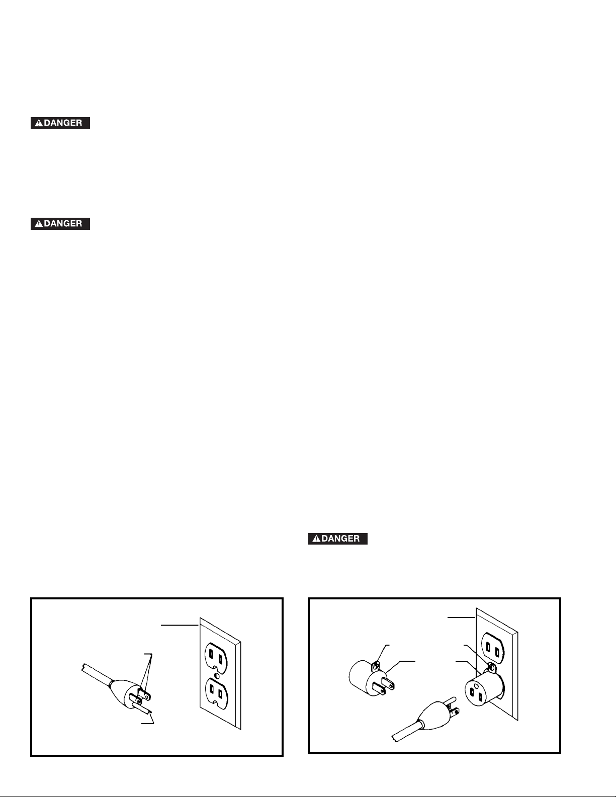
1. All grounded, cord-connected machines:
In the event of a malfunction or breakdown, grounding
provides a path of least resistance for electric current to
reduce the risk of electric shock. This machine is
equipped with an electric cord having an equipmentgrounding conductor and a grounding plug. The plug must
be plugged into a matching outlet that is properly installed
and grounded in accordance with all local codes and
ordinances.
Do not modify the plug provided - if it will not fit the outlet,
have the proper outlet installed by a qualified electrician.
Improper connection of the equipment-grounding
conductor can result in risk of electric shock. The
conductor with insulation having an outer surface that is
green with or without yellow stripes is the equipmentgrounding conductor. If repair or replacement of the
electric cord or plug is necessary, do not connect the
equipment-grounding conductor to a live terminal.
Check with a qualified electrician or service personnel if
the grounding instructions are not completely
understood, or if in doubt as to whether the machine is
properly grounded.
Use only 3-wire extension cords that have 3-prong
grounding type plugs and matching 3-conductor
receptacles that accept the machine’s plug, as shown in
Fig. A.
Repair or replace damaged or worn cord immediately.
POWER CONNECTIONS
MOTOR SPECIFICATIONS
Your machine is wired for 120 volts, 60 HZ alternating current. Before connecting the machine to the power source,
make sure the switch is in the “OFF” position.
GROUNDING INSTRUCTIONS
THIS MACHINE MUST BE GROUNDED WHILE IN USE TO PROTECT THE OPERATOR FROM
ELECTRIC SHOCK.
Page 7
77
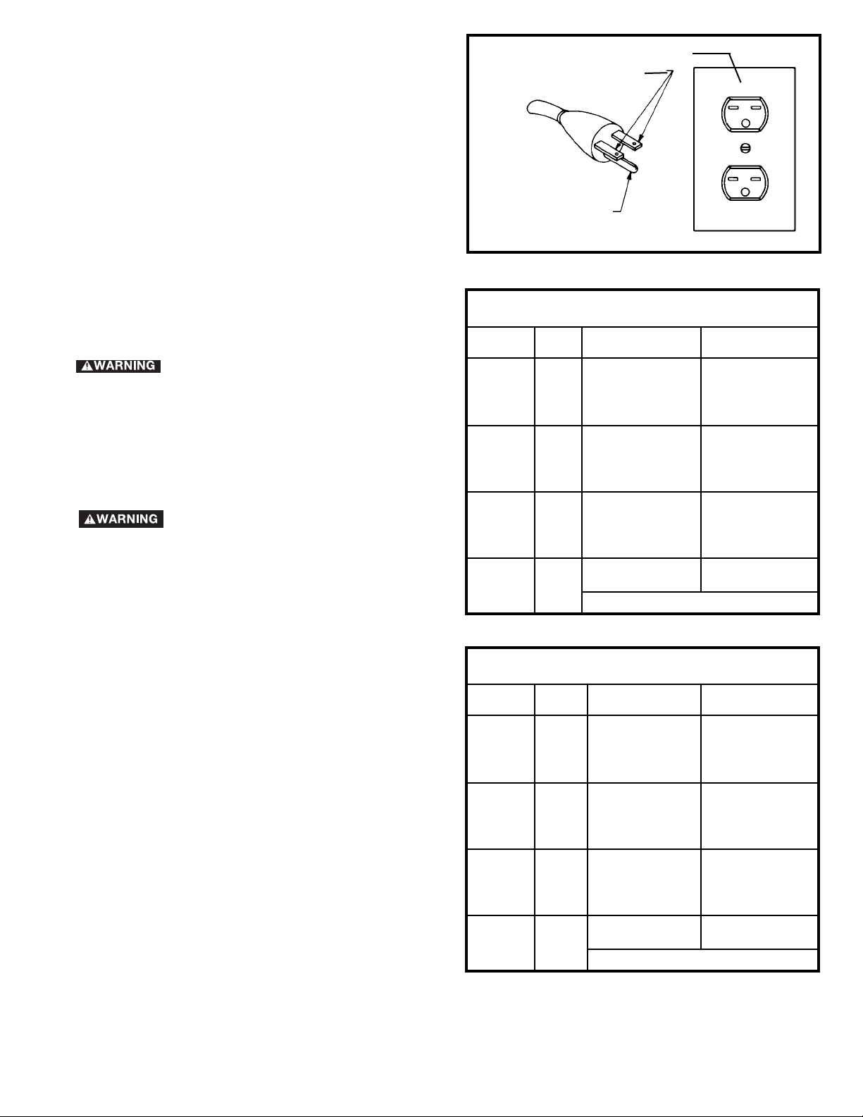
3. 240 VOLT SINGLE PHASE OPERATION
The motor supplied with your machine is a dual voltage,
120/240 volt motor. It is shipped ready-to-run for 120
volt operation. However, it can be converted for 240 volt
operation.
A qualified electrician should do the conversion, or the
machine can be taken to an Authorized Delta Service
Center. When completed, the machine must conform to
the National Electric Code and all local codes and
ordinances.
The machine is converted by re-wiring the motor for 240
volts, installing a 240 volt plug on the power supply cord
and replacing the switch with one that is rated for 240
volt operation.
Be sure the 240 volt plug is only used in an outlet having
the same configuration as the plug illustrated in Fig. C.
No adapter should be used with the 240 volt plug.
IN ALL CASES, MAKE CERTAIN THAT
THE RECEPTACLE IN QUESTION IS PROPERLY
GROUNDED. IF YOU ARE NOT SURE, HAVE A
QUALIFIED ELECTRICIAN CHECK THE
RECEPTACLE.
Fig. C
GROUNDED OUTLET BOX
CURRENT
CARRYING
PRONGS
GROUNDING BLADE
IS LONGEST OF THE 3 BLADES
EXTENSION CORDS
Use proper extension cords. Make sure
your extension cord is in good condition and is a 3-wire
extension cord which has a 3-prong grounding type
plug and matching receptacle which will accept the
machine’s plug. When using an extension cord, be sure
to use one heavy enough to carry the current of the
machine. An undersized cord will cause a drop in line
voltage, resulting in loss of power and overheating. Fig.
D-1 or D-2, shows the correct gauge to use depending
on the cord length. If in doubt, use the next heavier
gauge. The smaller the gauge number, the heavier the
cord.
Fig. D-1
Fig. D-2
MINIMUM GAUGE EXTENSION CORD
RECOMMENDED SIZES FOR USE WITH STATIONARY ELECTRIC MACHINES
Ampere Total Length Gauge of
Rating Volts of Cord in Feet Extension Cord
0-6 120
up to
25 18 AWG
0-6 120 25-50 16 AWG
0-6 120 50-100 16 AWG
0-6 120 100-150 14 AWG
6-10 120
up to
25 18 AWG
6-10 120 25-50 16 AWG
6-10 120 50-100 14 AWG
6-10 120 100-150 12 AWG
10-12 120
up to
25 16 AWG
10-12 120 25-50 16 AWG
10-12 120 50-100 14 AWG
10-12 120 100-150 12 AWG
12-16 120
up to
25 14 AWG
12-16 120 25-50 12 AWG
12-16 120
GREATER THAN 50 FEET NOT RECOMMENDED
MINIMUM GAUGE EXTENSION CORD
RECOMMENDED SIZES FOR USE WITH STATIONARY ELECTRIC MACHINES
Ampere Total Length Gauge of
Rating Volts of Cord in Feet Extension Cord
0-6 240
up to
50 18 AWG
0-6 240 50-100 16 AWG
0-6 240 100-200 16 AWG
0-6 240 200-300 14 AWG
6-10 240
up to
50 18 AWG
6-10 240 50-100 16 AWG
6-10 240 100-200 14 AWG
6-10 240 200-300 12 AWG
10-12 240
up to
50 16 AWG
10-12 240 50-100 16 AWG
10-12 240 100-200 14 AWG
10-12 240 200-300 12 AWG
12-16 240
up to
50 14 AWG
12-16 240 50-100 12 AWG
12-16 240
GREATER THAN 100 FEET NOT RECOMMENDED
Page 8
8
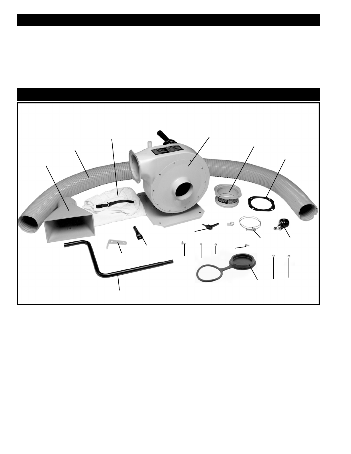
Fig. 2
1. Dust collector
2. Hose
3. Dust bag
4. Exhaust flange
5. Exhaust flange gasket
6. Intake funnel
7. Intake support angle brace
8. Upper support bracket
9. Lower tube support
10. Casters (4)
11. Lower tube support clamps (2)
12. Adjustable locking lever
13. Hose clamps (2)
14. 5/16-18x5/8" Button head carriage bolt (2)
15. 5/16" Lockwasher
16. 5/16-18 Flange hex nut (6)
17. 5/16-18x5/8" Hex head screw (4)
18. Intake cap
19. M8.4 Flat washer
20. 3/8-16 Flange Hex nut (4)
1
2
3
4
5
6
7
8
9
10
11
12
13
14
16
17
15
UNPACKING AND CLEANING
Carefully unpack the machine and all loose items from the shipping container(s). Remove the protective coating from
all unpainted surfaces. This coating may be removed with a soft cloth moistened with kerosene (do not use acetone,
gasoline or lacquer thinner for this purpose). After cleaning, cover the unpainted surfaces with a good quality household
floor paste wax.
CARTON CONTENTS
18
19
20
FOREWORD
The Delta ShopMaster Model AP300 is a portable single stage dust collector.
FUNCTIONAL DESCRIPTION
NOTICE: THE PHOTO ON THE MANUAL COVER ILLUSTRATES THE CURRENT PRODUCTION
MODEL. ALL OTHER ILLUSTRATIONS CONTAINED IN THE MANUAL ARE REPRESENTATIVE ONLY
AND MAY NOT DEPICT THE ACTUAL COLOR, LABELING OR ACCESSORIES AND ARE INTENDED
TO ILLUSTRATE TECHNIQUE ONLY.
Page 9
9
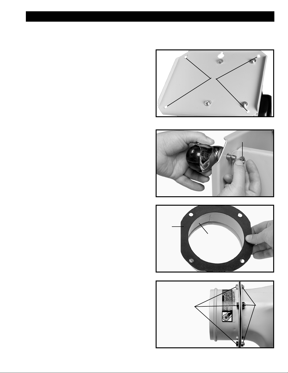
CASTERS
1. Place the dust collector on its side.
2. Insert bolt on caster through the four holes (A)
Fig. 3 in the base of the dust collector.
3. Thread a 3/8-16 flange hex nut (B) Fig. 4 onto each
of the four bolts and tighten securely.
Fig. 3
A
Fig. 4
B
EXHAUST FLANGE
1. Align the holes in the exhaust flange (A) Fig. 5 with
the holes in the exhaust flange gasket (B).
2. Insert a 5/16-18x5/8" hex head bolt thru the exhaust
flange, exhaust flange gasket and the base unit as
shown in Fig. 6.
3. Thread a 5/16-18 hex nut (B) onto the 5/16-18x5/8"
hex head bolt (A) Fig. 6 and tighten securely.
4. Repeat this process for the three remaining bolts.
Fig. 5
A
B
Fig. 6
A
B
ASSEMBLY
1. 1/2” & 9/16" Open or Box End Wrench - not provided
2. 1/2” &
9/16" Socket and Drive - not provided
3.
Flat or Phillips Screwdriver - not provided
ASSEMBLY TIME ESTIMATE 1-2 hrs.
ASSEMBLY TOOLS REQUIRED
Page 10
10
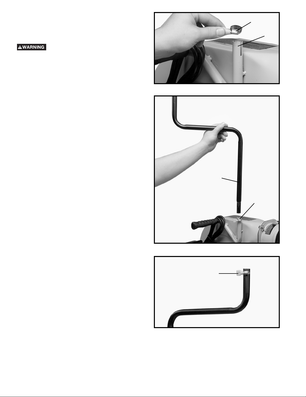
DUST PORT TUBE AND
CONNECTOR TO DUST COLLECTOR
BODY
Disconnect machine from power source!
1. Place tube clamp (A) Fig. 7 on the lower support
tube holder (B).
2. Insert the lower tube support (A) into the tube
support holder (B) as shown in Fig. 8.
3. Place a tube clamp (A) onto the lower tube support
as shown in Fig. 9.
Fig. 7
A
B
Fig. 8
A
B
Fig. 9
A
Page 11
11
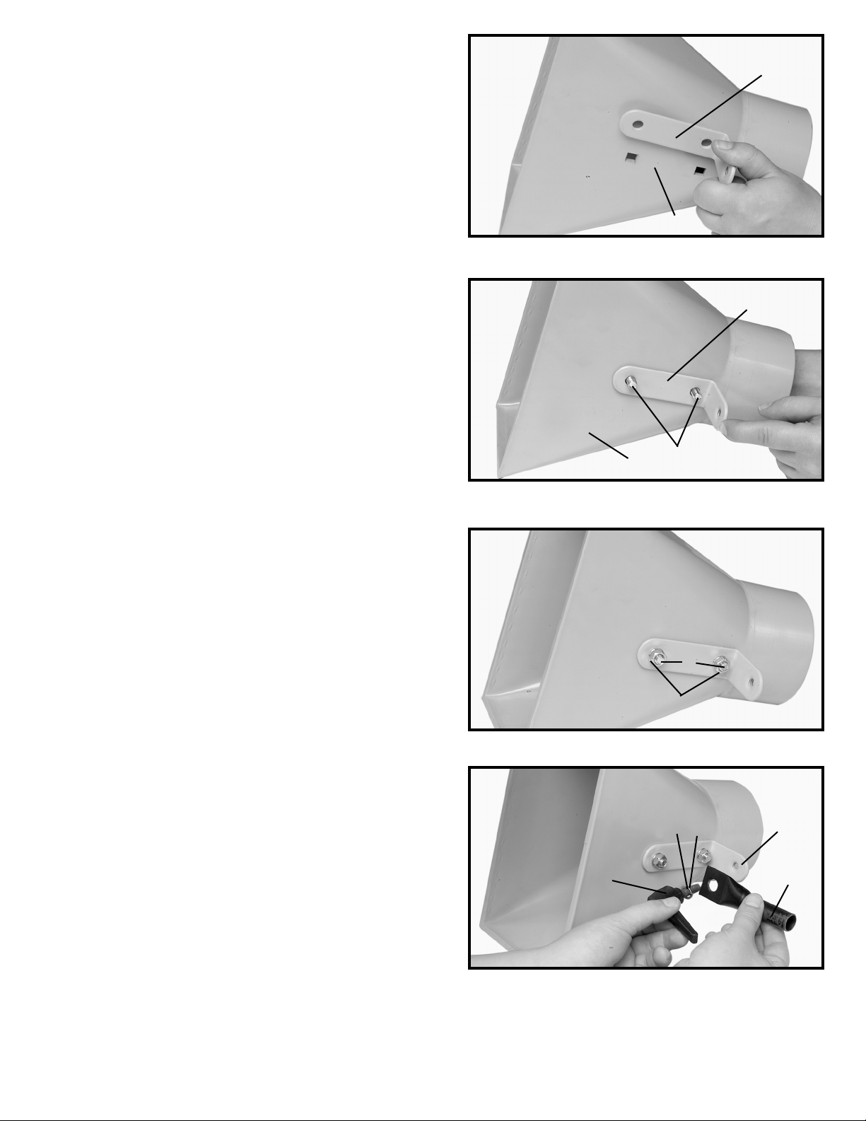
4. Align the two holes in the intake support angle brace
(A) Fig. 10 with the two holes in the intake funnel (B).
5. Fasten the intake support angle brace to the intake
funnel by inserting the two 5/16-18x5/8" button
head carriage bolts (C) thru the intake funnel (B) and
the intake support angle brace (A) as shown in Fig.
11.
6. Thread a 5/16-18" flange hex nut (C) Fig. 12 onto
the bolt (B) and tighten securely.
7. Attach the upper support bracket (B) Fig. 13 to the
intake support angle brace (C) with the adjustable
locking lever (D). NOTE: PLACE A M8.4 FLAT
WASHER (E) AND A 5/16” LOCKWASHER (F) FIG.
13, ONTO LOCKING LEVER SCREW BEFORE
ATTACHING TO THE INTAKE SUPPORT ANGLE
BRACE.
Fig. 10
A
B
Fig. 11
B
A
C
Fig. 12
B
C
Fig. 13
B
C
D
E
F
Page 12

12
VACUUM HOSE TO
DUST COLLECTOR
Disconnect machine from power source!
1. Place the intake cap holder (D) on the dust collector
as shown in Fig. 15. NOTE: DO NOT COVER THE
INTAKE PORT WITH THE INTAKE CAP WHEN
ATTACHING THE HOSE TO THE INTAKE PORT.
2. Place hose clamp (A) Fig. 15, onto one end of
vacuum hose (B) and slide hose around intake port
(C) as shown in Fig. 16. Tighten hose clamp (A).
8. Place intake funnel assembly (A), onto lower support
tube (B) Fig. 14, and secure with tube clamp (C).
Fig. 14
A
B
C
Fig. 15
Fig. 16
D
A
C
B
A
C
Page 13

13
Fig. 17
Fig. 18
Fig. 19
Fig. 20
3. Place the remaining hose clamp (A) Fig. 17, around
the other end of hose (B), slide hose (B) onto intake
funnel (C), and tighten hose clamp (A). NOTE: If
desired, intake funnel (C) can be rotated to the
vertical position, as shown in Fig. 18.
DUST BAG TO DUST COLLECTOR
Disconnect machine from power source!
Loosely thread end of dust bag strap (A) through clamp
(B) as shown in Fig. 19. Place open end of dust bag (C)
Fig. 19, over outlet flange (D) Fig. 20 and firmly pull strap
(A) to fasten dust collection bag to outlet flange.
A
B
C
C
A
B
C
D
A
Page 14

14
STARTING AND STOPPING
DUST COLLECTOR
1. The on/off switch (A) Fig. 24 is located on the front
of the machine. To turn the machine “ON”, move the
switch up to the “ON” position.
2. To turn the machine “OFF”, move the switch (A)
down to the “OFF” position.
MAKE SURE THAT THE SWITCH IS IN
THE “OFF” POSITION BEFORE
PLUGGING IN THE POWER CORD. IN THE EVENT OF A
POWER FAILURE, MOVE THE SWITCH TO THE “OFF”
POSITION. AN ACCIDENTAL START-UP CAN CAUSE
INJURY.
LOCKING SWITCH IN
THE “OFF” POSITION
IMPORTANT: When the machine is not in use, the
switch should be locked in the “OFF” position to
prevent unauthorized use. To lock the machine, grasp
the switch toggle (B) Fig. 25, and pulling it out of the
switch as shown. With the switch toggle (B) removed,
the switch will not operate. However, should the switch
toggle be removed while the machine is running, it can
be turned “OFF” once, but cannot be restarted without
re-inserting the switch toggle (B).
Fig. 24
Fig. 25
A
B
OPERATION
For operator safety, make certain the dust intake port is covered with the hose before operating the machine.
The rotating fan inside the blower housing is accessible through the dust intake port and is hazardous. Make sure intake cap
covers the intake port when hose is removed. Always wear proper apparel. Do not wear jewelry and keep fingers and all foreign
objects out of the dust intake port. Always follow the safety rules of this manual.
OPERATIONAL CONTROLS AND ADJUSTMENTS
Page 15

15
This versatile dust collector is light, compact and can
easily be transported for use in and out of the workshop.
This dust collector can be used with many different
types of woodworking machinery as shown in Figs. 26,
27, and 28. .
Fig. 26 illustrates the dust collector used with a router.
Note that the intake port is adjusted so that dust created
by the router will be collected.
Fig. 27 illustrates the dust collector used with a table
saw. Note that the intake port is removed from the lower
tube support. The intake funnel can be clamped to a tool
as shown.
Fig. 28 illustrates the dust collector used with a drum
sander that is equipped with a dust removal port. The 4"
hose can be connected directly to the dust removal port.
Fig. 26
Fig. 27
Fig. 28
MACHINE USE
Page 16

16
TROUBLESHOOTING
TRANSPORTATION AND STORAGE
1. The dust collector features a convenient carrying
handle with rubber grip (A) Fig. 29, which allows the
unit to be carried easily from one job area to another.
IMPORTANT: THE DUST COLLECTOR WEIGHS
APPROXIMATELY 46 LBS. CARE SHOULD BE
TAKEN WHEN LIFTING AND TRANSPORTING THE
MACHINE.
2. In addition to the carrying handle, the machine
features a storage mounting bracket (B) Fig. 30, with
a hole for mounting the dust collector to a wall or
wooden support when not in use.
Fig. 29
Fig. 30
A
B
For assistance with your machine, visit our website at www
.deltamachinery.com
for a list of service centers or call
the DELTA Machinery help line at 1-800-223-7278 (In Canada call 1-800-463-3582).
Page 17

17
Before any maintenance or service is performed, be sure the dust collector is disconnected from the
power source to prevent accidental starting. All maintenance other than the items recommended in this manual should
be performed by an authorized Delta Service Center.
1. Always disconnect the machine from the power source before performing any maintenance
procedures.
2. The condition of the dust bag should be checked periodically for damage and emptied on a regular basis. Do not
transport the machine with a full dust bag.
3. Clean and apply a dry silicone lubricant monthly to the impeller to remove any dirt or build-up of pitch, gum and
wood shavings.
4. Always make sure that the intake cap (A) Fig. 31, covers the intake port when the hose is not
connected to the machine.
Fig. 31
A
MAINTENANCE
KEEP MACHINE CLEAN
Periodically blow out all air passages with dry compressed
air. All plastic parts should be cleaned with a soft damp
cloth. NEVER use solvents to clean plastic parts. They could
possibly dissolve or otherwise damage the material.
Wear ANSI Z87.1 safety glasses while
using compressed air.
FAILURE TO START
Should your machine fail to start, check to make sure the
prongs on the cord plug are making good contact in the
outlet. Also, check for blown fuses or open circuit breakers
in the line.
Page 18

18
PARTS, SERVICE OR WARRANTY ASSISTANCE
All Delta Machines and accessories are manufactured to high quality standards and are serviced by a network
of Porter-Cable • Delta Factory Service Centers and Delta Authorized Service Stations. To obtain additional
information regarding your Delta quality product or to obtain parts, service, warranty assistance, or the location
of the nearest service outlet, please call 1-800-223-7278 (In Canada call 1-800-463-3582).
A complete line of accessories is available from your Delta Supplier, Porter-Cable • Delta Factory Service Centers,
and Delta Authorized Service Stations. Please visit our Web Site www.deltamachinery.com for a catalog or
for the name of your nearest supplier.
Since accessories other than those offered by Delta have not been tested
with this product, use of such accessories could be hazardous. For safest operation, only
Delta recommended accessories should be used with this product.
ACCESSORIES
Two Year Limited New Product Warranty
Delta will repair or replace, at its expense and at its option, any new Delta machine, machine part, or machine accessory
which in normal use has proven to be defective in workmanship or material, provided that the customer returns the product
prepaid to a Delta factory service center or authorized service station with proof of purchase of the product within two
years and provides Delta with reasonable opportunity to verify the alleged defect by inspection. For all refurbished Delta
product, the warranty period is 180 days. Delta may require that electric motors be returned prepaid to a motor
manufacturer’s authorized station for inspection and repair or replacement. Delta will not be responsible for any asserted
defect which has resulted from normal wear, misuse, abuse or repair or alteration made or specifically authorized by
anyone other than an authorized Delta service facility or representative. Under no circumstances will Delta be liable for
incidental or consequential damages resulting from defective products. This warranty is Delta’s sole warranty and sets
forth the customer’s exclusive remedy, with respect to defective products; all other warranties, express or implied, whether
of merchantability, fitness for purpose, or otherwise, are expressly disclaimed by Delta.
SERVICE
WARRANTY
Page 19

19
1919
Para obtener más información sobre Delta Machinery,
visite nuestro sitio web en: www.deltamachinery.com
Para las piezas, el servicio, la garantía o la otra ayuda
llaman por favor
1-800-223-7278 (en la llamada 1-800-463-3582 de Canada).
MANUAL DE INSTRUCCIONES
Recolector de Polvo Portátil de
Etapa Sencilla
(Modelo AP300)
PIEZA NO. A05734 - 12-17-04
Copyright © 2004 Delta Machinery
ENGLISH: PAGE 1
Page 20

20
Lea y entienda todas advertencias y las instrucciones operadoras antes de utilizar cualquier instrumento o el equipo.
Cuando se usa instrumentos o equipo, las precauciones básicas de la seguridad siempre se deben seguir para reducir el riesgo de la herida
personal. La operación impropia, la conservación o la modificación de instrumentos o equipo podrían tener como resultado el daño grave
de la herida y la propiedad. Hay ciertas aplicaciones para que equipaas con herramienta y el equipo se diseña. La Delta Machinery
recomienda totalmente que este producto no sea modificado y/o utilizado para ninguna aplicación de otra manera que para que se diseñó.
Si usted tiene cualquiera pregunta el pariente a su aplicación no utiliza el producto hasta que usted haya escrito Delta Machinery y nosotros
lo hemos aconsejado.
La forma en línea del contacto en www. deltamachinery. com
El Correo Postal: Technical Service Manager
Delta Machinery
4825 Highway 45 North
Jackson, TN 38305
(IN CANADA: 125 Mural St. Suite 300, Richmond Hill, ON, L4B 1M4)
Información con respecto a la operación segura y apropiada de este instrumento está disponible de las fuentes siguientes:
Power Tool Institute
1300 Sumner Avenue, Cleveland, OH 44115-2851
www
.powertoolinstitute.org
National Safety Council
1121 Spring Lake Drive, Itasca, IL 60143-3201
American National Standards Institute, 25 West 43rd Street, 4 floor, New York, NY 10036 www.ansi.org
ANSI 01.1Safety Requirements for Woodworking Machines, and
the U.S. Department of Labor regulations www
.osha.gov
Indica una situación de inminente riesgo, la cual, si no es evitada, causará la muerte o lesiones serias.
Indica una situación potencialmente riesgosa, que si no es evitada, podría resultar en la muerte o lesiones
serias.
Indica una situación potencialmente peligrosa, la cual, si no es evitada, podría resultar en lesiones menores o
mode-radas.
Usado sin el símbolo de seguridad de alerta indica una situa-ción potencialmente riesgosa la que, si no es
evitada, podría causar daños en la propiedad.
PAUTAS DE SEGURIDAD/DEFINICIONES
Algunos tipos de aserrín creados por máquinas eléctricas de lijado, aserrado, amolado, perforado u otras
actividades de la construcción, contienen materiales químicos conocidos (en el Estado de California) como causantes de cáncer, defectos
de nacimiento u otros daños del aparato reproductivo. Algunos ejemplos de dichos productos químicos son:
● El plomo contenido en algunas pinturas con base de plomo
● Sílice cristalizado proveniente de los ladrillos, el cemento y otros productos de albañilería
● Arsénico y cromo de madera tratada químicamente
Su riesgo por causa de estas exposiciones varía, dependiendo de con cuánta frecuencia realice este tipo de trabajo. Para reducir
su exposición a estos agentes químicos: trabaje en un área bien ventilada y trabaje con equipo de seguridad aprobado, use siempre
protección facial o respirador NIOSH/OSHA aprobados cuando deba utilizar dichas herramientas.
Es importante para usted leer y entender este manual. La información que lo contiene relaciona a proteger SU
SEGURIDAD y PREVENIR los PROBLEMAS. Los símbolos debajo de son utilizados para ayudarlo a reconocer esta
información.
INSTRUCCIONES DE SEGURIDAD IMPORTANTES
GUARDE ESTAS INSTRUCCIONES!
PROPOSICIÓN DE CALIFORNIA 65
Page 21

21
NORMAS GENERALES DE SEGURIDAD
1. PARA SU PROPIA SEGURIDAD, LEA EL MANUAL DE
INSTRUCCIONES ANTES DE UTILIZAR LA MÁQUINA.
Al aprender la aplicación, las limitaciones y los peligros
específicos de la máquina, se minimizará enormemente la
posibilidad de accidentes y lesiones.
2. USE PROTECCIÓN DE LOS OJOS Y DE LA AUDICIÓN.
USE SIEMPRE ANTEOJOS DE SEGURIDAD. Los lentes
de uso diario NO son anteojos de seguridad. USE EQUIPO
DE SEGURIDAD CERTIFICADO. El equipo de protección
de los ojos debe cumplir con las normas ANSI Z87.1. El
equipo de protección de la audición debe cumplir con las
normas ANSI S3.19.
3. USE INDUMENTARIA ADECUADA. No use ropa holgada,
guantes, corbatas, anillos, pulseras u otras joyas que
podrían engancharse en las piezas móviles. Se recomienda
usar calzado antideslizante. Use una cubierta protectora
del pelo para sujetar el pelo largo.
4. NO UTILICE LA MÁQUINA EN UN ENTORNO
PELIGROSO. La utilización de herramientas mecánicas en
lugares húmedos o mojados, o en la lluvia, puede causar
descargas eléctricas o electrocución. Mantenga bien
iluminada el área de trabajo para evitar tropezar o poner en
peligro los brazos, las manos y los dedos.
5. MANTENGA TODAS LAS HERRAMIENTAS Y
MÁQUINAS EN CONDICIONES ÓPTIMAS. Mantenga las
herramientas afiladas y limpias para lograr el mejor y más
seguro rendimiento. Siga las instrucciones de lubricación y
cambio de accesorios. Las herramientas y las máquinas
mal mantenidas pueden dañar más la herramienta o la
máquina y/o causar lesiones.
6. COMPRUEBE SI HAY PIEZAS DAÑADAS. Antes de
utilizar la máquina, compruebe si hay piezas dañadas.
Compruebe la alineación de las piezas móviles, si las
piezas móviles se atascan, si hay piezas rotas y toda otra
situación que podría afectar su funcionamiento. Un
protector o cualquier otra pieza que presente daños debe
repararse o reemplazarse apropiadamente. Las piezas
dañadas pueden causar daños adicionales a la máquina
y/o lesiones.
7. MANTENGA LIMPIA EL ÁREA DE TRABAJO. Las áreas y
los bancos desordenados invitan a que se produzcan
accidentes.
8. MANTENGA ALEJADOS A LOS NIÑOS Y A LOS
VISITANTES. El taller es un entorno potencialmente
peligroso. Los niños y los visitantes pueden sufrir lesiones.
9. REDUZCA EL RIESGO DE UN ARRANQUE NO
INTENCIONADO. Asegúrese de que el interruptor esté en
la posición de apagado antes de enchufar el cable de
alimentación. En caso de un apagón, mueva el interruptor
a la posición de apagado. Un arranque accidental podría
causar lesiones.
10. UTILICE LOS PROTECTORES. Asegúrese de que todos
los protectores estén colocados en su sitio, sujetos
firmemente y funcionando correctamente para prevenir
lesiones.
11. QUITE LAS LLAVES DE AJUSTE Y DE TUERCA ANTES
DE ARRANCAR LA MÁQUINA. Las herramientas, los
pedazos de desecho y otros residuos pueden salir
despedidos a alta velocidad, causando lesiones.
12. UTILICE LA MÁQUINA ADECUADA. No fuerce una
máquina o un aditamento a hacer un trabajo para el que no
se diseñó. El resultado podría ser daños a la máquina y/o
lesiones.
13. UTILICE ACCESORIOS RECOMENDADOS. La utilización
de accesorios y aditamentos no recomendados por Delta
podría causar daños a la máquina o lesiones al usuario.
14. UTILICE EL CORDÓN DE EXTENSIÓN ADECUADO.
Asegúrese de que el cordón de extensión esté en buenas
condiciones. Cuando utilice un cordón de extensión,
asegúrese de utilizar un cordón que sea lo suficientemente
pesado como para llevar la corriente que su producto
tome. Un cordón de tamaño insuficiente causará una caída
de la tensión de la línea, lo cual producirá una pérdida de
potencia y recalentamiento. Consulte el Cuadro de
cordones de extensión para obtener el tamaño correcto
dependiendo de la longitud del cordón y la capacidad
nominal en amperios indicada en la placa de
especificaciones. En caso de duda, utilice el próximo
calibre más grueso. Cuanto más pequeño sea el número
de calibre, más pesado será el cordón.
15. SUJETE FIRMEMENTE LA PIEZA DE TRABAJO. Utilice
abrazaderas o un tornillo de carpintero para sujetar la pieza
de trabajo cuando resulte práctico. La pérdida de control
de una pieza de trabajo puede causar lesiones.
16. HAGA AVANZAR LA PIEZA DE TRABAJO CONTRA EL
SENTIDO DE ROTACIÓN DE LA HOJA, EL CORTADOR
O LA SUPERFICIE ABRASIVA. Si la hace avanzar desde
el otro sentido, el resultado será que la pieza de trabajo
salga despedida a alta velocidad.
17. NO FUERCE LA PIEZA DE TRABAJO SOBRE LA
MÁQUINA. El resultado podría ser daños a la máquina y/o
lesiones.
18. NO INTENTE ALCANZAR DEMASIADO LEJOS. Una
pérdida del equilibrio puede hacerle caer en una máquina
en funcionamiento, causándole lesiones.
19. NO SE SUBA NUNCA A LA MÁQUINA. Se podrían
producir lesiones si la herramienta se inclina o si usted
hace contacto accidentalmente con la herramienta de
corte.
20. NO DEJE NUNCA DESATENDIDA LA MÁQUINA
CUANDO ESTÉ EN MARCHA. APÁGUELA. No deje la
máquina hasta que ésta se detenga por completo. Un niño
o un visitante podría resultar lesionado.
21. APAGUE LA MÁQUINA Y DESCONÉCTELA DE LA
FUENTE DE ALIMENTACIÓN antes de instalar o quitar
accesorios, antes de ajustar o cambiar configuraciones o
al realizar reparaciones. Un arranque accidental puede
causar lesiones.
22. HAGA SU TALLER A PRUEBA DE NIÑOS CON
CANDADOS E INTERRUPTORES MAESTROS O
QUITANDO LAS LLAVES DE ARRANQUE. El arranque
accidental de una máquina por un niño o un visitante
podría causar lesiones.
23. MANTÉNGASE ALERTA, FÍJESE EN LO QUE ESTÁ
HACIENDO Y USE EL SENTIDO COMÚN. NO UTILICE
LA MÁQUINA CUANDO ESTÉ CANSADO O BAJO LA
INFLUENCIA DE DROGAS, ALCOHOL O MEDICAMENTOS. Un momento de distracción mientras se estén
utilizando herramientas mecánicas podría causar lesiones.
24. EL USO DE ESTA HERRAMIENTA
PUEDE GENERAR Y DISPERSAR
POLVO U OTRAS PARTÍCULAS SUSPENDIDAS EN EL
AIRE, INCLUYENDO POLVO DE MADERA, POLVO DE
SÍLICE CRISTALINA Y POLVO DE ASBESTO. Dirija las
partículas de modo que se alejen de la cara y del cuerpo.
Utilice siempre la herramienta en un área bien ventilada y
proporcione un medio apropiado de remoción de polvo.
Use un sistema de recolección de polvo en todos los
lugares donde sea posible. La exposición al polvo puede
causar lesiones respiratorias graves y permanentes u otras
lesiones graves y permanentes, incluyendo silicosis (una
enfermedad pulmonar grave), cáncer y muerte. Evite
aspirar el polvo y evite el contacto prolongado con el
polvo. Si se permite que el polvo entre en la boca o en los
ojos, o que se deposite en la piel, se puede promover la
absorción de material nocivo. Use siempre protección
respiratoria aprobada por NIOSH/OSHA que se ajuste
apropiadamente y sea adecuada para la exposición al
polvo, y lávese las áreas expuestas con agua y jabón.
SI NO SE SIGUEN ESTAS NORMAS, EL RESULTADO PODRÍA SER LESIONES GRAVES.
Page 22

22
EL NO ACATAR ESTAS REGLAS PUEDE TENER COMO RESULTADO GRAVES LESIONES FISICAS
UTILICE el colector de polvo para recoger
materiales de madera solamente. NO utilice el colector
de polvo para recoger virutas metálicas, polvo metálico
o piezas metálicas.
NUNCA utilice el colector de polvo
para disipar vapores o humo. NUNCA recoja nada que
esté ardiendo o desprendiendo humo, como cigarrillos,
fósforos o cenizas calientes.
1. NO UTILICE ESTA MÁQUINA hasta que esté
completamente montada e instalada de acuerdo con
las instrucciones.
2. OBTENGA ASESORAMIENTO de su supervisor,
instructor u otra persona calificada si no está
completamente familiarizado con la utilización de esta
máquina.
3. SIGA TODOS LOS CÓDIGOS DE CABLEADO y las
conexiones eléctricas recomendadas.
4. NO tire del colector de polvo por el cable de
alimentación. NUNCA deje que el cable de
alimentación entre en contacto con bordes afilados,
superficies calientes, aceite o grasa. No ponga
nada encima del cable de alimentación.
5. Ponga SIEMPRE todos los controles en la posición
de apagado antes de desenchufar el colector de
polvo. PARA REDUCIR EL RIESGO DE
DESCARGAS ELÉCTRICAS, no utilice la unidad
sobre superficies mojadas. No la exponga a la
lluvia. Guárdela en interiores.
6. NO utilice la unidad con ninguna abertura
bloqueada; manténgala libre de polvo, pelusa, pelo
y todo aquello que pueda reducir la circulación de
aire.
7. NO utilice el colector de polvo para recoger líquidos
inflamables o combustibles, como por ejemplo
gasolina. NUNCA utilice el colector de polvo cerca
de líquidos inflamables o combustibles.
8. NO introduzca los dedos ni objetos extraños en el
orificio de entrada de polvo. Mantenga el pelo, la
ropa holgada, los dedos y todas las partes del
cuerpo alejados de las aberturas y las piezas
móviles del colector de polvo.
9. NUNCA utilice el colector de polvo sin la bolsa de
recolección de polvo colocada en su sitio y sujeta
adecuadamente.
10. INSPECCIONE PERIÓDICAMENTE la bolsa para
polvo con el fin de comprobar si tiene cortes,
roturas o desgarraduras. NUNCA utilice el colector
de polvo con una bolsa o manguera de aspiración
dañada.
11. Utilice SIEMPRE la cubierta de la entrada para
cubrir el orificio para polvo cuando el colector de
polvo no esté en uso o montado en una superficie
de soporte para almacenamiento.
12. NO deje el colector de polvo enchufado en el
tomacorriente eléctrico. Desenchufe el colector de
polvo del tomacorriente cuando no se esté
utilizando y antes de hacerle servicio, cambiar las
bolsas, desatascarlo y limpiarlo.
13. NUNCA utilice el colector de polvo con una bolsa o
manguera de aspiración dañada. INSPECCIONE
PERIÓDICAMENTE la bolsa para polvo con el fin
de comprobar si tiene cortes, roturas o
desgarraduras.
14. REEMPLACE inmediatamente un cable de
alimentación dañado. NO utilice un cable de
alimentación o enchufe dañado. Si el colector de
polvo no funciona correctamente, o si ha sufrido
daños, se ha dejado a la intemperie o ha estado en
contacto con agua, llévelo a un Centro de Servicio
Autorizado para que le den servicio.
15. APAGUE LA MÁQUINA Y DESCONÉCTELA de la
fuente de alimentación antes de instalar o quitar
accesorios, antes de ajustar o cambiar las
preparaciones o al hacer reparaciones.
16. APAGUE LA MÁQUINA, desconéctela de la fuente de
alimentación y limpie la mesa/área de trabajo antes de
dejar la máquina. BLOQUEE EL INTERRUPTOR EN LA
POSICIÓN DE APAGADO para impedir el uso no
autorizado.
GUARDE ESTAS INSTRUCCIONES.
Refiérase a ellas con frecuencia
y utilícelas para adiestrar a otros.
NORMAS ESPECÍFICAS ADICIONALES DE SEGURIDAD
Page 23

23
Debe utilizarse un circuito eléctrico independiente para las máquinas. Este circuito debe tener alambre de no menos
del No. 12 y debe estar protegido con un fusible de acción retardada de 20 A. Si se utiliza un cordón de extensión,
utilice únicamente cordones de extensión de tres alambres que tengan enchufes de tipo de conexión a tierra con tres
terminales y un receptáculo coincidente que acepte el enchufe de la máquina. Antes de conectar el máquina a la línea
de alimentación, asegúrese de que el interruptor(s) esté en la posición de apagado y cerciórese de que la corriente
eléctrica tenga las mismas características que las que estén indicadas en la máquina. Todas las conexiones a la línea
de alimentación deben hacer buen contacto. El funcionamiento a bajo voltaje dañará el máquina.
NO EXPONGA LA MÁQUINA A LA LLUVIA NI LA UTILICE EN LUGARES HÚMEDOS.
1. Todas las máquinas conectadas con cordón
conectadas a tierra:
En caso de mal funcionamiento o avería, la conexión a
tierra proporciona una ruta de resistencia mínima para la
corriente eléctrica, con el fin de reducir el riesgo de
descargas eléctricas. Esta máquina está equipada con
un cordón eléctrico que tiene un conductor de conexión
a tierra del equipo y un enchufe de conexión a tierra. El
enchufe debe enchufarse en un tomacorriente
coincidente que esté instalado y conectado a tierra
adecuadamente, de acuerdo con todos los códigos y
ordenanzas locales.
No modifique el enchufe suministrado. Si el enchufe no
cabe en el tomacorriente, haga que un electricista
calificado instale el tomacorriente apropiado.
La conexión inapropiada del conductor de conexión a
tierra del equipo puede dar como resultado riesgo de
descargas eléctricas. El conductor con aislamiento que
tiene una superficie exterior de color verde con o sin
franjas amarillas es el conductor de conexión a tierra del
equipo. Si es necesario reparar o reemplazar el cordón
eléctrico o el enchufe, no conecte el conductor de
conexión a tierra del equipo a un terminal con corriente.
Consulte a un electricista competente o a personal de
servicio calificado si no entiende completamente las
instrucciones de conexión a tierra o si tiene dudas en
cuanto a si la máquina está conectada a tierra
apropiadamente.
Utilice únicamente cordones de extensión de tres
alambres que tengan enchufes de tipo de conexión a
tierra con tres terminales y receptáculos de tres
conductores que acepten el enchufe de la máquina, tal
como se muestra en la Fig. A.
Repare o reemplace inmediatamente los cordones
dañados o desgastados.
2. Máquinas conectadas con cordón conectadas a
tierra diseñadas para utilizarse en un circuito de
alimentación que tenga una capacidad nominal de
menos de 150 V:
Si la máquina está diseñada para utilizarse en un circuito
que tenga un tomacorriente parecido al que se ilustra en
la Fig. A, la máquina tendrá un enchufe de conexión a
tierra que se parece al enchufe ilustrado en la Fig. A.
Puede utilizarse un adaptador temporal, que se parece
al adaptador ilustrado en la Fig. B, para conectar este
enchufe a un receptáculo coincidente de dos
conductores, tal como se muestra en la Fig. B, si no se
dispone de un tomacorriente conectado a tierra
apropiadamente. El adaptador temporal debe utilizarse
solamente hasta que un electricista calificado pueda
instalar un tomacorriente conectado a tierra
apropiadamente. La orejeta, lengüeta, etc., rígida de
color verde que sobresale del adaptador debe
conectarse a una toma de tierra permanente, como por
ejemplo una caja tomacorriente conectada a tierra
adecuadamente. Siempre que se utilice un adaptador,
debe sujetarse en su sitio con un tornillo de metal.
NOTA: En Canadá, el uso de un adaptador temporal
no está permitido por el Código Eléctrico
Canadiense.
EN TODOS LOS CASOS, ASEGÚRESE DE
QUE EL RECEPTÁCULO EN CUESTIÓN ESTÉ
CONECTADO A TIERRA ADECUADAMENTE. SI NO ESTÁ
SEGURO, HAGA QUE UN ELECTRICISTA CALIFICADO
COMPRUEBE EL RECEPTÁCULO.
CONEXIONES A LA FUENTE DE ALIMENTACIÓN
ESPECIFICACIONES DEL MOTOR
La máquina está cableada para corriente alterna de 120 V, 60 Hz. Antes de conectar la máquina a la fuente de
alimentación, asegúrese de que el interruptor esté en la posición de apagado.
INSTRUCCIONES DE CONEXIÓN A TIERRA
ESTA MÁQUINA DEBE ESTAR CONECTADA A TIERRA MIENTRAS SE ESTÉ UTILIZANDO, PARA PROTEGER
AL OPERADOR CONTRA LAS DESCARGAS ELÉCTRICAS.
Fig. A
Fig. B
CAJA TOMACORRIENTE
CONECTADA A TIERRA
TERMINALES
QUE LLEVAN
CORRIENTE
EL TERMINAL DE CONEXIÓN A
TIERRA ES EL MÁS LARGO DE
LOS 3 TERMINALES
MEDIO DE CONEXIÓN
TIERRA
ADAPTADOR
CAJA TOMACORRIENTE
CONECTADA A TIERRA
Page 24

24
Utilice cordones de extensión apropiados. Asegúrese de
que el cordón de extensión esté en buenas condiciones
y de que sea un cordón de extensión de tres alambres
que tenga un enchufe de tipo de conexión a tierra con
tres terminales y un receptáculo coincidente que acepte
el enchufe de la máquina. Cuando utilice un cordón de
extensión, asegúrese de emplear un cordón que sea lo
suficientemente pesado como para llevar la corriente de
la máquina. Un cordón de tamaño insuficiente causará
una caída de la tensión de la línea eléctrica que dará
como resultado pérdida de potencia y recalentamiento.
En la Fig. D1 o D2 se muestra el calibre correcto que
debe utilizarse dependiendo de la longitud del cordón.
En caso de duda, utilice el siguiente calibre más pesado.
Cuanto más pequeño sea el número de calibre, más
pesado será el cordón.
Fig. D1
CORDÓN DE EXTENSIÓN DE CALIBRE MÍNIMO
TAMAÑOS RECOMENDADOS PARA USO CON MÁQUINAS ELÉCTRICAS ESTACIONARIAS
Capacidad Longitud Total Del Calibre Del Cordon
Nominal En Voltios Cordon De Extensión
Amperios En Pies
0-6 120
Hasta
25 18 AWG
0-6 120 25-50 16 AWG
0-6 120 50-100 16 AWG
0-6 120 100-150 14 AWG
6-10 120
Hasta
25 18 AWG
6-10 120 25-50 16 AWG
6-10 120 50-100 14 AWG
6-10 120 100-150 12 AWG
10-12 120
Hasta
25 16 AWG
10-12 120 25-50 16 AWG
10-12 120 50-100 14 AWG
10-12 120 100-150 12 AWG
12-16 120
Hasta
25 14 AWG
12-16 120 25-50 12 AWG
12-16 120
NO SE RECOMIENDA LONGITUDES MAYOR DE 50 PIES
Fig. D2
CORDÓN DE EXTENSIÓN DE CALIBRE MÍNIMO
TAMAÑOS RECOMENDADOS PARA USO CON MÁQUINAS ELÉCTRICAS ESTACIONARIAS
Capacidad Longitud Total Del Calibre Del Cordon
Nominal En Voltios Cordon De Extensión
Amperios En Pies
0-6 240
Hasta
50 18 AWG
0-6 240 50-100 16 AWG
0-6 240 100-200 16 AWG
0-6 240 200-300 14 AWG
6-10 240
Hasta
50 18 AWG
6-10 240 50-100 16 AWG
6-10 240 100-200 14 AWG
6-10 240 200-300 12 AWG
10-12 240
Hasta
50 16 AWG
10-12 240 50-100 16 AWG
10-12 240 100-200 14 AWG
10-12 240 200-300 12 AWG
12-16 240
Hasta
50 14 AWG
12-16 240 50-100 12 AWG
12-16 240
NO SE RECOMIENDA LONGITUDES MAYOR DE 100 PIES
CORDONES DE EXTENSIÓN
Fig. C
CAJA TOMACORRIENTE
CONECTADA A TIERRA
TERMINALES
QUE LLEVAN
CORRIENTE
EL TERMINAL DE CONEXIÓN A
TIERRA ES EL MÁS LARGO DE
LOS 3 TERMINALES
3. LA OPERACIÓN la MONOFÁSICO de 240 VOLTIOS
El motor provisto de su máquina es un voltaje dual,
motor de 120/240 voltio. Es ready-to-run enviado para
la operación de 120 voltios. Sin embargo, puede ser
convertida para la operación de 240 voltios.
Un electricista cualificado debe hacer la conversión, o la
máquina se puede llevar un centro de servicio
autorizado del delta. Cuando está terminada, la
máquina debe conformarse con el código eléctrico
nacional y todos los códigos y ordenanzas locales.
La máquina es convertida cambiando el motor a 240
voltios, instalando un enchufe de 240 voltios a la cuerda
de la fuente de alimentación y substituyendo el
interruptor por una que sea clasificado para la operación
de 240 voltios.
Sea seguro que el enchufe de 240 voltios está utilizado
solamente en un enchufe que tiene la misma
configuración que el enchufe ilustrado en Fig. C. Ningún
adaptador no se debe utilizar con el enchufe de 240
voltios.
En todos los casos, asegúrese que el
receptáculo en la pregunta esté puesto
a tierra correctamente. Si usted no es seguro, haga
que un electricista cualificado compruebe el
receptáculo.
Page 25

25
1. Colector de polvo
2. Manguera
3. Bolsa para polvo
4. Brida de la salida
5. Empaquetadura de la brida de la salida
6. Embudo de entrada
7. Angular del soporte de la entrada
8. Ménsula del soporte superior
9. Soporte del tubo inferior
10. Ruedecillas (4)
11. Abrazaderas del soporte del tubo inferior (2)
12. Palanca de fijación ajustable
13. Abrazaderas de manguera (2)
14. Perno de carruaje de cabeza semiesférica de 5/16-
18x5/8" (2)
15. Arandela de seguridad de 5/16"
16. Tuerca hexagonal reborde de 5/16" (6)
17. Tornillo de cabeza hexagonal de 5/16-18x5/8" (4)
18. Tapa de la entrada
19. M8.4 arandela Plana
20. Tuerca hexagonal reborde de 3/8" (4)
DESEMPAQUETADO Y LIMPIEZA
Desempaque cuidadosamente la máquina y todas las piezas sueltas que están en el contenedor o contenedores de
transporte. Quite el revestimiento protector de todas las superficies no pintadas. Este revestimiento puede quitarse
con un paño suave humedecido con queroseno (no utilice acetona, gasolina ni diluyente de laca para este fin).
Después de realizar la limpieza, cubra las superficies no pintadas con una cera en pasta doméstica de buena calidad
para pisos.
CONTENIDO DE CARTON
DESCRIPCIÓN FUNCIONAL
NOTA: LA FOTO DE LA CUBIERTA DEL MANUAL ILUSTRA EL MODELO DE PRODUCCIÓN ACTUAL.
TODAS LAS DEMÁS ILUSTRACIONES SON SOLAMENTE REPRESENTATIVAS Y ES POSIBLE QUE NO
MUESTREN EL COLOR, EL ETIQUETADO Y LOS ACCESORIOS REALES.
PROLOGO
El delta ShopMaster AP300 modelo es solo colector de polvo portable de la etapa.
Fig. 2
1
2
3
4
5
6
7
8
9
10
11
12
13
14
16
17
15
18
19
20
Page 26

Fig. 3
A
Fig. 4
Fig. 5
A
B
Fig. 6
A
B
RUEDECILLAS
1. Coloque el colector de polvo sobre uno de sus
lados.
2. Introduzca un perno de ruedecilla a través de los
cuatro agujeros (A), Fig. 3, que están en la base del
colector de polvo.
3. Enrosque una tuerca hexagonal reborde (B), Fig. 4,
en la cabeza de cada uno de los cuatro pernos y
apriétela firmemente.
DE LA BRIDA DE LA SALIDA
1. Alinee los agujeros de la brida de la salida (A), Fig.
5, con los agujeros que están en la empaquetadura
de la brida de la salida (B).
2. Introduzca un perno de cabeza hexagonal de 5/1618x5/8" a través de la brida de la salida, la
empaquetadura de la brida de la salida y la unidad
de la base, de la manera que se muestra en la Fig.
6.
3. Enrosque una tuerca hexagonal de 5/16" (B) en el
perno de cabeza hexagonal de 5/16-18x5/8" (A),
Fig. 6, y apriétela firmemente.
4. Repita este proceso para los tres pernos restantes.
B
HERRAMIENTAS DE ENSAMBLAJE REQUERIDAS
ENSAMBLAJE
1. 1/2” & 9/16" Abierto o la Caja Termina la Llave Inglesa - no
proporcionó
2. 1/2” & 9/16" Enchufe y Maneja - no proporcionó
3. Plano o el Destornillador de Phillips - no proporcionó
ESTIMACIÓN DEL TIEMPO DE
ENSAMBLAJE
1-2 hrs.
26
Page 27

27
Fig. 7
A
B
Fig. 8
A
B
Fig. 9
A
DEL ORIFICIO PARA POLVO Y EL
CONECTOR EN EL CUERPO DEL
COLECTOR DE POLVO
1. Coloque la abrazadera de tubo (A), Fig. 7, sobre el
portatubo del soporte inferior (B).
2. Introduzca la ménsula del soporte del tubo (A) en el
portasoporte del tubo (B), de la manera que se muestra
en la Fig. 8.
3. Coloque una abrazadera de tubo (A) sobre el
soporte del tubo inferior, de la manera que se muestra
en la Fig. 9.
Page 28

282828
Fig. 10
A
B
Fig. 11
B
A
C
Fig. 12
B
C
Fig. 13
4. Alinee los dos agujeros del anclaje del angular del
soporte de la entrada (A), Fig. 10, con los dos
agujeros del embudo de entrada (B).
5. Sujete el anclaje del angular del soporte de la
entrada al embudo de entrada introduciendo los dos
pernos de carruaje de cabeza semiesférica de 5/1618x5/8" (C) a través del embudo de entrada (B) y el
anclaje del angular del soporte de la entrada (A), de
la manera que se muestra en la Fig. 11.
6. Enrosque una tuerca hexagonal reborde de 5/16" (C)
Fig. 12 en el perno (B) y apriétela firmemente.
7. Sujete la ménsula del soporte superior (B), Fig. 13, al
angular del soporte de la entrada (C) con la palanca
de fijación ajustable (D). NOTA: COLOQUE UNA
M8.4 ARANDELA PLANA (E) ARANDELA DE
SEGURIDAD DE 5/16" (F), FIG. 13, EN EL
TORNILLO DE LA PALANCA DE FIJACIÓN ANTES
DE REALIZAR LA SUJECIÓN AL ANGULAR DEL
SOPORTE DE LA ENTRADA.
B
C
D
E
F
Page 29

29
Fig. 14
A
B
C
Fig. 15
Fig. 16
D
A
C
B
A
C
DE UNA MANGUERA DE
ASPIRACIÓN EN EL
COLECTOR DE POLVO
1. Coloque el soporte de la tapa de la entrada (D)
sobre el colector de polvo de la manera que se
muestra en la Fig. 15. NOTA: NO CUBRA EL
ORIFICIO DE ENTRADA CON LA TAPA DE LA
ENTRADA CUANDO ACOPLE LA MANGUERA AL
ORIFICIO DE ENTRADA.
2. Coloque la abrazadera de manguera (A), Fig. 15, en
un extremo de la manguera de aspiración (B) y
deslice la manguera alrededor del conector (C), de
la manera que se muestra en la Fig. 16. Apriete la
abrazadera de manguera (A).
8. Coloque el tubo de soporte inferior (B), Fig. 14,
sobre el conjunto del embudo de entrada (A) y sujételo
con la abrazadera de tubo (C).
Page 30

303030
Fig. 17
Fig. 18
Fig. 19
Fig. 20
A
B
C
C
A
B
C
D
A
3. Coloque la abrazadera de manguera restante (A),
Fig. 17, alrededor del otro extremo de la manguera
de aspiración (B), deslice la manguera (B) sobre el
embudo de entrada (C) y apriete la abrazadera de
manguera (A). NOTA: Si lo desea, el embudo de
entrada (C) puede girarse hasta la posición vertical,
de la manera que se muestra en la Fig. 18.
DE LA BOLSA PARA POLVO EN EL
COLECTOR DE POLVO
Inserte flojamente el extremo de la correa de la bolsa
para polvo (A) a través de la abrazadera (B) de la manera
que se muestra en la Fig. 19. Coloque el extremo abierto
de la bolsa para polvo (C), Fig. 19, sobre la brida de la
salida (D), Fig. 20, y tire firmemente de la correa (A) para
sujetar la bolsa de recolección de polvo a la brida de la
salida.
Page 31

31
Fig. 24
Fig. 25
A
B
Antes de utilizar la máquina, para seguridad del operator, asegúrese de que el orificio de entrada de
polvo está cubierto con la manguera de aspiración. El ventilador que gira en el interior de la carcasa del soplador es
accesible a través del orificio de entrada de polvo y es peligroso. Asegúrese de que la tapa de la entrada cubra el orificio
de entrada cuando se haya quitado la manguera. Use siempre indumetaria adecuada. No use alhajas y mantenga los dedos
y todos los objetos extra
ños fuera del orificio de entrada de polvo. Siga siempre las normas de seguridad de ests manual..
ARRANQUE Y PARADA DEL
COLECTOR DE POLVO
1. El interruptor on/apagado. (A) la Fig. 24 está situada
en el frente de la máquina. Para dar vuelta a ON de
la máquina, mueva el interruptor hasta la posición
de ON.
2. Para dar vuelta a OFF de la máquina, baje el
interruptor (a) a la posición de OFF.
CERCIÓRESE QUE EL
INTERRUPTOR ESTÁ EN EL
“LEJOS” LA POSICIÓN ANTES DE CONECTAR LA
CUERDA DEL PODER. EN CASO DE UN FALLO DEL
SUMINISTRO ELÉCTRICO, MUEVA EL
INTERRUPTOR AL “LEJOS” LA POSICIÓN. UNA
COMPANIA NUEVA ACCIDENTAL PUEDE CAUSAR
LA HERIDA.
FIJACIÓN DEL INTERRUPTOR EN
LA POSICIÓN DE APAGADO
IMPORTANTE: Cuándo la herramienta no es
adentro uso, el interruptor se debe bloquear en el
OFF posición para prevenir uso desautorizado. Esto
puede hacerse tomando la pieza acodada (B) y
removiéndolo por completo del interruptor, tal como se
ilustra en la Fig. 25. El interruptor no funcionará sin la
pieza acodada (B). No obstante, si se quita la pieza
acodada mientras que la sierra está funcionando, ésta
puede ser apagada una vez, pero no puede volver a
arrancar sin la inserción de la pieza acodada (B).
OPERACIÓN
CONTROLES Y AJUSTES OPERACIONALES
Page 32

32
Fig. 26
Fig. 27
Fig. 28
Este versátil colector de polvo es liviano y compacto, y
puede transportarse fácilmente a diversas ubicaciones
para utilizarse dentro y fuera del taller. Este colector de
polvo puede utilizarse con muchos tipos distintos de
maquinaria de elaboración de la madera, tal como se
muestra en las Figs. 26, 27 y 28. Este colector de polvo
muestra su versatilidad en la forma en que el orificio de
entrada puede posicionarse para acomodar distintos
tipos de maquinaria de elaboración de la madera.
En la Fig. 26 se ilustra el colector de polvo utilizado en
combinación con una fresadora. Observe que el orificio
de entrada está ajustado de manera que podrá
recolectar el polvo generado al utilizar la fresadora.
En la Fig. 27 se ilustra el colector de polvo utilizado en
combinación con una sierra de mesa. Observe que el
orificio de entrada se ha quitado del soporte del tubo
inferior. El embudo de entrada puede sujetarse con
abrazaderas a una herramienta para proporcionar
recolección de polvo de la manera que se muestra en la
ilustración.
En la Fig. 28 se ilustra el colector de polvo utilizado en
combinación con una lijadora de tambor que está
equipada con un orificio de remoción de polvo. Se
puede quitar el embudo de entrada y conectar el tubo
para polvo de 4 pulgadas directamente al orificio de
remoción de polvo.
UTILIZAR LA MAQUINA
Page 33

33
Fig. 29
Fig. 30
A
B
TRANSPORTE Y ALMACENAMIENTO
1. El colector de polvo cuenta con una práctica asa de
transporte con una empuñadura de goma (A), Fig.
29, que permite transportar fácilmente la unidad de
un área de trabajo a otra. IMPORTANTE: EL
COLECTOR DE POLVO PESA
APROXIMADAMENTE 46 LB. DEBE TENERSE
CUIDADO AL LEVANTAR Y TRANSPORTAR LA
MÁQUINA.
2. Además del asa de transporte, la máquina cuenta
con un soporte de montaje de almacenamiento (B),
Fig. 30, con un agujero para montar el colector de
polvo en una pared o un soporte de madera (cuando
no se esté utilizando).
Page 34

MANTENGA LAS HERRAMIENTAS
LIMPIAS
Periódicamente sople todos los conductos de
ventilación con aire seco a presión. Todas las partes de
plástico deben ser limpiadas con una tela suave y
húmeda. NUNCA use solventes para limpiar las partes
de plástico. Es posible que puedan disolver o de otra
manera dañar el material.
USE ANSI Z87.1 ANTEOJOS DE
SEGURIDAD CUANDO USE AIRE A PRESIÓN.
FALLA DE PONERSE EN MARCHA
Si su herramienta falla de ponerse en marcha, revísela
para asegurarse de que los contactos de la clavija estén
en buen contacto con el tomacorriente. También, vea si
hay fusibles fundidos o ruptores abiertos en el circuito.
34
MANTENIMIENTO
LOCALIZACION DE FALLAS
Para obtener asistencia para su máquina, visite nuestro sitio Web en www.deltamachinery
.com
para tener acceso
a una lista de centros de servicio o llame a la línea de ayuda de Delta Machinery al 1-800-223-7278. (En Canadá,
llame al 1-800-463-3582.)
Fig. 31
A
Antes de que se realice cualquier mantenimiento o servicio, asegúrese de que el colector de polvo
esté desconectado de la fuente de alimentación para evitar un arranque accidental. Todo mantenimiento que no se
relacione con los artículos recomendados en este manual debe ser realizado por un Centro de Servicio Delta
autorizado.
1. Desconecte siempre la máquina de la fuente de alimentación antes de realizar cualquier
procedimiento de mantenimiento.
2. El estado de la bolsa para polvo debe comprobarse periódicamente para ver si hay daños, y la bolsa debe vaciarse
de forma periódica. No transporte la máquina con una bolsa para polvo llena.
3. Limpie el impulsor y aplíquele un lubricante de silicona seco mensualmente para quitar toda la suciedad o
acumulación de resina, goma y virutas de madera.
4. Asegúrese siempre de que la tapa de la entrada (A), Fig. 31, cubra el orificio de entrada cuando
la manguera no esté conectada a la máquina.
Page 35

35
SERVICIO
PIEZAS, SERVICIO O ASISTENCIA DE GARANTÍA
Todas las máquinas y accesorios Delta se fabrican conforme a altos estándares de calidad y reciben servicio de una red
de Centros de Servicio de Fábrica Porter-Cable • Delta y Estaciones de Servicio Autorizado Delta. Para obtener la
información adicional con respecto a su producto de calidad del delta o para obtener piezas, el servicio, la ayuda de la
garantía, o la localización del tomacorriente para servicio más cercano, llaman por favor 1-800-223-7278 (en la llamada 1800-463-3582 de Canadá).
Una línea completa de accesorios está disponible de su surtidor de Porter-Cable • Delta, centros de servicio de la fábrica
de Porter-Cable • Delta, y estaciones autorizadas delta. Visite por favor nuestro Web site www.deltamachinery.com
para un catálogo o para el nombre de su surtidor más cercano.
Puesto que los accesorios con excepción de ésos ofrecidos por Delta no
se han probado con este producto, el uso de tales accesorios podría ser peligroso. Para la
operación
más segura, solamente el delta recomendó los accesorios se debe utilizar con
este producto.
ACCESORIOS
GARANTIA
Garantía limitada de dos años para productos nuevos
Delta reparará o reemplazará, a expensas y opción propias, cualquier máquina nueva, pieza de máquina nueva o
accesorio de máquina nuevo Delta que durante el uso normal haya presentado defectos de fabricación o de material,
siempre que el cliente devuelva el producto con el transporte prepagado a un centro de servicio de fábrica Delta o una
estación de servicio autorizado Delta, con un comprobante de compra del producto, dentro del plazo de dos años y dé
a Delta una oportunidad razonable de verificar el supuesto defecto mediante la realización de una inspección. Para todos
los productos Delta reacondicionados, el período de garantía es de 180 días. Delta podrá requerir que los motores
eléctricos sean devueltos con el transporte prepagado a una estación autorizada de un fabricante de motores para ser
sometidos a inspección y reparación o para ser reemplazados. Delta no será responsable de ningún defecto alegado que
haya resultado del desgaste normal, uso indebido, abuso o reparación o alteración realizada o autorizada
específicamente por alguien que no sea un centro de servicio autorizado Delta o un representante autorizado Delta. Delta
no será responsable en ninguna circunstancia de los daños incidentales o emergentes que se produzcan como resultado
de productos defectuosos. Esta garantía es la única garantía de Delta y establece el recurso exclusivo del cliente en lo
que respecta a los productos defectuosos; Delta rechaza expresamente todas las demás garantías, expresas o implícitas,
tanto de comerciabilidad como de idoneidad para un propósito o de cualquier otro tipo.
Page 36

The following are trademarks of PORTER-CABLE •DELTA (Las siguientes son marcas registradas de PORTER-CABLE • DELTA S.A.) (Les marques
suivantes sont des marques de fabriquant de la PORTER-CABLE
•
DELTA): Auto-Set®, BAMMER®, B.O.S.S.®, Builder’s Saw®, Contractor’s Saw®,
Contractor’s Saw II™, Delta
®
, DELTACRAFT®, DELTAGRAM™, Delta Series 2000™, DURATRONIC™, Emc²™, FLEX®, Flying Chips™, FRAME SAW®,
Grip Vac™, Homecraft
®
, INNOVATION THAT WORKS®, Jet-Lock®, JETSTREAM®, ‘kickstand®, LASERLOC®, MICRO-SET®, Micro-Set®, MIDI LATHE®,
MORTEN™, NETWORK™, OMNIJIG
®
, POCKET CUTTER®, PORTA-BAND®, PORTA-PLANE®, PORTER-CABLE®&(design), PORTER-
CABLE
®
PROFESSIONAL POWER TOOLS, PORTER-CABLE REDEFINING PERFORMANCE™, Posi-Matic®, Q-3®&(design), QUICKSAND®&(design),
QUICKSET™, QUICKSET II
®
, QUICKSET PLUS™, RIPTIDE™&(design), SAFE GUARD II®, SAFE-LOC®, Sanding Center®, SANDTRAP®&(design), SAW
BOSS
®
, Sawbuck™, Sidekick®, SPEED-BLOC®, SPEEDMATIC®, SPEEDTRONIC®, STAIR EASE®, The American Woodshop®&(design), The Lumber
Company
®
&(design), THE PROFESSIONAL EDGE®, THE PROFESSIONAL SELECT®, THIN-LINE™, TIGER®, TIGER CUB®, TIGER SAW®,
TORQBUSTER
®
, TORQ-BUSTER®, TRU-MATCH™, TWIN-LITE®, UNIGUARD®, Unifence®, UNIFEEDER™, Unihead®, Uniplane™, Unirip®, Unisaw®,
Univise
®
, Versa-Feeder®, VERSA-PLANE®, WHISPER SERIES®, WOODWORKER’S CHOICE™.
Trademarks noted with ™ and ® are registered in the United States Patent and Trademark Office and may also be registered in other countries. Las
Marcas Registradas con el signo de ™ y ® son registradas por la Oficina de Registros y Patentes de los Estados Unidos y también pueden estar
registradas en otros países.
PORTER-CABLE • DELTA SERVICE CENTERS
(CENTROS DE SERVICIO DE PORTER-CABLE
• DELTA)
Parts and Repair Service for Porter-Cable •Delta Machinery are Available at These Locations
(Obtenga Refaccion de Partes o Servicio para su Herramienta en los Siguientes Centros de Porter-Cable
•
Delta)
Authorized Service Stations are located in many large cities. Telephone 800-438-2486 or 731-541-6042 for assistance locating one.
Parts and accessories for Porter-Cable
·
Delta products should be obtained by contacting any Porter-Cable·Delta Distributor, Authorized
Service Center, or Porter-Cable
·
Delta Factory Service Center. If you do not have access to any of these, call 800-223-7278 and you will
be directed to the nearest Porter-Cable·Delta Factory Service Center. Las Estaciones de Servicio Autorizadas están ubicadas en muchas
grandes ciudades. Llame al 800-438-2486 ó al 731-541-6042 para obtener asistencia a fin de localizar una. Las piezas y los accesorios
para los productos Porter-Cable
·
Delta deben obtenerse poniéndose en contacto con cualquier distribuidor Porter-Cable·Delta, Centro
de Servicio Autorizado o Centro de Servicio de Fábrica Porter-Cable·Delta. Si no tiene acceso a ninguna de estas opciones, llame al
800-223-7278 y le dirigirán al Centro de Servicio de Fábrica Porter-Cable
·
Delta más cercano.
ARIZONA
Phoenix 85013-2906
4501 N. 7th Ave.
Phone: (602) 279-6414
Fax: (602) 279-5470
CALIFORNIA
Ontario 91761 (Los Angeles)
3949A East Guasti Road
Phone: (909) 390-5555
Fax: (909) 390-5554
San Diego 92111
7290 Clairemont Mesa Blvd.
Phone: (858) 279-2011
Fax: (858) 279-0362
San Leandro 94577 (Oakland)
3039 Teagarden Street
Phone: (510) 357-9762
Fax: (510) 357-7939
COLORADO
Denver 80223
700 West Mississippi Ave.
Phone: (303) 922-8325
Fax: (303) 922-0245
FLORIDA
Davie 33314 (Miami)
4343 South State Rd. 7 (441)
Unit #107
Phone: (954) 321-6635
Fax: (954) 321-6638
Tampa 33634
4909 West Waters Ave.
Phone: (813) 884-0434
Fax: (813) 888-5997
GEORGIA
Forest Park 30297 (Atlanta)
5442 Frontage Road,
Suite 112
Phone: (404) 608-0006
Fax: (404) 608-1123
ILLINOIS
Addison 60101 (Chicago)
400 South Rohlwing Rd.
Phone: (630) 424-8805
Fax: (630) 424-8895
KANSAS
Overland Park 66214
9201 Quivira Road
Phone: (913) 495-4330
Fax: (913) 495-4378
MARYLAND
Elkridge 21075 (Baltimore)
7397-102 Washington Blvd.
Phone: (410) 799-9394
Fax: (410) 799-9398
MASSACHUSETTS
Franklin 02038 (Boston)
Franklin Industrial Park
101E Constitution Blvd.
Phone: (508) 520-8802
Fax: (508) 528-8089
MICHIGAN
Madison Heights 48071 (Detroit)
30475 Stephenson Highway
Phone: (248) 597-5000
Fax: (248) 597-5004
MINNESOTA
Eden Prairie 55344
9709 Valley View Road
Phone: (952) 884-9191
Fax: (952) 884-3750
MISSOURI
St. Louis 63146
11477 Page Service Drive
Phone: (314) 997-9100
Fax: (314) 997-9183
NEW YORK
Flushing 11365-1595 (N.Y.C.)
175-25 Horace Harding Expwy.
Phone: (718) 225-2040
Fax: (718) 423-9619
NORTH CAROLINA
Charlotte 28270
9129 Monroe Road, Suite 115
Phone: (704) 841-1176
Fax: (704) 708-4625
OHIO
Columbus 43229
1948 Schrock Road
Phone: (614) 895-3112
Fax: (614) 895-3187
Parma Heights OH 44130
6485 Pearl Road
Phone: (440) 842-9100
Fax: (440) 884-3430
OREGON
Portland 97230
14811 North East Airport Way
Phone: (503) 255-6556
Fax: (503) 255-6543
PENNSYLVANIA
Willow Grove 19090
(Philadelphia)
520 North York Road
Phone: (215) 658-1430
Fax: (215) 658-1433
TEXAS
Carrollton 75006 (Dallas)
1300 Interstate 35 N, Suite 112
Phone: (972) 446-2996
Fax: (972) 446-8157
Houston 77022-2122
536 East Tidwell Rd.
Phone: (713) 692-7111
Fax: (713) 692-1107
WASHINGTON
Auburn 98001(Seattle)
3320 West Valley HWY, North
Building D, Suite 111
Phone: (253) 333-8353
Fax: (253) 333-9613
PC7.2-0105-149
CANADIAN PORTER-CABLE • DELTA SERVICE CENTERS
ALBERTA
Bay 6, 2520-23rd St. N.E.
Calgary, Alberta
T2E 8L2
Phone: (403) 735-6166
Fax: (403) 735-6144
BRITISH COLUMBIA
8520 Baxter Place
Burnaby, B.C.
V5A 4T8
Phone: (604) 420-0102
Fax: (604) 420-3522
MANITOBA
1699 Dublin Avenue
Winnipeg, Manitoba
R3H 0H2
Phone: (204) 633-9259
Fax: (204) 632-1976
ONTARIO
505 Southgate Drive
Guelph, Ontario
N1H 6M7
Phone: (519) 767-4132
Fax: (519) 767-4131
QUÉBEC
1515 ave.
St-Jean Baptiste, Suite 160
Québec, Québec
G2E 5E2
Phone: (418) 877-7112
Fax: (418) 877-7123
1447, Begin
St-Laurent, (Montréal),
Québec
H4R 1V8
Phone: (514) 336-8772
Fax: (514) 336-3505
 Loading...