

Page 1

INSTRUCTION MANUAL
Air Cleaner
(Model AP200)
PART NO. 906565 - 07-18-02
Copyright © 2002 Delta Machinery
ESPAÑOL: PÁGINA 13
To learn more about DELTA MACHINERY
visit our website at: www.deltamachinery.com.
For Parts, Service, Warranty or other Assistance,
please call
1-800-223-7278 (In Canada call 1-800-463-3582).
Page 2

2
GENERAL SAFETY RULES
Woodworking can be dangerous if safe and proper operating procedures are not followed. As with all machinery, there
are certain hazards involved with the operation of the product. Using the machine with respect and caution will
considerably lessen the possibility of personal injury. However, if normal safety precautions are overlooked or ignored,
personal injury to the operator may result. Safety equipment such as guards, push sticks, hold-downs, featherboards,
goggles, dust masks and hearing protection can reduce your potential for injury. But even the best guard won’t make
up for poor judgment, carelessness or inattention. Always use common sense
and exercise caution in the workshop.
If a procedure feels dangerous, don’t try it. Figure out an alternative procedure that feels safer. REMEMBER: Your
personal safety is your responsibility.
This machine was designed for certain applications only. Delta Machinery strongly recommends that this machine not
be modified and/or used for any application other than that for which it was designed. If you have any questions relative
to a particular application, DO NOT use the machine until you have first contacted Delta to determine if it can or should
be performed on the product.
Technical Service Manager
Delta Machinery
4825 Highway 45 North
Jackson, TN 38305
(IN CANADA: 505 SOUTHGATE DRIVE, GUELPH, ONTARIO N1H 6M7)
WARNING: FAILURE TO FOLLOW THESE RULES MAY RESULT IN SERIOUS PERSONAL INJURY
1. FOR YOUR OWN SAFETY, READ INSTRUCTION
MANUAL BEFORE OPERATING THE TOOL. Learn the
tool’s application and limitations as well as the specific
hazards peculiar to it.
2. KEEP GUARDS IN PLACE and in working order.
3. ALWAYS WEAR EYE PROTECTION.
Wear safety
glasses. Everyday eyeglasses only have impact resistant
lenses; they are not safety glasses. Also use face or dust
mask if cutting operation is dusty. These safety glasses
must conform to ANSI Z87.1 requirements. NOTE:
Approved glasses have Z87 printed or stamped on them.
4. REMOVE ADJUSTING KEYS AND WRENCHES. Form
habit of checking to see that keys and adjusting wrenches
are removed from tool before turning it “on”.
5. KEEP WORK AREA CLEAN. Cluttered areas and
benches invite accidents.
6. DON’T USE IN DANGEROUS ENVIRONMENT. Don’t
use power tools in damp or wet locations, or expose them
to rain. Keep work area well-lighted.
7. KEEP CHILDREN AND VISITORS AWAY. All children
and visitors should be kept a safe distance from work area.
8. MAKE WORKSHOP CHILDPROOF – with padlocks,
master switches, or by removing starter keys.
9. DON’T FORCE TOOL. It will do the job better and be
safer at the rate for which it was designed.
10. USE RIGHT TOOL. Don’t force tool or attachment to
do a job for which it was not designed.
11. WEAR PROPER APPAREL. No loose clothing, gloves,
neckties, rings, bracelets, or other jewelry to get caught in
moving parts. Nonslip footwear is recommended. Wear
protective hair covering to contain long hair.
12. SECURE WORK. Use clamps or a vise to hold work
when practical. It’s safer than using your hand and frees
both hands to operate tool.
13. DON’T OVERREACH. Keep proper footing and
balance at all times.
14. MAINTAIN TOOLS IN TOP CONDITION. Keep tools
sharp and clean for best and safest performance. Follow
instructions for lubricating and changing accessories.
15. DISCONNECT TOOLS before servicing and when
changing accessories such as blades, bits, cutters, etc.
16. USE RECOMMENDED ACCESSORIES. The use of
accessories and attachments not recommended by Delta
may cause hazards or risk of injury to persons.
17. REDUCE THE RISK OF UNINTENTIONAL STARTING.
Make sure switch is in “OFF” position before plugging in
power cord.
In the event of a power failure, move switch
to the “OFF” position.
18. NEVER STAND ON TOOL. Serious injury could occur if
the tool is tipped or if the cutting tool is accidentally
contacted.
19. CHECK DAMAGED PARTS. Before further use of the
tool, a guard or other part that is damaged should be
carefully checked to ensure that it will operate properly and
perform its intended function – check for alignment of
moving parts, binding of moving parts, breakage of parts,
mounting, and any other conditions that may affect its
operation. A guard or other part that is damaged should be
properly repaired or replaced.
20. DIRECTION OF FEED. Feed work into a blade or
cutter against the direction of rotation of the blade or cutter
only.
21. NEVER LEAVE TOOL RUNNING UNATTENDED.
TURN POWER OFF. Don’t leave tool until it comes to a
complete stop.
22.
STAY ALERT, WATCH WHAT YOU ARE DOING, AND
USE COMMON SENSE WHEN OPERATING A POWER
TOOL. DO NOT USE TOOL WHILE TIRED OR UNDER
THE INFLUENCE OF DRUGS, ALCOHOL, OR
MEDICATION. A moment of inattention while operating
power tools may result in serious personal injury.
23. MAKE SURE TOOL IS DISCONNECTED FROM
POWER SUPPLY while motor is being mounted,
connected or reconnected.
24. THE DUST GENERATED by certain woods and wood
products can be injurious to your health. Always operate
machinery in well ventilated areas and provide for proper
dust removal. Use wood dust collection systems whenever
possible.
SAVE THESE INSTRUCTIONS.
Refer to them often and use them to instruct others.
Page 3

3
ADDITIONAL SAFETY RULES
FOR AIR CLEANERS
1. DANGER: DO NOT USE THIS UNIT TO FILTER METAL DUST. Combining wood and metal dust can create
an explosion or fire hazard. This unit is intended to filter non-explosive atmospheres only.
2. WARNING: DUST GENERATED BY CERTAIN WOODS AND WOOD PRODUCTS CAN BE HAZARDOUS TO
YOUR HEALTH.
3. WARNING: DO NOT USE THIS UNIT TO DISSIPATE FUMES OR SMOKE. This air cleaner is intended for use
where only dry airborne dust is present. Its use should be limited to non-explosive, non-metallic atmospheres.
4. DO NOT OPERATE THIS UNIT UNTIL IT IS COMPLETELY ASSEMBLED AND INSTALLED ACCORDING TO
THE INSTRUCTIONS.
5. OBTAIN ADVICE FROM YOUR SUPERVISOR, INSTRUCTOR, OR ANOTHER QUALIFIED PERSON if you are
not thoroughly familiar with the operation of this unit.
6. FOLLOW ALL WIRING CODES and recommended electrical connections.
7. DO NOT LIFT THIS UNIT BY THE POWER CORD. Do not use the power cord as a hanging device.
8. SECURELY ANCHOR THIS UNIT INTO A SUPPORTING STRUCTURE when suspending it from the ceiling.
Always keep a minimum of 7 feet between the bottom of the unit and the floor surface to allow for sufficient head
clearance. Use only a chain rated for a minimum of 150 lb. working load to adequately hold the unit. Use steel SHooks that are at least 1/4" in diameter to suspend the unit from the ceiling. Lag-type bolts used suspend the unit
from the ceiling must be threaded at least 1-1/2" into supporting structural members.
9. SUPPORT THIS UNIT OR SECURELY CLAMP IT TO THE WORK SURFACE WHEN IT IS USED IN A PORTABLE
APPLICATION to eliminate potential movement and/or damage from falling.
10. ENSURE THAT THE INTAKE AND EXHAUST AREAS ARE CLEAR PRIOR TO STARTING THE UNIT.
11. KEEP ARMS, HANDS, AND FINGERS AWAY FROM THE FAN. Avoid all exposure to rotating parts.
12. DO NOT OPERATE THIS UNIT WITHOUT THE FILTERS IN PLACE.
13. DO NOT ATTEMPT TO REMOVE OR REPLACE THE FILTER(S) WHILE THE UNIT IS RUNNING. Make certain
that the unit is disconnected from the power source.
14. MAINTAIN THE UNIT IN TOP CONDITION. Keep filters clean for optimum performance. Follow all instructions for
changing and cleaning filters.
15. STORE THIS UNIT IN A LOCATION that eliminates the potential of damage to the power cord. Safely store power
cord on the unit to eliminate tripping hazards.
16. TURN THE UNIT “OFF” AND DISCONNECT IT FROM THE POWER SOURCE before installing or removing
accessories, or when making repairs.
SAVE THESE INSTRUCTIONS.
Refer to them often
and use them to instruct others
.
Page 4
4
POWER CONNECTIONS
A separate electrical circuit should be used for your machines. This circuit should not be less than #12 wire and should
be protected with a 20 Amp time lag fuse. If an extension cord is used, use only 3-wire extension cords which have 3prong grounding type plugs and matching receptacle which will accept the machine’s plug. Before connecting the
motor to the power line, make sure the switch is in the “OFF” position and be sure that the electric current is of the
same characteristics as indicated on the machine. All line connections should make good contact. Running on low
voltage will damage the motor.
WARNING: DO NOT EXPOSE THE MACHINE TO RAIN OR OPERATE THE MACHINE IN DAMP LOCATIONS.
MOTOR SPECIFICATIONS
Your machine is wired for 120 volt, 60 HZ alternating current. Before connecting the machine to the power source,
make sure the switch is in the “OFF” position.
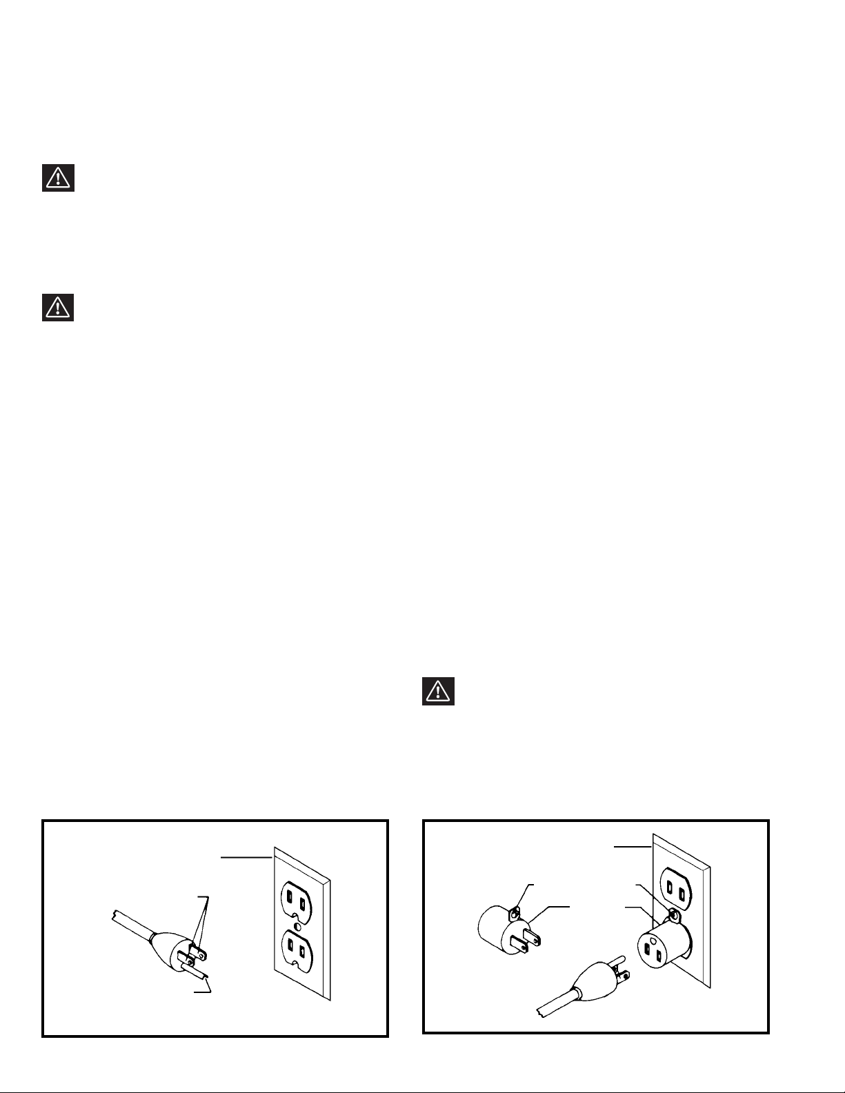
GROUNDING INSTRUCTIONS
WARNING: THIS MACHINE MUST BE GROUNDED WHILE IN USE TO PROTECT THE OPERATOR FROM
ELECTRIC SHOCK.
Fig. A Fig. B
GROUNDED OUTLET BOX
CURRENT
CARRYING
PRONGS
GROUNDING BLADE
IS LONGEST OF THE 3 BLADES
GROUNDED OUTLET BOX
GROUNDING
MEANS
ADAPTER
2. Grounded, cord-connected machines intended for use
on a supply circuit having a nominal rating less than 150
volts:
If the machine is intended for use on a circuit that has an
outlet that looks like the one illustrated in Fig. A, the
machine will have a grounding plug that looks like the plug
illustrated in Fig. A. A temporary adapter, which looks like
the adapter illustrated in Fig. B, may be used to connect
this plug to a matching 2-conductor receptacle as shown
in Fig. B if a properly grounded outlet is not available. The
temporary adapter should be used only until a properly
grounded outlet can be installed by a qualified electrician.
The green-colored rigid ear, lug, and the like, extending
from the adapter must be connected to a permanent
ground such as a properly grounded outlet box. Whenever
the adapter is used, it must be held in place with a metal
screw.
NOTE: In Canada, the use of a temporary adapter is not
permitted by the Canadian Electric Code.
WARNING: IN ALL CASES, MAKE CERTAIN THE
RECEPTACLE IN QUESTION IS PROPERLY
GROUNDED. IF YOU ARE NOT SURE HAVE A
QUALIFIED ELECTRICIAN CHECK THE RECEPTACLE.
1. All grounded, cord-connected machines:
In the event of a malfunction or breakdown, grounding
provides a path of least resistance for electric current to
reduce the risk of electric shock. This machine is
equipped with an electric cord having an equipmentgrounding conductor and a grounding plug. The plug must
be plugged into a matching outlet that is properly installed
and grounded in accordance with all local codes and
ordinances.
Do not modify the plug provided - if it will not fit the outlet,
have the proper outlet installed by a qualified electrician.
Improper connection of the equipment-grounding
conductor can result in risk of electric shock. The
conductor with insulation having an outer surface that is
green with or without yellow stripes is the equipmentgrounding conductor. If repair or replacement of the
electric cord or plug is necessary, do not connect the
equipment-grounding conductor to a live terminal.
Check with a qualified electrician or service personnel if
the grounding instructions are not completely
understood, or if in doubt as to whether the machine is
properly grounded.
Use only 3-wire extension cords that have 3-prong
grounding type plugs and matching 3-conductor
receptacles that accept the machine’s plug, as shown in
Fig. A.
Repair or replace damaged or worn cord immediately.
Page 5

Use proper extension cords. Make sure your extension cord is in good condition and is a 3-wire extension cord which
has a 3-prong grounding type plug and matching receptacle which will accept the machine’s plug. When using an
extension cord, be sure to use one heavy enough to carry the current of the machine. An undersized cord will cause
a drop in line voltage, resulting in loss of power and overheating. Fig. D, shows the correct gauge to use depending
on the cord length. If in doubt, use the next heavier gauge. The smaller the gauge number, the heavier the cord.
EXTENSION CORDS
OPERATING INSTRUCTIONS
FOREWORD
The Delta ShopMaster Model AP200 Air Cleaner is specifically designed to quietly circulate and filter non-metallic dust
which is generated throughout the work area. The Air Cleaner is furnished with two filters: a disposable outer filter which
filters out 98% of particles five microns in size; and the secondary filter will capture 85% of dust particles of one micron
in size (one micron = one millionth of a meter). Breathing microscopic particles can be a potential health hazard;
therefore, filtering out microscopic dust particles of the mentioned sizes will make for a cleaner and safer environment.
This Air Cleaner will filter the air in a room measuring 20’ x 20’ x 8’ sixteen times an hour. If desired, multiple units can
be used to filter larger areas.
UNPACKING AND CLEANING
Carefully unpack the machine and all loose items from the shipping container(s). Remove the protective coating from
all unpainted surfaces. This coating may be removed with a soft cloth moistened with kerosene (do not use acetone,
gasoline or lacquer thinner for this purpose). After cleaning, cover the unpainted surfaces with a good quality household
floor paste wax.
NOTICE: THE MANUAL COVER PHOTO ILLUSTRATES THE CURRENT
PRODUCTION MODEL. ALL OTHER ILLUSTRATIONS ARE REPRESENTATIVE
ONLY AND MAY NOT DEPICT THE ACTUAL COLOR, LABELING OR
ACCESSORIES AND MAY BE INTENDED TO ILLUSTRATE TECHNIQUE ONLY.
5
Fig. D
MINIMUM GAUGE EXTENSION CORD
RECOMMENDED SIZES FOR USE WITH STATIONARY ELECTRIC MACHINES
Ampere Total Length Gauge of
Rating Volts of Cord in Feet Extension Cord
0-6 115
up to
25 18 AWG
0-6 115 25-50 16 AWG
0-6 115 50-100 16 AWG
0-6 115 100-150 14 AWG
6-10 115
up to
25 18 AWG
6-10 115 25-50 16 AWG
6-10 115 50-100 14 AWG
6-10 115 100-150 12 AWG
10-12 115
up to
25 16 AWG
10-12 115 25-50 16 AWG
10-12 115 50-100 14 AWG
10-12 115 100-150 12 AWG
12-16 115
up to
25 14 AWG
12-16 115 25-50 12 AWG
12-16 115
GREATER THAN 50 FEET NOT RECOMMENDED
Page 6

6
AIR CLEANER PARTS
Fig. 2
1 - Air cleaner
2 - Four 5/16-18x1½" eye-bolts
3 - Four 5/16-18 flange nuts
4 - Four rubber feet
1
2
3
4
Page 7

7
ASSEMBLY INSTRUCTIONS
WARNING: FOR YOUR OWN SAFETY, DO NOT CONNECT THE MACHINE TO THE POWER SOURCE UNTIL
THE MACHINE IS COMPLETELY ASSEMBLED AND YOU READ AND UNDERSTAND THE ENTIRE INSTRUCTION
MANUAL.
The Air Cleaner requires very little assembly; therefore, determine in which position the Air Cleaner will be used - on
the floor, bench or overhead. If the Air Cleaner will be used as a mobile unit, proceed to “USING THE AIR CLEANER
ON A BENCH OR FLOOR SURFACE” section. If ceiling mounting, proceed to section “MOUNTING THE AIR
CLEANER TO A CEILING OR OVERHEAD SUPPORT.”
IMPORTANT: When determining a location to mount the air cleaner, the unit will operate more efficiently when
the air flow is unrestricted. Do not locate the unit in a corner or near any heating or cooling vents.
USING THE AIR CLEANER ON A BENCH OR
FLOOR SURFACE
1. Locate (4) self-adhesive rubber feet (D) Fig. 2,
supplied with the unit. Carefully place Air Cleaner on a
firm supporting surface so there is access to the bottom
of the cabinet as shown in Fig. 3. Apply one selfadhesive rubber pad, to bottom at each corner (A) Fig.
3, of air cleaner cabinet. The rubber feet will help
eliminate vibration and the possibility of the air cleaner
“walking” across the work or floor surface.
For operator safety, we suggest that the unit be
clamped down when used on a work bench or
positioned on sawhorses.
Fig. 3
A
2. There are two lifting handles located on each side of
the cabinet as shown in Fig. 4, to assist in carrying the
unit from one place to another. To avoid damage to the
air filters, carry the air cleaner with the filters positioned
away from your body. CAUTION: THIS MACHINE
WEIGHS APPROXIMATELY 50 POUNDS.
Fig. 4
Page 8

8
MOUNTING THE AIR CLEANER TO THE CEILING OR
OVERHEAD SUPPORT
WARNING: THIS TOOL WEIGHS APPROXIMATELY
50 POUNDS. MAKE CERTAIN THE UNIT IS SECURELY
SUPPORTED WHEN MOUNTING TO A CEILING OR
OVERHEAD SUPPORT.
1. Remove four screws, one of which is shown at (C)
Fig. 5, from the top of air cleaner (D).
2. Thread 5/16-18 flange nut (E) Fig. 5, approximately
half-way onto 5/16-18x1½" eye-bolt (F), as shown.
3. Thread eye-bolt (F) Fig. 5, into hole where screw (C)
was removed in STEP 1. NOTE: THREAD EYE-BOLTS
IN EIGHT COMPLETE TURNS.
4. Repeat this process for the three remaining holes in
the top of air cleaner
Fig. 5
C
D
E
F
Fig. 6
F
5. Fig. 6, illustrates the four eye-bolts (F) attached to
top of air cleaner. NOTE: To adjust the height of the air
cleaner, loosen flange nuts (E) Fig. 5, and rotate eyebolts as necessary. Eye-bolts must be threaded at
least eight complete turns into tapped hole in air
cleaner. Make certain the flange nuts (E) Fig. 5, are
tightened down against the surface of the air cleaner
after height adjustments are made.
When suspending the air cleaner from the ceiling or
other overhead support, make certain the supporting
hardware (not supplied) is securely anchored into a
wooden supporting structure as shown in Fig. 7.
WARNING: NEVER SECURE MOUNTING HARDWARE
TO DRYWALL, DROP CEILING TILE/FRAME, OR NONSTRUCTURAL MEMBERS.
Fig. 7
WARNING: Keep a minimum of seven feet
between bottom of air cleaner and the floor surface.
DO NOT use rope, cable or power cord to suspend
the unit from the ceiling. We recommend that a chain
should be used and rated for a minimum of a 150 lb.
working load to firmly support the air cleaner.
IMPORTANT: When determining a location to mount
the unit, the air cleaner will operate more efficiently
when the air flow is unrestricted. Do not locate the
unit in a corner or near any heating or cooling vents.
Page 9
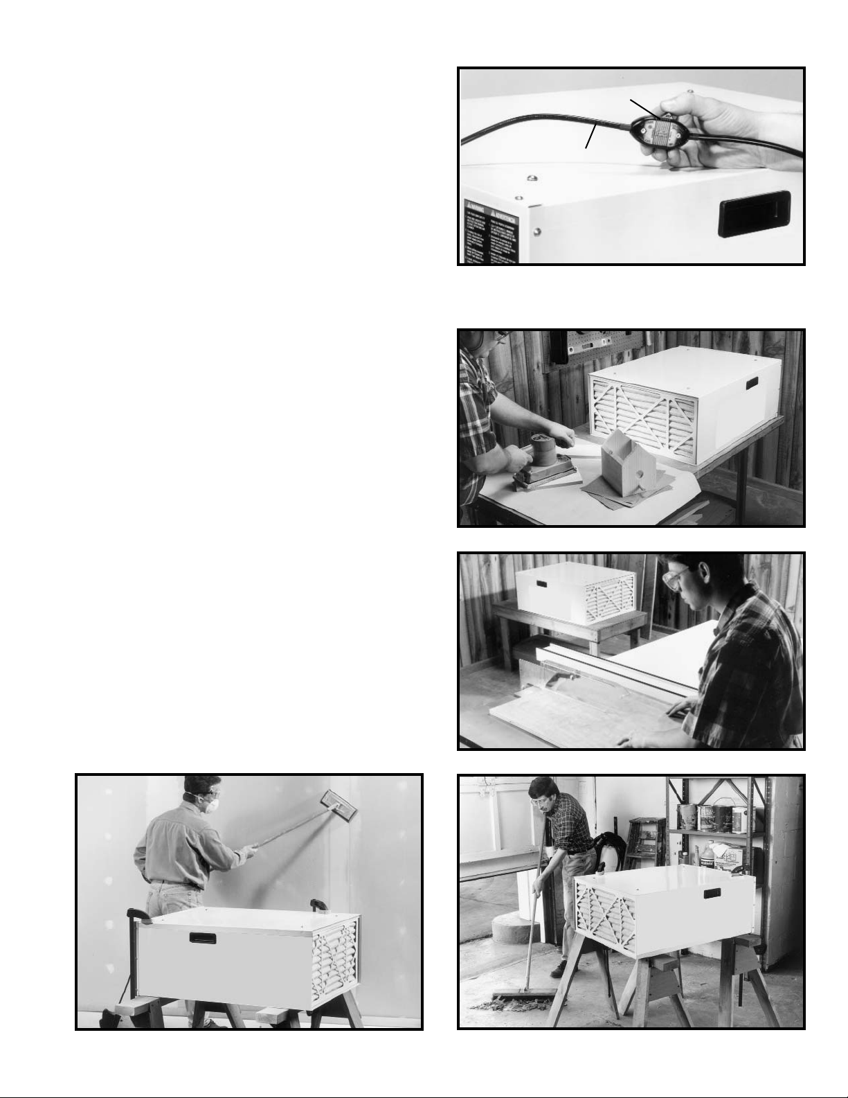
OPERATING CONTROLS
ON/OFF SWITCH
The Air Cleaner is equipped with an in-line rocker switch
(M) Fig.11, located on the power cord (N). To start or
stop the motor, press downward on the rocker switch.
NOTE: The switch has markings on the side to
determine the on/off position. We suggest that when
finished with the air cleaner, the switch be turned off
rather than unplugging the unit.
Fig. 11
M
N
OPERATIONS
1. NOTE: The air cleaner may produce a slight odor for
the first couple hours of operation due to the protective
coating which is applied to internal components. This
odor will dissipate and should be disregarded.
IMPORTANT: Never operate the air cleaner without
air filters in place.
2. Fig. 12 illustrates the air cleaner being used in benchtop sanding applications.
Fig. 12
Fig.13
Fig.15
3. Fig. 13 illustrates the air cleaner being used in circular
saw applications.
4. Figs. 14 and 15 illustrate the air cleaner being used
in dry wall and basement cleaning applications.
CAUTION: We recommend that the air cleaner be
clamped, as shown, if using sawhorses as a supporting
surface.
Fig.14
9
Page 10

10
Fig. 16
5. Fig. 16, illustrates the air cleaner being used in a
floor sanding application.
Fig. 17
6. Fig. 17, illustrates the air cleaner suspended from
wooden ceiling supports for overhead operation.
WARNING: Keep a minimum of seven feet
between bottom of air cleaner and the floor surface.
When suspending the air cleaner from the ceiling or
other overhead support, make certain the supporting
hardware (not supplied) is securely anchored into a
wooden supporting structure as shown in Fig. 17.
WARNING: NEVER SECURE MOUNTING HARDWARE
TO DRYWALL, DROP CEILING TILE/FRAME, OR NONSTRUCTURAL MEMBERS.
MAINTENANCE
Fig. 18
CHANGING AND
CLEANING FILTERS
1. DISCONNECT MACHINE FROM POWER SOURCE.
2. To remove the outer first stage filter (H) Fig. 18, lift
and pull out the bottom of the filter as shown.
H
Page 11

11
3. Remove inner bag filter (J) Fig. 19, in the same
manner.
Fig. 19
J
4. The first stage filter (H) Fig. 18, can be replaced or
cleaned depending on its condition. This filter can be
cleaned in one of two methods: a shop-vac can be used
to remove the dust, or compressed air can be used to
blow the dust out of the filter.
WARNING: COMPRESSED AIR CAN BE
DANGEROUS. FOR OPERATOR SAFETY, DO NOT
EXCEED AN AIR PRESSURE OF 30 PSI OR POINT AIR
NOZZLE TOWARD ANYONE OR AIM AIR NOZZLE AT
YOUR OWN BODY. ALWAYS WEAR SAFETY GLASSES
AND DUST MASK WHEN PERFORMING THIS
PROCEDURE.
5. The inner bag filter (J) Fig. 19, cannot be cleaned; it
is disposable and must be replaced.
6. Install both filters in the reverse order in which they
were removed. NOTE: Make certain the AIR FLOW
ARROW on each filter is pointing inward toward the
rear of the air cleaner, as illustrated in Fig. 19.
Air Flow
Page 12
Two Year Limited Warranty
Delta will repair or replace, at its expense and at its option, any Delta machine, machine part, or machine accessory which
in normal use has proven to be defective in workmanship or material, provided that the customer returns the product
prepaid to a Delta factory service center or authorized service station with proof of purchase of the product within two
years and provides Delta with reasonable opportunity to verify the alleged defect by inspection. Delta may require that
electric motors be returned prepaid to a motor manufacturer’s authorized station for inspection and repair or replacement.
Delta will not be responsible for any asserted defect which has resulted from normal wear, misuse, abuse or repair or
alteration made or specifically authorized by anyone other than an authorized Delta service facility or representative. Under
no circumstances will Delta be liable for incidental or consequential damages resulting from defective products. This
warranty is Delta’s sole warranty and sets forth the customer’s exclusive remedy, with respect to defective products; all
other warranties, express or implied, whether of merchantability, fitness for purpose, or otherwise, are expressly
disclaimed by Delta.
Printed in U.S.A.
PARTS, SERVICE OR WARRANTY ASSISTANCE
All Delta Machines and accessories are manufactured to high quality standards and are serviced by a network
of Porter-Cable • Delta Factory Service Centers and Delta Authorized Service Stations. To obtain additional
information regarding your Delta quality product or to obtain parts, service, warranty assistance, or the location
of the nearest service outlet, please call 1-800-223-7278 (In Canada call 1-800-463-3582).
ACCESSORIES
A complete line of accessories is available from your Delta Supplier, Porter-Cable • Delta Factory Service Centers,
and Delta Authorized Service Stations. Please visit our Web Site www.deltamachinery.com for a catalog or
for the name of your nearest supplier.
WARNING: Since accessories other than those offered by Delta have not been tested
with this product, use of such accessories could be hazardous. For
safest operation, only
Delta recommended accessories should be used with this product.
12
 Loading...