

Delta Amplon MX Series, Amplon UPA202M2MX0B035, Amplon UPA112M2MX0B035, Amplon UPA302M2MX0B035 User Manual
Page 1
The power behind competitiveness
Delta UPS - Amplon Family
MX Series, Single Phase
1.1/ 2/ 3 kVA
User Manual
www.deltapowersolutions.com
Page 2

Save This Manual
This manual contains important instructions and warnings that you should
follow during the installation, operation, storage and maintenance of this
product. Failure to heed these instructions and warnings will void the warranty.
Copyright © 2019 by Delta Electronics Inc. All Rights Reserved. All rights of this
User Manual (“Manual”), including but not limited to the contents, information,
and figures are solely owned and reserved by Delta Electronics Inc. (“Delta”).
The Manual can only be applied to the operation or the use of this product. Any
disposition, duplication, dissemination, reproduction, modification, translation,
extraction, or usage of this Manual in whole or in part is prohibited without the prior
written permission of Delta. Given that Delta will continuously improve and develop
the product, changes may be made to the information in this Manual at any time
without obligation to notify any person of such revision or changes. Delta will make
all possible efforts to secure the accuracy and the integrity of this Manual. Delta
disclaims any kinds or forms of warranty, guarantee, or undertaking, either expressly
or implicitly, including but not limited to the completeness, faultlessness, accuracy,
non-infringement, merchantability or tness for a particular purpose of the Manual.
Amplon MX Series
II
Page 3

Table of Contents
Table of Contents
Chapter 1 : Important Safety Warnings ------------------------------- 1
1.1 Transportation ---------------------------------------------------- 1
1.2 Preparation -------------------------------------------------------- 1
1.3 Installation --------------------------------------------------------- 1
1.4 Operation ---------------------------------------------------------- 2
1.5 Maintenance, Service and Faults --------------------------- 2
1.6 Packing List ------------------------------------------------------- 4
Chapter 2 : Installation and Setup ------------------------------------- 6
2.1 Rear Panel View ------------------------------------------------- 6
2.2 Operating principle ---------------------------------------------- 8
2.3 Install The UPS -------------------------------------------------- 8
2.4 Setup the UPS --------------------------------------------------10
2.5 Battery Replacement ------------------------------------------13
2.6 Battery Kit Assembly (option) --------------------------------15
Chapter 3 : Operation -----------------------------------------------------17
3.1 Button Operation -----------------------------------------------17
3.2 LCD Panel --------------------------------------------------------18
3.3 Audible Alarm ---------------------------------------------------- 20
3.4 LCD Display Wordings Index --------------------------------20
3.5 UPS Setting ------------------------------------------------------22
3.6 Operating Mode Description ---------------------------------27
3.7 Faults Reference Code ---------------------------------------29
3.8 Warning Indicator -----------------------------------------------29
Chapter 4 : Troubleshooting --------------------------------------------31
Chapter 5 : Storage and Maintenance -------------------------------33
Chapter 6 : Technical Specications ---------------------------------34
Chapter 7 : Warranty -------------------------------------------------------36
III
Page 4

Chapter 1 : Important Safety Warnings
Please comply with all warnings and operating instructions in this manual strictly.
Save this manual properly and read carefully the following instructions before
installing the unit. Do not operate this unit before reading through all safety
information and operating instructions carefully
1.1 Transportation
z
z
Please transport the UPS system only in the original package to protect against
shock and impact.
1.2 Preparation
z
z
Condensation may occur if the UPS system is moved directly from cold to warm
environment. The UPS system must be absolutely dry before being installed.
Please allow at least two hours for the UPS system to acclimate the environment.
z
z
Do not install the UPS system near water or in moist environments.
z
z
Do not install the UPS system where it would be exposed to direct sunlight or
near heater.
z
z
Do not block ventilation holes in the UPS housing.
1.3 Installation
z
z
Do not connect appliances or devices which would overload the UPS system (e.g.
laser printers) to the UPS output sockets.
z
z
Place cables in such a way that no one can step on or trip over them.
z
z
Do not connect domestic appliances such as hair dryers to the UPS output sockets.
z
z
The UPS can be operated by any individuals with no previous experience.
z
z
Connect the UPS system only to an earthed shockproof outlet which must be
easily accessible and close to the UPS system.
z
z
Please use only VDE-tested, CE-marked mains cable (e.g. the mains cable of
your computer) to connect the UPS system to the building wiring outlet (shockproof outlet).
Amplon MX Series
1
Page 5

Chapter 1 Important Safety Warnings
z
z
Please use only VDE-tested, CE-marked power cables to connect the loads to
the UPS system.
z
z
When installing the equipment, it should ensure that the sum of the leakage current of the UPS and the connected devices does not exceed 3.5mA.
z
z
Temperature Rating - Units are considered acceptable for use in a maximum
ambient of 40°C (104°F).
z
z
For PLUGGABLE EQUIPMENT, the socket-outlet shall be installed near the
equipment and shall be easily accessible.
z
z
Caution:The unit is heavy. Lifting the unit requires a minimum of two people.
1.4 Operation
z
z
Do not disconnect the mains cable on the UPS system or the building wiring
outlet (shockproof socket outlet) during operations since this would cancel the
protective earthing of the UPS system and of all connected loads.
z
z
The UPS system features its own, internal current source (batteries). The UPS
output sockets or output terminals block may be electrically live even if the UPS
system is not connected to the building wiring outlet.
z
z
In order to fully disconnect the UPS system, rst press the OFF/ ENTER button
to disconnect the mains.
z
z
Prevent no uids or other foreign objects from inside of the UPS system.
z
z
The REPO and USB circuits are an IEC 60950-1 safety extra low voltage (SELV)
circuit. This circuit must be separated from any hazardous voltage circuits by reinforced insulation.
1.5 Maintenance, Service and Faults
z
z
The UPS system operates with hazardous voltages. Repairs may be carried out
only by qualied maintenance personnel.
z
z
Caution - risk of electric shock. Even after the unit is disconnected from the
mains (building wiring outlet), components inside the UPS system are still connected to the battery and electrically live and dangerous. Before carrying out
any kind of service and/ or maintenance, disconnect the batteries and verify that
no current is present and no hazardous voltage exists in the terminals of high
capability capacitor such as BUS-capacitors.
2
Page 6

z
z
To avoid electrical shock, turn off the unit and unplug it form the AC power
source before servicing the battery
z
z
Only persons are adequately familiar with batteries and with the required precautionary measures may replace batteries and supervise operations. Unauthorized persons must be kept well away from the batteries.
z
z
Caution - risk of electric shock. The battery circuit is not isolated from the input
voltage. Hazardous voltages may occur between the battery terminals and the
ground. Before touching, please verify that no voltage is present!
z
z
Batteries may cause electric shock and have a high short-circuit current. Please
take the precautionary measures specied below and any other measures necessary when working with batteries:
- remove wristwatches, rings and other metal objects
- use only tools with insulated grips and handles.
z
z
When changing batteries, install the same number and same type of batteries.
z
z
Do not attempt to dispose of batteries by burning them. This could cause battery
explosion.
z
z
Do not open or destroy batteries. Escaping electrolyte can cause injury to the
skin and eyes. It may be toxic.
z
z
A battery can may cause a risk of electrical shock and high short-circuit current.
The following precautions should be observed when working on batteries:
a)Remove watches, rings, or other metal objects. b)Use tools with insulated
handles.c)Wear rubber gloves and boots.
d)Do not lay tools or metal parts on top of batteries.
e)Disconnect charging source prior to connecting or disconnecting battery
terminals.
f)Determine if battery is inadvertently grounded. If inadvertently grounded,
remove source from ground. Contact with any part of a grounded battery can
result in electrical shock. The likelihood of such shock can be reduced if such
grounds are removed during installation and maintenance.
z
z
When replacing batteries, use the same type and number of batteries or battery
packs.
z
z
Do not dismantle the UPS system.
z
z
This is a category C1 UPS product.
Amplon MX Series
3
Page 7
Chapter 1 Important Safety Warnings
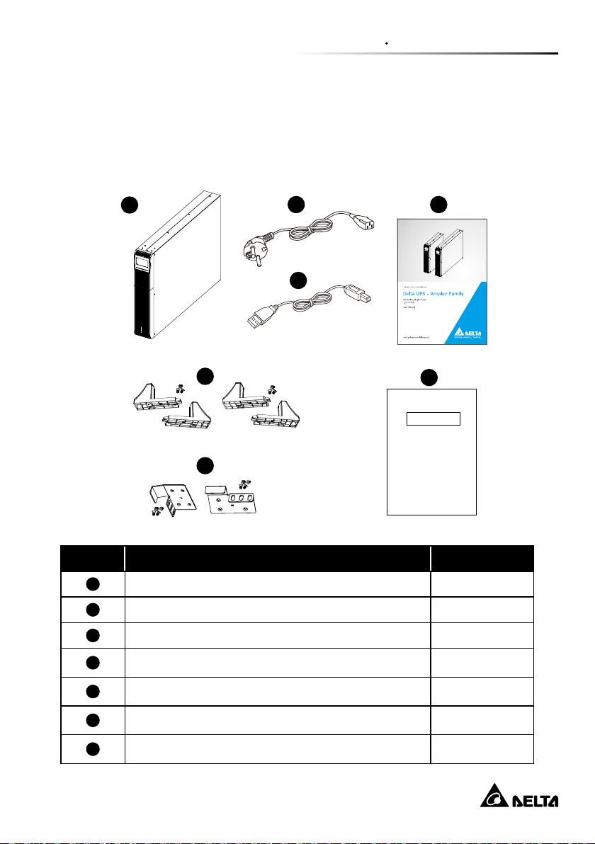
1.6 Packing List
For models UPA112M2MX0B035(1.1 kVA), UPA202M2MX0B035(2kVA),
UPA302M2MX0B035(3kVA)
1
2
4
3
5
7
Test report
6
No. Item Q’ty
1
2
UPS 1 PC
Input cable (Schuko) 1 PC
3
4
5
6
7
USB cable 1 PC
User manual 1 PC
Tower stand with screws 4 PCS
Ear kit with screws 2 PCS
Test report 1 PC
4
Page 8
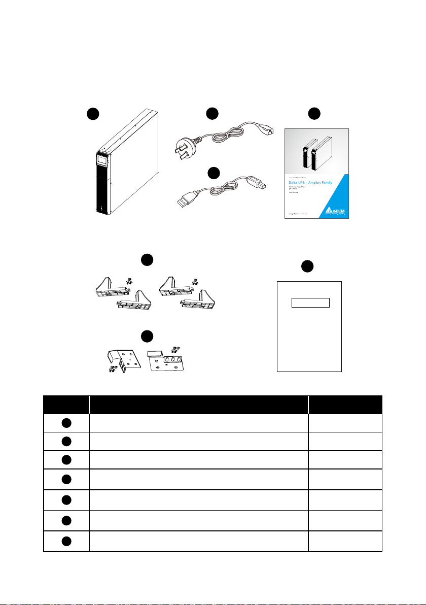
For models UPA112M2MX0B0BB(1.1 kVA), UPA202M2MX0B0BB(2kVA) ,
UPA302M2MX0B0BB(3kVA)
1
2
4
3
5
7
Test report
6
No. Item Q’ty
1
2
3
4
5
6
7
Amplon MX Series
UPS 1 PC
Input cable (AU) 1 PC
USB cable 1 PC
User manual 1 PC
Tower stand with screws 4 PCS
Ear kit with screws 2 PCS
Test report 1 PC
5
Page 9
MX-1.1K
MX-2K
MX-3K
65
65
65
8
7
4
311 10
8
7
4
3
1
2
1
2
11
9
9
8
7
4
3
1
11
2
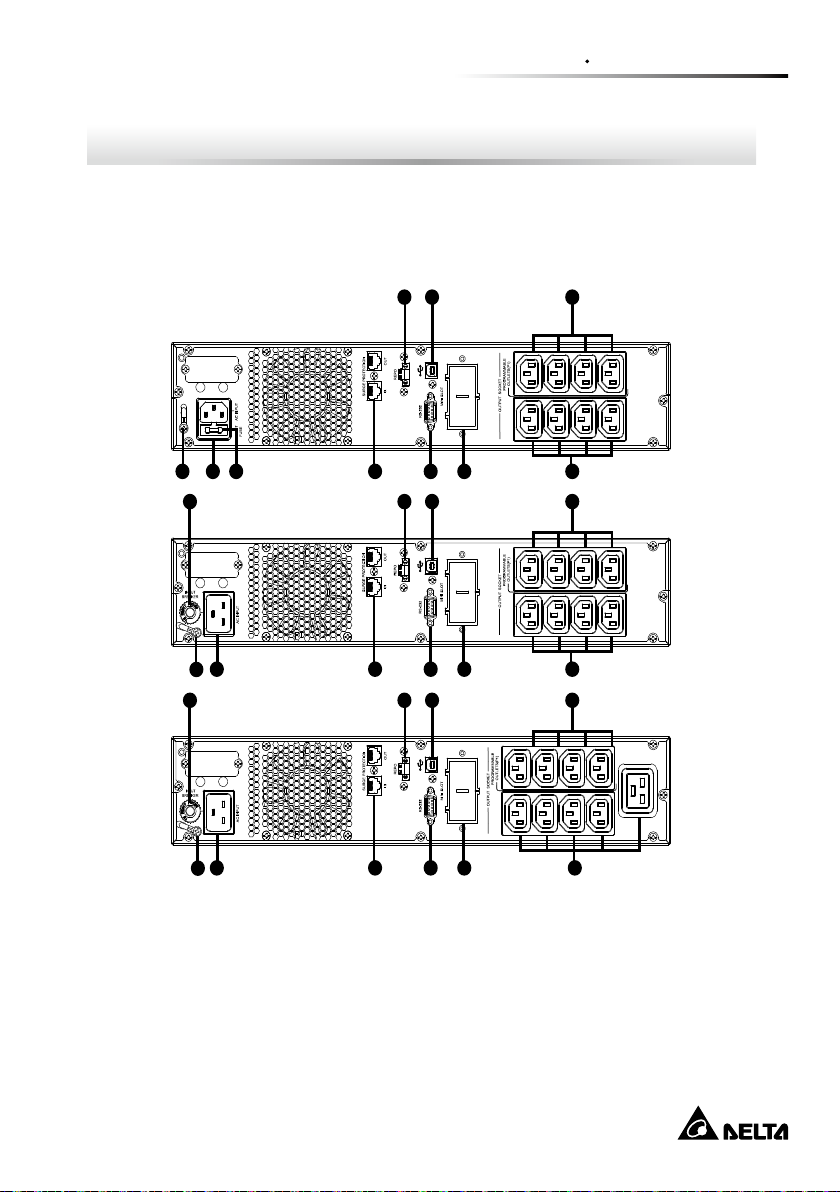
Chapter 2 : Installation and Setup
2.1 Rear Panel View
z
z
Standard Runtime Model
Chapter 2 Installation and Setup
6
Page 10

No. Item
10
11
1
2
3
4
5
6
7
8
9
Programmable outlets: connect to non-critical loads.
Output receptacles: connect to mission-critical loads.
AC input
Network/Fax/Modem surge protection
Emergency power off function connector (REPO)
USB communication port
RS-232 communication port
Mini Slot
Input circuit breaker
Fuse
Ground screw
Amplon MX Series
7
Page 11
Chapter 2 Installation and Setup
EMI/ RFI
Filters
Battery
Charger
Battery
DC- to- DC
Converter
Inverter
AVR
TX
Output
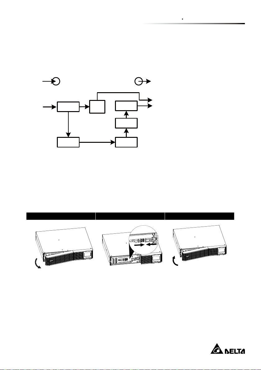
2.2 Operating principle
The operating principle of the UPS is shown as below
The UPS is composed of
mains input, EMI/RFI Filters,
Inverter, Battery charger,
DC-to-DC converter, battery,
AVR TX and UPS output
2.3 Install The UPS
For safety consideration, the UPS is shipped out from factory without connecting
battery wires. Before install the UPS, please follow below steps to re-connect bat-
tery wires rst.
Step 1 Step 2 Step 3
Remove front panel. Disconnect battery wires. Pull out the battery box
by removing two screws
8
on the front panel.
Page 12
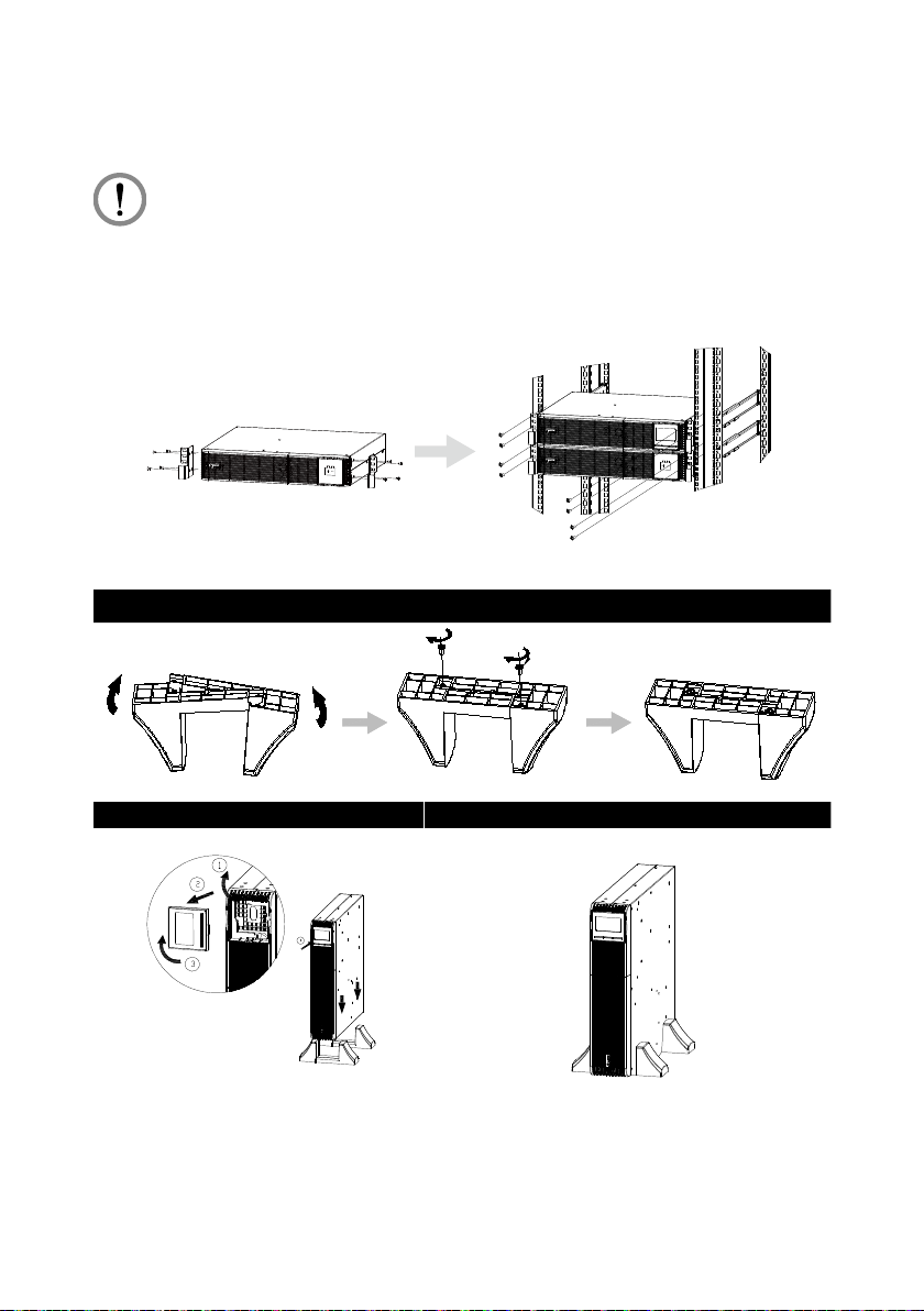
Rack-mount Installation
CAUTION :
Do NOT use the mounting brackets to lift the unit. The mounting brackets
are only for securing the unit to the rack.
Tower Installation
Step 1
Step 2 Step 3
Amplon MX Series
9
Page 13

Chapter 2 Installation and Setup
2.4 Setup the UPS
Step 1: UPS input connection
Plug the UPS into a two-pole, three-wire, grounded receptacle only. Avoid using
extension cords.
z
z
The power cord is attached to the UPS. For the type of power cord, please refer
to the table below.
UPS Type of Power Cord
1.1kVA Plug 10A Schuko or AU
2kVA Plug 16A Schuko or AU
3kVA Plug 16A Schuko or AU
Step 2: UPS output connection
There two kinds of outputs: programmable outlets and general outlets. Please
connect non-critical devices to the programmable outlets and critical devices to the
general outlets. During power failure, you may extend the backup time to critical
devices by setting shorter backup time for non-critical devices.
Step 3: Communication connection
USB port
RS-232 port
RS-232
Mini slot
MINI SLOT
10
Page 14

To allow for unattended UPS shutdown/start-up and status monitoring, connect
one end of communication cable to the USB/RS-232 port and the other to the
communication port of your PC. With the monitoring software installed, you can
schedule UPS shutdown/start-up and monitor UPS status through PC.
The UPS is equipped with mini slot perfect for either mini SNMP, mini relay I/O card
and mini modbus card. When installing either mini SNMP, mini relay I/O card or mini
modbus card in the UPS, it will provide advanced communication and monitoring
options.
Step 4: Network connection
Network/Fax/Phone surge Protection port
Connect a single modem/phone/fax line into surge-protected “IN” outlet on the back
panel of the UPS unit. Connect from “OUT” outlet to the equipment with another
modem/fax/phone line cable.
Step 5: Disable and enable REPO function
This UPS is equipped with REPO function. By default, the UPS is delivered from
factory with Pin 1 and Pin 2 closed (a metal plate is connected to Pin 1 and Pin 2)
for UPS normal operation. To activate REPO function, remove two screws on REPO
port and green connector will be removed.
NOTE :
The REPO function logic can be set up via LCD setting. Please refer to
program 7 in UPS setting for the details.
To activate REPO function,
remove these two screws.
Amplon MX Series
It’s in closed status for
UPS normal operation as default.
11
Page 15

Chapter 2 Installation and Setup
Step 6: Turn on the UPS
Press the ON/Mute button on the front panel for two seconds to power on the UPS.
NOTE :
The battery charges fully during the first five hours of normal
operation. Do not expect full battery run capability during this initial charge
period.
Step7: Install software
For optimal computer system protection, install UPS monitoring software to fully
configure UPS shutdown. Use RS-232 or USB communication cable to connect
RS-232/USB port of UPS and RS-232/USB port of PC. Then, follow steps below to
download and install monitoring software:
1. Please visit below website to download the software :
http://www.deltapowersolutions.com/en/mcis/software-center.php
UPSentry: RS232/ USB
InfraSuite Device Master: SNMP/Modbus card
2. Follow the on-screen instructions to install the software.
12
Page 16

2.5 Battery Replacement
When the icons of and
every 2 seconds, it’s time to replace batteries. Contact your service representative
to replace batteries.
Batteries can be replaced easily without turning the UPS off or disconnecting the
load. If you prefer to remove input power to change the batteries, press the OFF
button on the front panel for two seconds to power off the UPS and switch off utility
power where the UPS is connected.
are ashing in LCD display and alarm is sounding
NOTE1 :
mode.
NOTE2 :
batteries. This is normal condition and no harm for personnel. Connect the
cables quickly and rmly.
NOTE3 :
person can replace the batteries.
NOTE4 :
power outages.
DO NOT DISCONNECT the batteries while the UPS is in Battery
A small amount of arcing may occur when connecting the internal
This UPS is equipped with internal batteries and only service
Upon battery disconnection, equipment is not protected from
CAUTION!! Consider all warnings, cautions, and notes before replacing
batteries.
Amplon MX Series
13
Page 17

Chapter 2 Installation and Setup
Step 1 Step 2 Step 3
Remove front panel. Disconnect battery wires. Pull out the battery box
by removing two screws
on the front panel.
Step 4 Step 5 Step 6
Remove the top cover of
battery box and replace
the inside batteries.
Step 7
Put the front panel back
to the unit.
After replacing the batteries, put the battery
box back to original location and screw it tightly.
14
Re-connect the battery
wires.
Page 18

2.6 Battery Kit Assembly (option)
NOTE :
Please select correct battery kit procedure below to assemble it.
2-battery kit
Step 1 Step 2
Tapes
Remove adhesive tapes. Connect all battery terminals by follow-
Step 3 Step 4
Put assembled battery packs on one
side of plastic shells and insert one
more defect battery on the space.
Please assemble battery kit rst before installing it inside of UPS.
ing below chart. .
Cover the other side of plastic shell as
below chart. Then, battery kit is assembly well.
4-battery kit
Step 1 Step 2
Tapes
Tapes
Remove adhesive tapes Connect all battery terminals by follow-
ing below chart.
Amplon MX Series
15
Page 19

Step 3 Step 4
Tap e s
Tap e s
Chapter 2 Installation and Setup
Put assembled battery packs on one
side of plastic shells.
Cover the other side of plastic shell as
below chart. Then, battery kit is assembly well.
6-battery kit
Step 1 Step 2
Remove adhesive tapes. Connect all battery terminals by follow-
ing below chart.
Step 3 Step 4
Put assembled battery packs on one
side of plastic shells.
Cover the other side of plastic shell as
below chart. Then, battery kit is assembly well.
16
Page 20

Chapter 3 : Operation
3.1 Button Operation
Button Function
z
z
Turn on the UPS: Press and hold ON/Mute button for at least 2
seconds to turn on the UPS.
z
z
Mute the alarm: After the UPS is turned on in battery mode,
press and hold this button for at least 3 seconds to disable or
ON/ MUTE
Button
OFF/ ENTER
Button
enable the alarm system. But it’s not applied to the situations
when warnings or errors occur.
z
z
Up key: Press this button to display previous selection in UPS
setting mode.
z
z
Switch to UPS self-test mode: Press and hold ON/Mute button
for 3 seconds to enter UPS self-testing while in AC mode
z
z
Turn off the UPS: Press and hold this button at least 2 seconds
to turn off the UPS
z
z
Conrm selection key: Press this button to conrm selection in
UPS setting mode.
SELECT
Button
Amplon MX Series
z
z
Switch LCD message: Press this button to change the LCD
message for input voltage, input frequency, battery voltage,
battery capacity, ambient temperature, output voltage, output
frequency, load current and load percent.
z
z
Setting mode: Press and hold this button for 3 seconds to enter
UPS setting mode when UPS is off.
z
z
Down key: Press this button to display next selection in UPS
setting mode.
17
Page 21

Button Function
z
z
Exit setting mode or return to the upper menu: When working
ON/ MUTE
+ SELECT
Buttons
in setting mode, press ON/Mute and Select buttons simultaneously for 0.2 seconds to return to the upper menu. If it’s already
in top menu, press these two buttons at the same time to exit
the setting mode.
3.2 LCD Panel
Chapter 3 Operation
Display Function
Backup time information
Indicates the estimated backup time.
H: hours, M: minute, S: second.
Conguration and fault information
Indicates the conguration items, and the conguration
items are listed in details in section 3-5.
Indicates the warning and fault codes, and the codes are
listed in details in section 3-7 and 3-8.
Mute operation
Indicates that the UPS alarm is disabled.
18
Page 22

Display Function
Input, Battery, Temperature, Output & Load information
Indicate the input voltage, input frequency, battery voltage,
battery capacity, ambient temperature, output voltage,
output frequency, load current and load percentage.
k: kilo, W: watt, V: voltage, A: ampere, %: percent, ℃: centigrade degree, Hz: frequency
Load information
Indicates the load level by 0-24%, 25-49%, 50-74% and 75100%.
Indicates overload.
Programmable outlets information
Indicates that programmable management outlets are
working.
Mode operation information
Indicates the UPS connects to the mains.
Amplon MX Series
Indicates the battery is working.
Indicates the bypass circuit is working.
Indicates the inverter circuit is working.
Indicates the output is working.
Indicates the AC to DC circuit is working.
Indicates the inverter circuit is working.
Indicates the output is working.
19
Page 23

Chapter 3 Operation
Display Function
Battery information
Indicates the battery level by 0-24%, 25-49%, 50-74%, and
75-100%.
Indicates low battery.
3.3 Audible Alarm
Condition Alarm
Battery Mode Sounding every 10 seconds
Low Battery Sounding every 2 second
Overload Sounding every second
Fault Continuously sounding
3.4 LCD Display Wordings Index
Abbreviation Display Content Meaning
ENA
DIS
ESC
AO / AC
ST1/2/3
AUT / AON
/ Active Open / Close
/ / Input Waveform Sensitivity 1/2/3
/ Automatic / Always on
20
Enable
Disable
Escape
Page 24

Abbreviation Display Content Meaning
OK
ON
BL
OL
NC
OC
SF
EP
TP
CH
BF
BR
/
Over Charge
REPO
Battery Fault
Automatic / Always on
Battery Low
Over Load
Battery No Connect
Site Fault
Temperature
Charger
Battery Replacement
ON
EE
Amplon MX Series
EEPROM error
21
Page 25

3.5 UPS Setting
Parameter 1
Parameter 2
There are three parameters to set up the UPS.
There are two parameters to set up
the UPS.
Parameter 1: It’s for program alternatives. Refer to below table.
Parameter 2 is the setting options or
values for each program.
z
z
01: Output voltage setting
Chapter 3 Operation
Parameter 2: Output voltage
You could choose the following output voltage:
200: presents output voltage is 200Vac
208: presents output voltage is 208Vac
220: presents output voltage is 220Vac
230: presents output voltage is 230Vac (Default)
240: presents output voltage is 240Vac
22
Page 26

z
z
02: Programmable outlets enable/disable
Parameter 2: Enable or disable programmable outlets.
ENA: Programmable outlets enable
DIS: Programmable outlets disable (Default)
z
z
03: Programmable outlets setting
Parameter 2: Set up backup time limits for programmable outlets.
0-999: setting the backup time limits in minutes from 0-999 for
programmable outlets which connect to non-critical devices on battery
mode. (Default: 999)
Amplon MX Series
23
Page 27

Chapter 3 Operation
z
z
04: Site fault detection enable/disable
Parameter 2: Enable or disable site fault detection. You may choose the
following two options:
ENA: Site fault detection enable
DIS: Site fault detection disable(Default)
z
z
05: Autonomy limitation setting
Parameter 2: Set up backup time on battery mode for general outlets.
0-999: setting the backup time in minutes from 0-999 for general outlets on
battery mode.
DIS: Disable the autonomy limitation and the backup time will depend on
battery capacity. (Default)
Note: When setting as “0”, the backup time will be only 10 seconds.
24
Page 28

z
z
06: Battery total AH setting
Parameter 2: Set up the battery total AH of the UPS.
7-999: setting the battery total capacity from 7-999 in AH.
z
z
07: REPO logic setting
Parameter 2: Set up the REPO function control logic.
AO: Active Open (Default). When AO is selected as REPO logic, it will
activate REPO function with Pin 1 and Pin 2 in open status.
AC: Active Close. When AC is selected as REPO logic, it will activate REPO
function with Pin 1 and Pin 2 in close status.
z
z
08: Input Waveform Sensitivity setting
Amplon MX Series
25
Page 29

Chapter 3 Operation
Parameter 2: Set Input Waveform Sensitivity.
St1: Input voltage waveform detection is highly sensitive. (Default)
St2: Input voltage waveform detection is middle sensitive.
St3: Input voltage waveform detection is low sensitive. (use with generators
or Step wave input)
z
z
09: LCD display backlight setting
Parameter 2: Set up the working mode for the LCD display backlight.
Aon: LCD display backlight is on all the time.
Aut: LCD display backlight will be off after pressing the buttons 60 seconds.
UPS mode switch will wake up LCD backlight for 20 seconds. (Default)
z
z
00: Exit Setting
Exit the setting mode.
Steps for setting programmable outlet
Step 1:
Before entering setting mode, the UPS should be
in Stand-by mode (off-charging) and make sure the
battery is connected. The LCD display is shown as
right.
26
Page 30

Step 2:
Press and hold the “Selection” button for 3 seconds
to enter Setting mode.
Step 3:
Press the “Up” button (ON/MUTE) to switch to “02”
of program list. Then press “Enter” button to enter
value setting of parameter 2. Press the “Up” button
to change the value to “ENA” to enable the programmable outlet function. Then press “Enter” but-
ton again to conrm the setting.
Step 4:
Press the “Up” button (ON/MUTE) again to switch
to “03” of program list. Then press “Enter” button for
setting programmable outlet time. Push “Up” button
to change the value of backup time according your
demand. Then press “Enter” to conrm the setting.
Step 5:
Press “Up” button (ON/MUTE) to switch to “00” of
program list. Then press “Enter” button to exit setting menu.
Step 6:
Disconnect AC input and wait until the LCD display is off. The new setting will
be activated when turning on the UPS again.
3.6 Operating Mode Description
z
z
Normal mode
When the input voltage is within
voltage regulated range, UPS will
power the output directly from the
mains. In this mode, when battery
is fully charged, the fan will stop
working for energy saving.
Amplon MX Series
27
Page 31

z
z
Buck mode when AC is normal.
When the input voltage is higher
than the voltage regulation range
but lower than high loss point, the
buck AVR will be activated.
z
z
Boost mode when AC is normal.
When the input voltage is lower
than the voltage regulation range
but higher than low loss point, the
boost AVR will be activated.
z
z
Battery Mode
When the input voltage is beyond the acceptable range
or power failure and alarm is
sounding every 10 seconds,
UPS will backup power from
battery.
Chapter 3 Operation
z
z
Standby mode
UPS is powered off and no output supply power, but still can
charge batteries.
z
z
Fault mode
The UPS is powered off and
there is no output, but the batteries can still be charged.
28
Page 32

3.7 Faults Reference Code
Fault Event Fault Code Icon
Bus start fail 01 x
Bus over 02 x
Bus under 03 x
Inverter soft start failure 11 x
Inverter voltage high 12 x
Inverter voltage Low 13 x
Inverter output short 14 x
Battery voltage too high 27 x
Battery voltage too low 28 x
Over temperature 41 x
Overload 43
Charger failure 45 x
3.8 Warning Indicator
Warning Icon (ashing) Code Alarm
Low battery
Overload
Battery is not
connected
Over charge
Site wiring fault
Amplon MX Series
Sounding every 2 seconds
Sounding every second
Sounding every 2 seconds
Sounding every 2 seconds
Sounding every 2 seconds
29
Page 33

Chapter 3 Operation
Warning Icon (ashing) Code Alarm
REPO enable
Over
temperature
Charger failure
Battery fault
Battery
replacement
EEPROM error
Sounding every 2 seconds
Sounding every 2 seconds
Sounding every 2 seconds
Sounding every 2 seconds
(At this time, UPS is off to
remind users something wrong
with battery)
Sounding every 2 seconds
NOTE: “Site Wiring Fault” function can be enabled/disabled via software. Please
check software manual for the details.
30
Page 34

Chapter 4 : Troubleshooting
If the UPS system does not operate correctly, please solve the problem by using the
table below.
Symptom Possible Cause Remedy
No indication and alarm
even though the mains
is normal.
The icon
warning code
ing on LCD display and
alarm is sounding every
2 seconds.
The icon
the warning code
ashing on LCD display
and alarm is sounding
every 2 seconds.
The icon
the warning code
ashing on LCD display
and alarm is sounding
every 2 seconds.
Fault code is shown as
27 on LCD display and
alarm is continuously
sounding.
and the
ash-
, and
, and
The AC input power is not
connected well.
The AC input is connected
to the UPS output.
REPO function is activated. Set the circuit in close
Line and neutral conductors
of UPS input are reversed.
The external or internal
battery is incorrectly connected.
Battery voltage is too high
or the charger is fault.
Check if the input
power cord rmly connected to the mains.
Plug AC input power
cord to AC input correctly.
position to disable
REPO function.
Rotate mains power
socket by 180° and
then connect to UPS
system.
Check if all batteries
are connected well.
Contact your dealer.
Fault code is shown as
28 on LCD display and
alarm is continuously
sounding.
Amplon MX Series
Battery voltage is too low or
the charger is fault.
31
Contact your dealer.
Page 35

Chapter 4 Troubleshooting
Symptom Possible Cause Remedy
The icon
, and
the warning code
ashing on LCD display
and alarm is sounding
every second.
Fault code is shown as
43 and the icon
is
lighting on LCD display.
Alarm is continuously
sounding.
Fault code is shown as
14 and alarm is continuously sounding.
Fault code is shown as
01, 02, 03, 11, 12, 13
and 41 on LCD display
and alarm is continuously sounding.
Battery backup time is
shorter than nominal
value
UPS is overload Remove excess loads
from UPS output.
The UPS shut down automatically because of overload at the UPS output.
The UPS shut down
automatically because
short circuit occurs on the
UPS output.
A UPS internal fault has
Remove excess loads
from UPS output and
restart it.
Check output wiring and if connected
devices are in short
circuit status.
Contact your dealer
occurred.
Batteries are not fully
charged
Charge the batteries
for at least 5 hours
and then check capacity. If the problem still
persists, consult your
dealer.
Fault code is shown as
45 on LCD display. At
the same time, alarm is
continuously sounding.
Batteries defect Contact your dealer to
replace the battery.
The charger does not have
Contact your dealer.
output and battery voltage
is less than 10V/PC.
32
Page 36

Chapter 5 : Storage and Maintenance
z
z
Operation
The UPS system contains no user-serviceable parts. If the battery service life
(3~5 years at 25°C ambient temperature) has been exceeded, the batteries
must be replaced. In this case, please contact your dealer.
Be sure to deliver the spent battery to a recycling facility or ship
it to your dealer in the replacement battery packing material.
z
z
Storage
Before storing, charge the UPS 5 hours. Store the UPS covered and upright in
a cool, dry location. During storage, recharge the battery in accordance with the
following table:
Storage Temperature Recharge Frequency Charging Duration
-25°C ~ 40°C Every 3 months 1 ~ 2 hours
40°C ~ 45°C Every 2 months 1 ~ 2 hours
Amplon MX Series
33
Page 37

Chapter 6 Technical Specications
Chapter 6 : Technical Specications
Model MX-1.1K MX-2K MX-3K
Capacity
Voltage Range
Frequency Range 50/60 Hz (auto sensing)
Connection IEC C14 IEC C20
Phase Single phase with ground
Nominal voltage 200V / 208V / 220V / 230V / 240V
Voltage Regulation ±1.5% (Batt. Mode)
Frequency Range
(Batt. Mode)
Connection IEC C13 (4+4)
Overload
1100VA / 990W 2000 VA / 1800 W 3000VA / 2700W
Input
200V: 150-234V / 208V: 156-243V / 220V: 162-268V
/ 230V: 170-280V / 240V: 177-290V
Output
50 Hz or 60 Hz ± 1 Hz
IEC C13 (4+4)
IEC C19 (1)
103% ~ 120%: 5 minutes (1 minutes @battery mode),
120% ~ 150%: 10 seconds,
>150%: UPS shutdown immediately
Current Crest Ratio 3:1
Harmonic Distortion ≤ 2%(linear load), ≤ 5% (non-linear load)
Waveform
(Batt. Mode)
Efciency
Normal Mode 98% 98.5%
Buck & Boost Mode 95.5% 96.5%
Pure Sinewave
34
Page 38

Model MX-1.1K MX-2K MX-3K
Battery
Battery Type
Sealed lead-acid battery
12V/9Ah
Numbers 2 4 6
Recharge Time 4 hours recover to 90% capacity
Physical
Dimension
(W x D x H)(mm)
438 x 410x 88 438 x 510 x 88 438 x 630 x 88
Net Weight (kg) 14.1 21.3 32.1
Environment
Operation
Temperature
0- 40°C
Relative Humidity 20-90 % RH (non-condensing)
Noise Level < 45 dBA
< 45 dBA @ Normal Mode,
< 55 dBA @ Battery mode
Communication
Interface
RS-232 Port x 1, USB Port x 1, MINI Slot x 1,
Surge Protection, REPO
NOTE :
1. *Derate to 85% of capacity when the output voltage is adjusted to 200/208VAC.
2. Product specications are subject to change without further notice.
Amplon MX Series
35
Page 39

Chapter 7 Warranty
Chapter 7 : Warranty
Seller warrants this product, if used in accordance with all applicable instructions,
to be free from original defects in material and workmanship within the warranty
period. If the product has any failure problem within the warranty period, Seller will
repair or replace the product at its sole discretion according to the failure situation.
This warranty does not apply to normal wear or to damage resulting from improper
installation, operation, usage, maintenance or irresistible force (i.e. war, fire,
natural disaster, etc.), and this warranty also expressly excludes all incidental and
consequential damages.
Maintenance service for a fee is provided for any damage out of the warranty
period. If any maintenance is required, please directly contact the supplier or Seller.
WARNING:
The individual user should take care to determine prior to use whether the
environment and the load characteristic are suitable, adequate or safe for
the installation and the usage of this product. The User Manual must be
carefully followed. Seller makes no representation or warranty as to the
suitability or tness of this product for any specic application.
36
Page 40

Version Date : 2019_06_19
 Loading...