

Page 1
The power behind competitiveness
Delta UPS - Amplon Family
RT Series, Three Phase
10/ 15/ 20 kVA
Maintenance Bypass Box
for Single UPS
User Manual
www.deltapowersolutions.com
Page 2

Save This Manual
This manual contains important instructions and warnings that you should follow during the
installation, operation, storage and maintenance of this product. Failure to heed these
instructions and warnings will void the warranty.
Copyright © 2019 by Delta Electronics Inc. All Rights Reserved. All rights of this User Manual
(“Manual”), including but not limited to the contents, information, and figures are solely owned and
reserved by Delta Electronics Inc.(“Delta”). The Manual can only be applied to the operation or the
use of this product. Any disposition, duplication, dissemination, reproduction, modification,
translation, extraction, or usage of this Manual in whole or in part is prohibited without the prior
written permission of Delta. Given that Delta will continuously improve and develop the product,
changes may be made to the information in this Manual at any time without obligation to notify any
person of such revision or changes. Delta will make all possible efforts to secure the accuracy and
the integrity of this Manual. Delta disclaims any kinds or forms of warranty, guarantee, or
undertaking, either expressly or implicitly, including but not limited to the completeness,
faultlessness, accuracy, non-infringement, merchantability or fitness for a particular purpose of the
manual.
AmplonRTSeries
1
Page 3

Table of Contents
1. Product Introduction ................................................................................. 3
2. Important Safety Instructions ................................................................... 4
2.1. Safety Instructions .......................................................................... 4
2.2. Standard Compliance ..................................................................... 5
2.3. Storage ............................................................................................. 5
3. Package list ................................................................................................ 6
4. The Rear Panel ........................................................................................... 8
5. Installation Procedures ........................................................................... 11
6. Connection ............................................................................................... 14
6.1. Pre-connection Warnings ............................................................. 14
6.2. The Connection with the UPS model without power cables ..... 14
6.3. Main input , Bypass Input and Output Connection of the MBB 18
6.3.1. Single Source Input & Single Phase Output .................... 24
6.3.2. Dual Source Input & Single Phase Output ....................... 25
6.3.3. Dual Source Input & Three Phase Output ........................ 26
6.3.4. Single Source Input & Three Phase Output ..................... 27
6.4. Connection of the MBB and the UPS .......................................... 28
7. Operation Procedures ............................................................................. 31
8. Maintenance Bypass ............................................................................... 32
Appendix 1 : Technical Specifications .......................................................... 35
Appendix 2 : Warranty .................................................................................... 37
2
Page 4

Chapter 1 : Product Introduction
The Delta Maintenance Bypass Box (MBB) is applicable to Delta Amplon UPSs:
RT-15K3P and RT-20K3P. The MBB provides AC input power to the UPS and
connects the output of the UPS to the critical loads and is configurable for single-
phase or three-phase output to suit your needs. When your UPS needs
maintenance, you can switch on the MBB’s manual bypass switch to let the
power be transferred from the inverter output to the manual bypass output to
ensure continuous power supply to your critical loads when the UPS is under
maintenance. Product Introduction
AmplonRTSeries
3
Page 5

Chapter 2 : Important Safety Instructions
Important Safety Instructions
2.1. Safety Instructions
Installation Warnings
• Before installation and usage, please read this User Manual thoroughly.
This will help you to use the product correctly and safely.
• Install the MBB in a well-ventilated area, away from excess moisture, heat,
dust, flammable gas or explosives.
• To avoid fire accidents and electric shock, please install the MBB in an
indoor area free of conductive contaminants and the temperature and
humidity must be well-controlled. For the temperature and humidity
specifications, please refer to Appendix 1 : Technical Specifications.
• Leave adequate space (at least 50 cm) around all sides of the MBB for
proper ventilation.
Connection Warnings
• The MBB must be well grounded due to a possible risk of current leakage.
• The installation of upstream and downstream protective devices is highly
recommended when the MBB is connected to the UPS.
• The protective devices connected to the MBB must be installed near the
MBB and must be easily accessible for operation.
•
If you need to move the MBB or perform re-wiring, please turn off the AC
input power. Otherwise, the output end might still be energized, which might
cause electric shock.
Usage Warnings
• To ensure reliable operation of the MBB and to protect the MBB from
overheating, the slits and openings in the MBB must not be blocked or
covered.
• Before usage, you must allow the MBB to adjust to room temperature for at
4
Page 6

least one hour to avoid moisture condensing inside the MBB.
• Do not pour and splash any liquid on the MBB. Do not insert any object into
the MBB’s slits and openings. Do not put beverage containers on or around
the MBB.
• Do not apply any cleaning liquid or cleaning spray to the MBB. Before
cleaning, please make sure that the input power cables have been
unplugged.
• All maintenance services must be performed by qualified service personnel.
• Forbid opening or removing the cover of the MBB by yourself to avoid high
voltage electric shock.
• You must contact qualified service personnel if either of the following events
occurs:
1. Liquid is poured or splashed on the MBB.
2. The MBB does not run normally after the instructions in this User Manual
are carefully observed.
2.2. Standard Compliance
IEC/EN 62040-1
2.3. Storage
• Prior to installation
If the MBB needs to be stored prior to installation, it should be placed in a
dry area. The allowable storage temperature and relative humidity (non-
condensing) are -15°C ~ +55°C and 5 ~ 95% respectively.
• After usage
Remove all equipment from the MBB, and store the MBB in a dry and well-
ventilated area at a temperature between -15°C and +55°C and at a relative
humidity (non-condensing) between 5 ~ 95%.
5
AmplonRTSeries
Page 7
Chapter 3 : Package List
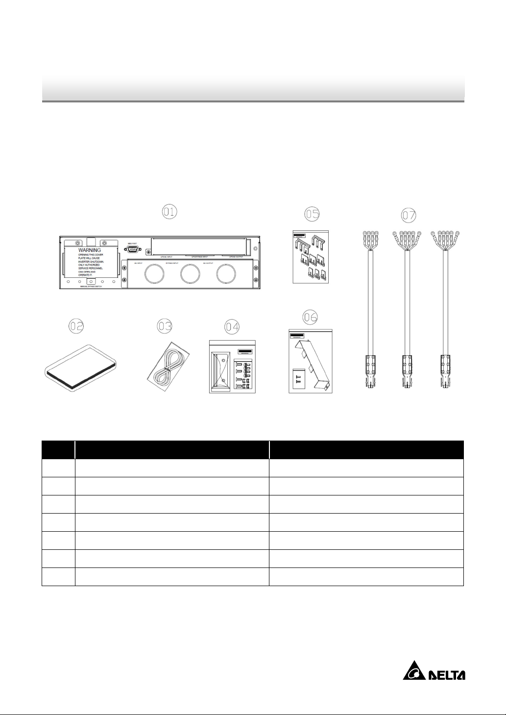
3. Package list
The package contains the following items shown in Figure 3-1. Please check if
any item is missing. If there is anything missing, please contact the dealer
immediately.
Model: MBB-RT-15/20K WW2U
(Figure 3-1: Package List)
No. Item Quantity
MBB 1 PC
1
User Manual 1 PC
2
MBB Communication Cable 1 PC
3
Ear Bracket Kit 1 SET
4
BUS Bar 1 SET
5
6 Cover and Screws*1
7 Power cable*
2
1 SET
1 SET
6
Page 8

NOTE :
1
1. *
The cover and screws should be installed on the MBB to protect the
power cables as shown in Figure 6-12.
2. *2 There are 3 power cables: main input power cable (4 pins), bypass
input power cable (6 pins) and output power cable (6 pins). These three
power cables are for connection with the UPS model shipped without the
cables already being installed on the UPS; the connection should be
performed by qualified service personnel.
3. If there is any damage or anything missing, please immediately contact
the dealer from whom you purchased the unit.
4. If the MBB needs to be returned, carefully repack the MBB and all of
the accessories with the original packing material that came with the unit.
AmplonRTSeries
7
Page 9
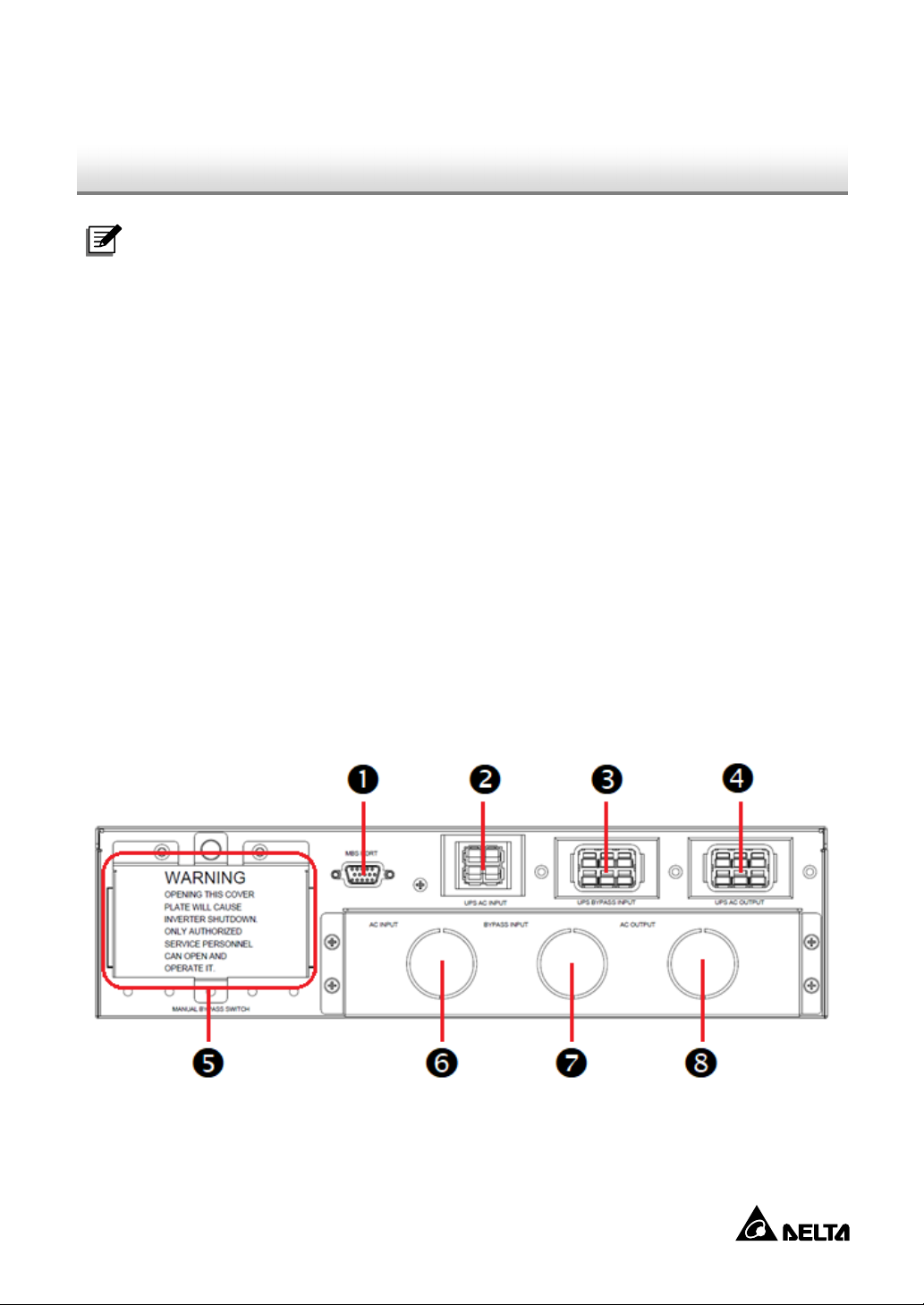
4. The Rear Panel
NOTE:
1. There are no operational components or interfaces on the front of the
MBB.
2. The UPS AC input, the UPS bypass input and the UPS AC output
marked with ❷ ❸ ❹ in Figure 4-1 are originally covered, after removing
the cover, you can see them and conduct the connection. For the details
of connection, please refer to Chapter 6: Connection. Please note that
the cover should be reinstalled as the original state after you remove the
connection between the MBB and the UPS.
3. The AC input, the bypass input and the AC output marked with ❻ ❼
❽ in Figure 4-1 are covered with a knockout cover respectively. When
conducting the connection, you have to remove the knockout covers
shown in Figure 6-1. For the details of connection, please refer to Chapter
6: Connection. Please note that the knockout covers do not need to be
Chapter 4 : The Rear Panel
reinstalled.
(Figure 4-1: The Rear Panel of the MBB)
8
Page 10
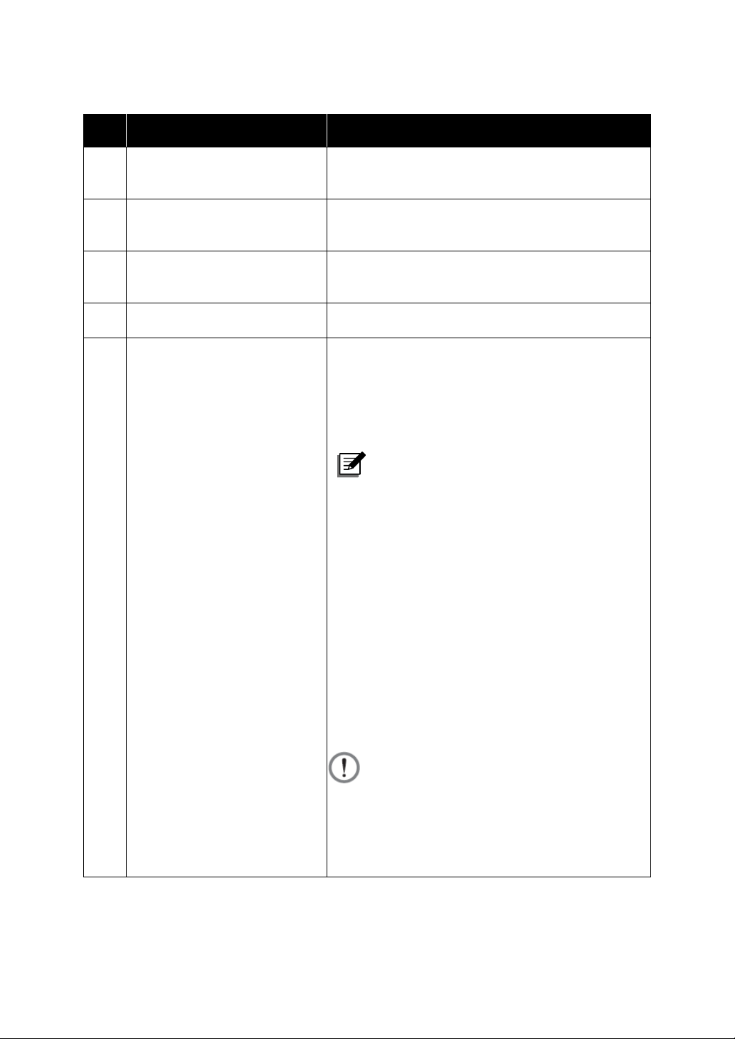
No. Item Function
1 MBS Port
Connect to the parallel port of UPS to
send messages.
Connect to the UPS’s AC input power
2 UPS AC Input Port
cable.
Connect with the UPS’s bypass power
3 UPS Bypass Input Port
cable.
4 UPS AC Output Port Connect with the UPS’s output socket.
No connection is needed. The function is
to switch the UPS into manual bypass
mode for maintenance without power
supply interruption.
NOTE:
There is a warning cover on the
manual bypass switch. After you
unscrew the 3 screws shown in
Manual Bypass Switch
5
(covered)
AmplonRTSeries
Figure 8-1 and remove the
warning cover, you can see the
switch and the MBB’s detector will
be automatically activated and
send a message to the UPS to
make it transfer to bypass mode.
WARNING:
Opening the warning cover will
cause inverter shutdown. Only
authorized service personnel can
open and operate it.
9
Page 11

6 AC Input Terminals
7 Bypass Input Terminals
Include mL1 (VIN_R) / mL2 (VIN_S) / mL3
(VIN_T) / N (IP_N) *
1
terminals which connect
to the main AC source.
Include bL1 (BYP_R) / bL2 (BYP_S) / bL3
(BYP_T )/ N (IP_N) *
1
terminals which
connect to the bypass source.
Include L1 (VOUT_R) / L2 (VOUT_S) / L3
8 AC Output Terminals
NOTE:
*1
For dual-source input configurations, the main AC source and the
bypass source must use the same neutral (N). For the details of
connection, please refer to Chapter 6: Connection.
(VOUT_T) / N (OP_N) which connect to the
critical loads.
10
Page 12
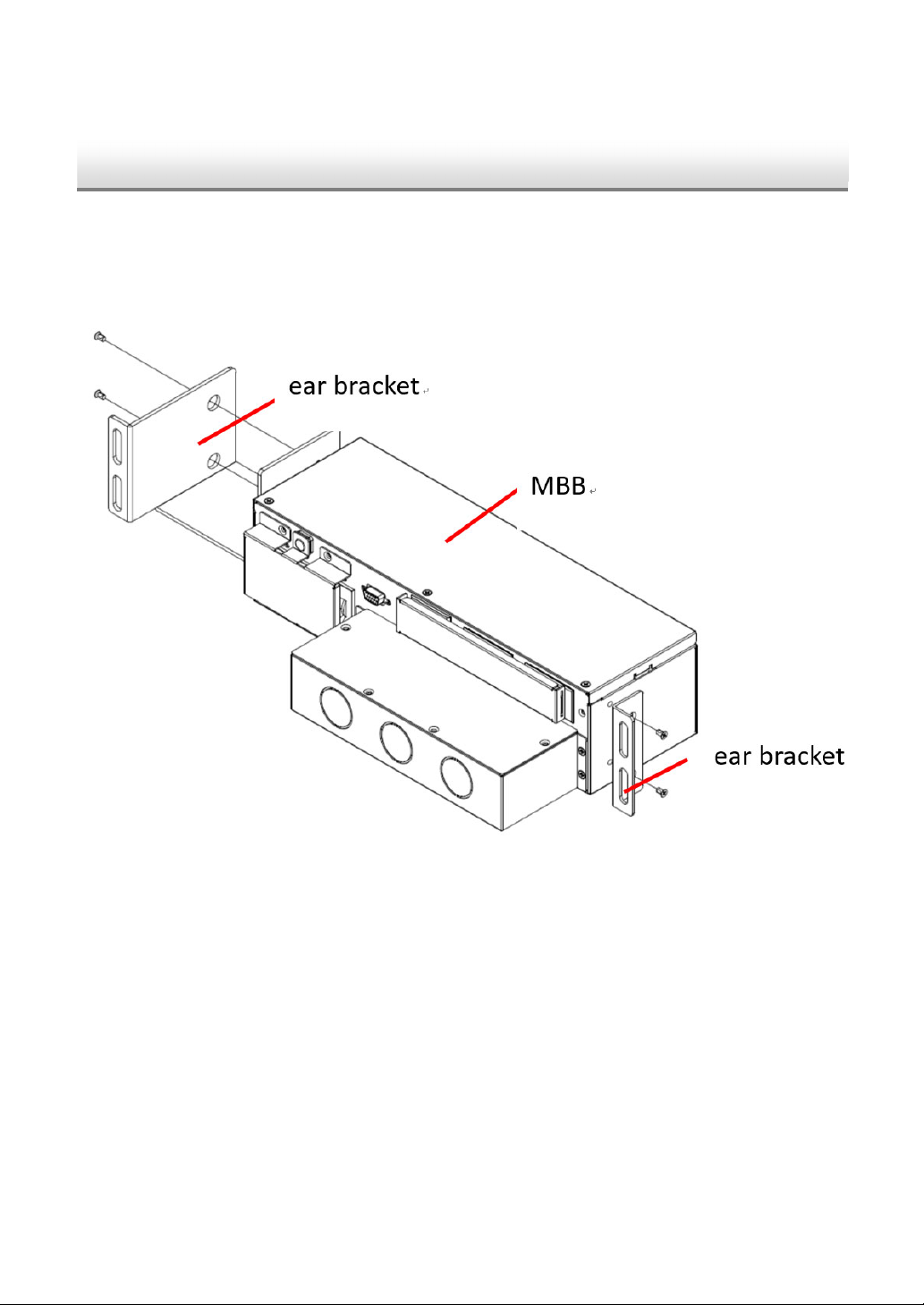
Chapter 5 : Installation Procedures
5. Installation Procedures
Please follow the steps below to conduct rack mounting:
Step ❶ : Attach the included ear brackets to the MBB and verify all screws have
been properly fastened. Please see Figure 4-1.
(Figure 5-1: Attach the Included Ear Brackets to the MBB)
11
AmplonRTSeries
Page 13

Step ❷ : Install the MBB on standard 19-inch server rack and tighten the screws
provided in the kit. See Figure 5-2.
(Figure 5-2: Install the MBB to Standard 19-inch Server Rack)
NOTE :
1. If the MBB is installed behind the Delta lithium-ion battery pack
(optional), please keep MBB away from the Delta lithium-ion battery
pack at least 1cm.
2. When MBB is connected to UPS, the MBB should be installed on the
12
Page 14

UPS or under the UPS depend on installation environment. For
example, the MBB is installed under the UPS, see Figure 5-3.
AmplonRTSeries
(Figure 5-3: Install the MBB under UPS)
13
Page 15

Chapter 6 : Connection
6. Connection
To connect the UPS with the AC source, bypass source and critical loads via the
MBB, the user should connect the UPS with the MBB first; then, connect the
MBB with the AC source, bypass source and critical loads.
NOTE:
1. User can decide whether to adopt single power source or dual power
source and single phase or three phase, which would influence the ways
of wiring configuration. For more details, please refer to Chapter 6.3.1 ~
Chapter 6.3.4.
2. Regarding the connection between the UPS and the battery pack,
please refer to Delta Amplon RT Series 15/ 20kVA UPS User Manual and
the Delta battery pack User Manual.
6.1. Pre-connection Warnings
The circuit breaker or other protective device must be installed at the AC power
input. Please follow Delta Amplon RT Series 15/ 20kVA UPS User Manual to
install the input protective device.
6.2. UPS Model Without Power Cables
MBB should be connected to the UPS with the power cables. If the UPS model
user originally purchased does not have the power cables installed before
shipment, the user should use the three power cables provided in the MBB’s
package to complete the connection with the UPS. The power cables to be
connected include the main input, bypass input and output cables. Please follow
the steps below to perform the power cable connection with the UPS; the
connection should be performed by qualified service personnel.
14
Page 16

1. There are an upper cover at the rear of the UPS and three knockout covers on
UPS’s rear panel, remove them as shown in Figure 6-1. After removing them,
you can see the UPS wiring terminals from the top.
(Figure 6-1: Remove the Upper Cover at the Rear of the UPS and the Three
Knockout Covers from the UPS’s Rear Panel)
2. Please follow step ❶ to step ❸ below to connect the three power cables to the
UPS wiring terminals (the AC input terminals, the bypass input terminals, the UPS
output terminals and the grounding terminal). Use three cable glands (user-
supplied) to firmly fix the cables on the UPS.
Step ❶ : Fix the AC input power cable (4 pins) on AC input terminals of UPS.
Please note that the 4 pins of the main input power cable should be connected to
the right position of terminals (mL1, mL2, mL3 and N) as shown in Figure 6-2.
15
AmplonRTSeries
Page 17

(Figure 6-2: The Connection of Main Input Power Cable with AC Input
Terminals of UPS)
Step ❷ : Fix the bypass input power cable (6 pins) on the bypass input terminals
and grounding terminal of the UPS. Please note that the 6 pins of the bypass input
power cable should be connected to the right position of the terminals (bL1, bL2,
bL3, N and grounding) as shown in Figure 6-3.
16
Page 18

(Figure 6-3: The Connection of the Bypass Input Power Cable with Bypass
Input Terminals and Grounding Terminal of UPS)
AmplonRTSeries
17
Page 19

Step ❸ : Fix the included output power cable (6 pins) on the output terminals and
grounding terminal of the UPS. Please note that the 6 pins of the output power
cable should be connected to the right position of the terminals (L1, L2, L3, N, N
and grounding) as shown in Figure 6-4.
(Figure 6-4: the Connection of the Output Power Cable on the Output
Terminals of the UPS and the Grounding Terminal.)
6.3. Main Input, Bypass Input and Output Connection of the MBB
WARNING:
The cables to be connected include the main input cable, the bypass input
cable and the output cable. When choosing the cables, please follow the
local wiring regulations and take into account the environmental conditions.
18
Page 20

Regarding the nominal current of the MBB with different phase configurations
(single-phase or three-phase), please refer to Table 6-1.
Table 6-1: MBB Nominal Current
Wiring
configuration
(Input Phase:
Bypass Phase:
Output Phase)
(3:3:3)
(3:1:1)
NOTE:
1. A maximum voltage drop of 4Vac on each cable core is allowed.
Nominal Input Phase
Current*1 (A)
Rated Input Voltage Rated Output Voltage
220/380V 230/400V 240/415V 220/380V 230/400V 240/415V
Main:
35A (3P)
Bypass:
30.6A (3P)
Main:
35A (3P)
Bypass:
91.8A (1P)
Main:
34.1A (3P)
Bypass:
29.3A (3P)
Main:
34.1A (3P)
Bypass:
87.9A (1P)
Main:
32.3A (3P)
Bypass:
28.1A (3P)
Main:
32.3A (3P)
Bypass:
84.3A (1P)
Nominal Output Phase Current*2
(A)
30.3A (3P) 29A (3P) 27.8A (3P)
90.9A (1P) 87A (1P) 83.4A (1P)
2. To avoid electromagnetic interference, do not loop the cable.
3. *1 Applicable to both main input and bypass input.
4. *2 The use of non-linear loads influences the selection of the output and
bypass neutral cables. The neutral cable current may exceed the rated
phase current and can be up to 1.732 times higher than the rated phase
current. In such a condition, you have to use a cable with wider wire
diameter.
AmplonRTSeries
19
Page 21

Table 6-2 lists the minimum cross-sectional area of the cable recommended to the
user. You can select the appropriate cables according to Table 6-1 and Table 6-2.
Table 6-2: Recommended Cable Size (Environment Temperature: 25°C)
Model
(Input P:
Bypass P:
Output P)
(3:3:3)
(3:1:1)
Input Output Bypass
mm2 AWG mm2 AWG mm2 AWG mm2 AWG mm2 AWG
6 8 6 8 6 8 6 8 16 4
6 8
6
× 3PCS 8 × 3PCS 6 × 3PCS 8 × 3PCS 6 × 3PCS 8 × 3PCS
Neutral
Ground
Line
35 1
NOTE:
Only qualified personnel can perform installation, wiring, operation and
maintenance. Prior to supplying any power to the UPS, make sure the
MBB has been suitably grounded.
External Protection Device
You must install a circuit breaker (or other protection device) between the main AC
source and the MBB; if you adopt dual-input configurations, you must also install
a circuit breaker (or other protection device) between the bypass source and the
MBB. Select the appropriate cables according to Table 6-3.
20
Page 22

Table 6-3: Protection Device Capacity
Model
(Input P: Bypass P:
With RT-15K3P With RT-20K3P
Output P)
50A/ Type D (main)
63A/ Type D (main)
(3:3:3)
50A/ Type D (bypass)
50A/ Type D (main)
63A/ Type D (bypass)
63A/ Type D (main)
(3:1:1)
100A/ Type D (bypass)
125A/ Type D (bypass)
The section provides general guidance for qualified installation engineers. A
qualified installation engineer should be aware of local wiring regulations and other
relevant knowledge.
NOTE:
1. For dual-source input configurations, the main AC source and the
bypass source must use the same neutral (N).
2. The three-phase UPS must be equipped with four-pole protection
devices to cut off the power from four cables, and the single-phase UPS
must be equipped with two-pole protection devices to cut off the power
from 2 cables.
AmplonRTSeries
21
Page 23

The power cable connection of the MBB needs to be connected through the
input and output terminals at the rear of the MBB, as shown in Figure 6-5.
(Figure 6-5: The Input and Output Terminals of the Rear Panel of the MBB)
The wiring terminals include:
No. Item Description Function
Include mL1 (VIN_R) / mL2
1
AC Input
(VIN_S) / mL3 (VIN_T) / N (IP_N) *
Terminals
Connect to the main AC
1
source.
terminals.
Include bL1 (BYP_R) / bL2
Bypass Input
2
Terminals
(BYP_S) / bL3 (BYP_T) / N (IP_N) *
Connect to the bypass
1
AC source.
terminals.
Include L1 (VOUT_R) / L2
3
Ac Output
(VOUT_S) / L3 (VOUT_T) / N (OP_N)
Terminals
Connect to the critical
loads.
terminals.
22
Page 24

1. For UPS protective
earthing: connects to the
main AC source and
bypass source*2.
2. For bonding: connects
Includes one grounding
to the critical loads.
4
terminal.
3. When performing
grounding, please refer
to the steps below. For
the protective earthing.
Please refer to Figure 6-
6 for the connection
method.
NOTE:
*1 For dual-source input configurations, the main AC source and the
bypass source must use the same neutral (N).
*2 For the UPS with dual-source input configuration only.
Regarding the connection of grounding terminal, please follow the steps below
and connect the cables with grounding terminals in sequence as stated below
and shown in Figure 6-6.
Step ❶ :
Connect the cable with protective earthing terminal ( ❶ ) , and fix the cable with
the lock washer ( ❷ ) and nut ( ❸ ).
Step ❷ :
Connect another cable with protective bonding terminal ( ❹ ), and fix the cable
with the lock washer ( ❺ ) and nut ( ❻ ).
23
AmplonRTSeries
Page 25

(Figure 6-6: the Cable Connection with Protective Earthing Terminal and
Protective Bonding Terminal )
The MBB input can be set as single-source input or dual-source input and the
MBB output can be set as three-phase or single-phase, which depends on the
way you install the bus bars (provided in the package) and the output phase
setting. There are four kinds of configurations for your choice. See Chapter 6.3.1
~ Chapter 6.3.4 below (the MBB wiring terminals are marked in block font).
6.3.1. Single Source Input & Single Phase Output
1. Install the bus bars by following Figure 6-7.
2. Connect to AC source (L1/ L2/ L3/ N): connect L1 to mL1, bL1, bL2, or bL3; L2
to mL2; L3 to mL3; N to the N terminals.
3. Connect to the loads (L/ N): connect the load’s L to L1, L2, or L3 and N to the
N terminals.
24
Page 26

(Figure 6-7: MBB Bus Bar Installation for Single Source Input & Single
Phase Output Configuration)
6.3.2. Dual Source Input & Single Phase Output
1. Install the bus bars by following Figure 6-8.
2. Connect to AC source (L1/ L2/ L3/ N): connect L1 to mL1; L2 to mL2; L3 to mL3;
N*1 to one of the N terminals.
3. Connect to bypass source (L/ N): connect L to bL1, bL2, or bL3 ; N*1 to two of
the N terminals.
4. Connection to the loads (L/ N): connect the load’s L to L1, L2, or L3 and the
load’s N to one of the N terminals.
NOTE:
*1 For dual-source input configurations, the main AC source and the
bypass source must use the same neutral (N).
AmplonRTSeries
25
Page 27

(Figure 6-8: MBB Bus Bar Installation for Dual Source Input & Single Phase
Configuration)
6.3.3. Dual Source Input & Three Phase Output
1. Install the bus bars following Figure 6-9.
2. Connect to AC source (L1/ L2/ L3/ N): connect L1 to mL1; L2 to mL2; L3 to mL3;
N*1 to one of the N terminals.
3. Connect to bypass source (L1/ L2/ L3/ N): connect L1 to bL1; L2 to bL2; L3 to
bL3.
4. Connect to the loads (L1/ L2/ L3/ N): connect the loads’ L1/ L2/ L3 to L1/ L2/ L3
respectively and the loads’ N to one of the N terminals.
NOTE:
*1 For dual-source input configurations, the main AC source and the
bypass source must use the same neutral (N).
26
Page 28

(Figure 6-9: MBB Bus Bar Installation for Dual Source Input & Three Phase
Output Configuration)
6.3.4. Single Source Input & Three Phase Output
1. Install the bus bars by following Figure 6-10.
2. Connection to AC source (L1/ L2/ L3/ N): connect L1 to mL1or bL1; L2 to mL2
or bL2; L3 to mL3 or bL3; N to one of the UPS’s N terminals.
3. Connection to the loads (L1/ L2/ L3/ N): connect the load’s L1/ L2/ L3 to L1/ L2/
L3 respectively and the load’s N to one of the N terminals.
AmplonRTSeries
27
Page 29

(Figure 6-10: MBB Bus Bar Installation for Single Source Input & Three
Phase Output Configuration)
6.4. Connection of the MBB and the UPS
Insert three power cables of UPS to the ports on MBB’s rear panel. Please see
steps ❶ ❷ ❸ in Figure 6-11.
Install the two ends of the provided MBB communication cable on the MBB’s
MBS port and the UPS’s parallel port. Please see step ❹ in Figure 6-11.
28
Page 30

(Figure 6-11: Installation for the Power Cables and the MBB’s
Communication Cable)
Install the provided cover on power cables and tighten the provided screws (both
are included in the package). Please see the step in Figure 6-12.
AmplonRTSeries
(Figure 6-12: Installation for the Provided Cover)
29
Page 31

NOTE:
For the MBB connection, the power cables and cable glands must have
been installed on the UPS before the UPS is shipped. However, this
depends on different UPS model requirements.
As the MBB is optional, if the user purchased the UPS model without the
power cables and cable glands already installed on the UPS before
shipment, the three power cables need to be connected to the UPS’s
wiring terminals (including the AC input terminals, bypass input terminals,
UPS output terminals and grounding terminal) according to the
instructions in 6.2. UPS Model Without Power Cables and Figure 6-13.
Cablex3
CableGlandx3
(Figure 6-13: Cables and Cable glands Connection)
30
Page 32

Chapter 7 : Operation Procedures
7. Operation Procedures
1. Make sure the voltage, the frequency and the phase sequence of the input
and the bypass are in the operation range.
2. Turn on the main input and bypass input breaker.
3. Follow Delta Amplon RT Series 15/ 20kVA UPS User Manual to turn on the
UPS.
AmplonRTSeries
31
Page 33

Chapter 8 : Maintenance Bypass
8. Maintenance Bypass
Follow the steps to let the output load powered by manual bypass when UPS
needs maintenance.
1. Check the UPS is at bypass mode, if not, press and hold the UPS’s ON/
OFF button for 3 seconds, release it after you hear one beep, use the
Scrolling Up or Down button to select 'Yes' and press the Enter button to
confirm your selection. The inverter will be off and the UPS will transfer to
run in bypass mode.
2. Loosen 3 screws and you can remove the warning cover of the manual
bypass switch. Please see Figure 8-1.
(Figure 8-1: Loosen 3 Screws from the MBB)
32
Page 34

3. Under the cover plate, there is a manual bypass detector (see Figure 8-2)
that will be automatically activated to send the UPS a message of
transferring into bypass mode once the cover plate is removed. After you
confirm that the UPS has been run in bypass mode, turn on the manual
bypass switch. Now, the connected loads are being powered by utility
power. Please see Figure 8-2
(Figure 8-2: Turn on the MBB Manual Bypass Switch)
4. Disassemble the provided cover on the three power cables (You can refer to
Figure 6-12).
5. Disconnect the main input cable and bypass input cable first to turn off the
output of UPS then disconnect the output cable and the MBB
33
AmplonRTSeries
Page 35

communication cable from the rear panel of MBB as shown in Figure 8-3.
6. The power cables disassembly must be performed by qualified personnel.
(Figure 8-3: Disassemble the Three Power Cables and the MBB
Communication Cable from the Rear Panel of MBB.)
NOTE:
You should remove the connection between the MBB and the UPS before
disconnecting the battery pack with the UPS. Regarding the disassembly
of the battery pack, please refer to the Delta battery pack User Manual.
34
Page 36

Appendix 1 : Technical Specifications
Appendix 1 : Technical Specifications
Input
Bypass
Output
Model
MBB-RT-15/20K WW2U
Nominal Voltage 220/380, 230/400, 240/415 Vac
Nominal Current 35, 34.1, 32.3 A
Connection Terminal block
Nominal Voltage 220/380, 230/400, 240/415 Vac
30.6, 29.3, 28.1 A per phase;
Number of Phases: 3Ф
Nominal Current
91.8, 87.9, 84.3 A per phase;
Number of Phases: 1Ф
Connection Terminal block
Nominal Voltage 220/380, 230/400, 240/415 Vac
30.3, 29, 27.8 A per phase;
Number of Phases: 3Ф
Nominal Current
90.9, 87, 83.4 A per phase;
Number of Phases: 1Ф
Connection Terminal block
Max. Load
Communication Interfaces
Dimensions
Physical
(W x D x H )
Weight
AmplonRTSeries
20000VA, 20000W;
Number of Phases: 1Ф
6667VA, 6667W per phase;
Number of Phases: 3Ф
MBS Port ×1
336 × 183 × 88 mm
3.5 kg
35
Page 37

0 ~ 3000m;
Environment
Operating Altitude
Operating Temperature*1
0 ~ 1000m (without derating)
0°C ~ 55°C
Storage Temperature -15°C ~ 55°C
Relative Humidity 5% ~ 95% (non-condensing)
NOTE:
*1 When the operating temperature is at 40 ~ 55°C, the UPS will be
derated to 75% of its capacity.
36
Page 38

Appendix 2 : Warranty
Appendix 2 : Warranty
Seller warrants this product, if used in accordance with all applicable instructions, to be free from original
defects in material and workmanship within the warranty period. If the product has any failure problem within
the warranty period, Seller will repair or replace the product at its sole discretion according to the failure
situation.
This warranty does not apply to normal wear or to damage resulting from improper installation, operation,
usage, maintenance or irresistible force (i.e. war, fire, natural disaster, etc.), and this warranty also
expressly excludes all incidental and consequential damages.
Maintenance service for a fee is provided for any damage out of the warranty period. If any maintenance is
required, please directly contact the supplier or Seller.
WARNING:
The individual user should take care to determine prior to use whether the environment and the
load characteristic are suitable, adequate or safe for the installation and the usage of this
product.
The User Manual must be carefully followed. Seller makes no representation or warranty as to
the suitability or fitness of this product for any specific application.
AmplonRTSeries
No. : 501327500101
Version : V 1.1
Release Date : 2019_10_28
37
Page 39

- Global Headquarter
Taiwan
Delta Electronics Inc.
39 Section 2, Huandong Road, Shanhua District,
Tainan City 74144, Taiwan
T +886 6 505 6565
E ups.taiwan@deltaww.com
- Regional Office
The United States
Delta Electronics (Americas) Ltd.
46101 Fremont Blvd. Fremont, CA 94538
T +1 510 344 2157
E ups.na@deltaww.com
Australia
Delta Energy Systems Australia Pty Ltd.
Unit 20-21, 45 Normanby Road, Notting Hill VIC 3168, Australia
T +61 3 9543 3720
E ups.australia@deltaww.com
South America
Delta Greentech (Brasil) S/A
Rua Itapeva, 26 - 3° andar Edificio Itapeva One - Bela Vista
01332-000 - São Paulo - SP - Brazil
T +55 11 3568 3850
E ups.brazil@deltaww.com
China
Delta GreenTech (China) Co., Ltd.
238 Minxia Road, Pudong, Shanghai, 201209 P.R.C
T +86 21 5863 5678
+86 21 5863 9595
E ups.china@deltaww.com
Singapore
Delta Electronics Int’l (Singapore) Pte Ltd.
4 Kaki Bukit Ave 1, #05-04, Singapore 417939
T +65 6747 5155
E ups.singapore@deltaww.com
EMEA
Delta Electronics (Netherlands) BV
Zandsteen 15, 2132MZ Hoofddorp, The Netherlands
T +31 20 655 09 00
E ups.netherlands@deltaww.com
Thailand
Delta Electronics (Thailand) Public Co.,Ltd.
909 Soi 9, Moo 4, E.P.Z., Bangpoo Industrial Estate, Tambon Prakasa,
Amphur Muang-samutprakarn, Samutprakarn Province 10280, Thailand
T +662 709-2800
E ups.thailand@deltaww.com
South Korea
Delta Electronics (Korea), Inc.
1511, Byucksan Digital Valley 6-cha, Gasan-dong, Geumcheon-gu,
Seoul, Korea, 153-704
T +82-2-515-5303
E ups.south.korea@deltaww.com
India
Delta Power Solutions (India) Pvt. Ltd.
Plot No. 43, Sector-35, HSIIDC, Gurgaon-122001, Haryana, India
T +91 124 4874 900
E ups.india@deltaww.com
Page 40

5013275001
 Loading...