

Page 1

Industrial Automation Headquarters
Delta Electronics, Inc.
Taoyuan Technology Center
No.18, Xinglong Rd., Taoyuan City,
Taoyuan County 33068, Taiwan
TEL: 886-3-362-6301 / FAX: 886-3-371-6301
Asia
Delta Electronics (Jiangsu) Ltd.
Wujiang Plant 3
1688 Jiangxing East Road,
Wujiang Economic Development Zone
Wujiang City, Jiang Su Province, P.R.C. 215200
TEL: 86-512-6340-3008 / FAX: 86-769-6340-7290
Delta Greentech (China) Co., Ltd.
238 Min-Xia Road, Pudong District,
ShangHai, P.R.C. 201209
TEL: 86-21-58635678 / FAX: 86-21-58630003
AH Motion Controller - Hardware Manual
Delta Electronics (Japan), Inc.
Tokyo Ofce
2-1-14 Minato-ku Shibadaimon,
Tokyo 105-0012, Japan
TEL: 81-3-5733-11
Delta Electronics (Korea), Inc.
1511, Byucksan Digital Valley 6-cha, Gasan-dong,
Geumcheon-gu, Seoul, Korea, 153-704
TEL: 82-2-515-5303 / FAX: 82-2-515-5302
Delta Electronics Int’l (S) Pte Ltd.
4 Kaki Bukit Ave 1, #05-05, Singapore 417939
TEL: 65-6747-5155 / FAX: 65-6744-9228
Delta Electronics (India) Pvt. Ltd.
Plot No 43 Sector 35, HSIIDC
Gurgaon, PIN 122001, Haryana, India
TEL : 91-124-4874900 / FAX : 91-124-4874945
11 / FAX: 81-3-5733-1211
Americas
Delta Products Corporation (USA)
Raleigh Ofce
P.O. Box 12173,5101 Davis Drive,
Research Triangle Park, NC 27709, U.S.A.
TEL: 1-919-767-3800 / FAX: 1-919-767-8080
Delta Greentech (Brasil) S.A.
Sao Paulo Ofce
Rua Itapeva, 26 - 3° andar Edicio Itapeva One-Bela Vista
01332-000-São Paulo-SP-Brazil
TEL: 55 11 3568-3855 / FAX: 55 11 3568-3865
AH Motion Controller Hardware Manual
Europe
Delta Electronics (Netherlands) B.V.
Eindhoven Ofce
De Witbogt 20, 5652 AG Eindhoven, The Netherlands
TEL : +31 (0)40-8003800 / FAX : +31 (0)40-8003898
AH-0259520-02
*We reserve the right to change the information in this manual without prior notice.
2018-08-31
www.deltaww.com
Page 2

AH Motion Controller Hardware Manual
Version
Revision
Date
1st
The first version was published.
2017/09/20
1. Modules including AH10EN-5A, AH15EN-5A,
circuit diagrams of a transistor to COM
Revision History
AH10SCM-5A, AH15SCM-5A, AH10DNET-5A,
H10PFBS-5A, AH10PFBM-5A, AHRTU-DNET-5A
2nd
A
A
HRTU-PFBS-5A, AHRTU-ETHN-5A
HBP03M2-5A (AH motion backplane) wer
A
added i
2. The information on modules including
n Chapter 1.
AH10EN-5A, AH15EN-5A, AH10SCM-5A
A
H15SCM-5A, AH10DNET-5A, AH10PFBS-5A
H10PFBM-5A, AHRTU-DNET-5A
A
A
HRTU-PFBS-5A, AHRTU-ETHN-5A
and
e
,
,
,
AHBP03M2-5A (AH motion backplane) as well as
updates on I/O network and module configurati
w
ere added in Chapter 2.
3. The reference information on modules in Chapter
3 has changed to AH500 Series Hardwar
M
anual.
4. The reference information on modules in Chapter
4 has changed to AH500 Series Hardwar
M
anual.
5. Section 3.2.7: Update information concer ning
ontact 5 and contact 29.
c
6. Chapter 4: Change C0,C1, C2, C 3 in output
e
e
,
,
on
2018/08/31
Page 3

AH Motion Controller - Hardware Manual
Contents
Preface
P.1 Introduction ..................................................................................... II
P.1.1 Applicable Products ......................................................................... II
P.1.2 Related Manuals ............................................................................. II
P.2 Navigation between Manuals ........................................................... III
Chapter 1 Product Introduction
1.1 The AH Series Motion Controller ..................................................... 1-2
1.1.1. Product Features ........................................................................... 1-3
1.1.2. Overview of the System Configurations ............................................ 1-6
1.2 AH Motion CPU Specifications ......................................................... 1-8
1.2.1 Environmental Specif ications .......................................................... 1-8
1.2.2 General Specifications .................................................................... 1-8
Cha
pter 2 System Configuration
2.1 Basic System Configuration ............................................................ 2-2
2.1.1. AH Motion CPU Network Configuration .............................................. 2-3
2.1.2. AH500 Series Module Configuration ................................................. 2-4
2.2 Software Connection .................................................................... 2-10
2.3 Overall Network Configuration ..................................................... 2-11
2.3.1 EtherNet/IP ..................................................................................... 2-12
Chapter 3 Product Specifications
3.1 Environmental Specifications .......................................................... 3-2
3.2 AH Motion CPU ................................................................................ 3-2
3.2.1 General Specifications .................................................................... 3-2
3.2.2 Motion Control Function Specifications .............................................. 3-5
3.2.3 Communication Ports ..................................................................... 3-6
3.2.4 I/O Addressing of AH Motion CPU .................................................... 3-7
3.2.5 Profiles ...................................................................................... 3-14
i
Page 4

3.2.6 Dimensions ................................................................................. 3-15
3.2.7 Arrangement of Terminals ............................................................. 3-16
3.2.8 Memory Card Slot ........................................................................ 3-16
3.3 I/O Modules ................................................................................. 3-17
Chapter 4 Installation and Wiring
4.1 Quick Review before Installation .................................................... 4-2
4.1.1 AH Motion Hardware Components ................................................... 4-2
4.2 Points to Note on Installation ......................................................... 4-6
4.3 Installation ..................................................................................... 4-7
4.3.1 CPU Rack Installation in a Control Panel ........................................... 4-7
4.3.2 Mounting a Backplane ................................................................... 4-7
4.3.3 Installing a Module ........................................................................ 4-9
4.3.4 Installing a Removable Terminal Block ............................................ 4-10
4.3.5 Installing an External Terminal Module ............................................ 4-14
4.3.6 Connecting Communicati o n Cabl es ................................................. 4-15
4.3.7 Installing and Removing a Memory Card ......................................... 4-15
4.4 Points to Note about Wiring ......................................................... 4-16
4.5 Wiring Power Supply Modules ...................................................... 4-18
4.5.1 Precautions ................................................................................. 4-18
4.5.2 Ground ....................................................................................... 4-19
4.5.3 Wiring Power Supply Module s ........................................................ 4-20
4.5.4 Power Consumption ..................................................................... 4-23
4.6 Wiring AH Motion CPU Modules .................................................... 4-24
4.6.1 Specifications of Inputs and Outputs ............................................... 4-24
4.6.2 Wiring AHxxEMC-5A ..................................................................... 4-27
4.7 Wiring I/O Modules ...................................................................... 4-31
Chapter 5 Maintenance and Inspection
5.1 Cautions ......................................................................................... 5-2
5.2 Daily Maintenance .......................................................................... 5-2
5.2.1 Tools Required for Inspection .......................................................... 5-3
ii
Page 5

5.2.2 Daily Inspection ............................................................................ 5-3
5.3 Periodic Maintenance ...................................................................... 5-4
5.3.1 Tools Required for Inspection .......................................................... 5-4
5.3.2 Periodic Inspection ........................................................................ 5-4
Appendices
A.1 EMC Standards for an AH Motion System ........................................... A-2
A.1.1 EMC Standards Applicable to an AH Motion System ............................ A-2
A.1.2 Installation Instructions for the EMC Standards ................................. A-3
A.1.3 Cables ......................................................................................... A-4
iii
Page 6

P
Preface
Table of Contents
P.1 Introduction .................................................................................................... II
P.1.1 Applicable Products ..................................................................................... II
P.1.2 Related Manuals ......................................................................................... II
P.2 Navigation between Manuals ......................................................................... III
I
Page 7

AH Motion Controller – Hardware Manual
_P
P.1 Introduction
Thank you for purchasing the AH series Motion Co ntroller CPU with our advanced motion control system.
This manual introduces the hardware structures, specifications, and the installation of AH motion controller system
products based on AH motion controller CPUs. Please ensure that you understand the configuration and operations of the
AH series motion control system, and us e the AH series Motion Controller CPU correctly.
To obtain required informatio n for different system configurations, you can navigate bet ween different manuals of AH
Motion Controller series manuals and other relat ed manuals.
P.1.1 Applicable Products
This manual relates to the following products
- AHxxEMC-5A (AH08EMC-5A/AH10EMC-5A/AH20EMC-5A)
- AH500 series modules
P.1.2 Related Manuals
The related manuals of the AH Motion Controller series motion controllers are composed of the following.
1. AH Motion Controller - Hardware Manual
It introduces function specific ations, electrical specifications, appearances, dimensions, and etc.
2. ISPSoft User Manual
It introduces the use of ISPSoft, the progr amming languages (ladder diagrams, i nstruction lists, sequential function
charts, function block diagrams, and structured texts), the concept of POUs, the concept of tasks, and the operation of
motion control programming.
3. AH Motion Controller - Standard Instructions Manual
It introduces the elements for standard programming including devices, symbols and standard instructions.
4. AH Motion Controller - Operation Manual
It introduces basic knowledge of motion control structure, software/hardware setup, quick start of Software operations,
devices to be used, motion control operations and troubleshooting.
5. AH Motion Controller - Motion Control Instructions Manual
It introduces the elements for motion control programming including axis parameters, symbols and single
axis/multi-axes motion instructions.
6. AH500 Motion Control Module Manual
It introduces the specifications for the AH500 series motion control modules, the wiring, the instructions, and the
functions.
7. AH500 Module Manual
It introduces the use of special I/O modules of AH500 series PLCs. For example, network modules, analog I/O
modules, temperature measurement modules, and etc.
II
Page 8

Preface
P_
AH500 Motion Control Module Manual
AH500 Module Manual
AH Motion
AH Motion Control
AH Motion
AH Motion
Instructions Manual
modules
3. Getting started with the software
P.2 Navigation between Manuals
Before using the products, there are three manuals that should be utilized as fundamental information: AH Motion
Controller - Hardware Manual, ISPSoft User Manual, and AH Motio n Controller - Standard Instructions Manual.
With the fundamental manuals, you can understand the basic information of hardware configuration, operation procedures
of the software, and the basic instructions for using the system.
To obtain required information for di fferent system configurat ions and applic ations, refer t o other manual s as indicated i n
the table below. Reading all manual s related to your s ystem configur ation hel ps you mak e the most us e of the AH s eries
motion control system.
Related manuals
General operation procedures
1. Overview of AH Motion Controller series
products
2. Setting up hardware configurati on for the
system
for motion control applications V
AH Motion series manuals
Fundamental
ler - Instructions Manual
Controller – Standard
Controller – Hardware Manual
V
ISPSoft User Manual
Controller – Operation Manual
for communication (e.g. EtherCAT)
for motion control applications V
for communication (e.g. EtherCAT)
for additional motion control m odules V
4. Programming
for motion control applications V V
for additional motion control m odules V
for I/O extension using AH500 series
for I/O extension using AH500 series
modules
V
V
V
V
V
V
III
Page 9
AH Motion Controller – Hardware Manual
_P
AH500 Motion Control Module Manual
AH500 Module Manual
AH Motion
AH Motion Control
AH Motion
AH Motion
Instructions Manual
for communication (e.g. EtherCAT)
for additional motion control modules
V* V
Related manuals
General operation procedures
for communication (e.g. EtherCAT)
for additional motion control modules V
for I/O extension using AH500 series
modules
AH Motion series manuals
Fundamental
Controller – Standard
Controller – Hardware Manual
ISPSoft User Manual
V
ler - Instructions Manual
Controller – Operation Manual
5. Testing and troubleshooting
for motion control applications V*
V
6. Maintenance and Inspection V
*Note: Information regarding Error codes and Indi cators and the associated troubleshooting information are attached as
Appendices for a quick reference. For the complete troubleshooting of the system, refer to AH Motion Controller –
Operation Manual.
for I/O extension using AH500 series
modules
V
V* V
IV
Page 10

1
Chapter 1 Product Introduction
Table of Contents
1.1 The AH Series Motion Controller ................................................................. 1-2
1.1.1. Product Features ....................................................................................... 1-3
1.1.2. Overview of the System Configurations ........................................................ 1-6
1.2 AH Motion CPU Specifications ..................................................................... 1-8
1.2.1 Environmental Specifications ..................................................................... 1-8
1.2.2 General Specifications ................................................................................ 1-8
1-1
Page 11
AH Motion Controller – Hardware Ma nual
_
n
verter
s
1.1 The AH Series Motion Controller
The AH series motion controllers are the new generation motion controllers that provide high-speed performanc e throug h
high speed interface, e.g. EtherCAT, and abundant functionality by the various functional modules. In machine automation
applications, they provide accessibility, maintainability and reliability which are demanded in machine automation
controllers.
1
The AH series motion controllers support the functionality of AH500 series PLCs, and are fully comply with PLCopen
motion control function blocks that are required for motion control. T he built-in high-speed motion network interface is
capable of synchronizing I/O devices quickly and can be used in motion control devices, machine vision equipment, I/O
devices, and more. With these products, you can build up a machine automation system easily throu gh ISPSoft software
to achieve maximum functionality and user-friendly operation.
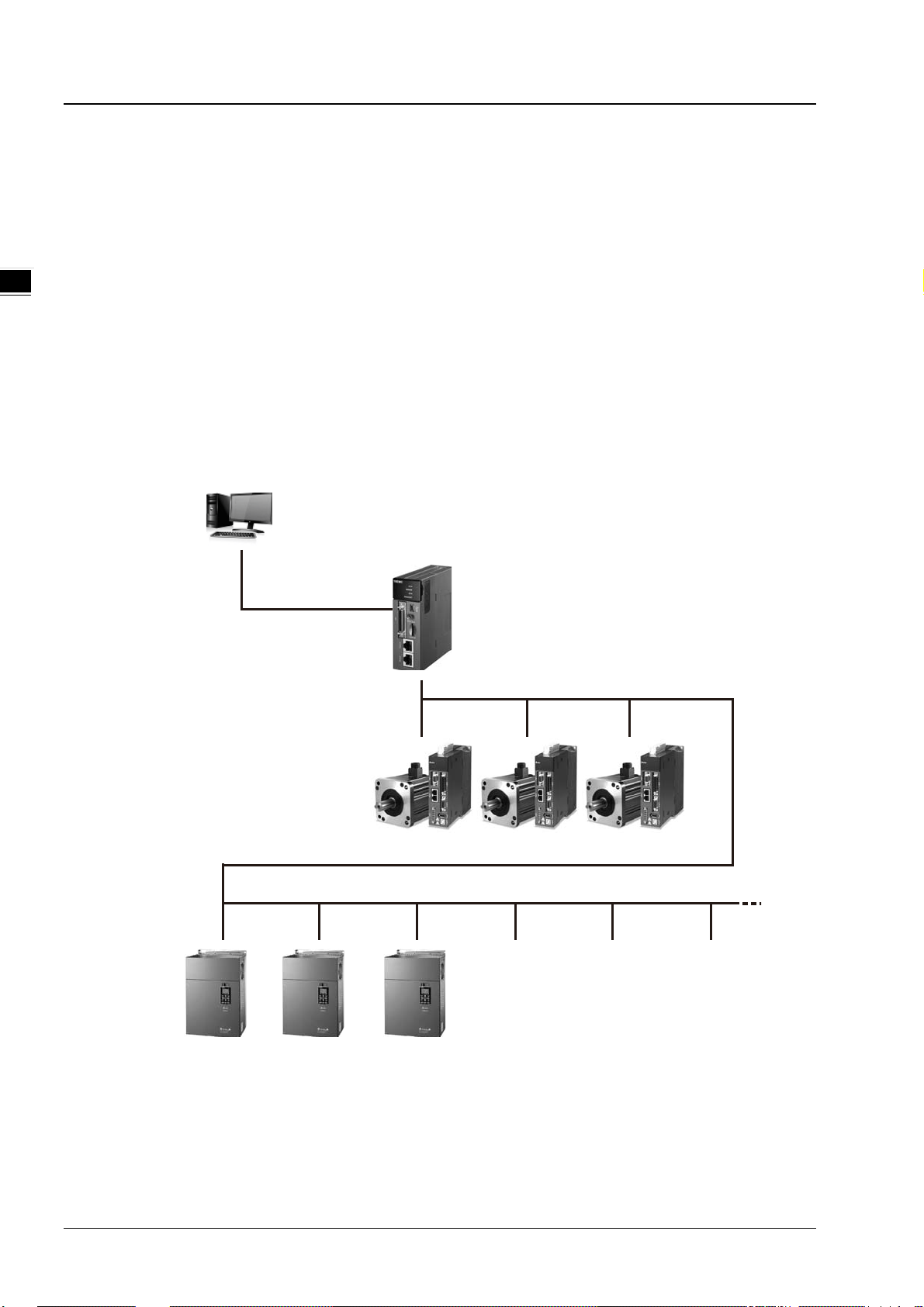
With the machine automation system that is built from Delta products, you can connect devices easily and apply the
system as a complete solution with functionality and usability.
PLC
Software
ISPSoft
AH series motion controller
1-2
Servo driv es
I
General-purpose slaves
Page 12

Chapter 1 Product Introduction
_
1.1.1. Product Features
Hardware Features
1. High performance motion control
AHxxEMC-5A features EtherCAT motion control interface and is capable of controlling up to 32 axes. Maximum 6
axes synchronous linear interpolation and 3 axes synchronous circu lar interpolation.
Supports PLCopen motion control standard function blocks.
2. High efficiency
The AH Motion CPU adopts a 32-bit high-speed processor. The instructions are executed at a speed of 0.3
milliseconds per 1k steps. (50% of the instructions are ladder instructions, and 50% of the instructions are other
standard instructions.)
3. Multiple I/O modules
The I/O modules supported by the AH Motion CPU are digital input/output modules, analog input/output modules,
temperature measurement modules, network modules, motion control modules and remote I/O modules.
1
Module Description
Digital input/output
Digital
input/output
module
Analog
input/output
module
Temperature
measurement
module
Motion control
module
Network
module
Remote I/O
Module
AH16AM10N-5A, AH16AM30N-5A, AH16AN01P-5A, AH16AN01R-5A, AH16AN01S-5A,
AH16AN01T-5A, AH16AP1 1P-5A, AH16AP1 1R-5A, AH16AP11T-5A, AH32AM10N-5A,
AH32AM10N-5B, AH32AM10N-5C, AH32AN02P-5A, AH32AN02P-5B, AH32AN02P-5C,
AH32AN02T-5A, AH32AN02T -5B, AH32AN02T-5C, AH64AM10N-5C, AH64AN02P-5C and
AH64AN02T-5C
Analog input/output
AH04AD-5A, AH04DA-5A, AH06XA-5A, AH08AD-5A, AH08AD-5B, AH08AD-5C,
AH08DA-5A, AH08DA-5B, and AH08DA-5C
Measuring the temperature
AH04PT-5A, AH04TC-5A, AH08TC-5A, and AH08PTG-5A
Controlling the motion
AH02HC-5A, AH04HC-5A, AH05PM-5A, AH10PM-5A, AH15PM-5A, AH20MC-5A
Additional communication interface
AH10SCM-5A, AH10COPM-5A, AH10EN-5A, AH15EN-5A, AH10SCM-5A, AH15SCM-5A,
AH10DNET-5A, AH10PFBS-5A, AH10PFBM-5A
It can be installed on the main backplane to work as a RTU workstation. (it supports multiple
communication ports) AHRTU-DNET-5A, AHRTU-PFBS-5A and AHRTU-ETHN-5A.
4. Larger program capacity and memory
The program capacity of the AH Motion CP U can be up to 256k steps. Users do not need to change to a more
advanced CPU if the user program grows bigger.
The AH Motion CPU offers 128k words of data registers; 64k words of D devices and 64k words of L devices.
1-3
Page 13
_
1
AH Motion Controller – Hardware Ma nual
5. Serial control interface with multiple functions
AHxxEMC-5A provides one serial interface throu gh USB: COM1.
AHBP03M2-5A/AHBP05M2-5A (AH motion backplane) provides one serial interface through terminal block:
COM2.
You can use the USB serial interface (COM1) as RS-232 and terminal block serial interface (COM2) as RS-485
according to the application. The data transfer rate can be increased from 9600 bps to 115200bps.
ISPSoft,can perform automatic data exchange simply by filling the data exchange form in the software. Users do
not need to write any program for this purpose and can save time and efforts. For details of data exchange
between devices, refer to ISPSoft User Manual.
6. Memory card
The memory card has the following functions.
System backup: for user program, CPU parameters, module tables, and setting values in devices.
System recovery: for user program, CPU parameters, module tables, and setting values in devices.
Parameter storage: The values in the devices
Log storage: The system error log and the system status log
7. Hot swap
The AH motion series I/O modules support the on-line uninterruptible hot swapping. W hen the s ystem runs, users
can replace the module with error without stopping the system or setting the module t o offline state. After the
module is replaced, the new module will resume normal operation automatically.
1-4
Page 14

Chapter 1 Product Introduction
_
Software Features
1. Complying with IEC 61131-3
The AH Motion CPU complies with IEC 61131-3 editing environment which supports various programming
languages, multiple function blocks, tasks, and symbol tables.
The programming l anguages which are supported are, structured texts (ST), ladder diagrams (LD), sequential
function charts (SFC), and Continuous Function Chart (CFC).
1
You can select a programming language according to your preference and the convenience. The programming
languages support one another so that the programs written by different users are related.
2. Various function blocks*
In addition to standard IEC61131-3 function blocks (including PLCopen motion control function blocks), we also
offer various convenient function blocks (DFB). You can write the program frequently executed in a function block
so that the program becomes more structured and can be executed more conveniently.
The encryption function supported by ISPSoft provides the secrecy of function blocks for special businesses. The
program inside a function block cannot be learned, and the patent of a business will not be infringed.
*Note: A function block is a program element equipped with the operation function. It is similar to a subroutine, and is
a type of POU (Program Organization Unit). It cannot operate by itself, and has to be called through the program POU.
After the related parameters are transmitted, the function defined by a function block is executed. Besides, the fina l
operation result can be sent to the device or variable used in the superior POU after the execution of the function
block is complete.
3. Task
The user program supports 283 tasks at most: 32 cyclic tasks, 32 I/O interrupt tasks, 212 external interrupt tasks, 1
24V LV detection, 4 timed interrupt tasks, and 2 communication interrupt tasks.
Users can enable and disable a task during the execution of a program by means of TKON and TKOFF.
4. On-line debugging mode
After a single instruction step has been complete, or after a breakpoint is specified, users can easily find the bug in
the program by means of the on-line debugging mode supported by the AH Motion CPU.
Note: Structured Text (ST) do not support on-line debugging mode, and sequential function charts (SFC)
programming support the debugging mode during the action and the transition.
1-5
Page 15

AH Motion Controller – Hardware Ma nual
_
5. On-line editing mode
When the system runs, users can make use of the on-line editing mode to update the program without affecting
the operation of the system.
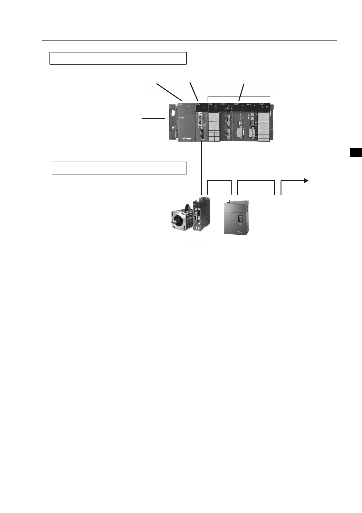
1.1.2. Overview of the System Configurations
1
The two categories of system configurations of AH Motion series motion control CPU are as follows.
Basic System Configurations
The AH Motion series CPU basic configurations include the AH Motion CPU Network Configuration, AH500 Series
Module Configuration, and Supported Software.
AH Motion Network Configuration
- AHxxEMC-5A
You can use the EtherCAT master port built in on the CPU interface to connect to slave devices such as analog and digital
I/O, servo drives, AC motor drives and encoder input devices. With EtherCAT network configuration, you can design a
system capable of performing very accurate sequence and motion control in a fixed cycle.
AH500 Series Module Configuration
With the motion backplane, you can also add AH500 series I/O modules* in addition to the EtherCAT network. AH500
series modules can be installed directly to the motion backplane where the CPU module is mounted.
*Note: a few of AH500 series I/O modules are not supported by the motion backplane. Refer to Ch2 System
Configuration for the list of supported products.
Supported Software
ISPSoft is the major programming software that you use for an AH Motion series motion controller. You can connect the
software on the computer to the USB interface on the CPU module through a commercially available USB cable. You can
also connect ISPSoft to the Ethernet port on the CPU module with an Ethernet cable or to the built-in RS-485 port on the
Motion backplane with a RS-485 cable and a converting device, e.g. IFD6500 USB/RS-485 converter. In addition to
ISPSoft, you can also use other software for configuring various applications based on different networks.
1-6
Page 16
_
Support Software
ISPSoft
AH Motion CPU
Power
Supply
CPU
Chapter 1 Product Introduction
AH500 Series Module
Configuration
AH I/O modules
USB(RS- 232)
LAN or EtherNet/IP
CPU
Rack
AH MotionNetwork
Bullt-In EtherCAT port
Bullt- In Ether Net/IP port
EtherCAT
Servo drives/encoder
input slaves
General-purpose slaves
Configuration
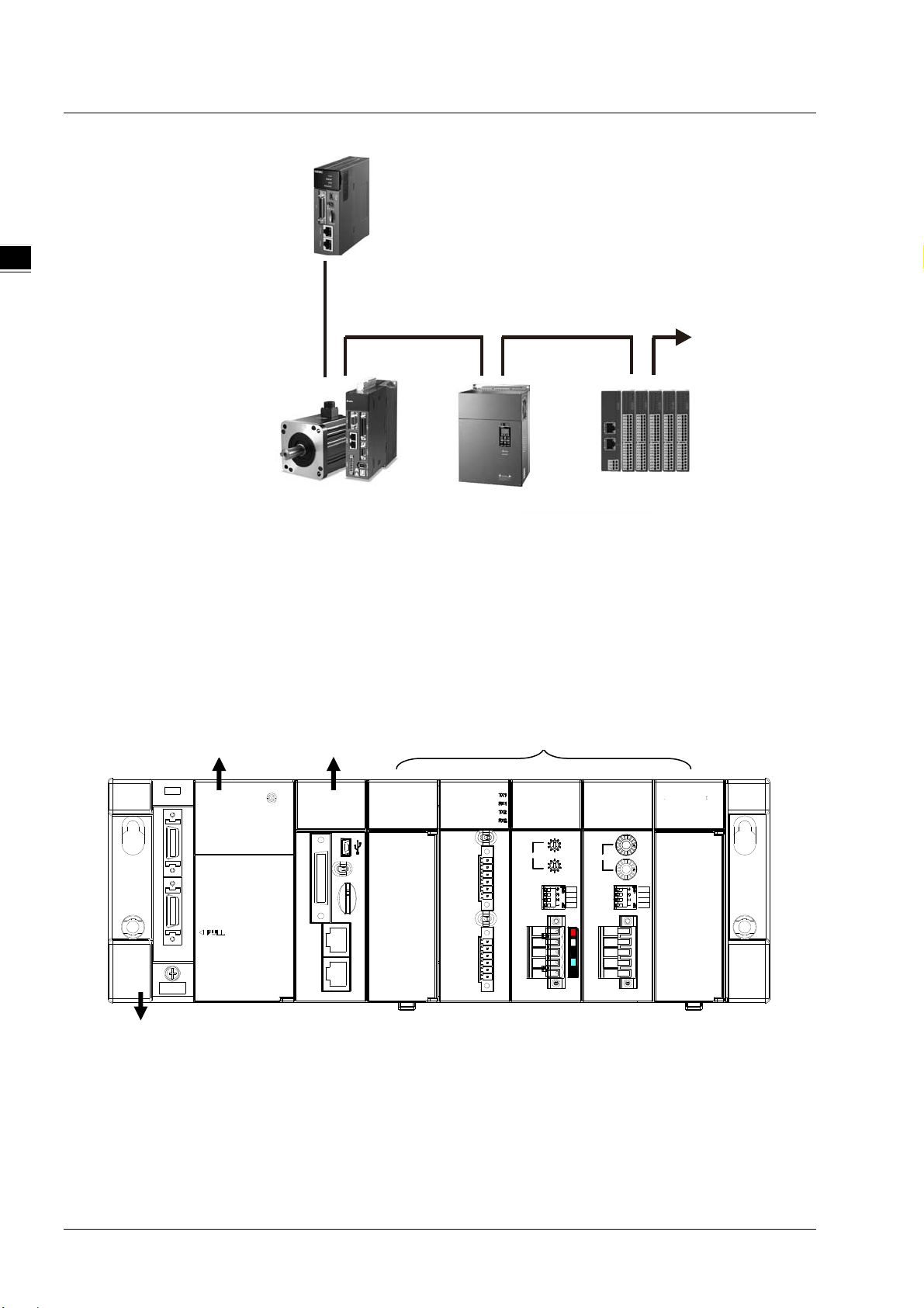
Other Network Configurations
Through the network interfaces on the AH motion CPU and the m otion backplane, you can connect host computers,
Human Machine Interfaces (HMI) and other AH series PLCs with RS-232(USB), RS-485, and EtherNet/IP networks. In
addition, you can also create CANopen network and additional serial communication network (RS-485) by mounting
AH500 series network modules on the motion backplane.
PC HMI
1
Et herNet/IP Scanner
( A H 500 Se r i es PLC )
DVS Series
Et h er n et Sw i tch
EtherNet/IP (Adapter)
USB RS-485
Power CPU
Serial Comm.
Module
CANopen
Module
CANo penSerial communications
1-7
Page 17

AH Motion Controller – Hardware Ma nual
_
Supported Software
ISPSoft is the major programming software that you use for an AH Motion series motion controller. You can use ISPSoft to
set up the controller configurations, parameters, and to develop the program. Debugging and simulate operation.
Required software
1
- ISPSoft: Programming and hardware configuration
- COMMGR: Communication management
- EtherCAT Builder: EtherCAT network configurator (for AHxxEMC-5A)
Optional software
- EtherNet/IP Builder: EtherNet/IP network configurator
- CANopen Builder: CANopen network configurator
1.2 AH Motion CPU Specifications
1.2.1 Environmental Specifications
Environmental Specifications
Operating temperature
Storage temperature
Operating humidity
-20~60°C
-40~70°C
5~95%
No condensation
Storage humidity
Vibration/Shock
resistance
Operating environment
Installation location
Pollution degree
5~95%
No condensation
International standards IEC 61131-2, IEC 68-2-6 (TEST Fc)/
IEC 61131-2 & IEC 68-2-27 (TEST Ea)
No corrosive gas exists.
In a control box
2
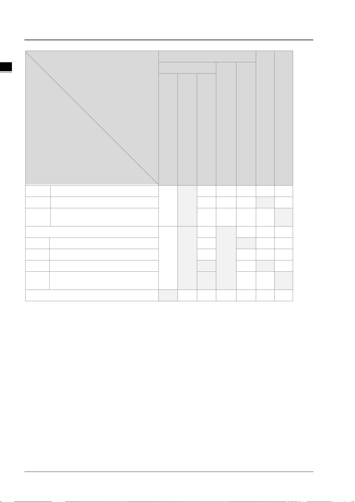
1.2.2 General Specifications
General Specifications
AHxxEMC-5A Remark
Execution
Input/Output control
Programming language
The program is executed cyclically.
Cyclically refreshed inputs/outputs
Direct inputs/outputs
IEC 61131-3
The inputs and outputs can be
controlled through the direct
inputs (DX device) and direct
outputs (DY device).
1-8
Page 18

Chapter 1 Product Introduction
_
General Specifications
AHxxEMC-5A Remark
Ladder diagram (LD), continuous function
chart (CFC), structured text (ST), and
sequential function chart (SFC).
Instruction execution speed
Constant scan cycle (ms)
Program capacity (step)
Installation
Installation of modules
Number of modules
Number of tasks
Number of input/output
devices
Number of inputs/outputs
0.3 ms/K steps
1-32000
(The scan cycle can be increased by one
millisecond.)
256K steps
DIN rails or screws
Modules are installed directly on a backplane.
Five input/output modules at most can be
installed on a motion backplane.
283 tasks (32 cyclic tasks, 32 I/O interrupt
tasks, 212 external interrupt tasks, 1 24V LV
detection, 4 timed interrupt tasks, and 2
communication interrupt tasks).
X/Y devices (bit): 8192
(X0.0~X511.15/Y0.0~Y511.15)
X/Y devices (word): 512
(X0~X511/Y0~Y511)
338 inputs/ 324 outputs (AHBP05M2-5A)
1
The scan cycle time can be
specified by parameters.
Number of devices which can be
used in a program
Number of inputs/outputs
accessible to an CPU
Input relay [X]
Output relay [Y]
Auxiliary relay [M]
Timer [T]
Counter [C]
32-bit counter [HC/AC]
Data register [D]
Stepping relay [S]
Index register [E]
Special auxiliary relay [SM]
Special data register [SR]
Serial communication port
Ethernet port
8192 (X0.0~X511.15)
8192 (Y0.0~Y511.15)
8192 (M0~M8191)
2048 (T0~T2047)
2048 (C0~C2047)
HC: 64 (HC0~HC63)
AC: 56 (AC0~ AC55)
D device (bit): 1048576 (D0.0~D65535.15)
D device (word): 65536 (D0~D65535)
2048 (bit) (S0~S2047)
32 (word) (E0~E31)
SM(bit): 2048 (SM0~SM2047)
SR(word): 2048 (SR0~SR2047)
One RS-232(USB), One RS-485
communication port
10/100 M
1-9
Page 19

AH Motion Controller – Hardware Ma nual
_
General Specifications
AHxxEMC-5A Remark
1
USB port
Memory card slot
Real-time clock
Mini USB
Supports Micro SD card (SD 2.0)
Years, months, days, hours, minutes,
seconds, and weeks
The function is available when the
CPU is used together with the
motion backplane
1-10
Page 20

2
Chapter 2 System Configuration
Table of Contents
2.1 Basic System Configuration ........................................................................ 2-2
2.1.1. AH Motion CPU Network Configuration ......................................................... 2-3
2.1.2. AH500 Series Module Configuration ............................................................. 2-4
2.2 Software Connection ................................................................................ 2-10
2.3 Overall Network Configuration ................................................................. 2-11
2.3.1 EtherNet/IP ................................................................................................. 2-12
Page 21

AH Motion Controller – Hardware Ma nual
_2
2.1 Basic System Configuration
An AH Motion series CPU provides two types of configurations as follows.
1. Basic Configurations
The basic configurations explained in this section include the CPU network configuration and the configuration of the I/O
modules which are controlled by the CPU.
- AH Motion CPU network configuration
- AH500 Series Module Configuration
2. Other Network Configurations
In addition to the main CPU network configuration, you can also set up other network configurations which are connecte d
to the CPU’s built-in EtherNet/IP port and other network modules.
AH Motion CPU Network Configuration
- AHxxEMC
The AH Motion CPU provides EtherCAT network as a basic motion system.
With the EtherCAT network system, you can obtain execution results of both sequence and motion control operation in the
high speed communications period of EtherCAT network. This feature enables precise sequence control and motion
control with a constant cycle time and steady operational results.
AH500 Series Module Configuration
CPU Rack
The CPU Rack consists of products as follows.
- AH Motion series CPU
- AH Motion series backplane
- AH500 series power supply module
- AH500 series motion control modules
- AH500 series network modules*
- AH500 series digital I/O modules and special I/O modules.
*Note: Some AH500 series network modules are not supported by AH Motion CPU. Refer to 2.1.2 AH500 Series Module
Configuration for the supported models.
Page 22
_
AH500 Series Module Configuration
C
Chapter 2 System Configuration
Power supply module
Motion backplane
AH Motion CPU Network Configuration
EtherCAT slaves
AH Motion CPU
EtherCAT network
configuration(AH10EMC)
Servo Drives
2.1.1. AH Motion CPU Network Configuration
Digital I/O, Special I/O
Inverters General-prupose slave s
2
AHxxEMC – EtherCAT
The EtherCAT network configuration includes AHxxEMC which is the core motion CPU, an AH motion backplane*, and an
AH500 series power supply module. You can connect the built-in EtherCAT master port to the EtherCAT slave devces.
The AHxxEMC can also be used as a motion control module in an AH500 series PLC configuration. You can install it onto
the AH500 series main backplane to perform motion control function.
For more information about this application, refer to AH500 Motion Control Module Manual.
*Note: The AH motion backplane must be used together with AHxxEMC when you use AHxxEMC as a motion CPU.
2-3
Page 23
AH Motion Controller – Hardware Manual
_2
A
HMotionCPU
EtherCAT
1
EtherCAT sla ves
Servo drives General-purpose slaves
Inverters
2.1.2. AH500 Series Module Configuration
The AH Motion CPU rack consists of a motion backplane with a power supply module and a motion CPU. You can mount
additional AH500 series moudles to the right for different applications. T he available modules include d igital input/output
modules, analog input/output modules, network modules, and motion control modules.
AH Motion CPU Rack
A CPU module, a power supply module, and I/O modules are installed on a motion backplane.
Powre supply module
AH Motion CPU
10EMC
BUS FAULT
CN1
Ethernet EtherCAT
ERROR
SYSTEM
RUN
RUNSTOP
Micro SD
06XA 10SCM
ERROR
RUN
AH500 series modules
10DNET
RUN
ERROR
COM1 RS485
COM2 RS485
TR1
TR2
OFF
ON
COM1
TX+
TXRX+
RX-
FG
ON
COM2
TX+
TXRX+
RXGND
FG
Node Address
D+
DGNDGND
FG
OFF
D+
DGND
FG
10COPM
MS
NS
5
6
4
7
1
3
x10
8
2
9
1
0
5
Node Address
6
4
7
0
3
x10
8
2
9
1
0
DR 1
DR 0
IN 1
IN 0
ERROR
16AN01T
RUN
312
0
5
124910
118
15147613
1
x16
0
x16
DR 2
DR 1
DR 0
IN 0
CAN+
SHLD
CAN-
GND
AH Motion backplane
2-4
Page 24

Chapter 2 System Configuration
_
Components
Component Model Name Description
Power supply
module
AH Motion
CPU
Motion
backplane
AHPS05-5A
AHPS15-5A 24 VDC
AHxxEMC-5A
AHBP03M2-5A Three slots available for additional AH500 series modules.
AHBP05M2-5A Five slots available for additional AH500 series modules.
AHBP07M2-5A Seven slots available for additional AH500 series modules.
AH16AM10N-5A
AH32AM10N-5A
100~240 VAC
50/60 Hz
AH08EMC-5A: 8 axes; AH10EMC-5A: 16 axes; AH20EMC-5A: 32 axes
One EtherCAT port
One EtherNet/IP port (adapter)
One built-in USB port (RS-232)
One built-in micro SD interface
24 VDC
5 mA
16 inputs
Terminal block
24 VDC
5 mA
32 inputs
Terminal block
2
Digital
input/output
module
AH32AM10N-5B
AH32AM10N-5C
AH64AM10N-5C
AH16AM30N-5A
AH16AN01R-5A
24 VDC
5 mA
32 inputs
DB37 connector
24 VDC
5 mA
32 inputs
MIL connector
24 VDC
3.2 mA
64 inputs
MIL connector
100~240 VAC
4.5 mA~9 mA (100 V, 50 Hz)
16 inputs
Terminal block
240 VAC/24 VDC
2 A
16 outputs
Relay
Terminal block
2-5
Page 25

AH Motion Controller – Hardware Manual
_2
Component Model Name Description
12~24 VDC
0.5 A
AH16AN01T-5A
AH16AN01P-5A
AH32AN02T-5A
AH32AN02T-5B
16 outputs
Sinking output
Terminal block
12~24 VDC
0.5 A
16 outputs
Sourcing output
Terminal block
12~24 VDC
0.1 A
32 outputs
Sinking output
Terminal block
12~24 VDC
0.1 A
32 outputs
Sinking output
DB37 connector
AH32AN02T-5C
AH32AN02P-5A
AH32AN02P-5B
AH32AN02P-5C
12~24 VDC
0.1 A
32 outputs
Sinking output
MIL connector
12~24 VDC
0.1 A
32 outputs
Sourcing output
Terminal block
12~24 VDC
0.1 A
32 outputs
Sourcing output
DB37 connector
12~24 VDC
0.1 A
32 outputs
Sourcing output
MIL connector
12~24 VDC
0.1 A
AH64AN02T-5C
2-6
64 outputs
Sinking output
MIL connector
Page 26

Chapter 2 System Configuration
_
Component Model Name Description
12~24 VDC
0.1 A
AH64AN02P-5C
AH16AN01S-5A
AH04AD-5A
AH08AD-5A
64 outputs
Sourcing output
MIL connector
100~240 VAC
0.5 A
16 outputs
TRIAC
Terminal block
Four-channel analog input module
Hardware resolution: 16 bits
0/1 V~5 V, -5 V~5 V, 0 V~10 V, -10 V~10 V, 0/4 mA~20 mA, and -20
mA~20 mA
Conversion time: 150 us/channel
Eight-channel analog input module
Hardware resolution: 16 bits
0/1 V~5 V, -5 V~5 V, 0 V~10 V, -10 V~10 V, 0/4 mA~20 mA, and -20
mA~20 mA
Conversion time: 150 us/channel
2
Analog
input/output
module
AH08AD-5B
AH08AD-5C
AH04DA-5A
AH08DA-5A
AH08DA-5B
AH08DA-5C
Eight-channel analog input module
Hardware resolution: 16 bits
0/1 V~5 V, -5 V~5 V, 0 V~10 V, and -10 V~10 V
Conversion time: 150 us/channel
Eight-channel analog input module
Hardware resolution: 16 bits
0/4 mA~20 mA, and -20 mA~20 mA
Conversion time: 150 us/channel
Four-channel analog output module
Hardware resolution: 16 bits
0/1 V~5 V, -5 V~5 V, 0 V~10 V, -10 V~10 V, and 0/4 mA~20 mA
Conversion time: 150 us/channel
Eight -channel analog output module
Hardware resolution: 16 bits
0/1 V~5 V, -5 V~5 V, 0 V~10 V, -10 V~10 V, and 0/4 mA~20 mA
Conversion time: 150 us/channel
Eight-channel analog output module
Hardware resolution: 16 bits
0/1 V~5 V, -5 V~5 V, 0 V~10 V, and -10 V~10 V
Conversion time: 150 us/channel
Eight-channel analog output module
Hardware resolution: 16 bits
0/4 mA~20 mA
Conversion time: 150 us/channel
AH06XA-5A
Four-channel analog input module
Hardware resolution: 16 bits
0/1 V~5 V, -5 V~5 V, 0 V~10 V, -10 V~10 V, 0/4 mA~20 mA, and -20
mA~20 mA
2-7
Page 27

AH Motion Controller – Hardware Manual
_2
Component Model Name Description
Conversion time: 150 us/channel
Two-channel analog output module
Hardware resolution: 16 bits
0/1 V~5 V, -5 V~5 V, 0 V~10 V, -10 V~10 V, and 0/4 mA~20 mA
Conversion time: 150 us/channel
Four-channel four-wire/three-wire RTD
Sensor type: Pt100/Pt1000/Ni100/Ni1000 sensor, and 0~300 Ω input
impedance
Temperature
measurement
module
AH04PT-5A
AH08PTG-5A
AH04TC-5A
Resolution: 0.1°C/0.1°F (16 bits)
Four-wire conversion time: 150 ms/channel
Three-wire conversion time: 300 ms/channel
Eight-channel four-wire/three-wire/two-wire RTD
Sensor type: Pt100/Pt1000/Ni100/Ni1000, and 0~300 Ω input impedance
Resolution: 0.1°C/0.1°F (16 bits)
Conversion time: 20 ms/4 channels and 200 ms/8 channels
Four-channel thermocouple
Sensor type: J, K, R, S, T, E, N, and -150~+150 mV
Resolution: 0.1°C/0.1°F
Conversion time: 200 ms/channel
Motion control
module
Network
module
Eight-channel thermocouple
AH08TC-5A
AH02HC-5A Two-channel high-speed counter module (200 kHz)
AH04HC-5A Four-channel high-speed counter module (200 kHz)
AH05PM-5A Two-axis pulse train motion control module (1 MHz)
AH10PM-5A
AH15PM-5A Four-axis pulse train motion control module (1 MHz )
AH20MC-5A
AH10EN-5A
AH15EN-5A
AH10SCM-5A
Sensor type: J, K, R, S, T, E, N, and -150~+150 mV
Resolution: 0.1°C/0.1°F
Conversion time: 200 ms/channel
Six-axis pulse train motion control module
(Four axes: 1 MHz; Two axes: 200 kHz)
Twelve-axis DMCNET (Delta Motion Control Network) motion control
module (10 Mbps)
It is an Ethernet communication module with two Ethernet ports, and
supports Modbus TCP protocols, and EtherNet/IP software (V2.0). It can
function as a master or a slave.
It is an Ethernet communication module with two Ethernet ports, and
supports Modbus TCP protocols, and IEC60870-5-104. It can function as a
master or a slave.
It is a serial communication module with two RS-485/RS-422 ports, and
supports Modbus and UD Link protocols. One part of communication is
isolated from the other part of the communication, and one part of power
is isolated from the other part of the power.
It is a serial communication module with two RS-232 ports, and supports
AH15SCM-5A
AH10DNET-5A
2-8
Modbus and UD Link protocols. One part of communication is isolated
from the other part of the communication, and one part of power is
isolated from the other part of the power.
It is a DeviceNet communication module. It can function as a master or
slave. A maximum of 1Mbps per second can be transferred.
Page 28

Chapter 2 System Configuration
_
Component Model Name Description
AH10PFBM-5A It is a PROFIBUS communication module. It can function as a master.
AH10PFBS-5A It is a PROFIBUS communication module. It can function as a slave.
Remote I/O
module
I/O extension
cable
AH10COPM-5A
AHRTU-DNET-5A It is a DeviceNet remote I/O communication module.
AHRTU-PFBS-5A It is a PROFIBUS remote I/O communication module.
AHRTU-ETHN-5A It is an Ethernet remote I/O communication module.
UC-ET010-24A or
DVPACAB7A10
UC-ET010-24C or
DVPACAB7B10
UC-ET010-33B or
DVPACAB7C10
UC-ET010-13B or
DVPACAB7D10
UC-ET010-15B or
DVPACAB7E10
UB-10-ID32A or
DVPAETB-ID32A
UB-10-OR16A or
DVPAETB-OR16A
It is a CANopen communication module. It can function as a master or a
slave.
1.0 meter I/O extension cable (MIL connector) for AH32AM10N-5C and
AH64AM10N-5C
1.0 meter I/O extension cable (MIL connector) for AH32AN02T-5C,
AH32AN02P-5C, AH64AN02T-5C and AH64AN02P-5C
1.0 meter I/O extension cable (DB37 connector) for AH32AM10N-5B,
AH32AN02T-5B, and AH32AN02P-5B
1.0 meter I/O extension cable for AH04HC-5A and AH20MC-5A
1.0 meter I/O extension cable for AH10PM-5A and AH15PM-5A
I/O external terminal module for AH32AM10N-5C and AH64AM10N-5C
32 inputs
I/O external terminal module for AH32AN02T-5C and AH64AN02T-5C
16 relay outputs
2
External
terminal
module
UB-10-OR16B or
DVPAETB-OR16B
UB-10-ID32B or
DVPAETB-ID32B
UB-10-OR32A or
DVPAETB-OR32A
UB-10-OR32B or
DVPAETB-OR32B
UB-10-OT32A or
DVPAETB-OT32A
UB-10-OT32B or
DVPAETB-OT32B
UB-10-IO16C or
DVPAETB-IO16C
UB-10-IO24C or
DVPAETB-IO24C
UB-10-IO34C or
DVPAETB-IO34C
I/O external terminal module for AH32AN02P-5C and AH64AN02P-5C
16 relay outputs
I/O external terminal module for AH32AM10N-5B
32 inputs
I/O external terminal module for AH32AN02T-5B
32 relay outputs
I/O external terminal module for AH32AN02P-5B
32 relay outputs
I/O external terminal module for AH32AN02T-5C, AH32AN02P-5C,
AH64AN02T-5C, and AH64AN02P-5C
32 transistor outputs
I/O external terminal module for AH32AN02T-5B and AH32AN02P-5B
32 transistor outputs
I/O external terminal module for AH04HC-5A and AH20MC-5A
I/O external terminal module for AH10PM-5A
I/O external terminal module for AH10PM-5A
2-9
Page 29

AH Motion Controller – Hardware Manual
_2
LCSof
Component Model Name Description
Dummy
module
AHASP01-5A Dummy module used for an empty I/O slot
2.2 Software Connection
Through the network interfaces on the AH motion CPU and the motion backplane, you can connect the CPU to the host
computer with RS-232(USB), RS-485, and Ethernet networks. In this configuration, you can also connect ISPSoft with
AH500 series PLCs. Refer to
Motion system and the ISPSoft.
ISPSoft User Manual
for information on the procedures of the connections between the AH
P
tware
ISPSoft
EtherNet/I P Ne twork
therNet/IP Scanner
RS-232
RS-485
AH500 AH Motion/
series PLCs
AH Motion CPU
2-10
Page 30

Chapter 2 System Configuration
_
I
nform
ati
o
a
yer
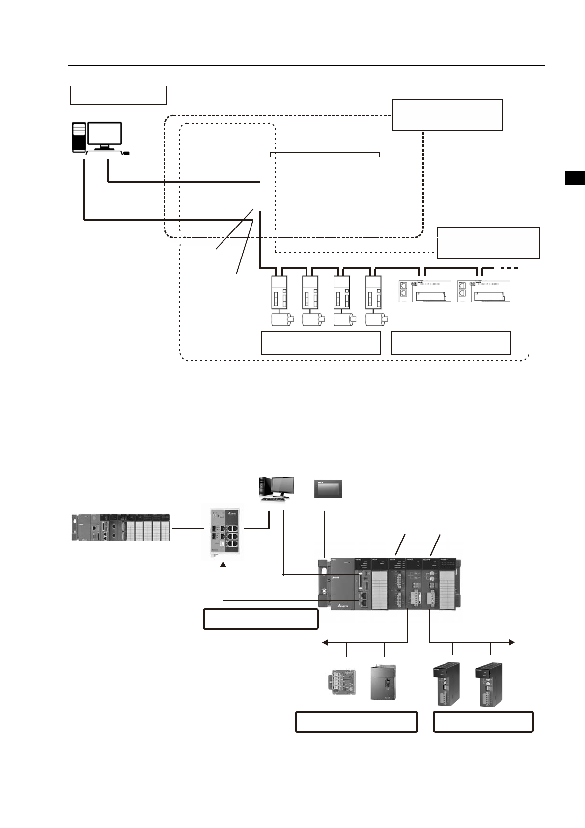
2.3 Overall Network Configuration
- AHxxEMC
In addition to the AH Motion CPU network, e.g. EtherCAT, you can expand AH Motion system with additional networks
such as CANopen network and serial communication networks. The diagram below shows the overall network
configuration of different layers.
For operation procedures on connecting different communication networks, refer to ISPSoft User Manual.
n L
EtherNet/IP
Control Layer
EtherNet/IP
AH Motion CPU
Serial
communication
module
CANopen module
PC
AH500 series CPU
Bu ilt-in
EtherNet/IP port
CANopen
EtherNet/IP module port
Built-in EtherNet/IP port
AH Motion CPU
HMI
Buil t-in
EtherNet/IP port
Built-in
EtherCAT port
EtherCAT
2
Robot
Device Layer
Servo Drives
Serial communications
RS-422/R S- 485 seri al-com m uni cat ons devices
Servo Drives
EtherCAT slaves
2-11
Page 31

AH Motion Controller – Hardware Manual
_2
Layer Function Network type Protocols Devices
Message communications
Information Layer
Control Layer
Device Layer -
field networks
(CIP) with host personal
computer
Automatic data exchange
between controllers (no
programming required)
Communication between
PLC and devices with
serial interface.
High-speed, high accuracy
communications with servo
drives and slaves(32 axes)
High-speed, high accuracy
communications with servo
drives and slaves (16
axes)
EtherNet/IP
EtherNet/IP
MODBUS TCP
Serial communications
Serial communications
EtherCAT EtherCAT protocol
CANopen CANopen protocol CANopen module
2.3.1 EtherNet/IP
Please refer to EtherNet/IP operation manual for more details.
CIP message
communications
EtherNet/IP
MODBUS TCP
MODBUS
RS-422/RS-485
MODBUS
RS-422/RS-485
Built-in EtherNet/IP
port
Delta controllers
Serial communication
module
Built-in EtherCAT
port
2-12
Page 32

3
Chapter 3 Product Specifications
Table of Contents
3.1 Environmental Specificatio ns ..................................................................... 3-2
3.2 AH Motion CPU ........................................................................................... 3-2
3.2.1 General Specifications ............................................................................... 3-2
3.2.2 Motion Control Function Specifications ......................................................... 3-5
3.2.3 Communication Ports ................................................................................ 3-6
3.2.4 I/O Addressing of AH Motion CPU ................................................................ 3-7
3.2.5 Profiles ................................................................................................ 3-14
3.2.6 Dimensions ............................................................................................ 3-15
3.2.7 Arrangement of Terminals ........................................................................ 3-16
3.2.8 Memory Card Slot ................................................................................... 3-16
3.3 I/O Modules ............................................................................................. 3-17
3-1
Page 33

AH Motion Controller – Hardware Manual
_3
Environmental Specifications
Operating temperature
Storage temperature
-40~70°C
No condensation
No condensation
resistance
IEC 61131-2 & IEC 68-2-27 (TEST Ea)
Operating environment
Installation location
In a control box
Pollution degree
2
General Specifications
AHxxEMC-5A
Remark
Execution
The program is executed cyclical ly.
device).
sequential function chart (SFC ) .
Instruction execution speed
Program capacity (step)
256K steps
Installation
DIN rails or screws
installed on a motion backplane.
communication interrupt tasks).
3.1 Environmental Specifications
-20~60°C
Operating humidity
Storage humidity
Vibration/Shock
5~95%
5~95%
International standards IEC 61131-2, IEC 68-2-6 (TEST Fc)/
No corrosive gas exists.
3.2 AH Motion CPU
3.2.1 General Specifications
AHxxEMC-5A
Input/Output control
Cyclically refreshed inputs/outputs
Direct inputs/outputs
The inputs and outputs can be
controlled through the direct inputs
(DX device) and direct outputs (DY
Programming language
Constant scan cycle (ms)
Installation of modules
Number of modules
Number of tasks
IEC 61131-3
Ladder diagram (LD), continuous f unction
chart (CFC), structured text (ST), and
0.3 ms/K steps
1-32000
(The scan cycle can be increased by one
millisecond.)
Modules are installed directly on a
backplane.
Five input/output modules at most c an be
283 tasks (32 cyclic tasks, 32 I/O interrupt
tasks, 212 external interrupt tasks, 1 24V LV
detection, 4 timed interrupt tasks, and 2
The scan cycle time can be
specified by parameters.
3-2
Page 34

3_
General Specifications
AHxxEMC-5A
Remark
Number of input/output
(X0~X511/Y0~Y511)
accessible to an CPU
Input relay [X]
Output relay [Y]
8192 (Y0.0~Y511.15)
Auxiliary relay [M]
8192 (M0~M8191)
Timer [T]
2048 (T0~T2047)
Counter [C]
2048 (C0~C2047)
AC: 56 (AC0~ AC55) (AHxxEMC)
D device (word): 65536 (D0~D65535)
Stepping relay [S]
Index register [E]
32 (E0~E31)
Special auxiliary relay [SM]
SM: 2048 (SM0~SM2047)
Special data register [SR]
communication port
Ethernet port
10/100 M
USB port
Mini USB
Memory card slot
Supports Micro SD card (SD 2.0)
motion backplane
Weight
230g
Rated input
Current
Voltage
1. Differential input terminals.
captures.
devices
X/Y devices (bit): 8192
(X0.0~X511.15/Y0.0~Y511.15)
X/Y devices (word): 512
Chapter 3 Product Specifications
Number of devices which can be
used in a program
Number of inputs/outputs
32-bit counter [HC/AC]
Data register [D]
Serial communication port
328 inputs/ 324 outputs (AHxxEMC)
8192 (X0.0~X511.15)
HC: 64 (HC0~HC63)
D device (bit): 1048576 (D0.0~D65535.15)
2048 (S0~S2047)
SR: 2048 (SR0~SR2047)
One RS-232(USB), One RS-485
Number of inputs/outputs
Real-time clock
Description of the terminals
Terminal Description
X0.0+, X0.0-,
X0.1+, X0.1(*2)
Years, months, days, hours, minutes,
seconds, and weeks
2. The functions of the terminals:
High-speed count:
The terminals are the RESET input
terminals for counter 0~counter 1.
X0.0+ and X0.0- are for counter 0.
X0.1+ and X0.1- are for count er 1.
High-speed capture: The terminals can
function as trigger signals for hig h-speed
The function is available when the
CPU is used together with the
Response
characteristic
1MHz +/-5mA +/-5V
3-3
Page 35

AH Motion Controller – Hardware Manual
_3
Rated input
Current
Voltage
Interrupt inputs
1. Differential input terminals.
Interrupt inputs
interrupt inputs.
Y0.8,
Y0.11
function as high-speed comparison outputs.
Terminal Description
1. Common input terminals.
2. The functions of the terminals:
High-speed count:
The terminals are the RESET input
X0.2, X0.3,
X1.4, X1.5
(*2)
X0.8+, X0.8-,
X0.9+, X0.9(*2)
High-speed capture: X0.2 and X0.3 can function
1. Differential input terminals.
2. The functions of the terminals:
Motion control: The terminals are for a manual
High-speed count:
High-speed capture: The terminals can function
terminals for counter 2~counter 5.
X0.2 is for counter 2.
X0.3 is for counter 3.
X1.4 is for counter 4
X1.5 is for counter 5
as trigger signals for high-speed captures.
pulse generator.
The terminals are for counter 0.
X0.8+ and X0.8- are the A-phase inputs for
counter 0. X0.9+ and X0.9- are the
B-phase inputs for counter 0.
as trigger signals for high-speed captures.
Response
characteristic
100kHz(*1) 5mA 24V
1MHz +/-5mA +/-5V
2. The functions of the terminals:
X0.10+, X0.10-,
X0.11+, X0.11(*2)
1. Common input terminals.
2. The functions of the terminals:
X0.12,
X0.13,
X0.14,
X0.15,
X1.0,
X1.1,
X1.2,
X1.3
(*2)
1. Pulse output temrinals (ope n c ol lector).
Y0.9,
Y0.10,
2. The function of the terminals:
High-speed count:
The terminals are for counter 1.
X0.10+ and X0.10- are the A-phase inputs
for counter 1. X0.11+ and X0.11- are the
B-phase inputs for counter 1.
High-speed capture: The terminals can function
as trigger signals for high-speed captures.
High-speed count:
The terminals are for counter 2~counter 5.
X0.12 and X0.13 are for counter 2.
X0.14 and X0.15 are for coun ter 3.
X1.0 and X1.1 are for counter 4.
X1.2 and X1.3 are for counter 5.
High-speed capture: The terminals can function
as trigger signals for high-speed captures.
Interrupt inputs:
X0.12, X0.13, X0.14 and X0.15 can function as
High-speed comparison: The terminals can
1MHz +/-5mA +/-5V
100 kHz(*1) 5mA 24 V
200 kHz 15 mA 24 V
3-4
Page 36

Chapter 3 Product Specifications
3_
Specifications
AHxxEMC-5A
supported
(Axis 1~axis 32)
Storage
The capacity of the built-in storage is 256K steps.
Unit
Open collector output:200KHz
Specifications
AHxxEMC-5A
Operating switch
RUN-STOP switch
Output terminal
Y0.8, Y0.9, Y0.10, and Y0.11
EtherCAT port
The maximum capacity is 32 GB.
You can use them freely.
Number of counters
6
capture/comparison
*1. If the frequency of input signals received by an input terminal must be 200 kHz, the input termi nal must be connected
to a 1 kΩ (2 W) resistor in parallel
*2. From HWCONFIG of the ISPSoft, two different filter settings for IO inputs can be set, X Input Sing le Filter Time and X
Input Single Frequency Filter Fac tor. For details, please refer to section 4.4.4.1 in the AH Motion Controller Operation
Manual.
3.2.2 Motion Control Function Specifications
AHxxEMC-5A
Number of substantial axes
Motor control
Maximum speed
Input
signal
Input terminal
AH08EMC-5A: 8 axes; AH10EMC-5A: 16 axes; AH20EMC-5A: 32 axes
Motor unit, mechanical unit
High-speed motion control system EtherCAT
The response time is 100Mbps.
EtherCAT: 100M bps
Diffrential input: 1MHz
Open collector input : 200KHz
X0.0+, X0.0-,
X0.1+, X0.1-,
X0.8+, X0.8-,
X0.9+, X0.9-, X0.10+, X0.10-, X0.11+, X0. 11-, X0.2, X0.3, X0.12,
X0.13, X0.14, X0.15,
X1.0,X1.1, X1.2, X1.3, X1.4, X1.5,
Output
signal
Memory card slot
M-code
G-code
Number of high-speed
External
communication port
Mini USB port
Ethernet port
Supports Micro SD card
M00~M01, M03~M101, and M103~M6553 5: The execution of a program pauses.
(WAIT)
G0 (rapid positioning), G1 (linear i nterpolation), G2 (circular interpolation,
clockwise), G3 (circular interp ol ation, counterclockwise), G4 (dwell), G17 (XY
plane selection), G18 (ZX plane selection), G19 (YZ plane selection), G90
(absolute programming), and G 91 ( i nc remental programming)
6
3-5
Page 37

AH Motion Controller – Hardware Manual
_3
Specifications
AHxxEMC-5A
Number of interrupt devices
Specifications
Electrical isolation
500 VDC
Connector
RJ45
Transmission cable
CAT-5, CAT-5e, CAT-6
Specifications
Electrical isolation
500 VDC
Connector
RJ45
UC-EMC200-02 (20M)
216
3.2.3 Communication Ports
AHxxEMC-5A
AHxxEMC is equipped with a mini USB port and an Ethernet port and an EtherCAT port.
Mini USB: A mini USB port can function as a slave statio n. You can download or upload a pr ogram throug h a mini USB
port. The communication protoc ols supported by the mini USB port are MODBUS ASCII and MODBUS RTU
(RS-232).
Ethernet: The Ethernet port supp orts communication protocol MODBUS TCP and EtherNet/IP adapter.
MODBUS TCP
The Ethernet port on AH Motion CPU c an exchange data with a device with Ethern et interface, e.g. AH500
series PLCs, through a common Ethernet cable.
- Can be c onnected to ISPSoft. A program can be uploaded/downloa ded and monitored.
- Can also function as a standard MODBUS TCP slave.
EtherNet/IP adapter
The Ethernet port on AH Motion CPU can be connected by an EtherNet/IP scanner and perform data exchange
through a common Ethernet cable.
- Can b e connected to EtherNet/IP scanner through I/O connection.
- Can be connected to EtherNet/IP scanner through CIP Message.
EtherCAT: An EtherCAT port can be used to perform motion control function based on EtherCAT communications .
Delta Cable
Transmission cable
UC-EMC003-02 (0.3M), UC-EMC005-02 (0.5M), UC-EMC010-02 (1M),
UC-EMC020-02 (2M), UC-EMC050-02 (5M), UC-EMC100-02 (10M),
3-6
Page 38

3_
Communication specifications:
Specifications
Serial transmission rate
9,600~57,600 bps
Number of data bits
7 bits~8 bits
Parity bit
Even parity bit/Odd parity bit/None
Number of stop bits
1 data bit~2 data bits
ASCII mode
Slave stations are supported.
RTU mode
Slave stations are supported.
Number of data read/written (ASCII mode)
100 registers
Number of data read/written (RTU mode)
100 registers
Ethernet
MODBUS TCP
EtherNet/IP
Transmission rate
Communication protocol
Number of data read/written
Maximum transmission distance
Specifications
Serial transmission rate
Communication protocol
Chapter 3 Product Specifications
Specifications
Interface
Interface
Interface
Mini USB
10/100 Mbps 10/100 Mbps
MODBUS TCP EtherNet/IP
100 registers 250 registers
100 meters 100 meters
EtherCAT
100 Mbps
EtherCAT packet format
Number of axes supported
AH08EMC-5A: 8 axes; AH10EMC-5A: 16 axes;
AH20EMC-5A: 32 axes
3.2.4 I/O Addressing of AH Motion CPU
The I/O addressing bet ween A H Motion CP Us and AH500 I/O modules installed on the motion backplane is a part of the
CPU specifications. The range of I/O addressing of AH Motion CPUs is explained in this section.
Software-defined address
Every AH motion CPU supports software-defined addresses between AH Motion CPU and its I/O modules. As a
default setting, a starting address is given by the soft ware and I /O addres ses are autom atic ally alloc ated according to
the starting address. For example, AH16AM10N-5A, digital input module with 16 inputs, takes the input device range
of 16 bits, starting from Xn.0 (Xn.0~Xn.15).
User-defined address
If you want to define the I/O addresses according to actual needs, you can assign a starting address to an input/output
module by software. You can benefit from the user-defined addresses that allow you to obtain a flexible and
customized program. The available user-defined addresses for each I/O module will be listed later.
3-7
Page 39

AH Motion Controller – Hardware Manual
_3
16AM
16 inputs. The input device range occupies 16 bits. (Xn.0~Xn.15)
16AN
16 outputs. The output device range occupies 16 bits. (Yn.0~Yn.15)
n
32AM
32 inputs. The input device range occupies 32 bits. (Xn.0~Xn+1.15)
64AM
64 inputs. The input device range occupies 64 bits. (Xn.0~Xn+3.15)
64AN
64 inputs. The output device range occupies 64 bits. (Yn.0~Yn+3.15)
Software-defined Addresses
Digital Input/Output Modules
Input/Output devices are automatically assigned to a digital input/output module through HWCONFIG in ISPSoft
according to the number of inputs/outputs which the digital input/output module has. The default start addresses are
shown below.
Note:
1. The below diagram only shows the lis t of the modules and is not an actual configuration.
2. AH16AR10N-5A(16AR) is not supported.
16AP
32AN 32 outputs. The output device range occupies 32 bits. (Yn.0~Yn+1.15)
8 inputs and 8 outputs. The input device range occupies 16 bits, and the output device range
occupies 16 bits. (X
.0~Xn.15, and Yn.0~Yn.15)
Analog Input/Output Modules
Input/Output data registers are automatically assigned to an analog input/output module through HWCONFIG in
ISPSoft according to the number of registers which is defin ed for t he analog in put/out put module. A channel occupies
two words.
Note: The below diagram only sho ws the list of the modules and is not an actual configuration.
3-8
Page 40

Chapter 3 Product Specifications
3_
04AD
08AD
output device range occupies 4 data registers.
04DA
08DA
04PT
08PTG
04TC
08TC
4 input channels. The input device range occupies 8 data registers.
06XA
Temperature Measurement Modules
Input data registers are automatically assigned to a temperature measurement module through HWCONFIG in
ISPSoft according to the number of register s which is defined for the temperatur e measurement module. A channel
occupies two words.
8 input channels. The input device range occupies 16 data registers
4 input channels, and 2 output channels. The input device range occupies 8 data registers, and the
4 output channels. The output device range occupies 8 data registers
8 output channels. The output device range occupies 16 data registers.
Note: The below diagram only sho ws the list of the modules and is not an actual configuration.
4 input channels. The input device range occupies 8 data registers.
8 input channels. The input device range occupies 16 data registers
4 input channels. The input device range occupies 8 data registers.
8 input channels. The input device range occupies 16 data registers
3-9
Page 41

AH Motion Controller – Hardware Manual
_3
occupies 2 data registers.
occupies 4 data registers.
Module Manual for more information about the parameter setting.
Module Manual for more information about the parameter setting.
Motion Control Modules
Input/Output data registers are aut omatically assigned to a motion control modul e through HWCONFIG in ISPSoft
according to the number of registers which is defined for the motion control module.
Note: The below diagram only sho ws the list of the modules and is not an actual configuration.
02HC
04HC
05PM
10PM
15PM
20MC
2 input channels. The input device range occupies 14 data registers, and the output device range
4 input channels. The input device range occupies 28 data registers, and the output device range
No input registers and no output regist ers are assigned to it. Please refer to AH500 Motion Control
Module Manual for more information about the parameter setting.
No input registers and no output regist ers are assigned to it. Please refer to AH500 Motion Control
No input registers and no output regist ers are assigned to it. Please refer to AH500 Motion Control
No input registers and no output regist ers are assigned to it. Please refer to AH500 Motion Control
Module Manual for more information about the parameter setting.
Network Modules
Input/Output data registers are automatically assigned to a network module through HWCONFIG in ISPSoft according
to the number of registers which is def ined for the network module.
Note: The below diagram only sho ws the list of the modules and is not an actual configuration.
3-10
Page 42

Chapter 3 Product Specifications
3_
registers.
10SCM
10DNET
No input device and output device will be occupied.
10PFBS
No input device and output device will be occupied.
10PFBM
10COPM
The input device range occupies 2 data registers.
15SCM
The input device range occupies 18 data registers.
10EN/15EN
The input device range occupies 20 dat a r egisters and output device range 20 data
The input device range occupies 18 data registers.
The input device range occupies 15 data registers.
User-defined Addresses
Digital Input/Output Modules
You can assign input devices and output devices to a digital input/output module through HWCONFIG in ISPSoft. The
input devices should be within the range between X0.0 and X511.15, and the output devices should be within the
range between Y0.0 and Y511.15. Take AH16AP11R-5A for example. The default input dev ices are X0.0~X0.15, and
the default output devices are Y0.0~Y0.15. You can change the input device range from X0.0~X0.15 to X10.0~X10.15,
and change the output device range from Y 0.0~Y0.15 to Y20.0~Y20.15.
The default input/output device range: X0.0~X0.15, and Y0.0~Y0.15
The user-defined input/output device range: X10.0~X10.15, and Y20.0~Y20.15
3-11
Page 43

AH Motion Controller – Hardware Manual
_3
Analog Input/Output Modules
You can assign input registers and outp ut re gist ers t o an a nal og in put/ out put modu le thr oug h HWCONFIG in ISPSoft.
The input registers and the output registers should be within the range between D0 and D65535. Take AH06XA-5A
for example. The original input registers are D0~D7, and the original output registers are D8~D11. You can change the
input device range from D0~D7 to D50~D57, and change the output device range from D8~D11 to D100~D103.
The default input/output device range: D0~D7, and D8~D11
The user-defined input/output device range: D50~D57, and D100~D103
Temperature Measurement Modules
You can assign input registers to a t emperature measurement module through HWCONFIG in ISPSoft . The input
registers should be within the range between D0 and D65535. Take AH08T C-5A for example. The original input
registers are D0~D15. You can change the input device range from D0~D15 to D60~D75.
The default input device range: D0~D151
3-12
Page 44

Chapter 3 Product Specifications
3_
The user-defined input device range: D60~D75
Motion Control Modules
You can assign input registers and output registers to a motion control modu le through HWCONFIG in ISPSoft. The
input registers should be within the range between D0 and D65535, and the output registers should be within the
range between D0 and D65535. Take AH04HC -5A for example. The original input regis ters are D0~D27. You can
change the input device range from D0~D27 to D200~D227.
The default input device range: D0~D27
The user-defined input device range: D200~D227
Network Modules
You can ass ign input registers and output registers to a n etwork module through HWCONFIG in ISPSoft. The input
registers shou ld be within the r ange between D0 and D65535, and the output registers should be within the range
between D0 and D65535. Take AH1 0EN-5A* for example. The original input registers are D0~D19. You can change
the input device range from D0~D19 to D150~D169.
*Note: The diagram below is only a demonstration on changing input device range.
3-13
Page 45

AH Motion Controller – Hardware Manual
_3
RUN
ETH
ERRO R
RUN
Ethe rnet Eth erCAT
CN 1
R UN
S TO P
Mi cro S D
Et herC AT
10EMC
ETH
ERRO R
1
4
5
2
3
6
8
7
9
10....
11
Number
Name
Description
1
Model name
Model name of the CPU module
Blink: The user program is in a debugging mode.
The default input device range: D0~D19
The user-defined input device range: D150~D169
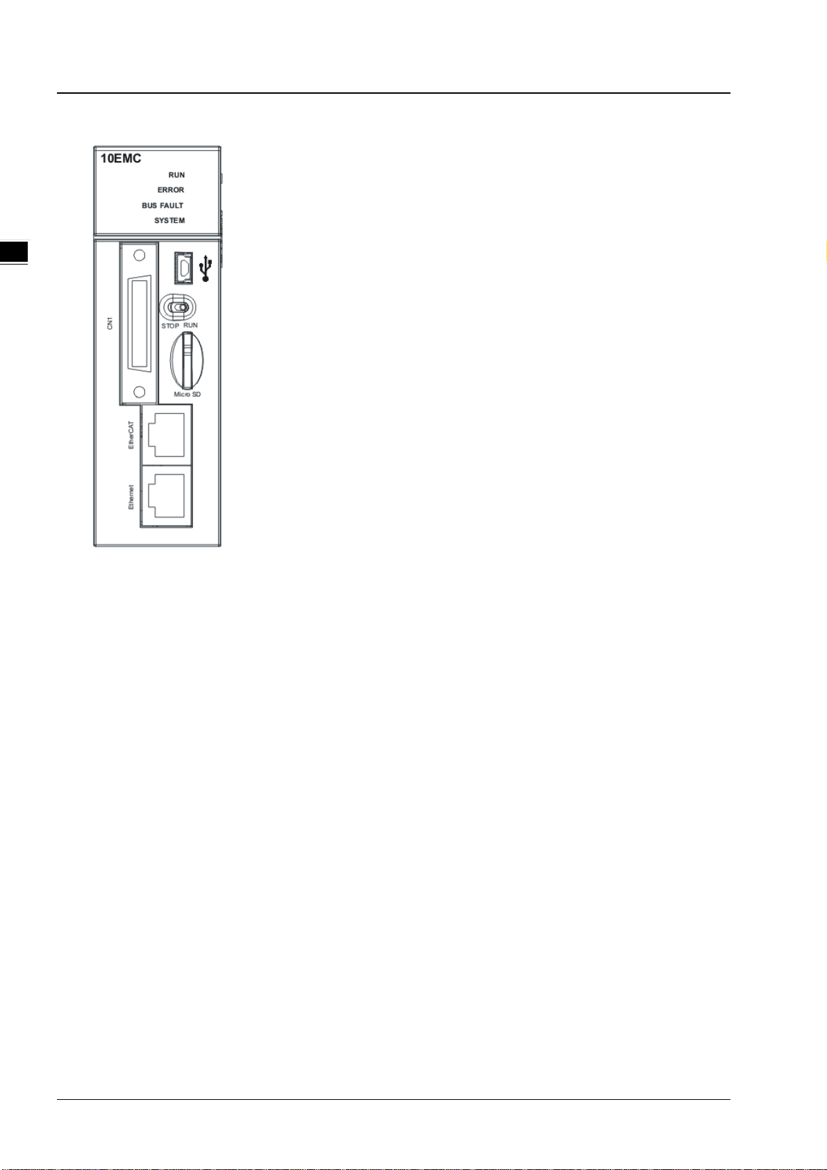
3.2.5 Profiles
AHxxEMC-5A
2
RUN LED
indicator
3-14
Operating status of the CPU module
ON: The user program is being executed.
OFF: The execution of the user program s tops.
Page 46

3_
Number
Name
Description
ERROR LED
Blink: A slight error occurs in the system.
Blink: A slight error occurs in the I/O bus.
Blink: The CPU module is being reset / The value in the device is being cleared.
3
Mini USB port
Providing the RS-232 communicat ion interface
STOP: The execution of the user program st ops .
5
SD slot
Micro SD interface
6
Connector
Connecting the module and an I/O extension cable.
7
EtherCAT port
Providing the EtherCAT communication i nterface
8
Ethernet port
Providing the Ethernet communication interface
9
Set screw
Fixing the module
11
Hook
Connecting the module and a backplan e.
RUN
ETH
ERROR
RUN
Ethernet
EtherCAT
CN1
RUN
STOP
Micro SD
EtherCAT
10EMC
ETH
ERROR
indicator
BUS FAULT LED
indicator
SYSTEM LED
indicator
Chapter 3 Product Specifications
Error status of the CPU module
ON: A serious error occurs in the system.
OFF: The system is normal.
Error status of the I/O bus
ON: A serious error occurs in the I/O bus.
OFF: The I/O bus is normal.
System status of the CPU module
ON: The external input/output is forced ON/OFF.
OFF: The system is in a default status.
4 RUN/STOP switch
10 Label Nameplate
3.2.6 Dimensions
RUN: The user program is executed.
Dimensions are in mm.
3-15
Page 47

AH Motion Controller – Hardware Manual
_3
Function
Function
Pulse
Count
Pulse
Count
1
COM COM
19
Y0.11 Out3
3
COM COM
21
Y0.9 Out1
4
COM COM
22
Y0.8 Out0
6
X1.5 Rst5
24
X1.2 CntA5
7
S/S S/S
25
X1.1 CntA4
8
X1.4 Rst4
26
X1.0 CntA4
9
S/S S/S
27
X0.15
CntA3
10
X0.3 Rst3
28
X0.14
CntA3
11
S/S S/S
29
X0.13
CntA2
13
X0.1- Rst1-
31
X0.1+
Rst1+
14
X0.11-
CntB1-
32
X0.11+
CntB1+
16
X0.0- Rst0-
34
X0.0+ Rst0+
17
X0.9-
MPGB-
CntB0-
35
X0.9+
MPGA-
CntB0+
SD
MiniSD
MicroS
3.2.7 Arrangement of Terminals
AHxxEMC-5A
Pin Terminal
2 COM COM 20 Y0.10 Out2
5 S/S S/S 23 X1.3 CntA5
12 X0.2 Rst2 30 X0.12
DOG5-
15 X0.10-
DOG4-
CntA1- 33 X0.10+
Pin Terminal
DOG3
DOG2
DOG1
DOG0
DOG5+
DOG4+
CntA2
CntA1+
18 X0.8- MPGB+ CntA0- 36 X0.8+ MPGA+ CntA0+
3.2.8 Memory Card Slot
AHxxEMC-5A
The AH Motion seri es CPU modules support micro SD cards. You can purchase products which meet the specifications
supported by the memory card slot on the AH Motion CPU.
SD Cards
SD cards have three size types: SD cards, miniSD cards, and microSD cards. The AH Motion CPU supports Micro SDHC
cards.
3-16
Page 48

Chapter 3 Product Specifications
3_
Type
SD
SDHC
SDXC
Capacity
32 GB max.
system
2
Size
SD
SDHC
MiniSDHC
MicroSDHC
SDXC
MicroSDXC
Class 10 (Min. 10 MB/sec.)
Specifications for Memory Cards
The specifications of SD c ards can also be classified into three types according to capacity: SD cards, SDHC cards, and
SDXC cards. The AH Motion CPU supports MicroSDHC in FAT32 file system as below. Be sure to purchase pr oducts
which meet the specifications.
SD card families
File
Speed
class
rating
2 GB Max.
FAT/FAT3
N/A
FAT16/FAT32
Class 2 (Min. 2 MB/sec.)
Class 4 (Min. 4 MB/sec.)
Class 6 (Min. 6 MB/sec.)
32 GB~2 TB
exFAT
Class 2 (Min. 2 MB/sec.)
Class 4 (Min. 4 MB/sec.)
Class 6 (Min. 6 MB/sec.) Class 10 (Min.
10 MB/sec.)
3.3 I/O Modules
AH motion controller PLC supports the following I/O module types: digital input/output modules, analog input/output
modules, temperature measurement modules, network modules, motion control modules, r emote I/O modules. Refer to
Chapter 3 of the AH500 Hardware Manual for more details.
3-17
Page 49

AH Motion Controller – Hardware Manual
_3
MEMO
3-18
Page 50

4
Chapter 4 Installation and Wiring
Table of Contents
4.1 Quick Review before Installation ................................................................ 4-2
4.1.1 AH Motion Hardware Components ............................................................... 4-2
4.2 Points to Note on Installation ..................................................................... 4-6
4.3 Installation ................................................................................................. 4-7
4.3.1 CPU Rack Installation in a Control Panel ....................................................... 4-7
4.3.2 Mounting a Backplane ............................................................................... 4-7
4.3.3 Installing a Module .................................................................................... 4-9
4.3.4 Installing a Removable Terminal Block ....................................................... 4-10
4.3.5 Installing an External Terminal Module ....................................................... 4-14
4.3.6 Connecting Communication Cables ............................................................ 4-15
4.3.7 Installing and Removing a Memory Card .................................................... 4-15
4.4 Points to Note about Wiring ..................................................................... 4-16
4.5 Wiring Power Supply Modules .................................................................. 4-18
4.5.1 Precautions ............................................................................................ 4-18
4.5.2 Ground .................................................................................................. 4-19
4.5.3 Wiring Power Supply Modules ................................................................... 4-20
4.5.4 Power Consumption ................................................................................ 4-23
4.6 Wiring AH Motion CPU Modules ................................................................ 4-24
4.6.1 Specifications of Inputs and Outputs .......................................................... 4-24
4.6.2 Wiring AHxxEMC-5A ................................................................................ 4-27
4.7 Wiring I/O Modules .................................................................................. 4-31
4-1
Page 51

Chapter 4 Installation and Wiring
_
4.1 Quick Review before Installation
Before you start the installation and wiring of AH Motion system, we suggest that you review your actual application and
have a clear idea of the required components in your system. This section will give you a quick overview of the
components in AH Motion CPU rack configuration. You can also refer to CH2 System Configuration for planning the
system or CH3 Product Specifications for choosing proper products for your system.
4.1.1 AH Motion Hardware Components
A complete AH Motion CPU rack consists of a Motion backplane, a power supply module, a Motion CPU module, and
additional AH500 series I/O modules as below.
Powre supply module
AH Motion backplane
AH Motion CPU
10EMC
BUS FAULT
CN1
Ethernet EtherCAT
ERROR
SYSTEM
RUN
RUNSTOP
Micro SD
06XA 10SCM
ERROR
RUN
AH500 series modules
10DNET
RUN
ERROR
COM1 RS485
COM2 RS485
TR1
ON
OFF
COM1
TX+
TX-
RX+
D+
RX-
D-
GNDGND
FG
FG
TR2
OFF
ON
COM2
TX+
TX-
D+
RX+
D-
RX-
GND
GND
FG
FG
Node Address
4
3
2
4
3
2
10COPM
MS
NS
5
6
7
1
x10
8
9
1
0
5
Node Address
6
7
0
x10
8
9
1
0
DR 1
DR 0
IN 1
IN 0
ERROR
16AN01T
RUN
312
0
5
124910
118
15147613
1
x16
0
x16
DR 2
DR 1
DR 0
IN 0
CAN+
SHLD
CAN-
GND
AH Motion backplane
Basic Components
An AH Motion CPU rack consists of the following four basic components.
- Motion backplane
A Motion CPU module and other modules are installed on a Motion backplane which functions as the
communication interface between CPU and modules. The Motion backplane also provides an additional COM port
(RS-485).
4
AHBP05M2-5A: supporting up to 5 additional I/O modules
4-2
Page 52

Chapter 4 Installation and Wiring
_
- Power supply modules
A power supply module functions to convert alternating current to direct current, or directly provides direct current.
It provides power for the modules installed on it. A Motion backplane must `be assigned a power supply module. A
power supply module has to be installed on the left-most side of a backplane.
AHPS05-5A AHPS15-5A
PS05
PS15
POW ER
- Motion CPU module
A Motion CPU module is the core of a complete AH Motion system. It is responsible for controlling and managing
the whole system, and is installed in the second slot from the left on the Motion backplane.
AHxxEMC-5A
10EMC
RUN
RUN
ERROR
ERROR
EtherCAT
CN1
Ethernet EtherCAT
ETH
ETH
RUNSTOP
Micro SD
- Communication cables
Several communication interfaces are built in a Motion CPU module. You can select a suitable communication
cable according to the required application.
4
Refer to the following table for information about the communication interfaces and the main applications.
Interface Connector Application
EtherCAT RJ45 Industrial network connecting EtherCAT slaves
EtherNet RJ45
Computer/HMI communication/remote control/data exchange/industrial
network
RS-232 Mini USB Programming
RS-485 Terminal block Programming
4-3
Page 53

AH Motion Controller – Hardware Manual
_
Additional Modules
In addition to the basic components, you can also expand the function by attaching I/O modules or function modules.
The following are the applicable modules for an AH Motion CPU rack. You can select the proper products according to
your needs.
- Motion control modules:
4
AH02HC-5A
AH04HC-5A
AH05PM-5A
AH10PM-5A
AH15PM-5A
AH20MC-5A
- Digital input/output modules:
AH16AM10N-5A
AH32AM10N-5A
AH32AM10N-5B
AH32AM10N-5C
AH64AM10N-5C
AH16AM30N-5A
AH16AN01R-5A
AH16AN01T-5A
AH16AN01P-5A
Two-channel high-speed counter module (200 kHz)
Four-channel high-speed counter module (200 kHz)
Two-axis pulse train motion control module (1 MHz)
Six-axis pulse train motion control module
(Four axes: 1 MHz; Two axes: 200 kHz)
Four-axis pulse train motion control module (1 MHz )
Twelve-axis DMCNET (Delta Motion Control Network) motion control module (10 Mbps)
24 VDC, 5 mA, 16 inputs, Terminal block
24 VDC, 5 mA, 32 inputs, Terminal block
24 VDC, 5 mA, 32 inputs, DB37 connector
24 VDC, 5 mA, 32 inputs, MIL connector
24 VDC, 3.2 mA, 64 inputs, MIL connector
100~240 VAC, 4.5 mA/9 mA (100 V, 50 Hz), 16 inputs, Terminal block
240 VAC/24 VDC, 2 A, 16 outputs, Relay, Terminal block
12~24 VDC, 0.5 A ,16 outputs, Sinking output(NPN), Terminal block
12~24 VDC, 0.5 A, 16 outputs, Sourcing output(PNP), Terminal block
AH16AN01S-5A
AH32AN02T-5A
AH32AN02T-5B
AH32AN02T-5C
AH32AN02P-5A
AH32AN02P-5B
AH32AN02P-5C
AH64AN02T-5C
AH64AN02P-5C
AH16AP11R-5A
AH16AP11T-5A
AH16AP11P-5A
110/220 VAC, 0.5 A, 16 outputs, TRIAC, Terminal block
12~24 VDC, 0.1 A, 32 outputs, Sinking output(NPN), Terminal block
12~24 VDC, 0.1 A, 32 outputs, Sinking output(NPN), DB37 connector
12~24 VDC, 0.1 A, 32 outputs, Sinking output(NPN), MIL connector
12~24 VDC, 0.1 A, 32 outputs, Sourcing output(PNP), Terminal block
12~24 VDC, 0.1 A, 32 outputs, Sourcing output(PNP), DB37 connector
12~24 VDC, 0.1 A, 32 outputs, Sourcing output(PNP), MIL connector
12~24 VDC, 0.1 A, 64 outputs, Sinking output(NPN), MIL connector
12~24 VDC, 0.1 A, 64 outputs, Sourcing output(PNP), MIL connector
24 VDC, 5 mA, 8 inputs ,240 VAC/24 VDC, 2 A, 8 outputs, Relay ,Terminal block
24 VDC, 5 mA, 8 inputs, 12~24 VDC, 0.5 A, 8 output, Sinking output(NPN), Terminal
block
24 VDC, 5 mA, 8 inputs, 12~24 VDC, 0.5 A, 8 outputs, Sourcing output(PNP), Terminal
block
4-4
Page 54

_
- Analog input/output modules:
Four-channel analog input module
AH04AD-5A
AH08AD-5A
AH08AD-5B
AH08AD-5C
AH04DA-5A
AH08DA-5A
16-bit resolution
-10~+10 V, 0~10 V, -5~+5 V, 0/1~5 V, 0/4~20 mA, or -20~+20 mA
Eight-channel analog input module
16-bit resolution
-10~+10 V, 0~10 V, -5~+5 V, 0/1~5 V, 0/4~20 mA, or -20~+20 mA
Eight-channel analog input module
16-bit resolution
-10~+10 V, 0~10 V, -5~+5 V, 0/1~5 V
Eight-channel analog input module
16-bit resolution
0/4~20 mA or -20~+20 mA
Four-channel analog output module
16-bit resolution
-10~+10 V, 0~10 V, -5~+5 V, 0/1~5 V, or 0/4~20 mA
Eight-channel analog output module
16-bit resolution
-10~+10 V, 0~10 V, -5~+5 V, 0/1~5 V, or 0/4~20 mA
Chapter 4 Installation and Wiring
4
Eight-channel analog output module
AH08DA-5B
AH08DA-5C
AH06XA-5A
- Temperature measurement modules:
AH04PT-5A
AH08PTG-5A
AH04TC-5A
AH08TC-5A
16-bit resolution
-10~+10 V, 0~10 V, -5~+5 V, or 0/1~5 V
Eight-channel analog output module
16-bit resolution
0/4~20 mA
Four-channel analog input and two-channel analog output module
16-bit resolution
Analog input: -10~+10 V, 0~10 V, -5~+5 V, 0/1~5 V, 0/4~20 mA, or -20~+20 mA
Analog output: -10~+10 V, 0~10 V, -5~+5 V, 0/1~5 V, or 0/4~20 mA
Four-channel four-wire/three-wire RTD
Sensor type: Pt100, Pt1000, Ni100, Ni1000, or 0~300 Ω input impedance
Eight-channel four-wire/three-wire/two-wire RTD
Sensor type: Pt100, Pt1000, Ni100, Ni1000, or 0~300 Ω input impedance
Four-channel thermocouple
Sensor type: J, K, R, S, T, E, N, or -150~+150 mV
Eight-channel thermocouple
Sensor type: J, K, R, S, T, E, N, or -150~+150 mV
- Network modules:
AH10EN-5A
AH15EN-5A
AH10SCM-5A It is a serial communication module with two RS-485/RS-422 ports, and supports
It is an Ethernet communication module with two Ethernet ports, and supports Modbus
TCP protocols, and EtherNet/IP software (V2.0). It can function as a master or a slave.
It is an Ethernet communication module with two Ethernet ports, and supports Modbus
TCP protocols, and IEC60870-5-104. It can function as a master or a slave.
4-5
Page 55

AH Motion Controller – Hardware Manual
_
Modbus and UD Link protocols. One part of communication is isolated from the other
part of the communication, and one part of power is isolated from the other part of the
power.
It is a serial communication module with two RS-232 ports, and supports Modbus and
AH15SCM-5A
UD Link protocols. One part of communication is isolated from the other part of the
communication, and one part of power is isolated from the other part of the power.
4
AH10DNET-5A
AH10PFBM-5A It is a PROFIBUS communication module. It can function as a master.
AH10PFBS-5A It is a PROFIBUS communication module. It can function as a slave.
AH10COPM-5A It is a CANopen communication module. It can function as a master or a slave.
- Remote I/O module:
AHRTU-DNET-5A It is a DeviceNet remote I/O communication module.
AHRTU-PFBS-5A It is a PROFIBUS remote I/O communication module.
AHRTU-ETHN-5A It is an Ethernet remote I/O communication module.
- Dummy module:
AHASP01-5A
It is a DeviceNet communication module. It can function as a master or slave. A
maximum of 1Mbps per second can be transferred.
Dummy module used for an empty I/O slot
4.2 Points to Note on Installation
An AH Motion system only supports the horizontal installation, and a power supply module has to be installed on the
left-most side of a backplane.
Product dimensions (modules, backplanes, cables and more) should be confirmed when making an installation layout.
To obtain sufficient installation space, you should also save proper wiring space for connectors, cables and other
instruments.
Make sure that the work environment conforms to the specifications for the products. It is necessary to take account of
the basic temperature/humidity control and the dust/corrosion prevention.
The electromagnetic interference will result in the wrong action of the whole system. Therefore, you have to do EMC
design carefully. Refer to Appendices in this manual for more information related to EMC standards.
If the specifications for the components such as screws and washers are noted specifically in the manual, use the
components conforming to the specifications.
If a cable is connected to a communication port, make sure that the connector of the cable is joined to the port on the
module properly.
A backplane has to be mounted on a plane stably instead of being just set on the plane. After it is installed, make sure
that it is fixed on the plane.
4-6
Page 56

Chapter 4 Installation and Wiring
_
4.3 Installation
4.3.1 CPU Rack Installation in a Control Panel
The motion controller has to be installed in a closed control box. In order to ensure that the PLC disapates heat properly,
the space between the motion controller and the control box has to be larger than 50 millimeters.
50mm>
10EMC 06XA 10SCM 10DNET 10COPM 16AN01T
50mm>
50mm>
50mm>
Keep the motion controller away from high-voltage equipment, high-voltage wires, and high-voltage motors.
In order to prevent the temperature of a motion controller from rising, do not install the motion controller vertically on
the bottom/top in the control box.
Install a motion controller horizontally in the control box, as shown above.
If you intend to increase the number of modules, you have to leave some space for installing the modules in the control
box.
4.3.2 Mounting a Backplane
Fixing a backplane by screws
Mount the backplane on a plane by means of M5 screws, as illustrated below. To fix the backplane, you need to
evaluate the length of a screw, the size of a thread, and whether to use a nut according to the actual condition of the
plane unless there are specific specifications for a screw which are indicated in the pictures below.
1. Tighten the M5 screws in the holes indicated by a.
a
a
4
4-7
Page 57

AH Motion Controller – Hardware Manual
_
2. Tighten the two screws in the holes indicated by b.
4
b
Installing a DIN rail
1. The installation is applicable to a 35 millimeter DIN rail.
2. Install the mounting clips on a backplane.
3. Install the backplane on a DIN rail.
b
Step 1: Press the hook in the direction indicated by the arrow.
Step 2: Mount the DIN rail clips onto a DIN rail.
Step 3: Pull the hook to fix the clips and the DIN rail.
1
2
DIN rail
3
4-8
Page 58

_
Removing a DIN rail
Step 1: Press the hook in the direction indicated by the arrow.
Step 2: Remove the backplane.
1
Chapter 4 Installation and Wiring
DIN rail
2
4.3.3 Installing a Module
Insert a module into a slot, make sure that the module is installed on the backplane properly, and tighen the the screw, as
illustrated below.
1. Insert the hook under the module into the hole in the backplane.
2. Push the module in the direction indicated by the arrow until it clicks.
4
4-9
Page 59

AH Motion Controller – Hardware Manual
_
3. Tighten the screw on the module.
4
4.3.4 Installing a Removable Terminal Block
Installation
1. Align a terminal block with the printed circuit board, and press it into the module.
Type 1
4-10
Page 60

_
Type 2
Chapter 4 Installation and Wiring
2. Press the clip in the direction indicated by the arrow. For high-definition terminals(Type 2), a flat head screw driver
is required to fasten the screws on both ends.
Type 1
Type 2
4
Removal
1. Pull the clip in the direction indicated by the arrow. For high-definition terminals(Type 2), a flat head screw driver is
required to loose the screws on both ends.
4-11
Page 61

AH Motion Controller – Hardware Manual
_
Type 1
4
Type 2
2.
2. Pull up the clip. High-definition terminals(Type 2) can be pull out directly.
Type 1
4-12
Page 62

_
Type 2
3. The terminal block is removed.
Chapter 4 Installation and Wiring
Type 1 Type 2
4
4-13
Page 63

AH Motion Controller – Hardware Manual
_
4.3.5 Installing an External Terminal Module
Installation
1. One side of an external terminal module has to be fixed first.
2. Press the terminal module in the direction indicated by arrow 1, and make sure that the groove is combined with
the DIN rail.
4
Removal
1. Push the terminal module in the direction indicated by arrow 1.
2. Pull the terminal module in the direction indicated by arrow 2.
4-14
Page 64

Chapter 4 Installation and Wiring
_
4.3.6 Connecting Communication Cables
Plug a communication cable in the port on a Motion CPU module, and make sure that the connector of the cable is joined
to the port properly. RS-232 (USB), RS-485 (terminals on the backplane), CN1 and RJ45 cables could be used.
4.3.7 Installing and Removing a Memory Card
4
Formatting of a Memory Card
A memory card needs to be formatted before the first use on an AH Motion CPU module. Make sure the file system
you use on formatting the SD card is FAT32.
SD Slot on a Motion CPU
As shown below, the SD slot is in the middle of the front of a Motion CPU module.
SD slot
4-15
Page 65

AH Motion Controller – Hardware Manual
_
Installing a Memory Card
Insert a memory card into the SD slot in a Motion CPU module, and push it downward until it clicks. After the memory
card is installed, it is fixed firmly in the slot. If the memory card is loose, it is not installed correctly. Besides, the
memory card has mistake-proofing design. If it is inserted in the wrong direction, it can not be pushed downward. This
is to prevent the CPU module from being damaged. The correct way to insert the memory card is shown below.
4
Removing a Memory Card
After a memory card is pushed downward, it springs from the slot, and you can take it out.
4.4 Points to Note about Wiring
Points for attention
Before installing or wiring a module, you need to make sure that the external power supply is turned
DANGER
off. If the power supply is not turned off, you may get an electric shock, or the product may be
damaged.
If the installation of the module or the wiring of the module is complete, you need to make sure that a
terminal block cover is installed on the module before you turn on the power supply or operate the
module. If the terminal block cover is not installed properly, you may get an electric shock, or the
module may not operate normally.
4-16
Be sure to connect the terminals FG and LG with protective grounding conductors. Otherwise, users
may get an electric shock, or the module may not operate normally.
To ensure that a PLC is wired correctly, users need to check the rated voltage of the product, and the
arrangement of the terminals. If the PLC is connected to the power supply which does not conform
to the rated voltage, or the product is not wired correctly, a fire accident will occur, or the product will
Page 66

Chapter 4 Installation and Wiring
_
y
be damaged.
The external connections should be crimped or press-welded by specific tools, or soldered correctly.
The improper connections will result in a short circuit, a fire accident, or erroneous operation.
Tighten the terminal screws with the specified torque. If the terminal screws are loose, a short circuit,
a fire accident, or erroneous operation will occur. Tightening the terminal screws too far, may cause
damage to the terminal screws and the module, resulting in a short circuit or a malfunction.
Make sure that there are no foreign substances such as iron filings or wiring debris inside the
module. Theses foreign substances may result in a fire accident, damage, or erroneous operation.
Wiring an I/O module
(1) Definition of 2/3/4-wire connection:
- 2/3-wire connection(passive sensors): share the power circuit with the system
- 4-wire connection(active sensors): independently powered. Not recommended to share the same power circuit
with the system
(2) Terminals with insulation sleeves can not be arranged as a terminal block. It is recommended that the terminals
be covered with insulation tubes.
(3) Please use single-core cables or twin-core cables. The diameters of the cables used should be in the range of 12
AWG to 22 AWG. The torques applied to the screw terminals should be in the range of 5 kg-cm (4.3 Ib-in) to 8
kg-cm (6.9 Ib-in). Please use copper conducting wires. The temperature of the copper conducting wires should
be 60/75°C.
4
(4) Please keep the input cables, the output cables, and the power cable separate form one another.
(5) If the main circuit and the power cable can not be separated from each other, please use a shielded cable, and
ground it at the side of the I/O module. In some cases, the shielded cable is grounded at the opposite side.
Shilded cable
Load through which the
alternating current passes
AC power
suppl
(6) If you wire a module by means of piping, you need to ground the piping correctly.
(7) Please keep 24 VDC input cables separate from 110 VAC input cables and 220VDC input cables.
(8) If the wiring length is more than 200 meters (686.67 inches), the leakage current will result from parasitic
capacitance, and the system will break down.
Grounding a cable
Please ground a cable according to the steps below.
(1) Please ground a cable correctly.
2
(2) The area of the cross-section of the cable which is grounded should be 2 mm
(3) The ground point should be near the PLC. Ground the cable properly.
or larger than 2 mm2.
4-17
Page 67

AH Motion Controller – Hardware Manual
_
f
Note
(1) The 110 V/220 V power cable and the 24 VDC power cable should be thick cables. (The area of the
cross-section of the cable is 2 mm
at terminal screws. To prevent the short circuit which results from loose screws, you need to use solderless
terminals with insulation sleeves.
2
, and the diameter of the cable is 14 AWG.) Be sure to twist the power cables
(2) If cables are connected to the terminals LG and FG, the cables need to be grounded. Do not connect LG and FG
to any devices. If LG and FG are not grounded, the PLC will be susceptible to noise. Since LG have potential,
you will get an electric shock if you touch metal parts.
4.5 Wiring Power Supply Modules
4.5.1 Precautions
Connecting AC power cables
(1) Please separate the power cable of AHPS05-5A from the power cables for I/O devices and other devices. If there
is much noise, connect an isolating transformer.
Isolating trans
ormer
AHPS05-5A
4
AC power supply
100-240 V
I/O equipment
Another piece of equipment
(2) The 110 VAC cable, the 220 VAC cable, and the 24 VDC cable should be twisted, and connected to a module
within a short distance.
(3) Do not bundle 110 VAC cable, the 220 VAC cable, the 24 VDC cable, the (high-voltage high-current) main circuit,
and the I/O signal cable together. Besides, it is recommended that the distance between adjacent cables should
be more than 100 millimeters.
(4) To prevent the surge resulting from lightning, please install a surge absorber in the way shown below.
Surge absorber
AC power supply
AHPS05-5A
I/O equipment
100-240V
Points for attention:
1. The surge absorber and the PLC system should be grounded separately.
2. Please select the surge absorber whose working voltage is not less than the maximum allowable input voltage.
Connecting DC power cables
(1) AHPS15-5A is independently supplied with power by a DC power supply. Please separate the power cable of the
DC power supply from the power cables for I/O devices and other devices. If there is much noise, connect an
isolating transformer.
4-18
Page 68

Chapter 4 Installation and Wiring
_
Isolating transformer
DC
24 V DC
AHPS15-5A
I/O equipment
Another piece of equipment
AC power supply
100-240 V
powe r
supply
(2) The 110 VAC cable, the 220 VAC cable, and the 24 VDC cable should be twisted, and connected to a module
within a short distance.
(3) Do not bundle 110 VAC cable, the 220 VAC cable, the 24 VDC cable, the (high-voltage high-current) main circuit,
and the I/O signal cable together. Besides, it is recommended that the distance between adjacent cables should
be more than 100 millimeters.
(4) To prevent the surge resulting from lightning, please install a surge absorber in the way shown below.
Surge absorber
AC power supply
100-240V
DC po w er s uppl y
I/O equipment
Another piece of equipment
Points for attention:
1. The surge absorber and the PLC system should be grounded separately.
2. Please select the surge absorber whose working voltage is not less than the maximum allowable input voltage.
4.5.2 Ground
The diameter of the ground should not be less than the
diameters of the cables connected to the terminals L and N.
If much equipment is used, please use single-point ground.
If single-point ground can not be used, please use
common-point ground.
AHPS05-5A
AHPS15-5A
The single-point ground is better.
AHPS05-5A
AHPS15-5A
Another piece of
equipment
Another piece of
equipment
4
you can not ground equipment in the way shown on
the right.
The common-point ground is permitted.
AHPS05-5A
AHPS15-5A
An other piece of
equipment
The equipment can not be grounded in this way.
4-19
Page 69

AH Motion Controller – Hardware Manual
_
4.5.3 Wiring Power Supply Modules
Connecting an AC power cable
4
*1. 24V on the external power supply is connected to VS+ and VS- on the power supply module. VS+ and VS- can be
used to detect whether the voltage of the external power supply is stable.
*2. FG on the power supply module is connected to the control box as the functional ground.
*3. The live wire and the neutral wire in the AC power cable are connected to L and N on the power supply module
respectively. To prevent the system from becoming abnormal, the ground in the AC power cable has to be
connected to LG on the power supply module.
The power input of AHPS05-5A is the AC input. You have to pay attention to the following points when you use
AHPS05-5A.
The alternating-current input voltage is in the range of 100 VAC to 240 VAC. Please connect the power supply to
the terminals L and N. If the 110 VAC or the 220 VAC power supply is connected to the input terminals VS+ and
VS-, the PLC will be damaged.
In order to ensure that the external power supply stably provides24 VDC power, the external power supply can be
connected to VS+ and VS-. If the PLC detects that the voltage of the external power supply is lower than the
working voltage, you can write a protective program.
The length of the cable connecting with the ground should be more than 1.6 millimeters.
If the power cut lasts for less than 10 milliseconds, the PLC keeps running without being affected. If the power cut
lasts for long, or if the voltage of the power supply decreases, the PLC stops running, and there is no output. When
the power supply returns to normal, the PLC resumes. (You have to notice that there are latched auxiliary relays
and registers in the PLC when you write the program.)
Please use single-core cables or multicore cables. The diameters of the cables used should be in the range of 12
AWG to 22 AWG. The torque applied to the terminal screws should be 9.50 kg-cm (8.25 Ib-in). Please use copper
conducting wires. The temperature of the copper conductive cables should be 60/75°C.
4-20
Page 70

Chapter 4 Installation and Wiring
_
Safety wiring: The PLC controls many devices, and the activity of any device affects the activity of other devices. If
any device breaks down, the whole automatic control system goes out of control, and the danger occurs. The
protection circuit is shown below.
MC
100~240VAC
50/60Hz
VS+
VS-
UP
ZP
24VDC
UP
ZP
PS05 CPU
2A
L
N
VS+
PS05
2A
L
N
①
Alternating-current power supply: 100~240 VAC, and 50/60 Hz
VS-
24VDC
UP
AI/AO
ZP
DI/DO AI/AO
m duleo
Network Motion
m duleom duleo
m duleo
m duleo
4
②
Circuit breaker
Emergency stop: The emergency stop button can be used to cut off the power when an emergency
③
occurs.
④
Power indicator
⑤
Load through which the alternating current passes
⑥
2 A fuse
⑦
The ground impedance is less than 100 Ω.
○8
Direct-current power supply: 24 VDC
4-21
Page 71

AH Motion Controller – Hardware Manual
_
Connecting a DC power cable
4
*1. 24V on the external power supply is connected to VS+ and VS- on the power supply module. VS+ and VS- can be
used to detect whether the voltage of the external power supply is stable.
*2. FG on the power supply module is connected to the control box as the functional ground.
*3. +24V and 24G on the power supply module are connected to 24V and 0V on the DC power supply. To prevent the
system from becoming abnormal, the ground of the DC power supply has to be connected to FE on the power
supply module.
The power input of AHPS15-5A is the DC input. You have to pay attention to the following points when you use
AHPS15-5A.
In order to ensure that the external power supply stably provides 24 VDC power, the external power supply can be
connected to VS+ and VS-. If the PLC detects that the voltage of the external power supply is lower than the
working voltage, you can write a protective program.
The length of the cable connecting with the ground should be more than 1.6 millimeters.
If the power cut lasts for less than 10 milliseconds, the PLC keeps running without being affected. If the power cut
lasts for long, or if the voltage of the power supply decreases, the PLC stops running, and there is no output. When
the power supply returns to normal, the PLC resumes. (You have to notice that there are latched auxiliary relays
and registers in the PLC when you write the program.)
Please use single-core cables or multicore cables. The diameters of the cables used should be in the range of 12
AWG to 22 AWG. The torque applied to the terminal screws should be 9.50 kg-cm (8.25 Ib-in). Please use copper
conducting wires. The temperature of the copper conductive cables should be 60/75°C.
4-22
Page 72

_
4.5.4 Power Consumption
Products Model name Internal power consumption External power consumption
Chapter 4 Installation and Wiring
AH Motion CPU
Motion control
backplane
Motion control module
AHxxEMC-5A 4 W -
AHBP03M2-5A 1.2 W -
AHBP05M2-5A 1.2 W
AH02HC-5A 2.4 W -
AH04HC-5A 2.4 W -
AH05PM-5A 2.7 W -
AH10PM-5A 2.7 W -
AH15PM-5A 2.7 W -
AH20MC-5A 3 W -
AH16AM10N-5A 0.1 W 1.9 W
AH16AM30N-5A 0.1 W -
AH16AN01P-5A 0.2 W 0.4 W
AH16AN01R-5A 2.1 W -
AH16AN01S-5A 0.6 W -
AH16AN01T-5A 0.2 W 0.4 W
AH16AP11P-5A 0.2 W 0.2 W
AH16AP11R-5A 1.1 W -
4
Digital I/O module
Analog I/O module
AH16AP11T-5A 0.2 W 0.2 W
AH32AM10N-5A 0.2 W 3.8 W
AH32AM10N-5B 0.2 W 3.8 W
AH32AM10N-5C 0.2 W 3.8 W
AH32AN02P-5A 0.4 W 0.8 W
AH32AN02P-5B 0.4 W 0.8 W
AH32AN02P-5C 0.4 W 0.8 W
AH32AN02T-5A 0.4 W 0.8 W
AH32AN02T-5B 0.4 W 0.8 W
AH32AN02T-5C 0.4 W 0.8 W
AH64AM10N-5C 0.2 W 4.9 W
AH64AN02P-5C 0.6 W 1.5 W
AH64AN02T-5C 0.6 W 1.5 W
AH04AD-5A 0.35 W 1 W
AH04DA-5A 0.34 W 2.6 W
AH06XA-5A 0.34 W 1.4 W
AH08AD-5A 1.1W -
AH08DA-5A 0.36W 4.55W
AH08AD-5B 1.9 W -
4-23
Page 73

AH Motion Controller – Hardware Manual
_
Products Model name Internal power consumption External power consumption
AH08DA-5B 0.25 W 2.2 W
AH08AD-5C 1.6 W -
AH08DA-5C 0.25 W 3.7 W
AH04PT-5A 2 W -
4
Temperature
measurement module
Network module
Remote I/O module
AH08PTG-5A 0.7W 4W
AH04TC-5A 1.5 W -
AH08TC-5A 1.5 W -
AH10EN-5A 1.6 W -
AH15EN-5A 1.6 W -
AH10SCM-5A 1.2 W -
AH15SCM-5A 1.2 W -
AH10DNET-5A 0.9 W 0.72 W
AH10PFBS-5A 1 W -
AH10PFBM-5A 2 W -
AH10COPM-5A 0.8 W -
AHRTU-DNET-5A 0.75 W 0.72 W
AHRTU-PFBS-5A 2 W -
AHRTU-ETHN-5A 2.16 W -
4.6 Wiring AH Motion CPU Modules
4.6.1 Specifications of Inputs and Outputs
AHxxEMC-5A
Execution
Input/Output control
Programming language
Instruction execution speed
Constant scan cycle (ms)
Program capacity (step)
Installation
General Specifications
AHxxEMC-5A Remark
The program is executed cyclically.
The inputs and outputs can be
Cyclically refreshed inputs/outputs
Direct inputs/outputs
IEC 61131-3
Ladder diagram (LD), continuous function
chart (CFC), structured text (ST), and
sequential function chart (SFC).
0.3 ms/K steps
1-32000
(The scan cycle can be increased by one
millisecond.)
256K steps
DIN rails or screws
controlled through the direct inputs
(DX device) and direct outputs (DY
device).
The scan cycle time can be
specified by parameters.
4-24
Page 74

Chapter 4 Installation and Wiring
_
General Specifications
AHxxEMC-5A Remark
Installation of modules
Number of modules
Number of tasks
Number of input/output
devices
Number of inputs/outputs
Input relay [X]
Output relay [Y]
Auxiliary relay [M]
Timer [T]
Counter [C]
32-bit counter [HC/AC]
Modules are installed directly on a
backplane.
Five input/output modules at most can be
installed on a motion backplane.
283 tasks (32 cyclic tasks; 32 I/O interrupts;
212 external interrupts; 1 24V LV detection)
X/Y devices (bit): 8192
(X0.0~X511.15/Y0.0~Y511.15)
X/Y devices (word): 512
(X0~X511/Y0~Y511)
328 inputs/ 324 outputs (AH10EMC)
8192 (X0.0~X511.15)
8192 (Y0.0~Y511.15)
8192 (M0~M8191)
2048 (T0~T2047)
2048 (C0~C2047)
HC: 64 (HC0~HC63)
AC: 56 (AC0~ AC55) (AHxxEMC)
Number of devices which can be
used in a program
Number of inputs/outputs
accessible to an CPU
4
Data register [D]
Stepping relay [S]
Index register [E]
Special auxiliary relay [SM]
Special data register [SR]
Serial communication port
Ethernet port
USB port
Memory card slot
Real-time clock
D device (bit): 1048576 (D0.0~D65535.15)
D device (word): 65536 (D0~D65535)
2048 (S0~S2047)
32 (E0~E31)
SM: 2048 (SM0~SM2047)
SR: 2048 (SR0~SR2047)
One RS-232(USB), One RS-485
communication port
10/100 M
Mini USB
Supports Micro SD card (SD 2.0)
Years, months, days, hours, minutes,
seconds, and weeks
The function is available when the
CPU is used together with the
motion backplane
4-25
Page 75

AH Motion Controller – Hardware Manual
_
Description of the terminals
4
Terminal Description
1. Differential input terminals.
2. The functions of the terminals:
High-speed count:
The terminals are the RESET input
X0.0+, X0.0-,
X0.1+, X0.1-
1. Common input terminals.
2. The functions of the terminals:
High-speed count:
X0.2, X0.3,
X1.4, X1.5
High-speed capture: The terminals can function
terminals for counter 0~counter 1.
X0.0+ and X0.0- are for counter 0.
X0.1+ and X0.1- are for counter 1.
High-speed capture: The terminals can
function as trigger signals for high-speed
captures.
The terminals are the RESET input
terminals for counter 2~counter 5.
X0.2 is for counter 2.
X0.3 is for counter 3.
X1.4 is for counter 4
X1.5 is for counter 5
as trigger signals for high-speed captures.
Response
characteristic
1MHz +/-5mA +/-5V
100kHz(*1) 5mA 24V
Rated input
Current Voltage
X0.8+, X0.8-,
X0.9+, X0.9-
X0.10+, X0.10-,
X0.11+, X0.11-
X0.12,
X0.13,
X0.14,
X0.15,
X1.0,
X1.1,
1. Differential input terminals.
2. The functions of the terminals:
Motion control: The terminals are for a manual
pulse generator.
High-speed count:
The terminals are for counter 0.
X0.8+ and X0.8- are the A-phase inputs for
counter 0. X0.9+ and X0.9- are the B-phase
inputs for counter 0.
High-speed capture: The terminals can function
as trigger signals for high-speed captures.
Interrupt inputs
1. Differential input terminals.
2. The functions of the terminals:
High-speed count:
The terminals are for counter 1.
X0.10+ and X0.10- are the A-phase inputs
for counter 1. X0.11+ and X0.11- are the
B-phase inputs for counter 1.
High-speed capture: The terminals can function
as trigger signals for high-speed captures.
Interrupt inputs
1. Common input terminals.
2. The functions of the terminals:
High-speed count:
The terminals are for counter 2~counter 5.
X0.12 and X0.13 are for counter 2.
X0.14 and X0.15 are for counter 3.
1MHz +/-5mA +/-5V
1MHz +/-5mA +/-5V
100kHz(*1) 5mA 24 V
4-26
Page 76

Chapter 4 Installation and Wiring
_
Terminal Description
X1.2,
X1.3
X1.0 and X1.1 are for counter 4.
X1.2 and X1.3 are for counter 5.
Response
characteristic
Rated input
Current Voltage
High-speed capture: The terminals can function
as trigger signals for high-speed captures.
Interrupt inputs:
X0.12, X0.13, X0.14 and X0.15 can function as
interrupt inputs.
Y0.8,
Y0.9,
Y0.10,
Y0.11
1. Pulse output temrinals (open collector).
2. The function of the terminals:
High-speed comparison: The terminals can
function as high-speed comparison outputs.
200 kHz 15 mA 24 V
*1. If the frequency of input signals received by an input terminal must be 200 kHz, the input terminal must be connected
to a 1 kΩ (2 W) resistor in parallel.
4.6.2 Wiring AHxxEMC-5A
External devices for AHxxEMC-5A
4
MDR36
connector
External
terminal
module
RJ45 (EtherCAT)
10EMC
CN1
E thernet Ethe rCA T
RUN
RUN
ERROR
ERROR
ETH
ETH
Ethe rCAT
USB
RUNSTOP
MicroSD
SD
Micro SD
RJ45 (Ethernet)
4-27
Page 77

AH Motion Controller – Hardware Manual
_
MDR36 connector
Pin Function Pin Function
4
1
2
3
4
5
6
7
8
9
10
11
12
13
14
15
16
17
COM 19 Y0.11
COM 20 Y0.10
COM 21 Y0.9
COM 22 Y0.8
S/S 23 X1.3
X1.5 24 X1.2
S/S 25 X1.1
X1.4 26 X1.0
S/S 27 X0.15
X0.3 28 X0.14
S/S 29 X0.13
X0.2 30 X0.12
X0.1- 31 X0.1+
X0.11- 32 X0.11+
X0.10- 33 X0.10+
X0.0- 34 X0.0+
X0.9- 35 X0.9+
18
USB port
Pin Function
1
2
3
4
5
EtherNet/IP port
Pin Signal Description
1
2
3
4
X0.8- 36 X0.8+
VBUS (4.4–5.25 V)
D−
D+
Ground
Ground
TX+
TX-
RX+
-- N/C
Transmitting data
(positive pole)
Transmitting data
(negative pole)
Receiving data
(positive pole)
4-28
5
6
-- N/C
RX- Receiving data
Page 78

_
(negative pole)
t
t
A
A
Chapter 4 Installation and Wiring
EtherCAT port
Pin Signal Description
7
8
1
2
3
4
5
6
7
8
-- N/C
-- N/C
TX+
TX-
RX+
-- N/C
-- N/C
RX-
-- N/C
-- N/C
Transmitting data
(positive pole)
Transmitting data
(negative pole)
Receiving data
(positive pole)
Receiving data
(negative pole)
4
Wiring the Differential Input Terminals
The direct-current signals in voltage 5 V can pass through the high-speed input terminals X0.0+~X0.1+, X0.0-~X0.1-,
X0.8+~X0.11+, and X0.8-~X0.11- on AHxxEMC-5A. The frequency of input signals can be up to 1 MHz. These
high-speed input terminals are connected to a differential (two-wire) line driver.
Wiring differential input terminals (The wiring below is used for high speed and high noise.)
Encoder outpu
AH04HC-5
high-speed inpu
A
A-
B
B-
Transistor Output Circuit
AHxxEMC-5A
LED
Trigger circuit
Y0.8
C0M
Load
< 0.5
Transistor output
4-29
Page 79

AH Motion Controller – Hardware Manual
_
COM COM C OM COM
4
Direct-current power supply
The output terminals of a transistor module are open-collector output terminals. If Y0.8 is a pulse train
output terminal of a transistor module, the output current passing through its output pull-up resistor must
be greater than 0.1 A to ensure that the transistor module operates normally.
A relay or a solenoid valve is used as a DC load. A diode is connected in parallel to absorb the surge
voltage which occurs when the load is OFF.
AHxxEMC-5A
Relay/ Solenoid valve
Y0.8
Emergency stop
+
D
COM
D: 1N4001 diode
A bulb (incandescent lamp) is used as a DC load. A thermistor is connected in series to absorb the surge
current which occurs when the load is ON.
AHxxEMC-5A
DC power supply
Fuse
4-30
COM
Y0.9 can not be connected to a power supply directly. It must be connected to a load.
AHxxEMC-5A
COM
Mutually exclusive output: For example, Y0.10 controls the clockwise rotation of the motor, and Y0.11
controls the counterclockwise rotation of the motor. The interlock circuit which is formed, and the program
in the PLC ensure that there are protective measures if an abnormal condition occurs.
Page 80

Chapter 4 Installation and Wiring
_
4.7 Wiring I/O Modules
AH motion controller PLC supports the following I/O module types: digital input/output modules, analog input/output
modules, temperature measurement modules, network modules, motion control modules, remote I/O modules. Refer to
Chapter 5 of the AH500 Hardware Manual for more details.
4
4-31
Page 81

AH Motion Controller – Hardware Manual
_
MEMO
4
4-32
Page 82

5
Chapter 5 Maintenance and Inpection
Table of Contents
5.1 Cautions ..................................................................................................... 5-2
5.2 Daily Maintenance ...................................................................................... 5-2
5.2.1 Tools Required for Inspection ...................................................................... 5-3
5.2.2 Daily Inspection ......................................................................................... 5-3
5.3 Periodic Maintenance ................................................................................. 5-4
5.3.1 Tools Required for Inspection ...................................................................... 5-4
5.3.2 Periodic Inspection ..................................................................................... 5-4
5-1
Page 83

AH Motion Controller – Hardware Manual
_5
ure that the ambient
flammable
ng an electric shock, please do not
an electric shock, please turn off the power before pulling the connectors or
e connectors from being loosened, please do not
down, a fire accident will
, please make sure that the pr ogram a nd the par ame ters ar e
o prevent the improper operation which results in the incorrect output or the damage to the equipment, please
to
o prevent the noise from resulting in the breakdown of the system, please keep a proper distance from the
To prevent the temperature of an ele ment from b eing hig h, pl ease make sur e that th e AH M otion sy stem kee ps a
To protect an AH Motion system, please install an emergency stop switch and an overcurrent protection
e contact between the module and the
To prevent an unexpected sh ock fro m re sulting i n the dam age to an A H M otion syste m and a contr oll ed elem ent,
5.1 Cautions
Before users undertake the maintenance and the inspection, they have to pay attention to the following items. The
incorrect or careless operation will lead to damage to the staff and the equipment.
To prevent a breakdown of an AH Motion system or a fire accident, please make s
environment is not exposed to corrosive substances such as chloride gas and sulfide gas,
substances such as oil mist and cutting powder, or dirt.
To prevent the connectors from oxidizing, or to prevent the staff from getti
touch the connectors.
To prevent the staff from getting
loosening the screws.
To prevent the cables from being damaged, or to prevent th
impose weight on the cable, or pull them violently.
Please make sure that the input voltage is within the rated range.
Please do not disassemble or alter the modules. Otherwise, the products will break
occur, or the staff will be injured.
To prevent a contr olled el ement from malfunctioning
written into a new CPU module which replaces an old one before restarting the AH Motion system.
T
refer to the related manuals for more information about operating the modules.
To prevent the da mag e to th e modu les , ple as e t ou ch met al which is grounded or wear an antistatic wrist strap
release the static electr icity from the body.
T
system when using a cell phone or a communication appar at us.
Please avoid installing an AH Motion system under the sun or in a humid environment.
proper distance from heat sources such as coils, heat ing apparatuses, and resistors.
according to the actual needs.
Inserting and pulling a module several times may lead to the loos
backplane.
please make sure that the modules are installed firmly.
5.2 Daily Maintenance
To keep an AH Motion system operating normally, make sure that the ambient environment and the AH Motion system
conform to the cautions listed in section 5.1. Users then can undertake the daily inspection described below. If any
abnormal situation occurs, please follow the remedy and carry out the maintenance.
5-2
Page 84

Chapter 5 Maintenance and Inspection
5_
5.2.1 Tools Required for Inspection
A screwdriver
Industrial alcohol
A clean cotton cloth
5.2.2 Daily Inspection
No. Item Inspection Criterion Corrective Action
1 Appearance Visual inspection Dirt must not be present. Remove the dirt.
Installation of a
2
backplane
Installation of a
3
module
4 Connection
Power
supply
module
POWER
LED
indicator
RUN LED
indicator
Check whether the set screws
are loose.
Check whether the backplane is
installed on the DIN rail
properly.
Check whether the module is
loose, the projection is inserted
into the hole on the backplane,
and the screw is tightened.
Check whether the removable
terminal block is loose.
Check whether the connector is
loose.
Check whether the POWER
LED indicator is ON.
When the CPU module is
running, check whether the
RUN LED is ON.
The backplane must be
installed firmly.
The hook under the
module must be inserted
into the hole in the
backplane, and the screw
must be tightened.
The removable terminal
block should be tight.
The connector should be
tight.
The POWER LED
indicator must be ON.
The RUN LED indicator
must be ON.
Further tighten the screws.
Install the backplane on
the DIN rail properly.
Install the module firmly.
Install the terminal block
firmly.
Further tighten the screws
on the connector.
ERROR
LED
indicator
CPU
5
module
LED indicators on an
extension module
* Please refer to AH500 Module Manual for more information related to the LED indicators on the extension modules.
BUS
FAULT
LED
indicator
SYSTEM
LED
indicator
Check whether the ERROR
LED indicator is OFF.
Check whether the BUS FAULT
LED indicator is OFF.
Check whether the SYSTEM
LED indicator is OFF.
Check whether the LED
indicators on the extension
module are ON.
The ERROR LED indicator
must be OFF.
The BUS FAULT LED
indicator must be OFF.
The SYSTEM LED
indicator must be OFF.
If the LED indicators are
ON, the module operates
normally.
Please refer to AH Motion
Controller – Operation
Manual for more
information regarding
troubleshooting and error
logs.
5-3
Page 85

AH Motion Controller – Hardware Manual
_5
The ambient temperature a nd the
check the reason why
5.3 Periodic Maintenance
Under the condition that the daily inspection is undertaken, users are suggested that they should carry out the periodic
maintenance according to the actual operating environment. After making sure that the ambient environment and the AH
Motion system conform to the cautions listed in section 5.1, users then can undertake the periodic inspection described
below. If any abnormal situation occurs, please follow the suggested actions and carry out the maintenance.
5.3.1 Tools Required for Inspection
A screwdriver
Industrial alcohol
A clean cotton cloth
A multimeter
A thermometer
A hygrometer
5.3.2 Periodic Inspection
No. Item Inspection Criterion Action
Ambient
temperature/hu
1
2 Supply voltage
3
4
midity
Ambient environment
Atmosphere Measure corrosive gas.
Looseness
Installation
Adhesion of dirt Check the appearance. Dirt mus t not be present. Remove the dirt.
Looseness of
terminal screws
Looseness of
Connection
connectors
The ambient temperature and
the ambient humidity are
measured by a thermometer
and a hygrometer.
Measure the AC power
supply.
Check whether the module is
loose.
Tighten the screws with a
screwdriver.
Pull the connectors.
ambient humidity must conform
to the specifications for the
modules or the backplane. If the
specifications are different, the
strictest specifications have high
priority.
Corrosive gas must not be
present.
The power supply should meet
the specifications for the power
supply module.
The module must be installed
firmly.
The screws must not be loose.
The connectors must not be
loose.
To ensure that the
system operates in a
stable environment,
the environment
varies, and correct it.
Check the power
supply.
Please refer to
chapter 4 for more
information about
installing the module.
Further tighten the
screws.
Further tighten the
screws on the
connectors.
5 PLC system diagnosis Check the error logs. No new error occurs.
5-4
Please refer to AH
Motion Controller –
Operation Manual
for more information
regarding
troubleshooting and
error logs.
Page 86

Chapter 5 Maintenance and Inspection
5_
Check the state of SR413 and
No. Item Inspection Criterion Action
6 Maximum scan time
that of SR414 through the
device monitoring table in
ISPSoft.
The maximum scan cycle must
be within the range specified in
the system specifications.
Check the reason
why the scan time is
too long.
5-5
Page 87

AH Motion Controller – Hardware Manual
_5
MEMO
5-6
Page 88

A
Appendices
Table of Contents
A.1 EMC Standards for an AH Motion Controller System ......................................... 2
A.1.1 EMC Standards Applicable to a n A H Motion Controller System ............................ 2
A.1.2 Installation Instructions for the EMC Standards ................................................ 3
A.1.3 Cables ......................................................................................................... 4
A-1
Page 89

AH Motion Controller – Hardware Manual
_A
A.1 EMC Standards for an AH Motion Controller System
A.1.1 EMC Standards Applicable to an AH Motion Controller System
The EMC standards which are applicable to an AH Motion Controller system are l isted below.
EMI
Port Frequency range Level (Normative) Reference standard
Enclosure port
(radiated)
(measured at a distance
of 10 meters)
AC power port
(conducted)
EMS
Environmental
phenomenon
Electrostatic discharge
30-230 MHz 40 dB (μV/m) quasi-peak
230-1000 MHz 47 dB (μV/m) quasi-peak
79 dB (μV) quasi-peak
0.15-0.5 MHz
66 dB (μV) average
73 dB (μV) quasi-peak
0.5-30 MHz
60 dB (μV) average
Reference
standard
IEC 61000-4-2
Test Test level
Contact ± 4 kV
Air ± 8 kV
IEC 61000-6-4
IEC 61000-6-4
Radio frequency
electromagnetic field
Amplitude modulated
Power frequency magnetic
field
A-2
IEC 61000-4-3
IEC 61000-4-8
80% AM,
1 kHz sinusoidal
2.0-2.7 GHz 1 V/m
1.4-2.0 GHz 3 V/m
80-1000 MHz 10 V/m
60 Hz 30 A/m
50 Hz 30 A/m
Page 90

A_
Conducted immunity test
Appendices
Environmental phenomenon Fast transient burst High energy surge
Reference standard IEC 61000-4-4 IEC 61000-4-5 IEC 61000-4-6
Specific
Interface/Port
Test level Test level Test level
interface/port
Data
communication
Shielded cable 1 kV 1 kV CM 10V
Unshielded cable 1 kV 1 kV CM 10V
AC I/O
2 kV CM
2 kV
Digital and analog
(unshielded)
Analog or DC I/O
1 kV DM
1 kV 1 kV CM 10V
I/O
(unshielded)
All shielded lines
1 kV 1 kV CM 10V
(to the earth)
Radio frequency
interference
10V
AC power 2 kV
10V
1 kV DM
2 kV CM
Equipment power
0.5 kV CM
DC power 2 kV
10V
0.5 kV DM
10V
10V
I/O power and
auxiliary power
output
AC I/O and AC
auxiliary power
DC I/O and DC
auxiliary power
2 kV
2 kV CM
1 kV DM
0.5 kV CM
2 kV
0.5 kV DM
A.1.2 Installation Instructions for the EMC Standards
A PLC must be installed in a control box. The control box protects the PLC, and shields off the electromagnetic
interference generated by the PLC.
Control box
- Use a conductive control box.
- To ensure that an inner plate contacts the control box well, users have to mask the paint on the bolts of the plate.
- To ensure that the control box is grounded well even if there is high-frequency noise, users have to connect the
control box with a thick wire.
A-3
Page 91

AH Motion Controller – Hardware Manual
_A
- The diameter of a hole in the control box must be less than 10 millimeters, i.e. 3.94 inches. If the diameter of the
hole is larger than 10 millimeters, the radio frequency noise may be emitted.
- To prevent the radio waves from leaking through the interval between the door of the control box and the PLC, the
interval needs to be reduced. Besides, users can prevent the radio waves from leaking by putting an EMI gasket
on the painted surface.
Connecting a power cable and a ground
The power cable of the PLC system and the ground are connected in a way described below.
- Provide a ground point near the power supply module. Use thick and short wires to connect the terminals LG and
FG with the ground. (The length of the wire should be less than 30 centimeters, i.e. 11.18 inches.) LG and FG
function to pass t he noi se gen er ated by the PLC system to the grou nd. Therefore, the impe danc e s hou ld be a s low
as possible. Besides, the wires are used to relieve the noise. They themselves carry a lot of noise. Using the short
wires can prevent the wires from acting as antennas.
- Twist the ground and the power cable. After the ground and the power cable are twisted, the noise flowing through
the power cable is passed to the ground. If a filter is installed on the power cable, the ground and the power cable
do not need to be twisted.
A.1.3 Cables
Grounding a shielded cable
Cables drawn from the control box carry high-frequency noise. When they are outside the control box, they are like
antennas emitting noise. To prevent the emission of noise, the cables connected to digital input/output modules, analog
input/output modules, temperature measurement modules, network modules, and motion control modules should be
shielded cables.
The use of shielded cables also increases the resistance to noise. If the signal cables connected to digital input/output
modules, analog input/output modules, temperature measurement modules, network modules, and motion control
modules are shielded cables, and are grounded properly, the resistance to noise is improved. However, the resistance to
noise will not meet the specified requirement if users do not use shielded cables or the shielded cables are not grounded
correctly. If the shield of a cable is connected with the control box, users have to make sure that the shield contacts the
control box. If the control box is painted, users have to scrape the paint. All fastening must be metal, and the shield must
contact the surface of the control box . If the surface is not even, users need to use washers to correct the unevenness, or
use an abrasive to level the surface.
If the shield of a shielded cable is grounde d, it needs to be as close to a modul e as pos sible. Users hav e to make sure that
there is no electromagnetic induction between the cable which is grounded and other cable which is grounded. Besides,
users have to take appropriate measures so that the shield of a cable contacts the control box.
A-4
 Loading...