

Page 1

INSTRUCTION MANUAL
10" Compound
Power Miter Saw
(Model SM100M)
Part No. 90513776 1-07
Copyright © 2007 Delta Machinery
ESPAÑOL: PÁGINA 23
To learn more about DELTA MACHINERY
visit our website at: www.deltamachinery.com.
For Parts, Service, Warranty or other Assistance,
please call
1-800-223-7278 (In Canada call 1-800-463-3582).
FRANÇAIS: PAGE 38
Page 2

2
TABLE OF CONTENTS
IMPORTANT SAFETY INSTRUCTIONS . . . . . . . . . . . . . . . . . . . . . . . . . . . . . . . . . . . . . . . . . . . . . . . . . . . . . . . . . . .2
SAFETY GUIDELINES . . . . . . . . . . . . . . . . . . . . . . . . . . . . . . . . . . . . . . . . . . . . . . . . . . . . . . . . . . . . . . . . . . . . . . . .3
GENERAL SAFETY RULES . . . . . . . . . . . . . . . . . . . . . . . . . . . . . . . . . . . . . . . . . . . . . . . . . . . . . . . . . . . . . . . . . . . .4
ADDITIONAL SPECIFIC SAFETY RULES . . . . . . . . . . . . . . . . . . . . . . . . . . . . . . . . . . . . . . . . . . . . . . . . . . . . . . . . .5
FUNCTIONAL DESCRIPTION . . . . . . . . . . . . . . . . . . . . . . . . . . . . . . . . . . . . . . . . . . . . . . . . . . . . . . . . . . . . . . . . . .7
CARTON CONTENTS . . . . . . . . . . . . . . . . . . . . . . . . . . . . . . . . . . . . . . . . . . . . . . . . . . . . . . . . . . . . . . . . . . . . . . . . .8
ASSEMBLY . . . . . . . . . . . . . . . . . . . . . . . . . . . . . . . . . . . . . . . . . . . . . . . . . . . . . . . . . . . . . . . . . . . . . . . . . . . . . . . . .8
OPERATION . . . . . . . . . . . . . . . . . . . . . . . . . . . . . . . . . . . . . . . . . . . . . . . . . . . . . . . . . . . . . . . . . . . . . . . . . . . . . . .11
MAINTENANCE . . . . . . . . . . . . . . . . . . . . . . . . . . . . . . . . . . . . . . . . . . . . . . . . . . . . . . . . . . . . . . . . . . . . . . . . . . . . .20
TROUBLESHOOTING . . . . . . . . . . . . . . . . . . . . . . . . . . . . . . . . . . . . . . . . . . . . . . . . . . . . . . . . . . . . . . . . . . . . . . .21
SERVICE . . . . . . . . . . . . . . . . . . . . . . . . . . . . . . . . . . . . . . . . . . . . . . . . . . . . . . . . . . . . . . . . . . . . . . . . . . . . . . . . . .22
ACCESSORIES . . . . . . . . . . . . . . . . . . . . . . . . . . . . . . . . . . . . . . . . . . . . . . . . . . . . . . . . . . . . . . . . . . . . . . . . . . . .22
WARRANTY . . . . . . . . . . . . . . . . . . . . . . . . . . . . . . . . . . . . . . . . . . . . . . . . . . . . . . . . . . . . . . . . . . . . . . . . . . . . . . . .22
ESPAÑOL . . . . . . . . . . . . . . . . . . . . . . . . . . . . . . . . . . . . . . . . . . . . . . . . . . . . . . . . . . . . . . . . . . . . . . . . . . . . . . . . .23
FRENCH . . . . . . . . . . . . . . . . . . . . . . . . . . . . . . . . . . . . . . . . . . . . . . . . . . . . . . . . . . . . . . . . . . . . . . . . . . . . . . . . . .38
SERVICE CENTER LOCATIONS . . . . . . . . . . . . . . . . . . . . . . . . . . . . . . . . . . . . . . . . . . . . . . . . . . . . . . . .back cover
Read and understand all warnings and operating instructions before using any tool or equipment. When
using tools or equipment, basic safety precautions should always be followed to reduce the risk of personal injury.
Improper operation, maintenance or modification of tools or equipment could result in serious injury and property
damage. There are certain applications for which tools and equipment are designed. Delta Machinery strongly
recommends that this product NOT be modified and/or used for any application other than for which it was designed.
If you have any questions relative to its application DO NOT use the product until you have written Delta Machinery
and we have advised you.
Online contact form at www.deltamachinery.com
Postal Mail: Technical Service Manager
Delta Machinery
4825 Highway 45 North
Jackson, TN 38305
(IN CANADA: 125 Mural St. Suite 300, Richmond Hill, ON, L4B 1M4)
Information regarding the safe and proper operation of this tool is available from the following sources:
Power Tool Institute
1300 Sumner Avenue, Cleveland, OH 44115-2851
www.powertoolinstitute.org
National Safety Council
1121 Spring Lake Drive, Itasca, IL 60143-3201
American National Standards Institute, 25 West 43rd Street, 4 floor, New York, NY 10036 www.ansi.org
ANSI 01.1Safety Requirements for Woodworking Machines, and
the U.S. Department of Labor regulations www.osha.gov
IMPORTANT SAFETY INSTRUCTIONS
SAVE THESE INSTRUCTIONS!
Page 3
3
Indicates an imminently hazardous situation which, if not avoided, will result in death or serious injury.
Indicates a potentially hazardous situation which, if not avoided, could result in death or serious injury.
Indicates a potentially hazardous situation which, if not avoided, may result in minor or moderate injury.
Used without the safety alert symbol indicates potentially hazardous situation which, if not avoided, may result
in property damage.
It is important for you to read and understand this manual. The information it contains relates to protecting
YOUR SAFETY and PREVENTING PROBLEMS. The symbols below are used to help you recognize this
information.
SAFETY GUIDELINES - DEFINITIONS
Some dust created by power sanding, sawing, grinding, drilling, and other construction activities
contains chemicals known to cause cancer, birth defects or other reproductive harm. Some
examples of these chemicals are:
• lead from lead-based paints,
• crystalline silica from bricks and cement and other masonry products, and
• arsenic and chromium from chemically-treated lumber (CCA).
Your risk from these exposures varies, depending on how often you do this type of work. To reduce your exposure to
these chemicals: work in a well ventilated area, and work with approved safety equipment, such as those dust masks
that are specially designed to filter out microscopic particles.
• Avoid prolonged contact with dust from power sanding, sawing, grinding, drilling, and other construction activities. Wear
protective clothing and wash exposed areas with soap and water. Allowing dust to get into your mouth, eyes, or lay on
the skin may promote absorption of harmful chemicals.
Use of this tool can generate and/or disperse dust, which may cause serious and permanent respiratory or other
injury. Always use NIOSH/OSHAapproved respiratory protection appropriate for the dust exposure. Direct particles away
from face and body.
Wear appropriate hearing protection during use. Under some conditions and duration of use, noise from this product
may contribute to hearing loss.
CALIFORNIA PROPOSITION 65
For your convenience and safety, the following warning labels are on your miter saw.
ON MOTOR HOUSING:
WARNING: FOR YOUR OWN SAFETY, READ INSTRUCTION MANUAL BEFORE OPERATING SAW. WHEN SERVICING, USE
ONLY IDENTICAL REPLACEMENT PARTS. ALWAYS WEAR EYE PROTECTION.
ON FENCE:
CLAMP SMALL PIECES BEFORE CUTTING. SEE MANUAL
ON GUARD:
DANGER – KEEP AWAY FROM BLADE.
ON GUARD RET
AINER PLA
TE:
TO REDUCE THE RISK OF INJURY, READ INSTRUCTION MANUAL BEFORE OPERATING
MITER SAW. WHEN SERVICING, USE ONLY IDENTICAL REPLACEMENT PARTS. DO NOT EXPOSE TO RAIN OR USE IN
DAMP LOCATIONS. ALWAYS USE PROPER EYE AND RESPIRATORY PROTECTION. USE ONLY 10" (254MM) SAW BLADES
RECOMMENDED FOR 5200RPM OR HIGHER WITH 5/8" ARBOR." KEEP HANDS OUT OF PATH OF SAW BLADE. DO NOT
OPERATE SAW WITHOUT GUARDS IN PLACE. CHECK LOWER GUARD FOR PROPER CLOSING BEFORE EACH USE.
ALWAYS TIGHTEN ADJUSTMENT KNOBS BEFORE USE. DO NOT PERFORM ANY OPERATION FREEHAND. NEVER REACH
IN BACK OF SAW BLADE. NEVER CROSS ARMS IN FRONT OF BLADE. TURN OFF TOOL AND WAIT FOR SAW BLADE TO
STOP BEFORE MOVING WORKPIECE, CHANGING SETTINGS OR MOVING HANDS. DISCONNECT POWER BEFORE
CHANGING BLADE OR SERVICING. TO REDUCE THE RISK OF INJURY, RETURN CARRIAGE TO THE FULL REAR POSITION
AFTER EACH CROSSCUT OPERATION. THINK! YOU CAN PREVENT ACCIDENTS.
CLAMP SMALL PIECES
BEFORE CUTTING. SEE MANUAL.
DANGER
KEEP AWAY
FROM BLADE
ON TABLE: (2 PLACES)
DO NOT EXPOSE TO RAIN OR USE IN DAMP LOCATIONS.
Page 4

4
GENERAL SAFETY RULES
READ AND UNDERSTAND ALL WARNINGS AND OPERATING INSTRUCTIONS BEFORE
USING THIS EQUIPMENT. Failure to follow all instructions listed below, may result in
electric shock, fire, and/or serious personal injury or property damage.
IMPORTANT SAFETY INSTRUCTIONS
1. FOR YOUR OWN SAFETY, READ AND
UNDERSTAND THE INSTRUCTION MANUAL
BEFORE OPERATING THE MACHINE. Learning the
machine’s application, limitations, and specific
hazards will greatly minimize the possibility of
accidents and injury.
2. USE CERTIFIED SAFETY EQUIPMENT. Eye
protection equipment should comply with ANSI
Z87.1 standards, hearing equipment should
comply with ANSI S3.19 standards, and dust
mask protection should comply with
MSHA/NIOSH certified respirator standards.
Splinters, air-borne debris, and dust can cause
irritation, injury, and/or illness.
3. DRESS PROPERLY. Do not wear tie, gloves, or
loose clothing. Remove watch, rings, and other
jewelry. Roll up your sleeves. Clothing or jewelry
caught in moving parts can cause injury.
4. DO NOT USE THE MACHINE IN A
DANGEROUS ENVIRONMENT. The use of power
tools in damp or wet locations or in rain can cause
shock or electrocution. Keep your work area welllit to prevent tripping or placing arms, hands, and
fingers in danger.
5. MAINTAIN ALL TOOLS AND MACHINES IN PEAK
CONDITION. Keep tools sharp and clean for best and
safest performance. Follow instructions for lubricating
and changing accessories. Poorly maintained tools and
machines can further damage the tool or machine and/or
cause injury.
6. CHECK FOR DAMAGED PARTS. Before using the
machine, check for any damaged parts. Check for
alignment of moving parts, binding of moving
parts, breakage of parts, and any other conditions
that may affect its operation. A guard or any other
part that is damaged should be properly
repaired or replaced. Damaged parts can cause
further damage to the machine and/or injury.
7. KEEP THE WORK AREA CLEAN. Cluttered areas and
benches invite accidents.
8. KEEP CHILDREN AND VISITORS AWAY. Your shop is
a potentially dangerous environment. Children and
visitors can be injured.
9. REDUCE THE RISK OF UNINTENTIONAL
STARTING. Make sure that the switch is in the
“OFF” position before plugging in the power cord.
In the event of a power failure, move the switch to
the “OFF” position. An accidental start-up can
cause injury.
10. USE THE GUARDS. Check to see that all guards
are in place, secured, and working correctly to
prevent injury.
11. REMOVE ADJUSTING KEYS AND WRENCHES
BEFORE STARTING THE MACHINE. Tools,
scrap pieces, and other debris can be thrown at
high speed, causing injury.
12. USE THE RIGHT MACHINE. Don’t force a
machine or an attachment to do a job for which it
was not designed. Damage to the machine and/or
injury may result.
13. USE RECOMMENDED ACCESSORIES. The use
of accessories and attachments not
recommended by Delta may cause damage to the
machine or injury to the user.
14. USE THE PROPER EXTENSION CORD. Make
sure your extension cord is in good condition.
When using an extension cord, be sure to use
one heavy enough to carry the current your
product will draw. An undersized cord will cause a
drop in line voltage, resulting in loss of power and
overheating. See the Extension Cord Chart for the
correct size depending on the cord length and
nameplate ampere rating. If in doubt, use the next
heavier gauge. The smaller the gauge number,
the heavier the cord.
15. SECURE THE WORKPIECE. Use clamps or a vise
to hold the workpiece when practical. Loss of
control of a workpiece can cause injury.
16. FEED THE WORKPIECE AGAINST THE DIRECTION
OF THE ROTATION OF THE BLADE, CUTTER, OR
ABRASIVE SURFACE. Feeding it from the other
direction will cause the workpiece to be thrown out
at a high speed.
17. DON’T FORCE THE WORKPIECE ON THE
MACHINE. Damage to the machine and/or injury
may result.
18. DON’T OVERREACH. Loss of balance can make
you fall into a working machine, causing injury.
19. NEVER STAND ON THE MACHINE. Injury could occur
if the tool tips, or if you accidentally contact the cutting
tool.
20. NEVER LEAVE THE MACHINE RUNNING
UNATTENDED. TURN THE POWER OFF. Don’t leave
the machine until it comes to a complete stop. Achild or
visitor could be injured.
21. TURN THE MACHINE “OFF”, AND DISCONNECT
THE MACHINE FROM THE POWER SOURCE before
installing or removing accessories, before
adjusting or changing set-ups, or when making
repairs. An accidental start-up can cause injury.
22. MAKE YOUR WORKSHOP CHILDPROOF WITH
PADLOCKS, MASTER SWITCHES, OR BY
REMOVING STARTER KEYS. The accidental
start-up of a machine by a child or visitor could
cause injury.
23. STAY ALERT, WATCH WHAT YOU ARE DOING,
AND USE COMMON SENSE. DO NOT USE THE
MACHINE WHEN YOU ARE TIRED OR UNDER
THE INFLUENCE OF DRUGS, ALCOHOL, OR
MEDICATION. A moment of inattention while
operating power tools may result in injury.
24. THE DUST GENERATED by certain woods and
wood products can be injurious to your health.
Always operate machinery in well-ventilated areas,
and provide for proper dust removal. Use wood
dust collection systems whenever possible.
Page 5

ADDITIONAL SPECIFIC SAFETY RULES
SAVE THESE INSTRUCTIONS.
Refer to them often and use them to instruct others.
1. DO NOT OPERATE THIS MACHINE until it is
completely assembled and installed according to
the instructions. A machine incorrectly assembled can
cause serious injury.
2. OBTAIN ADVICE from your supervisor, instructor,
or another qualified person if you are not thoroughly
familiar with the operation of this machine.
Knowledge is safety.
3. FOLLOW ALL WIRING CODES and recommended
electrical connections to prevent shock or electrocution.
4. SECURE THE MACHINE TO A SUPPORTING
SURFACE. Vibration can possibly cause the machine to
slide, walk, or tip over, causing serious injury.
5. USE ONLY CROSSCUT SAW BLADES. Use only
zero-degree or negative hook angles when using
carbide-tipped blades. Do not use blades with deep
gullets. These can deflect and contact the guard,
and can cause damage to the machine and/or
serious injury.
6. USE ONLY BLADES OF THE CORRECT SIZE
AND TYPE specified for this tool to prevent damage to
the machine and/or serious injury.
7. USE A SHARP BLADE. Check the blade to see if it runs
true and is free from vibration. A dull blade or a vibrating
blade can cause damage to the machine and/or serious
injury.
8. INSPECT BLADE FOR CRACKS or other damage prior
to operation. A cracked or damaged blade can come
apart and pieces can be thrown at high
speeds, causing serious injury. Replace cracked or
damaged blades immediately.
9. CLEAN THE BLADE AND BLADE FLANGES prior to
operation. Cleaning the blade and flanges allows you to
check for any damage to the blade or flanges. A cracked
or damaged blade or flange can come apart and pieces
can be thrown at high speeds, causing serious injury.
10. USE ONLY BLADE FLANGES specified for this tool to
prevent damage to the machine and/or serious injury.
11. CLEAR THE AREA OF FLAMMABLE LIQUIDS and/or
gas prior to operation. Sparks can occur that would
ignite the liquids and cause a fire or an explosion.
12. CLEAN THE MOTOR AIR SLOTS of chips and
sawdust. Clogged motor air slots can cause the machine
to overheat, damaging the machine and possibly
causing a short which could cause serious injury.
13. TIGHTEN THE TABLE CLAMP HANDLE and any other
clamps prior to operation. Loose clamps can cause
parts or the workpiece to be thrown at high speeds.
14. NEVER START THE TOOL with the blade against
the workpiece. The workpiece can be thrown,
causing serious injury.
15. KEEP ARMS, HANDS, AND FINGERS away from the
blade to prevent severe cuts. Clamp all workpieces that
would cause your hand to be in the “Table Hazard Zone”
(within the red lines).
16. ALLOW THE MOTOR TO COME TO FULL SPEED
prior to starting cut. Starting the cut too soon can cause
damage to the machine or blade and/or serious injury.
17. WHEN USING A SLIDING MITER SAW AS A
REGULAR MITER SAW, LOCK THE SLIDE
MECHANISM IN PLACE. If the slide mechanism is not
locked, the saw can kick back toward you.
18. NEVER REACH AROUND or behind the saw blade. A
moving blade can cause serious injury.
19. NEVER CUT FERROUS METALS or masonry. Either of
these can cause the carbide tips to fly off the blade at
high speeds causing serious injury.
20. NEVER CUT SMALL PIECES. Cutting small pieces
(where your hand would be within 6” of the saw blade)
can cause your hand to move into the blade, resulting in
serious injury.
21. NEVER LOCK THE SWITCH in the “ON” position.
Setting up the next cut could cause your hand to move
into the blade, resulting in severe injury.
22. NEVER APPLY LUBRICANT to a running blade.
Applying lubricant could cause your hand to move into
the blade, resulting in serious injury.
23. DO NOT PERFORM FREE-HAND OPERATIONS
(wood that is not held firmly against the fence and
table). Hold the work firmly against the fence and table.
Free-hand operations on a miter saw could cause the
workpiece to be thrown at high speeds, causing serious
injury. Use clamps to hold the work when possible.
24. PROPERLY SUPPORT LONG OR WIDE WORK-
PIECES. Loss of control of the workpiece can cause
serious injury.
25. AFTER COMPLETING CUT,
release power switch and
wait for coasting blade to come to a complete stop
before returning saw to raised position. A moving blade
can cause serious injury.
26. TURN OFF THE MACHINE and allow the blade to
come to a complete stop prior to cleaning the blade
area or removing debris in the path of the blade. A
moving blade can cause serious injury.
27. TURN OFF MACHINE and allow the blade to come to a
complete stop before removing or securing workpiece,
changing workpiece angle, or changing the angle of the
blade. A moving blade can cause serious injury.
28. PROPERLY SUPPORT LONG OR WIDE WORK-
PIECES. Loss of control of the workpiece can cause
injury.
29. NEVER PERFORM LAYOUT, ASSEMBLY, OR SET-UP
WORK on the table/work area when the machine is
running. A sudden slip could cause a hand to move into
the blade. Severe injury can result.
30. TURN THE MACHINE “OFF”, disconnect the machine
from the power source, and clean the table/work area
before leaving the machine. LOCK THE SWITCH IN
THE “OFF” POSITION to prevent unauthorized use.
Someone else might accidentally start the machine and
cause injury to themselves.
31. BEFORE OPERATING THE SAW, check and securely
lock the bevel, miter, and sliding fence adjustments.
32. THE CUTTING HEAD MUST RETURN QUICKLY TO
THE FULL UP POSITION. Failure to do so will not allow
the lower guard to operate properly and may result in
personal injury. See manual section on “Adjusting the
Cuttinghead Return”.
33. ADDITIONAL INFORMATION regarding the safe and
proper operation of power tools (i.e. a safety video) is
available from the Power Tool Institute, 1300 Sumner
Avenue, Cleveland, OH 44115-2851 (www.powertool
institute.com). Information is also available from the
National Safety Council, 1121 Spring Lake Drive, Itasca,
IL 60143-3201. Please refer to the American National
Standards Institute ANSI 01.1 Safety Requirements for
Woodworking Machines and the
U.S. Department of
Labor regulations.
5
READ AND UNDERSTAND ALL WARNINGS AND OPERATING INSTRUCTIONS BEFORE USING
THIS EQUIPMENT. Failure to follow all instructions listed below, may result in electric shock,
fire, and/or serious personal injury or property damage.
Page 6
6
A separate electrical circuit should be used for your machines. This circuit should not be less than #12 wire and should
be protected with a 20 Amp time lag fuse. If an extension cord is used, use only 3-wire extension cords which have 3prong grounding type plugs and matching receptacle which will accept the machine’s plug. Before connecting the
machine to the power line, make sure the switch (s) is in the “OFF” position and be sure that the electric current is of the
same characteristics as indicated on the machine. All line connections should make good contact. Running on low
voltage will damage the machine.
SHOCK HAZARD. DO NOT EXPOSE THE MACHINE TO RAIN OR OPERATE THE MACHINE IN DAMP
LOCATIONS.
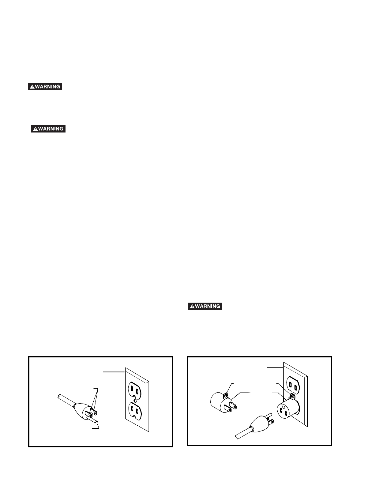
Fig. A Fig. B
GROUNDED OUTLET BOX
CURRENT
CARRYING
PRONGS
GROUNDING BLADE
IS LONGEST OF THE 3 BLADES
GROUNDED OUTLET BOX
GROUNDING
MEANS
ADAPTER
2. Grounded, cord-connected machines intended for
use on a supply circuit having a nominal rating less
than 150 volts:
If the machine is intended for use on a circuit that has an
outlet that looks like the one illustrated in Fig. A, the
machine will have a grounding plug that looks like the plug
illustrated in Fig. A. A temporary adapter, which looks like
the adapter illustrated in Fig. B, may be used to connect
this plug to a matching 2-conductor receptacle as shown in
Fig. B if a properly grounded outlet is not available. The
temporary adapter should be used only until a properly
grounded outlet can be installed by a qualified electrician.
The green-colored rigid ear, lug, and the like, extending
from the adapter must be connected to a permanent
ground such as a properly grounded outlet box. Whenever
the adapter is used, it must be held in place with a metal
screw.
NOTE: In Canada, the use of a temporary adapter is not
permitted by the Canadian Electric Code.
SHOCK HAZARD. IN ALL CASES, MAKE
CERTAIN THE RECEPTACLE IN
QUESTION IS PROPERLY GROUNDED.
IF YOU ARE NOT SURE HAVE A
QUALIFIED ELECTRICIAN CHECK THE
RECEPTACLE.
1. All grounded, cord-connected machines:
In the event of a malfunction or breakdown, grounding
provides a path of least resistance for electric current to
reduce the risk of electric shock. This machine is equipped
with an electric cord having an equipment-grounding
conductor and a grounding plug. The plug must be plugged
into a matching outlet that is properly installed and
grounded in accordance with all local codes and
ordinances.
Do not modify the plug provided - if it will not fit the outlet,
have the proper outlet installed by a qualified electrician.
Improper connection of the equipment-grounding
conductor can result in risk of electric shock. The
conductor with insulation having an outer surface that is
green with or without yellow stripes is the equipmentgrounding conductor. If repair or replacement of the
electric cord or plug is necessary, do not connect the
equipment-grounding conductor to a live terminal.
Check with a qualified electrician or service personnel if the
grounding instructions are not completely understood, or if
in doubt as to whether the machine is properly grounded.
Use only 3-wire extension cords that have 3-prong
grounding type plugs and matching 3-conductor
receptacles that accept the machine’s plug, as shown in
Fig. A.
Repair or replace damaged or worn cord immediately.
POWER CONNECTIONS
Your machine is wired for 120 Volt, 60 HZ alternating current. Before connecting the machine to the power source,
make sure the switch is in the “OFF” position.
GROUNDING INSTRUCTIONS
SHOCK HAZARD. THIS MACHINE MUST BE GROUNDED WHILE IN USE TO PROTECT THE
OPERATOR FROM ELECTRIC SHOCK.
Page 7

7
FOREWORD
ShopMaster Model SM100M is a 10" Compound Power Miter Saw designed to cut wood, plastic, and aluminum.
Compound angle and bevel cutting are easy and accurate. It can crosscut up to 5-3/4" x 2-3/8", miter at 45° both left and
right up to 4-1/8" x 2-3/8", bevel at 45° left up to 5-7/8" x 1-9/16", and compound 45° x 45°,4-1/8" x 1-9/16". It has positive
miter stops at 0°, 22.5°, 31.62°, and 45° both left and right, and bevel stops at 0° and 45° adjustable. Adust bag is included
to catch fine dust and wood chips.
FUNCTIONAL DESCRIPTION
EXTENSION CORDS
Use proper extension cords. Make sure your extension cord is in good condition and is a 3-wire
extension cord which has a 3-prong grounding type plug and matching receptacle which will accept the machine’s plug.
When using an extension cord, be sure to use one heavy enough to carry the current of the machine. An undersized
cord will cause a drop in line voltage, resulting in loss of power and overheating. Fig. C, shows the correct gauge to use
depending on the cord length. If in doubt, use the next heavier gauge. The smaller the gauge number, the heavier the
cord.
MINIMUM GAUGE EXTENSION CORD
RECOMMENDED SIZES FOR USE WITH STATIONARY ELECTRIC MACHINES
Ampere Total Length Gauge of
Rating Volts of Cord in Feet Extension Cord
0-6 120
up to
25 18 AWG
0-6 120 25-50 16 AWG
0-6 120 50-100 16 AWG
0-6 120 100-150 14 AWG
6-10 120
up to
25 18 AWG
6-10 120 25-50 16 AWG
6-10 120 50-100 14 AWG
6-10 120 100-150 12 AWG
10-12 120
up to
25 16 AWG
10-12 120 25-50 16 AWG
10-12 120 50-100 14 AWG
10-12 120 100-150 12 AWG
12-16 120
up to
25 14 AWG
12-16 120 25-50 12 AWG
12-16 120
GREATER THAN 50 FEET NOT RECOMMENDED
NOTICE: The photo on the manual cover illustrates the current production model. All other illustrations contained in the
manual are representative only and may not depict the actual color, labeling, or accessories, and are intended to
illustrate technique only.
Fig. C
Page 8
8
ASSEMBLY
ASSEMBLY TOOLS REQUIRED
(Supplied)
* 5mm hex wrench
* 1/2” Blade wrench
(Not supplied)
* Phillips head screw driver
* A square to make adjustments
UNPACKING AND CLEANING
Carefully unpack the machine and all loose items from the shipping container(s). Remove the protective coating from all unpainted
surfaces. This coating may be removed with a soft cloth moistened with kerosene (do not use acetone, gasoline or lacquer thinner for this
purpose). After cleaning, cover the unpainted surfaces with a good quality household floor paste wax.
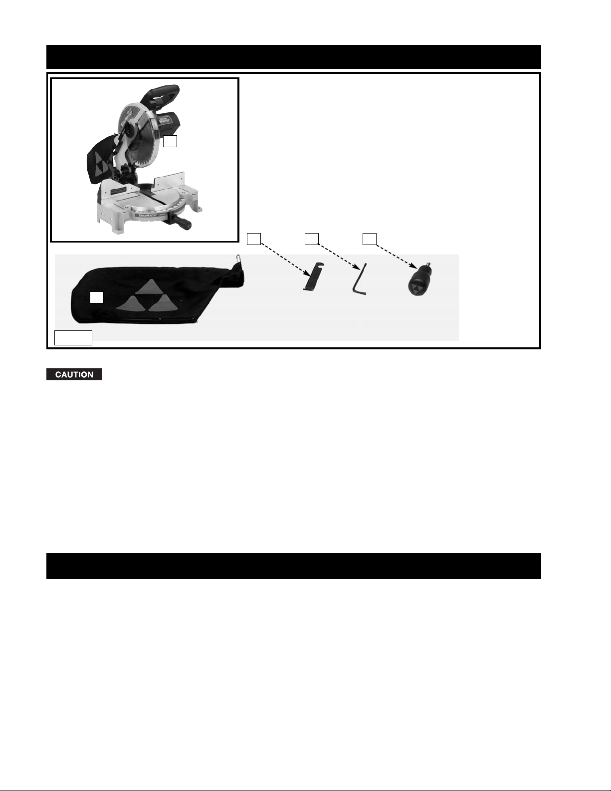
Fig. 1
Remove the miter saw and all loose items from the carton.
Do not lift the miter saw by the switch handle. This action can cause misalignment. Always lift the machine
by the base or the carrying handle.
1. Miter Saw
2. Dust Bag
3. 1/2" Blade Wrench
4. 5mm Hex Wrench
5. Table Lock Handle
CARTON CONTENTS
2
3
4 5
1
Page 9

9
For your own safety, do not connect the machine to the power source until the machine is
completely assembled and you read and understand the entire instruction manual.
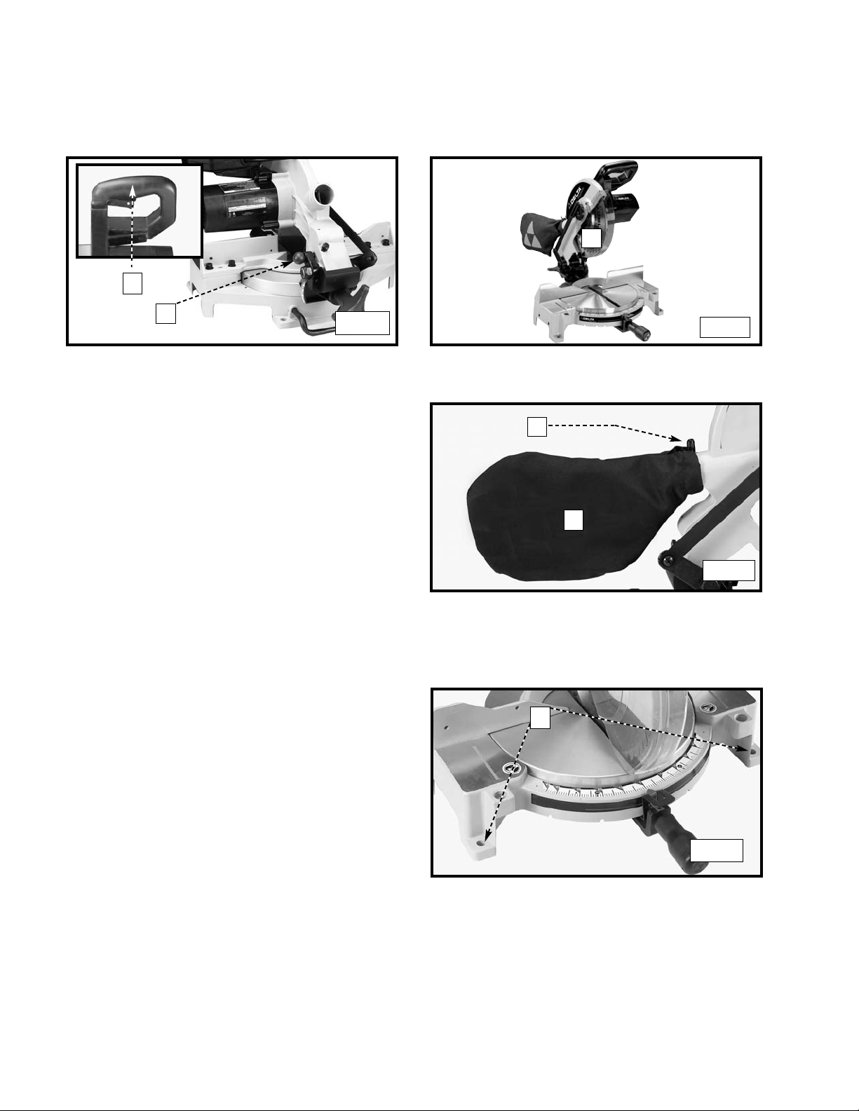
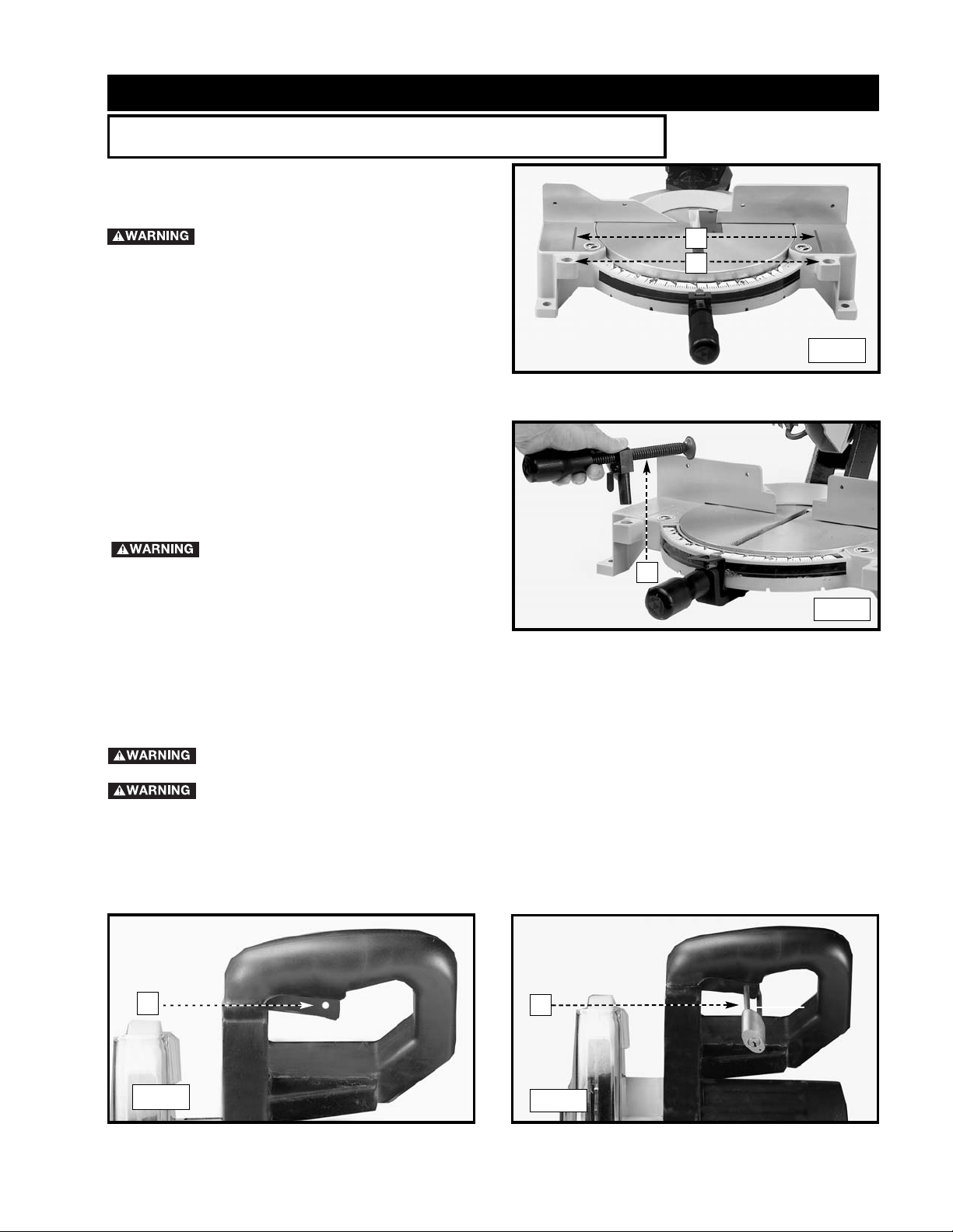
Thread the table lock handle (A) Fig. 2 into the threaded hole (B)
of the arm bracket.
1. Turn the table lock handle (A) Fig. 3 counter-clockwise one
or two turns, and depress the index lever (B) to release the
45° positive stop.
DISCONNECT MACHINE FROM POWER SOURCE!
B
A
Fig. 2
ATTACHING THE TABLE LOCK HANDLE
ROTATING THE TABLE TO THE 90° DEGREE POSITION
Fig. 3
A
B
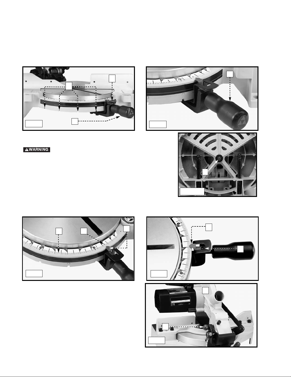
2. Rotate the table to the left until the index stop engages with
the 90° positive stop (Fig. 4). Tighten the table lock handle
(A).
Fig. 4
A
Page 10
10
FASTENING THE MACHINE TO A SUPPORTING SURFACE
Before operating your compound miter saw, make sure that it is
firmly mounted to a sturdy workbench or other supporting
surface. Four holes are provided, two of which are shown at (A)
Fig. 8.
When frequently moving the saw from place to place, mount
the saw on a 3/4" piece of plywood, and clamp the plywood to
a supporting surface with “C” clamps.
1. Push down on handle (A), Inset, Fig. 5. Pull out the cuttinghead lock knob (B).
2. Move the cuttinghead (C) to the up position (Fig. 6).
ATTACHING THE DUST BAG
Squeeze the spring clips (A) Fig. 7 of the dust bag (B) and clip
the dust bag (B) over the ribs of the dust chute.
MOVING CUTTINGHEAD TO THE UP POSITION
Fig. 5
Fig. 6
A
B
C
Fig. 7
A
B
A
Fig. 8
Page 11
A turning saw blade can be dangerous. After completing cut, release switch trigger (A) Fig. 11, to activate
blade brake. Keep cuttinghead down until blade has come to a complete stop.
The torque developed during braking may loosen the arbor screw (E) Fig. 45. The arbor screw should be checked
periodically and tightened if necessary.
11
OPERATION
TABLE HAZARD AREA
The area inside the two red lines on
the table (A) Fig. 9 is designated as a
"HAZARD ZONE". Never place your
hands inside this area while the
machine is running. Maintain hands
6” from blade.
1. An optional work clamp (A) Fig. 10 is available. Use this
accessory clamp, especially with short workpieces. Never
allow your hands to be in the “Hazard Zone”.
2. Two holes (B) Fig. 9 are provided in the base of the miter
saw, enabling you to use the clamp (A) Fig.10 on either the
right or left hand side of the saw blade.
Keep your hands out of path of saw blade.
If necessary, clamp the workpiece in place before making
the cut if hands would be within 6” of the blade.
STARTING AND STOPPING THE MITER SAW
To start the miter saw, depress the switch trigger (A) Fig. 11 To stop the miter saw, release the switch trigger.
This saw is equipped with an automatic electric blade brake. As soon as the switch trigger (A) Fig. 11, is released, the electric brake
is activated and stops the blade in seconds.
OPERATIONAL CONTROLS AND ADJUSTMENTS
USING THE OPTIONAL WORK CLAMP
Fig. 9
A
B
A
LOCKING THE SWITCH IN THE “OFF” POSITION
IMPORTANT: When the miter saw is not in use, the switch should be locked in the "OFF" position using a padlock (B)
Fig. 12, with a 3/16" diameter shackle to prevent unauthorized use of the saw.
Fig. 10
Fig. 11
Fig. 12
A
B
Page 12
12
ADJUSTING THE POINTER
To transport the saw, always lock the cuttinghead in the down
position. Lower the cuttinghead (A) Fig.17, and push the
cuttinghead lock knob (B) into the hole in the cutting arm until it
locks the cuttinghead.
IMPORTANT: Carrying the machine by the switch handle will
cause misalignment. Always lift the machine by the base or
by the carrying handle (See Fig. 20).
Your miter saw will cut any angle from a straight 90° cut to 47° right and left. Turn the lock handle (A) Fig. 13 counter-clockwise
one or two turns, depress the index lever (B), and move the control arm to the desired angle. Tighten the lock handle (A).
The miter saw is equipped with positive stops at the 0°, 22.5°, 31.62°, and 45° right and left positions. Loosen the lock handle (A)
Fig. 14 and move the control arm until the bottom of the index lever (B) engages into one of the positive stops, four of which are
shown at (C). Tighten the lock handle (A). To disengage the positive stop, depress the index lever (B).
A triangle indicator (D) Fig. 15 is provided on the miter scale at the 31.62° right and left miter positions for cutting crown moulding.
(Refer to the “CUTTING CROWN MOULDING” section of this manual).
IMPORTANT: Always tighten the lock handle (A) Fig. 14 before cutting.
POINTER AND SCALE
The pointer (E) Fig. 15 indicates the angle of cut. Each line on the scale (F)
represents 1 degree. When you move the pointer from one line to the next on the
scale, you change the angle of cut by 1 degree.
ROTATING THE TABLE FOR MITER CUTTING
Fig. 13
Fig. 14
C
B
A
A
Fig. 15
F
D
E
To adjust the pointer (E) Fig. 16, loosen the screw (G), adjust the pointer (E), and tighten the screw.
E
G
Fig. 16
LOCKING THE CUTTINGHEAD IN
THE DOWN POSITION
A
B
Fig. 17
ADJUSTING THE SLIDING FIT BETWEEN THE
MOVABLE TABLE AND THE BASE
DISCONNECT THE MACHINE FROM THE POWER
SOURCE .
To adjust the sliding fit between the movable table and the base, turn the
nut (A) Fig. 14A clockwise to increase the sliding fit (opposite to decrease
the fit). This adjustment should not be so tight that it restricts the rotating
movement of the table, or so loose that it affects the accuracy of the saw.
A
Fig. 14A
Page 13
13
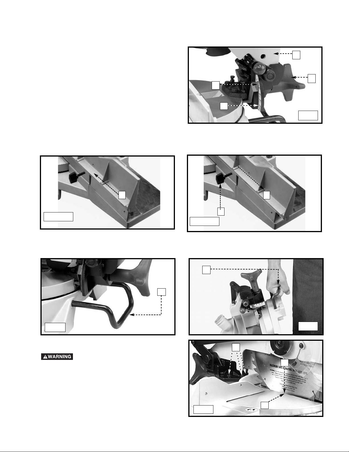
You can tilt the cuttinghead of your compound miter saw to cut
any bevel angle from a 90° straight cut off to a 45° left bevel
angle. Loosen the bevel lock handle (A) Fig. 18, tilt the cutting
arm (B) to the desired angle, and tighten the lock handle (A).
Positive stops are provided to rapidly position the saw blade at
90° and 45° to the table. Refer to the section of this manual
titled “ADJUSTING 90° AND 45° BEVEL STOPS.” The bevel
angle of the cuttinghead is determined by the position of the
pointer (C) Fig.18 on the scale (D).
A triangle indicator is provided on the bevel scale at the 33.86°
bevel angle for cutting crown moulding. Refer to the “CUTTING
CROWN MOULDING” section of this manual.
A rear support bar (A) Fig. 19 is provided to prevent the machine from tipping to the rear when the cuttinghead returns to the up
position. For maximum support, pull the bar (A) out as far as possible.
You can also use the support bar (A) Fig. 20 to carry the machine.
TILTING THE CUTTINGHEAD FOR BEVEL CUTTING
C
B
A
D
Fig. 18
REAR SUPPORT/CARRYING HANDLE
A
Fig. 19
Fig. 20
A
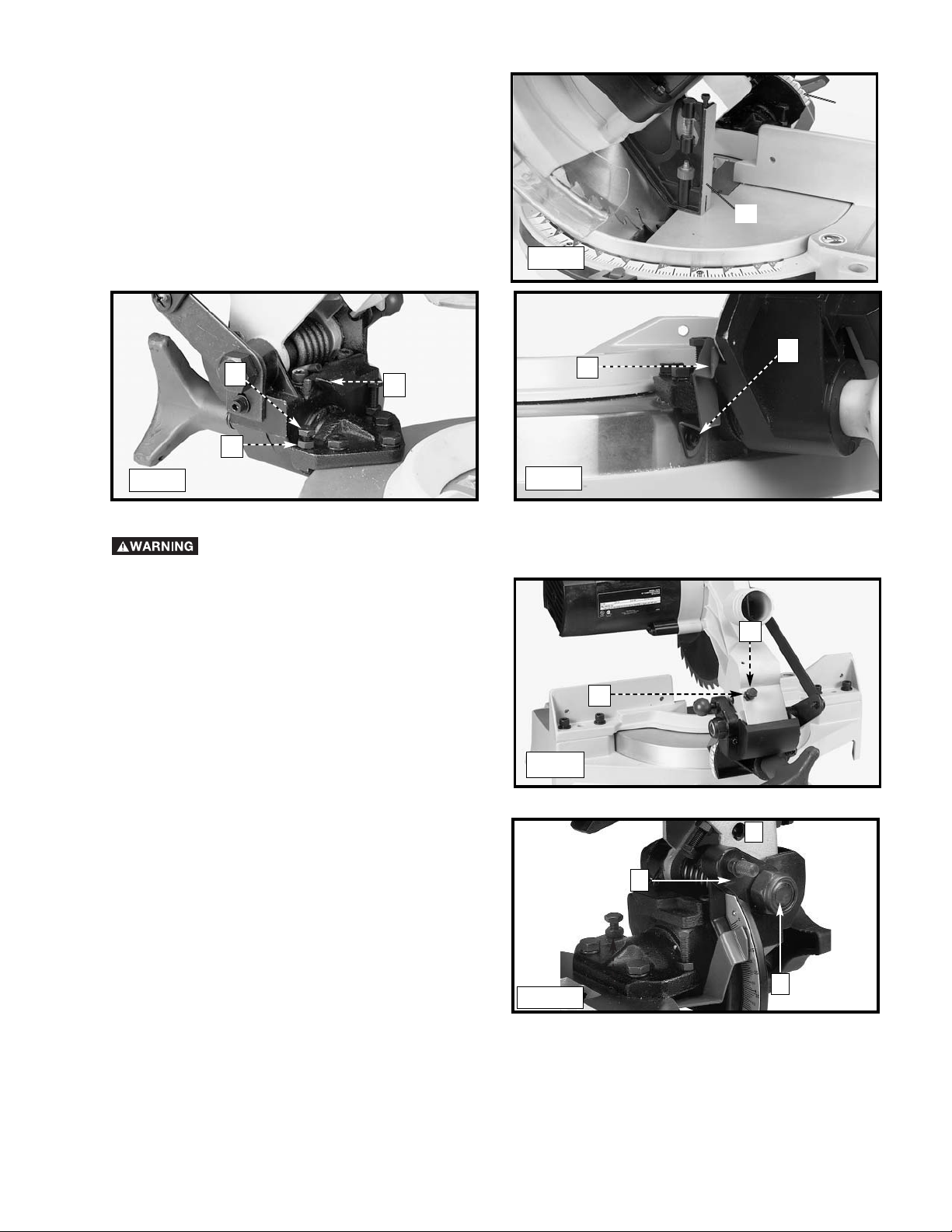
ADJUSTING THE BLADE PARALLEL TO
THE TABLE SLOT
1. Lower the cutting arm. The saw blade (A) Fig. 21 should be
parallel to the left edge (B) of the table opening.
2. To adjust, loosen the three bolts (C) Fig. 21 and move the
cutting arm until the blade is parallel with the left edge (B)
of the table opening and centered in the slot. Tighten the
three bolts (C).
DISCONNECT MACHINE FROM POWER
SOURCE!
Fig. 21
C
B
A
IMPORTANT: Move the sliding fence to provide clearance for the blade and guard. The degree of tilt determines
how far to move the sliding fence. Refer to the section “Adjusting Sliding Fence”.
The sliding fence (A) Fig. 18A provides support for extra large workpieces used with your saw. Set it as close as
possible to the saw blade. When miter cutting (blade 90° to the table and at an angle to the right or left), set the
fence all the way toward the blade (Fig. 18B). When bevel cutting, however (blade tilted at an angle to the table),
move the fence (A) far enough away from the blade to allow for proper clearance. To reposition the fence, loosen the
lock handle (B), and slide the fence (A) to the desired location. Tighten the lock handle (B).
ADJUSTING SLIDING FENCE
Fig. 18A
A
A
B
Fig. 18B
Page 14
14
1. Loosen the bevel lock handle (A) Fig. 18 and move the cutting arm (B) Fig. 19 all the way to the right. Tighten the bevel lock
handle.
2. Place one end of a square (A) Fig. 24 on the table and the other end against the blade. Check to see if the blade is 90° to the
table (Fig. 24).
3. To adjust, loosen the locknut (B) Fig. 25, and turn the screw (C) until the head of the screw (C) contacts the casting (D) when
blade is 90° degrees to the table. Tighten the locknut (B).
1. You can limit the downward travel of the saw blade to
prevent it from contacting any metal surfaces of the
machine. Make this adjustment by loosening the locknut
(A) Fig. 23 and turning the adjusting screw (B) in or out.
2. Lower the blade as far as possible. Rotate the blade by
hand to make certain the teeth do not contact any metal
surfaces.
3. Tighten the locknut (A)
ADJUSTING THE DOWNWARD TRAVEL OF THE SAW BLADE
DISCONNECT MACHINE FROM POWER SOURCE!
Fig. 23
ADJUSTING 90° AND 45° BEVEL STOPS
DISCONNECT MACHINE FROM POWER SOURCE!
A
B
Fig. 24
Fig. 25
A
D
C
B
Fig. 22
In order that the saw can bevel to a full 47 degrees left, the left side of the fence can be adjusted to the left to provide clearance. To
adjust the fence, loosen the plastic knob shown in Figure 22 and slide the fence to the left. Make a dry run with the saw turned off and
check for clearance. Adjust the fence to be as close to the blade as practical to provide maximum workpiece support, without interfering
with arm up & down movement. Tighten knob securely. When the bevel operations are complete, don’t forget to relocate the fence to
the right. NOTE: The guide groove in the left side fence can become clogged with sawdust. If you notice that it is becoming clogged,
use a stick or some low pressure air to clear the guide groove.
FENCE ADJUSTMENT
DISCONNECT MACHINE FROM POWER SOURCE!
Page 15
15
4. Loosen the bevel lock handle. Move the cutting arm all the
way to the left bevel position and tighten the bevel lock
handle.
5. Use a combination square (A) Fig. 26 to see if the blade is
at 45° to the table.
6. To adjust, loosen the locknut (E) Fig. 27, and turn the screw (F)
until it contacts the casting (G). Tighten the locknut (E).
7. Check to see that the bevel pointer (P) Fig. 28 is pointing to the
45° mark on the bevel scale (S) Fig. 26. To adjust the bevel
pointer (P) Fig. 28, loosen the screw (H) and adjust pointer (P).
Tighten the screw (H) securely.
8. These positive stops enable you to rapidly position the blade at
the 90° and 45° bevel angle to the table.
A
S
Fig. 26
Fig. 27
Fig. 28
E
G
F
P
H
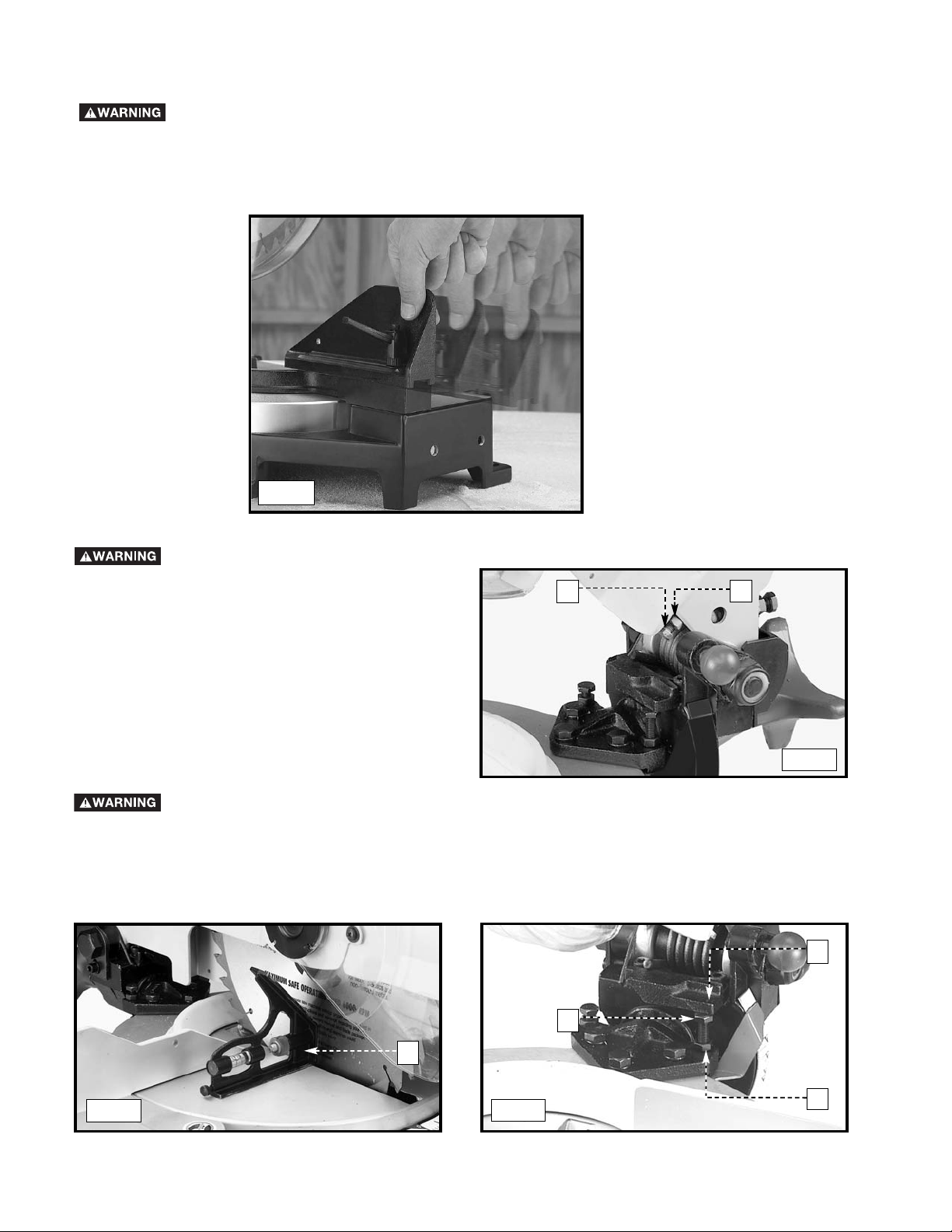
The tension of the cuttinghead return spring was adjusted
at the factory so that the cuttinghead returns to the "up"
position after cutting.
To adjust the spring tension, loosen the locknut (A) Fig.
29 and turn the screw (B) (clockwise to increase or
counterclockwise to decrease the spring tension). After
adjustment, tighten the locknut (A).
ADJUSTING THE TENSION OF THE CUTTINGHEAD RETURN SPRING
CUTTING HEAD MUST RETURN QUICKLY TO THE UP POSITION. DISCONNECT MACHINE
FROM POWER SOURCE.
B
A
Fig. 29
After a long period of time, an adjustment of the sliding fit
between the cuttinghead arm (B) Fig. 29A, and the
trunnion (C) may be necessary. To adjust, tighten the nut
(D). This adjustment should not be so tight that it restricts
the sliding movement of the cuttinghead arm (B) or so
loose that it affects the accuracy of the saw cut.
ADJUSTING SLIDING FIT BETWEEN
CUTTINGHEAD ARM AND TRUNNION
C
D
Fig. 29A
B
Page 16
16
TYPICAL OPERATIONS AND HELPFUL HINTS
1. Before cutting, make certain that the cutting arm and table are at their correct settings and firmly locked in place.
2. Place the workpiece on the table and hold or clamp it firmly against the fence. The optional clamp (A) Fig. 30 can also be used
on the right side of the machine.
3. If the position or size of the workpiece causes your hand to be in the “Hazard Zone”, use the work clamp
to secure the workpiece. Keep your hands out of the “Hazard Zone”.
4. For best results, cut at a slow, even cutting rate.
5. Never attempt freehand cutting (wood that is not held firmly against the fence and table).
Holes are provided in the fence to attach an auxiliary fence (A) Fig. 31. This auxiliary fence is constructed of straight wood
approximately 1/2" thick by 3" high by 20" long.
MACHINE USE
AUXILIARY WOOD FENCE
When performing multiple or repetitive operations that result in small cut-off pieces (one inch or less), the saw
blade can catch the cut-off pieces and project them out of the machine or into the blade guard and housing,
causing damage or injury. To limit the risk, mount an auxiliary wood fence on your saw (Fig. 31).
NOTE: The auxiliary fence (A) is used ONLY with the saw blade in the 0° bevel position (90° to the table). When you bevel cut (blade
tilted), remove the auxiliary fence.
A
A
A
Fig. 30
Fig. 31
Cuttinghead must return quickly to the full up position. Sluggish or incomplete return of the
cuttinghead will effect lower guard operation possibly resulting in personal injury.
DO NOT REMOVE ANY OF THE BLADE GUARDS.
Make sure that all guards are in place and functioning properly before operating the saw.
Make sure that the fences are clear of the guard and blade before operating the saw.
ADJUSTING THE LOWER BLADE
GUARD
DISCONNECT THE MACHINE FROM
POWER SOURCE.
This machine incorporates a blade guard (A) Fig. 29B to
cover the rear section of the blade. After an extended
period of use, the movable lower blade guard may not
operate smoothly when the cuttinghead is lowered. This
can be corrected by adjusting nut (B) until the lower blade
guard moves freely.
Overtightening the nut could impair
guard movement.
NOTE: This unit has been designed with an articulating
rear guard. Before contacting the workpiece, the rear
guard will rotate upward to expose more of the blade as
the cuttinghead is lowered.
Fig. 29B
B
A
Page 17

17
GENERAL CUTTING OPERATIONS
1. Your machine has the capacity to cut standard 2 x 4’s, lying flat or on edge, at the 45° right and left miter angles (Fig. A1 & A2).
2. A standard 2 x 6 can be cut in the 90° straight cut-off position in one pass (Fig. A3).
3. Cutting a standard 4 x 4 can be accomplished with one pass (Fig. A4).
4. This machine has the capacity to accurately cut crown mouldings and other bevel-type cuts (Fig. A5).
5. Cutting various sizes of plastic pipe is an easy job with this machine (Fig. A6). Material must be CLAMPED OR HELD FIRMLY
TO THE FENCE TO KEEP IT FROM ROLLING.
This is extremely important when making angle cuts.
A1 A2
A3
A4
A5
A6
Page 18

18
CUTTING BOWED MATERIAL
Check to see if your workpiece is bowed. If it is, make sure the material is positioned on the table as shown in Fig. 34.
If the material is positioned the wrong way, as shown in Fig. 35, the workpiece will pinch the blade near the completion of the cut.
RIGHT
WRONG
C
B
A
C
WORK SUPPORT EXTENSIONS
For support when cutting long pieces, a work support extension
can be constructed. Fig. 36 illustrates the miter saw mounted to
two standard 2 x 4’s (A). Fasten the four mounting legs (two of
which are shown at (B) Fig. 36 to the 2 x 4’s, using four screws
(not supplied) through the four holes in the mounting legs. The
length of the 2 x 4’s (A) can vary, depending on the kind of work
that will need to be cut.
NOTE: Ensure that the top of the support 2 x 4’s (C) are
level with the miter saw table.
This is critical because the distance from the top of the
2 x 4’s (A) to the miter saw table varies from saw to saw. In
most cases, standard 2 x 4’s (C) can used. If these are too high,
cut the 2 x 4s (C) to provide this height or use other
properly-sized wood.
CUTTING ALUMINUM
Aluminum extrusions such as used for making aluminum screens and storm windows can easily be cut with your compound miter saw.
When cutting aluminum extrusions, or other sections that can be cut with a saw blade and are within the capacity of the machine,
position the material so the blade is cutting through the smallest cross-section (Fig. 32). The wrong way to cut
aluminum angles is illustrated in Fig. 33. Be sure to apply a stick wax to the blade before cutting aluminum stock. This stick wax is
available at most industrial mill supply houses. The wax provides proper lubrication and keeps chips from adhering to the blade.
NEVER APPLY LUBRICANT TO THE BLADE WHILE THE MACHINE IS RUNNING.
FENCE
BLADE
WRONG
FENCE
BLADE
RIGHT
Fig. 33
Fig. 32
Fig. 34
Fig. 35
Fig. 36
Page 19

19
CUTTING CROWN MOULDING
One of the many features of the saw is the ease of cutting crown moulding. The following is an example of cutting both inside and
outside corners on 52°/38° wall angle crown moulding.
1. Move the table to the 31.62° right miter position and lock the table in position. NOTE: A positive stop is provided to find this angle
quickly.
2. Tilt the saw blade to the 33.86° left bevel position and tighten bevel lock handle. NOTE: A triangle indicator is provided on the bevel
scale to find this angle quickly.
3. Place the crown moulding on the table with the CEILING EDGE of the moulding against the fence, and make the cut, as shown in
Fig. 37.
NOTE: The piece of crown moulding used for the outside corner will always be on the right hand side of the blade, as shown at (A)
Fig. 37. The piece of crown moulding used for the inside corner will always be on the left hand side of the blade, as shown at (B)
Fig. 37.
4. To make the matching halves of the inside and outside corners, rotate the table to the 31.62° left miter position.
NOTE: A positive stop is provided to find this angle quickly. The saw blade is already tilted to the 33.86° left bevel position from the
previous cut.
5. Place the crown moulding on the table with the WALL EDGE of the crown moulding against the fence and make the cut. Again, the
piece of crown moulding used for the outside corner will always be on the right side of the blade, as shown at (C) Fig. 38. The piece
of crown moulding used for the inside corner will always be on the left side of the blade, as shown at (D) Fig. 38.
6. Fig. 39 illustrates the two outside corner pieces; (A) being the piece cut at (A) Fig. 37 and (C) being the piece cut at (C) Fig. 38.
7. Fig. 40 illustrates the two inside corner pieces; (B) being the piece cut at (B) Fig. 37, and (D) being the piece cut at (D) Fig. 38.
45-45 CROWN MOULDING
NOTE: If you are cutting crown moulding that is 45°-45°, follow the same procedure above, with the exception that the bevel position
will always be at 30° and the miter position will be 35-1/4° to the right or left.
OTHER ANGLES
NOTE: The above instructions are assuming the angle between the walls is 90°. If you need help cutting crown moulding set at angles
other than 90°, see the instruction sheet “CUTTING CROWN MOULDING” on the Delta Machinery web site at
www.deltamachinery.com.
Fig. 38
Fig. 37
Fig. 39
Fig. 40
D
C
B
A
C
A
B
D
WALL
EDGE
CEILING
EDGE
Page 20

20
Brush life varies. It depends on the load on the motor. Check the brushes after the first 50 hours of use for a new machine or after
a new set of brushes has been installed. After the first check, examine them after about 10 hours of use until a replacement is
necessary. To inspect the brushes:
MAINTENANCE
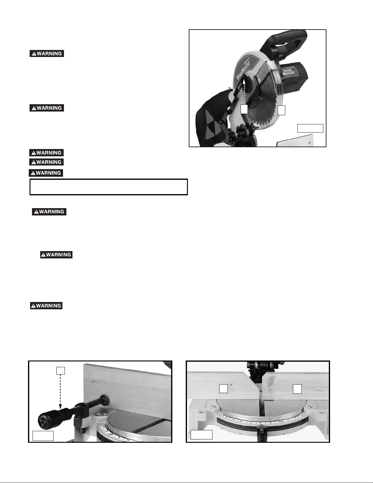
CHANGING THE BLADE
Use only cross-cutting saw blades.
When using carbide-tipped blades, do not
use blades with deep gullets as they can
deflect and contact the guard.
Use only 10" diameter saw blades which are
rated for 5200 rpm or higher and have 5/8"
diameter arbor holes.
1. Remove screw (A) Fig. 41 and rotate cover (B) to the rear
(Fig. 42).
2. To remove the saw blade, insert the hex wrench (C)
Fig. 43 into the hex hole located on the rear end of the
motor shaft to keep the shaft from turning.
3. Use a wrench (D) Fig. 44 to loosen the arbor screw (E) by
turning it clockwise.
4. Remove the arbor screw (E) Fig. 44, the outside blade
flange (B), and the saw blade from the saw arbor.
5. Attach the new saw blade
making certain that the teeth of
the saw blade are pointing down (Fig. 44). Place the
outside blade flange (F) on the arbor, and attach the arbor
screw (E) by turning it counter-clockwise using the wrench
(D). At the same time, use the hex wrench (C) Fig. 43 to
keep the arbor from turning.
6. Rotate the cover back to the front and replace the screw
that was removed in STEP 1.
DISCONNECT MACHINE FROM POWER SOURCE!
Remove wrenches (C) Fig. 43 and (D) Fig. 44
before starting machine.
The cover must be returned to its original
position and the screw tightened before
activating the saw. Failure to do so may
allow the guard to contact the spinning saw
blade resulting in damage to the saw and
severe personal injury.
Fig. 41
Fig. 42
Fig. 43
Fig. 44
A
B
B
C
E
F
D
T
E
E
T
H
BRUSH INSPECTION AND REPLACEMENT
DISCONNECT MACHINE FROM POWER SOURCE!
Page 21

1. Remove three screws (A) Fig. 45 and remove the motor
cover (B).
2. The brushes are located in the two holders (C) Fig. 46.
Remove spade type terminal connector (D) and pull out
brush holders (C).
3. Fig. 47 illustrates one of the brushes (E) removed from the
holder (C). When the carbon on either brush (E) is worn to
3/16" in length or if either spring (F) or shunt wire is burned
or damaged in any way, replace both brushes. If the
brushes are found to be serviceable after re-moving,
reinstall them in the same position.
21
TROUBLESHOOTING
BE SURE TO FOLLOW SAFETY RULES AND INSTRUCTIONS
TROUBLE! SAW WILL NOT START
WHAT’S WRONG? WHAT TO DO…
1.Saw not plugged in. 1.Plug in saw.
2.Fuse blown or circuit breaker tripped. 2.Replace fuse or reset
circuit breaker.
3.Cord damaged. 3.Have cord replaced by
authorized service center.
4.Brushes worn out. 4.Have brushes replaced
by authorized service center.
TROUBLE! SAW MAKES UNSATISFACTORY CUTS
WHAT’S WRONG? WHAT TO DO…
1.Dull blade. 1.Replace blade.
2.Blade mounted backwards. 2.Turn blade around.
3.Gum or pitch on blade. 3.Remove blade and
clean with turpentine.
4.Incorrect blade for work being done. 4.Change the blade.
TROUBLE! BLADE DOES NOT COME UP TO SPEED
WHAT’S WRONG? WHAT TO DO…
1.Extension cord too light or too long. 1.Replace with adequate
size cord.
2.Low house current. 2.Contact your electric
company.
KEEP THE MACHINE CLEAN
Periodically blow out all air passages with dry compressed air. All plastic parts should be cleaned with a soft damp cloth.
NEVER use solvents to clean plastic parts. They could possibly dissolve or otherwise damage the material.
Wear ANSI Z87.1 safety glasses while using compressed air.
FAILURE TO START
Should your machine fail to start, check to make sure the prongs on the cord plug are making good contact in the outlet. Also, check
for blown fuses or open circuit breakers in the line.
B
A
Fig. 45
Fig. 46
Fig. 47
D
C
C
E
F
Page 22

22
PARTS, SERVICE OR WARRANTY ASSISTANCE
All Delta Machines and accessories are manufactured to high quality standards and are serviced by a network of PorterCable · Delta Factory Service Centers and Delta Authorized Service Stations. To obtain additional information regarding
your Delta quality product or to obtain parts, service, warranty assistance, or the location of the nearest service outlet,
please call 1-800-223-7278 (In Canada call 1-800-463-3582).
A complete line of accessories is available from your Delta Supplier, Porter-Cable · Delta Factory Service Centers,
and Delta Authorized Service Stations. Please visit our Web Site www.deltamachinery
.com
for a catalog or for
the name of your nearest supplier.
Since accessories other than those offered by Delta have not been tested
with this product, use of such accessories could be hazardous. For safest operation, only
Delta recommended accessories should be used with this product.
ACCESSORIES
Two Year Limited New Product Warranty
Delta will repair or replace, at its expense and at its option, any new Delta machine, machine part, or machine accessory
which in normal use has proven to be defective in workmanship or material, provided that the customer returns the product
prepaid to a Delta factory service center or authorized service station with proof of purchase of the product within two
years and provides Delta with reasonable opportunity to verify the alleged defect by inspection. For all refurbished Delta
product, the warranty period is 180 days. Delta may require that electric motors be returned prepaid to a motor
manufacturer’s authorized station for inspection and repair or replacement. Delta will not be responsible for any asserted
defect which has resulted from normal wear, misuse, abuse or repair or alteration made or specifically authorized by
anyone other than an authorized Delta service facility or representative. Under no circumstances will Delta be liable for
incidental or consequential damages resulting from defective products. This warranty is Delta’s sole warranty and sets
forth the customer’s exclusive remedy, with respect to defective products; all other warranties, express or implied, whether
of merchantability, fitness for purpose, or otherwise, are expressly disclaimed by Delta.
SERVICE
WARRANTY
TROUBLE! MACHINE VIBRATES EXCESSIVELY
WHAT’S WRONG? WHAT TO DO…
1.Saw not mounted securely. 1.Tighten all mounting
hardware.
2.Stand or bench on uneven floor. 2.Reposition on flat level
surface.
3.Damaged saw blade. 3.Replace blade.
TROUBLE! DOES NOT MAKE ACCURATE MITER CUTS
WHAT’S WRONG? WHAT TO DO…
1.Miter scale not adjusted correctly. 1.Check and adjust.
2.Blade is not square to fence. 2.Check and adjust.
3.Blade is not perpendicular to table. 3.Check and adjust fence.
4.Workpiece moving. 4.Clamp workpiece to
fence or glue 120 grit
sandpaper to fence with
rubber cement.
TROUBLE! MATERIAL PINCHES BLADE
WHAT’S WRONG? WHAT TO DO…
1.Cutting bowed material. 1.Position bowed material
as shown in Figure 36.
Page 23

23
23
Para obtener más información sobre Delta Machinery,
visite nuestro sitio web en: www.deltamachinery.com
Para las piezas, el servicio, la garantía o la otra ayuda llaman por favor
1-800-223-7278
(
en la llamada 1-800-463-3582 de Canada).
MANUAL DE INSTRUCCIONES
Sierra de Ingletes Compuesta
Motorizada de 254 mm
(Modelo SM100M)
90513776 1-07
Copyright © 2007 Delta Machinery
Page 24

2424
Lea y entienda todas advertencias y las instrucciones operadoras antes de utilizar cualquier instrumento o el equipo.
Cuando se usa instrumentos o equipo, las precauciones básicas de la seguridad siempre se deben seguir para reducir el riesgo de la herida
personal. La operación impropia, la conservación o la modificación de instrumentos o equipo podrían tener como resultado el daño grave
de la herida y la propiedad. Hay ciertas aplicaciones para que equipaas con herramienta y el equipo se diseña. La Delta Machinery
recomienda totalmente que este producto no sea modificado y/o utilizado para ninguna aplicación de otra manera que para que se diseñó.
Si usted tiene cualquiera pregunta el pariente a su aplicación no utiliza el producto hasta que usted haya escrito Delta Machinery y nosotros
lo hemos aconsejado.
La forma en línea del contacto en www. deltamachinery. com
El Correo Postal: Technical Service Manager
Delta Machinery
4825 Highway 45 North
Jackson, TN 38305
(IN CANADA: 125 Mural St. Suite 300, Richmond Hill, ON, L4B 1M4)
Información con respecto a la operación segura y apropiada de este instrumento está disponible de las fuentes siguientes:
Power Tool Institute (Instituto de Herramientas Eléctricas)
1300 Sumner Avenue, Cleveland, OH 44115-2851
www.powertoolinstitute.org
Consejo Nacional de Seguridad (National Safety Council)
1121 Spring Lake Drive, Itasca, IL 60143-3201
American National Standards Institute, 25 West 43rd Street, 4 floor, New York, NY 10036 www.ansi.org
Requisitos de Seguridad ANSI 01.1 para las máquinas de carpintería y
normas del Departamento del Trabajo de los Estados Unidos www.osha.gov
INSTRUCCIONES DE SEGURIDAD IMPORTANTES
GUARDE ESTAS INSTRUCCIONES!
Page 25

25
indica una situación de peligro inminente que, si no se evita, provocará la muerte o lesiones graves.
indica una situación de peligro potencial que, si no se evita, provocará la muerte o lesiones graves.
indica una situación de peligro potencial que, si no se evita, provocará lesiones leves o moderadas.
utilizado sin el símbolo de alerta de seguridad indica una situación de peligro potencial que, si no se evita,
puede provocar daños en la propiedad.
Es importante que lea y comprenda este manual. La información que contiene se relaciona con la
protección de SU SEGURIDAD y la PREVENCIÓN DE PROBLEMAS. Los símbolos que siguen se utilizan
para ayudarlo a reconocer esta información.
PAUTAS DE SEGURIDAD/DEFINICIONES
LA PROPUESTA 65 DE CALIFORNIA
Algunas partículas originadas al lijar, aserrar, amolar, taladrar y realizar otras actividades de construcción
contienen productos químicos que producen cáncer, defectos de nacimiento y otros problemas
reproductivos. Algunos ejemplos de estos productos químicos son:
• el plomo de las pinturas a base de plomo;
• la sílice cristalina de ladrillos, el cemento y otros productos de mampostería; y
• el arsénico y el cromo de la madera con tratamiento químico (CCA).
El riesgo derivado de estas exposiciones varía según la frecuencia con la que se realice este tipo de trabajo. Para reducir la
exposición a estos productos químicos: se recomienda trabajar en áreas bien ventiladas y usar equipos de seguridad aprobados,
como las máscaras para polvo especialmente diseñadas para filtrar las partículas microscópicas.
• Evite el contacto prolongado con las partículas de polvo originadas al lijar, aserrar, esmerilar, taladrar y realizar demás actividades de
la construcción. Use indumentaria protectora y lave las áreas expuestas con agua y jabón. Evite que el polvo entre en la boca y en los
ojos o se deposite en la piel, para impedir la absorción de productos químicos nocivos.
El uso de esta herramienta puede generar o dispersar partículas de polvo, que pueden causar lesiones respiratorias
permanentes y graves u otras lesiones. Use siempre protección respiratoria aprobada por NIOSH/OSHA (Instituto Nacional de
Salud y Seguridad Ocupacional de los EE.UU./Administración de la Salud y Seguridad Ocupacional de los EE.UU.) apropiada para la
exposición al polvo. Aleje la cara y el cuerpo del contacto con las partículas.
Utilice la protección auditiva apropiada durante el uso. En determinadas condiciones y según el período de uso, el ruido
provocado por este producto puede originar pérdida de audición.
Para su comodidad y seguridad, la herramienta incluye las siguientes etiquetas de advertencia.
EN LA
CAJA
DEL MOT
OR:
ADVERTENCIA: POR SU PROPIA SEGURIDAD, LEA EL MANUAL DE INSTRUCCIONES ANTES DE OPERAR LA SIERRA. AL
REPARAR, SÓLO UTILICE PIEZAS DE REPUESTO IDÉNTICAS. SIEMPRE UTILICE PROTECCIÓN PARA LOS OJOS.
EN LA
GUÍA:
AJUSTE LAS PIEZAS PEQUEÑAS ANTES DE CORTAR.
CONSULTE EL MANUAL.
EN LA
GUARDA: PELIGRO – MANTÉNGASE ALEJADO DE LA HOJA.
EN LA
PLACA DE RETENCIÓN DE LA GUARDA: “SUJETE EL SOPORTE CORRECTAMENTE CON
AMBOS TORNILLOS ANTES DE USAR”
CLAMP SMALL PIECES
BEFORE CUTTING. SEE MANUAL.
DANGER
KEEP AWAY
FROM BLADE
EN LA TABLA (2 LUGARES)
EN LA PLACA DE RETENCIÓN DEL PROTECTOR: PARA REDUCIR EL RIESGO DE LESIONES, LEA EL MANUAL DE
INSTRUCCIONES ANTES DE OPERAR LA SIERRA INGLETADORA. AL REALIZAR EL MANTENIMIENTO, SÓLO UTILICE
PIEZAS DE REPUESTO IDÉNTICAS. NO EXPONGA A LA LLUVIA NI UTILICE EN LUGARES HÚMEDOS. SIEMPRE UTILICE
PROTECCIÓN ADECUADA PARA LOS OJOS Y VÍAS RESPIRATORIAS. UTILICE ÚNICAMENTE HOJAS DE SIERRA DE 10”
RECOMENDADAS PARA 5.200 RPM O MÁS, CON EJE DE 5/8”. MANTENGA LAS MANOS ALEJADAS DEL TRAYECTO DE LA
HOJA DE LA SIERRA. NO OPERE LA SIERRA SI LOS PROTECTORES NO ESTÁN ADECUADAMENTE INSTALADOS.
VERIFIQUE QUE EL PROTECTOR INFERIOR CIERRE CORRECTAMENTE ANTES DE CADA USO. AJUSTE SIEMPRE LAS
PERILLAS DE REGULACIÓN ANTES DE UTILIZAR LA HERRAMIENTA. NO REALICE NINGUNA OPERACIÓN SIN MANOS.
NUNCA SE ESTIRE PARA ALCANZAR ALGO DETRÁS DE LA HOJA DE LA SIERRA. NUNCA CRUCE LOS BRAZOS FRENTE A
LA HOJA. APAGUE LA HERRAMIENTA Y AGUARDE HASTA QUE LA HOJA DE LA SIERRA SE DETENGA ANTES DE MOVER
LA PIEZA DE TRABAJO, CAMBIAR LOS AJUSTES O MOVER LAS MANOS. DESCONECTE LA ENERGÍAANTES DE CAMBIAR
LA HOJA O REALIZAR EL MANTENIMIENTO. PARA REDUCIR EL RIESGO DE LESIONES, REGRESE EL MECANISMO DE
TRANSPORTE A LA POSICIÓN POSTERIOR DESPUÉS DE CADA CORTE TRANSVERSAL. ¡PRESTE ATENCIÓN! PUEDE
EVITAR ACCIDENTES.
NO EXPONGA A LA LLUVIA NI LA UTILICE EN LUGARES HÚMEDOS.
Page 26

26
NORMAS GENERALES DE SEGURIDAD
1. PARA SU PROPIA SEGURIDAD, LEA EL MANUAL DE
INSTRUCCIONES ANTES DE UTILIZAR LA MÁQUINA.
Al aprender la aplicación, las limitaciones y los peligros
específicos de la máquina, se minimizará enormemente
la posibilidad de accidentes y lesiones.
2. USE PROTECCIÓN DE LOS OJOS Y DE LA
AUDICIÓN. USE SIEMPRE ANTEOJOS DE
SEGURIDAD. Los lentes de uso diario NO son anteojos
de seguridad. USE EQUIPO DE SEGURIDAD
CERTIFICADO. El equipo de protección de los ojos debe
cumplir con las normas ANSI Z87.1. El equipo de
protección de la audición debe cumplir con las normas
ANSI S3.19.
3. USE INDUMENTARIA ADECUADA. No use ropa
holgada, guantes, corbatas, anillos, pulseras u otras
joyas que podrían engancharse en las piezas móviles. Se
recomienda usar calzado antideslizante. Use una
cubierta protectora del pelo para sujetar el pelo largo.
4. NO UTILICE LA MÁQUINA EN UN ENTORNO
PELIGROSO. La utilización de herramientas mecánicas
en lugares húmedos o mojados, o en la lluvia, puede
causar descargas eléctricas o electrocución. Mantenga
bien iluminada el área de trabajo para evitar tropezar o
poner en peligro los brazos, las manos y los dedos.
5. MANTENGA TODAS LAS HERRAMIENTAS Y
MÁQUINAS EN CONDICIONES ÓPTIMAS. Mantenga
las herramientas afiladas y limpias para lograr el mejor y
más seguro rendimiento. Siga las instrucciones de
lubricación y cambio de accesorios. Las herramientas y
las máquinas mal mantenidas pueden dañar más la
herramienta o la máquina y/o causar lesiones.
6. COMPRUEBE SI HAY PIEZAS DAÑADAS. Antes de
utilizar la máquina, compruebe si hay piezas dañadas.
Compruebe la alineación de las piezas móviles, si las
piezas móviles se atascan, si hay piezas rotas y toda
otra situación que podría afectar su funcionamiento. Un
protector o cualquier otra pieza que presente daños
debe repararse o reemplazarse apropiadamente. Las
piezas dañadas pueden causar daños adicionales a la
máquina y/o lesiones.
7. MANTENGA LIMPIA EL ÁREA DE TRABAJO. Las
áreas y los bancos desordenados invitan a que se
produzcan accidentes.
8. MANTENGA ALEJADOS A LOS NIÑOS Y A LOS
VISITANTES. El taller es un entorno potencialmente
peligroso. Los niños y los visitantes pueden sufrir
lesiones.
9. REDUZCA EL RIESGO DE UN ARRANQUE NO
INTENCIONADO. Asegúrese de que el interruptor esté
en la posición de apagado antes de enchufar el cable de
alimentación. En caso de un apagón, mueva el
interruptor a la posición de apagado. Un arranque
accidental podría causar lesiones.
10.UTILICE LOS PROTECTORES. Asegúrese de que todos
los protectores estén colocados en su sitio, sujetos
firmemente y funcionando correctamente para prevenir
lesiones.
11.QUITE LAS LLAVES DE AJUSTE Y DE TUERCA
ANTES DE ARRANCAR LA MÁQUINA. Las
herramientas, los pedazos de desecho y otros residuos
pueden salir despedidos a alta velocidad, causando
lesiones.
12.UTILICE LA MÁQUINA ADECUADA. No fuerce una
máquina o un aditamento a hacer un trabajo para el que
no se diseñó. El resultado podría ser daños a la máquina
y/o lesiones.
13.UTILICE ACCESORIOS RECOMENDADOS. La
utilización de accesorios y aditamentos no
recomendados por Delta podría causar daños a la
máquina o lesiones al usuario.
14.UTILICE EL CORDÓN DE EXTENSIÓN ADECUADO.
Asegúrese de que el cordón de extensión esté en
buenas condiciones. Cuando utilice un cordón de
extensión, asegúrese de utilizar un cordón que sea lo
suficientemente pesado como para llevar la corriente
que su producto tome. Un cordón de tamaño
insuficiente causará una caída de la tensión de la línea,
lo cual producirá una pérdida de potencia y
recalentamiento. Consulte el Cuadro de cordones de
extensión para obtener el tamaño correcto dependiendo
de la longitud del cordón y la capacidad nominal en
amperios indicada en la placa de especificaciones. En
caso de duda, utilice el próximo calibre más grueso.
Cuanto más pequeño sea el número de calibre, más
pesado será el cordón.
15.SUJETE FIRMEMENTE LA PIEZA DE TRABAJO.
Utilice abrazaderas o un tornillo de carpintero para
sujetar la pieza de trabajo cuando resulte práctico. La
pérdida de control de una pieza de trabajo puede causar
lesiones.
16.HAGA AVANZAR LA PIEZA DE TRABAJO CONTRA
EL SENTIDO DE ROTACIÓN DE LA HOJA, EL
CORTADOR O LA SUPERFICIE ABRASIVA. Si la hace
avanzar desde el otro sentido, el resultado será que la
pieza de trabajo salga despedida a alta velocidad.
17.NO FUERCE LA PIEZA DE TRABAJO SOBRE LA
MÁQUINA. El resultado podría ser daños a la máquina
y/o lesiones.
18.NO INTENTE ALCANZAR DEMASIADO LEJOS. Una
pérdida del equilibrio puede hacerle caer en una
máquina en funcionamiento, causándole lesiones.
19.NO SE SUBA NUNCA A LA MÁQUINA. Se podrían
producir lesiones si la herramienta se inclina o si usted
hace contacto accidentalmente con la herramienta de
corte.
20.NO DEJE NUNCA DESATENDIDA LA MÁQUINA
CUANDO ESTÉ EN MARCHA. APÁGUELA. No deje la
máquina hasta que ésta se detenga por completo. Un
niño o un visitante podría resultar lesionado.
21.APAGUE LA MÁQUINA Y DESCONÉCTELA DE LA
FUENTE DE ALIMENTACIÓN antes de instalar o quitar
accesorios, antes de ajustar o cambiar configuraciones
o al realizar reparaciones. Un arranque accidental puede
causar lesiones.
22.HAGA SU TALLER A PRUEBA DE NIÑOS CON
CANDADOS E INTERRUPTORES MAESTROS O
QUITANDO LAS LLAVES DE ARRANQUE. El arranque
accidental de una máquina por un niño o un visitante
podría causar lesiones.
23.MANTÉNGASE ALERTA, FÍJESE EN LO QUE ESTÁ
HACIENDO Y USE EL SENTIDO COMÚN. NO UTILICE
LA MÁQUINA CUANDO ESTÉ CANSADO O BAJO LA
INFLUENCIA DE DROGAS, ALCOHOL O MEDICAMENTOS. Un momento de distracción mientras se
estén utilizando herramientas mecánicas podría causar
lesiones.
24. EL POLVO GENERADO por determinadas maderas y
productos para madera puede ser perjudicial para su
salud. Siempre opere la máquina en áreas con buena
ventilación y encárguese de eliminar el polvo
adecuadamente. Utilice un sistema de recolección de
polvo, cuando esto sea posible.
LEA Y COMPRENDA TODAS LAS ADVERTENCIAS Y LAS INSTRUCCIONES DE
OPERACIÓN ANTES DE UTILIZAR ESTE EQUIPO. El incumplimiento de cualquiera de las
instrucciones enumeradas abajo puede provocar descarga eléctrica, incendio o lesiones
personales graves o daños a la propiedad.
INSTRUCCIONES IMPORTANTES SOBRE SEGURIDAD
Page 27

27
1. NO UTILICE ESTA MÁQUINA HASTA QUE esté
montada e instalada de acuerdo con las
instrucciones.
2. OBTENGA ASESORAMIENTO de su supervisor,
instructor u otra persona calificada si no está
familiarizado con la utilización de esta máquina.
3. SIGA TODOS LOS CÓDIGOS DE CABLEADO y
las conexiones eléctricas recomendadas.
4. MONTE LA HERRAMIENTA FIRMEMENTE en una
superficie de soporte estable antes de utilizarla.
5. UTILICE LOS PROTECTORES SIEMPRE QUE
SEA POSIBLE. Asegúrese de que estén colocados
en su sitio, sujetos firmemente y funcionando
correctamente.
6. UTILICE ÚNICAMENTE HOJAS DE SIERRA DE
CORTE TRANSVERSAL. Utilice únicamente
ángulos de gancho de cero grados o negativos
cuando emplee hojas con puntas de carburo. No
utilice hojas que tengan gargantas profundas. Estas
hojas pueden doblarse y entrar en contacto con el
protector.
7. USE SÓLO HOJAS DEL TAMAÑO Y TIPO
CORRECTO especificadas para esta herramienta.
8. USE UNA HOJA AFILADA. Compruebe la hoja
para ver si funciona libremente y si está libre de
vibraciones.
9. INSPECCIONE LA HOJA PARA VER SI TIENE
GRIETAS u otros daños antes de utilizarla.
Reemplace inmediatamente la hoja agrietada o
dañada.
10.LIMPIE LA HOJA Y LAS PESTAÑAS DE LA HOJA
antes de utilizarla. Compruebe si la hoja tiene daños
y apriete firmemente la tuerca del eje
portaherramienta.
11.USE SÓLO LAS PESTAÑAS DE HOJA
especificadas para esta herramienta.
12.DESPEJE EL ÁREA DE LÍQUIDOS INFLAMABLES
y/o gases inflamables antes de utilizar la máquina.
13.LIMPIE LAS RANURAS DE VENTILACIÓN DEL
MOTOR para quitar las virutas y el serrín.
14. APRIETE EL MANGO DE LA ABRAZADERA DE
LA MESA y cualquier otra abrazadera antes de
utilizar la máquina.
15.NUNCA ARRANQUE LA HERRAMIENTA con la
pieza de trabajo contra la hoja.
16.MANTENGA LAS MANOS alejadas de la
trayectoria de la hoja de sierra. Sujete con
abrazaderas todas las piezas de trabajo que
requerirían que la mano esté en la "Zona de peligro
de la mesa" (dentro de las líneas rojas).
17.DEJE QUE EL MOTOR alcance su velocidad
máxima antes de comenzar el corte.
18. NUNCA PONGA LAS MANOS ALREDEDOR ni
detrás de la hoja de sierra.
19.NUNCA CORTE METALES FERROSOS ni
mampostería.
20.NUNCA CORTE DE NUEVO PEDAZOS
PEQUEÑOS.
21.NUNCA BLOQUEE EL INTERRUPTOR en la
posición de encendido.
21.NO APLIQUE LUBRICANTE a una hoja que esté
en marcha.
GUARDE ESTAS INSTRUCCIONES.
Refiérase a ellas con frecuencia y utilícelas para adiestrar a otros.
22. NO REALICE OPERACIONES A PULSO. Sujete
firmemente la pieza de trabajo contra el tope-guía y
la mesa. Use abrazaderas para sujetar la pieza de
trabajo cuando sea posible.
23. SOPORTE APROPIADAMENTE las piezas de
trabajo LARGAS o anchas.
24.DESPUÉS DE COMPLETAR EL CORTE, suelte el
interruptor de alimentación y espere a que la hoja
que gira por inercia se detenga por completo antes
de regresar la sierra a la posición subida.
25.APAGUE LA HERRAMIENTA Y DEJE QUE LA
HOJA SE DETENGA POR COMPLETO antes de
limpiar el área de la hoja o quitar los residuos que
estén en la trayectoria de la hoja. Una hoja que gira
por inercia hasta detenerse es peligrosa.
26.APAGUE LA HERRAMIENTA Y DEJE QUE LA
HOJA SE DETENGA POR COMPLETO antes de
retirar o sujetar la pieza de trabajo, cambiar el
ángulo de la pieza de trabajo o cambiar el ángulo
de la hoja.
27.NUNCA REALICE TRABAJO DE INSTALACIÓN,
MONTAJE o preparación en el área de la mesa o de
trabajo cuando la máquina esté en marcha.
28.APAGUE LA MAQUINA Y DESCONÉCTELA de la
fuente de alimentación antes de instalar o quitar
accesorios, antes de ajustar o cambiar
preparaciones o al hacer reparaciones.
29.APAGUE LA MÁQUINA, desconéctela de la fuente
de alimentación y limpie el área de la mesa y de
trabajo antes de dejar la máquina. BLOQUEE EL
INTERRUPTOR EN LA POSICIÓN DE APAGADO
para impedir el uso no autorizado.
30.NO TIRE DE ESTA UNIDAD POR EL CABLE DE
ALIMENTACIÓN. No deje que el cable de
alimentación entre en contacto con instrumentos o
bordes afilados, superficies calientes, aceite o
grasa. No ponga ningún peso sobre el cable de
alimentación. Un cable de alimentación dañado
puede causar descargas eléctricas o electrocución.
31.ANTES OPERAR EL VIO. El cheque y cierra
seguramente el bisel, mitra, y los ajustes de la cerca
de sliding.
32. EL CABEZAL DE CORTE DEBE VOLVER
RÁPIDAMENTE A LA POSICIÓN MÁS ALTA. De lo
contrario, el protector inferior no funcionará
adecuadamente y eso puede ocasionar lesiones
personales. Consulte la sección del manual referida al
“Ajuste del retorno del cabezal de corte”.
33.HAY INFORMACIÓN ADICIONAL disponible
relacio-nada con la utilización segura y apropiada
de herrami-entas mecánicas (por ejemplo, un video
sobre seguridad) a través del Instituto de
Herramientas Mecánicas, Power Tool Institute, 1300
Sumner Avenue, Cleveland, OH 44115-2851
(www.powertool-institute.com). También hay
información disponible a través del Consejo
Nacional de Seguridad, National Safety Council,
1121 Spring Lake Drive, Itasca, IL 60143-3201.
Sírvase consultar también los Requisitos de
Seguridad para Máquinas de Elaboración de la
Madera ANSI 01.1 del Instituto Nacional Americano
de Normas (American National Standards Institute)
y las normas OSHA 1910.213 del Departamento de
Trabajo de los EE.UU.
NORMAS ESPECÍFICAS ADICIONALES DE SEGURIDAD
LEA Y COMPRENDA TODAS LAS ADVERTENCIAS Y LAS INSTRUCCIONES DE
OPERACIÓN ANTES DE UTILIZAR ESTE EQUIPO. El incumplimiento de cualquiera de las
instrucciones enumeradas abajo puede provocar descarga eléctrica, incendio o lesiones
personales graves o daños a la propiedad.
Page 28

28
Debe utilizarse un circuito eléctrico independiente para las máquinas. Este circuito debe tener alambre de no menos del No. 12 y
debe estar protegido con un fusible de acción retardada de 20 A. Si se utiliza un cordón de extensión, utilice únicamente cordones
de extensión de tres alambres que tengan enchufes de tipo de conexión a tierra con tres terminales y un receptáculo coincidente
que acepte el enchufe de la máquina. Antes de conectar el máquina a la línea de alimentación, asegúrese de que el interruptor(s)
esté en la posición de apagado y cerciórese de que la corriente eléctrica tenga las mismas características que las que estén
indicadas en la máquina. Todas las conexiones a la línea de alimentación deben hacer buen contacto. El funcionamiento a bajo
voltaje dañará el máquina.
RIESGO DE DESCARGA ELÉCTRICA. NO EXPONGA LA MÁQUINA A LA LLUVIA NI LA
UTILICE EN LUGARES HÚMEDOS.
1. Todas las máquinas conectadas con cordón conectadas
a tierra:
En caso de mal funcionamiento o avería, la conexión a tierra
proporciona una ruta de resistencia mínima para la corriente
eléctrica, con el fin de reducir el riesgo de descargas
eléctricas. Esta máquina está equipada con un cordón
eléctrico que tiene un conductor de conexión a tierra del
equipo y un enchufe de conexión a tierra. El enchufe debe
enchufarse en un tomacorriente coincidente que esté
instalado y conectado a tierra adecuadamente, de acuerdo
con todos los códigos y ordenanzas locales.
No modifique el enchufe suministrado. Si el enchufe no cabe
en el tomacorriente, haga que un electricista calificado instale
el tomacorriente apropiado.
La conexión inapropiada del conductor de conexión a tierra
del equipo puede dar como resultado riesgo de descargas
eléctricas. El conductor con aislamiento que tiene una
superficie exterior de color verde con o sin franjas amarillas es
el conductor de conexión a tierra del equipo. Si es necesario
reparar o reemplazar el cordón eléctrico o el enchufe, no
conecte el conductor de conexión a tierra del equipo a un
terminal con corriente.
Consulte a un electricista competente o a personal de servicio
calificado si no entiende completamente las instrucciones de
conexión a tierra o si tiene dudas en cuanto a si la máquina
está conectada a tierra apropiadamente.
Utilice únicamente cordones de extensión de tres alambres
que tengan enchufes de tipo de conexión a tierra con tres
terminales y receptáculos de tres conductores que acepten el
enchufe de la máquina, tal como se muestra en la Fig. A.
Repare o reemplace inmediatamente los cordones dañados o
desgastados.
2. Máquinas conectadas con cordón conectadas a tierra
diseñadas para utilizarse en un circuito de alimentación
que tenga una capacidad nominal de menos de 150 V:
Si la máquina está diseñada para utilizarse en un circuito que
tenga un tomacorriente parecido al que se ilustra en la Fig. A,
la máquina tendrá un enchufe de conexión a tierra que se
parece al enchufe ilustrado en la Fig. A. Puede utilizarse un
adaptador temporal, que se parece al adaptador ilustrado en la
Fig. B, para conectar este enchufe a un receptáculo
coincidente de dos conductores, tal como se muestra en la
Fig. B, si no se dispone de un tomacorriente conectado a tierra
apropiadamente. El adaptador temporal debe utilizarse
solamente hasta que un electricista calificado pueda instalar
un tomacorriente conectado a tierra apropiadamente. La
orejeta, lengüeta, etc., rígida de color verde que sobresale del
adaptador debe conectarse a una toma de tierra permanente,
como por ejemplo una caja tomacorriente conectada a tierra
adecuadamente. Siempre que se utilice un adaptador, debe
sujetarse en su sitio con un tornillo de metal
.
NOTA: En Canadá, el uso de un adaptador temporal no está
permitido por el Código Eléctrico Canadiense.
RIESGO DE DESCARGA
ELÉCTRICA. EN TODOS LOS CASOS, ASEGÚRESE DE
QUE EL RECEPTÁCULO EN CUESTIÓN ESTÉ
CONECTADO A TIERRA ADECUADAMENTE. SI NO ESTÁ
SEGURO, HAGA QUE UN ELECTRICISTA CALIFICADO
COMPRUEBE EL RECEPTÁCULO.
CONEXIONES A LA FUENTE DE ALIMENTACIÓN
La máquina está cableada para corriente alterna de 120 V., 60 Hz. Antes de conectar la máquina a la fuente de
alimentación, asegúrese de que el interruptor esté en la posición de apagado.
INSTRUCCIONES DE CONEXIÓN A TIERRA
RIESGO DE DESCARGA ELÉCTRICA. ESTA MÁQUINA DEBE ESTAR CONECTADA A TIERRA MIENTRAS
SE ESTÉ UTILIZANDO, PARA PROTEGER AL OPERADOR CONTRA LAS DESCARGAS ELÉCTRICAS.
Fig. A
Fig. B
CAJA TOMACORRIENTE
CONECTADA A TIERRA
TERMINALES
QUE LLEVAN
CORRIENTE
EL TERMINAL DE CONEXIÓN A
TIERRA ES EL MÁS LARGO DE
LOS 3 TERMINALES
MEDIO DE CONEXIÓN
TIERRA
ADAPTADOR
CAJA TOMACORRIENTE
CONECTADA A TIERRA
Page 29

29
Utilice cordones de extensión apropiados. Asegúrese de que el cordón de extensión esté en
buenas condiciones y de que sea un cordón de extensión de tres alambres que tenga un enchufe
de tipo de conexión a tierra con tres terminales y un receptáculo coincidente que acepte el enchufe
de la máquina. Cuando utilice un cordón de extensión, asegúrese de emplear un cordón que sea
lo suficientemente pesado como para llevar la corriente de la máquina. Un cordón de tamaño
insuficiente causará una caída de la tensión de la línea eléctrica que dará como resultado pérdida
de potencia y recalentamiento. En la Fig. C se muestra el calibre correcto que debe utilizarse
dependiendo de la longitud del cordón. En caso de duda, utilice el siguiente calibre más pesado.
Cuanto más pequeño sea el número de calibre, más pesado será el cordón.
PREFACIO
El modelo SM100M del delta es 10" sierra compuesta de los ingletes de la potencia diseñada para cortar la madera. El cortar
compuesto del ángulo y del cartabón es fácil y exacto. Puede crosscut hasta 5-3/4" x 2-3/8", los ingletes en 45 ambos 4-1/8" x
izquierdo y derecho 2-3/8", cartabón en 45 a la izquierda 5-7/8" x 1-9/16", y componer 45 x 45, 4-1/8" x 1-9/16". Tiene ingletes
positivos en 0, 22,5, 31.62, y 45 grados ambos a la izquierda e a la derecha, y paradas del cartabón en 0 y 45 grados de
ajustable.
NOTA: La foto de la cubierta del manual ilustra el modelo o de produccion actual. Todas las demas ilustru-ciones son solamente
representativas y es posible que no muestren el color, el etiquetado y los accesorios reales.
Fig. C
CORDÓN DE EXTENSIÓN DE CALIBRE MÍNIMO
TAMAÑOS RECOMENDADOS PARA USO CON MÁQUINAS ELÉCTRICAS ESTACIONARIAS
Capacidad Longitud Total Del Calibre Del Cordon
Nominal En Voltios Cordon De Extensión
Amperios En Pies
0-6 120
Hasta
25 18 AWG
0-6 120 25-50 16 AWG
0-6 120 50-100 16 AWG
0-6 120 100-150 14 AWG
6-10 120
Hasta
25 18 AWG
6-10 120 25-50 16 AWG
6-10 120 50-100 14 AWG
6-10 120 100-150 12 AWG
10-12 120
Hasta
25 16 AWG
10-12 120 25-50 16 AWG
10-12 120 50-100 14 AWG
10-12 120 100-150 12 AWG
12-16 120
Hasta
25 14 AWG
12-16 120 25-50 12 AWG
12-16 120
NO SE RECOMIENDA LONGITUDES MAYOR DE 50 PIES
CORDONES DE EXTENSIÓN
INSTRUCCIONES DE FUNCIONAMIENTO
DESEMPAQUETADO Y LIMPIEZA
Desempaque cuidadosamente la máquina y todas las piezas sueltas que están en el contenedor o contenedores de transporte.
Quite el revestimiento protector de todas las superficies no pintadas. Este revestimiento puede quitarse con un paño suave
humedecido con queroseno (no utilice acetona, gasolina ni diluyente de laca para este fin). Después de realizar la limpieza, cubra
las superficies no pintadas con una cera en pasta doméstica de buena calidad para pisos.
Retire la sierra ingletadora y todos los elementos sueltos de la caja.
No tome la sierra ingletadora por el mango del interruptor para levantarla. Esto puede afectar su
alineación. Siempre levante la máquina tomándola por la base o el mango de transporte.
1. Sierra ingletadora
2. Bolsa recolectora de polvo
3. Llave para cambio de hoja de 12,7 mm (1/2”)
4. Llave hexagonal de 5 mm
5. Mango de bloqueo de mesa
CONTENIDO DE LA CAJA
Page 30

30
HERRAMIENTAS NECESARIAS PARA EL MONTAJE
(Suministrado)
* Llave De Tuerca hexagonal De 5mm
* Llave de la tuerca del cenador de la pulgada del 1/2
(No suministrado)
* Destornillador de cabeza Phillips
* Escuadra de ajustar
Para su propia seguridad, no conecte la lijadora a la fuente de energia hasta que la maquina haya
sido ensamblada por completo y usted haya leido y entendido completamente el manual del
propietario.
DESCONECTE LA MÁQUINA DE FUENTE DE ENERGÍA!
ENSAMBLAJE DE LA AGARRADERA DE CIERRE DE LA MESA
Atornille la agarradera de cierre de la mesa (A) Fig. 2 al agujero fileteado (B) del soporte angular del brazo.
ROTACION DE LA MESA A LA POSICION DE 90 GRADOS
1. Afloje la agarradera de cierre de la mesa (A) Fig. 3, uno o dos vueltas y oprima la palanca de índice (B) para soltar el tope
positivo de 45 grados.
2. Gire la mesa a la izquierda hasta que el tope de índice quede engranado al tope positivo de 90 grados, como aparece en la
Fig. 4. Apriete entonces la agarra-dera de cierre de la mesa (A).
MOVIENDO EL CABEZAL DE CORTE A LA POSICION ELEVADA
1. Empuje la agarradera del interruptor (A) Fig. 6 hacia abajo y saque la perilla de cierre del cabezal de corte (B).
2. El cabezal de corte (C) puede moverse entonces a la posición elevada, como lo ilustra la Fig. 6.
ENSAMBLAJE DE LA BOLSA GUARDAPOLVOS
Apriete los clipes (A) Fig. 7 de la primavera de la bolsa (B) de polvo y sujete la bolsa (B) de polvo sobre las costillas del tobogán de
polvo.
AFIANZANDO LA MAQUINA A LA SUPERFICIE DE APOYO
Antes de funcionar su sierra de los ingletes del compuesto, cerciórese de que está montada firmemente al banco de trabajo robusto
o a la otra superficie que utiliza. Se proporcionan cuatro agujeros, de los cuales aparecen dos en (A) Fig. 8, para afianzar la sierra a
una superficie de apoyo.
Cuándo moviendo con frecuencia el vio del lugar para colocar, montar el vio en un 3/4" pedazo de contrachapado, y sujeta el
contrachapado a una superficie secundaria con “C” abrazaderas.
ÁREA DE PELIGRO DE LA MESA
El area que se encuentra dentro de las dos lineas rojas (A), Fig. 9 de la mesa esta designada
como una ZONA DE PELIGRO. Nunca ponga las manos en el interior de esta area mientras
se este utilizando la herramienta.
ENSAMBLAJE
OPERACIÓN
CONTROLES Y AJUSTES OPERACIONALES
Page 31

31
1. Una fig. 10 del (A) de la abrazadera del trabajo opcional está disponible. Utilice esta almeja accesoria, especialmente con los
objetos cortos. Nunca permita que sus manos estén en la " zona del peligro ".
2. Fig. 9 del (B) de dos agujeros se proporciona en la base de la sierra de los ingletes permitiéndole utilizar el fig. 10 (A) de la
abrazadera en la derecha o la cara de la mano izquierda de la lámina de sierra.
Mantenga las manos fuera de la trayectoria de la hoja de la sierra. En caso de necesidad, afiance el
objeto en lugar antes de hacer el corte.
ARRANCANDO Y DETENIENDO LA MAQUINA
Para encender la máquina, oprima el interruptor de gatillo (A) Fig. 11. Para detener la máquina, suelte el interruptor de gatillo. Esta
sierra de ingletes viene equipada con un freno de hoja automático. Tan pronto como se suelta el interruptor de gatillo, (A) Fig. 11, el
freno eléctrico queda activado y detiene la hoja en cuestión de segundos.
Una hoja de sierra girante puede ser peligrosa. Despues de completar el corte, suelte el interruptor de
gatillo (A) Fig. 11 para activar el freno de la hoja. Mantenga el cabezal de corte en la posicion inferior
hasta que se detenga completamente la hoja.
La torsion desarrollada durante el frenado puede aflojar el tornillo del arbol (E) Fig. 45. El tornillo del
arbol debe ser revisado periodicamente y vuelto a apretar, si resulta necesario.
FIJANDO EL INTERRUPTOR EN LA POSICION DE APAGADO
IMPORTANTE: Cuando la sierra de los ingletes no es adentro uso, el interruptor se debe bloquear en la posición de "Off" usando
una fig. 12 del padlock (B) con 3/16" grillo del diámetro.
ROTACION DE LA MESA PARA EL CORTE DE INGLETES
Su sierra de ingletes cortará cualquier ángulo desde un corte derecho de 90 grados hasta 47 grados a la derecha y a la izquierda.
Simplemente afloje la agarradera de cierre, (A) Fig. 13, una o dos vueltas, oprima la palanca de índice (B) y mueva el brazo de
control al ángulo deseado. APRIETE ENTONCES LA AGARRADERA DE CIERRE (A).
La sierra de ingletes cuenta con topes positivos en las posiciones de 0, 22.5, 31.62, y 45 grados a la izquierda y a la derecha.
Simplemente afloje la agarradera de cierre, (A) Fig. 14, y mueva el brazo de control hasta que el fondo de la palanca de índice (B)
se acople a uno de los topes positivos, de los cuales aparecen cuatro en (C). APRIETE ENTONCES LA AGARRADERA DE
CIERRE (A). Para desacoplar el tope positivo, oprima la palanca de índice (B).
Se incluye, además, un triángulo indicador (D) Fig. 15 sobre la escala de ingletes en la posición de ingletes de 31.6 grados a la
izquierda y a la derecha para el corte de moldeaduras corona-das. Refiérase a la sección “CORTANDO MOLDEADURAS
CORONADAS” en este manual.
IMPORTANTE: Siempre apriete la agarradera de cierre, (A) Fig. 14 antes de cortar.
AJUSTE DE DESLIZAMIENTO ENTRE LA MESA MOVIL Y LA BASE
DESCONECTE LA MAQUINA DE LA FUENTE DE ENERGIA.
Para realizar el ajuste entre la mesa móvil y la base, gire la tuerca (A) Fig. 14A en el sentido de las agujas del reloj
para aumentar el ajuste de deslizamiento (contrario a la disminución del ajuste). Este ajuste no debe ser extremo, lo
que impediría el movimiento giratorio de la mesa, ni demasiado flojo, lo que afectaría la precisión de la sierra.
INDICADOR Y ESCALA
Se proporciona un indicador (E) Fig. 15 que señala el ángulo de corte actual. Cada línea en la escala (F) representa 1 grado. En
efecto, cuando el indicador es movido de una línea a la siguiente en la escala, el ángulo de corte cambia por 1 grado.
AJUSTE DEL INDICADOR
Si resulta necesario ajustar el indicador, (E) Fig. 16, simplemente afloje el tornillo (G), ajuste el indicador como corresponde y apriete
el tornillo (G).
FIJACION DEL CABEZAL DE CORTE A LA POSICION “ABAJO”
Cuando vaya a transportar la sierra de ingletes, el cabezal de corte debe colocarse siempre en la posición “abajo”. Esto puede
hacerse al bajar el cabezal de corte, (A) Figura 17, y empujando el pasador (B) hasta que el otro cabo del pasador se acople con
el agujero en el brazo de corte.
IMPORTANTE: Jamas porte la sierra de ingletes por el mango del interruptor o el mango de control de mesa, ya que esto
puede causar el desalineamiento levante la maquina siempre por la base o la agarradera para portar (Vea Fig. 20).
INCLINACION DEL CABEZAL DE CORTE PARA EL CORTE DE BISELADO
IMPORTANTE: Mueva la guía deslizante a fin de que haya espacio para la hoja y el protector. El grado de
inclinación determina la distancia del movimiento de la guía deslizante. Consulte la sección “Ajuste de la guía
deslizante”.
El cabezal de corte de su sierra de ingletes compuesta puede ser inclinado para cortar cualquier ángulo de biselado desde un
troceado directo de 90 grados hasta un ángulo de biselado de 45 grados a la izquierda al aflojar la agarradera de cierre de biselado
(A) Fig. 18, inclinado el brazo de corte (B) al ángulo deseado y apretando la agarradera de cierre (A).
Se proporcionan topes positivos para posicionar la hoja de la sierra rápidamente a 90 y 45 grados de la mesa. Refiérase a la sección
de este manual titulada “AJUSTANDO LOS TOPES POSITIVOS DE BISELADO DE 90 Y 45 GRADOS.” El ángulo de biselado del
brazo de corte lo determina la posición del indicador (C) Fig. 18 en la escala (D).
Se incluye, además, un triángulo indicador sobre la escala de biselado en la posición de biselado de 33.86 grados para el corte de
moldeaduras coronadas. Refiérase a la sección “CORTANDO MOLDEADURAS CORONADAS” en este manual.
UTILIZAR LA ABRAZADERA OPCIONAL DEL TRABAJO
Page 32

32
APOYO POSTERIOR / AGARRADERA PARA PORTAR
Se incluye una barra de apoyo posterior, (A) Fig. 19, para impedir que la sierra de ingletes se vuelque hacia atrás cuando el
cabezal de corte regresa a la posición elevada tras de haber realizado un corte. Para obtener el apoyo máximo, la barra (A) debe
tirarse hacia afuera lo más posible.
La barra de apoyo (A) funciona también como una agarradera para portar, como lo ilustra la Fig. 20, cuando se transporta la sierra.
ADJUSTANDO LA HOJA PARALELAMENTE A LA RANURA DE LA MESA
DESCONECTE LA MÁQUINA DE FUENTE DE ENERGÍA!
1. Baje el brazo de corte. La hoja de la sierra (A) Fig. 21 debe estar paralela al borde izquierdo (B) de la ranura de la mesa.
2. Si se necesita un ajuste, afloje los tres tornillos (C) Fig. 21 y mueve el brazo de corte hasta que la hoja esté paralela al borde
izquierdo (B) de la ranura de la mesa. Apriete entonces los tres tornillos (C).
REGULACIÓN DEL REBORDE
DESCONECTE LA MÁQUINA DE LA FUENTE DE ALIMENTACIÓN
Para que la sierra pueda biselar a 47 grados completos a la izquierda, se puede regular el lado izquierdo de la guía hacia la
izquierda para proporcionar espacio. Para ajustar la guía, afloje la perilla de plástico que se muestra en la Figura 22, y deslice la
guía hacia la izquierda. Ensaye una vez con la sierra apagada y verifique que haya espacio suficiente. Regule la guía para que
quede lo más cerca posible de la hoja y proporcione un máximo soporte a la pieza de trabajo, sin interferir con el movimiento de
elevación y descenso del brazo. Ajuste la perilla firmemente. Al completar las operaciones de biselado, no olvide reubicar la guía
hacia la derecha.
NOTA: El surco guía en el lado izquierdo de la guía puede quedar obstruido con aserrín. Si nota que ha comenzado a obstruirse,
utilice un palillo o aire a baja presión para limpiarlo.
AJUSTANDO EL TRAYECTO DESCENDENTE DE LA HOJA DE LA SIERRA
DESCONECTE LA MÁQUINA DE FUENTE DE ENERGÍA!
1. El trayecto descendente de la hoja de la sierra puede ser limitado para impedir que la hoja entre en contacto con cualquier
superficie metálica de la máquina. Este ajuste se realiza al aflojar la tuerca de cierre (A) Fig. 23 y virando el tornillo de ajuste (B)
hacia adentro o afuera.
2. Baje la hoja lo máximo posible. Gire la hoja manualmente para asegurarse que los dientes no entren en contacto con ninguna
superficie metálica. Ajuste si resulta necesario.
3. Apriete la tuerca de cierre (A).
AJUSTANDO LOS TOPES DE BISELADO DE 90 Y 45 GRADOS
DESCONECTE LA MÁQUINA DE FUENTE DE ENERGÍA!
1. Afloje la agarradera de cierre de biselado (A) Fig. 18 y mueva el brazo de corte (B) al extremo derecho. Vuelva a apretar
entonces la agarradera de cierre de biselado.
2. Utilizando una escuadra (A) Fig. 24, coloque un extremo de la escuadra sobre la mesa y el otro contra la hoja. Revise si la
hoja se encuentra a 90 grados de la mesa (Fig. 24).
3. Si resulta necesario hacer un ajuste, afloje la tuerca de cierre (B) Fig. 25 y vire el tornillo (C) hasta que la cabeza del tornillo
(C) haga contacto con la pieza moldeada (D) cuando la hoja esté a 90 grados de la mesa. Apriete entonces la tuerca de
cierre (B)
4. Afloje la agarradera de cierre de biselado y mueva el brazo de corte al extremo izquierdo de biselado. Vuelva a apretar
entonces la agarradera de cierre de biselado.
5. Utilizando una escuadra de combinaciones (A) Fig. 26, revise si la hoja se encuentra a 45 grados de la mesa, como se ilustra
aquí.
6. Si resulta necesario hacer un ajuste, afloje la tuerca de cierre (E) Fig. 27 y vire el tornillo (F) hasta que el tornillo (F) haga
contacto con la pieza moldeada (G) cuando la hoja esté a 45 grados de la mesa. Apriete entonces la tuerca de cierre (E).
7. Compruebe para ver que biselada del indicador (P) Fig. 28, esté señalando a la marca de 45 grados en la escala biselada (S).
Para ajustar el indicador biselado P, aflojar el tornillo (H) y ajustar el indicador (P) y apretar el tornillo (H) con seguridad.
8. Estos topes positivos le permiten posicionar la hoja rápidamente en los ángulos de biselado de 90 y 45 grados de la mesa.
La guía deslizante (A) Fig. 18A proporciona sustento para poder usar la sierra con piezas de trabajo muy grandes.
Colóquela lo más cerca posible de la hoja de la sierra. Cuando realice cortes de inglete (hoja a 90° con respecto a la
mesa y en ángulo a la derecha o la izquierda), coloque la guía totalmente contra la hoja (Fig. 18B). Cuando realice un
corte biselado, sin embargo (hoja inclinada a un ángulo con respecto a la mesa), mueva la guía (A) lo
suficientemente lejos de la hoja como para dejar un espacio adecuado. Para volver a ubicar la guía, afloje el mango
de bloqueo (B), y deslice la guía (A) hacia la ubicación deseada. Ajuste el mango de bloqueo (B).
AJUSTE DE LA GUÍA DESLIZANTE
Page 33

33
AJUSTANDO LA TENSION DEL RESORTE DE RETORNO DEL CABEZAL DE CORTE
DESCONECTE LA MÁQUINA DE FUENTE DE ENERGÍA!
La tensión del resorte de retorno del cabezal de corte ha sido ajustada de fábrica de manera que el cabezal de corte regresa a la
posición elevada una vez que se haya realizado un corte. Para ajustar, haga lo siguiente:
Afloje la tuerca de cierre (A) Fig. 29, y gire el tornillo (B) en el sentido de las agujas del reloj para aumentar - o en el sentido contrario
para reducir - la tensión del resorte. Una vez ajustada la tensión del resorte, apriete la tuerca de cierre (A).
FUNCIONES TIPICAS Y CONSEJOS UTILES
1. Antes de cortar, asegúrese que el brazo de corte y la mesa se encuentren en sus fijaciones debidas y firmemente fijadas en
su sitio.
2. Coloque el material sobre la mesa y deténgalo o sujételo con una abrazadera firmemente contra la guía. La Fig. 30 ilustra la
abrazadera de trabajo (A) siendo utilizada para abrazar una pieza contra la guía. La abrazadera (A) puede ser utilizada también
al lado derecho de la máquina.
3. Si la pieza que está cortando hace que su mano esté dentro de la zona del peligro de la hoja de
la sierra, el material debe ser abrazado en su sitio antes de realizar el corte.
4. Para mejores resultados, corte a una tasa lenta y pareja.
5. Jamás intente cortar a mano libre (madera que no se encuentre firmemente detenida contra la guía y la mesa).
REFRENTADO DE MADERA AUXILIAR
Cuando realice funciones de corte múltiple o el troceado repetitivo que resulta en pequeñas piezas
troceadas de una pulgada o menos, existe la posibilidad de que la hoja de la sierra se encuentre las
piezas troceadas y las expulse de la máquina, o al protector de hojas y la carcasa, posiblemente ocasionando daño o
lesiona-miento. Para limitar la posibilidad del lesionamiento personal o el daño al protector de hoja, se puede montar un
refrentado de madera auxiliar a su máquina (Fig. 31).
Se proporcionan agujeros en la guía para conectar un refrentado auxiliar (A) Fig. 31. Este refrentado auxiliar está hecho de madera
recta de aproximadamente 1/2 pulgada de grueso por 3 pulgadas de alto por 20 pulgadas de largo.
NOTA: El refrentado auxiliar (A) se utiliza UNICAMENTE con la hoja de la sierra en la posi-ción de biselado de 0 grados (90 grados
de la mesa). Durante el corte de biselado (con la hoja inclinada) el refrentado auxiliar deberá ser quitado.
OPERACIONES GENERALES DEL CORTE
1. Su sierra de ingletes tiene la capacidad de cortar tablas de 2 x 4 estándar descansando en plano o de borde, a los ángulos de
inglete de 45 grados a izquierda y derecha (Figs. A2 y A2).
2. Una tabla 2 x 6 estándar puede ser cortada de una sola pasada con facilidad en un ángulo de 90 grados de corte derecho (Fig.
A3).
UTILIZAR LA MAQUINA
Después de un período prolongado, puede ser necesario realizar un ajuste de deslizamiento entre el brazo del
cabezal de corte (B) Fig. 29A, y el soporte giratorio (C). Para hacerlo, ajuste la tuerca (D). Este ajuste no debe ser
extremo, para que no impida el movimiento de deslizamiento del brazo del cabezal de corte al realizar el corte de
biselado, ni demasiado suelto, lo que afectaría la precisión del corte de la sierra.
AJUSTE DE DESLIZAMIENTO ENTRE EL BRAZO DEL CABEZAL DE CORTE Y
EL SOPORTE GIRATORIO
AJUSTE DEL PROTECTOR INFERIOR DE LA HOJA
DESCONECTE LA MÁQUINA DE LA FUENTE DE ALIMENTACIÓN.
Esta máquina incorpora un protector de hoja (A) Fig. 29B para cubrir la sección trasera de la hoja. Luego de un uso
prolongado, el protector inferior desmontable de la hoja tal vez no funcione correctamente al bajar el cabezal de
corte. Esto se puede corregir ajustando la tuerca (B) hasta que el protector inferior de la hoja se mueva sin
dificultad.
Ajustar demasiado la tuerca puede impedir el movimiento del protector.
NOTA: esta unidad ha sido diseñada con un protector trasero articulado. Antes de entrar en contacto con la pieza
de trabajo, el protector trasero girará hacia arriba para exponer más la hoja mientras se baja el cabezal de corte.
NO RETIRE NINGUNO DE LOS PROTECTORES DE LA HOJA.
Asegúrese de que todos los protectores estén en su lugar y que funcionen adecuadamente
antes de usar la sierra.
Asegúrese de que las guías estén lejos del protector y la hoja antes de usar la sierra.
El cabezal de corte debe volver rápidamente a la posición más alta. El retorno lento o
incompleto del cabezal de corte afectará el funcionamiento del protector inferior y puede
ocasionar lesiones personales.
Page 34

34
CORTE DE MATERIALES ARQUEADOS
Cuando esté cortando piezas planas, cerciórese primero si el material está arqueado. Si lo está, asegúrese de que el material
esté colocado sobre la mesa de la manera ilustrada en la Figura 34.
Si el material está colocada de la manera equivocada, como lo muestra la Figura 35, la pieza de trabajo apretará la hoja cerca del
completamiento del corte.
Fig. 34 - incorrecto
Fig. 35 - corrector
EXTENSIONES DE SOPORTE PARA LA PIEZA DE TRABAJO
Para brindar soporte cuando se cortan piezas largas, se puede construir una extensión de soporte para la pieza de trabajo. En la
Fig. 36 se ilustra la sierra para cortar ingletes montada en dos tablas de 2 x 4 estándar (A). Sujete las ranuras de las dos patas
de montaje (B) a las tablas de 2 x 4 utilizando cuatro tornillos (no suministrados) a través de los cuatro agujeros de las patas de
montaje. La longitud de las tablas de 2 x 4 (A) puede variar según el tipo de pieza de trabajo que sea necesario cortar,
NOTA: Aseguese de que la parte superior de las tablas de soporte de 2 x 4 (C) este niveladas con la mesa de la sierra
para cortar ingletes.
Esto es crucial, debido a que la distancia desde la parte superior de las tablas de 2 x 4 (A) hasta la mesa de la sierra para cortar
ingletes varía de una sierra a otra. En la mayoría de los casos, se pueden usar tablas de 2 x 4 estándar (C). Si éstas son
demasiado altas, corte las tablas de 2 x 4 (C) para proporcionar esta altura o use otra madera que tenga el tamaño apropiado.
CORTE DE MOLDURA DE CORNISA
Una de las muchas características de la sierra es la facilidad con que corta moldura de cornisa. El procedimiento siguiente es un
ejemplo de cómo cortar esquinas tanto interiores como exteriores en moldura de cornisa con un ángulo de pared de 52°/38°.
1. Mueva la mesa hasta la posición de inglete a la derecha a 31.62° y fije la mesa en esa posición. NOTA: Se suministra un tope
positivo para localizar rápidamente este ángulo.
2. Incline la hoja de sierra hasta la posición de bisel a la izquierda a 33.86° y apriete el mango de fijación de bisel. NOTA: Se
suministra un indicador triangular en la escala de bisel para localizar rápidamente este ángulo.
3. Ponga la moldura de cornisa en la mesa con el BORDE DEL TECHO de la moldura contra el tope-guía y haga el corte, de la
manera que se muestra en la Fig. 37.
NOTA: La pieza de moldura de cornisa utilizada para la esquina exterior estará siempre en el lado derecho de la hoja, de la manera
que se muestra en (A), Fig. 37. La pieza de moldura de cornisa utilizada para la esquina interior estará siempre en el lado
izquierdo de la hoja, de la manera que se muestra en (B), Fig. 37.
4. Para hacer las mitades coincidentes de las esquinas interiores y exteriores, gire la mesa hasta la posición de inglete a la
izquierda a 31.62°.
NOTA: Se suministra un tope positivo para localizar rápidamente este ángulo. La hoja de sierra ya está inclinada hasta la posición
de bisel a 33.86° utilizada en el corte anterior.
5. Ponga la moldura de cornisa en la mesa con el BORDE DE LA PARED de la moldura de cornisa contra el tope-guía y haga
el corte. Una vez más, la pieza de moldura de cornisa utilizada para la esquina exterior estará siempre en el lado derecho de
la hoja, de la manera que se muestra en (C), Fig. 38. La pieza de moldura de cornisa utilizada para la esquina interior estará
siempre en el lado izquierdo de la hoja, de la manera que se muestra en (D), Fig. 38.
6. En la Fig. 39 se ilustran las dos piezas de la esquina exterior, donde (1) es la pieza cortada en (A), Fig. 37, y (2) es la pieza
cortada en (C), Fig. 38.
7. En la Fig. 40 se ilustran las dos piezas de la esquina interior, donde (1) es la pieza cortada en (B), Fig. 37, y (2) es la pieza
cortada en (D), Fig. 38.
MOLDURA DE CORNISA DE 45-45
Nota: Si está cortando moldura de cornisa que es de 45°-45°, siga el mismo procedimiento indicado anteriormente, con la
excepción de que la posición de bisel estará siempre a 30° y la posición de inglete estará a 35-1/4° a la derecha o a la izquierda.
OTROS ÁNGULOS
NOTA: Las instrucciones anteriores suponen que el ángulo entre las paredes es de 90°. Si necesita ayuda para cortar moldura de
cornisa para paredes ubicadas a ángulos que no sean 90°, consulte la hoja de instrucciones "CORTE DE MOLDURA DE
CORNISA" en el sitio Web de Delta Machinery en www.deltamachinery.com.
Fig. 37 - orilla de techo, orilla de pared
3. El corte de una viga 4 x 4 estándar se realiza fácilmente con su sierra de ingletes de una sola pasada (Fig. A4).
4. Esta máquina tiene la capacidad accuarately de cortar los moldeados y otros cortes del cartabón-tipo (Fig. A5) de la corona.
5. El corte de varios tamaños de tubos de plástico es una tarea fácil con la sierra de ingletes (Fig. A6).
CORTE DEL ALUMINIO
Las extrusiones de aluminio, como las que se utilizan para la fabricación de pantallas y ventanas de tormenta en aluminio, pueden
ser cortadas fácilmente con su sierra de ingletes compuesta. Cuando se vayan a cortar extrusiones de aluminio, u otras secciones
que puedan ser cortadas por medio de una hoja de sierra y que estén dentro de las capacidades de la máquina, coloque el material
de tal manera que la hoja esté cortando a través de la transversal más pequeña, como se ilustra en la Fig. 32.
La manera equivocada de cortar el aluminio aparece en la Fig. 33. Asegúrese de aplicar una cera de barra a
la hoja antes de cortar cualquier artículo de aluminio. Esta cera de barra se encuentra disponible en la mayoría de los
Page 35

1. Quite el tornillo (A) Fig. 41, y gire la cubierta (B) hacia atrás (Fig. 42).
2. Para quitar la hoja de la sierra, inserte la llave hexa-gonal (C) Fig. 43 en el agujero hexagonal localizado en la parte posterior
del eje del árbol para evitar que el eje pueda girar
3. Utilizando la llave (D) Fig. 44, afloje el tornillo del árbol (E) girándolo en el sentido de las manecillas del reloj.
4. Quite el tornillo del árbol (E) Fig. 44, la pestaña externa de la hoja (F), y hoja de la sierra del árbol de la sierra.
5. Ensamble la hoja nueva de la sierra ase-gufandose de que los dientes de la hoja de la sierra esten apuntando hacia
abajo (Fig. 44) y vuelva a ensamblar la pestaña externa de la hoja (F), y el tornillo del árbol (E) girándola en sentido
antihorario con la llave (D) Fig. 44. Al mismo tiempo utilice la llave hexagonal (C) Fig. 44, para impedir que el árbol gire.
6. Substituya el tornillo y la cubierta que fue rotada a la parte posterior en el PASO DE PROGRESIÓN 1.
Quite las llaves (C) Fig. 43, y (D) Fig. 44, antes de enceder la energia.
Antes de poner en funcionamiento la sierra, se debe reposicionar el soporte de la guarda
en su ubicación original y ajustar el tornillo. El incumplimiento de esta instrucción
posibilitaría que la guarda haga contacto con la hoja de la sierra en rotación, lo cual
ocasionaría daños a la sierra y lesiones personales graves.
Fig. 44 - dientes
INSPECCION Y REEMPLAZO DE LOS CEPILLOS
La vida de los cepillos varía. Depende la carga sobre el motor. Revise los cepillos después de las primeras 50 horas de uso para
una máquina nueva o después de haber instalado un nuevo juego de cepillos. Tras la primera inspección, examínelos después de
unas 10 horas de uso hasta que sea necesario reponerlos. Para inspeccionar los cepillos, haga lo siguiente:
DESCONECTE LA MÁQUINA DE FUENTE DE ENERGÍA!
1. Quite tres tornillos (A) Fig. 45, y quite la tapadera del motor (B).
2. Los cepillos se encuentran en dos sujetadores (C) Fig. 46. Quite el conectador de terminal de tipo pala (D), y saque los
sujetadores de cepillos (C).
3. La Fig. 47 ilustra uno de los cepillos (E) removido del sujetador (C). Cuando el carbón en cualquiera de los cepillos (E) se ha
desgastado a 3/16 pulg. de extensión o si cualquier resorte (F) o alambre de desviación está quemado o dañado de cualquier
manera, reemplace ambos cepillos. Si los cepillos están servibles después de haber sido quitados, vuelva a instalarlos en la
misma posición en que fueron quitados.
MANTENGA LAS HERRAMIENTAS LIMPIAS
Periódicamente sople todos los conductos de ventilación con aire seco a presión. Todas las partes de plástico deben ser limpiadas
con una tela suave y húmeda. NUNCA use solventes para limpiar las partes de plástico. Es posible que puedan disolver o de otra
manera dañar el material.
USE ANSI Z87.1 ANTEOJOS DE SEGURIDAD CUANDO USE AIRE A PRESIÓN.
FALLA DE PONERSE EN MARCHA
Si su herramienta falla de ponerse en marcha, revísela para asegurarse de que los contactos de la clavija estén en buen contacto
con el tomacorriente. También, vea si hay fusibles fundidos o ruptores abiertos en el circuito.
35
MANTENIMIENTO
CAMBIO DE LA HOJA
Solo utilice hojas de corte transversal.
Cuando vaya a hacer uso de hojas con puntas de carburo, no utilice hojas con gargantas profundas,
ya que estas pueden desviarse y entrar en contacto con el protector.
Solo utilice hojas de sierra con diametro de 10 pulg. Que esten tasadas para el funcionamiento a
5200 rpm o mas alto y que tengan agujeros de arbol con diametro de 5/8 pulg.
DESCONECTE LA MÁQUINA DE FUENTE DE ENERGÍA!
Page 36

3636
SUIVRE LES RÈGLES ET CONSIGNES DE SÉCURITÉ
PROBLÈME! LA SCIE NE DÉMARRE PAS
QUEL EST LE PROBLÈME ? QUE FAIRE…
1.Scie non branchée. 1.Brancher la scie.
2.Fusible grillé ou disjoncteur déclenché.2.Remplacer le fusible ou réinitialiser le disjoncteur.
3.Cordon endommagé. 3.Faire remplacer le cordon par un centre de réparation agréé.
4.Brosses usées. 4.Faire remplacer les brosses par un centre de réparation agréé.
PROBLÈME! LES DÉCOUPES EFFECTUÉES PAR LA SCIE NE SONT PAS SATISFAISANTES
QUEL EST LE PROBLÈME ? QUE FAIRE…
1.Lame émoussée. 1.Remplacer la lame.
2.Lame montée à l’envers. 2.Inverser la lame.
3.Gomme ou résine sur la lame. 3.Retirer la lame et la nettoyer avec de la térébenthine.
4.Lame inadéquate pour le travail 4.Changer la lame.
effectué
PROBLÈME! LA LAME N’ATTEINT PAS SON PLEIN RÉGIME
QUEL EST LE PROBLÈME ? QUE FAIRE…
1.La rallonge est trop légère ou 1.La remplacer par une rallonge de taille adéquate.
trop longue.
2.Courant domestique trop faible. 2.Contacter votre fournisseur d’électricité.
PROBLÈME! LA MACHINE VIBRE DE MANIÈRE EXCESSIVE
QUEL EST LE PROBLÈME ? QUE FAIRE…
1.La scie n'est pas correctement fixée. 1.Bien visser tout le matériel d’assemblage.
2.Le tréteau ou l’établi est sur un sol 2.Le irrégulie repositionner sur une surface plane.
3.Lame de scie endommagée. 3.Remplacer la lame.
PROBLÈME! LES COUPES À ONGLET MANQUENT DE PRÉCISION
QUEL EST LE PROBLÈME ? QUE FAIRE…
1.L’échelle d’onglet n’est pas 1.Vérifier et régler.
correctement réglée.
2.La lame n’est pas d’équerre par 2.Vérifier et régler.
rapport au guide.
3.La lame n’est pas perpendiculaire 3.Vérifier et régler le guide.
à la table.
4.La pièce à couper se déplace. 4.La fixer au guide ou coller du papier abrasif de calibre 120
sur le guide à l’aide de colle de caoutchouc.
PROBLÈME! LE MATÉRIAU PINCE LA LAME
QUEL EST LE PROBLÈME ? QUE FAIRE…
1.Découpe de matériau arqué. 1.Positionner le matériau arqué comme indiqué à la Figure 36.
LOCALIZACION DE FALLAS
Page 37

37
SERVICIO
PIEZAS, SERVICIO O ASISTENCIA DE GARANTÍA
Todas las máquinas y accesorios Delta se fabrican conforme a altos estándares de calidad y reciben
servicio de una red de Centros de Servicio de Fábrica Porter-Cable · Delta y Estaciones de Servicio
Autorizado Delta. Para obtener la información adicional con respecto a su producto de calidad del delta
o para obtener piezas, el servicio, la ayuda de la garantía, o la localización del tomacorriente para servicio
más cercano, llaman por favor 1-800-223-7278 (en la llamada 1-800-463-3582 de Canadá).
Una línea completa de accesorios está disponible de su surtidor de Porter-Cable · Delta, centros de servicio de la
fábrica de Porter-Cable · Delta, y estaciones autorizadas delta. Visite por favor nuestro Web site
www
.deltamachinery.com
para un catálogo o para el nombre de su surtidor más cercano.
Puesto que los accesorios con excepción de ésos ofrecidos por Delta no
se han probado con este producto, el uso de tales accesorios podría ser peligroso. Para
la
operación
más segura, solamente el delta recomendó los accesorios se debe utilizar con
este producto.
ACCESORIOS
GARANTIA
Garantía limitada de dos años para productos nuevos
Delta reparará o reemplazará, a expensas y opción propias, cualquier máquina nueva, pieza de máquina nueva o
accesorio de máquina nuevo Delta que durante el uso normal haya presentado defectos de fabricación o de material,
siempre que el cliente devuelva el producto con el transporte prepagado a un centro de servicio de fábrica Delta o una
estación de servicio autorizado Delta, con un comprobante de compra del producto, dentro del plazo de dos años y dé
a Delta una oportunidad razonable de verificar el supuesto defecto mediante la realización de una inspección. Para todos
los productos Delta reacondicionados, el período de garantía es de 180 días. Delta podrá requerir que los motores
eléctricos sean devueltos con el transporte prepagado a una estación autorizada de un fabricante de motores para ser
sometidos a inspección y reparación o para ser reemplazados. Delta no será responsable de ningún defecto alegado que
haya resultado del desgaste normal, uso indebido, abuso o reparación o alteración realizada o autorizada
específicamente por alguien que no sea un centro de servicio autorizado Delta o un representante autorizado Delta. Delta
no será responsable en ninguna circunstancia de los daños incidentales o emergentes que se produzcan como resultado
de productos defectuosos. Esta garantía es la única garantía de Delta y establece el recurso exclusivo del cliente en lo
que respecta a los productos defectuosos; Delta rechaza expresamente todas las demás garantías, expresas o implícitas,
tanto de comerciabilidad como de idoneidad para un propósito o de cualquier otro tipo.
Page 38

38
MODE D’EMPLOI
Scie électrique à onglets
mixtes de 254 mm (10 po)
(modèle SM100M)
Pour en savoir plus à propos de DELTA MACHINERY
consulter le site Web au : www.deltamachinery.com.
Pour des pièces, réparations, garantie ou toute autre demande d’aide
veuillez composer le 1-800-223-7278 (au Canada, composer le 1-800-463-3582).
90513776 1-07
Copyright © 2007 Delta Machinery
Page 39

39
Lisez et comprenez tous les avertissements et directives d’utilisation avant d’utiliser un outil ou un
équipement. Lorsque vous utilisez des outils ou un équipement, des précautions de base en matière
de sécurité doivent être suivies afin de réduire le risque de blessure personnelle. Un fonctionnement,
un entretien ou une modification inappropriés des outils ou de l’équipement pourraient résulter en de
graves blessures ou en des dommages à la propriété. Certaines applications sont conçues pour des
outils et de l’équipement spécifiques.
Delta Machinery recommande fortement de NE PAS modifier ce produit ou de NE PAS l’utiliser pour
une application autre que celle pour laquelle il a été conçu.
Si vous avez des questions à propos de son utilisation, N’utilisez PAS le produit avant de communiquer avec
Delta Machinery et d’obtenir nos conseils.
Pour communiquer par Internet, un formulaire est disponible en ligne au www.deltamachinery.com
Par courrier : Directeur du service technique
Delta Machinery
4825 Highway 45 North
Jackson, TN 38305 É.-U.
(AU CANADA : 125, rue Mural, bureau 300, Richmond Hill, ON, L4B 1M4)
Des informations, indiquant comment utiliser cet outil correctement et en toute sécurité, sont disponibles auprès des
sources suivantes :
Power Tool Institute
1300 Sumner Avenue, Cleveland, OH 44115-2851
www.powertoolinstitute.org
National Safety Council
1121 Spring Lake Drive, Itasca, IL 60143-3201 É.-U.
American National Standards Institute, 25 West 43rd Street, 4 floor, New York, NY 10036 É.-U. www.ansi.org
La norme ANSI 01,1 concernant les machines de travail du bois ainsi que la règlementation du département américain
du travail Department of Labor regulations www.osha.gov
DIRECTIVES DE SÉCURITÉ IMPORTANTES
CONSERVER CES DIRECTIVES !
AVERTISSEMENT
Page 40

4040
Indique une situation dangereuse imminente qui, si elle n’est pas évitée, causera la mort ou des graves
blessures.
Indique une situation potentiellement dangereuse qui, si elle n’est pas évitée, pourrait causer la mort ou
de graves blessures.
Indique une situation potentiellement dangereuse qui, si elle n’est pas évitée, pourrait causer des
blessures mineures ou modérées.
Utilisé sans le symbole d’alerte à la sécurité, indique une situation potentiellement dangereuse qui, si
elle n’est pas évitée, peut résulter en des dommages à la propriété.
Il est important que vous lisiez et compreniez ce mode d’emploi. Les informations qu’il contient concernent
VOTRE SÉCURITÉ et visent à ÉVITER TOUT PROBLÈME. Les symboles ci-dessous servent à vous aider à
reconnaître cette information.
LIGNES DIRECTRICES EN MATIÈRE DE SÉCURITÉ —
DÉFINITIONS
Certaines poussières produites par les activités de ponçage, de sciage, de meulage, de perçage et
autres activités de construction peuvent contenir des produits chimiques pouvant causer le cancer,
des anomalies congénitales ou d’autres problèmes liés aux fonctions reproductrices. Voici quelques exemples de ces
produits chimiques :
• le plomb contenu dans les peintures à base de plomb;
• la silice cristalline de la brique, du ciment et d’autres produits de maçonnerie ; et
• l’arséniate de cuivre et de chrome provenant du bois traité chimiquement.
Les risques reliés à l’exposition à ces poussières varient selon la fréquence à laquelle l’utilisateur travaille avec ce type de
matériaux. Pour réduire votre exposition à ces produits chimiques, travaillez dans un endroit bien ventilé et portez un
équipement de sécurité approuvé comme un masque anti-poussières conçu spécialement pour filtrer les particules
microscopiques.
• Éviter le contact prolongé avec les poussières produites par les activités de ponçage, sciage, meulage, perçage et autres
activités de construction. Porter des vêtements de protection et laver les parties du corps exposées avec une solution d’eau et
de savon. Le fait de laisser la poussière pénétrer dans la bouche et les yeux ou de la laisser reposer sur la peau, peut
promouvoir l’absorption de produits chimiques nocifs.
L’utilisation de cet outil peut produire et/ou disperser de la poussière, ce qui peut causer des problèmes respiratoires
graves et permanents ou d’autres problèmes médicaux. Toujours porter un appareil respiratoire approuvé par la
NIOSH/OSHA pour se protéger de la poussière. Diriger les particules loin du visage et du corps.
Porter un dispositif de protection anti-bruit pendant l’utilisation de l’outil. Dans certaines conditions et selon la durée
d’utilisation, le bruit provoqué par ce produit peut contribuer à une perte auditive.
PROPOSITION 65 DE LA CALIFORNIE
Pour plus de commodité et de sécurité, les étiquettes de sécurité suivantes sont apposées sur votre scie à onglet.
SUR LE BOÎTIER DU MOTEUR :
AVERTISSEMENT : POUR SA PROPRE SÉCURITÉ, LIRE LE MODE D’EMPLOI AVANT D’UTILISER LA SCIE. EN CAS DE
RÉPARATION, UTILISER UNIQUEMENT DES PIÈCES DE RECHANGE IDENTIQUES. TOUJOURS PORTER UNE PROTECTION
OCULAIRE.
SUR LE GUIDE :
FIXER LES PETITES PIÈCES AVANT DE LES COUPER. VOIR LE MODE D’EMPLOI.
SUR LE PARE-MAIN : DANGER - RESTER À L’ÉCART DE LA LAME. SUR LA TABLE
(2 EMPLACEMENTS)
SUR LA
PLAQUE DU PARE-MAIN :
AFIN DE RÉDUIRE LE RISQUE DE BLESSURES, LIRE LE MODE D’EMPLOI AVANT
L’UTILISATION DE LA SCIE À ONGLET. POUR LA RÉPARATION, UTILISER UNIQUEMENT DES PIÈCES DE RECHANGE
IDENTIQUES. NE PAS L’EXPOSER À LA PLUIE ET NE PAS L’UTILISER DANS UN ENDROIT HUMIDE. TOUJOURS UTILISER
UNE PROTECTION OCULAIRE ET RESPIRATOIRE ADÉQUATE. UTILISER UNIQUEMENT DES LAMES DE SCIE DE 254 MM
(10 PO) RECOMMANDÉES POUR DES VITESSES DE 5200 TR/MIN OU PLUS AVEC UN AXE DE 159 MM (5/8 PO). GARDER
LES MAINS HORS DE LA TRAJECTOIRE DE LA LAME DE LA SCIE. NE PAS FAIRE FONCTIONNER LA SCIE SANS QUE LE
PARE-MAIN SOIT EN PLACE. VÉRIFIER, AVANT CHAQUE USAGE, QUE LE PARE-MAIN INFÉRIEUR SE FERME BIEN.
TOUJOURS BIEN SERRER LES POIGNÉES DE RÉGLAGES AVANT UTILISATION. EFFECTUER TOUTE OPÉRATION EN
TENANT L’OUTIL DES DEUX MAINS. NE JAMAIS PASSER LES MAINS À L’ARRIÈRE DE LA LAME DE LA SCIE. NE JAMAIS
PASSER LES BRAS DEVANT LA LAME. ÉTEINDRE L’OUTIL ET ATTENDRE L’ARRÊT DE LA LAME DE LA SCIE AVANT DE
DÉPLACER LA PIÈCE, DE MODIFIER LES RÉGLAGES OU DE DÉPLACER LES MAINS. DÉBRANCHER LA SCIE AVANT DE
REMPLACER UNE LAME OU PROCÉDER À UNE RÉPARATION. POUR RÉDUIRE LE RISQUE DE BLESSURES, RAMENER LE
CHARIOT COMPLÈTEMENT À L’ARRIÈRE APRÈS CHAQUE COUPE TRANSVERSALE. IL SUFFIT DE RÉFLÉCHIR ! DES
ACCIDENTS PEUVENT ÊTRE ÉVITÉS.
CLAMP SMALL PIECES
BEFORE CUTTING. SEE MANUAL.
DANGER
KEEP AWAY
FROM BLADE
ATTENTION
ATTENTION
AVERTISSEMENT
AVERTISSEMENT
ATTENTION
NE PAS EXPOSER À LA PLUIE NI L’UTILISER
DANS UN ENDROIT HUMIDE.
Page 41

41
RÈGLES GÉNÉRALES DE SÉCURITÉ
LIRE ATTENTIVEMENT TOUTES LES MISES EN GARDE ET DIRECTIVES
D’UTILISATION AVANT D’UTILISER CET ÉQUIPEMENT. À défaut de suivre les
directives sous mentionnées, un choc électrique, un incendie, des dommages ou une
blessure corporelle grave pourraient survenir.
DIRECTIVES DE SÉCURITÉ IMPORTANTES
1. POUR SA PROPRE SÉCURITÉ, LIRE ET
COMPRENDRE LE MODE D’EMPLOI AVANT
D’UTILISER LA MACHINE. L’apprentissage de
l’utilisation de cet outil, des restrictions, et des risques qui
lui sont propres réduit grandement la possibilité
d’accidents et de blessures.
2. UTILISER UN ÉQUIPEMENT DE SÉCURITÉ
HOMOLOGUÉ. Votre protection oculaire doit être
conforme aux normes ANSI Z87.1, vos protecteurs
auditifs aux normes ANSI S3.19, et votre masque antipoussières aux normes homologuées MSHA/NIOSH. Les
éclats de bois, débris en suspension dans l’air, et
poussières peuvent provoquer des irritations, blessures
et/ou maladies.
3. S’HABILLER DE MANIÈRE APPROPRIÉE. Ne pas
porter de cravate, gants, ou vêtements amples. Retirer
montre, bagues, et autres bijoux. Relever les manches.
Les vêtements ou bijoux coincés dans les pièces mobiles
peuvent provoquer des blessures.
4. NE PAS UTILISER CET OUTIL DANS UN
ENVIRONNEMENT DANGEREUX. L’utilisation d’outils
électriques dans un endroit humide ou mouillé ou sous la
pluie peut provoquer un choc électrique ou une
électrocution. Tenir la zone de travail bien éclairée pour
éviter de trébucher ou de mettre vos bras, mains et doigts
en danger.
5. CONSERVER TOUS LES OUTILS ET MACHINES DANS
LE MEILLEUR ÉTAT POSSIBLE. S’assurer que vos
outils sont aiguisés et propres afin d’optimiser sécurité et
performance. Suivre les consignes de graissage et de
changement d’accessoires. Les outils et machines mal
entretenus peuvent s’endommager davantage et/ou
provoquer des blessures.
6. VÉRIFIER QUE LES PIÈCES NE SONT PAS
ENDOMMAGÉES. Avant d’utiliser la machine, vérifiez
qu’aucune pièce n’est endommagée. Vérifier l’alignement
des pièces mobiles, la présence de grippage des pièces
mobiles, de rupture de pièces et tout autre problème
pouvant nuire au fonctionnement de l’outil. Un pare-main,
ou tout autre pièce, endommagé doit être réparé et
remplacé adéquatement. Les pièces endommagées
peuvent contribuer à endommager davantage la machine
et/ou provoquer des blessures.
7. GARDER PROPRE LA ZONE DE TRAVAIL. Les zones
et établis encombrés sont souvent des causes
d’accidents.
8. ÉLOIGNER LES ENFANTS ET LES VISITEURS. Votre
atelier représente un environnement potentiellement
dangereux. Les enfants et visiteurs peuvent être blessés.
9. RÉDUIRE LE RISQUE DE DÉMARRAGE ACCIDENTEL.
S’assurer que l’interrupteur se trouve sur la position
d’arrêt avant de brancher le cordon d’alimentation. En cas
de panne de courant, mettre l’interrupteur sur la position
d’arrêt. Un démarrage accidentel peut provoquer des
blessures.
10. UTILISER LE DISPOSITIF DE PROTECTION. Vérifiez
que toutes les protections sont en place, fixées, et
qu’elles fonctionnent correctement afin d’éviter toute
blessure.
11. RETIRER LES CLÉS ET LES CLÉS DE RÉGLAGE
AVANT DE DÉMARRER LA MACHINE. Des outils,
chutes, et autres débris peuvent être projetés à grande
vitesse, provoquant des blessures.
12. UTILISER L’OUTIL APPROPRIÉ. Ne pas forcer un outil
ou un accessoire à effectuer un travail pour lequel il n’a
pas été conçu. Dans le cas contraire, l’outil peut être
endommagé et/ou vous pouvez être blessé.
13. UTILISER LES ACCESSOIRES RECOMMANDÉS.
L’utilisation d’accessoires non recommandés par Delta
peut endommager la machine ou provoquer des
blessures corporelles.
14. UTILISER LA RALLONGE ÉLECTRIQUE
APPROPRIÉE. S’assurer que la rallonge est en bon état.
Lorsque qu’une rallonge électrique est utilisée, s’assurer
d’en utiliser une de calibre suffisamment élevé pour
assurer le transport du courant nécessaire au
fonctionnement de votre appareil. Un cordon de calibre
inférieur causera une chute de tension de ligne et donc
une perte de puissance et une surchauffe. Se reporter au
tableau des rallonges électriques pour connaître le calibre
approprié à utiliser selon la longueur de la rallonge et
l’intensité nominale de la plaque signalétique. En cas de
doute, utiliser le calibre suivant le plus gros. Plus le
numéro de calibre est petit, plus le cordon est lourd.
15. FIXER LA PIÈCE. Utiliser des fixations ou un étau pour
maintenir l’ouvrage lorsque c’est possible. La perte de
contrôle de l’ouvrage peut provoquer des blessures.
16. INSÉRER L’OUVRAGE À CONTRE-COURANT DU
SENS DE ROTATION DE LA LAME, DE LA FRAISE, OU
DE LA SURFACE ABRASIVE. En insérant l’ouvrage
dans l’autre sens, celui-ci serait projeté à grande vitesse.
17. NE PAS FORCER LA PIÈCE SUR LA MACHINE. Dans
le cas contraire, l’outil peut être endommagé et/ou vous
pouvez être blessé.
18. NE PAS TROP TENDRE LES BRAS. Une perte
d’équilibre peut vous faire tomber sur une machine en
fonctionnement, et vous pouvez être blessé.
19. NE JAMAIS SE TENIR DEBOUT SUR LA MACHINE. Si
l’outil bascule, ou si vous touchez accidentellement l’outil
de coupe, vous pouvez être blessé.
20. NE JAMAIS LAISSER LA MACHINE FONCTIONNER
SANS SURVEILLANCE. ÉTEINDRE L’APPAREIL. Ne
pas laisser la machine tant qu’elle n’est pas
complètement arrêtée. Un enfant ou un visiteur pourrait
être blessé.
21. ÉTEINDRE L’APPAREIL ET LE DÉBRANCHER AVANT
DE POSER OU DE RETIRER TOUT ACCESSOIRE,
avant d’ajuster ou de modifier les réglages, ou lors de
réparations. Un démarrage accidentel peut provoquer des
blessures.
22. S’ASSURER QUE L’ATELIER NE PRÉSENTE PAS DE
DANGER POUR LES ENFANTS EN UTILISANT DES
CADENAS, DES INTERRUPTEURS PRINCIPAUX, OU
EN RETIRANT LES CLÉS DE DÉMARRAGE. En
démarrant accidentellement une machine, un enfant ou
un visiteur pourrait se blesser.
23. ÊTRE VIGILANT, SURVEILLER LE TRAVAIL
EFFECTUÉ, ET FAIRE PREUVE DE JUGEMENT.
NE PAS UTILISER LA MACHINE EN CAS DE
FATIGUE OU SOUS L’INFLUENCE DE
DROGUES, D’ALCOOL, OU DE MÉDICAMENTS.
Un moment d’inattention, lorsque vous utilisez un
outil électrique, peut entraîner des blessures.
24. LA POUSSIÈRE PRODUITE par certains bois et
produits en bois peut nuire à votre santé. Utilisez
toujours les machines dans un endroit bien aéré, et
veillez à le dépoussiérer correctement. Utilisez des
systèmes de dépoussiérage lorsque c’est possible.
AVERTISSEMENT
Page 42

4242
RÈGLES DE SÉCURITÉ SPÉCIFIQUES SUPPLÉMENTAIRES
CONSERVER CES DIRECTIVES.
Consultez-les souvent et utilisez-les pour donner des directives aux autres.
1. NE PAS FAIRE FONCTIONNER CETTE MACHINE avant
qu’elle ne soit entièrement assemblée et installée conformément
à ces directives. Une machine mal assemblée peut
provoquer des blessures graves.
2. DEMANDER CONSEIL à un superviseur, instructeur, ou
toute autre personne qualifiée si vous ne maîtrisez pas
parfaitement l’utilisation de cette machine. La connaissance
est synonyme de sécurité.
3. SUIVRE TOUS LES CODES DE CÂBLAGE et les
connexions électriques recommandées afin d’éviter tout choc
électrique ou électrocution.
4. FIXER LA MACHINE SUR UNE SURFACE DE SUPPORT.
Les vibrations sont susceptibles de faire glisser, « marcher »,
ou basculer la machine, ce qui peut provoquer des blessures
graves.
5. UTILISER SEULEMENT DES LAMES POUR COUPES
TRANSVERSALES. Utilisez uniquement des angles de
coupe de zéro degré ou négatifs lors de l’utilisation de lames
à pointes carburées. Ne pas utiliser des lames à dents très
espacées. Celles-ci peuvent entrer en contact et faire dévier
le pare-main, et peuvent endommager la machine et/ou
provoquer des blessures graves.
6. UTILISER SEULEMENT DES LAMES DE DIMENSION ET
DE TYPE APPROPRIÉS prévues pour cet outil, pour éviter
des dommages à la machine et/ou des blessures graves.
7. UTILISER UNE LAME AIGUISÉE. Vérifier que la lame
fonctionne bien dans l’axe et qu’elle ne vibre pas. Une lame
émoussée ou une lame qui vibre peut endommager la
machine et/ou provoquer des blessures graves.
8. INSPECTER LA LAME À LA RECHERCHE DE FISSURES
ou autre dommage avant utilisation. Une lame fissurée ou
endommagée peut se détacher et des fragments peuvent
être projetés à grande vitesse, ce qui peut provoquer des
blessures graves. Remplacer les lames fissurées ou
endommagées immédiatement.
9. NETTOYER LA LAME ET LES BRIDES DE LA LAME avant
utilisation. Le nettoyage de la lame et des brides vous
permet de vérifier que la lame ou les brides ne sont pas
endommagées. Une lame ou une bride fissurée ou
endommagée peut se détacher et des fragments peuvent
être projetés à grande vitesse, ce qui peut provoquer des
blessures graves.
10. UTILISER UNIQUEMENT DES BRIDES DE LAME prévues
pour cet outil afin d’éviter d’endommager la machine et/ou de
provoquer des blessures graves.
11. S’ASSURER QUE L’ESPACE DE TRAVAIL NE CONTIENT
AUCUN LIQUIDE INFLAMMABLE ou de gaz avant
utilisation. Des étincelles peuvent se produire, qui
enflammeraient les liquides et provoqueraient un incendie ou
une explosion.
12. DÉGAGER LES ÉVENTS de toute saleté ou copeau. Des
évents obstrués peuvent provoquer la surchauffe de la
machine, ce qui l’endommagerait et provoquerait peut-être
un court-circuit qui pourrait engendrer des blessures graves.
13. SERRER FERMEMENT LA POIGNÉE DE FIXATION À LA
TABLE et autres brides de fixation avant utilisation. Si les
brides sont lâches, des pièces ou encore l’ouvrage peuvent
être projetés à grande vitesse.
14. NE JAMAIS DÉMARRER L’OUTIL avec la lame contre
l’ouvrage. L’ouvrage pourrait être projeté, provoquant des
blessures graves.
15. TENIR LES BRAS, LES MAINS, et les doigts éloignés de la
lame afin d’éviter des coupures graves. Fixer toutes les
pièces à cause desquelles vous pourriez déplacer vos mains
dans la « Zone à risque de la table » (délimitée par les lignes
rouges).
16. LAISSER LE MOTEUR atteindre son plein régime avant de
commencer la coupe. Si vous commencez à couper trop tôt,
ceci peut endommager la machine ou la lame et/ou
provoquer des blessures graves.
17. LORS DE L’UTILISATION D’UNE SCIE COULISSANTE À
ONGLETS, VERROUILLER LE MÉCANISME
COULISSANT EN PLACE. Si le mécanisme coulissant n’est
pas verrouillé, la scie peut se retourner et vous percuter.
18. NE PAS LAISSER LES MAINS AUTOUR de la lame ou
derrière celle-ci. Une lame mobile peut provoquer des
blessures graves.
19. NE JAMAIS COUPER DE MÉTAUX FERREUX ou
d’éléments de maçonnerie. En coupant l’un ou l’autre de ces
matériaux, les pointes carburées peuvent se détacher de la
lame à grande vitesse, provoquant des blessures graves.
20. NE JAMAIS COUPER DE PETITES PIÈCES. En essayant
de couper des petites pièces (où vos mains sont à moins de
15,3 cm (6 po) de la lame de scie), vous pouvez être amené
à déplacer vos mains jusque sur la lame, et être gravement
blessé.
21. NE JAMAIS VERROUILLER L’INTERRUPTEUR en position
de marche. En préparant la coupe suivante, vous pouvez
être amené à déplacer vos mains jusque sur la lame, et être
gravement blessé.
22. NE JAMAIS APPLIQUER DE LUBRIFIANT sur une lame en
fonctionnement. Pour appliquer du lubrifiant, vous pouvez
être amené à déplacer vos mains jusque sur la lame, et être
gravement blessé.
23. N’EFFECTUER AUCUNE OPÉRATION MAINS LIBRES
(sur du bois qui n’est pas fixé solidement contre le guide
longitudinal ou la table). Tenir l’ouvrage fermement contre le
guide et la table. Si vous tentez d’effectuer une opération
mains libres avec une scie à onglets, l’ouvrage pourrait être
projeté à grande vitesse, provoquant des blessures graves.
Utiliser des brides pour maintenir l’ouvrage lorsque c’est
possible.
24. SOUTENIR CORRECTEMENT LES OUVRAGES LONGS
ou larges. La perte de contrôle de l’ouvrage peut provoquer
de graves blessures.
25. APRÈS AVOIR TERMINÉ UNE COUPE
, relâcher le
commutateur d’alimentation et attendre que la lame, qui
continue de tourner après l’arrêt de la scie, s’immobilise
complètement avant de relever la scie. Une lame mobile
peut provoquer des blessures graves.
26. ÉTEINDRE LA MACHINE et laisser la lame s’immobiliser
complètement avant de nettoyer autour de la lame ou
d’enlever les débris dans la trajectoire de la lame. Une lame
mobile peut provoquer des blessures graves.
27. ÉTEINDRE LA MACHINE et laisser la lame s’immobiliser
complètement avant d’enlever ou de fixer un ouvrage, de
modifier l’angle d’inclinaison de l’ouvrage ou de la lame. Une
lame mobile peut provoquer des blessures graves.
28. SOUTENIR CORRECTEMENT les ouvrages LONGS OU
LARGES. La perte de contrôle de l’ouvrage peut provoquer
des blessures.
29. NE JAMAIS EFFECTUER D’OPÉRATION DE TRAÇAGE,
D’ASSEMBLAGE, OU DE RÉGLAGE sur la table/l’espace
de travail lorsque la machine est en marche. En glissant
inopinément, votre main pourrait percuter la scie. Des
blessures graves pourraient survenir.
30. ÉTEINDRE LA MACHINE, LA DÉBRANCHER, et nettoyer
la table/l’espace de travail avant de laisser la machine.
VERROUILLER L’INTERRUPTEUR EN POSITION
D’ARRÊT AFIN D’ÉVITER toute utilisation non autorisée. Il
se peut que quelqu’un démarre accidentellement la machine
et se blesse.
31. AVANT D’UTILISER LA SCIE, vérifier et bien verrouiller les
réglages du biseau, des onglets et du guide coulissant.
32. LA TÊTE DE COUPE DOIT RETOURNER RAPIDEMENT À
LA POSITION ÉLEVÉE. En cas de défaillance, le protège-
lame inférieur ne fonctionnera pas correctement et pourrait
provoquer une blessure corporelle. Consulter la rubrique «
Réglage de la vitesse de retour de la tête de coupe » du
mode d’emploi.
33. DES INFORMATIONS SUPPLÉMENTAIRES (i.e. une vidéo
sur la sécurité), indiquant comment utiliser des outils
électriques correctement et en toute sécurité, sont
disponibles auprès du Power Tool Institute, 1300 Sumner
Avenue, Cleveland, OH 44115-2851, États-Unis
(www.powertoolinstitute.com). Des informations sont
également disponibles auprès du National Safety Council,
1121 Spring Lake Drive, Itasca, IL 60143-3201 É.-U. Se
reporter à la norme ANSI 01.01 de l’American National
Standards Institute concernant les machines de travail du
bois, ainsi que la réglementation du département américain
du travail.
LIRE ATTENTIVEMENT TOUTES LES MISES EN GARDE ET DIRECTIVES D’UTILISATION
AVANT D’UTILISER CET ÉQUIPEMENT. À défaut de suivre les directives
sous mentionnées, un choc électrique, un incendie, des dommages ou une blessure
corporelle grave pourraient survenir.
AVERTISSEMENT
Page 43

43
Un circuit électrique séparé doit être utilisé pour vos machines. Ce circuit doit utiliser un câble de calibre 12 au minimum
et doit être protégé par un fusible temporisé de 20 A. Si vous utilisez une rallonge électrique, n’utiliser que des rallonges
à 3 fils pourvues d’une fiche de mise à la terre à 3 lames et un réceptacle correspondant à la fiche de la machine. Avant
de brancher la machine sur le secteur, s’assurer que le ou les interrupteurs sont en position d’arrêt et veiller à ce que le
courant électrique ait bien les mêmes caractéristiques que celles indiquées sur la machine. Tous les branchements
doivent établir un bon contact. Si la machine fonctionne à basse tension, elle peut être endommagée.
RISQUE DE CHOC ÉLECTRIQUE. NE PAS EXPOSER LA MACHINE À LA PLUIE NI L’UTILISER
DANS UN ENDROIT HUMIDE.
Fig. A
Fig. B
PRISE ÉLECTRIQUE MISE
À LA TERRE
LAMES
CONDUCTRICES
LA LAME DE MISE A LA TERRE EST LA PLUS
LONGUE DES TROIS LAMES
PRISE ÉLECTRIQUE MISE À LA
TERRE
MOYEN DE MISE À
LA TERRE
ADAPTATEUR
2. Pour les machines mises à la terre et branchées à
un cordon d’alimentation utilisées sur un circuit
d’alimentation de régime nominal inférieur à 150 V :
Si la machine est utilisée sur un circuit dont la prise de
courant ressemble à celle de la figure A, la machine aura
alors une fiche de mise à la terre semblable à celle de la
figure A. Un adaptateur temporaire, qui ressemble à celui
de la figure B, peut être utilisé pour connecter cette fiche à
une prise à 2 conducteurs, comme le montre la figure B, s’il
n’existe aucune prise de courant correctement mise à la
terre. L’adaptateur temporaire ne doit être utilisé que
jusqu’à ce qu’un électricien qualifié puisse installer une
prise électrique correctement mise à la terre. L’oreille rigide
et la cosse de couleur verte (et tout ensemble semblable)
dépassant de l’adaptateur doivent être connectées à une
mise à la terre permanente, telle qu’une prise correctement
mise à la terre. Chaque fois que l’adaptateur est utilisé, il
doit être maintenu en place par une vis métallique.
REMARQUE : au Canada, l’utilisation d’un adaptateur
temporaire n’est pas autorisée par le Code électrique
canadien.
RISQUE DE CHOC ÉLECTRIQUE.
DANS TOUS LES CAS, S’ASSURER
QUE LA PRISE DE COURANT EN
QUESTION EST CORRECTEMENT
MISE À LA TERRE. SI VOUS N’EN ÊTES
PAS SÛR, DEMANDEZ À UN
1. Pour toutes les machines mises à la terre,
branchées à un cordon d’alimentation :
En cas de défaillance ou de panne, la mise à la terre
permet un cheminement de moindre résistance pour le
courant électrique afin de réduire le risque de choc
électrique. Cette machine est munie d’un cordon
d’alimentation doté d’un conducteur de mise à la terre
d’équipement et d’une fiche de mise à la terre. La fiche doit
être branchée sur une prise de courant correspondante qui
est installée et mise à la terre conformément à tous les
codes et à toutes les ordonnances à l’échelle locale.
Ne pas modifier la fiche fournie; si elle ne s’insère pas
dans la prise de courant, faire installer une prise
appropriée par un électricien professionnel.
Si le conducteur de mise à la terre d’équipement n’est pas
correctement connecté, ceci peut provoquer un choc
électrique. Le conducteur de mise à la terre d’équipement
est le conducteur avec isolation qui a une surface
extérieure verte à rayures jaunes (ou sans). S’il est
nécessaire de faire réparer ou remplacer le cordon
électrique ou la fiche, ne pas connecter le conducteur de
mise à la terre d’équipement à une borne sous tension.
Vérifier auprès d’un électricien ou d’un personnel de
réparation professionnels si les directives de mise à la
terre ne sont pas parfaitement comprises, ou en cas de
doute sur le fait que la machine soit correctement mise à
la terre ou non.
Utiliser uniquement une rallonge à 3 fils pourvue d’une
fiche de mise à la terre à 3 lames et une prise à 3
conducteurs correspondant à la fiche de la machine,
comme le montre la fig. A.
Réparer ou remplacer immédiatement le cordon s’il est
endommagé ou usé.
CONNEXIONS ÉLECTRIQUES
Votre machine est conçue pour être alimentée par un courant alternatif de 120 volts et 60 Hz. Avant de brancher la
machine à la source d’alimentation, s’assurer que l’interrupteur est en position d’arrêt.
DIRECTIVES DE MISE À LA TERRE
RISQUE DE CHOC ÉLECTRIQUE. CETTE MACHINE DOIT ÊTRE MISE À LA TERRE LORS DE
SON UTILISATION AFIN DE PROTÉGER L’UTILISATEUR CONTRE TOUT CHOC ÉLECTRIQUE.
AVERTISSEMENT
AVERTISSEMENT
AVERTISSEMENT
Page 44

44
CONTENU DU CARTON
ATTENTION
44
AVANT-PROPOS
Le modèle SM100M ShopMaster est une scie électrique à onglets mixtes de 254 mm (10 po) destinée à couper le bois,
le plastique et l’aluminium. Les coupes en biseau et à angles mixtes sont faciles et précises. Cet outil peut effectuer des
coupes transversales mesurant jusqu’à 146 x 603 mm (5-3/4 x 2-3/8 po), des coupes à onglet à 45° (gauche et droit) de
104 x 603 mm (4-1/8 x 2-3/8 po), des coupes en biseau à 45° à gauche de 149 x 397 mm (5-7/8 x 1-9/16 po), et des
couples à angles mixtes de 45° x 45°, 104 x 397 mm (4-1/8 x 1-9/16 po). La scie possède des butées d’onglet fixes à 0°,
22,5°, 31,62°; et 45° à gauche et à droite, et des butées de biseau réglables, à 0° et 45°. Un sac à poussière est inclus
afin de retenir la poussière et les copeaux de bois.
AVIS : la photo de la couverture du mode d’emploi illustre le modèle de production actuel. Les autres illustrations de ce
mode d’emploi ne sont présentes qu’à titre indicatif et il est possible que la couleur, les étiquettes, ou les accessoires,
qui ont uniquement pour but d’illustrer la technique, diffèrent des caractéristiques réelles de ce modèle.
Retirer du carton la scie à onglets ainsi que toutes les pièces.
Ne pas soulever la scie à onglets par la poignée de la gâchette. Ceci pourrait provoquer un mauvais alignement.
Toujours soulever la machine par la base de la poignée de transport.
1. Scie à onglets
2. Sac à poussière
3. Clé de lame de 12,7 mm (1/2 po)
4. Clé hexagonale de 5 mm
5. Poignée de blocage de la table
DÉSEMBALLAGE ET NETTOYAGE
Désemballer soigneusement la machine et toutes les pièces de ou des emballage(s) d’expédition. Retirer le revêtement protecteur
de toutes les surfaces non peintes. Le revêtement peut être retiré avec un chiffon doux humidifié avec du kérosène (ne pas utiliser
d’acétone, d’essence ou de diluant à laque). Après nettoyage, couvrir les surfaces non peintes d’une cire à parquets d’usage
domestique de bonne qualité.
DESCRIPTION FONCTIONNELLE
RALLONGES ÉLECTRIQUES
Utiliser les rallonges électriques appropriées S’assurer que la rallonge est en bon état et qu’il s’agit
d’une rallonge à 3 fils avec une fiche de mise à la terre à 3 lames et prise de courant compatible avec la fiche de la
machine. Lorsque qu’une rallonge électrique est utilisée, s’assurer d’en utiliser une de calibre suffisamment élevé pour
assurer le transport du courant de la machine. Un cordon de calibre inférieur causera une chute de tension de ligne et
donc une perte de puissance et une surchauffe. La fig. C montre le calibre correct à utiliser selon la longueur de la
rallonge. En cas de doute, utiliser le calibre suivant le plus gros. Plus le numéro de calibre est petit, plus le cordon est
lourd.
RALLONGE DE CALIBRE MINIMUM
CALIBRES RECOMMANDÉS POUR UNE UTILISATION AVEC DES MACHINES
ÉLECTRIQUES D’ÉTABLI
Intensité Longueur totale Calibre de
nominale Volts du cordon en pieds la rallonge
0-6 120
jusqu’à
25 18 AWG
0-6 120 25-50 16 AWG
0-6 120 50-100 16 AWG
0-6 120 100-150 14 AWG
6-10 120
jusqu’à
25 18 AWG
6-10 120 25-50 16 AWG
6-10 120 50-100 14 AWG
6-10 120 100-150 12 AWG
10-12 120
jusqu’à
25 16 AWG
10-12 120 25-50 16 AWG
10-12 120 50-100 14 AWG
10-12 120 100-150 12 AWG
12-16 120
jusqu’à
25 14 AWG
12-16 120 25-50 12 AWG
12-16 120
SUPÉRIEURE À 50 PIEDS
NON RECOMMANDÉE
Fig. C
AVERTISSEMENT
Page 45

45
ASSEMBLAGE
OUTILS NÉCESSAIRES POUR L’ASSEMBLAGE
(Fournis)
* clé hexagonale de 5 mm
* Clé de lame de 12,7 mm (1/2 po)
(Non fournis)
* Tournevis à tête cruciforme
* Une équerre pour effectuer des ajustements
Pour votre propre sécurité, ne pas brancher la machine à une source d’alimentation jusqu’à ce
que la machine soit entièrement assemblée, ni avant d’avoir lu et compris l’intégralité de ce mode d’emploi.
DÉBRANCHER LA MACHINE DE LA SOURCE D’ALIMENTATION!
FIXATION DE LA POIGNÉE DE BLOCAGE DE LA TABLE
Visser la poignée de blocage de la table (A, fig. 2) dans l’orifice fileté (B) situé sur le support du bras.
ROTATION DE LA TABLE À 90°
1. Tourner la poignée de blocage de la table (A, fig. 3) en sens antihoraire sur un ou deux tours, puis enfoncer le levier (B) pour
relâcher la butée fixe à 45°.
2. Tourner la table vers la gauche jusqu’à ce que la butée soit complètement enfoncée dans la butée fixe à 90° à la figure 4. Serrer
fermement la poignée de blocage de la table (A).
DÉPLACEMENT DE LA FRAISE ROTATIVE EN POSITION HAUTE
1. Pousser la poignée vers le bas (A) (encart, fig. 5). Tirer sur la poignée de verrouillage de la fraise rotative (B).
2. Mettre la fraise rotative (C) en position haute (fig. 6).
FIXATION DU SAC À POUSSIÈRE
Presser les attaches à ressort (A, fig. 7) du sac à poussière (B) et attacher le sac à poussière (B) au-dessus des nervures de la
sortie de poussière.
FIXATION DE LA MACHINE SUR UNE SURFACE DE SUPPORT
Avant d’utiliser la scie à onglets mixtes, s’assurer qu’elle est fermement fixée sur un établi solide ou une autre surface de support. Il
existe quatre trous, dont deux sont montrés en (A), sur la figure 8.
En cas de déplacement fréquent de la scie d’un endroit à l’autre, fixer la scie sur une planche de contreplaqué, et fixer cette planche
sur une surface de support à l’aide de presses en C.
ZONE À RISQUE DE LA TABLE
La zone comprise entre les deux lignes rouges (A, fig. 9) sur la table est considérée comme
« zone à risque ». Ne jamais placer les mains à l’intérieur de cette zone lorsque la machine est
en marche. Éloigner les mains de 15,3 cm (6 po) de la lame.
UTILISATION DE LA PINCE DE TRAVAIL EN OPTION
1. Une pince de travail (A, fig. 10) facultative est disponible. Utiliser cette pince accessoire principalement avec des petites pièces.
Toujours éloigner les mains de la « zone à risque ».
2. Utiliser le trou de droite ou de gauche (B, fig. 9) à la base de la scie à onglet pour y insérer la pince (A, fig. 10) d’un côté ou
l’autre de la lame de scie.
Garder les mains hors de la trajectoire de la lame de la scie. Au besoin, fixer l’ouvrage en position avant
de débuter la coupe si les mains seraient à moins de 15,2 cm (6 po) de la lame.
AVERTISSEMENT
AVERTISSEMENT
FONCTIONNEMENT
COMMANDES ET RÉGLAGES OPÉRATIONNELS
AVERTISSEMENT
AVERTISSEMENT
Page 46

4646
DÉMARRAGE ET ARRÊT DE LA SCIE À ONGLETS
Pour démarrer la scie à onglets, enfoncer la détente (A, fig. 11). Pour arrêter la scie à onglets, relâcher la détente.
Cette scie est dotée d’un frein de lame électrique automatique. Dès que la détente (A, figure 11) est relâchée, le frein électrique est
activé et arrête la lame en quelques secondes.
Une lame de scie en train de tourner peut présenter un danger. Une fois la coupe terminée, relâcher la
détente (A, fig. 11) pour activer le frein de lame. Maintenir la fraise rotative tête en bas jusqu’à arrêt complet.
Le couple développé lors du freinage peut desserrer la vis d’axe (E, fig.45). La vis de l’axe doit être vérifiée
régulièrement et resserrée si nécessaire.
VERROUILLAGE DE L’INTERRUPTEUR EN POSITION D’ARRÊT
IMPORTANT : lorsque la machine n’est pas utilisée, l’interrupteur doit être verrouillé en position d’arrêt (OFF) pour
empêcher toute utilisation non autorisée en utilisant un cadenas (B, fig. 12) avec une boucle de 4,76 mm (3/16 po).
TOURNER LA TABLE POUR EFFECTUER UNE COUPE À ONGLET
La scie à onglets peut couper selon n’importe quel angle compris entre un angle droit à 90° et un angle de 47° à droite comme à
gauche. Tourner la poignée de blocage (A, fig. 13) en sens antihoraire sur un ou deux tours, enfoncer le levier (B) puis positionner le
bras de contrôle selon l’angle désiré. Serrer fermement la poignée de blocage (A).
La scie à onglets est équipée de butées fixes à 0°, 22,5°, 31,62°, et 45° à droite comme à gauche. Desserrer la poignée de blocage
(A, fig. 14) et déplacer le bras de contrôle jusqu’à ce que la partie inférieure du levier (B) s’enfonce dans une des butées fixes, dont
quatre sont indiquées en (C). Serrer fermement la poignée de blocage (A). Pour dégager la butée fixe, enfoncer le levier (B).
Un indicateur triangulaire (D, fig. 15) se situe sur l’échelle à onglets à 31,62° à droite et à gauche pour couper des moulures
couronnées. (Se reporter à la section « COUPE DE MOULURE COURONNÉE » de ce mode d’emploi).
IMPORTANT : toujours serrer la poignée de blocage (A, fig. 14) avant la coupe.
POINTEUR ET ÉCHELLE
Le pointeur (E, fig. 15) indique l’angle de coupe. Chaque ligne de l’échelle (F) représente 1 degré. En déplaçant le pointeur d’une
ligne à la suivante sur l’échelle, ceci change l’angle de coupe de 1 degré.
RÉGLER LE POINTEUR
Pour régler le pointeur (E, fig. 16), desserrer la vis (G), régler le pointeur (E), puis serrer la vis.
VERROUILLER LA FRAISE ROTATIVE EN POSITION BASSE
Pour transporter la scie, toujours verrouiller la fraise rotative en position basse. Baisser la fraise rotative (A, fig. 17) et pousser la poignée
de verrouillage de la fraise rotative (B) dans le trou du bras de coupe jusqu’à ce que la fraise rotative soit verrouillée
IMPORTANT : le transport de la machine par la poignée de la gâchette provoquera un mauvais alignement. Toujours soulever
la machine par la base ou par la poignée de transport (voir fig. 20).
INCLINER LA FRAISE ROTATIVE POUR EFFECTUER UNE COUPE EN BISEAU
IMPORTANT : déplacer le guide coulissant pour assurer un dégagement suffisant pour la lame et le
protège-main. Le degré d’inclinaison détermine la distance à laquelle déplacer le guide coulissant. Se reporter à la
rubrique « Réglage du guide coulissant ».
Il est possible d’incliner la fraise rotative de la scie à onglets mixtes pour effectuer une coupe en biseau allant d’un angle droit de 90°
jusqu’à un angle de biseau gauche à 45°. Desserrer la poignée de blocage de biseau (A, fig. 18), incliner le bras de coupe (B) selon
l’angle désiré, puis serrer la poignée de blocage (A)
Des butées fixes permettent de positionner rapidement la lame de la scie à 90° et 45° par rapport à la table. Se reporter à la section
de ce mode d’emploi intitulée « RÉGLAGE DES BUTÉES DE BISEAU À 90° ET 45° ». L’angle de biseau de la fraise rotative est
déterminé par la position du pointeur (C, fig. 18) sur l’échelle (D).
Un indicateur triangulaire est situé sur l’échelle de biseau à un angle de biseau à 33,86° pour couper des moulures couronnées. Se
reporter à la section « COUPE DE MOULURE COURONNÉE » de ce mode d’emploi.
AVERTISSEMENT
AVERTISSEMENT
RÉGLAGE DU MONTAGE COULISSANT ENTRE LA TABLE AMOVIBLE ET LA
BASE
DÉBRANCHER L’APPAREIL DE LA SOURCE D’ALIMENTATION
Pour régler le montage coulissant entre la table amovible et la base, tourner l’écrou (A) fig. 14A en sens horaire pour
serrer le montage (et en sens antihoraire pour le desserrer). Ce réglage ne doit pas être serré au point de restreindre
le mouvement de rotation de la table, ni desserré au point qu’il affecte la précision de la scie.
AVERTISSEMENT
Page 47

AJUSTER LA LAME PARALLÈLEMENT À LA FENTE DE LA TABLE
DÉBRANCHER LA MACHINE DE LA SOURCE D’ALIMENTATION!
1. Baisser le bras de coupe. La lame de la scie (A, fig. 21) doit être parallèle au bord gauche (B) de l’ouverture de la table.
2. Pour ajuster, desserrer les trois boulons (C, fig. 21) et déplacer le bras de coupe jusqu’à ce que la lame soit parallèle au bord
gauche (B) de l’ouverture de la table et centrée dans la fente. Serrer fermement les trois boulons (C).
RÉGLAGE DU GUIDE À 90° DE LA LAME
DÉBRANCHER LA MACHINE DE LA SOURCE D’ALIMENTATION!
Afin que la scie puisse biseauter à 47 degrés vers la gauche, le côté gauche du guide peut être ajusté afin de fournir le dégagement
suffisant. Pour régler le guide, desserrer la poignée en plastique comme indiqué sur la Fig. 22, puis faire glisser le guide vers la
gauche. Effectuer un essai à blanc en laissant la scie hors tension et en vérifiant le dégagement. Régler le guide de sorte à être aussi
proche de la lame que possible afin de fournir un soutien maximal à la pièce sans nuire aux mouvements du bras vers le haut et le
bas. Bien serrer la poignée. Lorsque les opérations de biseautage sont terminées, ne pas oublier de remettre le guide en place vers la
droite.
REMARQUE : la rainure du côté gauche du guide peut être obstruée par de la sciure. Si cela se produit, utiliser un bâton ou de l’air à
basse pression pour déboucher la rainure du guide.
RÉGLAGE DE LA COURSE DE LA LAME VERS LE BAS
DÉBRANCHER LA MACHINE DE LA SOURCE D’ALIMENTATION!
1. Il est possible de limiter la course de la lame vers le bas afin d’éviter qu’elle n’entre en contact avec des surfaces métalliques de
la machine. Effectuer ce réglage en desserrant l’écrou de verrouillage (A, fig. 23) et tourner la vis de réglage (B) vers l’extérieur
ou l’intérieur.
2. Baisser la lame autant que possible. Tourner la lame manuellement pour s’assurer que les dents n’entrent pas en contact avec
des surfaces métalliques.
3. Serrer l’écrou de verrouillage (A).
RÉGLAGE DES BUTÉES DE BISEAU À 90° ET 45°
DÉBRANCHER LA MACHINE DE LA SOURCE D’ALIMENTATION!
1. Desserrer la poignée de blocage de biseau (A, fig. 18), et déplacer complètement le bras de coupe (B, fig. 19) vers la droite.
Serrer la poignée de blocage de biseau.
2. Placer un côté d’une équerre (A, fig. 24) sur la table, et l’autre, contre la lame. Vérifier que la lame est perpendiculaire (90°) à la
table (fig. 24).
3. Pour effectuer le réglage, desserrer l’écrou de verrouillage (B, fig. 25) et tourner la vis (C) jusqu’à ce que la tête de vis (C) entre
en contact avec le moulage (D) lorsque la lame est perpendiculaire à la table (90°). Serrer l’écrou de verrouillage (B).
4. Desserrer la poignée de blocage de biseau. Déplacer complètement le bras de coupe en position de biseau gauche, puis serrer
fermement la poignée de blocage de biseau.
5. Utiliser une équerre combinée (A, fig. 26) pour savoir si la lame est en angle de 45° par rapport à la table.
6. Pour effectuer le réglage, desserrer l’écrou de verrouillage (E, fig. 27) et tourner la vis (F) jusqu’à ce qu’elle entre en contact avec
le moulage (G). Serrer fermement l’écrou de verrouillage (E).
7. Vérifier que le pointeur du biseau (P, fig. 28) pointe en direction de la marque des 45° sur l’échelle de biseau (S, fig. 26). Pour
régler le pointeur de biseau (P, fig. 28), desserrer la vis (H) et régler le pointeur (P). Serrer fermement la vis (H).
8. Ces butées fixes permettent de positionner rapidement la lame selon un angle de biseau à 90° et 45° par rapport à la table.
RÉGLAGE DE LA TENSION DU RESSORT DE RAPPEL DE LA FRAISE ROTATIVE
LA TÊTE DE COUPE DOIT RETOURNER RAPIDEMENT À LA POSITION ÉLEVÉE.
DÉBRANCHER LA MACHINE DE LA SOURCE D’ALIMENTATION.
La tension du ressort de rappel de la fraise rotative a été réglée à l’usine de façon à ce que la fraise rotative se remette en
position « haute » après la coupe.
Pour régler la tension du ressort, desserrer l’écrou de verrouillage (A, fig. 29) et tourner la vis (B) (en sens horaire pour
augmenter la tension du ressort, et en sens antihoraire pour la diminuer). Après réglage, serrer l’écrou de verrouillage (A).
47
AVERTISSEMENT
AVERTISSEMENT
AVERTISSEMENT
AVERTISSEMENT
AVERTISSEMENT
SUPPORT ARRIÈRE/POIGNÉE DE TRANSPORT
Une barre de support arrière (A, fig. 19) permet d’empêcher la machine de basculer en arrière lorsque la fraise rotative est remise
en position haute. Pour un support maximal, tirer sur la barre (A) autant que possible.
Il est également possible d’utiliser la barre de support (A, fig. 20) pour transporter la machine.
Le guide coulissant (A) fig. 18A offre un soutien pour les pièces extra larges qui seront coupées avec la scie.
L’installer aussi près que possible de la lame de scie. Lors d’une coupe à onglet (soit la lame à 90° par rapport à la
table et incliné à un angle droit ou gauche), déployer entièrement le guide en direction de la lame (fig. 18B). Par
contre, lors de coupe biseautée (lame inclinée par rapport à la table), éloigner autant que possible le guide (A) de la
lame pour offrir un bon dégagement. Pour repositionner le guide, desserrer la poignée de verrouillage (B) et glisser le
guide (A) à la position voulue. Serrer la poignée de verrouillage (B).
RÉGLAGE DU GUIDE COULISSANT
Page 48

4848
UTILISATION DE LA MACHINE
AVERTISSEMENT
AVERTISSEMENT
AVERTISSEMENT
Après une période prolongée, il est possible qu’un réglage du montage coulissant entre le bras de coupe (B) fig. 29A
et le tourillon (C) s’avère nécessaire. Pour régler, serrer l’écrou (D). Ce réglage ne doit pas être serré au point de
restreindre le mouvement coulissant du bras de coupe, ni desserré au point qu’il affecte la précision du trait de la
scie.
RÉGLAGE DU MONTAGE COULISSANT ENTRE LE BRAS DE COUPE ET LE
TOURILLON
RÉGLAGE DU PROTÈGE-LAME INFÉRIEUR
DÉBRANCHER L’APPAREIL DE LA SOURCE D’ALIMENTATION.
L’appareil comporte un protège-lame intégré (A) fig. 27B qui recouvre la portion arrière de la lame. Suite à une
période d’utilisation prolongée, il est possible que le protège-lame inférieur mobile ne se déplace pas aussi bien
lorsqu’on abaisse la tête de coupe. On peut rectifier la situation en ajustant l’écrou (B) jusqu’à ce que le
protège-lame se déplace librement.
Un écrou trop serré peut entraver le mouvement du protège-lame.
REMARQUE : l’outil est doté d’un protège-lame arrière articulé. Avant de faire contact avec la pièce, le protège-lame
arrière pivotera vers le haut pour dégager encore plus la lame lorsqu’on abaisse la tête de coupe.
VEILLER À LAISSER TOUS LES PROTÈGES-LAME EN PLACE.
S’assurer que tous les protèges-lame sont en place et en bon état de fonctionnement avant
d’utiliser la scie.
S’assurer que les guides sont hors du parcours du protège-lame et de la lame avant de
mettre en marche la scie.
OPÉRATIONS COURANTES ET CONSEILS UTILES
La tête de coupe doit retourner rapidement en position élevée. Un retour lent ou incomplet de
la tête de coupe altèrera le fonctionnement du protège-lame inférieur, ce qui pourrait se solder
par une blessure corporelle.
1. Avant la coupe, s’assurer que le bras et la table de coupe sont réglés correctement et fermement verrouillés en place.
2. Placer la pièce sur la table et la maintenir ou la fixer fermement contre le guide. La pince de travail (A, fig. 30) facultative s’utilise
également du côté droit de la machine.
3. Si les mains sont à l’intérieur de la « zone à risque » en fonction de la taille ou de la position de la
pièce, utiliser une pince de travail pour fixer solidement celle-ci. Tenir les mains éloignées de la « Zone à risque ».
4. Pour de meilleurs résultats, couper à vitesse faible et régulière.
5. Ne jamais tenter de couper à mains libres (des pièces de bois qui ne sont pas maintenues fermement contre le guide et la table).
GUIDE AUXILIAIRE EN BOIS
Lors de la réalisation de plusieurs opérations ou d’opérations répétitives produisant des pièces
coupées en petits morceaux (d’un pouce ou moins), la lame de la scie peut heurter les pièces coupées et les projeter
hors de la machine ou dans le pare-main de la lame et le boîtier, provoquant des dommages ou des blessures. Pour
limiter ce risque, fixer sur la scie un guide auxiliaire en bois (fig. 31).
Les trous situés sur le guide permettent de fixer un guide auxiliaire (A, figure 31). Ce guide auxiliaire est en bois et fait environ
12,7 mm (1/2 po) d’épaisseur par 76,2 mm (3 po) de haut et 508 mm (20 po) de long.
REMARQUE : le guide auxiliaire (A) est utilisé UNIQUEMENT avec la lame de la scie en position de biseau à 0° (90° par rapport à
la table). Pour effectuer une coupe en biseau (lame inclinée), retirer le guide auxiliaire.
OPÉRATIONS DE COUPE GÉNÉRALES
1. Votre machine a la capacité d’effectuer des coupes sur des morceaux de bois standards 2 x 4, à plat ou sur les bords, à angle
d’onglet gauche et droit à 45° (fig. A1 et A2).
2. Une coupe standard de 2 x 6 peut être effectuée à angle droit de 90° en un passage (fig. A3).
3. Une coupe standard de 4 x 4 peut être accomplie en un passage (fig. A4).
4. Cette machine a la capacité de couper avec précision des moulures couronnées et d’effectuer d’autres types de coupe en biseau
(fig. A5).
5. Avec cette machine, il est facile de couper des tuyaux en plastique de différentes tailles (fig. A6). LE MATÉRIAU DOIT ÊTRE
SOLIDEMENT FIXÉ OU TENU CONTRE LE GUIDE POUR L’EMPÊCHER DE ROULER. Cela est extrêmement important lors de
découpes en angle.
AVERTISSEMENT
AVERTISSEMENT
AVERTISSEMENT
AVERTISSEMENT
AVERTISSEMENT
Page 49

49
COUPE DE MOULURES COURONNÉES
Les nombreuses fonctionnalités de la scie incluent la coupe facile de moulures couronnées. L’exemple suivant concerne une coupe
de coins internes et externes sur des moulures couronnées qui forment un angle de 52°/38° avec le mur.
1. Déplacer la table à la position d’onglet à 31,62° à droite puis verrouiller la table en position. REMARQUE : une butée fixe permet
de trouver cet angle rapidement.
2. Incliner la lame de la scie en position de biseau gauche à 33,86°, puis serrer la poignée de blocage du biseau. REMARQUE : un
indicateur triangulaire situé sur l’échelle de biseau permet de trouver cet angle rapidement.
3. Placer la moulure couronnée sur la table, section qui s’adapte au plafond contre le guide, et effectuer la coupe, comme le montre
la figure 37.
REMARQUE : la moulure couronnée utilisée pour le coin extérieur sera toujours du côté droit de la lame, comme illustré en A sur la
figure 37. La moulure couronnée utilisée pour le coin intérieur sera toujours du côté gauche de la lame, comme illustré en B sur la
figure 37.
4. Pour couper les moitiés correspondantes des coins interne et externe, tourner la table en position d’onglet gauche à 31,62°.
REMARQUE : une butée fixe permet de trouver cet angle rapidement. La lame de la scie est déjà inclinée en position de biseau gauche
à 33,86° puisqu’il s’agissait de la position utilisée pour la coupe précédente.
5. Placer la moulure couronnée sur la table, section qui s’adapte au mur contre le guide, et effectuer la coupe. De même, la moulure
couronnée utilisée pour le coin extérieur sera toujours du côté droit de la lame, comme illustré en C sur la figure 38. La pièce de
la moulure couronnée utilisée pour un coin interne sera toujours à gauche de la lame comme illustré en D sur la figure 38.
6. fig. 39 illustre les deux pièces de coin externe, (A) étant la pièce coupée en (A) sur la figure 37 et (C) la pièce coupée en (C) sur
la figure 38.
7. fig. 40 illustre les deux pièces de coin interne, (B) étant la pièce coupée en (B) sur la figure 37 et (D) la pièce coupée en (D) sur la
figure 38.
MOULURE COURONNÉE 45-45
REMARQUE : pour la coupe d’une moulure couronnée à 45°-45°, suivre la procédure ci-dessus, à l’exception que la position de biseau
sera toujours à 30° et que la position d’onglet sera de 35-1/4° à droite ou à gauche.
AUTRES ANGLES
REMARQUE : les instructions ci-dessus supposent que l’angle entre les murs est de 90°. Pour obtenir de l’aide sur la découpe de
moulures couronnées à des angles autres que 90°, se reporter aux instructions « COUPURE DE MOULURE COURONNÉE » sur le
site Web de Delta Machinery à l’adresse www.deltamachinery.com.
Fig. 37 -
CÔTÉ PLAFOND, CÔTÉ MUR
CHANGEMENT DE LA LAME
Utiliser uniquement des lames de scie à tronçonner.
Avec l’utilisation de lames à pointe carburée, ne pas utiliser de lames à dents très espacées car elles
peuvent entrer en contact avec le pare-main et le faire dévier.
Utiliser uniquement des lames de scie de diamètre 254 mm (10 po) conçues pour un régime d’au moins
5200 tr/min et ayant des trous d’axe de 158,7 mm
(5/8 po).
DÉBRANCHER LA MACHINE DE LA SOURCE D’ALIMENTATION !
1. Retirer la vis (A, fig. 41) et tourner le couvercle (B) vers l’arrière (fig. 42).
2. Pour retirer la lame de la scie, insérer la clé hexagonale (C, fig. 43) dans le trou hexagonal situé à l’arrière de l’arbre moteur pour
empêcher l’arbre de tourner.
3. Utiliser une clé (D, fig. 44) pour desserrer la vis de l’axe (E) en la tournant en sens horaire.
4. Retirer la vis de l’axe (E, fig. 44), la bride externe de la lame (F) et la lame de la scie de l’axe de la scie.
5. Fixer la nouvelle lame en s’assurant que les dents de la lame pointent vers le bas (fig. 44). Placer la bride externe de la
lame (F, fig. 44) sur l’axe, puis fixer la vis de l’axe (E) en la tournant en sens horaire à l’aide de la clé (D, fig. 44) . En même
temps, utiliser la clé hexagonale (C, fig. 44) pour empêcher l’axe de tourner.
6. Tourner le couvercle vers l’avant pour le repositionner en place puis remettre la vis qui a été retirée à l’ÉTAPE 1.
Retirer les clés (C, fig. 43) et (G, fig.44) avant de démarrer la machine.
Le support du pare-main doit être remis à sa position d’origine et la vis doit être serrée avant d’activer la
scie. Si vous négligez de le faire, le pare-main risque d’entrer en contact avec la lame de scie tournante et
ainsi causer des dommages à la scie et des blessures corporelles graves.
Fig. 44 - dents
ENTRETIEN
AVERTISSEMENT
AVERTISSEMENT
AVERTISSEMENT
AVERTISSEMENT
AVERTISSEMENT
AVERTISSEMENT
Page 50

50
DÉPANNAGE
SUIVRE LES RÈGLES ET CONSIGNES DE SÉCURITÉ
PROBLÈME! LA SCIE NE DÉMARRE PAS
QUEL EST LE PROBLÈME ? QUE FAIRE…
1.Scie non branchée. 1.Brancher la scie.
2.Fusible grillé ou disjoncteur déclenché.2.Remplacer le fusible ou réinitialiser le disjoncteur.
3.Cordon endommagé. 3.Faire remplacer le cordon par un centre de réparation agréé.
4.Brosses usées. 4.Faire remplacer les brosses par un centre de réparation agréé.
PROBLÈME! LES DÉCOUPES EFFECTUÉES PAR LA SCIE NE SONT PAS SATISFAISANTES
QUEL EST LE PROBLÈME ? QUE FAIRE…
1.Lame émoussée. 1.Remplacer la lame.
2.Lame montée à l’envers. 2.Inverser la lame.
3.Gomme ou résine sur la lame. 3.Retirer la lame et la nettoyer avec de la térébenthine.
4.Lame inadéquate pour le travail 4.Changer la lame.
effectué
PROBLÈME! LA LAME N’ATTEINT PAS SON PLEIN RÉGIME
QUEL EST LE PROBLÈME ? QUE FAIRE…
1.La rallonge est trop légère ou 1.La remplacer par une rallonge de taille adéquate.
trop longue.
2.Courant domestique trop faible. 2.Contacter votre fournisseur d’électricité.
PROBLÈME! LA MACHINE VIBRE DE MANIÈRE EXCESSIVE
QUEL EST LE PROBLÈME ? QUE FAIRE…
1.La scie n'est pas correctement fixée. 1.Bien visser tout le matériel d’assemblage.
2.Le tréteau ou l’établi est sur un sol 2.Le irrégulie repositionner sur une surface plane.
3.Lame de scie endommagée. 3.Remplacer la lame.
PROBLÈME! LES COUPES À ONGLET MANQUENT DE PRÉCISION
QUEL EST LE PROBLÈME ? QUE FAIRE…
1.L’échelle d’onglet n’est pas 1.Vérifier et régler.
correctement réglée.
2.La lame n’est pas d’équerre par 2.Vérifier et régler.
rapport au guide.
3.La lame n’est pas perpendiculaire 3.Vérifier et régler le guide.
à la table.
4.La pièce à couper se déplace. 4.La fixer au guide ou coller du papier abrasif de calibre 120
sur le guide à l’aide de colle de caoutchouc.
PROBLÈME! LE MATÉRIAU PINCE LA LAME
QUEL EST LE PROBLÈME ? QUE FAIRE…
1.Découpe de matériau arqué. 1.Positionner le matériau arqué comme indiqué à la Figure 36.
AVERTISSEMENT
50
INSPECTION ET REMPLACEMENT DE LA BROSSE
La durée de vie de la brosse est variable. Elle dépend de la charge du moteur. Vérifier les brosses après les 50 premières heures
d’utilisation de la machine, ou après 50 heures d’utilisation de nouvelles brosses. Une fois la première vérification effectuée, examiner
les brosses après environ 10 heures d’utilisation, et ce jusqu’à ce qu’un remplacement soit nécessaire. Pour inspecter les brosses:
DÉBRANCHER LA MACHINE DE LA SOURCE D’ALIMENTATION!
1. Retirer trois vis (A, fig. 45) et retirer le couvercle du moteur (B).
2. Les brosses se situent dans les deux supports (C, fig. 46). Retirer le connecteur de borne à trois pointes (D) et sortir les supports
de brosse (C).
3. La fig. 47 illustre une des brosses (E) retirée du support (C). Lorsque le carbone d’une brosse (E) est usé de 34,7 mm (16 po)
en longueur ou lorsqu’un ressort (F) ou un fil de dérivation est brûlé ou endommagé de quelque façon que ce soit, remplacer les
deux brosses. Si, après avoir retiré les brosses, il apparaît qu’elles sont encore utilisables, les réinstaller dans le même sens.
GARDER LA MACHINE PROPRE
Dégager régulièrement toutes les conduites d’air avec de l’air comprimé sec. Toutes les pièces en plastique doivent être nettoyées à
l’aide d’un chiffon doux humide. NE JAMAIS utiliser de solvants pour nettoyer les pièces en plastique. Les solvants peuvent
dissoudre ou endommager le matériel.
Porter des lunettes de sécurité pour l’utilisation d’air comprimé.
DÉMARRAGE IMPOSSIBLE
Si la machine ne démarre pas, s’assurer que les lames de la fiche du cordon d’alimentation sont bien enfoncées dans la prise de
courant. Vérifier également que les fusibles ne sont pas grillés ou que le disjoncteur ne s’est pas déclenché.
AVERTISSEMENT
Page 51

51
PIÈCES, RÉPARATION OU AIDE À
PROPOS DE LA GARANTIE
Tous les outils et accessoires Delta sont fabriqués selon des normes de qualité élevées et sont réparés par un réseau
de centres de réparation de l’usine Porter-Cable — Delta et de centres de réparation agréés Delta. Pour de plus amples
renseignements à propos de vos produits de qualité Delta ou pour l’obtention de pièces, réparations, aide à la garantie
ou l’emplacement du centre de réparation le plus près de chez vous, composer le 1-800-223-7278 (au Canada,
composer le 1-800-463-3582).
Une gamme complète d’accessoires est disponible auprès de votre fournisseur Delta, centres de réparation de l’usine
Proter-Cable — Delta et centres de réparation agréés Delta. Veuillez consulter le site Web
www
.deltamachinery.com pour un catalogue ou le nom du fournisseur le plus près de chez vous.
Puisque les accessoires autres que ceux offerts par Delta n’ont pas été testés avec ce produit,
l’utilisation de ceux-ci pourrait s’avérer dangereux. Pour un fonctionnement en toute sécurité, utiliser seulement les
accessoires recommandés Delta avec ce produit.
ACCESSOIRES
Garantie limitée de deux ans
Delta réparera ou remplacera, à ses frais et à sa discrétion, toute nouvelle machine Delta, pièce de rechange ou tout
accessoire qui, dans des circonstances d’utilisation normale, s’est avéré défectueux en raison de défauts de matériau ou
de fabrication, à condition que le client retourne le produit (transport payé d’avance) au centre de réparation de l’usine
Delta ou à un centre de réparation autorisé accompagné d’une preuve d’achat et dans les deux ans de la date d’achat du
produit, et fournisse à Delta une opportunité raisonnable de vérifier le défaut présumé par une inspection. La période de
garantie des produits Delta réusinés est de 180 jours. Delta peut demander que les moteurs électriques soient retournés
(transport payé d’avance) à un centre de réparation autorisé du fabricant du moteur en vue d’une inspection, d’une
réparation ou d’un remplacement. Delta ne peut être tenu pour responsable des défauts résultants de l’usure normale, de
la mauvaise utilisation, de l’abus, de la réparation ou de la modification du produit, sauf en cas d’autorisation spécifique
d’un centre de réparation ou d’un représentant Delta autorisé. En aucune circonstance Delta ne peut être tenu pour
responsable des dommages accidentels ou indirects résultant d’un produit défectueux. Cette garantie constitue la seule
garantie de Delta et le recours exclusif des clients en ce qui concerne les produits défectueux ; toutes les autres garanties,
expresses ou implicites, de qualité marchande, d’adéquation à un usage particulier, ou autre, sont expressément déclinées
par Delta.
RÉPARATION
GARANTIE
AVERTISSEMENT
Page 52

The following are trademarks of PORTER-CABLE •DELTA (Las siguientes son marcas registradas de PORTER-CABLE • DELTA S.A.) (Les marques suivantes
sont des marques de fabriquant de la PORTER-CABLE
•
DELTA): Auto-Set®, BAMMER®, B.O.S.S.®, Builder’s Saw®, Contractor’s Saw®, Contractor’s Saw II™,
Delta®, DELTACRAFT®, DELTAGRAM™, Delta Series 2000™, DURATRONIC™, Emc≈™, FLEX®, Flying Chips™, FRAME SAW®, Grip Vac™, Homecraft®,
INNOVATION THAT WORKS
®
, Jet-Lock®, JETSTREAM®, ‘kickstand®, LASERLOC®, MICRO-SET®, Micro-Set®, MIDI LATHE®, MORTEN™, NETWORK™,
OMNIJIG
®
, POCKET CUTTER®, PORTA-BAND®, PORTA-PLANE®, PORTER-CABLE®&(design), PORTER-CABLE®PROFESSIONAL POWER TOOLS, PORTER-
CABLE REDEFINING PERFORMANCE™, Posi-Matic
®
, Q-3®&(design), QUICKSAND®&(design), QUICKSET™, QUICKSET II®, QUICKSET PLUS™,
RIPTIDE™&(design), SAFE GUARD II®, SAFE-LOC®, Sanding Center®, SANDTRAP®&(design), SAW BOSS®, Sawbuck™, Sidekick®, SPEED-BLOC®,
SPEEDMATIC
®
, SPEEDTRONIC®, STAIR EASE®, The American Woodshop®&(design), The Lumber Company®&(design), THE PROFESSIONAL EDGE®, THE
PROFESSIONAL SELECT
®
, THIN-LINE™, TIGER®, TIGER CUB®, TIGER SAW®, TORQBUSTER®, TORQ-BUSTER®, TRU-MATCH™, TWIN-LITE®, UNIGUARD®,
Unifence®, UNIFEEDER™, Unihead®, Uniplane™, Unirip®, Unisaw®, Univise®, Versa-Feeder®, VERSA-PLANE®, WHISPER SERIES®, WOODWORKER’S
CHOICE™.
Trademarks noted with ™ and ® are registered in the United States Patent and Trademark Office and may also be registered in other countries. Las Marcas
Registradas con el signo de ™ y ® son registradas por la Oficina de Registros y Patentes de los Estados Unidos y también pueden estar registradas en otros
países. Les marques de commerce affichant les symboles ™ et ® sont enregistrées auprès du United States Patent and Trademark Office et peuvent être
enregistrées dans d’autres pays.
PORTER-CABLE · DELTA SERVICE CENTERS
(CENTROS DE SERVICIO DE PORTER-CABLE · D ELTA )
(CENTRES DE RÉPARATION PORTER-CABLE ·DELTA )
Parts and Repair Service for Porter-Cable ·Delta Machinery are Available at These Locations
(Obtenga Refaccion de Partes o Servicio para su Herramienta en los Siguientes Centros de Porter-Cable ·Delta)
(Des pièces et des centres de réparation de Porter-Cable Delta sont disponibles à ces emplacements)
Authorized Service Stations are located in many large cities. Telephone 800-438-2486 or 731-541-6042 for assistance locating one.
Parts and accessories for Porter-Cable·Delta products should be obtained by contacting any Porter-Cable·Delta Distributor,
Authorized Service Center, or Porter-Cable·Delta Factory Service Center. If you do not have access to any of these, call 800-223-7278
and you will be directed to the nearest Porter-Cable·Delta Factory Service Center. Las Estaciones de Servicio Autorizadas están
ubicadas en muchas grandes ciudades. Llame al 800-438-2486 ó al 731-541-6042 para obtener asistencia a fin de localizar una. Las
piezas y los accesorios para los productos Porter-Cable·Delta deben obtenerse poniéndose en contacto con cualquier distribuidor
Porter-Cable·Delta, Centro de Servicio Autorizado o Centro de Servicio de Fábrica Porter-Cable·Delta. Si no tiene acceso a ninguna
de estas opciones, llame al 800-223-7278 y le dirigirán al Centro de Servicio de Fábrica Porter-Cable·Delta más cercano.
Des centres de réparation agréés sont situés dans plusieurs grandes villes. Pour repérer un centre, composer le 800-438-2486 ou le
731-541-6042. Communiquer avec un distributeur, un centre de réparation agréé ou un centre de réparation de l’usine Porter-Cable
Delta pour obtenir toutes pièces ou accessoires pour tous produits Porter-Cable Delta. Si aucun n’est disponible, composer le
800-223-7278 et vous serez redirigés vers le centre de réparation de l'usine Porter-Cable Delta le plus près de chez vous.
ARIZONA
Phoenix 85013-2906
4501 N. 7th Ave.
Phone: (602) 279-6414
Fax: (602) 279-5470
CALIFORNIA
Ontario 91761 (Los Angeles)
3949A East Guasti Road
Phone: (909) 390-5555
Fax: (909) 390-5554
San Diego 92111
7290 Clairemont Mesa Blvd.
Phone: (858) 279-2011
Fax: (858) 279-0362
San Leandro 94577 (Oakland)
3039 Teagarden Street
Phone: (510) 357-9762
Fax: (510) 357-7939
COLORADO
Denver 80223
700 West Mississippi Ave.
Phone: (303) 922-8325
Fax: (303) 922-0245
FLORIDA
Davie 33314 (Miami)
4343 South State Rd. 7 (441)
Unit #107
Phone: (954) 321-6635
Fax: (954) 321-6638
Tampa 33634
4909 West Waters Ave.
Phone: (813) 884-0434
Fax: (813) 888-5997
GEORGIA
Forest Park 30297 (Atlanta)
5442 Frontage Road,
Suite 112
Phone: (404) 608-0006
Fax: (404) 608-1123
ILLINOIS
Addison 60101 (Chicago)
400 South Rohlwing Rd.
Phone: (630) 424-8805
Fax: (630) 424-8895
KANSAS
Overland Park 66214
9201 Quivira Road
Phone: (913) 495-4330
Fax: (913) 495-4378
MARYLAND
Elkridge 21075 (Baltimore)
7397-102 Washington Blvd.
Phone: (410) 799-9394
Fax: (410) 799-9398
MASSACHUSETTS
Franklin 02038 (Boston)
Franklin Industrial Park
101E Constitution Blvd.
Phone: (508) 520-8802
Fax: (508) 528-8089
MICHIGAN
Madison Heights 48071 (Detroit)
30475 Stephenson Highway
Phone: (248) 597-5000
Fax: (248) 597-5004
MINNESOTA
Eden Prairie 55344
9709 Valley View Road
Phone: (952) 884-9191
Fax: (952) 884-3750
MISSOURI
St. Louis 63146
11477 Page Service Drive
Phone: (314) 997-9100
Fax: (314) 997-9183
NEW YORK
Flushing 11365-1595 (N.Y.C.)
175-25 Horace Harding Expwy.
Phone: (718) 225-2040
Fax: (718) 423-9619
NORTH CAROLINA
Charlotte 28270
9129 Monroe Road, Suite 115
Phone: (704) 841-1176
Fax: (704) 708-4625
OHIO
Columbus 43229
1948 Schrock Road
Phone: (614) 895-3112
Fax: (614) 895-3187
Parma Heights OH 44130
6485 Pearl Road
Phone: (440) 842-9100
Fax: (440) 884-3430
OREGON
Portland 97230
14811 North East Airport Way
Phone: (503) 255-6556
Fax: (503) 255-6543
PENNSYLVANIA
Willow Grove 19090
(Philadelphia)
520 North York Road
Phone: (215) 658-1430
Fax: (215) 658-1433
TEXAS
Carrollton 75006 (Dallas)
1300 Interstate 35 N, Suite 112
Phone: (972) 446-2996
Fax: (972) 446-8157
Houston 77022-2122
536 East Tidwell Rd.
Phone: (713) 692-7111
Fax: (713) 692-1107
WASHINGTON
Auburn 98001(Seattle)
3320 West Valley HWY, North
Building D, Suite 111
Phone: (253) 333-8353
Fax: (253) 333-9613
CANADIAN PORTER-CABLE · DELTA SERVICE CENTERS
CENTROS DE MANTENIMIENTO DELTA DE PORTER-CABLE DE CANADÁ
CENTRES CANADIENS DE RÉPARATION PORTER-CABLE DELTA
ALBERTA
Bay 6, 2520-23rd St. N.E.
Calgary, Alberta
T2E 8L2
Phone: (403) 735-6166
Fax: (403) 735-6144
BRITISH COLUMBIA
8520 Baxter Place
Burnaby, B.C.
V5A 4T8
Phone: (604) 420-0102
Fax: (604) 420-3522
MANITOBA
1699 Dublin Avenue
Winnipeg, Manitoba
R3H 0H2
Phone: (204) 633-9259
Fax: (204) 632-1976
ONTARIO
505 Southgate Drive
Guelph, Ontario
N1H 6M7
Phone: (519) 767-4132
Fax: (519) 767-4131
QUÉBEC
1515 ave.
St-Jean Baptiste, Suite 160
Québec, Québec
G2E 5E2
Phone: (418) 877-7112
Fax: (418) 877-7123
1447, Begin
St-Laurent, (Montréal),
Québec
H4R 1V8
Phone: (514) 336-8772
Fax: (514) 336-3505
PRINTED IN CHINA
 Loading...