

Page 1
Part No. 1341095
Dated 4-30-99
BIESEMEYER® MODEL NO. 78-939 CUT-OFF FENCE
For use with Biesemeyer® commercial and home shop fences, and other makes of
Biesemeyer-style fences 3-1/2” or 4” wide
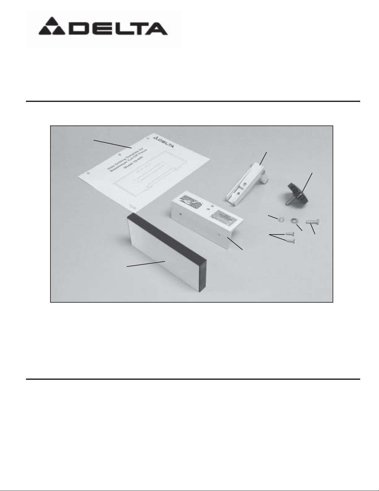
The cut-off fence is shipped complete in one container. Fig 1, illustrates all components shipped.
1
2
3
9
COMPONENTS
1. Drilling template (for Biesemeyer® fences only)
2. Clamp and bracket assembly
3. Knob assembly
4. 1/4-20 x 1” hex head bolt
5. 1/4” flat washer
SAFETY RULES
6
7
8
Fig. 1
6. 1/4-20 locknut
7. #10x 3/4” flat head self-tapping screw
8. 6” cut-off fence support
9. Cut-off fence board
5
4
1. DO NOT use cut-off fence in ripping applications; it is
only to be used with the miter gage to perform cut-offs.
2. ALWAYS make certain saw fence and cut-off fence are
securely fastened before use.
3. ALWAYS turn the saw off and allow the saw blade to
come to a complete stop before attempting to remove
cut-off pieces.
4. AVOID trapping the workpiece between the fence and
saw blade. The piece of wood being cut must be past the
cut-off fence before contacting the saw blade.
Page 2
ASSEMBLY
DISCONNECT SAW FROM POWER SOURCE UNTIL
ALL ASSEMBLY AND SET-UP PROCEDURES HAVE
BEEN COMPLETED.
FOR BIESEMEYER
FENCES ONLY.
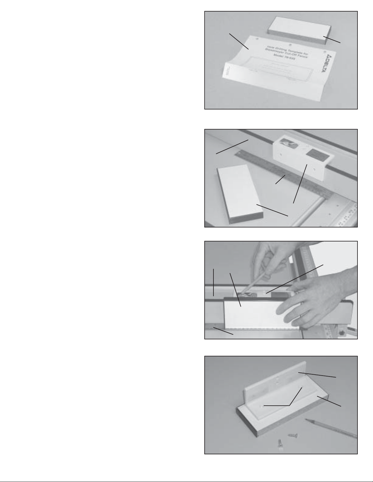
1. Fold template (A) Fig. 2, on fold line and align the
template with the bottom of fence board (B). Using a punch,
mark the fence board (B) as indicated on the template (A)
for Commercial or Home Shop installation. Then proceed
to section “FOR ALL FENCES” STEP 8.
FOR BRANDS OTHER THAN BIESEMEYER
2. Place cut-off support (C) Fig. 3, onto saw fence (D) as
shown.
3. Place a straight edge (E) Fig. 3, approximately
1/16”- 1/8” thick, onto saw table as shown. Then, place
cut-off fence board (F) Figs. 3 and 4, vertically onto straight
edge (E) and against saw fence (D) with the unfinished
edge down as shown in fig. 4.
4. Hold cut-off fence board (F) Fig. 4, Firmly against
cut-off fence support (C), and draw a line across the rear
of cut-off fence board (F) as shown.
®
COMMERCIAL OR HOME SHOP
A
B
Fig. 2
D
E
C
F
Fig. 3
5. Remove cut-off fence board (F) Fig. 4, and cut-off fence
support (C) from saw fence (D), and place cut-off fence
board onto a flat, supporting surface with pencil marks
facing up as shown in Fig. 5.
6. Align the top of cut-of f fence support (C) Fig. 5, with the
pencil line on cut-off fence board (F) and center cut-off
fence support (C) onto board.
7. Using a pencil, mark the back of cut-off fence board (F)
Fig. 5, through the two holes (G) in cut-off fence support
(C).
D
F
C
E
Fig. 4
C
FG
Fig. 5
2
Page 3
FOR ALL FENCES
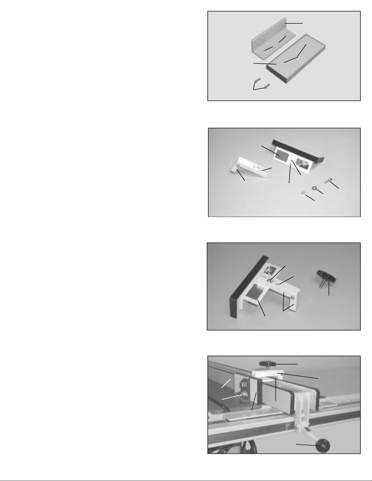
8. Using a 1/8” drill bit, drill two 1/8” pilot holes 1/2” deep at
the two marked locations on the back of cut-off fence board
(F) Figs. 5 and 6. NOTE: Mark the drill bit with masking
tape to act as a depth gage to prevent drilling through
fence board.
9. Align two holes (G) Fig. 6, with drilled holes (H) and
fasten cut-off fence support (C) to cut-off fence board (F)
using two #10 x 3/4” flat head screws (J).
10. Align hole (K) Fig. 7, in clamp and bracket assembly
(L) with the appropriate thru-hole (M) or (N) in cut-off fence
support (C) and fasten using the 1” long hex head bolt (P),
flat washer (R) and lockwasher (S). NOTE: Thru-hole (M)
Fig. 7, is used for Biesemeyer
fences which are approximately 4” wide, and thru-hole
(N) is used for Biesemeyer®home shop fences, or
fences that are approximately 3-1/2” wide. Also, bolt
(P) Fig. 7, is to be inserted from the bottom with the
flat washer (R) and lock nut (S) located on top.
CAUTION: Do not tighten lock nut (S) Fig. 7,
completely , for clamp and bracket assembly (L) Fig. 8,
needs to move freely.
®
commercial fences, or
C
G
F
H
J
Fig. 6
C
K
N
L
M
P
R
S
Fig. 7
11. Fig. 8 illustrates clamp and bracket assembly (L)
properly fastened to cut-off fence support (C), for use with
a Biesemeyer
®
commercial fence. Assembly to
Biesemeyer® home shop-style fences is similar.
12. Thread knob (T) into threaded hole (W) of clamp and
bracket assembly (L) approximately four complete turns.
13. Place entire cut-off fence assembly (X) Fig. 9, so it
straddles the saw fence (D) as shown, and tighten knob
(T) until cut-off fence assembly (X) is firmly clamped to
the saw fence (D). Then secure saw fence (D) in place by
pushing down on handle (H).
14. Using a square (Y) Fig. 9, determine if cut-off fence
board is 90 degrees to saw table. If an adjustment is
necessary, loosen knob (T) slightly and turn adjustment
screw (Z) accordingly. Then tighten knob (T) and recheck
squareness. Repeat adjustment if necessary.
S
W
T
L
C
Fig. 8
T
X
D
Y
Z
F
H
Fig. 9
3
Page 4

T
X
A
B
D
Fig. 10
SET -UP AND USE
DISCONNECT SAW FROM POWER SOURCE
1. Place entire cut-off fence (X) Fig. 10, so it straddles saw fence (D), and is positioned close to the front
edge of saw table as shown. Then tighten knob (T).
WARNING: ALWAYS POSITION CUT-OFF FENCE (X) FIG. 10, IN FRONT OF THE SAW BLADE SO
THE WORKPIECE CANNOT BE TRAPPED BETWEEN SAW FENCE AND SAW BLADE TO AVOID
KICKBACK. THE PIECE OF MATERIAL BEING CUT MUST BE PAST THE CUT-OFF FENCE (X)
BEFORE CONTACTING THE SAW BLADE.
2. Adjust and lock saw fence (D) Fig. 10, to the desired setting. NOTE: Cut-off fence assembly (X) is 1”
thick; therefore, you must add 1” when setting the saw fence to the desired cut.
3. Place edge of material to be cut (A) Fig. 10, against face of miter gage (B) and slide material until the
edge contacts cut-off fence (X) as shown.
4. Apply power to the saw.
Warning: ALWAYS turn the saw off and allow the saw blade to come to a complete stop before
attempting to remove cut-off pieces.
4
Page 5

REPLACEMENT P ARTS
78-939
CUT-OFF FENCE
REF.
NO. PART NUMBER DESCRIPTION
* 78-939 CUT-OFF FENCE, CONST OF:
1 1350066 KNOB ASSEMBLY
2 1352363 CLAMP
3 1350191 END CAP
4 1350303 1/4-20 X 1-1/2” HEX HD SCREW
5 1350295 1/4-20 X 1/2” HEX HD SCREW
6 1350077 FLAG DECAL
7 1350300 #10 X 4/4” FLAT HD SCREW
8 1350302 1/4-20 X 1” HEX HD SCREW
9 1350019 GLIDE PAD
10 1352361 SUPPORT
11 1352370 NAMEPLATE
12 1350280 1/4-20 LOCKNUT
13 1352364 BRACKET ASSEMBLY
14 1350312 1/4” FLAT WASHER
15 1350280 1/4-20 LOCKNUT
16 1352360 BOARD
* NOT SHOWN ASSEMBLED
5
Page 6

PARTS, SERVICE OR WARRANTY ASSISTANCE
To obtain additional information regarding this product or to obtain parts, service or warranty
assistance, please call or fax the following toll free number. Highly qualified and experienced
Customer Service Representatives are standing by to assist you.
Biesemeyer® Manufacturing
4825 Highway 45 North
Jackson, TN
38305
Phone Toll Free
(731) 660-5986 (800) 782-1831
Two Year Limited Warranty
Delta will repair or replace, at its expense and at its option, any Delta machine, machine part, or machine
accessory which in normal use has proven to be defective in workmanship or material, provided that the customer notifies his supplying distributor of the alleged defect within two years from the date of delivery to him, of
the product and provides Delta Machinery with reasonable opportunity to verify the defect by inspection. Delta
Machinery may require that electric motors be returned prepaid to the supplying ddistributoror authorized service center for inspection and repair or replacement. Delta Machinery will not be respponsible for any asserted
defect which has resulted from misuse, abuse or repair or alteration made or specificallyauthorized by anyone
other than an authorized Delta service facility, or representative. Under no circumstances will Delta Machinery
be liable for incidental or consequential damages resulting from defective products. This warranty is Delta
Machinery’s sole warrantyand sets forth the customers exclusive remedy to defective products;all other warranties, express or implied, whether of merchantability, fitness for purpose, or otherwise, are expressly disclaimed
by Delta.
6
Page 7

Cut Here
Model 78-939
Center marks for commercial fence holes
Biesemeyer Cut-Off Fence
Hole Drilling Template for
Center marks for home shop fence holes
Page 8

THIS PAGE INTENTIONALL Y LEFT BLANK\
 Loading...