

Page 1
®
T-Square
Universal
Home Shop
Fence System
®
P AR T NO. 1349943
DA TED 06-01-01
INSTRUCTION MANUAL
Page 2
INTRODUCTION
The models 78-930, 28” capacity; 78-931, 40” capacity; and 78-935, 52” capacity Universal T-Square® Fence Systems include the fence assembly , front rail, rear rail and front guide tube along with the necessary mounting hardware
for assembling the fence system to many different types and styles of table saws. An accessory right extension table,
must be ordered separately or a similar extension table must be constructed by following the instructions in this
manual. The accessory leg kit, model 78-951, used to support the extension table, must also be ordered separately.
IMPORTANT: The Biesemeyer® T-Square® Home Shop Fence System is designed to be used ONLY with a
supporting extension table and leg kit.
UNPACKING
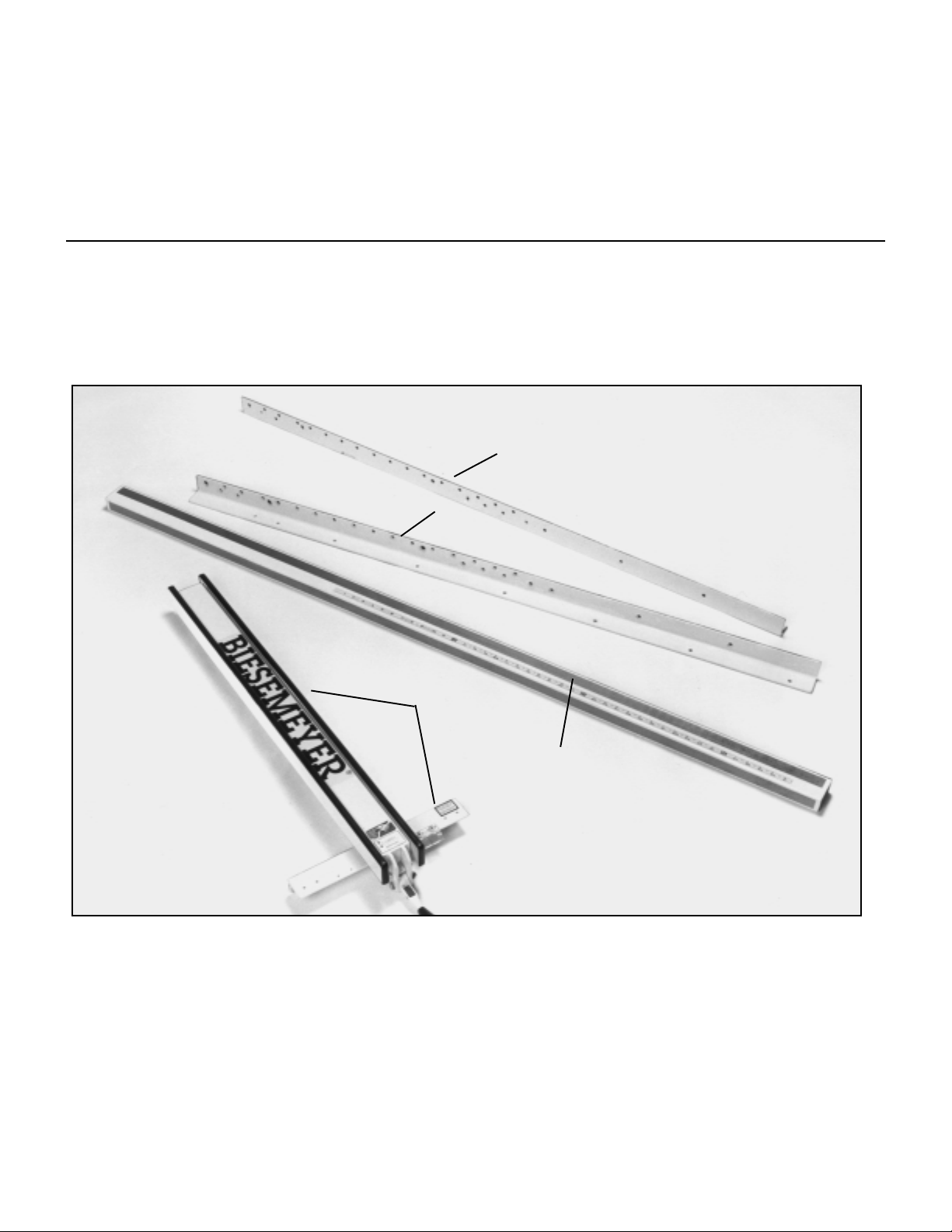
Carefully unpack the Biesemeyer® T-Square® Fence System from the shipping cartons. Figures 2 and 3 illustrate all
the items supplied with the Fence system.
1
2
4
3
Fig. 2
1 - Rear Rail
2 -Front Rail
3 - Guide Tube
4 - T-Square® Fence Assembly
2
Page 3
28
24
20
16
17
18
19
14
15
7*
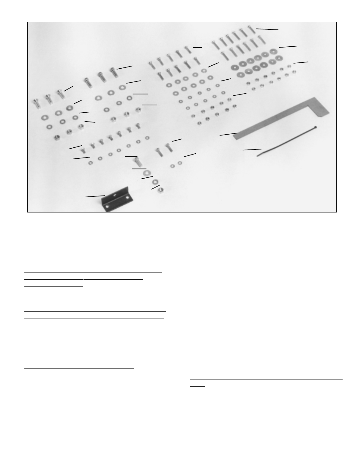
5 – Template for aligning front rail to saw table
6 – Cable Strap
7 -- *Switch bracket for use with Delta 10” Contractor’s
Saws and Delta 10” Contractor’s Saws II with plastic
switch actuator. See note below .
For Assembling Switch Bracket to Guide tube on
Delta 10” Contractor’s Saws and Delta 10”
Contractor’s Saws II.
8 – 1/4-20 x 3/4” long hex head screw (2)
9 – 1/4” lock washer (2)
For Assembling Switch to Switch Bracket on Delta
10” Contractor’s Saws and Delta 10” Contractor’s
Saws II
10 – 3/8-16 x 1” long hex screw
1 1 – 7/8” O.D. - 3/8 I.D. flat washer
12 – 3/8” lock washer
13 - 3/8-16 hex nut
For Fastening Guide T ube to Front Rail
14 – 1/4-20 x 1/2” long hex head screw (7)
15 – 1/4” lockwasher (7)
*NOTE: Current Delta saws no longer utilize the switch adapter bracket shown. If you are installing this system
on an older Delta saw that has the on/off switch shown in this manual, Please call Biesemeyer Manufacturing
Customer Service Department at 1-800-782-1831 to have a bracket sent to you at no charge.
10
21
22
23
8
9
11
12
13
Fig. 3
For Fastening Front Rail to Delta Saw Tables and
Sheet Metal Extension Wing if Applicable
16 – 3/8-16 x 1-1/4” long flat head screw (3)
17 – 7/8” O.D. - 3/8” I.D. flat washer (3)
18 – 3/8” lockwasher (3)
19 – 3/8-16 hex nut
For Fastening Rear Rail to Delta Saw T able and Sheet
Metal Wing if Applicable
20 – 3/8-24 x 1-1/2” hex head screw (3)
21 – 7/8” I.D. -3/8” I.D. flat washer (3)
22 – 3/8” lockwasher (3)
23 – 3/8-24 hex nut (3)
For Fastening Front and Rear Rails to Saw Table and
Extension Wings on Saws other than Delta
24 – 1/4-20 x 1-1/4” long hex head screw (10)
25 – Flat washer (10)
26 – 1/4” lockwasher (10)
27 – 1/4-20 hex nut (10)
For Fastening Front and Rear Rails to Right Extension
Table
28 – 1/4-20 x 1-1/2” long flat head screw (12)
29 – Flat washer (12)
30 – 1/4-20 hex nut (12)
25
26
27
5
6
29
30
3
Page 4
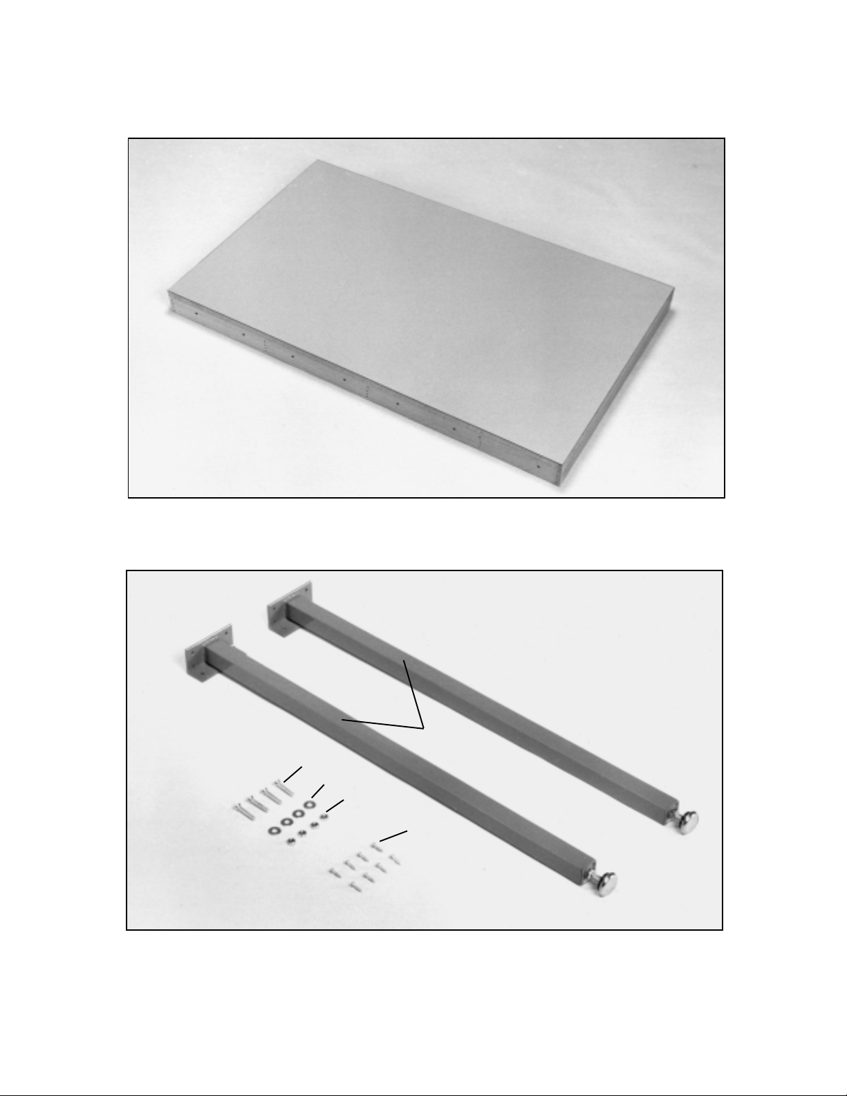
If you purchased the accessory right extension table, carefully unpack the extension table from the shipping container.
Figure 4 illustrates the accessory right extension table removed from the container. NOTE: If you did not purchase the
accessory right extension table for use with your T-Square® fence, or if your saw has a table depth other than 27”, refer to
the section of this manual titled ”CONSTRUCTING EXTENSION TABLE” for information on constructing a right extension table.
Fig. 4
If you purchased the accessory leg kit (model 78-951) for use with the right extension table, Fig. 5 illustrates the legs and
all loose items supplied with this accessory.
1
3
4
5
2
Fig. 5
1 - Leg (2) 4 - 1/4” flat washer (4)
2 - 5/8” long wood screws #8 (8) 5 - 1/4-20 hex nut (4)
3 - 1/4-20 X 1-1/2” long flat head Phillips screw (4)
4
Page 5
ASSEMBLY INSTRUCTIONS
When mounting the T-Square® Fence System to table saws that have been equipped with original equipment fence, guide
rails and open grate or stamped steel extension wings, remove the fence, front and rear guide rails and right extension
wing from the saw and assemble the T-Square® Fence as follows:
ASSEMBLING FRONT AND REAR RAILS
1. DISCONNECT THE SAW FROM THE POWER SOURCE
E
F
E
C
Fig. 6
FOR DEL TA SAWS ONLY
(Except Models 34-670, 36-380 and 36-600)
2. Align the two holes (E) Fig. 6, in the front rail (C) with the two through holes in the saw table and fasten the rail (C) to the
table saw using the two 3/8-16 x 1-1/4” long flat head screws, flat washers, lock washers and hex nuts supplied. Do not
completely tighten the mounting hardware at this time. It is not necessary to use clamps to hold the front rail to the saw
table. On Delta saws that are equipped with a sheet metal left extension wing, fasten the front rail (C) to the extension
wing using the remaining 3/8-16 x 1-1/4” long flat head screw, lock washer and hex nut supplied through hole (F) in the
front rail
D
NOTE: On Contractor’s saws made prior to 1988,
the two mounting holes in the front edge of the
saw were threaded. It is necessary to drill out the
threads with a 7/16” drill bit and use the hardware provided as indicated in step 2.
FOR ALL OTHER TABLE SAWS
(Including Delta Models 34-670, 36-380 and 36-600)
3. Raise saw blade (A) Fig. 7. Place a straight edge (B) against right side of saw blade extending out over front of saw
table as shown. Position front rail (C) against front edge of saw table and lightly clamp in place using bar clamps (D). Align
the notch (E) in front rail (C) with right side of saw blade using the straight edge (B) as shown, and tighten bar clamps (D).
4. Figure 7 illustrates the front rail (C) clamped to the front edge of the saw table.
A
B
D
E
C
Fig. 7
5
Page 6

FOR ALL SAWS
(Including Delta Models 34-67-, 34-380 and 36-600)
5. Using the template (G) Figures 8 and 9, check and
adjust front rail (C) at both sides of the saw table as shown,
to make sure rail (C) is level with table surface. THIS
MEASUREMENT IS CRITICAL. IF NECESSARY, ANOTHER P A TTERN CAN BE MADE USING THE DIMENSION FOUND IN FIG. 10. IMPORTANT: Template (G)
Figs. 8 and 9, must be on the saw table when checking,
not on extension wing.
FOR DELTA TABLE SA WS
(Except Models 34-670, 34-380 and 36-600)
6. When you are certain front rail (C) Figs. 8 and 9, is
level with the table surface, securely tighten front rail
mounting hardware.
FOR ALL OTHER SAWS
(Including Delta Models 34-670, 34-380 and 36-600)
7. When you are certain front rail (C) Figures 8 and 9, is
level with table surface, securely tighten bar clamps (D).
8. Check to make certain there is no interference such as
casting ribs behind front edge of saw table and drill a
minimum of four 1/4” through holes into the saw table
using holes in front rail as a template. Fasten front rail (C)
Fig. 11, to saw table using the four 1/4-20 x 1-1/4” long
flat head screws (H), flat washers, lockwashers and hex
nut supplied. Remove bar clamps after front rail is fastened to saw table.
9. Drill an additional through hole in the extension wing
using one of the holes in the front as a template and fasten front rail to extension wing using a 1/-20 x 1-1/4” long
flat head screw (J) Fig. 11, flat washer, lockwasher and
hex nut supplied.
G
C
D
Fig. 8
C
Fig. 9
USE PATTERN AS SHOWN HERE TO GAUGE DEPTH OF
FRONT RAIL. THIS MEASUREMENT IS CRITICAL.
PATTERN
SAW TABLE
FRONT RAIL
Fig. 10
D
D
2-3/16”
J
H
H
C
Fig. 1 16
Page 7

FOR DEL TA TABLE SA WS
(Except Models 34-670, 34-380 and 36-600)
10. Align the two non-countersunk hole (K) Fig. 12, of rear
rail (L) with the two holes in rear edge of saw table and
fasten rear rail to saw table as follows:
For Delta 10” Tilting Arbor Saws, 10”
Contractor’s Saws and 10” Contractor’s II –
Make certain the edge (M) Fig. 12, of the rail is
below miter gage slots an equal distance as shown
and fasten rear rail (L) to the saw using the two
3/8-24 x 1-1/4” long hex head screws, flat washers, lockwashers and hex nuts supplied.
IMPORTANT: DO NOT USE TEMPLATE SUPPLIED TO
LEVEL REAR RAIL.
FOR ALL OTHER T ABLE SAWS
(Including Delta Models 34-670, 34-380 and 36-600)
11. Clamp rear rail (L) Fig. 12, to back of saw table using
bar clamps, making certain left side of notch (N) in rail is
aligned with right side of saw blade as shown, using straight
edge (B). Also make sure edge (M) of rear rail is below
miter gage slots an equal distance as shown.
B
K
M
N
Fig. 12
H
K
L
H
J
IMPORTANT: DO NOT USE TEMPLATE SUPPLIED TO
LEVEL REAR RAIL.
12. Check to make certain there is no interference such as
casting ribs behind the rear edge of saw table and drill a
minimum of two 1/4” through holes through the saw table
using the holes in rear rail as a template. Fasten rear rail to
saw table using two 1/4-20 x 1-1/4” long flat head screws
(H) Fig. 13, flat washers, lockwashers and hex nuts supplied. Drill an additional through hole in the extension wing
using one of the holes in the rear rail as a template and
fasten rear rail to extension wing using a 1/4-20 x 1-1/4”
long flat head screw (J) Fig. 13, flat washer, lockwasher
and hex nut supplied. IMPORT ANT : If there is no room in
rear edge of table to drill through holes, it will be necessary
to drill #7 holes in table and tap holes using a 1/4-20 tap.
13. Figure 13 illustrates the bar clamp removed and the
rear rail (L) fastened to rear of the saw table and extension
wing using the hex head screws (H) and (J).
FOR ALL SAWS
14. After fastening the rear rail to the saw table, tilt saw
blade to make certain there is no interference between
the guard, splitter and rear rail. If there is, it will be necessary to enlarge the cutout area (P) Fig. 14, in the rear rail.
L
Fig. 13
P
Fig. 14
7
Page 8

Fig. 15
CONSTRUCTING EXTENSION TABLE
1. If you did not purchase the accessory right extension table for use with your T-Square® Fence,
construct an extension table by following the dimensions shown in Fig. 15.
ASSEMBLING ACCESSORY 78-951 LEG KIT
TO EXTENSION TABLE
A
1. Position the two legs (A) Fig. 16, at the two far corners
of the inside of one end of the extension table, as shown,
and mark the position of the eight holes (B) to be drilled
into the bottom of the table and the four holes (D) to be
drilled into the frame of the table. IMPORTANT: If your
saw and fence system will be used with a mobile base
underneath the saw and table legs, the position of the
legs may have to be changed to fit into the mobile base.
Remove the two legs (A) and using a 1/16” drill bit, drill
the eight holes 3/8” deep. Using a 1/4” drill bit, drill four
through holes through the end piece (C) Fig. 16, of the
table.
D
D
C
B
Fig. 16
8
B
Page 9

2. Replace the two legs and fasten to the bottom of the
table using the eight 5/8” long wood screws (B) supplied.
D
C
D
B
F
Fig. 17
3. Fasten the leg bracket (E) Fig. 18, to the end piece (C)
of the table using the two 1-1/2” long flat head Phillips
screws, flat washers and hex nuts (F) Figs. 17 and 18,
supplied. Fasten the remaining leg to the extension table
in the same manner.
C
F
E
Fig. 18
A
F
4. Figure 19 illustrates the two legs (A) assembled to the
bottom of the table.
9
Fig. 19
Page 10

ASSEMBLING TABLE ASSEMBLY TO FRONT AND REAR
RAILS
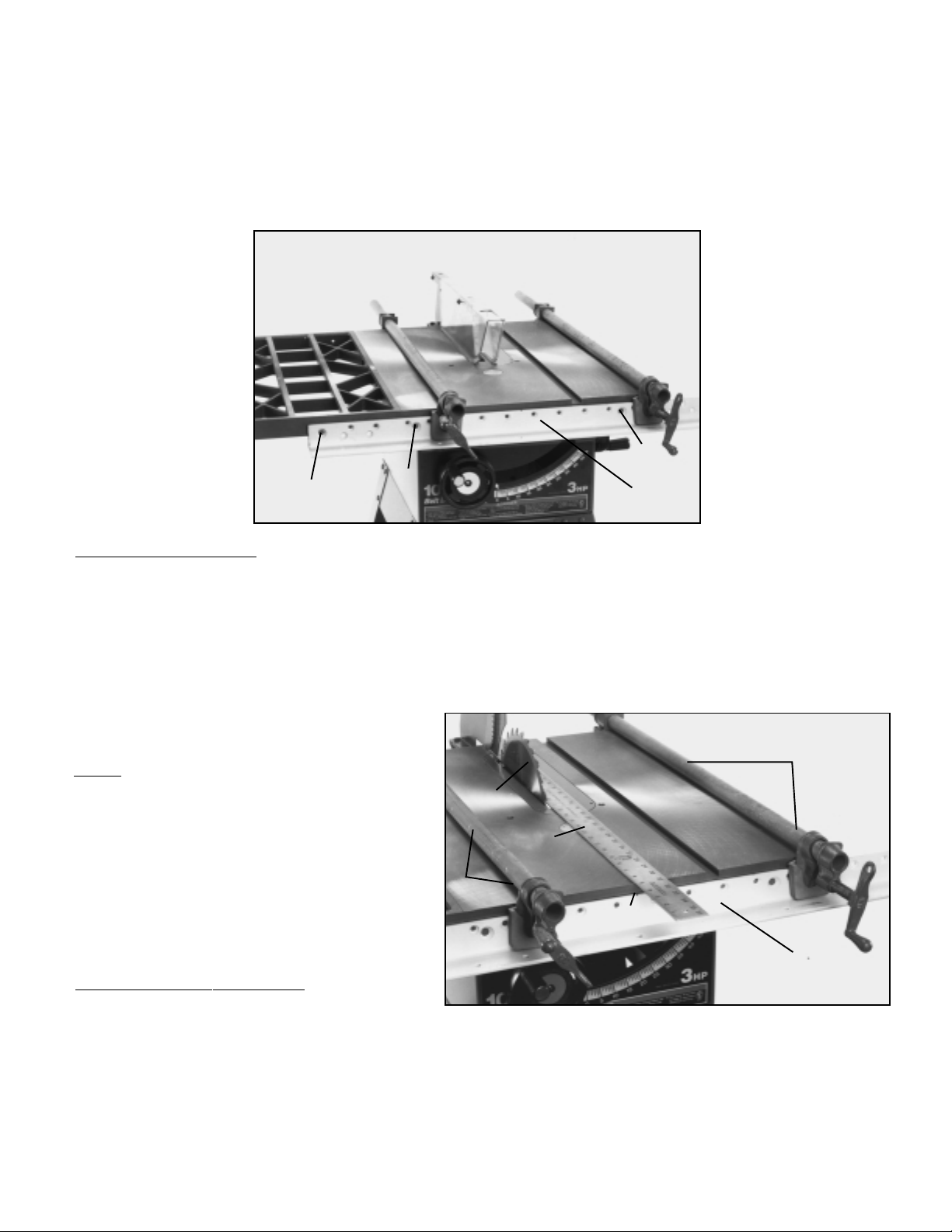
1. Place table assembly (A) in position between the front and rear rails, as shown in Figs. 20 and 21. Make sure end of
table (B) is flush against saw table (C) and using a bar clamp (D) snug up end of rails to hold table in position. Using a
straight edge (K) make certain table (A) in the same plane and level with saw table (C). Lightly tap table (A) up or down
and adjust leveling screws in bottom of legs to accomplish this. When you are certain table (A) Figs 20 and 21, is level and
in the same plane with saw table (C), tighten bar clamp (D) to hold everything in position. Then drill 1/4” through holes
through the front and rear of the extension table using the lower row of holes (E) in the front and rear rails as a template.
The number holes to be drilled will depend on the length of extension table.
C
B
A
K
E
D
Fig. 20
C
B
A
K
E
D
Fig. 21
10
Page 11

2. After the holes have been drilled in the front and rear
edges on the extension table, fasten both front and rear
rail to table using the 1-1/2” flat head Phillips screws (G)
Fig. 22, 1-1/4” O.D. flat washers (H) and hex nuts (J)
supplied.
Fig. 22
J
H
G
ASSEMBLING GUIDE TUBE TO FRONT RAIL
FOR ALL SAWS
1. Lay the guide tube (D) Fig. 23, on saw table as shown, and line up the threaded holes (M) on bottom of guide tube (D)
with the through holes (N) on the front rail (C). IMPORTANT: If a switch adapter is being used for Delta 10” Contractor’s
Saws to mount switch to rail and guide tube, holes (L) are used to mount the Contractor’s Saw switch adapter. On saws
other than Delta Contractor’s Saws, a special bracket must be constructed to permit mounting the switch to the bottom of
the front rail.
2. Lay the guide tube (D) Figs. 23 and 24, on the front rail and fasten the guide tube to the rail using the 1/2” long hex head
screws and lockwashers in all holes except the ones used to fasten the switch adapter, If applicable.
L
C
N
Fig. 23
M
D
M
N
D
Fig. 24
11
Page 12

FOR OLDER DELTA 10” CONTRACTOR’S SAWS AND
10” CONTRACTOR’S II SA WS ONLY
3. Assemble the Contractor’s Saws or Contractor’s Saw II
switch bracket (R) Fig. 25, to bottom of the front rail after
the guide tube is placed on rail using the two 3/4” long hex
head screws (S) and lockwashers. The screws (S) go
through the two holes in the switch bracket (R), through the
two holes in front rail and are threaded into the threaded
holes in bottom of guide tube.
4. The switch (O) Fig. 25, will then be assembled to the
switch bracket (R) as shown using the 1” long hex head
screw (P), flat washer and hex nut supplied.
P
S
R
O
S
FOR DEL TA SAWS ONLY
5. WARNING: If there is not enough cord when repositioning the switch, simply cut the cable strap holding the cord. After
the switch is repositioned, make certain that the cord does not come in contact with the saw blade at any angles from 90
to 45 degrees, and use the cable strap supplied with the fence to hold the cord in position.
Fig. 25
FENCE OPERATION
IMPORT ANT : Before operating fence, make sure the fence is adjusted parallel to the miter gage slot, as explained
later on in this manual.
A
1. T o move the fence along the guide rail, simply lift up clamp
lever (A) as shown in Fig. 26, slide fence to desired position
on guide, and push down on clamp lever (A) as shown in
Fig. 27, to lock fence in position. NOTE: A magnet (B) Fig.
27, is provided to hold clamp handle (A) in the up position
when moving the fence.
Fig. 26
12
B
A
Fig. 27
Page 13

2. The distance the fence is positioned away from the blade
is indicated by the witness line (C) Fig. 28, located in cursor
(D). If it is necessary to adjust the cursor (D), make a test
cut with the fence locked in position. Measure the width of
the finished cut and adjust the cursor (D) by loosening the
two screws (E), adjusting the cursor (D) until the witness
line (C) is aligned with the same marking on the scale as
the finished cut. Then tighten the two screws (E).
ADJUSTING FENCE PARALLEL TO
MITER GAGE SLOTS
E
D
C
Fig. 28
IMPORT ANT : Check to make certain that the miter gage
slots in the saw table are parallel with the saw blade
before adjusting the fence parallel to the miter gage
slots as follows:
The fence (A) Fig. 29, must be adjusted so it is parallel to
the miter gage slots (B). To check and adjust, move fence
(A) until the bottom edge of the fence is in line with the
edge of one of the miter gage slots as shown, and push
down on the fence clamping lever (C). Check to see if the
fence (A) is parallel to the miter gage slot the entire length
of the table. If an adjustment must be made, lift up fence
locking lever (C) and raise the fence up off the guide tube,
as shown in Fig. 30. Slightly tighten or loosen one of the
two adjusting screws (D) or (E) Fig. 30, using a 3/16” allen
wrench (F), not supplied. Replace the fence on the guide
tube and check again to see if the edge of the fence is
parallel with the miter gage slot the entire length of the slot.
Repeat this adjustment until you are sure the fence is parallel with the miter gage slot. IMPORT ANT: VERY LITTLE
MOVEMENT OF THE SCREWS (D) AND (E) FIG. 30, IS
NECESSARY TO ADJUST THE FENCE P ARALLEL WITH
THE MITER GAGE SLOT.
A
B
C
Fig. 29
E
D
F
13
Fig. 30
Page 14

ADJUSTING CLAMPING ACTION OF
FENCE LOCKING HANDLE
When the fence locking handle (A) is pushed to the down
position, as shown in Fig. 31, the fence assembly (B) should
be completely clamped to the guide tube (C). If the fence
assembly (B) is not completely clamped to the guide tube
(C) when the handle (A) is pushed down, as shown in Fig.
31, lift up handle (A) and raise fence assembly (B) up off the
guide tube (C). Slightly tighten the two adjusting screws (D)
and (E) Fig. 32, using the 3/16” allen wrench (F), not supplied. Screws (D) and (E) Fig. 32, should be tightened an
equal amount. Replace fence onto the guide tube and recheck to see if the fence assembly (B) Fig. 31, is completely
tightened to the guide tube (C) with the locking handle (A)
pushed down. Adjust further if necessary. IMPORTANT:
AFTER ADJUSTING THE CLAMPING ACTION OF THE
FENCE LOCKING HANDLE, CHECK TO SEE IF THE
FENCE IS P ARALLEL TO THE MITER GAGE SLOT AND
ADJUST IF NECESSARY.
Fig. 31
B
C
A
LUBRICATION
1. Apply paste wax to the fence and guide tube sliding surfaces weekly . Also, saw table and extension table surfaces
should be waxed often.
2. Apply grease to cam lock (A) Fig. 33, and camfoot (B)
occasionally to prevent wear.
14
E
D
F
Fig. 32
A
B
Fig. 33
Page 15

PARTS, SERVICE, OR W ARRANTY ASSISTANCE
To obtain additional information regarding this product or to obtain parts, service or warranty assistance, please fax or call the following toll free number. Highly qualified and experienced Customer
Service Representatives are standing by to assist you in weekdays from 7:30 AM to 4:00 PM Mountain Standard Time.
Biesemeyer
®
216 S Alma School Rd, Ste. 3
Mesa, AZ 85210
Phone Toll Free Fax
(480) 835-9300 (800) 782-1831 (480) 834-8515
Two Year Limited Warranty
Delta Machinery
Delta will repair or replace, at its expense and at its option, any Delta machine part, or machine
accessory which in normal use has proven to be defective in workmanship or material, provided that
the customer notifies his supplying distributor of the alleged defect within two years from the date of
delivery to him, of the product and provides Delta Machinery with reasonable opportunity to verify the
defect by inspection. Delta Machinery may require that electrical motors be returned prepaid to the
supplying distributor or authorized service center for inspection and repair or replacement. Delta machinery will not be responsible for any asserted defect which has resulted from misuse, abuse or repair
or alteration made or specifically authorized by anyone other than an authorized Delta service facility
or representative. Under no circumstances will Delta Machinery be liable for incidental or consequential damages resulting from defective products. This warranty is Delta’s sole warranty and sets forth
the customers exclusive remedy , with respect to defective products; all other warranties, expressed or
implied, whether of merchantability, fitness for purpose, or otherwise, are expressly disclaimed by
Delta.
15
 Loading...