

Page 1
INSTRUCTION MANUAL
D AT E D 3-5-96 PA RT NO. 1349984
'Delta International Machinery Corp. 1996
Biesemeyer
fi
T-SquarefiCommercial Fence Systems
50 C a pacity (Model 78-904)
30 C a pacity (Model 78-907)
Page 2

INTRODUCTION
The 50 capacity (model 78-904) and 30 cap acity (model 78-907) BiesemeyerfiT-Square
fi
Commercial fence systems are specially designed to be used with:
Delt a 10 T ilting Arbor Unisaws
fi
Delt a 10 T ilting Arbor Saws
Delt a 10 Contractor sfiSaws
Delt a 10 Contractor sfiSaws II
The T-SquarefiCommercial Fence Systems include the fence assembly, front rail, rear rail and
front guide tube. The accessory right extension t able (78-925 for 50 cap acity model and 78-927
for 30 c a p acity model) must be ordered separately or a similar extension t able must be con structed by following instructions in this manual. The accessory leg kit (model 78-952), used
to support the extension t able, must also be ordered separately . IMPORTANT:The T-Square
fi
Fence System is designed to be used O N LY with a supporting extension t able.
The following instructions illustrate assembling the T-SquarefiCommercial Fence System to a
Delt a 10 T ilting Arbor Unisawfi. Instructions for assembling the fence system to Delt a 10 Tilting
Arbor Saws and 10 Contractor sfiSaws are identical unless otherwise noted.
UNPACKING
Carefully unp ack the T -Squarefifence system from the shipping carton(s). Figure 2 illustrates all
the items supplied with the 78-904 and 78-907 fence system.
1 - Rear Rail
2 - Front Rail
3 - Guide T ube
4 - T-Square
fi
Fence Assembly
5 - Switch Adapter for Unisaws
fi
6 - Switch Adapter for Contractor sfiSaws
7 - Cable Strap
8 - T emplate for aligning front rail to saw t able
for fastening front and rear rails to
right extension t able
9 - 1-1/2 long flat head Phillip s screws (14)
10 - 1-1/4 O.D. Flat W ashers (14)
11 - 1/4-20 hex nut s (14)
for fastening rear rail to saw t able and sheet met al
extension wing if applicable
12 - 3/8-24 x 1-1/4 long hex head cap screws (3)
13 - 7/8 O.D. flat washers (3)
14 - Lock washers (3)
15 - 3/8-24 hex nut s (3)
for fastening front rail to saw t able and sheet metal
extension wing if applicable
16 - 3/8-16 x 1-1/4 long flat head Phillip s screws (3)
17 - 7/8 O.D. flat washers (3)
18 - Lock washers (3)
19 - 3/8-16 hex nut s (3)
for fastening guide tube to front rail
20 - 1/2 long hex screws (7)
21 - Lock washers (7)
for fastening on-off switch adapter to guide tube where
applicable on Unisawsfior ContractorsfiSaws
22 - 3/4 long hex head screws (2)
23 - Lock washers (2)
for fastening on-off switch to switch adapter where
applicable on Contractor sfiSaws
24 - 3/8-16 x 1 long hex head screw (1)
25 - 7/8 O.D. Flat washer (1)
27 - Hex nut (1)
Page 3
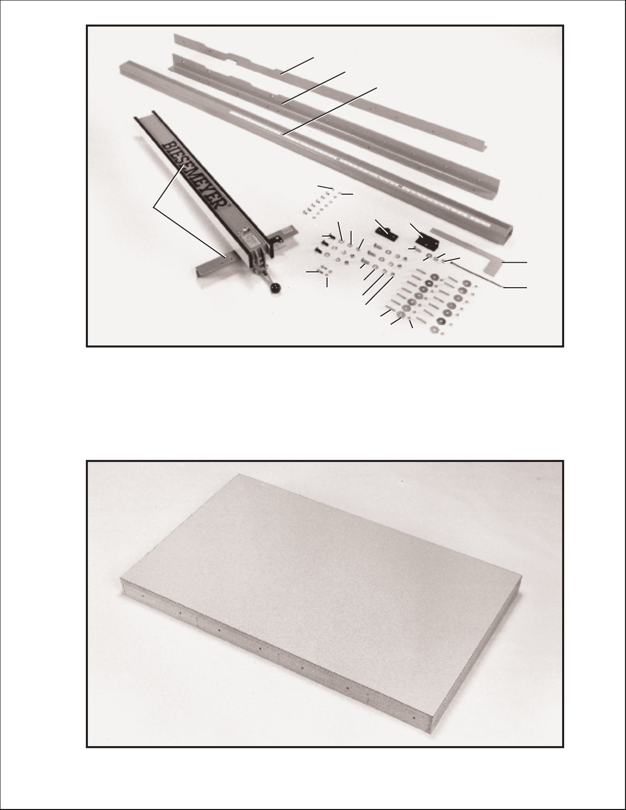
If you purchased the accessory right extension t able (model 78-925 for 50 cap acity fence or model
78-927 for 30 cap acity fence) carefully unp ack the extension t able from the shipping cont ainer . Figure
3 illustrates the right extension t able removed from the cont ainer . NOTE: If you did not purchase the
accessory right extension t able for use with your T -Squarefifence, refer to the ASSEMBLY INSTRUCTION section of this manual for information on constructing a right extension t able.
Fig. 2
Fig. 3
7
1
8
2
27
3
6
5
11
10
26
9
20
21
24
25
16
17
22
23
18
19
12
13
14
15
4
Page 4
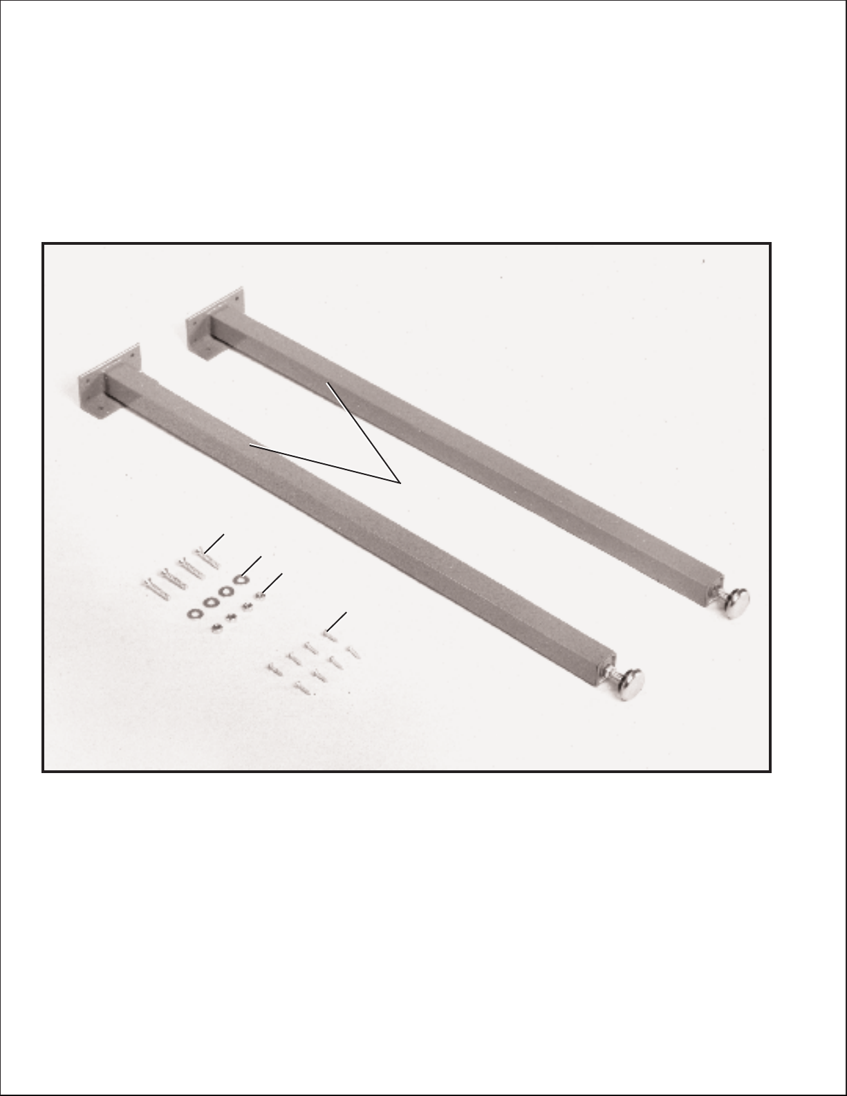
Fig. 4
If you purchased the accessory leg kit (model 78-952) for use with the right
extension t able, Figure 4 illustrates the legs and loose items supplied with
this accessory.
1 - Legs (2)
2 - 5/8 long wood screws #8 (8)
3 - 1/4-20 x 1-1/2 long flat head Phillip s screws (4)
4 - 1/4 flat washers (4)
5 - 1/4-20 hex nut s (4)
ASSEMBLY INSTRUCTIONS
When retrofitting the T -SquarefiFence System to t able saws that have been
equipped with original equipment fence, guide rails and extension wings, remove
the fence, front and rear guide rails and right hand extension wing from the saw.
If you purchased the saw and T -Squarefifence system as a promotional item,
assemble the saw as explained in the machine instruction manual and proceed to
assemble the T -Squarefifence to the saw as follows:
1. DISCONNECT THE S AW FROMTHEPOWER SOURCE.
3
4
5
2
1
Page 5

Fig. 5
Fig. 6
Fig. 7
Fig. 8
2. Assemble the front rail (A) Fig. 5, to front of saw t able
using the two 3/8-16 x 1-1/4 long flat head Phillip s
screws (B), 7/8 flat washers, lock washers and 3/8-16
hex nut s supplied. Screws (B) are inserted through the
two holes in the front rail, as shown and through the two
through holes in the front of the saw t able and fastened
to the t able with the flat washers, lockwashers and hex
nut s. IMPORTANT:Do not completely tighten front
rail mounting hardware at this time.
3. Using the template (D) Figures 6 and 7, check and
adjust front rail at both ends of the saw t able as shown,
to make sure rail (A) is level with t able surface and
tighten rail mounting hardware (B). IMPORTANT:
Template (D) must be on saw table when checking,
not on extension wing.
4. Assemble rear rail (E) Fig. 8, to rear of saw t able
using the two 3/8-24 x 1-1/4 long hex head screws (F),
7/8 flat washers and lockwashers as shown. NOTE:
When mounting fence to Unisaws, the two screws (F) are
threaded into the threaded holes in the saw t able, as
shown. When mounting fence to 10 Tilting Arbor Saws
or 10 Contractor s Saws, through holes are provided
instead of threaded holes on the rear edge of the saw
table. In this case the rear rail (E) is fastened to the t able
with the two hex head screws (F) and the flat washers,
lockwashers and hex nut s will be inside the rear ledge of
the saw t able.
5 Make certain top edge of rail (E) Fig. 8 is below t able
surface and that top edge of cut-out s (G) are below miter
gage slot s before tightening screws (F).
6.If the t able saw is equipped with a lef t hand sheet
metal extension wing, fasten the front rail (A) Fig. 7, to
the sheet met al extension wing with the 1-1/4 long flat
head Phillip s screw through hole (C) Fig. 7, in the front
rail and through the slot in the sheet metal extension
wing. Fasten the rear rail (E) Fig. 8, to the sheet metal
extension wing with the 1-1/4 long hex head screw
through hole (H) Fig. 8, in the rear rail and through the
slot in the sheet metal extension wing. Fasten both the
front and rear rails in place using the flat washers, lock
washers and hex nuts supplied.
A
B
A
B
D
C
A
B
D
E
F
G
G
F
H
Page 6

6
Fig. 9
Fig. 10
Fig. 1 1
8. Position the two legs (H) Fig. 10, at the two far corners
of the inside of one end of the extension t able, as shown,
and mark the position of the eight holes to be drilled into
the bottom of the t able. IMPORTA N T:If your saw and
fence system will be used with a mobile base under neath the saw base and table legs, the position of the
legs may have to be changed to fit onto the mobile
base. Remove the two legs (H) and using a 1/16 drill
bit, drill the eight holes 1/2 deep. Replace the two legs
and fasten to the bottom of the t able using the eight 3/4
long wood screws ( I) supplied.
9. Figure 11 illustrates one of the legs (H) fastened to
the bottom of the extension t able with the four wood
screws ( I). Using a 1/4 drill bit, drill two through holes
through the end piece (J) of the t able using the two holes
(K) as a template.
7. If you did not purchase the accessory right extension t able for use with your
T-Squarefifence, construct an extension t able by following the dimensions shown
in Fig. 9.
H
H
I
I
H
K
K
I
M
J
Page 7

Fig. 12
Fig. 13
Fig. 14
Fig. 15
10. Fasten the leg bracket (L) Fig. 12, to the end piece
(J) of the t able using the two 1-1/2 long flat head
Phillip s screws, flat washers and hex nuts (M) Figs. 1 1
and 12. Fasten the remaining leg to the extension t able
in the same manner.
11. Figure 13 illustrates the two legs (H) assembled to
the bottom of the t able.
12. Place t able assembly (N) Fig. 14, in position
between the two rails, as shown. Make sure end of t able
(O) is flush against saw t able (P) and using a bar clamp
(Q) snug up end of rails to hold t able in position. Using a
straight edge make sure t able (O) is in the same plane
and level with saw t able (P). Lightly t ap t able up or down
and adjust leveling screws (R) Fig. 15, in bottom of
legs to accomplish this. When you are cert ain t able (O)
Fig. 14, is level and in the same plane with saw t able (P),
tighten bar clamp (Q) to hold everything in position. Then
drill 1/4 through holes through the front and rear of the
extension t able using the holes (S) provided in rails as
template. NOTE: Number of holes (S) in the front and
rear rails will vary depending on the length of the rails
you purchased.
J
L
M
M
H
P
O
N
S
Q
R
Page 8

Fig. 17
Fig. 18 Fig. 19
16. Figure 19 illustrates the switch and nipple (W)
assembled to the switch adapter (X). The switch adapter
will be fastened to the front rail (A) and guide tube
through holes (Y) in the front rail af ter the guide tube is
fastened to the front rail (A).
15. Assemble the switch and nipple (W) Fig. 18, to switch
adapter for Unisaws (X) supplied with your T-Square fence.
14. If you are assembling the T-Squarefifence to a Delt a
Unisawfithat has the on-of f switch (W) Fig. 17, suspended
from the bottom of the saw t able, as shown, remove the
switch and nipple (W) from the bottom of the saw t able.
13. Af ter the holes have been drilled in the edge of the front and rear extension
table board, fasten both front and rear rail to t able using the 1-1/2 flat head
Phillip s screws (T) Fig. 16, 1-1/4 O.D. flat washers (U) and hex nuts (V).
Fig. 16
T
T
U
V
W
Z
X
W
Y
X
A
W
Page 9

Fig. 20
Fig. 21
Fig. 22
Fig. 23
17. Lay the guide tube (B) Fig. 20, on the saw t able as
shown, and line up the threaded holes (C) on bottom of
guide tube (B) with the through holes (D) on the front rail
(A). IMPORTAN T:If a switch adapter is being used for
Unisaws or 10 Contractor s Saws to mount the
switch to the rail and guide tube, holes (E) are used
to mount the Unisaw switch adapter and holes (F)
will be used for the Contractor s Saw switch adapter .
22. On the Contractor s S a w , att ach the switch (M)
Fig. 23, to the switch adapter (K) using the 1 long hex
screw (N), flat washer , lockwasher and hex nut supplied.
18. Position the guide tube (B) Figs. 21 and 22, on the
front rail and fasten the guide tube to the rail using the
1/2 long hex screws (G) and lockwashers in all of the
holes except the ones used to fasten the switch adapter
if applicable.
19. Figure 21 illustrates the Unisaw switch adapter (H)
mounted to the front rail and guide tube using two 3/4
long hex screws (J) and lockwashers.
20. Figure 22 illustrates the Contractor s Saw switch
adapter (K) mounted to the front rail guide tube using two
3/4 long hex screws (J) and lockwashers.
21. NOTE: If there is not enough cord (L) Figs. 21 and
22, available to pull out and reposition the switch, simply
cut the cable strap holding the cord to the inside of the
saw cabinet. After switch is repositioned, make cert ain
that the cord does not come into cont act with the saw
blade and use the cable clamp supplied with the fence to
hold the cord in position.
A
B
C
D
F
F
E
E
B
G
G
J
J
H
L
G
L
K
B
J
N
K
M
Page 10

Fig. 24
Fig. 25
Fig. 26
FENCE OPERATION
IMPORTANT: Before operating fence, make sure the fence is adjusted parallel to
the miter gage slot, as explained later on in this manua l.
1. To move the fence along the guide rail, simply lif t
up clamp lever (A) as shown in Fig. 24, slide fence to
desired position on rail, and push down on clamp lever
(A) as shown in Fig. 25, to lock fence in position. NOTE:
A magnet (E) Fig. 25, is provided to hold clamp handle
(A) Figs. 24 and 25, in the up position when moving the
fence.
2. The dist ance the fence is positioned away from the
blade is indicated by the witness line (B) Fig. 26, located
on the cursor (C). If it is necessary to adjust the cursor
(C), make a test cut with the fence locked in position.
Measure the width of the finished cut and adjust the
cursor (C) by loosening the two screws (D), adjusting the
cursor (C) until the witness line (B) is aligned with the
same marking on the scale as the finished cut. Then
tighten the two screws (D).
A
A
B
C
D
E
Page 11

Fig. 27
Fig. 28
Fig. 29
Fig. 30
ADJUSTING FENCE
PARALLEL TO
MITER GAGE SLOTS
NOTE: Delt a t able saws have been aligned at the factory
so that the miter gage slot s in the t able are p arallel with
the saw blade. It is recommended, however, to check
and make certain this alignment is correct before adjust ing the fence p arallel to the miter gage slot as follows:
The fence (A) Fig. 27, must be adjusted so it is p arallel to
the miter gage slot s (B). To check and adjust, move
fence (A) until the bottom edge of the fence is in line with
the edge of one of the miter gage slot s as shown, and
push down on the fence clamping lever (C). Check to see
if the fence (A) is p arallel to the miter gage slot the entire
length of the t able. If an adjustment must be made, lif t up
fence locking lever (C) and raise fence up of f the guide
tube, as shown in Fig. 28. Slightly tighten or loosen one
of the two adjusting screws (D) or (E) Fig. 28, using a
3/16 allen wrench (F), not supplied. Replace the fence
on the guide tube and check again to see if the edge of
the fence is p arallel with the miter gage slot the entire
length of the slot. Repeat this adjustment until you are
sure the fence is p arallel with the miter gage slot.
IMPORTANT:VERY LITTLE MOVEMENT OF SCREWS
(D) A N D (E) IS NECESSARY TO ADJUST THE
FENCE PARALLEL WITH THE MITER GAGESLOT.
ADJUSTING CLAMPING
ACTION O F FENCE
LOCKING HANDLE
When the fence locking handle (A) is pushed to the down
position, as shown in Fig. 29, the fence assembly (B)
should be completely clamped to the guide tube (C). If
the fence assembly (B) is not completely clamped to the
guide tube (C) when the handle (A) is pushed down, as
shown in Fig. 29, lif t up handle (A) and raise fence
assembly (B) up of f the guide tube (C). Slightly tighten
the two adjusting screws (D) and (E) Fig. 30, using the
3/16 allen wrench (F) not supplied. Adjusting screws
(D) and (E) Fig. 30, should be tightened an equal
amount. Replace fence onto the guide tube and recheck to see if the fence assembly (B) Fig. 29, is com pletely tightened to the guide tube (C) with the locking
handle (A) pushed down. Adjust further if necessary.
IMPORTANT:AFTER ADJUSTING THE CLAMPING
ACTION O F TH E FENCE LOCKING HANDLE, CHECK
TO SEE IF THE FENCE IS PARALLEL TO THE MITER
GAGESLOT AN D ADJUST IF NECESSARY.
A
C
B
E
F
D
A
C
B
F
D
E
Page 12

LUBRICATION
1. Apply paste wax to fence and guide tube sliding sur faces weekly. Also, saw t able and extension t able surface
should be waxed of ten.
2. Apply grease to cam lock (A) Fig. 31, and cam foot (B)
occasionally to prevent wear.
Fig. 31
Delt a will rep air or replace, at it s expense and at it s option, any Delt a machine, machine part, or machine
accessory which in normal use has proven to be defective in workmanship or material, provided that the
customer notifies his supplying distributor of the alleged defect within two years from the date of delivery
to him, of the product and provides Delt a Machinery with reasonable opportunity to verify the defect by
inspection. Delt a Machinery may require that electric motors be returned prep aid to the supplying dis tributor or authorized service center for inspection and rep air or replacement. Delta Machinery will not be
responsible for any asserted defect which has resulted from misuse, abuse or rep air or alteration made
or specifically authorized by anyone other than an authorized Delt a service facility or represent ative.
Under no circumst ances will Delta Machinery be liable for incident al or consequential damages resulting
from defective product s. This warranty is Delt a Machinery s sole warranty and set s forth the custome rs
exclusive remedy, with respect to defective products; all other warranties, express or implied, whether of
merchantability , fitness for purpose, or otherwise, are expressly disclaimed by Delt a.
Two Y ear Limited Warranty
Delt a Machinery
Printed in U.S.A.
PARTS, SERVICE OR WARRANTY ASSISTANCE
To obt ain additional information regarding this product or to obt ain p art s, service or warranty
assist ance, please call or fax the following toll free Hotline number . Highly qualified and
experienced Customer Service Representatives are st anding by to assist you on weekdays
from 7:00 A M to 5:00 PM Mountain S tandard T ime.
Biesemeyer
fi
a subsidiary of Delt a W oodworking Machinery
216 South Alma School Rd., Suite 3
Mesa, AZ 85210
Phone: Hotline: Fax:
(602) 835-9300 (800) 782-1831 (602) 834-8515
A
B
 Loading...