

Page 1
®
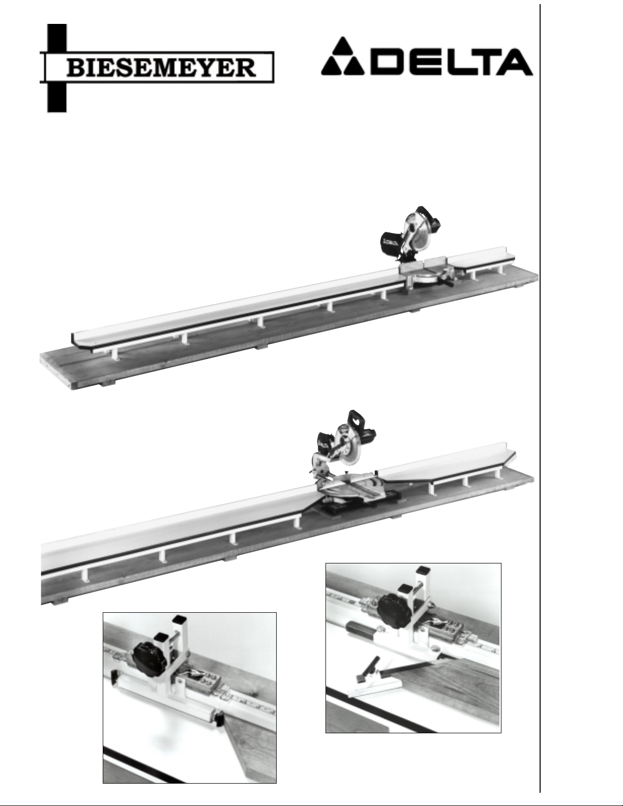
T-SQUARE® MITER SAW TABLES AND CUT-OFF STOPS
Miter Tables for 10” Saws (Models 78-802, 78-804, 78-806, 78-808)
Miter Tables for 12” and Slide Saws (Models 79-803, 79-804, 79-806, and 79-808)
Cut-Off Saw Stops ( Model 78-989, 78-990, 78-992, and 78-994)
Part No. 1351767
Dated 5-1-2001
INSTRUCTION MANUAL
Page 2

INTRODUCTION
Biesemeyer® T-Square® Miter Tables and Saw Stops are designed to fit all miter saws and used in conjunction with the
adhesive backed measuring tapes that read right-to-left (left hand) and left-to-right (right-hand). Tapes are available in
English or Metric/English combination. The use of the stops along with the accessory tables and measuring tapes eliminate the need for cumbersome C-clamps and hand-held measuring tapes, and will make any motorized miter saw more
accurate, more productive and more economical to use. The following instructions explain the assembly procedure when
using the table system with a Delta miter or slide saw and these instructions are the same for other brands and models of
miter and slide saws.
SEPATGNIRUSAEMDEKCAB-EVISEHDA
.oNledoMhtgneLhtdiWepyT
*650-97toof21hcni2/1hsilgnE/cirteM,dnahthgiR
*750-97toof21hcni2/1hsilgnE/cirteM,dnaHtfeL
160-97toof21hcni2/1hsilgnE,dnaHthgiR
260-97toof21hcni2/1hsilgnE,dnaHtfeL
*460-97toof21hcni4/3hsilgnE/cirteM,dnaHthgiR
560-97toof21hcni4/3hsilgnE,dnaHthgiR
*760-97toof6hcni4/3hsilgnE/cirteM,dnaHthgiR
660-97toof21hcni4/3hsilgnE,dnaHtfeL
860-97toof6hcni4/3hsilgnE,dnaHthgiR
960-97toof6hcni2/1hsilgnE,dnaHthgiR
070-97toof6hcni2/1hsilgnE,dnaHtfeL
*170-97toof6hcni2/1cirteM/hsilgnE,dnaHtfeL
* Metric/English tapes are not compatible with the Inside Miter Cutoff Saw Stop or the Inside Miter Cutoff Stop.
ASSEMBLY INSTRUCTIONS
1. Place the saw tables, one of which is shown at (A) Fig. 2,
on a workbench or other suitable flat surface.
2. Position the miter saw (B) Fig. 2, next to the miter table as
shown, and using a combination square (C), measure the
distance the saw table is below the surface of the miter table.
NOTE: If the saw table is higher than the surface of the miter
table, the miter tables will have to be raised to the same level
as the saw table in the same manner.
A
C
B
3. Plane a piece or pieces of hardwood stock (D) Fig. 2, to
the same thickness that the saw is below the miter table surface. This is the distance which was determined in STEP 2.
D
Fig. 2
2
Page 3
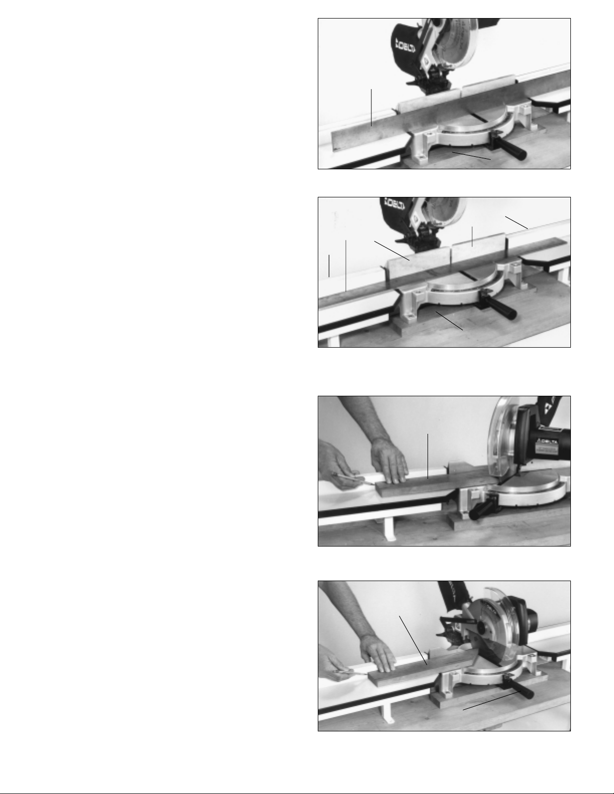
4. Mount the miter saw to the planned stock (D) Fig. 3, and
using a straight edge (E), make certain the saw table surface is level with the miter table surface, as shown in Fig. 3,
and that the saw fence (F) is in line with the fence (A) of the
miter tables, as shown in fig. 4
5. IMPORTANT: If you are attaching a scale to the top
of the miter table fence, it is important to determine if
the miter saw is a center pivot saw in order to accurately use the scale. This can be done as follows
E
D
Fig. 3
A
F
E
A
F
6. Cut a piece of stock (G) Fig. 5, at the 45 degree left miter
angle and without moving the work piece, make a mark on
the miter table fence at the end of the work piece, as shown.
7. Move the miter arm (P) to the 90 degree straight cut-off
position, as shown in Fig. 6, and slide the workpiece (G)
until it contacts the saw blade teeth. If the stock does not
change position, you have a center pivot saw which can be
fastened to the top of the workbench with the saw fence in
line with the miter table fence. If the workpiece did move,
make a second mark on the miter table fence at the end of
the workpiece at its new position, as shown.
D
Fig. 4
G
Fig. 5
G
3
P
Fig. 6
Page 4
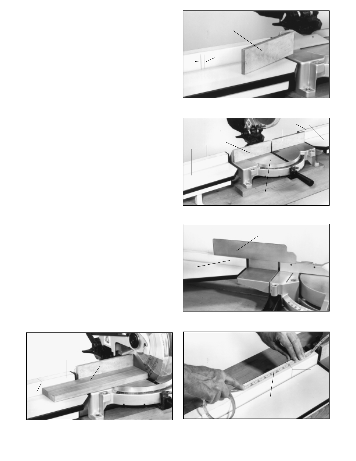
8. Measure the distance between the two marks (H) Fig. 7,
and plane a piece of stock to this dimension. The height and
length of the stock should be the same size as the miter saw
fence.
9. Fig. 7 illustrates the piece of stock (J) which will be fastened to the left miter fence.
10. Fig. 8 illustrates both the left and right fence halves (J)
fastened to the saw fence. These fence halves were fabricated in STEP 8.
11. Fasten the miter saw (K) and miter tables (L) Fig. 8, to
the workbench or other suitable flat surface, making certain
that the saw table surface (K) is level with the miter table
surface (L), and that the saw fence (J) is in line with the miter
table fence.
J
H
H
Fig. 7
M
J
L
12. IMPORTANT: If the miter saw you are using is
equipped with a sliding fence, the sliding fence (N) Fig.
9, must either be removed or modified so that it will slide
over the top of the miter table fence (M).
T APE INSTALLATION
1. Make a 90 Degree straight cut-off on a workpiece (H) Fig.
10, as shown. Make certain that the workpiece (H) extends
over onto the miter table (J). Without moving the workpiece
(H), make a mark (K) on the miter table fence at the end of
the workpiece. Extend the mark (K) to the top of the miter
table fence as shown.
2. Measure the length of the cut-off workpiece (H) Fig. 10.
Line up the mark on the measuring tape with the mark (K)
Fig.1 1 on the miter table fence that corresponds to the length
of the cut-off workpiece. In this case, the length is 14 inches.
3. Trim the ends of the tape to the desired length and remove the backing from the tape. Carefully install tape (L)
Fig. 11, to the top center of the miter table fence, lining up
the marks determined in STEP 2.
M
L
M
J
K
Fig. 8
N
4. Use a roller to press the tape securely to the surface.
J
H
K
Fig. 10 Fig. 1 1
Fig. 9
K
L
4
Page 5

78-989 DUAL POINTER
CUT-OFF STOP
The 78-989 Dual Pointer Cut-Off Stop, shown in Fig. 12,
gives precise settings to 1/64th of an inch. An adjustable
stop screw (C) positively limits the workpiece (D), as shown,
and should be adjusted to the scale and cursor (A). The
dual pointer cut-off stop can be used on the right hand side
of the saw blade by using the cursor (E) and stop screw
(F).
78-990 DUAL POINTER OUT-
SIDE/CUT-OFF MITER STOP
The 78-990 Dual Pointer Outside/Cut-Off Miter Stop is designed to act as a positive stop for 90 degree cut-off
workpieces, as shown in Fig. 13, or 45 degree outside
workpieces, as shown in Fig. 14. The stop (B) is adjustable by loosening locknut (A) Figs. 13 and 14, adjusting
the stop (B), and tightening locknut (A). Cursor (C) Figs.
13 and 14, is provided for 90 degree square cuts and cursor (D) is used for 45 degree miter cuts. The cursors (C)
and (D) are adjustable by loosening screws (E), adjusting
the cursor and tightening the screws. This stop is designed
to be used on either side of the saw blade, as an extra set
of cursors and stop are provided on the opposite end of
the miter stop.
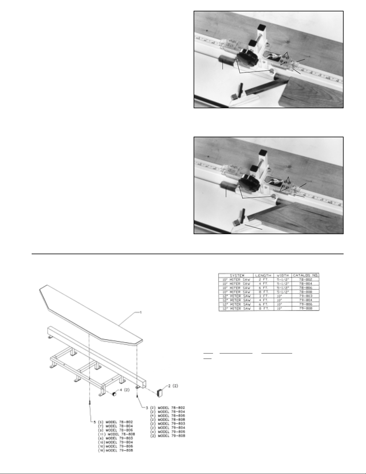
78-992 DUAL POINTER FLIP
A
E
C
F
Fig. 12
E
D
E
A
B
Fig. 13
D
C
STOP
The 78-992 Dual Pointer Flip-Stop is used mainly when
making repetitive cutting operations, as shown in Fig. 15,
and then flipped up out of the way with lever (A) when not
in use. For more convenience, the Flip-Stop can be used
with two or more stops as shown at (B) and (E) Fig. 16,
and positioned as close as 4-1/2 inches apart anywhere
along the fence for making multiple, often used repetitive
cuts without having to remeasure. Fig. 16 illustrates lever
(A) flipped up out of the way and stop (B) used to position
the workpiece. An adjustable stop screw (D) Fig. 15, positively limits the workpiece, as shown, and should be adjusted to the scale and cursor (C). The cursor (C) Fig. 15,
is supplied on each side of the stop, enabling you to use
the stop on either side of the saw blade.
C
C
D
E
D
C
E
A
B
Fig. 14
E
B
A
Fig. 15
A
Fig. 16
5
Page 6
78-994 DUAL POINTER IN-
SIDE/CUT-OFF MITER STOP
F
E
The 78-994 Dual Pointer Inside/Cut-off Miter Stop is designed to act as a positive stop for 90 degree cut-off
workpieces, as shown in Fig. 17, or 45 degree inside miter
angles, as shown in Fig. 18. The outside edge of the 45
degree miter angle is suppported by the adjustable stop
block (C), as shown in Fig. 18. The stop can be used on
either the right or left side of the saw blade as the stop bar
(B) can be removed and inserted into the other end of the
bracket by loosening the two screws (A) Figs. 17 and 18,
Removing stop bar (B) and inserting stop bar into opposite
end of bracket, making sure indent in stop bar is engaged
with end of screw (A). Cursor (D) Figs. 17 and 18, is used
for straight 90 degree cuts and cursor (E) is used when
cutting 45 degree miter angles. The cursors (D) and (E)
are adjustable by loosening screws (F), adjusting cursors
(D) and (E) , and tightening screws (F).
B
A
F
D
Fig. 17
F
E
B
A
F
D
C
Fig. 18
REPLACEMENT PARTS
MITER SA W TABLE
78-802, 78-804, 78-806, 78-808
79-803, 79-804, 79-806, 79-808
REF. PART NUMBER DESCRIPTION
NO.
* OPTIONAL MITER SAW TABLE ASSY,
1 1351825 TABLE (5-1/2” x 2’)
1 1351826 TABLE (5-1/2” x 4’)
1 1351827 TABLE (5-1/2” x 6’)
1 1351828 TABLE (5-1/2” x 8’)
1 1351861 TABLE (10” x 3’)
1 1351862 TABLE (10” x 4’)
1 1351863 TABLE (10” x 6’)
1 1351864 TABLE (10” x 8’)
2 1351823 END CAP
3 1350441 #10 X 5/8” PH PN HD SCREW
4 1351824 END CAP
5 1351911 #10 X 1-1/2” PAN HD SCREW
* NOT SHOWN ASSEMBLED
INCL:
6
Page 7
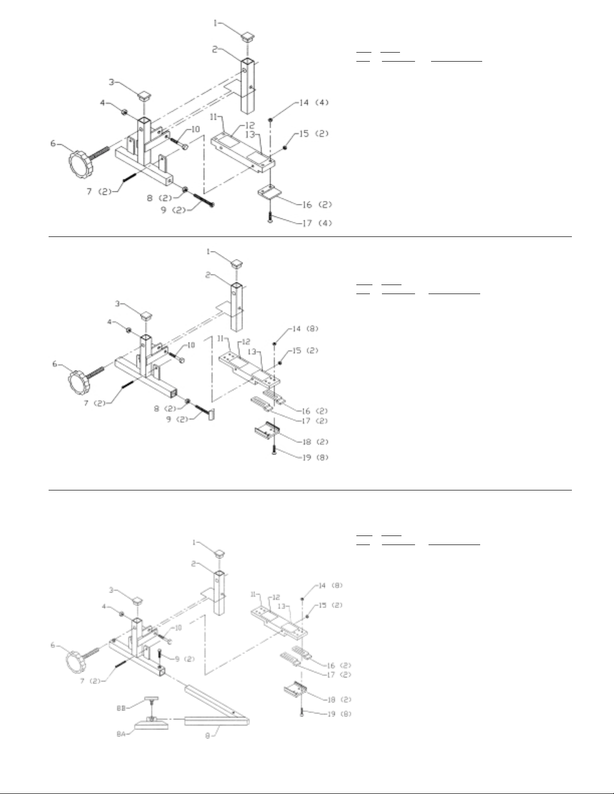
78-989
DUAL POINTER CUTOFF SA W STOP
REF PART
NO. NUMBER DESCRIPTION
* 78-989 DUAL POINTER CUTOFF SAW STOP,
1 1350191 END CAP
2 1350192 CLAMP BAR
3 1350191 END CAP
4 1350280 1/4-20 LOCK NUT
6 1350188 KNOB
7 1350408 #10-32 X 1-3/4" PAN HD SCR
8 1350409 5/16-18 HEX NUT
9 1350410 5/16-18 X 2” FLAT HD SCR
10 1350303 1/4-20 X 1-1/2” HEX HD SCR
11 1351312 SLIDE BLOCK
12 1350207 NAMEPLATE
13 1350077 FLAG DECAL
14 1350315 #10-32 HEX NUT
15 1350315 #10-32 HEX NUT
16 1350189 CURSOR
17 1350411 #10-32 X 7/8” FLAT HD SCR
* NOT SHOWN ASSEMBLED
INCL:
78-990
DUAL POINTER OUTSIDE MITER
CUTOFF SA W STOP
REF. PART
NO. NUMBER DESCRIPTION
* 78-990 DUAL POINTER OUTSIDE MITER
CUTOFFSAW STOP
1 1350191 END CAP
2 1350192 CLAMP BAR
3 1350191 END CAP
4 1350280 1/4-20 LOCK NUT
6 1350188 KNOB ASSY
7 1350408 #10-32 X 1-3/4” PAN HD SCREW
8 1350409 5/16-18 HEX NUT
9 1350980 FOOT ASSY
10 1350303 1/4-20 X 1-1/2” HEX HD SCREW
11 1351315 SLIDE BLOCK
12 1350207 NAMEPLATE
13 1350077 FLAG DECAL
14 1350698 #08-32 HEX NUT
15 1350315 #10-32 HEX NUT
16 1350694 CURSOR (RED)
17 1350696 CURSOR (BLACK)
18 1350693 CURSOR CLAMP
19 1350697 #08-32 X 7/8" FLAT HD SCREW
* NOT SHOWN ASSEMBLED
, INCL:
78-994
DUAL POINTER INSIDE MITER
CUTOFF SAW STOP
REF. PART
NO. NUMBER DESCRIPTION
* 78-994 DUAL POINTER INSIDE MITER CUTOFF
1 1350191 END CAP
2 1350192 CLAMP BAR
3 1350191 END CAP
4 1350280 1/4-20 LOCK NUT
6 1350188 KNOB ASSY
7 1350408 #10-32 X 1-3/4” PAN HD SCREW
8 1352139 SLIDE BAR
8A 1350975 INSIDE MITER STOP
8B 1350809 WING SCREW
9 1350295 1/4-20 X 1/2” HEX HD SCREW
10 1350303 1/4-20 X 1-1/2” HEX HD SCREW
11 1351315 SLIDE BLOCK
12 1350207 NAMEPLATE
13 1350077 FLAG DECAL
14 1350698 #08-32 HEX NUT
15 1350315 #10-32 HEX NUT
16 1350694 CURSOR (RED)
17 1350696 CURSOR (BLACK)
18 1350693 CURSOR CLAMP
19 1350697 #08-32 X 7/8” FLAT HD SCREW
* NOT SHOWN ASSEMBLED
SAW STOP
, INCL:
7
Page 8

78-992
DUAL POINTER FLIP-STOP
REF. PART
NO. NUMBER DESCRIPTION
* 78-992 DUAL POINTER FLIP-STOP,
1 1350191 END CAP
2 1350280 1/4-20 LOCK NUT
3 1350413 #10-32 X 1-1/4" HEX SOC SET SCREW
4 1350408 #10-32 X 1-3/4” PAN HD SCREW
5 1350212 FLIP ASSY
6 1350203 KNOB
7 1350409 5/16-18 HEX NUT
8 1360412 5/16-18 X 1-1/2” FLAT HD SCREW
9 1350414 5/16-18 X 1-1/4” HEX HD SCREW
10 1350308 5/16" FLATWASHER
11 1350411 #10-32 X 7/8” FLAT HD SCREW
12 1350189 CURSOR
13 1350315 #10-32 HEX NUT
14 1350315 #10-32 HEX NUT
15 1350206 NAMEPLATE
16 1351318 SLIDEBLOCK
17 1350303 1/4-20 X 1-1/2” HEX HD SCREW
18 1350202 CLAMP ASSY
19 1350066 KNOB ASSY
* NOT SHOWN ASSEMBLED
INCL:
PARTS, SERVICE OR WARRANTY ASSISTANCE
This product is manufactured to high quality standards and is serviced by a network of
Factory Service centers and Authorized Service Stations.
To obtain additional information regarding this product, or to obtain parts, service or
warranty assistance, please call our toll-free numbers. Highly qualified and experienced
Customer Service Representatives are standing by to assist you.
PORTER CABLE/DELTA
4825 HWY 45 N
Jackson, TN 38302
Toll Free:
(800) 223-7278
Hours:
BIESEMEYER
216 South Alma School Rd.
Suite 3
Mesa, AZ 85210
Toll Free:
(800) 782-1831
®
Weekdays
7:00 AM to 5:00 PM
Central Standard Time
E-Mail:
mail@biesemeyer.com
Hours:
Weekdays
7:30 AM to 4:00 PM
Mountain Standard Time
 Loading...