

Page 1

3 Speed digital ambient
air Cleaner
Système numérique de filtration
de l’air ambiant à 3 vitesses
Purificador digital de aire ambiental
de 3 velocidades
Français (12)
Español (22)
www.DeltaMachinery.com
Instruction manual
Manuel d’utilisation
Manual de instrucciones
INSTRUCTIVO DE OPERACIÓN, CENTROS
DE SERVICIO Y PÓLIZA DE GARANTÍA.
LÉASE ESTE INSTRUCTIVO
ANTES DE USAR EL PRODUCTO.
50-871
Page 2
TABLE OF CONTENTS
IMPORTANT SAFETY INSTRUCTIONS .................................. 2
SAFETY GUIDELINES - DEFINITIONS ................................... 2
GENERAL SAFETY RULES ..................................................... 3
FUNCTIONAL DESCRIPTION ................................................. 5
POWER CONNECTIONS ......................................................... 4
MOTOR SPECIFICATIONS ...................................................... 4
GROUNDING INSTRUCTIONS ................................................ 4
EXTENSION CORDS ................................................................ 5
CARTON CONTENTS ............................................................... 5
UNPACKING AND CLEANING ................................................6
INSTALLATION OPTIONS ........................................................ 6
OPERATION .............................................................................. 8
TROUBLESHOOTING .............................................................. 8
MAINTENANCE ........................................................................ 9
ACCESSORIES ........................................................................ 10
WARRANTY ............................................................................. 10
FRANÇAIS ................................................................................ 12
ESPAÑOL .................................................................................22
IMPORTANT SAFETY INSTRUCTIONS
READ AND UNDERSTAND ALL WARNINGS AND OPERATING INSTRUCTIONS BEFORE
USING THIS EQUIPMENT. Failure to follow all instructions listed below, may result in
electric shock, fire, and/or serious personal injury or property damage.
Woodworking can be dangerous if safe and proper operating procedures are not followed. As with all machinery,
there are certain hazards involved with the operation of the product. Using the machine with respect and caution
will considerably lessen the possibility of personal injury. However, if normal safety precautions are overlooked or
ignored, personal injury to the operator may result. Safety equipment such as guards, push sticks, hold-downs,
featherboards, goggles, dust masks and hearing protection can reduce your potential for injury. But even the best
guard won’t make up for poor judgment, carelessness or inattention. Always use common sense and exercise
caution in the workshop. If a procedure feels dangerous, don’t try it. Figure out an alternative procedure that feels
safer. REMEMBER: Your personal safety is your responsibility. For additional information please visit our website
www.DeltaMachinery.com.
This machine was designed for certain applications only. DELTA
strongly recommends that this machine not be modified and/or used for any application other than
that for which it was designed. If you have any questions relative to a particular application, DO NOT use the
machine until you have first contacted DELTA® to determine if it can or should be performed on the product.
If you have any questions relative to its application DO NOT use the product until you have written DELTA
Equipment Corporation and we have advised you. Contact us online at www.DeltaMachinery.com or by mail at
Technical Service Manager, DELTA® Power Equipment Corporation, 4825 Highway 45 North, Jackson, TN 38305.
Information regarding the safe and proper operation of this tool is available from the following sources:
®
Power Equipment Corporation
®
Power
• Power Tool Institute, 1300 Sumner Avenue, Cleveland, OH 44115-2851or online at www.powertoolinstitute.com
• National Safety Council, 1121 Spring Lake Drive, Itasca, IL 60143-3201
• American National Standards Institute, 25 West 43rd Street, 4 floor, New York, NY 10036 www.ansi.org - ANSI 01.1
Safety Requirements for Woodworking Machines
• U.S. Department of Labor regulations www.osha.gov
SAFETY GUIDELINES - DEFINITIONS
This manual contains information that is important for you to know and understand. This information relates to
protecting YOUR SAFETY and PREVENTING EQUIPMENT PROBLEMS. To help you recognize this information, we
use the symbols below. Please read the manual and pay attention to these sections.
Indicates an imminently hazardous situation which, if not avoided, will result in death or serious
injury.
Indicates a potentially hazardous situation which, if not avoided, could result in death or serious
injury.
Indicates a potentially hazardous situation which, if not avoided, may result in minor or moderate
injury.
Used without the safety alert symbol indicates potentially hazardous situation which, if not avoided,
may result in property damage.
2
Page 3

GENERAL SAFETY RULES
FAILURE TO FOLLOW THESE RULES MAY RESULT IN SERIOUS PERSONAL INJURY.
FOR YOUR OWN SAFETY, READ AND UNDERSTAND THE INSTRUCTION MANUAL BEFORE OPERATING THE
•
UNIT.
Learn the unit’s application and limitations as well as the specific hazards peculiar to it.
KEEP WORK AREA CLEAN.
•
DON’T USE IN DANGEROUS ENVIRONMENT.
•
Keep work area well-lighted.
KEEP CHILDREN AND VISITORS AWAY.
•
DISCONNECT UNIT
•
CHECK DAMAGED PARTS.
•
before servicing.
Cluttered areas and benches invite accidents.
Don’t use this unit in damp or wet locations, or expose it to rain.
All children and visitors should be kept a safe distance from work area.
Before further use of the unit, properly repair or replace any part that is damaged.
FAILURE TO FOLLOW THESE RULES MAY RESULT IN SERIOUS INJURY.
DO NOT USE THIS UNIT TO FILTER
METAL DUST. Combining wood and
metal dust can create an explosion or fire hazard. This
unit is intended to filter non-explosive atmospheres
only.
DO NOT USE THIS UNIT TO
DISSIPATE FUMES OR SMOKE.
Explosions or fire can result. This air cleaner is
intended for use where only dry airborne dust is
present. Its use should be limited to non-explosive,
non-metallic atmospheres.
1. DO NOT operate this UNIT until it is completely
assembled and installed according to the
instructions. A unit incorrectly assembled can cause
injury.
2. OBTAIN ADVICE from your supervisor, instructor, or
another qualified person if you are not thoroughly
familiar with the operation of this unit. Knowledge is
safety.
3. FOLLOW ALL WIRING CODES and recommended
electrical connections to prevent electrical shock or
electrocution.
4. DO NOT LIFT THIS UNIT BY THE POWER CORD.
Do not use the power cord as a hanging device. A
damaged power cord can cause electrical shock or
electrocution.
5. SECURELY ANCHOR THIS UNIT to a permanent or
fixed supporting structure when suspending it from
the ceiling. A falling unit can cause serious injury.
Always keep a minimum of 7 feet between the bottom
of the unit and the floor surface to allow for sufficient
head clearance. Use only a chain rated for a minimum
of 150 lb. working load to adequately hold the unit.
Use steel S-Hooks that are at least 1/4" in diameter to
suspend the unit from the ceiling. Lag-type bolts used
to suspend the unit from the ceiling must be threaded
at least 1-1/2" into supporting structural members.
6. SUPPORT THIS UNIT or securely clamp it to the work
surface when it is used in a portable application to
eliminate potential injury and/or damage to the unit.
7. ENSURE THAT THE INTAKE AND EXHAUST AREAS
ARE CLEAR prior to starting the unit. Clogged intakes
or exhausts can cause an explosion and/or fire.
8. KEEP ARMS, HANDS, and fingers AWAY FROM THE
FAN. Avoid all exposure to rotating parts to prevent
injury.
9. DO NOT OPERATE THIS UNIT WITHOUT THE FILTERS
IN PLACE. Dust and other small debris will go directly
to the motor, causing over-heating and the potential for
fire and/or explosion.
10. DO NOT ATTEMPT to remove or replace the filter(s)
while the unit is running. Exposed fan blades can
cause severe cuts. Make certain that the unit is
disconnected from the power source.
11. MAINTAIN THE UNIT in top condition. Clogged filters
can increase the potential for fire or explosion. Follow
all instructions for changing and cleaning filters.
12. STORE THE UNIT in a location that eliminates the
potential for damage to the power cord. A damaged
power cord can cause shock or electrocution. Safely
store power cord on the unit to eliminate tripping
hazards.
13. TURN THE UNIT “OFF” and disconnect the unit
from the power source before installing or removing
accessories, before adjusting or changing set-ups, or
when making repairs. An accidental start-up can cause
serious injury.
14. UNPLUG machine from power source before
servicing, changing filter, unclogging or cleaning unit.
15. REPLACE or repair damaged or worn cord
immediately.
16. DO NOT operate any fan with a damage cord or plug.
Discard fan or return to an authorized service facility for
examination and/or repair.
17. DO NOT run cord under carpeting. DO NOT cover with
throw rugs, runners, or similar coverings. Arrange cord
away from traffic area and where it will not be tripped
over.
SAVE THESE INSTRUCTIONS.
Refer to them often and use them to instruct others.
3
Page 4
POWER CONNECTIONS
A separate electrical circuit should be used for your machines. This circuit should not be less than #12 wire and
should be protected with a 20 Amp time lag fuse. If an extension cord is used, use only 3-wire extension cords
which have 3-prong grounding type plugs and matching receptacle which will accept the machine’s plug. Before
connecting the machine to the power line, make sure the switch (s) is in the “OFF” position and be sure that the
electric current is of the same characteristics as indicated on the machine. All line connections should make good
contact. Running on low voltage will damage the machine.
DO NOT EXPOSE THE MACHINE TO RAIN OR OPERATE THE MACHINE IN DAMP LOCATIONS.
MOTOR SPECIFICATIONS
Your machine is wired for 120 volts, 60 HZ alternating current. Before connecting the machine to the power source,
make sure the switch is in the “OFF” position.
GROUNDING INSTRUCTIONS
THIS MACHINE MUST BE GROUNDED WHILE IN USE TO PROTECT THE OPERATOR FROM
ELECTRIC SHOCK.
1. All grounded, cord-connected machines:
In the event of a malfunction or breakdown, grounding provides a path of least resistance for electric current to
reduce the risk of electric shock. This machine is equipped with an electric cord having an equipment-grounding
conductor and a grounding plug. The plug must be plugged into a matching outlet that is properly installed and
grounded in accordance with all local codes and ordinances.
Do not modify the plug provided - if it will not fit the outlet, have the proper outlet installed by a qualified electrician.
Improper connection of the equipment-grounding conductor can result in risk of electric shock. The conductor with
insulation having an outer surface that is green with or without yellow stripes is the equipment-grounding conductor.
If repair or replacement of the electric cord or plug is necessary, do not connect the equipment-grounding conductor
to a live terminal.
Check with a qualified electrician or service personnel if the grounding instructions are not completely understood,
or if in doubt as to whether the machine is properly grounded.
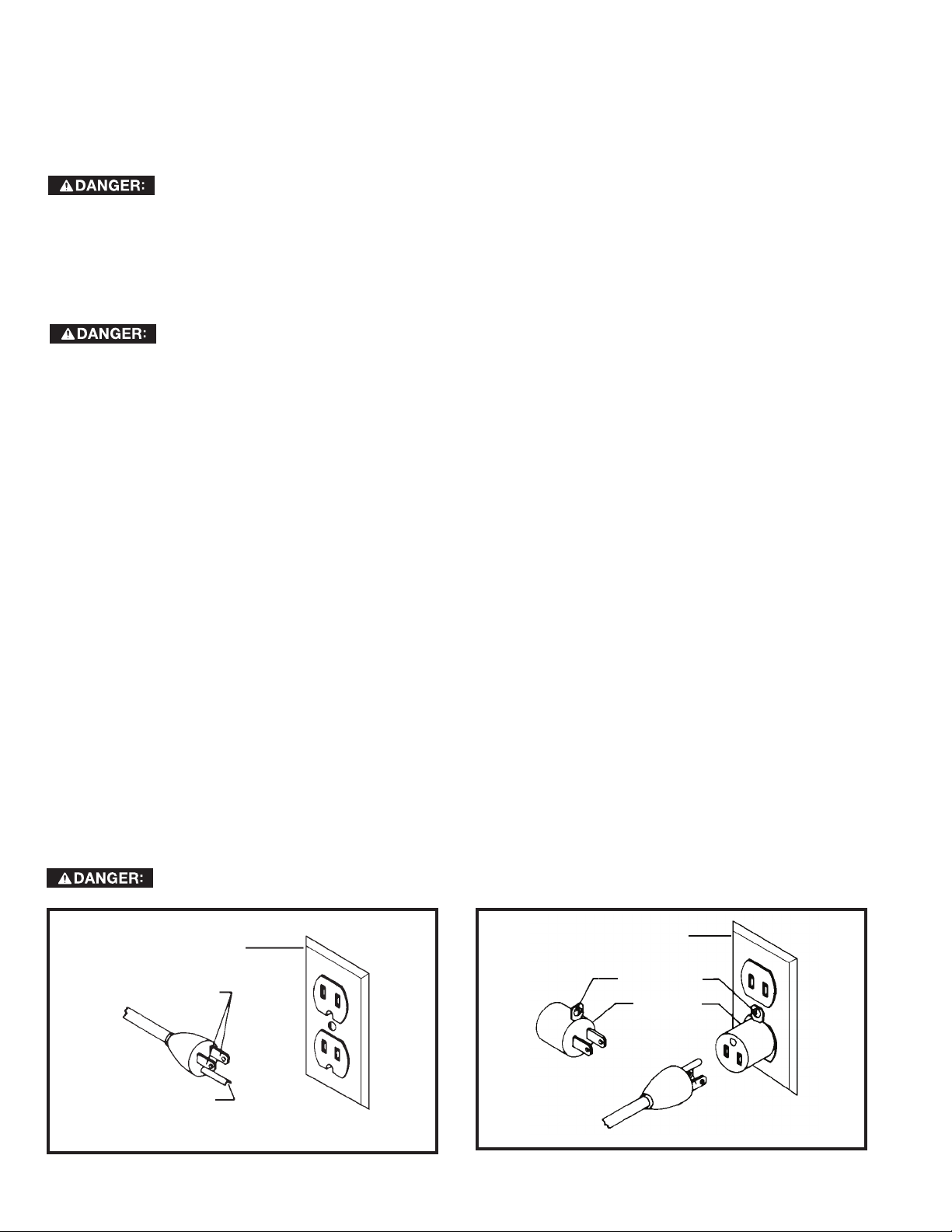
Use only 3-wire extension cords that have 3-prong grounding type plugs and matching 3-conductor receptacles that
accept the machine’s plug, as shown in Fig. A.
Repair or replace damaged or worn cord immediately.
2. Grounded, cord-connected machines intended for use on a supply circuit having a nominal rating less than
150 volts:
If the machine is intended for use on a circuit that has an outlet that looks like the one illustrated in Fig. A, the
machine will have a grounding plug that looks like the plug illustrated in Fig. A. A temporary adapter, which looks like
the adapter illustrated in Fig. B, may be used to connect this plug to a matching 2-conductor receptacle as shown
in Fig. B if a properly grounded outlet is not available. The temporary adapter should be used only until a properly
grounded outlet can be installed by a qualified electrician. The green-colored rigid ear, lug, and the like, extending
from the adapter must be connected to a permanent ground such as a properly grounded outlet box. Whenever the
adapter is used, it must be held in place with a metal screw.
NOTE: In Canada, the use of a temporary adapter is not permitted by the Canadian Electric Code.
IN ALL CASES, MAKE CERTAIN THE RECEPTACLE IN QUESTION IS PROPERLY GROUNDED.
IF YOU ARE NOT SURE, HAVE A QUALIFIED ELECTRICIAN CHECK THE RECEPTACLE.
GROUNDED
OUTLET BOX
CURRENT
CARRYING
PRONGS
GROUNDING BLADE
IS LONGEST OF THE 3 BLADES
FIG. A FIG. B
4
GROUNDED OUTLET BOX
GROUNDING
MEANS
ADAPTER
Page 5

EXTENSION CORDS
Use proper extension cords. Make
sure your extension cord is in good
condition and is a 3-wire extension cord which has a
3-prong grounding type plug and matching
receptacle which will accept the machine’s plug.
When using an extension cord, be sure to use one
heavy enough to carry the current of the machine.
An undersized cord will cause a drop in line voltage,
resulting in loss of power and overheating. Fig. C
shows the correct gauge to use depending on the
cord length. If in doubt, use the next heavier gauge.
The smaller the gauge number, the heavier the cord.
MINIMUM GAUGE EXTENSION CORD
RECOMMENDED SIZES FOR USE WITH STATIONARY ELECTRIC MACHINES
Ampere
Rating
0-6
0-6
0-6
0-6
6-10
6-10
6-10
6-10
10-12
10-12
10-12
10-12
12-16
12-16
12-16
Volts Total Length
120
120
120
120
120
120
120
120
120
120
120
120
120
120
120
of Cord in
Feet
up to 25
25-50
50-100
100-150
up to 25
25-50
50-100
100-150
up to 25
25-50
50-100
100-150
up to 25
25-50
GREATER THAN 50 FEET NOT RECOMMENDED
FIG. C
Gauge of Extension
Cord
18 AWG
16 AWG
16 AWG
14 AWG
18 AWG
16 AWG
14 AWG
12 AWG
16 AWG
16 AWG
14 AWG
12 AWG
14 AWG
12 AWG
FUNCTIONAL DESCRIPTION
FOREWORD
Model 50-871 3 Speed Digital Ambient Air Cleaner is specifically designed to quietly circulate and filter nonmetallic dust which is generated throughout the work area. The Air Cleaner is furnished with two filters: an outer
filter which filters particles that are five microns and larger, and a secondary disposable filter that captures 91%
of the dust particles that are one micron and larger (one micron = one millionth of a meter). Because breathing
microscopic particles can be a potential health hazard, filtering microscopic dust particles offers a cleaner and
safer environment. This Air Cleaner will filter the air in a room measuring 20’ x 20’ x 8’ either 13, 16, or 18 times an
hour, depending on the setting. If desired, multiple units can be used to filter larger areas. An occasional cleaning
and/or replacement of filters is the only required maintenance.
CARTON CONTENTS
1. Air cleaner
FIG. 1A
FIG. 1B
2. Remote Control Unit
(Batteries not included)
3. 1" Eye-Bolts (4)
4. Rubber Feet (4)
5. 5/16" Flange nuts (4)
5
Page 6

UNPACKING AND CLEANING
The Air Cleaner is shipped complete in one shipping container. Carefully unpack the Air Cleaner and all loose items
from the shipping container.
Styrofoam blocks have been packed inside the unit for protection. REMOVE THESE BLOCKS (A) Fig. 2 prior to use.
To Remove:
1. Disconnect unit from power source.
2. Remove outer filter by lifting up on the bottom and pulling out (Fig. 2A).
3. Remove inner filter by lifting up on the bottom and pulling out (Fig. 2B).
4. Remove styrofoam blocks (A) Fig. 2C and replace filters.
DO NOT LIFT THE AIR CLEANER BY POWER CORD.
FIG. 2A FIG. 2B FIG. 2C
INSTALLATION OPTIONS
Determine whether the Air Cleaner will be used on the floor, on a bench, or hanging from an overhead support.
If the Air Cleaner will be used as a mobile unit, proceed to “USING THE AIR CLEANER ON A BENCH OR FLOOR
SURFACE” section. If the unit will be ceiling-mounted, proceed to section “MOUNTING THE AIR CLEANER TO A
CEILING OR OVERHEAD SUPPORT.”
IMPORTANT: When determining where to mount the air cleaner, always select a location where the air flow is
unrestricted. Do not locate the unit in a corner or near any heating or cooling vents.
USING THE AIR CLEANER ON A BENCH OR FLOOR SURFACE
Locate (4) self-adhesive rubber feet (A) Fig. 3 supplied with the unit. Carefully place the Air Cleaner on a firm
supporting surface with access to the bottom of the cabinet. Apply a self-adhesive rubber foot (A) Fig. 3 to the
bottom at each corner of the air cleaner cabinet. The rubber feet will help eliminate vibration and will prevent the
possibility of the air cleaner “walking” across the floor or work surface.
For operator safety, clamp the unit to a work bench or position it securely on sawhorses.
The air cleaner cabinet has convenient lifting handles located on either side (one of which is shown at (A) Fig. 4). To
avoid damage to the air filters, carry the air cleaner with the filters positioned away from your body.
FIG. 3 FIG.4
6
Page 7
MOUNTING THE AIR CLEANER TO THE CEILING OR OVERHEAD SUPPORT
This unit weighs approximately 60 pounds. When mounting overhead, be certain that the unit is
securely fastened and supported.
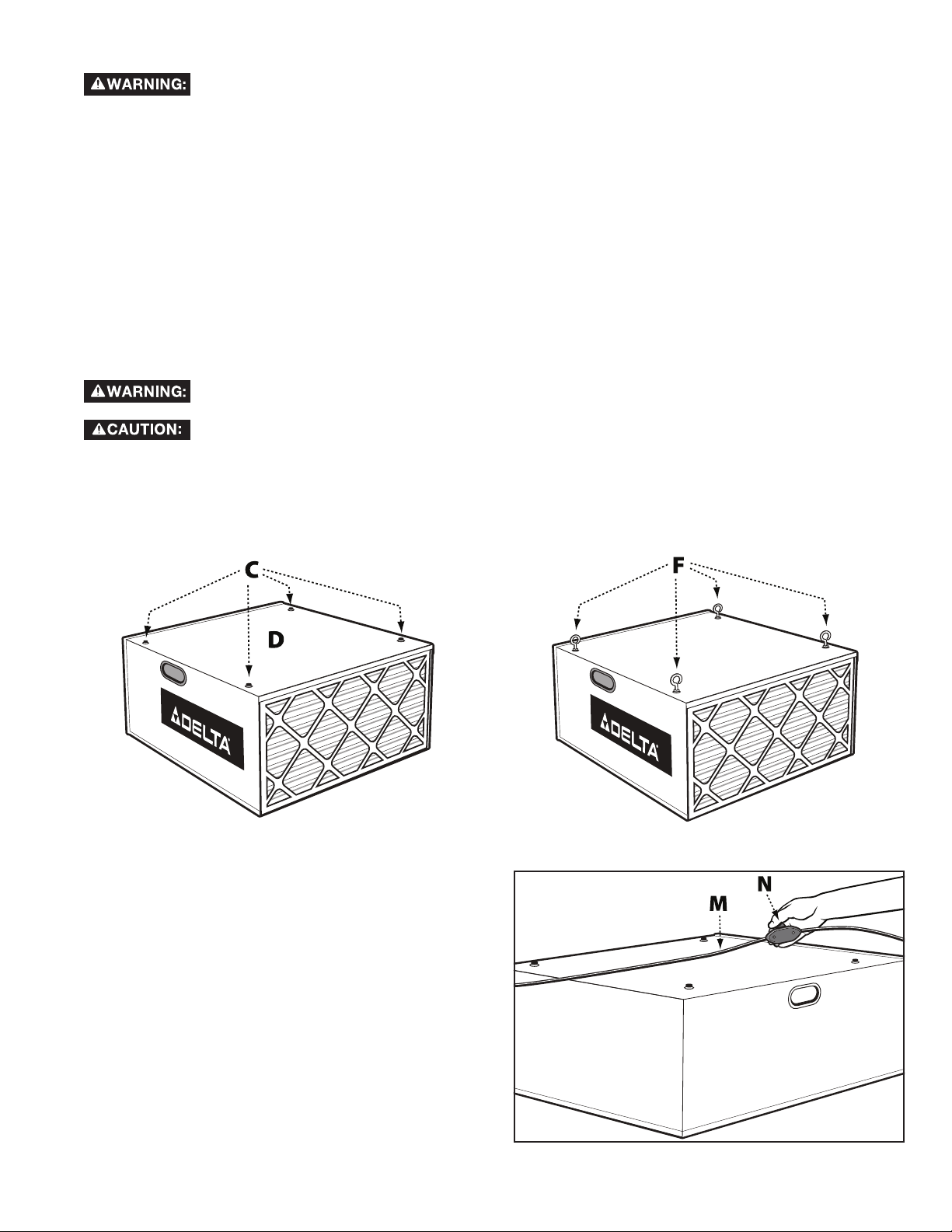
1. Locate the four 1" eye bolts and the four 5/16" Flange nuts supplied with the unit.
2. Use a flat blade screwdriver (not supplied) to remove the four screws (C) Fig. 5 from the top of air cleaner (D).
3. Thread one flange nut on each bolt approximately 5/16".
4. Thread the eye-bolts (F) Fig. 6 into the four holes where the screws were removed in STEP 2.
NOTE: Be certain that the flange nuts are tightened against the surface of the air cleaner.
NOTE: When suspending the air cleaner from the ceiling or other overhead support, use steel s-hooks that are a
minimum of 5/16".
NOTE: Thread all lag hooks at least 1-1/2" into the supporting structural members.
Never secure the air cleaner hardware to drywall, drop ceiling tile/frame, or other non-structural members.
Keep a minimum of seven feet between bottom of air cleaner and the floor surface.
Do not use rope, cable, or power cord to suspend the unit from the ceiling. Use chain rated
for a minimum of a 150 lb. working load.
IMPORTANT: When determining a location to mount the unit, the air cleaner will operate more efficiently when the air
flow is unrestricted. Do not locate the unit in a corner or near any heating or cooling vents.
FIG. 5 FIG. 6
ON/OFF SWITCH
The Air Cleaner is equipped with an in-line rocker
switch (M) Fig.7, located on the power cord (N). To
start or stop the motor, press downward on the rocker
switch, according to the markings on the side. When
you are finished with the air cleaner, turn the switch off
rather than unplug the unit.
NOTE: The ON-OFF Switch must be turned “ON”
before using the remote control feature.
FIG. 7
7
Page 8
USING THE REMOTE CONTROL
To reduce the risk of fire or electric
shock, do not use this unit with any
solid-state speed control device.
The remote control provided with this unit is not
considered a solid-state device.
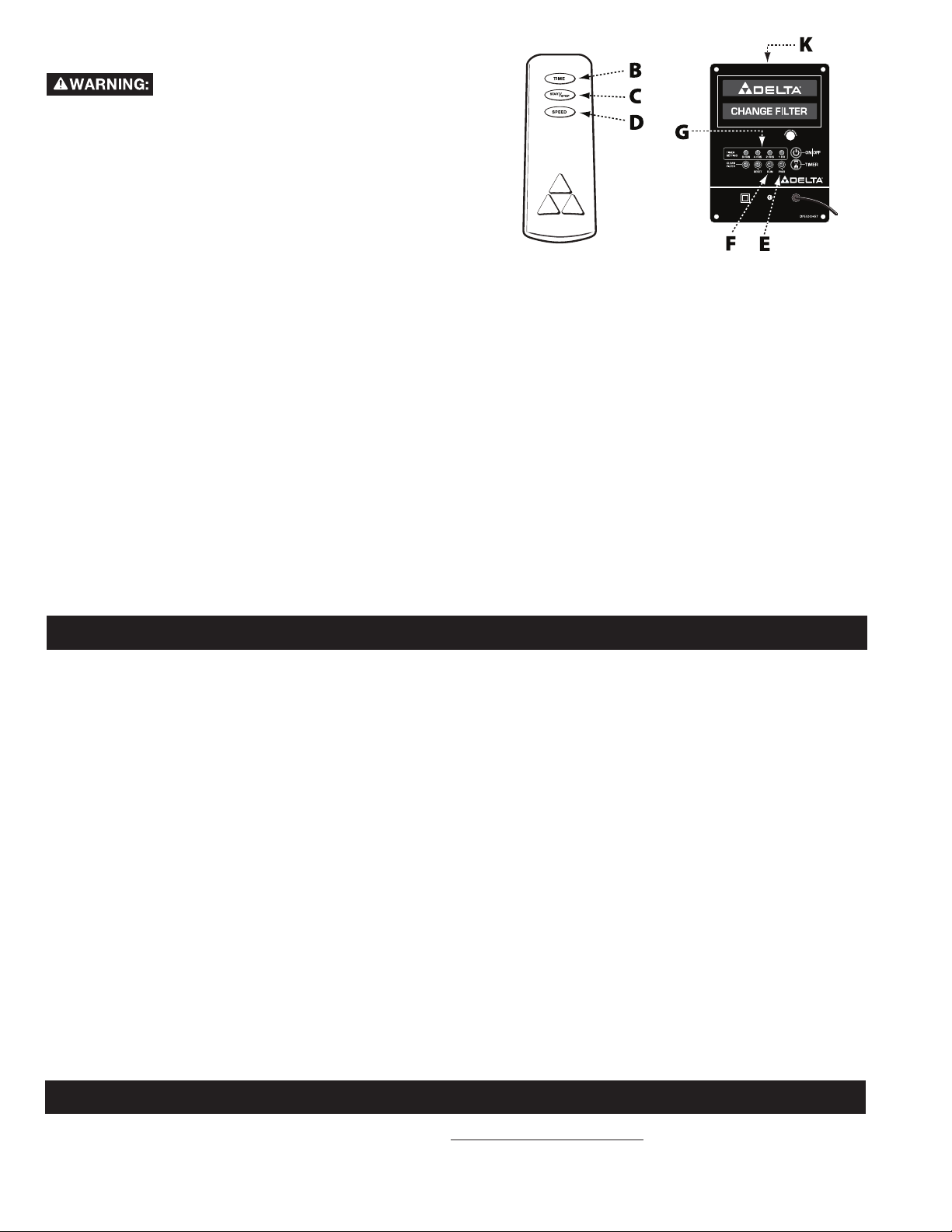
The Air Cleaner is equipped with a REMOTE CONTROL
(A) Fig.8A.
NOTE: The remote requires two (2) AAA batteries (not
supplied). The Battery housing is located underneath
the back cover.
Notice that the remote control has three control buttons
(Fig. 8A): TIME (B), ON/OFF (C), and SPEED (D). These
buttons correspond to the LED sensor panel on the
rear of the machine (K) Fig. 8B.
NOTE: When the machine is connected to the power
source, a green light (E) will be activated on the panel.
To activate the blower unit, press the "ON/OFF" button
(C) Fig. 8A. The machine will begin in the default speed
of HIGH on the sensor panel. Press the SPEED button
once, and the machine will run at the MEDIUM level.
Press the SPEED button again, and the machine will
run at the LOW level. Press the SPEED button a third
time, and the machine will return to HIGH speed mode.
To turn the machine off, press the “ON/OFF” button (C)
Fig. 8A.
This unit has a timer that can be set by remote control.
FIG. 8A FIG. 8B
When the machine is ON in the speed setting desired,
pressing the "TIME" button (B) Fig. 8A on the remote
control will set the machine to run for one hour.
Pressing the "TIME" button again will set the machine
to run for two hours. Notice that the light on the sensor
panel has now moved to the 2HR location (G) Fig. 8B.
When the "TIME" button is pressed a third time, the
machine will run for three hours. At this point the red
light will show up under the 1HR and 2HR locations.
When you press the "TIME" button a fourth time, the
unit will run for four hours. Notice that the indicator
light glows at the 4HR location. Pressing the "TIME"
button further will increase the time settings in one
hour increments to a maximum of fifteen hours.
All functions can be manually controlled by using the
two buttons on the sensor panel (K) Fig. 8B.
OPERATION
NOTE: The air cleaner may produce a slight odor for the first few hours of operation due to the protective coating
which is applied to internal components. This odor will dissipate and should be disregarded.
IMPORTANT: Never operate the air cleaner without air filters in place.
1. Make SURE that the filter material is correctly installed in place.
2. Plug in the power cord.
3. Press the ON/OFF button, START operation. (The RUN light will light up in the color of the relevant speed, and
the POWER light will stop flashing.)
4. Press the TIMER button to set the time, the MAX time setting is 15 hours.
The DELTA® 50-871 3 Speed Air Cleaner can be used in
a. bench-top sanding applications.
b. circular saw applications.
c. dry wall applications.
d. shop cleaning applications.
e. floor sanding applications.
f. any other application where non-metallic dust is a factor.
TROUBLESHOOTING
For assistance with your machine, visit our website at www.DeltaMachinery.com for a list of service centers or
call the DELTA® Power Equipment Corporation help line at 1-800-223-7278.
8
Page 9

MAINTENANCE
FILTER EXCHANGE
1. When CLEAN FILTER light illuminates, this means that the filter material needs to be changed.
2. After installing the new clean filter, make SURE to press CLEAN FILTER for 5 seconds, at which the POWER light
will begin to flash; PRESS the ON/OFF button to start operation.
3. Remove the outer first stage filter (A) Fig. 9A by lifting and pulling out on the bottom of the filter. Replace the
first stage filter depending on its condition. When you replace the outer filter, check to see if the filter has an
air flow arrow (A) Fig 9C. If so, point the arrow inward. If the filter does not have an air flow arrow, install the
filter either way.
When CLEAN FILTER light illuminates, this means that the filter material needs to be changed.
After installing the new clean filter, make SURE to press CLEAN FILTER for 5 seconds, at which the POWER light will
begin to flash; PRESS the ON/OFF button to start operation.
Compressed air can be dangerous. For operator safety, do not exceed an air pressure of 30 psi.
Do not point the air nozzle toward yourself or anyone else. Always wear safety glasses and a dust
mask when using compressed air.
4. Replace the filter, turn the unit "ON" and reset the digital indicator as below:
a) To reset the machine, press the RESET (Fig. 8B) button for about 5 seconds and wait for the CLEAN FILTER
signal to fade out. The PWR signal will start to flash; then press the ON/OFF button to run the machine.
RECOMMENDATIONS
If the pleated pre-filter has been changed 3 times, you MUST change the INNER filter once.
FIG. 9A
FIG. 9B
AIR FLOW
FIG. 9C
9
Page 10

ACCESSORIES
A complete line of accessories is available from your DELTA® Supplier, DELTA® Factory Service Centers, and DELTA®
Authorized Service Centers. Please visit our Web Site www.DeltaMachinery.com for an online catalog or for the
name or your nearest supplier.
Since accessories other than those offered by DELTA® have not been tested with this product,
use of such accessories could be hazardous. For safest operation, only DELTA® recommended
accessories should be used with this product.
PARTS, SERVICE OR WARRANTY ASSISTANCE
All DELTA® machines and accessories are manufactured to high quality standards and are serviced by a network of
DELTA® Factory Service Centers and DELTA® Authorized Service Centers. To obtain additional information regarding
your DELTA® quality product or to obtain parts, service, warranty assistance, or the location of the nearest service
center, please call 1-800-223-7278.
WARRANTY
To register your tool for warranty service visit our website at www.DeltaMachinery.com.
Five Year Limited New Product Warranty
DELTA® will repair or replace, at its expense and at its option, any new DELTA® machine, machine part, or machine accessory which in normal
use has proven to be defective in workmanship or material, provided that the customer returns the product prepaid to a DELTA
center or authorized service station with proof of purchase of the product within five years and provides DELTA
to verify the alleged defect by inspection. For all refurbished DELTA
for any asserted defect which has resulted from normal wear, misuse, abuse or repair or alteration made or specifically authorized by anyone
other than an authorized DELTA
damages resulting from defective products. Some states do not allow the exclusion or limitation of incidental or consequential damages, so the
above limitation or exclusion may not apply to you. This warranty is DELTA
with respect to defective products; all other warranties, express or implied, whether of merchantability, fitness for purpose, or otherwise, are
expressly disclaimed by DELTA
1-800-223-7278. This warranty gives you specific legal rights and you may have other rights which vary in certain states or provinces.
LATIN AMERICA: This warranty does not apply to products sold in Latin America. For products sold in Latin America,
see country specific warranty information contained in the packaging, call the local company or see website for warranty
information.
®
service facility or representative. Under no circumstances will DELTA® be liable for incidental or consequential
®
. For further detail of warranty coverage and warranty repair information, visit www.DeltaMachinery.com or call
®
product, the warranty period is 180 days. DELTA® will not be responsible
®
’s sole warranty and sets forth the customer’s exclusive remedy,
®
with reasonable opportunity
®
factory service
10
Page 11

REPLACEMENT PARTS
Use only identical replacement parts. For a parts list or to order parts, visit our website at www.DeltaMachinery.com/service. You
can also order parts from your nearest factory-owned branch, Authorized Warranty Service Center or by calling Technical
Service Manager at 1-800-223-7278 to receive personalized support from one of our highly-trained representatives.
FREE WARNING LABEL REPLACEMENT
If your warning labels become illegible or are missing, call
1-800-223-7278
for a free replacement.
FOR YOUR OWN SAFETY
1. READ AND UNDERSTAND
INSTRUCTION MANUAL
BEFORE OPERATING AIR
CLEANER.
2. To reduce the risk of injury,
disconnect from power supply
before servicing or changing
filters.
3. When ceiling mounted,
install Air Cleaner at least 7
feet above floor.
4. If used, ceiling mounts must
be anchored to building
structure. Never secure
mounts to dry wall, drop
ceiling tile/frame or other
non-structural members.
5. To reduce the risk of electrical
shock, do not expose to water
or rain.
6. Use only for the collection of
dry airborne dust. Never duct
the Air Cleaner directly to a
machine. Never use the Air
Cleaner to dissipate fumes
or smoke.
PARA SU PROPIA SEGURIDAD
1. LEA Y ENTIENDA EL MANUAL DE
INSTRUCCIONES ANTES DE
OPERAR EL LIMPIADOR DE AIRE.
2. Desconecte la unidad de la fuente
de energía antes de renidar
servicio o cambiar filtros para
reducir el riesgo de lesionamiento.
3. Instale el Limpiador de Aire por lo
menos 213 cm sobre el nievel del
piso cuando se trate de una
instalación de techno.
4. De utilizarse, los montajes de
techno deben anclarse a la
estructura del edificio. Jamás
afiance los mentajes al muro en
seco, lozas o marcos de platones
u otros miembros no estructurales.
5. No exponga la unidad al agua ni
la lluvia para reducir el riesgo de
choques eléctricos.
6. Utilice la unidad soló para la
recolección de polvo aéreo seco.
Jamás conduzca el Limpiador de
Aire directamente a una máquina.
Jamás utilice el Limplador de Aire
para disipar emanaciones o humo.
410-09-752-0017
To reduce risk of injury from moving parts, unplug before
servicing. Keep hands away from moving parts. Only
operate with air filters installed.
Desenchute la máquina antes de rendir servicio para
reducir el riesgo de lesionamientos ocasionados por
piezas en movimiento. Aleje las manos de las piezas
en movimiento. Opere solo con los filtros de aire
instalados.
410-09-752-0018
SERVICE AND REPAIRS
All quality tools will eventually require servicing and/or replacement of parts. For information
about DELTA® Power Equipment Corporation, its factory-owned branches, or to locate an
Authorized Warranty Service Center, visit our website at www.DeltaMachinery.com/service
or call our Customer Care Center at 1-800-223-7278. All repairs made by our service centers are fully
guaranteed against defective material and workmanship. We cannot guarantee repairs made or attempted by
others. By calling this number you can also find answers to most frequently asked questions 24 hours/day.
You can also write to us for information at DELTA® Power Equipment Corporation, 4825 Highway 45 North,
Jackson, TN 38305 - Attention: Technical Service Manager. Be sure to include all of the information shown
on the nameplate of your tool (model number, type, serial number, date code, etc.)
11
Page 12

IMPORTANTES CONSIGNES DE SÉCURITÉ
ASSUREZ-VOUS D’AVOIR BIEN LU ET COMPRIS TOUTES LES MISES EN
GARDE ET LES CONSIGNES D’UTILISATION AVANT D’UTILISER CET
ÉQUIPEMENT. Le fait de ne pas respecter toutes les instructions ci-dessous,
peut avoir pour conséquence : choc électrique, incendie et/ou blessures graves ou dégâts matériels.
Le travail du bois peut être dangereux si des procédures d’utilisation sécuritaires et adéquates ne sont pas
respectées. Comme c’est le cas pour toute pièce de machinerie, certains dangers sont assortis à l’utilisation de
ce produit. En utilisant cet appareil selon les directives et avec prudence, vous réduirez grandement la possibilité
de blessures. Cependant, si les précautions normales de sécurité sont négligées ou ignorées, la personne utilisant
l’appareil pourra être blessée. L’équipement de sécurité comme les dispositifs de protection, bâtons poussoir,
dispositif de retenue à ressort, cales-guide, lunettes, masques anti-poussière et protecteurs d’oreilles peut réduire
les risques de blessures. Mais même les dispositifs de protection les plus efficaces ne pourront vous protéger
contre un manque de jugement, de soin ou d’attention. Utilisez toujours votre bon sens et faites preuve de prudence
dans l’atelier. Si une manœuvre vous semble dangereuse, ne la tentez pas. Essayez plutôt de trouver une autre
solution qui vous paraît plus sûre. RAPPELEZ-VOUS : Vous êtes responsable de votre propre sécurité. Pour des
renseignements complémentaires, rendez-vous sur notre site web à l’adresse www.DeltaMachinery.com.
Cet appareil a été conçu seulement pour certains types d’utilisation. DELTA® Power
Equipment Corporation recommande fortement que cet appareil ne soit ni modifié ni utilisé à
toute autre fin que celles pour lesquelles il a été conçu. Si vous avez des questions sur un type d’utilisation en
particulier, N’UTILISEZ PAS l’appareil avant d’avoir d’abord contacté DELTA® pour déterminer si elle peut ou si elle
devrait être réalisée avec ce produit.
Si vous avez des questions sur son utilisation, N’UTILISEZ PAS le produit tant que vous n’avez pas écrit à
DELTA® Power Equipment Corporation et obtenu une réponse de leur part. Contactez-nous en ligne sur www.
DeltaMachinery.com ou par courrier à l’adresse suivante : responsable du service technique, DELTA® Power
Equipment Corporation, 4825 Highway 45 North, Jackson, TN 38305.
• Les informations concernant l’utilisation sûre et correcte de cet outil sont disponibles auprès des sources suivantes :
• Power Tool Institute, 1300 Sumner Avenue, Cleveland, OH 44115-2851 ou en ligne sur HYPERLINK http://www.
powertoolinstitute.com/ www.powertoolinstitute.com
• National Safety Council, 1121 Spring Lake Drive, Itasca, IL 60143-3201
• American National Standards Institute, 25 West 43rd Street, 4 floor, New York, NY 10036 HYPERLINK http://www.
ansi.org/ www.ansi.org - ANSI 01.1 Exigences de sécurité pour machines à bois
• U.S. Department of Labor regulations www.osha.gov
CONSIGNES DE SÉCURITÉ - DÉFINITIONS
Ce manuel contient des informations qu’il est important de connaître et de comprendre. Ces informations ont pour
but d’assurer VOTRE SÉCURITÉ et de PRÉVENIR LES PROBLÈMES D’ÉQUIPEMENT. Pour vous aider à reconnaître
ces informations, nous utilisons les symboles ci-dessous. Veuillez lire le manuel et prêter attention à ces sections-là.
indique une situation dangereuse imminente qui, si elle n’est pas évitée, provoquera la mort ou une
blessure grave.
indique une situation dangereuse potentielle qui, si elle n’est pas évitée, provoquera la mort
ou une blessure grave.
indique une situation dangereuse potentielle qui, si elle n’est pas évitée, peut provoquer une
blessure mineure ou modérée.
utilisé sans le symbole d’alerte de sécurité indique une situation potentiellement dangereuse qui,
si elle n’est pas évitée, peut entraîner des dommages matériels.
12
FRANÇAIS
Page 13

RÈGLES DE SÉCURITÉ GÉNÉRALES
LE NON-RESPECT DE CES RÈGLES PEUT PROVOQUER DES BLESSURES GRAVES.
POUR VOTRE PROPRE SÉCURITÉ, LISEZ ET COMPRENEZ LE MANUEL D’UTILISATION AVANT DE METTRE EN ROUTE
•
L’APPAREIL.
MAINTENIR L’AIRE DE TRAVAIL PROPRE.
•
NE PAS UTILISER DANS UN ENVIRONNEMENT DANGEREUX.
•
et ne l’exposez pas à la pluie.Gardez votre aire de travail bien éclairée.
ÉLOIGNER LES ENFANTS ET LES VISITEURS.
•
de travail.
DÉBRANCHER L’APPAREIL
•
VÉRIFIER LES PIÈCES ENDOMMAGÉES.
•
Apprenez l’utilisation de l’unité et ses limites ainsi que les risques spécifiques qui lui sont propres.
Les aires et bancs de travail encombrés attirent les accidents.
N’utilisez pas cet appareil dans un endroit humide ou mouillé,
Tous les enfants et visiteurs doivent demeurer à une distance sécuritaire de l’aire
avant toute opération d’entretien.
Avant d’utiliser l’appareil, bien réparer ou remplacer toute pièce endommagée.
LE NON-RESPECT DE CES RÈGLES PEUT PROVOQUER DES BLESSURES GRAVES.
NE PAS UTILISER CET APPAREIL POUR
FILTRER DE LA POUSSIÈRE DE MÉTAL.
Le fait de combiner de la poussière de bois et de métal peut
générer un danger d’explosion ou d’incendie. Cet appareil
est conçu pour filtrer uniquement des atmosphères non
explosives.
NE PAS UTILISER CET APPAREIL POUR
DISSIPER DES VAPEURS OU DES
FUMÉES. Des explosions ou incendies peuvent en
résulter. Ce système de filtration de l’air est conçu pour
une utilisation où seule une poussière sèche est présente
dans l’air. Son utilisation devrait être limitée aux
atmosphères non explosives et non métalliques.
1. NE PAS faire fonctionner cet appareil tant qu’il n’est
pas complètement monté et installé en respectant
les instructions. Un appareil qui n’est pas monté
correctement peut provoquer des blessures.
2. DEMANDEZ CONSEIL à votre supérieur, instructeur
ou à une autre personne qualifiée, si vous n’êtes pas
familier avec le fonctionnement de cet appareil. Vos
connaissances sont garantes de votre sécurité.
3. RESPECTER TOUS LES CODES DE CÂBLAGE et
connexions électriques recommandés pour éviter un
choc électrique ou une électrocution.
4. NE PAS SOULEVER CET APPAREIL PAR LE
CORDON D’ALIMENTATION. Ne pas utiliser le cordon
d’alimentation comme un dispositif d’accrochage. Un
cordon d’alimentation endommagé peut provoquer un
choc électrique ou une électrocution.
5. BIEN FIXER CET APPAREIL à une structure de
support permanente ou fixe quand il est suspendu
au plafond. La chute d’un appareil peut provoquer
de graves blessures. Toujours garder un minimum de
2,15 m (7 pieds) entre le fond de l’appareil et la surface
du plancher pour garantir une distance suffisante
au-dessus de la tête. Utilisez uniquement une chaîne
capable de soutenir une charge de travail minimum de
68,2 kg (150 livres) de façon à bien maintenir l’appareil.
Utilisez des crochets d’acier en S d’un diamètre d’au
moins 6,4 mm (1/4 po) pour suspendre l’appareil au
plafond. Les tire-fonds utilisés pour suspendre
l’appareil au plafond doivent être filetés sur au moins
38 mm (1 1/2 po) dans la charpente.
6. SOUTENIR cet appareil ou le fixer solidement
à la surface de travail quand il est utilisé de façon
portable pour éviter les blessures potentielles et/ou
d’endommager l’appareil.
7. S’ASSURER QUE LES ZONES D’ENTRÉE ET
DE SORTIE SONT DÉGAGÉES avant de démarrer
l’appareil. Des zones d’entrée ou de sortie bouchées
peuvent provoquer une explosion et/ou un incendie.
8. GARDER SES BRAS, MAINS et doigts LOIN DES
PALES DU VENTILATEUR. Évitez tout contact avec les
pièces rotatives pour prévenir les blessures.
9. NE PAS UTILISER CET APPAREIL SANS LES
FILTRES EN PLACE. La poussière et autres petits
débris iront directement au moteur, ce qui provoquera
une surchauffe et un incendie et/ou une explosion
potentiels.
10. NE PAS TENTER d’enlever ou de remplacer le ou
les filtres lorsque l’appareil est en marche. Les pales
apparentes du ventilateur peuvent provoquer de graves
coupures. Assurez-vous que l’appareil est débranché
de la source d’alimentation.
11. MAINTENIR L’APPAREIL en excellent état. Des filtres
bouchés peuvent augmenter le risque d’incendie ou
d’explosion. Suivez les consignes pour changer et
nettoyer les filtres.
12. GARDER L’APPAREIL dans un endroit où le cordon
d’alimentation ne peut pas être endommagé. Un
cordon d’alimentation abîmé peut provoquer un choc
électrique ou une électrocution. Bien ranger le cordon
d’alimentation sur l’appareil pour éviter que quelqu’un
ne trébuche dessus.
13. ÉTEINDRE L’APPAREIL et le débrancher de la
source d’alimentation avant d’installer ou d’enlever
des accessoires, avant d’ajuster ou de modifier des
réglages ou avant de faire des réparations. Une mise en
route accidentelle peut provoquer de graves blessures.
14. DÉBRANCHEZ l’appareil de la source d’alimentation
avant de procéder à l’entretien ou au changement du
filtre, de déboucher ou de nettoyer l’unité.
15. REMPLACEZ ou réparez immédiatement tout cordon
d’alimentation endommagé ou usé.
16. NE faites PAS fonctionner un ventilateur dont
le cordon ou la fiche est endommagé. Éliminez le
ventilateur ou retournez-le auprès d’un centre de
réparation autorisé afin qu’il soit examiné et/ou réparé.
17. NE faites PAS passer le cordon sous un tapis ou une
moquette. NE couvrez PAS le cordon avec une moquette,
un tapis de passage ou autre. Disposez le cordon en dehors
des zones de passage, là où il ne fera pas trébucher.
CONSERVER CES CONSIGNES.
Consultez-les souvent et utilisez-les pour enseigner aux autres.
13
Page 14

BRANCHEMENTS
Un circuit électrique séparé doit être utilisé pour vos appareils. Ce circuit ne doit pas comporter de fils de calibre de moins de 12 et
doit être protégé par un fusible à action différée de 20 ampères. Si vous utilisez une rallonge, ne prenez que des rallonges à 3 fils avec
fiche de mise à la terre à 3 branches et un réceptacle correspondant qui acceptera la prise de l’appareil. Avant de brancher l’appareil
sur l’alimentation, assurez-vous que l’interrupteur est en position « OFF » et que le courant électrique que vous allez utiliser possède
les mêmes caractéristiques que celui indiqué sur l’appareil. Toutes les connexions électriques doivent établir un bon contact. Une
utilisation en basse tension endommagera l’appareil.
NE PAS UTILISER L’APPAREIL DANS UN ENDROIT HUMIDE OU MOUILLÉ, ET NE PAS L’EXPOSER
À LA PLUIE.
SPÉCIFICATIONS DU MOTEUR
Votre appareil est câblé pour un courant alternatif de 120 V, 60 Hz. Avant de brancher l’appareil sur la source d’alimentation, assurezvous que l’interrupteur est en position « OFF ».
DIRECTIVES DE MISE À LA TERRE
CET APPAREIL DOIT ÊTRE MIS À LA TERRE LORSQU’IL EST EN MARCHE POUR PROTÉGER
CELUI QUI LE MANIPULE D’UN CHOC ÉLECTRIQUE.
1. Pour tous les appareils branchés par un cordon d’alimentation et mis à la terre :
Dans le cas d’un dysfonctionnement ou d’une panne, la mise à la terre fournit un chemin de moindre résistance au courant électrique
pour réduire le risque de choc électrique. Cet appareil est équipé d’un cordon électrique possédant un conducteur de terre et une
fiche de terre. La fiche doit être branchée sur une prise correctement installée et mise à la terre conformément à tous les codes et
règlements locaux.
Ne pas modifier la fiche fournie - si elle n’entre pas dans la prise, faites installer une prise adéquate par un électricien qualifié. Un
branchement incorrect du conducteur de terre peut entraîner un risque de choc électrique. Le conducteur avec
un isolant comportant une surface extérieure verte, avec ou sans rayures jaunes, est le conducteur de terre.
Si la réparation ou le remplacement du cordon électrique ou de la fiche est nécessaire, ne pas brancher le conducteur de terre à une
borne sous tension.
Si les instructions de mise à la terre ne sont pas complètement comprises, ou si vous doutez que l’appareil soit correctement relié à la
terre, vérifiez avec un électricien qualifié ou le personnel de service.
Utilisez uniquement des rallonges à 3 fils avec fiche de mise à la terre à 3 branches et des réceptacles adaptés acceptant la prise de
l’appareil, tels que sur la Fig. A.
Réparez ou remplacez immédiatement un cordon abîmé ou usé.
2. Appareils reliés à la terre et branchés par l’intermédiaire d’un cordon d’alimentation destinés à une utilisation
sur un circuit d’alimentation ayant une puissance nominale de moins de 150 volts :
Si l’appareil est destiné à être utilisé sur un circuit possédant une sortie qui ressemble à celle dessinée sur la Fig. A, l’appareil aura
une prise de terre ressemblant à celle dessinée sur la Fig. A. Un adaptateur temporaire ressemblant à celui dessiné sur la Fig. B, peut
être utilisé pour connecter cette fiche à un réceptacle à 2 conducteurs comme dans la Fig. B si une prise de terre appropriée n’est pas
disponible. L’adaptateur temporaire doit être utilisé uniquement jusqu’à ce qu’une prise de terre appropriée puisse être installée par
un électricien qualifié. La cosse rigide de couleur verte, la patte, l’ergot, etc. sortant de l’adaptateur doivent être branchés à la terre
de façon permanente par l’intermédiaire d’une boîte de prise de terre. Chaque fois que l’adaptateur est utilisé, il doit être maintenu en
place avec une vis en métal.
REMARQUE : Au Canada, l’utilisation d’un adaptateur temporaire n’est pas autorisée par le Code canadien de l’électricité.
DANS TOUS LES CAS, ASSUREZ-VOUS QUE LE RÉCEPTACLE EN QUESTION EST BIEN RELIÉ
À LA TERRE. SI VOUS N’ÊTES PAS SÛR, FAITES VÉRIFIER LE RÉCEPTACLE PAR UN
ÉLECTRICIEN QUALIFIÉ.
PRISE DE
TERRE
FICHES
CONDUCTRICES DE
COURANT
FICHE DE MISE À
LA TERRE EST LA PLUS LONGUE DES 3 FICHES
FIG. A FIG. B
14
BOÎTE DE PRISE DE TERRE
BORNIERS
MOYENS
ADAPTATEUR
Page 15

RALLONGES
Utilisez des rallonges
adéquates. Assurez-vous
que votre rallonge est en bon état et que
c’est bien une rallonge 3 fils avec une fiche
de mise à la terre à 3 branches et un
réceptacle correspondant qui acceptera la
prise de l’appareil. Lorsque vous utilisez une
rallonge, assurez-vous qu’elle soit capable de
supporter le courant de l’appareil. Un cordon
de trop faible capacité provoquera une chute
de tension sur la ligne, entraînant une perte
de puissance et de la surchauffe. La Fig. C
montre la jauge appropriée du cordon de
prolongation à utiliser en fonction de sa
longueur. Si vous avez un doute, utilisez le
cordon de prolongation de jauge
immédiatement supérieur. Plus le numéro est
petit, plus la jauge est grosse.
AUGE MINIMUM POUR CORDON PROLONGATEUR
CALIBRES RECOMMANDÉS POUR UNE UTILISATION AVEC DES APPAREILS ÉLECTRIQUES STATIONNAIRES
Ampérage
Service
Nominal
0 À 6
0 À 6
0 À 6
0 À 6
6 À 10
6 À 10
6 À 10
6 À 10
10 À 12
10 À 12
10 À 12
10 À 12
12 À 16
12 À 16
12 À 16
Volts
120
120
120
120
120
120
120
120
120
120
120
120
120
120
120
Longueur Totale Du Cordon
25 À 50 (7,62 À 15,24 M)
50 À 100 (15,24 À 30,48 M)
100 À 150 (30,48 À 45,72 M)
25 À 50 (7,62 À 15,24 M)
50 À 100 (15,24 À 30,48 M)
100 À 150 (30,48 À 45,72 M)
25 À 50 (7,62 À 15,24 M)
50 À 100 (15,24 À 30,48 M)
100 À 150 (30,48 À 45,72 M)
25 À 50 (7,62 À 15,24 M)
En Pieds
JUSQU’À 25 (7,62 M)
JUSQU’À 25 (7,62 M)
JUSQU’À 25 (7,62 M)
JUSQU’À 25 (7,62 M)
LES RALLONGES DE PLUS DE 50 PIEDS (15,24 M) NE SONT PAS
FIG. C
RECOMMANDÉES
Jauge Des Fils
Électriques De La
Rallonge
18 AWG
16 AWG
16 AWG
14 AWG
18 AWG
16 AWG
14 AWG
12 AWG
16 AWG
16 AWG
14 AWG
12 AWG
14 AWG
12 AWG
DESCRIPTION DU FONCTIONNEMENT
AVANT-PROPOS
Le système de filtration de l’air DELTA® modèle 50-871 est spécifiquement conçu pour faire circuler et filtrer
silencieusement la poussière non métallique générée au sein de l’aire de travail. Le système de filtration de l’air
est fourni avec deux filtres : un filtre externe filtrant les particules de cinq microns et plus, et un filtre secondaire
jetable qui capte 91 % des particules de poussière d’un micron et plus (un micron = un millionième de mètre).
Étant donné qu’inhaler des particules microscopiques peut être un danger pour la santé, la filtration des particules
microscopiques de poussière offre un environnement plus propre et plus sûr. Ce système de filtration de l’air sera
en mesure de filtrer l’air d’une pièce mesurant 6 x 6 x 2,45 m (20 pi x 20 pi x 8 pi), 13, 16 ou 18 fois par heure, selon
le réglage. Si vous le souhaitez, plusieurs appareils peuvent être utilisés pour filtrer des zones plus vastes. Un
nettoyage et/ou le remplacement occasionnel des filtres est le seul entretien nécessaire.
CONTENU DU CARTON
FIG. 1A
1. Système de filtration de l’air
FIG. 1B
2. Télécommande
(Piles non comprises)
3. Boulons à œil (4) de 2,54 cm (1 po)
4. Supports en caoutchouc (4)
5. Écrous à bride de 5/16-20 (4)
15
Page 16

DÉBALLAGE ET NETTOYAGE
Le système de filtration de l’air est expédié complet dans une caisse d’expédition. Déballez minutieusement le
système de filtration de l’air et toutes les pièces détachées se trouvant dans la caisse d’expédition.
Des blocs de styromousse ont été emballés avec l’appareil pour le protéger. ENLEVER CES BLOCS (A) Fig. 2 avant
l’utilisation. Pour enlever :
1. Débrancher l’appareil de la source d’alimentation.
2. Retirer le filtre externe en soulevant le bas et en tirant vers l’extérieur (Fig. 2A).
3. Retirer le filtre interne en soulevant le bas et en tirant vers l’extérieur (Fig. 2B).
4. Retirer les blocs de styromousse (A) Fig. 2C et remplacer les filtres.
NE PAS SOULEVER LE SYSTÈME DE FILTRATION DE L’AIR PAR LE CORDON D’ALIMENTATION.
FIG. 2A FIG. 2B FIG. 2C
MONTAGE
Déterminez si le système de filtration de l’air sera utilisé sur le plancher, sur un établi ou s’il sera suspendu d’un support
en hauteur. Si le système de filtration de l’air est utilisé en tant qu’appareil mobile, allez à la section « UTILISER LE
SYSTÈME DE FILTRATION DE L’AIR SUR UN ÉTABLI OU SUR LE PLANCHER ». Si l’appareil est fixé au plafond, allez à
la section « FIXER LE SYSTÈME DE FILTRATION DE L’AIR AU PLAFOND OU À UN SUPPORT EN HAUTEUR. »
IMPORTANT : Au moment de décider de l’emplacement du système de filtration de l’air, toujours choisir un endroit où l’air
circule librement. Ne pas placer l’appareil dans un coin ou près de bouches de chauffage ou de refroidissement.
UTILISER LE SYSTÈME DE FILTRATION DE L’AIR SUR UN ÉTABLI OU
SUR LA SURFACE DU PLANCHER
Localiser (4) pieds en caoutchouc auto-adhésif (A) Fig. 3 fournis avec l’appareil. Placer avec précaution le système
de filtration de l’air sur une surface ferme où vous pourrez avoir accès à la partie inférieure de l’appareil. Placer
un pied en caoutchouc auto-adhésif (A) Fig. 3 sur la partie inférieure de l’appareil, à chaque coin. Les pieds en
caoutchouc aideront à supprimer la vibration et éviteront que le système de filtration de l’air se déplace à travers la
pièce ou l’aire de travail.
Pour la sécurité de celui qui le manipule, fixez l’appareil à un établi ou positionnez-le solidement sur des chevalets.
Le coffre du système de filtration de l’air est pourvu de poignées pratiques de chaque côté pour le soulèvement (une
d’entre elles est visible sur (A) la Fig. 4). Pour éviter d’endommager les filtres à air, assurez-vous que ces derniers ne
sont pas en contact avec votre corps lorsque vous transportez l’appareil.
FIG. 3 FIG.4
16
Page 17

FIXER LE SYSTÈME DE FILTRATION DE L’AIR AU PLAFOND OU À UN
SUPPORT EN HAUTEUR
Cet appareil pèse environ 27,22 kg (60 livres). Lorsque vous le fixez en hauteur, assurezvous que l’appareil est bien attaché et soutenu.
1. Prenez les 4 boulons à œil de 2,54 cm (1 po) et les 4 écrous à bride de 5/16 fournis avec l’appareil.
2. Utilisez un tournevis plat (non fourni) pour enlever les 4 vis (C) Fig. 5 sur le dessus du système de filtration de l’air (D).
3. Vissez un écrou à bride sur chaque boulon d’environ 19,1 mm (5/16" po).
4. Placez les boulons à œil (F) Fig. 6 dans les 4 trous d’où les vis ont été retirées à l’ÉTAPE 2.
REMARQUE : Assurez-vous que les écrous à bride sont bien serrés à la surface du système de filtration de l’air.
REMARQUE : Pour fixer l’appareil au plafond ou sur un support en hauteur, utilisez des crochets d’acier en S d’un
diamètre d’au moins 6,4 mm (5/16 po).
REMARQUE : Placez tous les tire-fonds à au moins 38 mm (1 1/2 po) dans la charpente.
Ne jamais fixer le système de filtration de l’air sur de la cloison sèche, sur des carreaux
de faux-plafond ou d’autres éléments qui ne font pas partie de la charpente.
Garder un minimum de 2,14 m (7 pieds) entre la partie inférieure du système de filtration de l’air
et la surface du plancher.
Ne pas utiliser une corde, un câble, ou un cordon d’alimentation pour suspendre l’appareil au plafond.
Utilisez une chaîne adaptée à une charge de travail de 68 kg minimum (150 livres).
IMPORTANT : Au moment de décider de l’emplacement du système de filtration de l’air, pensez que l’appareil
fonctionnera plus efficacement dans un endroit où l’air circule librement. Ne pas placer l’appareil dans un coin ou
près de bouches de chauffage ou de refroidissement.
FIG. 5 FIG. 6
INTERRUPTEUR MARCHE/
ARRÊT (ON/OFF)
Le système de filtration de l’air est équipé d’un
interrupteur à bascule en ligne (M) Fig.7, situé sur le
cordon d’alimentation (N). Pour mettre en route ou
arrêter le moteur, appuyez vers le bas sur l’interrupteur
à bascule, en suivant les instructions sur le côté.
Lorsque vous avez fini d’utiliser le système de filtration
de l’air, éteignez-le en appuyant sur l’interrupteur plutôt
que de le débrancher.
REMARQUE : L’interrupteur MARCHE/ARRÊT
(ON-OFF) doit être mis sur « ON » avant d’utiliser la
télécommande.
17
FIG. 7
Page 18

UTILISER LA TÉLÉCOMMANDE
Pour réduire le risque
d’incendie ou de choc
électrique, ne pas utiliser cet appareil avec tout
dispositif de contrôle de vitesse à semi-conducteur.
La télécommande fournie avec cet appareil n’est
pas considérée comme un dispositif de contrôle de
vitesse à semi-conducteur.
Le système de filtration de l’air est équipé d’une
TÉLÉCOMMANDE (A) Fig.8A.
REMARQUE : La télécommande nécessite deux (2)
piles AAA (non fournies). Le compartiment à piles est
situé sous le couvercle arrière.
Notez que la télécommande possède trois boutons de
commande
REMARQUE : Quand l’appareil est branché à la
source d’alimentation, un voyant vert (E) s’allume sur
le panneau.
Pour activer le ventilateur, enfoncez le bouton « ON/
OFF » (MARCHE/ARRÊT) (C) Fig. 8A. L’appareil
démarrera à la vitesse ÉLEVÉE par défaut sur le
panneau des capteurs. Enfoncez une fois le bouton
« SPEED » (VITESSE), l’appareil fonctionnera à une
vitesse MOYENNE. Enfoncez le bouton « SPEED » à
nouveau, l’appareil fonctionnera à FAIBLE vitesse.
Enfoncez le bouton « SPEED » une troisième fois,
l’appareil reviendra au mode de vitesse ÉLEVÉE.
Pour éteindre l’appareil, appuyez sur le bouton
MARCHE/ARRÊT (ON/OFF) (C) Fig. 8A.
Lorsque l’appareil est en MARCHE au réglage de
vitesse désiré, l’enfoncement du bouton « TIME »
(HEURE) (B) Fig. 8A de la télécommande réglera
FIG. 8A
l’appareil pour un fonctionnement d’une durée d’une
heure. Appuyer une deuxième fois sur le bouton
« TIME » permettra à l’appareil de fonctionner
pendant deux heures. Veuillez prendre note que le
voyant apparaissant sur le panneau de capteurs
est maintenant à l’emplacement « 2HR » (G) Fig.
8B. Lorsque vous appuyez une troisième fois sur le
bouton « TIME », l’appareil fonctionnera pendant trois
heures. À ce moment, le voyant rouge s’allumera
sous l’emplacement « 1HR » et « 2HR ». Lorsque vous
appuyez sur « TIME » pour la quatrième fois, l’appareil
fonctionnera pendant quatre heures. Veuillez prendre
note que le voyant luit à l’emplacement de « 4HR ».
En appuyant de nouveau sur le bouton « TIME », la
durée des réglages augmentera par tranches d’une
heure pour un maximum de quinze heures. .
Toutes ces fonctions peuvent être contrôlées
manuellement en utilisant les deux boutons du
panneau capteur (K) Fig. 8B.
FIG. 8B
OPÉRATIONS
REMARQUE : Le nettoyeur à air peut produire une légère odeur pendant les premières heures d’utilisation en raison
du revêtement protecteur appliqué sur les composants internes. Cette odeur se dissipera et ne devrait pas être prise
en compte.
IMPORTANT : Ne jamais utiliser le nettoyeur à air si les filtres à air ne sont pas en place.
1. S’ASSURER que le matériel du filtre est bien installé.
2. Brancher le cordon d’alimentation; mettre en fonction l’interrupteur du cordon en ligne à ON (MARCHE). (Le
voyant POWER (d’ALIMENTATION) clignotera de manière constante).
3. Appuyer sur la touche ON/OFF (MARCHE/ARRÊT), DÉBUTER l’utilisation. (Le voyant RUN (EN MARCHE)
s’allumera selon la couleur de la vitesse pertinente, et le voyant POWER (ALIMENTATION) cessera de clignoter).
4. Appuyer sur la touche TIMER (MINUTERIE), le réglage MAX de l’heure est de 15 heures.
Le système de nettoyage de l’air DELTA® 50-871 3 vitesses peut être utilisé pour :
a. applications de ponçage sur table.
b. applications sur scie circulaire.
c. applications sur cloisons sèches.
d. applications de nettoyage d’usine.
e. applications pour sabler le plancher.
f. toute autre application où la poussière non métallique est un facteur.
DIAGNOSTIC DES ANOMALIES
Pour une assistance sur votre appareil, rendez-vous sur notre site à l’adresse www.DeltaMachinery.com pour
obtenir la liste des centres de service ou appelez l’assistance de DELTA® Power Equipment Corporation au
1 800 223-7278.
18
Page 19

ENTRETIEN
CHANGER ET NETTOYER LES FILTRES
1. Lorsque le voyant CLEAN FILTER (NETTOYER FILTRE) s’allume, cela signifie que le matériel du filtre doit être
changé.
2. Après l’installation du nouveau filtre propre, S’ASSURER d’appuyer sur la touche CLEAN FILTER (NETTOYER
FILTRE) pendant 5 secondes. À ce moment, le voyant POWER (ALIMENTATION) commencera à clignoter;
APPUYER sur la touche ON/OFF (MARCHE/ARRÊT) pour débuter l’opération.
3. Retirer le filtre primaire extérieur (D) Fig. 9B en soulevant et tirant la partie inférieure du filtre. Replacer le filtre
primaire selon sa condition. Lors du remplacement du filtre extérieur, vérifier si le filtre est muni d’une flèche de
circulation d’air (A) Fig. 9D. Si tel est le cas, pointer la flèche vers l’intérieur. Si le filtre n’est pas muni d’une flèche
de circulation d’air, installer le filtre d’une façon ou d’une autre.
Lorsque le voyant CLEAN FILTER (NETTOYER FILTRE) s’allume, cela signifie que le matériel du filtre doit être
changé.
Après l’installation du nouveau filtre propre, S’ASSURER d’appuyer sur la touche CLEAN FILTER (NETTOYER
FILTRE) pendant 5 secondes. À ce moment, le voyant POWER (ALIMENTATION) commencera à clignoter; APPUYER
sur la touche ON/OFF (MARCHE/ARRÊT) pour débuter l’opération.
L’air comprimé peut s’avérer dangereux. Pour la sécurité de l’opérateur, ne pas dépasser
une pression d’air de 8,97 kg/cm2 (30 psi). Ne pas pointer la buse à air vers vous ou une
autre personne. Toujours porter des lunettes de sécurité et un masque antipoussière au moment d’utiliser de l’air
comprimé.
4. Remplacez le filtre, mettez l’appareil en marche (« ON ») et réinitialiser l’indicateur numérique comme ci-dessous :
a) Pour réinitialiser l’appareil, appuyez sur le bouton « RESET » (RÉINITIALISER) (Fig. 8B) pendant environ 5
secondes et attendez que le signal « CLEAN FILTER » (NETTOYER LE FILTRE) s’estompe. Le signal « PWR »
(ALIMENTATION) commencera à clignoter; appuyez ensuite sur le bouton « ON/OFF » (MARCHE/ARRÊT) pour
mettre l’appareil en marche.
RECOMMENDATIONS
Si le préfiltre plissé a été changé trois fois, vous DEVEZ changer le filtre interieur une fois.
FIG. 9A
FIG. 9B
FIG. 9C
19
AIR FLOW
Page 20

ACCESSOIRES
La gamme complète des accessoires peut être obtenue auprès de votre fournisseur DELTA®, des centres de
service du fabricant et des centres de service DELTA® autorisés. Rendez-vous sur notre site à l’adresse www.
DeltaMachinery.com pour obtenir un catalogue, ou pour connaître le nom de votre fournisseur le plus proche.
Étant donné que les accessoires autres que ceux offerts par DELTA® n’ont pas été testés
avec ce produit, leur utilisation pourrait être dangereuse. Pour une utilisation en toute
sécurité, seuls les accessoires recommandés par DE LTA® doivent être utilisés avec ce produit.
ASSISTANCE PIÈCES, SERVICE ET GARANTIE
Tous les appareils et tous les accessoires DELTA® sont fabriqués selon des normes de qualité exigeantes et sont
soutenus par un réseau de centres de service du fabricant et de centres de service DE LTA® autorisés. Pour en
savoir plus sur votre produit de qualité DE LTA®, obtenir des pièces, du service, une assistance quant à la garantie ou
l’emplacement du centre de service le plus proche de chez vous, veuillez composer le 1 800 223-7278.
GARANTIE
Pour l’enregistrement de votre appareil auprès du service de la garantie, rendez-vous sur notre site à l’adresse
www.DeltaMachinery.com.
Garantie limitée de cinq ans pour les produits neufs
DELTA® réparera ou remplacera, à ses frais et à sa discrétion, tout nouvel appareil, pièce ou accessoire de l’appareil de DELTA® qui, pour une
usure normale, est jugé défectueux en raison d’un défaut de fabrication ou de matériau, à condition que le client retourne le produit prépayé
à un centre de service du fabricant ou à un centre de service autorisé DELTA
l’achat et offre à DELTA
reconditionnés, la durée de garantie est de 180 jours. DELTA
d’une mauvaise utilisation, d’abus ou de réparations ou d’altérations faites ou expressément autorisées par quiconque autre qu’un centre
de service ou un représentant de DELTA
indirects résultant de produits défectueux. Certains États ne permettant pas l’exclusion ou la limitation des dommages directs ou indirects, la
limitation ou exclusion peut ne pas s’appliquer à votre cas. Cette garantie est la seule garantie de DELTA
client en ce qui concerne les produits défectueux; toute autre garantie, expresse ou implicite, que ce soit de la valeur marchande, de la capacité
de remplir une fonction ou autre, est expressément exclue par DELTA
informations sur les réparations sous garantie, rendez-vous sur notre site à l’adresse www.DeltaMachinery.com ou appelez le 1 800 223-7278.
Cette garantie vous donne des droits légaux spécifiques et vous pouvez avoir d’autres droits qui sont différents selon les États ou provinces.
AMÉRIQUE LATINE : Cette garantie ne s’applique pas aux produits vendus en Amérique latine. Pour les produits vendus
en Amérique latine, voir les informations de garantie relatives au pays en question contenues dans le carton, appeler la
société locale ou consulter la section garantie sur le site Web.
®
une occasion raisonnable de vérifier le défaut allégué au moyen d’une inspection. Pour tous les produits DELTA®
®
autorisé. En aucun cas, DELTA® ne pourra être tenu pour responsable des dommages directs ou
®
ne peut être tenu responsable de tout défaut confirmé issu de l’usure normale,
®
avec une preuve d’achat du produit dans les cinq ans après
®
, et elle devient le recours exclusif du
®
. Pour plus de renseignements sur la couverture de la garantie et des
20
Page 21

PIÈCES DE RECHANGE
Utilisez uniquement des pièces de rechange identiques. Pour obtenir la liste des pièces ou commander des pièces, rendezvous sur notre site à l’adresse www.DeltaMachinery.com/service. Vous pouvez aussi commander des pièces auprès de votre
représentant local, centre de service garantie autorisé ou en appelant le responsable du service technique au 1 800 223-7278 pour
recevoir une assistance personnalisée de la part d’un de nos représentants hautement qualifiés.
REMPLACEMENT GRATUIT DES ÉTIQUETTES DE MISE EN GARDE
Si vos étiquettes de mise en garde sont devenues illisibles ou si vous les avez perdues, appelez le 1 800 223-7278 pour
qu’on vous les remplace gratuitement.
FOR YOUR OWN SAFETY
1. READ AND UNDERSTAND
INSTRUCTION MANUAL
BEFORE OPERATING AIR
CLEANER.
2. To reduce the risk of injury,
disconnect from power supply
before servicing or changing
filters.
3. When ceiling mounted,
install Air Cleaner at least 7
feet above floor.
4. If used, ceiling mounts must
be anchored to building
structure. Never secure
mounts to dry wall, drop
ceiling tile/frame or other
non-structural members.
5. To reduce the risk of electrical
shock, do not expose to water
or rain.
6. Use only for the collection of
dry airborne dust. Never duct
the Air Cleaner directly to a
machine. Never use the Air
Cleaner to dissipate fumes
or smoke.
PARA SU PROPIA SEGURIDAD
1. LEA Y ENTIENDA EL MANUAL DE
INSTRUCCIONES ANTES DE
OPERAR EL LIMPIADOR DE AIRE.
2. Desconecte la unidad de la fuente
de energía antes de renidar
servicio o cambiar filtros para
reducir el riesgo de lesionamiento.
3. Instale el Limpiador de Aire por lo
menos 213 cm sobre el nievel del
piso cuando se trate de una
instalación de techno.
4. De utilizarse, los montajes de
techno deben anclarse a la
estructura del edificio. Jamás
afiance los mentajes al muro en
seco, lozas o marcos de platones
u otros miembros no estructurales.
5. No exponga la unidad al agua ni
la lluvia para reducir el riesgo de
choques eléctricos.
6. Utilice la unidad soló para la
recolección de polvo aéreo seco.
Jamás conduzca el Limpiador de
Aire directamente a una máquina.
Jamás utilice el Limplador de Aire
para disipar emanaciones o humo.
410-09-752-0017
To reduce risk of injury from moving parts, unplug before
servicing. Keep hands away from moving parts. Only
operate with air filters installed.
Desenchute la máquina antes de rendir servicio para
reducir el riesgo de lesionamientos ocasionados por
piezas en movimiento. Aleje las manos de las piezas
en movimiento. Opere solo con los filtros de aire
instalados.
410-09-752-0018
SERVICE ET RÉPARATIONS
Tous les outils de qualité auront éventuellement besoin d’entretien et/ou de remplacement des pièces. Pour
des informations au sujet de DELTA® Power Equipment Corporation, ses filiales ou pour trouver un centre
de service de garantie autorisé, rendez-vous sur notre site à l’adresse www.DeltaMachinery.com/service ou
appelez notre service à la clientèle au 1 800 223-7278. Toutes les réparations réalisées par nos centres de
service sont entièrement garanties contre les défauts de matériau et de fabrication. Nous ne pouvons garantir
les réparations réalisées ou tentées par d’autres. En appelant ce numéro, vous pouvez également obtenir 24
h/24 des réponses aux questions les plus fréquemment posées.
Vous pouvez aussi nous écrire à l’adresse suivante : DELTA® Power Equipment Corporation, 4825 Highway
45 North, Jackson, TN 38305 — Attention: Technical Service Manager. Assurez-vous de fournir toutes les
informations présentes sur la plaque de votre outil (numéro de modèle, type, numéro de série, code date, etc.)
21
Page 22

INSTRUCCIONES IMPORTANTES DE SEGURIDAD
LEA Y COMPRENDA TODAS LAS ADVERTENCIAS E INSTRUCCIONES DE
OPERACIÓN ANTES DE UTILIZAR ESTA MÁQUINA. No seguir todas las
instrucciones que se indican a continuación, puede dar lugar a descarga
eléctrica, incendio y/o lesiones personales graves o daños a la propiedad..
El trabajo de carpintería puede ser peligroso si no se siguen los procedimientos operativos y de seguridad
adecuados. Como ocurre con toda maquinaria, existen ciertos riesgos involucrados con el funcionamiento del
producto. El uso de la máquina con respeto y cautela reducirá considerablemente la posibilidad de lesiones
personales. No obstante, el operador puede sufrir lesiones si se pasan por alto o se ignoran las precauciones de
seguridad correspondientes. Los equipos de seguridad tales como protecciones, varillas de empuje, anclajes,
peines de sujeción, gafas, máscaras anti polvo y protección auditiva pueden reducir la posibilidad de sufrir lesiones.
Pero ni el mejor protector de seguridad será suficiente para compensar la poca capacidad de discernimiento,
el descuido o la falta de atención. Utilice siempre el sentido común y tenga cuidado en el taller. Si cree
que un procedimiento es peligroso, no lo intente. Busque un procedimiento alternativo que sea más seguro.
RECUERDE: Su seguridad personal es su responsabilidad. Para obtener más información visite nuestro sitio
web www.DeltaMachinery.com.
Esta máquina fue diseñada únicamente para ciertos usos. DELTA® Power Equipment
Corporation recomienda encarecidamente que esta máquina no sea modificada y/o
utilizada para cualquier uso distinto a los fines para los que fue diseñada. Si tiene alguna
pregunta relacionada a algún uso en particular, NO utilice la máquina antes de haberse comunicado con DELTA®
para determinar si tal uso es posible o si debería realizarse con el producto.
Si tiene alguna pregunta relacionada a su uso, NO utilice el producto hasta que haya escrito a DELTA® Power
Equipment Corporation y que le hayamos dado la asesoría adecuada. Comuníquese con nosotros en línea en
www.DeltaMachinery.com o por correo postal con la Dirección de Servicio Técnico (Technical Service Manager) a la
siguiente dirección: DELTA® Power Equipment Corporation, 4825 Highway 45 North, Jackson, TN 38305.
La información sobre el funcionamiento seguro y apropiado de esta herramienta está disponible en las siguientes
fuentes:
• Power Tool Institute, 1300 Sumner Avenue, Cleveland, OH 44115-2851 o en línea en www.powertoolinstitute.com
• National Safety Council, 1121 Spring Lake Drive, Itasca, IL 60143-3201
• American National Standards Institute, 25 West 43rd Street, 4 floor, New York, NY 10036 www.ansi.org - ANSI 01.1
• Requisitos de seguridad para máquinas de carpintería
• Reglamentaciones del Departamento de Trabajo de EE. UU. www.osha.gov
PAUTAS DE SEGURIDAD, DEFINICIONES
Este manual contiene información que es importante que usted conozca y comprenda. Esta información se refiere
a la protección de SU SEGURIDAD y la PREVENCIÓN DE PROBLEMAS CON LOS EQUIPOS. Para ayudarle a
reconocer dicha información, utilizamos los símbolos que se muestran a continuación. Lea el manual y preste
atención a estas secciones
Indica una situación de peligro inminente que, en caso de no evitarse, puede ocasionar la muerte o
lesiones graves.
Indica una situación posiblemente peligrosa que, en caso de no evitarse, podría ocasionar la
muerte o lesiones graves.
Indica una situación posiblemente peligrosa que, en caso de no evitarse, podría ocasionar
lesiones menores a moderadas.
Cuando se utiliza sin el símbolo de alerta de seguridad indica una situación posiblemente
peligrosa que, de no evitarse, podría provocar daños materiales.
22
ESPAÑOL
Page 23

NORMAS GENERALES DE SEGURIDAD
NO SEGUIR LAS ADVERTENCIAS DE ESTAS NORMAS PUEDE PROVOCAR LESIONES GRAVES.
POR SU PROPIA SEGURIDAD, LEA Y COMPRENDA EL MANUAL DE INSTRUCCIONES ANTES DE UTILIZAR LA UNIDAD.
•
Conozca el uso y las limitaciones de la unidad, así como los riesgos específicos y peculiares de la misma.
MANTENGA LIMPIA EL ÁREA DE TRABAJO.
•
NO LA UTILICE EN UN ENTORNO PELIGROSO.
•
Mantenga el área de trabajo bien iluminada.
MANTENGA ALEJADOS A LOS NIÑOS Y VISITANTES.
•
área de trabajo.
DESCONECTE LA UNIDAD
•
REVISE LAS PARTES DAÑADAS.
•
antes de darle mantenimiento.
Antes de seguir utilizando, repare o reemplace adecuadamente cualquier parte que esté dañada.
NO SEGUIR ESTAS NORMAS PODRÍA PROVOCAR LESIONES GRAVES.
Las áreas y bancos atestados de objetos dan pie a posibles accidentes.
No utilice esta unidad en lugares húmedos o mojados, ni la exponga a la lluvia
Todos los niños y visitantes deben mantenerse a una distancia segura del
NO UTILICE ESTA UNIDAD PARA
FILTRAR POLVO DE METALES. La
combinación de polvo de madera y de metales puede
generar riesgo de explosión o incendio. Esta unidad está
diseñada para filtrar solamente atmósferas no explosivas.
NO UTILICE ESTA UNIDAD PARA DISIPAR
GASES O HUMO. Pueden provocar
explosiones o incendios. Este purificador de aire está
diseñado para utilizarse solo donde haya polvo seco
emitido en el aire. Su uso debe limitarse a atmósferas no
explosivas y no metálicas.
1. NO opere esta unidad hasta que esté completamente
montada e instalada de acuerdo con las
instrucciones. Una unidad montada incorrectamente
puede causar lesiones.
2. OBTENGA ASESORÍA de su supervisor, instructor
u otra persona calificada si no está completamente
familiarizado con el funcionamiento de esta unidad. El
conocimiento implica seguridad.
3. SIGA TODOS LOS CÓDIGOS DE CABLEADO y las
conexiones eléctricas recomendadas para prevenir
una descarga eléctrica o electrocución.
4. NO LEVANTE ESTA UNIDAD UTILIZANDO EL CABLE
DE ALIMENTACIÓN. No utilice el cable de alimentación
como un dispositivo para colgar artículos. Un cable de
alimentación dañado puede provocar una descarga
eléctrica o electrocución.
5. SUJETE FIRMEMENTE ESTA UNIDAD en una
estructura de soporte permanente o fija al
suspenderla desde el techo. Si la unidad se cae puede
causar lesiones graves. Siempre mantenga un mínimo
de 2 metros (7 pies) entre la parte inferior de la unidad
y la superficie del piso para permitir una altura mínima
suficiente. Utilice solamente una cadena calificada
para levantar un mínimo de 68 kilos (150 libras) de
carga para sostener la unidad de forma adecuada.
Utilice ganchos de acero en “S” que midan al menos
de 0.6 cm (1/4") de diámetro para colgar la unidad
desde el techo. Los pernos tirafondo (tipo “lag”) que
se utilizan para suspender la unidad en el techo deben
pasarse al menos a 1.27 cm (1-1/2") dentro de los
elementos estructurales de soporte.
6. APOYE ESTA UNIDAD o sujétela firmemente a la
superficie de trabajo cuando se la utilice en forma
portátil para eliminar posibles lesiones y/o daños a la
unidad.
7. ASEGÚRESE DE QUE LAS ÁREAS DE ADMISIÓN
Y ESCAPE ESTÉN LIMPIAS antes de encender la
unidad. Los tubos de admisión o de escape que
estén obstruidos pueden causar una explosión y/o un
incendio.
8. MANTENGA LOS BRAZOS, MANOS y dedos LEJOS
DEL VENTILADOR. Para prevenir lesiones, evite
exponerse a todo elemento giratorio.
9. NO OPERE ESTA UNIDAD SI LOS FILTROS NO ESTÁN
COLOCADOS. El polvo y otros desechos pequeños
se dirigirán directamente al motor, lo que provocará
sobrecalentamiento y posibilidades de incendio y/o
explosión.
10. NO INTENTE quitar o reemplazar el(los) filtro(s)
mientras la unidad esté en funcionamiento. Las
aspas expuestas pueden causar cortaduras severas.
Asegúrese de que la unidad esté desconectada de la
fuente de alimentación.
11. MANTENGA LA UNIDAD en óptimas condiciones.
Si los filtros están obstruidos pueden causar una
explosión o un incendio. Siga todas las instrucciones
para cambiar y limpiar los filtros.
12. GUARDE LA UNIDAD en un lugar seguro para
eliminar la posibilidad de causar daños en el cable de
alimentación. Un cable de alimentación dañado puede
causar descarga eléctrica o electrocución. Almacene
el cable de alimentación de la unidad de forma segura
para prevenir riesgos de tropiezo.
13. APAGUE LA UNIDAD y desconéctela de la fuente de
alimentación antes de instalar o retirar accesorios,
antes de ajustar o modificar las configuraciones, o
si va a realizar reparaciones. Una puesta en marcha
accidental puede causar lesiones graves.
14. DESENCHUFE la máquina de la fuente de
alimentación antes de realizar el mantenimiento,
cambiar el filtro, desobstruir o limpiar la unidad.
15. REEMPLACE o repare inmediatamente el cable que
esté dañado o gastado.
16. NO opere ningún ventilador si el cable o enchufe
está dañado. Deseche el ventilador o devuélvalo a una
instalación de servicio autorizada para que lo examinen
y/o reparen.
17. NO coloque el cable debajo de alfombras. NO cubra
el cable con tapetes, camineros ni con coberturas
similares. Coloque el cable lejos del área de tránsito y
donde las personas no tropiecen con él.
GUARDE ESTAS INSTRUCCIONES.
Consúltelas con frecuencia y utilícelas para instruir a los demás.
23
Page 24

CONEXIONES DE ALIMENTACIÓN
Se debe utilizar un circuito eléctrico independiente para sus máquinas. Este circuito no debe ser inferior a un cable n.º 12 y debe
estar protegido con un fusible de desfase de 20 amperios. Si utiliza un cable de extensión, utilice únicamente extensiones de 3 cables
que cuenten con enchufes a tierra de 3 clavijas y con tomacorriente coincidente compatible con el enchufe de la máquina. Antes de
conectar la máquina a la línea de alimentación, asegúrese de que el(los) interruptor(es) se encuentra(n) en la posición de apagado
(“OFF”) y asegúrese de que la corriente eléctrica es de las mismas características que se indican en la máquina. Todas las conexiones
de la línea deben hacer buen contacto. Operar con baja tensión producirá daños en la máquina.
NO EXPONGA LA MÁQUINA A LA LLUVIA NI LA UTILICE EN LUGARES HÚMEDOS.
ESPECIFICACIONES DEL MOTOR
Su máquina está cableada para 120 voltios, corriente alterna de 60 Hz. Antes de conectar la máquina a la fuente de alimentación,
asegúrese de que el interruptor se encuentra en la posición de apagado (“OFF”).
INSTRUCCIONES DE CONEXIÓN A TIERRA
ESTA MÁQUINA DEBE ESTAR CONECTADA A TIERRA MIENTRAS SE UTILIZA PARA PROTEGER
AL OPERADOR DE DESCARGAS ELÉCTRICAS.
1. Todas las máquinas de cable conectadas a tierra:
En caso de mal funcionamiento o avería, la conexión a tierra proporciona un camino de menor resistencia a la corriente eléctrica para
reducir el riesgo de descarga eléctrica. Esta máquina está equipada con un cable eléctrico con conductor y un enchufe de conexión
a tierra. El enchufe debe estar conectado a un tomacorriente coincidente que esté correctamente instalado y conectado a tierra de
conformidad con todas las ordenanzas y códigos locales.
No modifique el enchufe provisto; si este no se ajusta al tomacorriente, haga que un electricista calificado instale el tomacorriente
adecuado. Una conexión incorrecta del conductor a tierra puede generar riesgo de descarga eléctrica. El conductor con aislante
que tenga una superficie exterior de color verde con o sin franjas amarillas es el conductor a tierra de la máquina. De ser necesaria
la reparación o sustitución del cable eléctrico o enchufe, no conecte el conductor a tierra de la máquina a un terminal portador de
corriente.
Consulte con un electricista o personal de mantenimiento calificados si no entiende completamente las instrucciones de puesta a
tierra, o en caso de duda sobre si la máquina está debidamente conectada a tierra.
Utilice únicamente extensiones de 3 cables que cuenten con enchufes a tierra de 3 clavijas y tomacorrientes coincidentes de 3
entradas compatibles con el enchufe de la máquina, como se muestra en la Fig. A.
Repare o reemplace el cable dañado o desgastado inmediatamente.
2. Máquinas conectadas por cable a tierra destinadas para ser utilizadas con un circuito de alimentación de
potencia nominal inferior a 150 voltios:
Si la máquina está diseñada para ser utilizada con un circuito que tenga un tomacorriente parecido al que se muestra en la Fig.
A, la máquina contará con un enchufe de conexión a tierra similar al enchufe ilustrado en la Fig. A. Puede utilizarse un adaptador
temporal, parecido al adaptador ilustrado en la Fig. B, para conectar este enchufe a un tomacorriente coincidente de 2 entradas como
se muestra en la Fig. B si no hubiera disponible un tomacorriente correctamente conectado a tierra. El adaptador temporal debe
ser utilizado únicamente hasta que un electricista calificado instale un tomacorriente correctamente conectado a tierra. El asidero
rígido de color verde, el contacto y similares, que se extienden desde el adaptador deben estar conectados a una puesta a tierra
permanente, como por ejemplo un tomacorriente conectado a tierra. Cuando se utilice el adaptador, debe sujetarlo en su posición
con un tornillo metálico.
NOTA: En Canadá, el uso de un adaptador temporal no está permitido por el Código Canadiense de Electricidad.
EN TODOS LOS CASOS, ASEGÚRESE DE QUE EL TOMACORRIENTE EN CUESTIÓN ESTÁ
DEBIDAMENTE CONECTADO A TIERRA. SI NO ESTÁ SEGURO, HAGA QUE UN ELECTRICISTA
calificado REVISE EL TOMACORRIENTE.
TOMACORRIENTE
CONECTADO A TIERRA
CLAVIJAS
PORTADORAS DE
CORRIENTE
LA CLAVIJA DE CONEXIÓN
A TIERRA ES LA MÁS LARGA DE LAS 3
FIG. A FIG. B
TOMACORRIENTE CONECTADO
24
A TIERRA
MEDIOS DE
CONEXIÓN A
ADAPTADOR
TIERRA
Page 25

CABLES DE EXTENSIÓN
Utilice cables de extensión
adecuados. Asegúrese de
que su cable de extensión esté en buenas
condiciones y que sea una extensión de 3
cables que cuente con un enchufe de
conexión a tierra de 3 clavijas y tomacorriente
coincidente compatible con el enchufe de la
máquina. Cuando utilice un cable de
extensión, asegúrese de utilizar uno lo
suficientemente grueso para resistir la
corriente de la máquina. Un cable de
alimentación de menor tamaño provocará una
caída de tensión de la línea, lo que generará
pérdida de corriente y sobrecalentamiento. La
Fig. C muestra el diámetro indicado para
utilizar en función de la longitud del cable. En
caso de duda, use el siguiente diámetro más
grueso. Cuanto menor sea el número de
diámetro, más grueso será el cable.
CABLE DE EXTENSIÓN DE DIÁMETRO MÍNIMO
TAMAÑOS RECOMENDADOS PARA SU USO CON MÁQUINAS ELÉCTRICAS FIJAS
Calificación
de amperios
0-6
0-6
0-6
0-6
6-10
6-10
6-10
6-10
10-12
10-12
10-12
10-12
12-16
12-16
12-16
Voltios
Longitud total del
cable en pies
120
120
120
120
120
120
120
120
120
120
120
120
120
120
120
Diámetro de cable de
extensión
hasta 25
25-50
50-100
100-150
hasta 25
25-50
50-100
100-150
hasta 25
25-50
50-100
100-150
hasta 25
25-50
NO SE RECOMIENDA MÁS DE 50 PIES
FIG. C
18 AWG
16 AWG
16 AWG
14 AWG
18 AWG
16 AWG
14 AWG
12 AWG
16 AWG
16 AWG
14 AWG
12 AWG
14 AWG
12 AWG
DESCRIPCIÓN FUNCIONAL
PRÓLOGO
El purificador de aire DELTA® modelo 50-871 está diseñado específicamente para hacer circular y filtrar
silenciosamente el polvo no metálico que se genera en toda el área de trabajo. El purificador de aire está equipado
con dos filtros: un filtro exterior que filtra partículas de cinco micrones o más, y un filtro secundario desechable
que captura el 91% de las partículas de polvo de un micrón o mayores (un micrón equivale a una millonésima
de un metro). Debido a que la inhalación de partículas microscópicas puede ser un posible peligro para la salud,
el filtrado de partículas microscópicas de polvo proporciona un ambiente más limpio y seguro. Este purificador
de aire filtrará el aire en una habitación de 8 x 8 x 2.4 metros (20 x 20 x 8 pies) ya sea 13, 16 o 18 veces por hora,
según la configuración. Si lo desea, se pueden utilizar varias unidades para filtrar áreas más grandes. El único
mantenimiento necesario es la limpieza y/o sustitución esporádica de filtros.
CONTENIDO DE LA CAJA
1. Purificador de aire
FIG. 1A
FIG. 1B
2. Unidad de control remoto
(no incluye baterías)
3. Pernos armella de 1" (4)
4. Pies de goma (4)
5. Tuercas con pestaña de 5/16" (4)
25
Page 26

DESEMBALAJE Y LIMPIEZA
El purificador de aire se envía completo en un contenedor de envío. Desembale cuidadosamente el purificador de
aire y todos los elementos sueltos del contenedor de envío.
Se han embalado bloques de espuma de poliestireno dentro de la unidad para darle protección. RETIRE ESTOS
BLOQUES (A) Fig. 2 antes de usar. Para retirar:
1. Desconecte la unidad de la fuente de alimentación.
2. Retire el filtro exterior levantando de la parte inferior y tirando hacia afuera (Fig. 2A).
3. Retire el filtro interior levantando de la parte inferior y tirando hacia afuera (Fig. 2B).
4. Retire los bloques de espuma de poliestireno (A) Fig. 2C y vuelva a colocar los filtros.
NO LEVANTE EL PURIFICADOR DE AIRE UTILIZANDO EL CABLE DE ALIMENTACIÓN.
FIG. 2A FIG. 2B FIG. 2C
MONTAJE
Determine si el purificador de aire se utilizará en el suelo, en un banco, o colgando de un soporte elevado. Si el
purificador de aire se utilizará como unidad móvil, diríjase a la sección “USO DEL PURIFICADOR DE AIRE SOBRE
EL SUELO O UN BANCO”. Si la unidad estará montada en el techo, diríjase a la sección de “MONTAJE DEL
PURIFICADOR DE AIRE EN UN SOPORTE ELEVADO O DE TECHO”.
IMPORTANTE: Para determinar dónde montar el purificador de aire, siempre seleccione una ubicación donde el flujo de
aire no esté restringido. No ubique la unidad en una esquina o cerca de ningún conducto de ventilación de calefacción o
refrigeración.
USO DEL PURIFICADOR DE AIRE SOBRE EL SUELO O UN BANCO
Ubique los (4) pies de goma autoadhesivos (A) Fig. 3 suministrados con la unidad. Coloque cuidadosamente el
purificador de aire en una superficie de apoyo firme con acceso a la parte inferior del equipo. Aplique un pie de
goma autoadhesivo (A) Fig. 3 en la parte inferior en cada esquina de la caja del purificador de aire. Los pies de
goma ayudarán a eliminar la vibración y evitarán la posibilidad de que el purificador de aire “camine” por el piso o la
superficie de trabajo.
Para la seguridad del operador, sujete la unidad a un banco de trabajo o colóquela de manera segura
sobre caballetes.
La caja del purificador de aire cuenta con prácticas manijas para levantar situadas a ambos lados (una se muestra en (A) Fig. 4). Para
evitar daños a los filtros de aire, transporte el purificador de aire con los filtros en dirección opuesta a su cuerpo.
FIG. 3 FIG.4
26
Page 27

MONTAJE DEL PURIFICADOR DE AIRE EN UN SOPORTE ELEVADO O DE
TECHO
Esta unidad pesa aproximadamente 27 kg (60 libras). Al montarla en una superficie elevada,
asegúrese de que la unidad está ajustada y apoyada en forma segura.
1. Ubique los cuatro pernos armella de 1" y las cuatro tuercas con pestaña de 5/16" suministrados con la unidad.
2. Utilice un destornillador plano (no suministrado) para retirar los cuatro tornillos (C) Fig. 5 de la parte superior del
purificador de aire (D).
3. Pase una tuerca con pestaña por cada perno aproximadamente a 1.9 cm (5/16").
4. Pase los pernos armella (F) Fig. 6 por los cuatro agujeros donde retiró los tornillos en el PASO 2.
NOTA: Asegúrese de que las tuercas con pestaña estén apretadas contra la superficie del purificador de aire.
NOTA: Al suspender el purificador de aire en el techo u otra superficie elevada, utilice ganchos de acero en “S” que
sean como mínimo de 0.63 cm (5/16").
NOTA: Pase todos los ganchos tirafondo al menos a 1.27 cm (1-1/2") dentro de los elementos de soporte estructural.
Nunca sujete los implementos del purificador de aire a láminas de yeso, marcos/paneles de
techos falsos, u otros elementos no estructurales.
Mantenga un mínimo de dos metros (siete pies) entre la parte inferior del purificador de
aire y la superficie del piso.
No utilice cuerda, cable o el cable de alimentación para colgar la unidad del techo. Utilice una cadena
calificada para levantar un mínimo de 68 kilos (150 libras) de carga.
IMPORTANTE: Al determinar una ubicación para montar la unidad, tenga en cuenta que el purificador de aire
funcionará más eficientemente cuando el flujo de aire no está restringido. No ubique la unidad en una esquina o
cerca de ningún conducto de ventilación de calefacción o refrigeración.
FIG. 5 FIG. 6
INTERRUPTOR DE ENCENDIDO/
APAGADO
El purificador de aire está equipado con un interruptor
basculante (tipo “rocker”) en línea (M) Fig.7, ubicado en
el cable de alimentación (N). Para encender o detener
el motor, presione el interruptor basculante hacia abajo,
según las marcas al costado. Cuando haya terminado
con el purificador de aire, apague el interruptor en lugar
de desconectar la unidad.
NOTA: El interruptor de encendido y apagado
(“ON-OFF”) debe estar en posición de encendido
(“ON”) antes de utilizar la función de control remoto.
27
FIG. 7
Page 28

USO DEL CONTROL REMOTO
Para disminuir el riesgo de
incendio o descarga eléctrica, no
utilice esta unidad con ningún dispositivo de control de
velocidad de estado sólido.
El control remoto suministrado con esta unidad no se
considera como dispositivo de estado sólido.
El purificador de aire está equipado con un CONTROL
REMOTO (A) Fig. 8A.
NOTA: El control remoto requiere de dos (2) baterías
AAA (no suministradas). El compartimiento para las
baterías se encuentra debajo de la tapa trasera.
Observe que el control remoto tiene tres botones
de control (Fig. 8A): “TIME” (tiempo) (B), “ON/OFF”
(encendido/apagado) (C) y “SPEED” (velocidad) (D).
Estos botones corresponden al panel sensor LED en la
parte posterior de la máquina (K) Fig. 10B.
NOTA: Cuando la máquina está conectada a la fuente
de alimentación, se activará una luz verde (E) en el
panel.
Para activar la unidad de soplado, presione el botón
“ON/OFF” (ENCENDIDO/APAGADO) (C) Fig. 8A. La
máquina comenzará a funcionar en la velocidad por
defecto, alta (HIGH) en el panel de sensores. Presione
el botón SPEED (VELOCIDAD) una vez y la máquina
funcionará en velocidad media (MEDIUM). Presione el
botón SPEED nuevamente vez y la máquina funcionará
en velocidad baja (LOW). Presione por tercera vez
el botón SPEED y la máquina volverá a modo de
velocidad alta (HIGH).
Para apagar la máquina, pulse el botón “ON/OFF” (C)
Fig. 8A.
FIG. 8A FIG. 8B
Cuando la máquina esté en ON (ENCENDIDO) en la
configuración de velocidad deseada, presione el botón
“TIME” (TIEMPO) (B) Fig. 8A en el control remoto para
dejar la máquina funcionando por una hora. Al volver a
presionar el botón “TIME”, la máquina se programará
para que funcione durante dos horas. Observe que la
luz en el panel del sensor ahora se ha desplazado a la
posición 2HR (G) Fig. 8B. Al presionar el botón “TIME”
por tercera vez, la máquina funcionará durante tres
horas. En este momento, la luz roja aparecerá bajo las
posiciones 1HR y 2HR. Al presionar el botón “TIME”
por cuarta vez, la unidad funcionará durante cuatro
horas. Observe que el indicador de luz se ilumina en la
marca 4HR. Al presionar el botón “TIME” nuevamente
se aumentará el tiempo en incrementos de una hora
hasta un máximo de quince horas.
Todas estas funciones pueden ser controladas
manualmente mediante los dos botones en el panel del
sensor (K) Fig. 8B.
OPERACIÓN
NOTA: El purificador de aire podría producir un olor leve durante las primeras horas de operación, debido al
revestimiento protector que se aplica a los componentes internos. Este olor se disipará y debe ignorarse.
IMPORTANTE: Nunca opere el purificador de aire sin los filtros de aire colocados en su lugar.
1. ASEGÚRESE de que el material de filtro esté instalado correctamente en su lugar.
2. Enchufe el cable de alimentación; ponga el interruptor en el cable en la posición ON (ENCENDIDO). (La luz
POWER [ENERGÍA ELÉCTRICA] se iluminará en forma constante).
3. Presione el botón ON/OFF (ENCENDIDO/APAGADO), COMIENCE la operación. (La luz RUN [ARRANCAR] se
encenderá del color de velocidad correspondiente, y la luz POWER [ENERGÍA ELÉCTRICA] dejará de titilar).
4. Presione el botón TIMER (TEMPORIZADOR) para programar el tiempo; el programa de tiempo MAX (MÁXIMO)
es de 15 horas.
El purificador de aire DELTA® 50-871 de 3 velocidades puede ser utilizado en
a. aplicaciones de lijado sobre banco
b. aplicaciones con sierras circulares
c. aplicaciones con paneles de yeso
d. aplicaciones de limpieza de talleres
e. aplicaciones de lijado de pisos
f. cualquier otra aplicación donde el polvo no metálico es un factor
SOLUCIÓN DE PROBLEMAS
Para obtener ayuda con su equipo, visite nuestro sitio web en www.DeltaMachinery.com para obtener una lista de
centros de servicio o llame a la línea de ayuda de DELTA® Power Equipment Corporation al 1-800-223-7278.
28
Page 29

MANTENIMIENTO
CAMBIO Y LIMPIEZA DE FILTROS
1. Cuando se ilumina la luz CLEAN FILTER (LIMPIAR FILTRO), significa que se debe cambiar el material de filtro.
2. Después de instalar el filtro limpio nuevo, ASEGÚRESE de presionar CLEAN FILTER (LIMPIAR FILTRO) durante
5 segundos, momento en el cual comenzará a titilar la luz POWER (ENERGÍA ELÉCTRICA); PRESIONE el
botón ON/OFF (ENCENDIDO/APAGADO) para comenzar la operación.
3. Retire el filtro externo de primera fase (D) Fig. 9B levantando y tirando hacia afuera del botón del filtro.
Reemplace el filtro de primera fase según cuál sea su condición. Cuando reemplace el filtro externo, verifique
si el filtro tiene una flecha de flujo de aire (A) Fig. 9D. Si es así, apunte la flecha hacia adentro. Si el filtro no
tiene una flecha de flujo de aire, instale el filtro en cualquier sentido.
Cuando se ilumina la luz CLEAN FILTER (LIMPIAR FILTRO), significa que se debe cambiar el material de filtro.
Después de instalar el filtro limpio nuevo, ASEGÚRESE de presionar CLEAN FILTER (LIMPIAR FILTRO) durante 5
segundos, momento en el cual comenzará a titilar la luz POWER (ENERGÍA ELÉCTRICA); PRESIONE el botón ON/
OFF (ENCENDIDO/APAGADO) para comenzar la operación.
El aire comprimido puede ser peligroso. Para garantizar la seguridad del operador, no exceda
una presión de aire de 30 libras por pulgada cuadrada (pounds per square inch, psi). No apunte
la boquilla hacia usted ni hacia ninguna otra persona. Siempre use gafas de seguridad y máscara para polvo cuando
utilice aire comprimido.
4. Reemplace el filtro, ponga la unidad en “ON” y vuelva a restablecer el indicador digital como se indica a
continuación:
a) Para restablecer la máquina, presione el botón RESET (REINICIAR) (Fig. 8B) durante 5 segundos y espere a
que se desvanezca la señal CLEAN FILTER (LIMPIAR FILTRO). La señal de alimentación (PWR) comenzará a
parpadear; luego presione el botón ON/OFF para hacer funcionar la máquina.
RECOMENDACIONES
Si se ha cambiado el prefiltro con pliegues 3 veces, usted DEBE cambiar el filtro interno una vez.
FIG. 9A
FIG. 9B
FIG. 9C
29
AIR FLOW
Page 30

ACCESORIOS
Existe una línea completa de accesorios a su disposición con su proveedor de DELTA®, los centros de servicio
de fábrica de DELTA® y estaciones de servicio autorizadas de DELTA®. Visite nuestro sitio web www.
DeltaMachinery.com si desea obtener un catálogo o el nombre de un proveedor cerca de usted.
Dado que otros accesorios diferentes a los ofrecidos por DELTA® no han sido probados con este producto, el
uso de dichos accesorios podría ser peligroso. Para un funcionamiento seguro, debe usar
únicamente accesorios recomendados por DELTA® para este producto.
ASISTENCIA DE GARANTÍA, REPUESTOS O REPARACIÓN
Todos los equipos y accesorios DELTA® se fabrican de acuerdo a altos estándares de calidad y son reparados
por una red de centros de servicio de fábrica de DELTA® y estaciones de servicio autorizadas de DELTA®. Para
obtener más información sobre su producto de calidad de DE LTA® o para obtener asistencia de garantía, repuestos,
reparación o la ubicación del Centro de servicio más cercano, llame al 1-800-223-7278.
GARANTÍA
Para registrar su herramienta para que reciba servicio de garantía visite nuestro sitio web en
www.DeltaMachinery.com.
Garantía de producto nuevo limitada a cinco años
DELTA® reparará o sustituirá, a su cargo y opción, cualquier nueva máquina, repuesto o accesorio de la máquina DELTA® que, en condiciones
normales de utilización, ha demostrado ser defectuoso en mano de obra o material, siempre que el cliente devuelva el producto prepago a un
Centro de servicio de fábrica DELTA
cinco años y le proporcione a DELTA
para todo producto DELTA
del desgaste normal, mal uso, abuso o reparación o alteración realizada o autorizada específicamente por ninguna parte que no sea un Centro
de servicio DELTA
derivados de productos defectuosos. Algunos estados no permiten la exclusión o limitación de daños incidentales o consecuentes, por lo que
la limitación o exclusión anterior podría no aplicarse a usted. Esta es la única garantía de DELTA
con respecto a productos defectuosos; todas las demás garantías, expresas o implícitas, ya sea de comerciabilidad, adecuación para un
propósito o de otro tipo, están expresamente excluidas por DELTA
de la garantía de reparación, visite www.DeltaMachinery.com o llame al 1-800-223-7278. Esta garantía le otorga derechos legales específicos
y usted puede tener otros derechos que varían en ciertos estados o provincias.
AMÉRICA LATINA: Esta garantía no se aplica a los productos vendidos en América Latina. Para los productos vendidos
en América Latina, vea la información de garantía específica del país contenida en el embalaje, llame a la empresa local o
consulte el sitio web para obtener información de garantía.
®
®
autorizado o representante. Bajo ninguna circunstancia DELTA® será responsable por daños fortuitos o consecuentes
®
o a una estación de servicio autorizada con el comprobante de compra del producto dentro de un plazo de
®
reacondicionado es de 180 días. DELTA® no será responsable por ningún defecto encontrado que sea resultado
la oportunidad razonable para verificar el presunto defecto mediante inspección. El período de garantía
®
y establece el recurso exclusivo del cliente,
®
. Para obtener más detalles sobre la cobertura de la garantía e información
30
Page 31

PARTES DE REPUESTO
Utilice únicamente partes de repuesto idénticas. Para obtener una lista de partes o para pedir partes, visite nuestro sitio web en
www.DeltaMachinery.com/service. También puede pedir partes en su sucursal de fábrica más cercana, Centro autorizado de
servicio de garantía o llamando a la Dirección de Servicio Técnico al 1-800-223-7278 para recibir asistencia personalizada
de parte de uno de nuestros representantes altamente capacitados.
REEMPLAZO SIN COSTO DE ETIQUETA DE ADVERTENCIA
Si sus etiquetas de advertencia se vuelven ilegibles o se han perdido, llame al 1-800-223-7278 para pedir un reemplazo
sin costo.
FOR YOUR OWN SAFETY
1. READ AND UNDERSTAND
INSTRUCTION MANUAL
BEFORE OPERATING AIR
CLEANER.
2. To reduce the risk of injury,
disconnect from power supply
before servicing or changing
filters.
3. When ceiling mounted,
install Air Cleaner at least 7
feet above floor.
4. If used, ceiling mounts must
be anchored to building
structure. Never secure
mounts to dry wall, drop
ceiling tile/frame or other
non-structural members.
5. To reduce the risk of electrical
shock, do not expose to water
or rain.
6. Use only for the collection of
dry airborne dust. Never duct
the Air Cleaner directly to a
machine. Never use the Air
Cleaner to dissipate fumes
or smoke.
PARA SU PROPIA SEGURIDAD
1. LEA Y ENTIENDA EL MANUAL DE
INSTRUCCIONES ANTES DE
OPERAR EL LIMPIADOR DE AIRE.
2. Desconecte la unidad de la fuente
de energía antes de renidar
servicio o cambiar filtros para
reducir el riesgo de lesionamiento.
3. Instale el Limpiador de Aire por lo
menos 213 cm sobre el nievel del
piso cuando se trate de una
instalación de techno.
4. De utilizarse, los montajes de
techno deben anclarse a la
estructura del edificio. Jamás
afiance los mentajes al muro en
seco, lozas o marcos de platones
u otros miembros no estructurales.
5. No exponga la unidad al agua ni
la lluvia para reducir el riesgo de
choques eléctricos.
6. Utilice la unidad soló para la
recolección de polvo aéreo seco.
Jamás conduzca el Limpiador de
Aire directamente a una máquina.
Jamás utilice el Limplador de Aire
para disipar emanaciones o humo.
410-09-752-0017
To reduce risk of injury from moving parts, unplug before
servicing. Keep hands away from moving parts. Only
operate with air filters installed.
Desenchute la máquina antes de rendir servicio para
reducir el riesgo de lesionamientos ocasionados por
piezas en movimiento. Aleje las manos de las piezas
en movimiento. Opere solo con los filtros de aire
instalados.
410-09-752-0018
SERVICIO Y REPARACIÓN
Todas las herramientas de calidad tarde o temprano necesitarán mantenimiento y/o reemplazo de partes. Para
obtener información sobre DELTA® Power Equipment Corporation, sus sucursales de fábrica, o para ubicar
un Centro autorizado de servicio de garantía, visite nuestro sitio web en www.DeltaMachinery.com o llame a
nuestra Dirección de Servicio Técnico al 1-800-223-7278. Todas las reparaciones hechas por nuestros centros
de servicio están plenamente garantizadas contra defectos de mano de obra y materiales. No podemos
garantizar reparaciones que hayan intentado o realizado terceros. Al llamar a este número también puede
encontrar respuestas a las preguntas más frecuentes las 24 horas del día.
También nos puede escribir para obtener información a: DELTA® Power Equipment Corporation, 4825 Highway
45 North, Jackson, TN 38305 — Attention: Technical Service Manager. (Atención: Dirección de Servicio Técnico).
Asegúrese de incluir toda la información que se muestra en la placa de identificación de su herramienta
(número de modelo, tipo, número de serie, código de fecha, etc.)
31
Page 32

5530 Airport Road
Anderson, SC 29626
(800) 223-7278
www.DeltaMachinery.com
Copyright © 2011 DELTA®PowerEquipmentCorporation•DPEC000261-9-29-11
 Loading...