

Page 1
A
...
~
Pari No.
CELTA
CUTTING CROWN MOULDING WITH DELTA
422·32~655~0004
Oi3led 1
1~10·93
FRAME
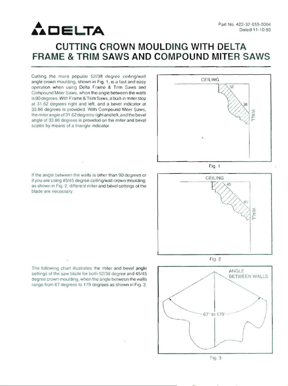
Cutling
angle crown moulding. shown in Fig.
operation when uSing
Compound Miler Saws. when the angle between the
iS90degrees. With Frame & Trim Saws, a built, in
at 31,62 degrees fight and left, and a bevel Indicalor
33.86 degrees is provided. With Compound Miler Saws.
lhe miler angle of 31.62 degrees right and left. and the bevel
angle of 33.86 degrees is provirJed on (he miter and bevel
scales
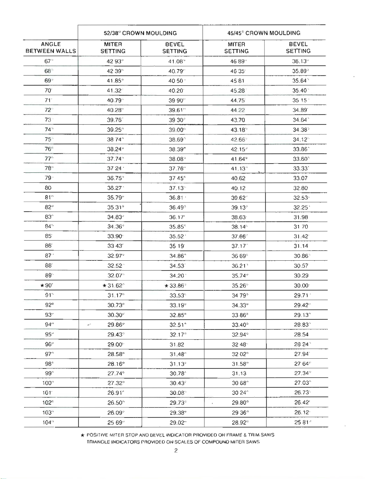
If Ihe angle between the walls is other
il you are using 45/45 degree ceiling/wall crown moulding,
as shown
blade are necessary
the
by
means
in
& TRIM SAWS AND
more
populi1r
of a triangle indicator
Fig.
2,
different miter and bevel seltings
Delta
52/38
rrame
degree
1.
& Trim Saws and
ceiling/wail
is n last and easy
Ulan 90 degrees or
waUs
mllerslop
at
of
Ihe
COMPOliND
CEILING
MITER SAWS
Fig,l
and
The following chart Illustrates the miter
sellings of the
degree crown moulding, when the angle between the walls
range from 67 degrees
saw
blade
for
bolll
10
179 degrees as shown
52/38 degree and
bevel angle
45/45
IJYFig.
3
Fig 2
Fig.
:3
Page 2
52138"
CROWN MOULDING 45/45"
CROWN
MOULDING
ANGLE
BETWEEN
67"
68'"
69'
70'
71'
72"
73 '
74'
75'
76°
77"
78"
79
80
81"
82
8T'
84"
85'
86'
87'
88'
89"
*90'
91"
92° 30.73" 33.1g
93"
94"
95"
96"
9?"
98° 28.16° 31.13"
99~
100"
10'-
102r.
103"
104"
WALLS
J
~
MITER
SETIING
4293"
4239"
41,85"
41,32
40.79"
40.28"
39.76-
BEVEL
SETTING
41,08"
40.79"
4050
40,20'
3990"
39.61"
3930"
'
MITER
SEITING
39.25" 39,00" 43.18"
3874'" 38.69-'
38.24
37.74"
3724
36,75'
36.27'
35.79"
35.31°
34.83'-
3'1,36"
u
.
38.39~
38.08'" 41.64"
37,76"
3745"
37.13'
36.81 .
36.49~
_.
36.1'1'
35.85"
33,90' 35.52 3343'
32.97"
32.52 -
32.0"1"
*31.62"
31.17"
30.30"
29.86'-'
29.43"
3519'
34.86~
34.53'
34.20 . 35,74')
*
33.86'
33.53"
u
32.85"
0
32.51
321
T'
29.00" 31.82
28.58"
27.74"
27.32"
26.91'
31.48"
30,78'
30.43'-
30.08"
26.50" 29.73"
26.09"
2569"
29.38"
29.02"
BEVEL
SETIING
4689'
4635'
4581
45.28
44.75
44.22
43.70
36.13'"
35.89'
35.64"
35.40 .
----_
35
'5'
34.89'
34.6-4'
34,38'
42.66'
42,15
0
34.12"
33.86'
33.60"
41.13 '
40.62
,
3333'
33.07
40.12 32.80
39.62"
39,13"
38.63'
38.14"
37.66'
37.17'
3669('
36.21
'
32.5332,25'
31.98
31
70
31.42'
31.14
30,86-'
30.57
30.29
35.26"
34
79~
34.33
3386
33.40,0
32,94"
3248-'
3202"
31,58"
31.13
68~
30
30
24~
29.80°
2936"
28.92"
u
0
30.00'
29.71 '
29.42"
29.13"
28.83'
28,54
2824"
27,94'
27
6-4"
27.34'"
27
,O3~
26,73"
26.42'
26,12
2581'
..
_-
* POSITIVE MITER STOP AND
TnIANGLE INDICATORS PROVIDED
B17VEL
INDICA10R
ON
SCALES OF COMPOUND MITEn SAWS
PROVIDED
ON FRAME & TRIM SAWS
2
Page 3

ANGLE
BETWEEN
105'
106
107
108'
109'
110
1
112
113
--
114
lIS
116
117
118
119
120
121
122
123'
124 '
125
126'
127
128
129
130'
131
132
133'
134'
135" 14.30"
136'
137"
138'
139"
140'
141"
142'
11
WALLS
-
.
52138
CROWN
MITER
SETTING
2529'
24.89"
1\9
24
24.10 .
2371
23.32
2293
22.5~
22,17
21.79
21,42
21
04
20.67
20.30
19.93
1957
19.20
18,84
18.48
18.13
17.77
1'7.'-12
17.06
1671
1637
1602
15.67
-
1533
MOULDING
I
.
BEVEL
-
SETTING
28.67'
28.31"
27.95"
2759'
27.23'
26.87
26.51
26.15 25.50
25,78
25.42
25.05
24.68'
24.31
23.94
23.57
23.20"
22.83
2246
22.09
21.71
21.34
20.96
2059
20.21
1983
19.45
1907
.
18.69'
45/45"
SETTING
.~
._,
14.99 18.31'
14.65"
17,93"
17,55 .
13,97'" 17.17"
13.63'" 16.79
c
1330
'
12.96"
12.63"
12.30"
11.97:'
16.40'
16.02
15.64"
1525'
14.B7"
............
0
,
CROWN
MITER
MOULDING
BEVEL
SETTING
28.48
28.05'
2762'
25.50'
25
2487'
27.19' 24.56
26.77'
26.34
25.92
I
24.21\
23.93
2361
23.29
2508
2<'\.66
24.25
23,84
23.43
2302
2261
22,21"
~_
.
...,
2297'
22.65 .
2233
22.01
2\.68
21.36
21
2070
21,80 20.38
21.40
21.00
2061
2021
19.81
1942
19.03
18.64
18.25
17.86
1748'
17.09
16.71'
16.32
1594
15.56
15.19
14.81 .
1443"
14.06
136B'
.
.
-
2005
19.72
19.39
19.06
18,72
18.39
18.06
".
17,72
17.39
17.05
16.71 .
1638
16.04
1570
IS.3G
15.02
14.68
14.34"
1400
13.65
1331
19'
03
'
--
3
Page 4

------
52138" CROWN MOULDING
ANGLE MITER BEVEL MITER
BETWEEN WALLS
143"
144')
145'
146'
147"
148~
149'-'
150"
151" 9.05"
152?
153"
154"-
155"
156'
lsr
158"
0
159
160"
161"
162"
163"
164"
165"
166"
16T'
168"
169~
170"
171')
172"
173"
174'-'
175<>
176"
177"
178'
179"
-
SETIING
,
1.64~
11.31"
10.99 '
10.66"
1U.34·
lO.OF
9,69'"
9.37"
8.73~
8.41('
8.09"
7.77'
7.46"
7.14'
6.82"
65P
6.20"
5.88'
5.57" 7.08'
S
26-
4.95'"
4.63"
4.32'
4.01'
3,70'"
3.39' 4.33'
3.08"
277"
2.47" 3.15
0
2.15
c
1.85
1.54~
1.23<'
.92"
.62"
.31" .39
SETTING SETTING
14.48" 13.31'"
~4
09"
13.71 '
13.32"
12.93"
12.54~·
12.16"
11.77" 10
11
38"
10.99"
10.60"
1021"
9.82"
---
9.'l3"
904"
8
65"
8.26"
7.136'
747"
~_.-
6.69'
6.30~
5,90"
551'
5.12'
4.72"
394"
3.54°
Q
2.75"
2.36"
1.97"
1.58~
1.18"
.79"
0
,
45/45" CROWN MOULDING
BEVEL
SETIING
'297"
12.94"
12.57'
12.20"
11,83"
11.46"
11.09"
73"
10.36"
10.00"
9.63"
927"
8.91"
8,55"
8.19"
7,83'
7.'U
1.11"
,
O
12.62"
12.28
11.93"
11.59
1124"
10.89"
1055"
10.20"
9.85"
950
9.15"
8.£30"
81\5"
8.10'
7.75-'
7.40"
6,75" 6.70"
6.39'
603"
568"
5.32~
-
4.96"
4.61"
4.25"
3.90"
3.54"
u
3.19
2.83"
D
2.48
2.12"
1.77"
1.41"
1.06"
71"
.
35<'
-
7.05'
6.35"
6.00'
5.65
530"
4.94"
5,59'
4.24"
3,89'
3.53'"
3.1W
2.83"
2.47'
2.12"
1.77'
1.41"
1.06';
71'
.35 .
4
 Loading...