

Page 1
&
Installation
SKYFiTM Audio System
Operation Guide
This symbol is intended to
alert the user to the
presence of important
operating and maintenance
(servicing) instructions in
the literature accompanying
the appliance.
Page 2
Warning
T o prevent fire or shock hazard, do not expose the boom box to rain or moisture.
For customers in the United States
This device complies with part 15 of the FCC rules. Operation is subject to the following two condition s:
(1) This device may not cause harmful interference, and (2) this device must accept any interference
received, including interference that may cause undesired operation.
Changes or modification s not expressly approved by Delphi could void the user’s authority to operate this
equipment.
Owner’s Record
The model number is located at the bottom and the serial number is located on the la bel on the rear of
the Audio System.
Record the serial number in the spa ce provided below. Refer to these numbers whenever you call upon
your dealer regarding this product.
Model No.: DELPHI SA10001 Serial No.____________________
This symbol is intended to alert
the user to the presence of
uninsulated “dangerous voltage”
within the product’s enclosure
that may be of sufficient
magnitude to constitute a risk of
electric shock to persons.
This symbol is intended to
alert the user to the
presence of important
operating and maintenance
(servicing) instructions in
the literature accompanying
the appliance.
Page 3

SKYFi
TM
Audio System Set-Up……….…………….......…….….4
Antenna Set-Up……………......................…….........…...….….6
Using the SKYFi
TM
Audio System………..………..…..…...……8
Precautions………….. …………………………...….…..……...10
Troubleshooting…………………………………....……..……...11
Maintenance……………………………………...………..….....11
Specifications……………….………………………...….……...12
Table of contents
3
Page 4
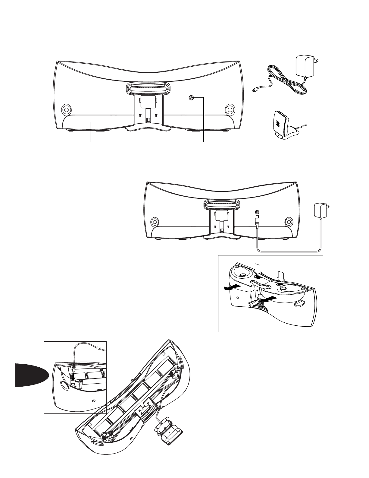
SKYFiTM Audio System Set-Up
Your SKYFiTM Audio System Kit contains the following components:
Set-up your SKYFi
TM
Audio System as follows:
1. Connect the supplied 12V
DC power adapter to the
socket on the rear of the Audio
System, and the other end to a
wall outlet.
2. Connect the XM Antenna to the antenn a jack located
inside the battery and antenna cable storage compartment located on the bottom of the Audio System. The
cover must first be removed by pressing down on the
two tabs with your thumbs and then sliding away from
the front of the Audio System. The antenna cable can
either be completely wound around the tabs in the
compartment, leaving just enough cable to attach
the antenna to the four tabs on the back
of the Audio System, or the entire 20 foot
cable can be used to position the
antenna away from the Audio System for
better reception. Lining up all six tabs and
then sliding the panel towards the front of
the unit until a click is heard will reattach
the panel. Make certain that all six tabs
are engaged and the rear of the panel is
aligned with the rear cover.
Battery compartment an d
antenna cable storage
4
12V. DC jack
12V. DC Adaptor
Antenna
Page 5

Using the SKYFiTM Audio System with batteries
The SKYFiTM Audio System can be used with batteries (not supplied) to allow you to listen
to XM outdoors or in other locations without access to an A.C. power source. Alkaline or
rechargeable NiCD batteries are recommended. Battery life will vary depending on how the
system is operated and the type of batteries being
used. It is recommended that the AC Adapter be
the primary power source for the SKYFi
TM
Audio
System in order to preserve battery life.
1. Disconnect the power adapter from the
back of the Audio System.
2. Remove the battery and antenna cable
storage compartment cover, as described in
#2 in the previous section.
5. If the display reads “ANTENNA” after powering up, check that the antenna connection
is secure and completely pushed in. Next, change channels (from 0 to 1 or from 1 to 0 if
the receiver is not authorized yet.) If the “ANTENNA” message remains, power down the
radio, unplug the antenna, and look for any obvious damage in the connector, ja ck, or
antenna cable. If no damage is detected, reconnect the antenna, turn the unit back on,
and change channels again. If the message still appears, contact your retailer.
6. If the display reads “NO SIGNAL” after powering up, follow the instructions in the
Antenna Set-up Section.
3. Insert the SKYFi
TM
Receiver (sold
separately) by first pressing in on the back of
the black inset cradle in the Audio System and
then letting the cradle tilt forward, carefully slide
the SKYFi
TM
Receiver down into the tray so that
the alignment tabs on the sides of the tray lineup with the slots on SKYFi
TM
and the connector
is completely seated. Push on the top center
above the display of the SKYFi
TM
Receiver so
that it tilts back into the Audio System until a
click is heard. The SKYFi
TM
Receiver can be
removed by reversing this process.
4. Power up the SKYFi
TM
/Audio System combination by powering up
the SKYFi
TM
R eceiver using the power button on the receiver or on
the remote control.
5
Page 6

3. Insert six D size (R20) batteries into the battery
compartment. Make sure that the batteries are facing the
correct direction by verifying that the positive (+) and
negative (-) symbols in the battery compartment match up
with the same symbols on the batteries.
4. It is recommended that the batteries be removed
when it is not in use for an extended period of time.
Antenna Set-up
Positioning the XM Antenna
The antenn a that comes with the SKYFiTM Audio Syste m is a high-gain antenna that can
receive XM’s signal from XM’s satellites and/or, depending on where you live, XM’s land
based repeaters. It is recommended that the antenna be positioned near a south-facing
window or outdoors with a clear view of the southern sky in order to receive the satellite
signal. In some cases, it will be possible to receive XM’s signal through standard home
walls or a roof.
To position your antenna, first set up the Audio System as described earlier in this manual.
Next, position the antenna until you receive the strongest possible satellite signal. If the
satellite signal is not available, you can optimize it for a terrestrial signal (where available).
Installing the XM Antenna on the rear of the Audio System.
When outdoors with a view of the southern sky, or in an area of repeater coverage, or
when receiving a strong signal indoors, you can conveniently mount the antenn a directly
on the back of the Audio System.
1. Remove the battery and antenna cable storage compartment cover as previously
described, wind the antenna around the two cable hooks, leaving several inches of cable
free, and replace the cover.
6
Optimizing Antenna Position/Signal
Press the “Power” button on the SKYFiTM Receiver to start the Audio System.
Press the “menu” button.
Using the scroll wheel, turn the wheel until
“Antenna Aiming” is highlighted.
With “Antenna Aiming” still highlighted, press the
“enter” button found in the center of the scroll wheel.
The display will show the strength of the satellite and/
or terrestrial signals. The antenna sign al strength is
indicated by the number of filled bars.
Page 7

4. Place the antenna so that the base is flush with the
back of the Audio System, and then slide down approximately 3/8ths of an inch so that the tab at the base of the
Audio System lines up with the slot in the bottom of the
antenna.
5. Position the antenn a by pivoting the half with the XM
logo away from the back of the Audio System and turning
the entire Audio System until you get the strongest signal.
6. Use the “Antenna Aiming” screen as described in the
previous section to optimize the antenna tilt angle and
position.
If you are unable to receive a signal, then position the
antenna as described in one of the next two sections.
7
Indoor installation on a flat surface
To ai m your antenna at the satellite:
1. Set antenna flat against its ba se on a flat (horizontal) surface.
2. Turn the base of the antenna so that the XM logo is
facing to the south.
3. Use the “Antenna Aiming” screen to optimize antenna
tilt angle and position.
4. If necessary, experiment with different locations near
a south-facing window or outside.
Your antenna comes with 20 feet of cable. If that is not
sufficient to locate the antenna where there is a strong
XM signal, purchase a 50-foot cable extension (Delphi
model number SA10006) from your SKYFi
TM
retailer. Up
to eight extensions can be used together for up to 40 0
total feet of cable.
2. Fold the antenna down flat against its base.
3. Position the antenna so that the XM logo is upside down, then place the antenna base
against the back of the Audio System so that the four pegs line up with the four slots in the
antenn a base.
Outdoor installation or indoor wall mounting
The antenn a can also be attached vertically to an external or intern al wall if that is more
convenient than placing it on a horizontal surfa ce.
1. Holding your antenna up, find a wall location that ensures a strong sign al. It is re com-
mended that you use an extension cord to temporarily locate your SKYFi
TM
Home stand
outdoors while optimizing the antenna location with the “ Antenna Aiming” screen.
Page 8

2. Attach four screws to the wall using the screw-locator pattern in figure 6. Photocopy the
pattern to use as a template. Use screws with head sizes small enough to fit in the
center of each of the four holes but large enough not to pop out of the elongated
sections. Leave 1/8 inch of the screw shanks behind the heads sticking out of the wall.
3. Tilt the antenna fully back on the ba se. Place the antenna base on the four screw heads
with the antenn a pivot at the top. and pull down approximately 1/4 inch until the base is
firmly secured. Note that the XM logo will be upside down when the antenna is properly
installed.
4. Tilt the antenna away from the wall/base until the signal is optimized.
Note: Do not cut the antenna cable and attempt to splice it or attach alternative connectors or cable. The cable and connectors used in your SKYFi
TM
Home Adapter Kit are
specially chosen and atta ched at the factory to ensure that they will work with XM’s unique
frequency band. Use an XM-approved extension kit (Deplhi model number SA10006) with
your SKYFi
TM
system.
8
Photocopy this diagram of the screw-locator pattern on the bottom of your XM
Antenna to use as a template for wall attachment.
Using the SKYFiTM Audio System
Once the SKYFiTM Audio System is set-up and the SKYFiTM R eceiver installed, the
complete set-up can be controlled as described in the SKYFi
TM
Operating Guide.
Unique SKYFi
TM
Audio System features include the following:
Page 9

9
V olume
Volume can be adjusted using the volume knob on the SKYFi
TM
Audio System. In addition, when the SKYFiTM Receiver is connected to the Audio System, the + and – controls on the remote
control can also be used to increase (+) and decrease (-) the
volume.
If you also use your SKYFi
TM
Receiver with a vehicle adaptor kit or home adaptor kit, the
SKYFi
TM
Receiver will remember the volume level previously set when connected to the
Audio System and return to that setting the next time the Audio System is used.
Note that the Line Out Level cannot be reset while the SKYFi
TM
Receiver is in the Audio
System since the volume control should be used to control the audio output instead. If the
line out setting is adjusted while in a car cradle or home stand and the SKYFiTM Receiver is
later reconnected to the Audio System, it will automatically return to the prior setting the
next time it is used in a vehicle adaptor or home adaptor.
Bass & Treble
Bass and treble can be adjusted by pressing the “menu” button, selecting “Bass + Treble,”
and then setting them in the same manner as other menu functions.
This feature only appears and only applies when the SKYFi
TM
Receiver is seated in the
Audio System. If the SKYFi
TM
Receiver is removed and used in a vehicle adaptor or home
adaptor, the bass and treble settings out of SKYFi
TM
will be “flat”, or “zero”, since the audio
signal will be processed by the vehicle or home audio systems. When SKYFi
TM
is returned
to the Audio System, it will return to the previously used bass and treble settings.
Headphones
The SKYFiTM Audio System has a “headphone” jack conveniently located next to the
“volume” control on the front of the unit. Many popular styles and types of headphones or
“ear buds” can be used as long as their plugs and/or adaptors fit the industry standard 3.5
mm diameter stereo jack.
Hearing damage from loud noise is almost undetectable until it is too late. Your
hearing can adapt to higher volumes of sound. Sound that seems normal can be loud
and harmful to your he aring. Take pre caution s by adjusting the volume control on your
audio system to a safe sound level before your hearing adapts to it.
To help avoid hearing loss or damage do the following:
1. Adjust the volume control to the lowest setting.
2. Increase volume slowly until you hear comfortably and clearly.
Page 10

Precautions:
1. On power sources.
For AC operation, it is recommended that only the supplied AC power adaptor is used; If
you need to use another one, make sure it is a 12V, 1500mA DC adaptor with a unified
polarity-type jack.
The satellite radio unit (SKYFi
TM
) is not disconnected from the AC power source (mains)
as long as it is connected to the wall outlet, even if the satellite radio unit (SKYFi
TM
) itself
has been turned off or detached.
Un plug the AC power adaptor from the wall outlet when it is not used for an extended
period of time.
For battery operation, use six D size (R20) batteries.
When the batteries are not being used, remove them to avoid possible damage that can
be caused by battery leakage or corrosion.
The icon indicating operating voltage, power consumption, etc. is located next to the
power jack on the rear cover.
2. On placement.
Do not place the SKYFi
TM
Audio System on an inclined or unstable surface.
Do not place anything within 1/2 inch of the side of the cabinet. The audio/ventilation
ports must be unobstructed for the SKYFi
TM
Audio System to operate properly and prolong
the life of its components.
Since a strong magnet is used for the speakers, keep personal credit cards using
magnetic coding or spring-wound watches away from the unit to prevent possible damage
from the magnetic fields.
4. Do not immerse in water
This product is not meant to be immersed in water or come in continuous contact
with water.
Before opening or shutting the SKYFi
TM
Receiver cradle or battery compartment panel,
be sure to wipe off water, dust, or sand on the outside of the unit.
If the SKYFi
TM
Audio System is splashed with salt water, wipe clean with a damp cloth,
and then dry with a soft dry cloth. Do not wash under running water; do not use soap or
detergent; do not dry with an electric hair dryer.
If the SKYFi
TM
Audio System is left in a car parked in the sun, be sure to choose a
location in the car where the unit will not be subjected to the direct rays of the sun.
10
Page 11

11
The supplied AC power adaptor is not water resistant. To prevent shock hazard, avoid
using the SKYFi
TM
Audio System near water during AC operation.
Water in the headphone jack may cause rusting and possible malfunction.
Troubleshooting
General:
1. The power is not on.
Connect the AC power adaptor to a wall outlet securely and make sure the
wall outlet has the 110V AC output.
Make sure the batteries are inserted correctly.
Replace all the batteries with new ones if they are weak.
2. There is no audio.
U nplug the satellite radio unit (SKYFi
TM
) from the audio system and re-insert the SKYFi
TM
unit..
3. Noise is heard coming through the Audio system.
Someone is using a portable telephone or other equipment that emits radio waves
near the antenna (~2.3GHz). To solve this problem move the portable telephone etc.,
away from the unit.
Maintenance
To clean the cabinet panel and controls, use a soft cloth slightly moistened with a mild
detergent solution. Do not use any type of abrasive pad, scouring powder, or solvent,
such as alcohol or benzene.
Note: Unplug the AC power adaptor during the cleaning to avoid any electrical shock
hazard.
Page 12

Specifications
ITEM
UNIT
SPECIFICATION
REMARK
Nominal Limited
1 W > 4 > 3.5 Rated Output (10%) at 1 KHz
Continuous
Average power
Output
2 % > 0.6 > 1.0 Output: 0.5w
T otal Harmonic
Distortion
Frequency:
70Hz - 20KHz
2 % > 0.6 > 1.0 Output: 0.5w
T otal Harmonic
Distortion
Frequency:
70Hz - 20KHz
3 mV 180 140 ~ 235 Line Input
Sensitivity
Frequency:
70Hz~20KHz
12
4 Hz 65 ~ 22K 70 ~ 20K -3dB
Frequency
Response
0dB: 0.775V/1KHz
5 dB >65 >60 Level 1 0db: 2.0V/1KHz
Signal T o Noise
Ratio
6 dB >45 >40 Level 1 0db: 2.0V/1KHz
Channel
Separation
Input: Short
7 Ohm Frequency 1KHz
Input
Impedance
- - Normal Input
- - Floating Input
>4.7K >4.5K Line Input
8 mV 3 5 Input: ShortMax noise Ratio
9 mV 3 5 Input: ShortMax noise Ratio
9 V 7 ~ 16 7.5 ~ 15 Operation fine
Battery Power
Range
10 mm __18 3/4”_ W. ___7”__ H. ______5 5/16”_____ D.
Dimension
Page 13

Delphi Corporation
1441 West Long Lake Road
Troy, MI 48098-5090
USA
Technical Assistance: [1] 877.GO DELPHI
Customer Service: [1] 866.227.9071
www.delphi.com
The SKIFiTM name, XM name, and related logos
are trademarks of XM Satellite Radio Inc.
2002 Delphi Corporation. All rights reserved.
DAO-02-E-103
 Loading...