

Page 1
Multec 3.5 Top Feed Fuel Injector
Application Manual
Fuel Systems Applications Engineering
Delphi Energy & Chassis Systems
5500 W. Henrietta Rd.
P.O. Box 20366
Rochester, New York 14602 USA
Delphi Energy and Chassis Systems 2005
Page 2

Page 3

Multec 3.5 Fuel Injector Application Manual Revision Summary
Multec 3.5 Top Feed Fuel Injector Application Manual
Release/Revision Summary Sheet
CHANGE NO. DATE REASON FOR CHANGE PAGE(S)
Issued April 2004 N/A N/A
1 July 2005 Replaced “J-spray…” with “J-2715 (Draft)” in section
1.9.4.2
1 Nov. 05 Added shutdown throttle closure note to section 8.4.4 8-4
1 Changed ‘and applicable’ to ‘any applicable’ in
section 1.9.1
1 Nov 05 Added reference to Worldwide Emissions Standards
booklet to section 2.2.3 and 1.9.3
1 Nov 05 Updated MTBE phase out plans in section 2.2.6.2 2-10
1 Nov 05 Updated gasoline sulfur requirements in section
2.2.6.3.4
1 Nov 05 Re-worded section 2.2.7.3 for clarity 2-18
1 Nov 05 Corrected return and inlet locations in Figure 2-5 2-23
1 Nov 05 Added extended tip description to section 3.2.2 and
view to Figure 3-2
1 Nov 05 Changed “core” to “valve” in section 3.2 3-1
1 Nov 05 Added rotational orientation note to section 3.3.5 3-6
1 Nov 05 Reworded section 3.5.1 for clarity 3-11
1 Nov 05 Added Zener diode voltage range and injector flow
test for vehicle calibration note to section 3.6.3
1 Nov 05 Revised calculation example from max flow to min
flow in section 3.7
1 Nov 05 Added J-2715 to section 3.8 3-21
1 Nov 05 Revised 96% spray volume for dual spray to 90% in
section 3.8.2
1 Nov 05 Updated Figure 3-12 to current data format 3-26
1 Nov 05 Removed word “serviceable” from filter requirements
in section 3.12
1 Nov 05 Changed “Component Technical Specification” to
“Engineering Product Specification” in section 3.16
1 Nov 05 Added “absolute” to manifold air pressure in Table
3-2
1 Nov 05 Revised Figure 6-1 to include o-ring installation tool 6-3
1 Nov 05 Added section 6.4 and Figure 6-2 – injector
installation into fuel rail and renumbered remaining
sections
1 Nov 05 Added reference to Figure 6-1 in section 4.3 4-8
1 Nov 05 Added “total” to A/F variation” in section 3.10.2 3-33
1 Nov 05 Added section 5.2.3.3 “Variable Fuel Pressure
Compensation”. Renumbered remaining sections.
1 Nov 05 Added reference to terminal lubricant (section 7.5) in
Table 6-1
1 Nov 05 Added reference to terminal lubricant (section 7.5) in
section 4.4.4
1 Nov 05 Added reference to Figure 6-1 in section 6.5 6-6
1 Nov 05 Added metal fuel line recommendation to section
7.3.5
1-7
1-5
1-6, 2-8
2-12
3-3, 3-4
3-13
3-19
3-22
3-36
3-39
3-40
6-4
5-10
6-2
4-14
7-5
Delphi Energy and Chassis Systems
Revision: 11/05-1
Page 4

Multec 3.5 Fuel Injector Application Manual Revision Summary
1 Nov 05 Renumbered pages in section 4 starting at 1 4-1
1 Nov 05 Changed dwell time from 1 hr to 0.5 hr and duration
9-3
from 240 hours to 120 hours in section 9.3.2.1
Delphi Energy and Chassis Systems
Revision: 11/05-01
Page 5

Multec 3.5 Fuel Injector Application Manual Table of Contents
Table of Contents
1. 0 INTRODUCTION ................................................................................1-1
1.1 SCOPE OF DOCUMENT .....................................................................................................................1-1
1.2 CLASSIFICATION .............................................................................................................................. 1-1
1.3 DOCUMENT MANAGEMENT ............................................................................................................... 1-1
1.3.1 Document Release and Updates .........................................................................................1-1
1.4 COMMERCIAL CONSIDERATIONS .......................................................................................................1-1
1.5 OBJECTIVES OF THIS MANUAL .......................................................................................................... 1-1
1.6 HOW THIS MANUAL IS ARRANGED..................................................................................................... 1-2
1.7 CONVENTIONS USED IN THIS MANUAL............................................................................................... 1-4
1.8 HYPERLINKS....................................................................................................................................1-5
1.9 APPLICABLE DOCUMENTS ................................................................................................................1-5
1.9.1 Order of Precedence ............................................................................................................ 1-5
1.9.2 Government Documents ......................................................................................................1-5
1.9.3 Other Delphi Reference Documents ....................................................................................1-5
1.9.4 Industry Documents .............................................................................................................1-6
1.9.5 Useful Web Sites..................................................................................................................1-6
2. 0 FUNDAMENTALS .............................................................................. 2-1
2.1 GENERAL ........................................................................................................................................2-1
2.2 ENGINE COMBUSTION FUNDAMENTALS ............................................................................................. 2-2
2.2.1 Air/Fuel Ratio Effects on Combustion ..................................................................................2-3
2.2.2 Fuel Atomization................................................................................................................... 2-7
2.2.3 Fuel Spray Characteristics and Injection Timing.................................................................. 2-8
2.2.4 Benefits of Electronic Fuel Injection Over Other Types of Fuel Systems ............................2-9
2.2.5 Impact of Transient Conditions on Combustion ................................................................... 2-9
2.2.6 Impact of Fuel Composition................................................................................................2-10
2.2.7 Engine-Vehicle Environment..............................................................................................2-14
2.2.8 Maximum Power Fueling Requirements ............................................................................2-19
2.2.9 Injector Flow Tolerances ....................................................................................................2-20
2.3 FUEL FLOW CONSIDERATIONS........................................................................................................2-20
2.3.1 Minimum Fuel Pump Flow Output......................................................................................2-21
2.3.2 Nominal Fuel Pump Output ................................................................................................ 2-21
2.3.3 Fuel Pump Check Valve Requirements .............................................................................2-22
2.3.4 Pressure Regulator Gain/Considerations (Vacuum Biased).............................................. 2-22
2.4 IMPACT OF EMISSIONS REQUIREMENTS .......................................................................................... 2-23
2.4.1 The Impact of Emission Requirements on Fuel Control Systems .....................................2-23
2.4.2 Fuel Injector Design Effects on Evaporative Emissions.....................................................2-25
2.4.3 Impact of Canister Purge on Engine Fueling .....................................................................2-26
2.4.4 Impact of EGR and PCV on engine fueling........................................................................ 2-27
2.4.5 Injector Flow Characterization............................................................................................ 2-27
3. 0 PRODUCT DESCRIPTION.................................................................3-1
3.1 SCOPE............................................................................................................................................3-1
3.2 GENERAL DESCRIPTION ...................................................................................................................3-1
3.2.1 Appearance .......................................................................................................................... 3-3
3.2.2 Exterior Outline..................................................................................................................... 3-3
Delphi Energy and Chassis Systems
Revision: 11/05-1 i
Page 6

Table of Contents Multec 3.5 Fuel Injector Application Manual
3.2.3
Usage Definition ................................................................................................................... 3-3
3.2.4 Failure Diagnostics...............................................................................................................3-3
3.3 PHYSICAL SPECIFICATIONS ..............................................................................................................3-3
3.3.1 Dimensions........................................................................................................................... 3-3
3.3.2 Mass ..................................................................................................................................... 3-5
3.3.3 Identification and Markings ..................................................................................................3-5
3.3.4 Internal Components ............................................................................................................ 3-5
3.3.5 Injector Retaining Clip ..........................................................................................................3-6
3.3.6 Seal rings..............................................................................................................................3-7
3.4 CUSHION SEAL INJECTOR DESIGN ....................................................................................................3-8
3.5 INJECTOR DESIGN ...........................................................................................................................3-8
3.5.1 Dual Spray Fuel Injector.....................................................................................................3-11
3.6 INJECTOR CONTROLS – CONTROLLER DRIVE CIRCUIT ..................................................................... 3-12
3.6.1 Minimum Operating Voltage (MOV) ................................................................................... 3-12
3.6.2 Driver Considerations.........................................................................................................3-12
3.6.3 Driver Circuit Clamping Voltage ......................................................................................... 3-13
3.6.4 Injector Polarity................................................................................................................... 3-13
3.7 INJECTOR FLOW RATE SIZING ........................................................................................................3-13
3.8 INJECTOR TARGETING, PLACEMENT AND CONE ANGLE....................................................................3-21
3.8.1 Targeting ............................................................................................................................3-21
3.8.2 Cone Angle......................................................................................................................... 3-22
3.8.3 Spray Atomization ..............................................................................................................3-23
3.9 PULSE-WIDTH LIMITS .................................................................................................................... 3-27
3.9.1 Minimum Pulse-Width (MPW) ............................................................................................ 3-28
3.9.2 Tailbiting .............................................................................................................................3-30
3.10 LINEAR AND WORKING FLOW RANGE ..................................................................................... 3-31
3.10.1 Linear Range......................................................................................................................3-31
3.10.2 Working Flow Range .......................................................................................................... 3-33
3.11 TIP LEAKAGE ........................................................................................................................3-34
3.11.1 Total Fuel System Tip Leakage Monte Carlo Analysis ......................................................3-35
3.12 CONTAMINATION RESISTANCE ............................................................................................... 3-36
3.13 DYNAMIC AND STATIC FUEL FLOW SPECIFICATIONS................................................................ 3-36
3.13.1 Flow Test Fluid Specification .............................................................................................3-37
3.14 NOISE ..................................................................................................................................3-38
3.15 ELECTRICAL SPECIFICATIONS ................................................................................................3-38
3.15.1 Solenoid Coil Specifications...............................................................................................3-38
3.15.2 Avalanche Energy ..............................................................................................................3-38
3.16 ENVIRONMENTAL CONDITIONS...............................................................................................3-39
3.16.1 Hot Fuel Handling...............................................................................................................3-39
3.16.2 Environmental Exposure ....................................................................................................3-40
4. 0 SYSTEM INTERFACE........................................................................4-1
4.1 GENERAL ........................................................................................................................................4-1
4.1.1 Interface Control Document .................................................................................................4-2
4.2 MECHANICAL INTERFACES ............................................................................................................... 4-3
4.2.1 Locating the Fuel Injector .....................................................................................................4-3
4.2.2 Orienting the Injector ............................................................................................................ 4-4
4.2.3 Vibration Levels....................................................................................................................4-5
4.2.4 Fuel Supply System Interface ..............................................................................................4-7
ii Delphi Energy and Chassis Systems
Revision: 11/05-01
Page 7

Multec 3.5 Fuel Injector Application Manual Table of Contents
4.3 SEAL RINGS.....................................................................................................................................4-8
4.4 ELECTRICAL INTERFACE................................................................................................................... 4-9
4.4.1 Electromagnetic Compatibility..............................................................................................4-9
4.4.2 Wire Routing......................................................................................................................... 4-9
4.4.3 Fuel Injector Polarity........................................................................................................... 4-10
4.4.4 Fuel Injector Connector ...................................................................................................... 4-11
4.4.5 Controller............................................................................................................................4-14
5. 0 SOFTWARE .......................................................................................5-1
5.1 GENERAL ........................................................................................................................................5-1
5.2 CONTROL ALGORITHMS ................................................................................................................... 5-2
5.2.1 Injection Methods .................................................................................................................5-2
5.2.2 Open Loop Injector and Fuel Rail Characterization ............................................................. 5-4
5.2.3 Open-Loop Characterization ................................................................................................ 5-9
5.2.4 Closed-Loop Corrections ...................................................................................................5-14
5.2.5 Fuel Injection Timing ..........................................................................................................5-15
5.3 DIAGNOSTICS ................................................................................................................................5-17
5.3.1 Fuel Trim Diagnostics......................................................................................................... 5-17
5.3.2 Oxygen Sensor Diagnostics...............................................................................................5-18
5.3.3 Catalytic Converter Diagnostics ......................................................................................... 5-18
5.3.4 Injector Driver Diagnostics .................................................................................................5-18
5.3.5 Engine Misfire Diagnostics.................................................................................................5-18
5.3.6 Factors Affecting Engine Diagnostics ................................................................................5-19
6. 0 PRODUCT HANDLING ......................................................................6-1
6.1 PACKING PROCEDURES ...................................................................................................................6-3
6.2 RECEIVING AND STORAGE................................................................................................................ 6-4
6.3 MOVEMENT WITHIN THE PLANT ........................................................................................................ 6-4
6.4 INSTALLATION IN FUEL RAIL ............................................................................................................. 6-4
6.5 INSTALLATION ON THE ENGINE..........................................................................................................6-5
6.6 COMPONENT ASSEMBLY BEST PRACTICES ....................................................................................... 6-8
6.7 MAINTENANCE, SERVICE AND REPAIR .............................................................................................. 6-9
6.7.1 Diagnosing Malfunction Codes ............................................................................................6-9
6.7.2 Replacement Techniques ....................................................................................................6-9
6.7.3 Adjustments........................................................................................................................ 6-11
6.7.4 Interchangeability ...............................................................................................................6-11
6.8 SUPPORT OF COMPONENT AFTER SALE..........................................................................................6-11
7. 0 RECOMMENDATIONS AND PRECAUTIONS...................................7-1
7.1 TEMPERATURE ................................................................................................................................7-1
7.2 DURABILITY.....................................................................................................................................7-2
7.2.1 Injector Characteristics.........................................................................................................7-3
7.3 WEAR AND CONTAMINATION ............................................................................................................ 7-3
7.3.1 Internal Corrosion.................................................................................................................7-3
7.3.2 External Exposure ................................................................................................................ 7-3
7.3.3 Plugging................................................................................................................................7-4
7.3.4 Contamination Resistance ...................................................................................................7-4
7.3.5 Fuel System Generated Contamination ............................................................................... 7-5
7.3.6 Maximum Fuel Pressure ......................................................................................................7-5
Delphi Energy and Chassis Systems
Revision: 11/05-1 iii
Page 8

Table of Contents Multec 3.5 Fuel Injector Application Manual
7.3.7
Injector Storage .................................................................................................................... 7-5
7.4 PREVENTING ENGINE HYDRO-LOCK ..................................................................................................7-6
7.4.1 Engine Prime Pulse at Start .................................................................................................7-6
7.4.2 Vehicle Assembly Fuel System Prime .................................................................................7-7
7.5 INJECTOR HARNESS CONNECTOR – CORROSION ..............................................................................7-7
8. 0 TESTING RECOMMENDATIONS AND PRECAUTIONS ..................8-1
8.1 DYNAMOMETER TESTING .................................................................................................................8-1
8.1.1 Cylinder-to-Cylinder Distribution ..........................................................................................8-1
8.2 DURABILITY TESTING ....................................................................................................................... 8-1
8.3 DYNAMIC VEHICLE TESTING ............................................................................................................. 8-2
8.4 STANDARD VEHICLE DEVELOPMENT TESTS.......................................................................................8-2
8.4.1 Hot Fuel Handling................................................................................................................. 8-2
8.4.2 Spray Effect on Emissions ...................................................................................................8-3
8.4.3 Cold Driveability and Startability ..........................................................................................8-3
8.4.4 Crank vs. Leak .....................................................................................................................8-4
8.4.5 Altitude Driveability and Emissions ...................................................................................... 8-4
8.4.6 Low Pulse-Width Fueling Accuracy...................................................................................... 8-4
8.4.7 Driveability Index Fuel Sensitivity......................................................................................... 8-4
8.4.8 Spark Plug Fouling Tests .....................................................................................................8-5
8.4.9 Voltage Sensitivity ................................................................................................................ 8-5
8.4.10 Manifold Pressure Sensitivity ............................................................................................... 8-5
8.4.11 Standard Durability Tests .....................................................................................................8-5
8.4.12 Icing Tests ............................................................................................................................ 8-5
8.4.13 Production Limit Verification Tests....................................................................................... 8-5
9. 0 VALIDATION REQUIREMENTS ........................................................9-1
9.1 GENERAL ........................................................................................................................................9-1
9.2 VALIDATION TESTS ..........................................................................................................................9-1
9.2.1 Preliminary Physical Analysis .............................................................................................. 9-2
9.3 ENVIRONMENTAL EXPOSURE............................................................................................................ 9-2
9.3.1 External Corrosion................................................................................................................9-2
9.3.2 Temperature.........................................................................................................................9-3
9.3.3 Life Cycling ...........................................................................................................................9-3
9.3.4 Mechanical Integrity .............................................................................................................9-4
9.3.5 Overpressurization ...............................................................................................................9-5
9.3.6 Over-voltage.........................................................................................................................9-5
9.3.7 Injector Noise .......................................................................................................................9-6
9.3.8 Note on Additional Exposures..............................................................................................9-6
9.4 VERIFICATION................................................................................................................................. 9-6
10. 0 APPENDIX......................................................................................10-1
10.1 INTRODUCTION. ....................................................................................................................10-1
10.2 MULTEC 3.5 FUEL INJECTOR SYSTEM CUSTOMER COMPONENT CHECKLIST ............................ 10-2
10.3 COMPONENT APPLICATION CHECKLIST ..................................................................................10-8
10.4 COMPONENT ASSEMBLY BEST PRACTICES........................................................................... 10-12
10.5 GLOSSARY OF TERMS AND ABBREVIATIONS..........................................................................10-17
11. 0 INDEX.............................................................................................11-3
iv Delphi Energy and Chassis Systems
Revision: 11/05-01
Page 9

Multec 3.5 Fuel Injector Application Manual Table of Contents
Tables
Table 2-1 - Stoichiometry of Alternate Fuel Blends .................................................................................2-4
Table 3-1 Solenoid Electrical Properties................................................................................................ 3-39
Table 3-2 - Injector Environmental Operating Conditions...................................................................... 3-39
Table 6-1 – Multec 3.5 Injector Handling ................................................................................................. 6-2
Table 6-2 - Recommended seal ring lubricants.......................................................................................6-8
Table 8-1 - Injector tip soak temperature vs required fuel pressure........................................................8-3
Table 9-1 - Potential Injector Test Fuels..................................................................................................9-4
Table 9-2 - Injector Verification Matrix Template ..................................................................................... 9-7
Figures
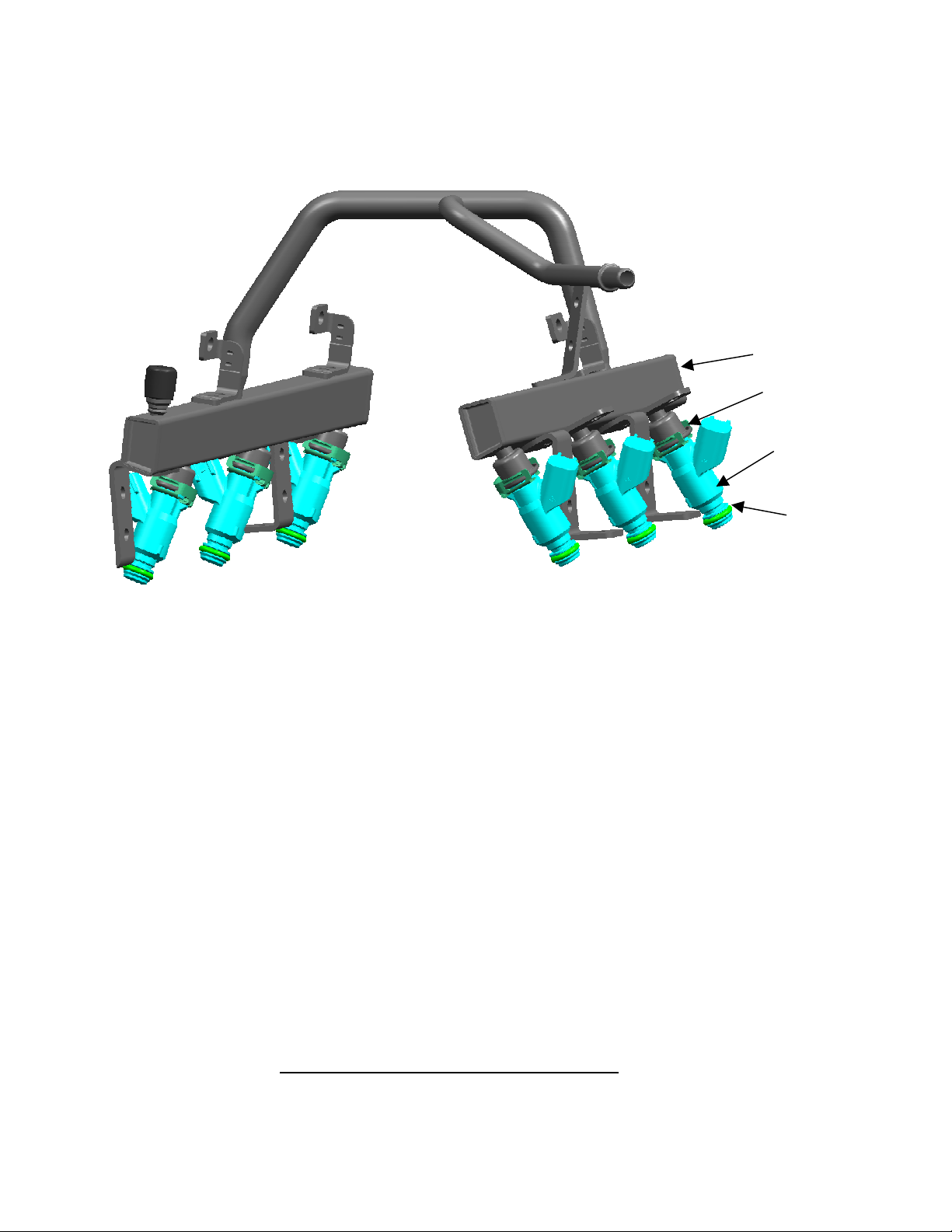
Figure 2-1- Engine Fuel System (shown is a demand fuel rail for a V6 application)............................... 2-2
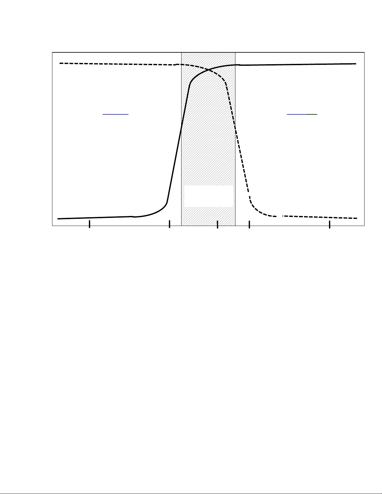
Figure 2-2 - Air Fuel Ratio Effect on Catalytic Converter Efficiency ........................................................ 2-6
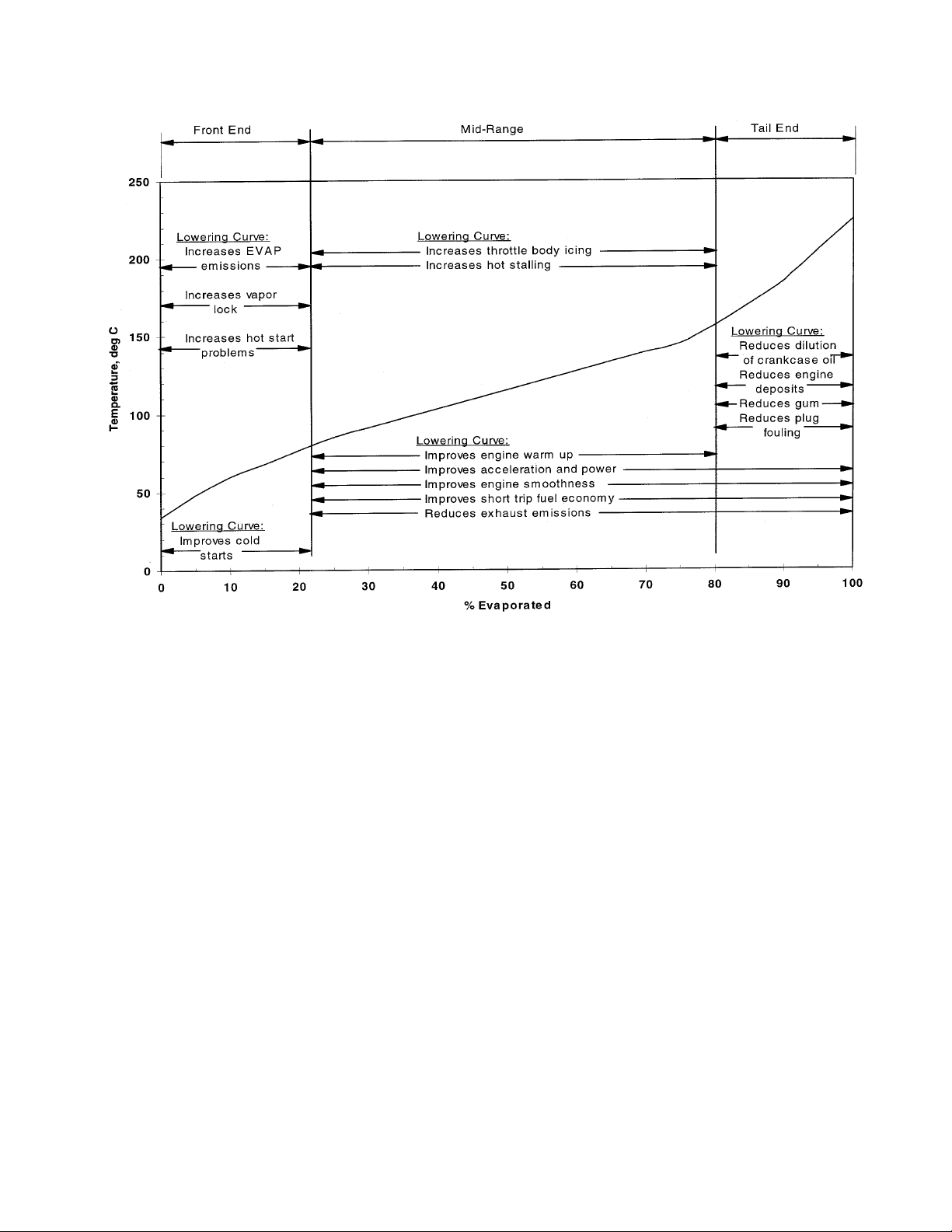
Figure 2-3 - Fuel Distillation Curve vs Temperature..............................................................................2-13
Figure 2-4 - 50% Vapor / Liquid Ratio vs RVP, Fuel and Pressure.......................................................2-17
Figure 2-5 - Fuel Pressure Regulator and Gain Calculation.................................................................. 2-23
Figure 2-6 - Engine Management System Open Loop vs Closed Loop System Architecture............... 2-24
Figure 2-7 - Catalytic Converter Efficiency vs Air/Fuel Ratio................................................................. 2-24
Figure 2-8 California Tailpipe Emissions Limits.....................................................................................2-25
Figure 2-9 - Evaporative Emissions Regulations..................................................................................2-26
Figure 3-1 - Top Feed Port Fuel Injection................................................................................................3-2
Figure 3-2 - Multec 3.5 Fuel Injector Dimensions – Seal ring design. (For exact dimensions, refer to
Delphi Injector Outline Drawing).......................................................................................................3-4
Figure 3-3 – Multec 3.5 Fuel Injector Dimensions – Cushion seal / Face seal design (For exact
dimensions, refer to Delphi Injector Outline Drawing. ...................................................................... 3-4
Figure 3-4 - Injector Identification and Markings......................................................................................3-5
Figure 3-5 Multec 3.5 Internal Components ............................................................................................3-6
Figure 3-6 -Injector Retaining Clip Designs ............................................................................................. 3-7
Figure 3-7 - Multec 3.5 Magnetic Circuit................................................................................................3-10
Figure 3-8 - Multec 3.5 Fuel Flow Path.................................................................................................. 3-10
Figure 3-9 - Dual Spray Injector.............................................................................................................3-11
Figure 3-10 - Injector Targeting .............................................................................................................3-21
Figure 3-11 - Dual Spray Injector Separation and Orientation Angle .................................................... 3-25
Figure 3-12 - Sample Single and Dual Spray Injector Patternator Results ........................................... 3-26
Figure 3-13 Injector Opening and Closing Response............................................................................ 3-27
Figure 3-14 - High Pulse-Width Flow Effects. Static Occurs at 10 msec (rep. rate = 10 msec)...........3-29
Figure 3-15 - Low Pulse-Width Flow Effects. (Rep. rate = 10msec) ...................................................3-29
Figure 3-16 - Injector Flow Curve Tailbiting...........................................................................................3-31
Figure 3-17 - Linear Range....................................................................................................................3-32
Figure 3-18 - Injector Working Flow Range ........................................................................................... 3-34
Figure 3-19 Fuel Rail Total Tip Leak Monte Carlo Simulation Example (4 cylinder)............................3-36
Figure 4-1 - Block Diagram ...................................................................................................................... 4-1
Figure 4-2 - Example of Recommended Mounting Feature Dimensions ................................................4-4
Figure 4-3 - Example of data presentation for steady state rpm. ............................................................4-7
Figure 4-4 - Typical Spectral Map............................................................................................................4-7
Figure 4-5 Injector Connector Polarity '+'..............................................................................................4-10
Figure 4-6 - Injector Electrical Connectors ............................................................................................4-11
Figure 4-7 - Metri-Pack Harness Connector ..........................................................................................4-12
Figure 4-8 - USCAR Harness Connector...............................................................................................4-13
Figure 4-9 - Electrical schematic of saturated switch injector driver circuit ........................................... 4-15
Figure 4-10 - Oscilloscope trace of injector avalanche energy measurement ......................................4-16
Figure 5-1 - Injector Firing Schemes (red bar = injection event) .............................................................5-4
Figure 5-2 - Slope and intercept graph (Flow vs. Pulse Width) ............................................................... 5-5
Figure 5-3 - Sequential injection timing considerations (4500 rpm) ......................................................5-16
Figure 6-1 Injector Seal Ring Installation Precaution .............................................................................6-3
Delphi Energy and Chassis Systems
Revision: 11/05-1 v
Page 10

Table of Contents Multec 3.5 Fuel Injector Application Manual
Figure 6-2 Injector Installation Surface .................................................................................................... 6-5
Figure 7-1 - Thermocoupled injector........................................................................................................ 7-2
vi Delphi Energy and Chassis Systems
Revision: 11/05-01
Page 11

Multec 3.5 Fuel Injector Application Manual Introduction
1.0 Introduction
1.1 Scope of Document
This Application Manual communicates Multec 3.5 Top Feed Port Fuel
Injector application guidelines for spark ignition engines.
1.2 Classification
The information and specifications in this manual covers Multec 3.5
gasoline fuel injectors.
1.3 Document Management
This document shall be maintained by Delphi. Express written consent of
Delphi must be obtained before any use or modification of this document
is permitted.
1.3.1 Document Release and Updates
The information contained in this manual is accurate and current as of the
date of publication. As changes occur that update the content of the
manual a new manual revision shall be released. All updates shall be
issued and distributed by Delphi-E&C electronically. The latest revision
shall be uploaded to an Applications Engineering website for access
throughout Delphi. http://hal.roc.acr.gmeds.com/applications/
1.4 Commercial Considerations
All commercial considerations/cost and scheduling requirements shall be
handled by the Delphi Sales and Marketing Group.
1.5 Objectives of this Manual
Delphi provides advanced fuel systems technology for both automotive
and non-automotive applications. The Multec 3.5 Fuel Injector is an
example of Delphi leadership and its commitment to continuous
improvement and world-class quality.
This Multec 3.5 Fuel Injector Application Manual has been developed to
support the efforts to integrate the Multec 3.5 Fuel Injector into a specific
fuel system or engine management system.
Delphi Energy Chassis Systems Revision: 11/05-1 1-1
Page 12

Introduction Multec 3.5 Fuel Injector Application Manual
The objectives of this document are to help:
• Obtain maximum value and optimum performance from the Multec
3.5 Fuel Injector
• Integrate the Multec 3.5 Fuel Injector within the engine control system
(hardware and software)
• Protect the Multec 3.5 Fuel Injector from damage caused by improper
usage, mounting, handling, or installation
• Prevent testing errors that might result in an inaccurate evaluation of
Multec 3.5 Fuel Injector performance
• Prevent calibration errors that may interfere with the proper operation
of the Multec 3.5 Fuel Injector
To accomplish these objectives, this manual provides the following:
• A description of the components and features of the Multec 3.5 Fuel
Injector
• A description of the process used to determine the requirements
needed to achieve the following objectives:
− Accurate fuel flow requirements
− Proper injector spray
− Proper injector spray targeting
• A description of the options for packaging and mounting, as well as the
optional features available to meet underhood packaging, serviceability
and diagnostic requirements
• Calibration and testing guidelines
• A checklist of interface details required for Delphi to ensure that the
proper fuel injector selection is made to meet customer requirements.
The fuel injector should be specified based upon the constraints/
demands of the engine control module (engine controller and software)
and the chassis fuel supply subsystem (fuel rail, fuel pressure regulator,
fuel pump, fuel filter and supply lines).
1.6 How this Manual is Arranged
An overview of each section in this manual is provided below.
1-2 Delphi Energy and Chassis Systems
Revision: 11/05-01
Page 13

Multec 3.5 Fuel Injector Application Manual Introduction
Section 1.0 — Introduction
Section 1.0 provides an overview of the scope, objectives, and format of
this manual and lists documents on which it is based. The documents
listed in section 1.9 can be referred to for additional detail to aid in
understanding the requirements set forth in this manual.
Section 2.0 — Injector Fundamentals
Section 2.0 describes the characteristics and requirements of the Multec
3.5 Fuel Injector and its related components. Also discussed is an
overview of combustion fundamentals with a detailed description of how
the fuel system works together with the air/fuel delivery system and
exhaust gas treatment to meet vehicle emissions requirements.
Section 3.0 — Product Description
Section 3.0 provides an overview of fuel injector construction, materials,
performance and cost drivers. Physical and electrical specifications for
standard assemblies are defined and flow and performance specifications
for commonly available fuel injectors are provided. Also discussed is the
process Delphi uses to provide custom products.
Section 4.0 — System Interface – Hardware & Electrical
Section 4.0 describes and illustrates the mechanical and electrical
interfaces required to obtain optimum performance from the fuel injector.
The electrical interface, chassis fuel supply and fuel filtration interface are
also described.
Section 5.0 — System Interface – Software Controls
Section 5.0 provides both an overview and specific detail on the software
requirements to operate the fuel injector. Various control algorithms
commonly used to achieve optimum performance under varying engine
conditions are described, and additional algorithms, which are based on
emissions and driveability requirements, are recommended. Calibration
and diagnostics are also discussed. Understanding this section is critical
to achieving optimum performance from the Multec 3.5 Fuel Injector.
Section 6.0 — Product Handling
Section 6.0 presents Delphi recommendations for the handling, storage,
installation, and servicing of the fuel injector. Proper handling of the
product, from the time it arrives on the receiving dock until it is installed
in the vehicle, reduces the risk of accidental damage and helps ensure that
the fuel injector will function as intended.
Delphi Energy Chassis Systems Revision: 11/05-1 1-3
Page 14

Introduction Multec 3.5 Fuel Injector Application Manual
Section 7.0 — Recommendations and Precautions
Section 7.0 provides a summary of Delphi recommendations and
precautions for proper fuel injector use. Common misuses are identified
and alternate solutions presented.
Section 8.0 — Testing Procedures
Section 8.0 discusses testing procedures that are based on the experience
of Delphi and its customers. Adhering to the recommendations contained
in this section will ensure that the fuel injector is evaluated correctly under
conditions that parallel normal use and operation.
Section 9.0 — Validation Requirements
Section 9.0 outlines the process for validating the fuel injector, i.e.,
ensuring that it meets specified quality, reliability, and durability goals
and conforms to governmental standards/regulations.
Section 10 - Appendix
10.1— Introduction
10.2— Injector/ System Component Checklist
10.3— Multec 3.5 Injector Application Guideline Checklist
10.4— Component Assembly Best Practices
10.5— Glossary of Terms and Abbreviations
Section 11.0 — Index
1.7 Conventions Used in this Manual
The pages in this manual are formatted with a wide left margin. The
purpose of this format is to help locate important topics throughout the
document. The left margin contains additional information:
• key words and information to which special attention must be paid.
Other important information is shown in italic type and is preceded with
the boldface word NOTE, CAUTION, or WARNING.
•
Note—Indicates important technical detail that is relevant to the topic
being discussed.
•
Caution —Indicates information about a condition or an activity that
must be performed to prevent damage to the Multec 3.5 Fuel Injector,
fuel system, electronic control system, engine or the vehicle.
•
Warning —Indicates a condition that might pose a risk to personal
safety.
1-4 Delphi Energy and Chassis Systems
Revision: 11/05-01
Page 15

Multec 3.5 Fuel Injector Application Manual Introduction
Note: Unless otherwise noted, the numbered figures displayed in this
manual are illustrations, not technical drawings. As such, these
illustrations may not reflect actual dimensions. All final critical
dimensions should be confirmed on part prints.
1.8 Hyperlinks
All references to section numbers, figures and tables are hyperlinks that
will jump to the section of the document containing the reference when
the mouse is left clicked over the reference number. (Applies only to
WORD version of the applications manual.)
1.9 Applicable Documents
1.9.1 Order of Precedence
When there appears to be a contradiction between this application manual
and an outline drawing or other document, the conflict must be formally
resolved through the Delphi application engineer. Until the contradiction
can be resolved, the part outline drawing will always take precedence.
Nothing in this document shall be considered to supersede any applicable
law or regulation unless a specific exemption has been obtained.
1.9.2 Government Documents
To be supplied by customer for specific country.
1.9.3 Other Delphi Reference Documents
1.9.3.1 Multec 3.5 Fuel Injector specific Part Number and associated outline drawing
1.9.3.2 Multec 3.5 Fuel Injector Component Technical Specification (or equivalent document) if
available
1.9.3.3 Delphi Fuel Rail Applications Manual
1.9.3.4 Delphi Catalytic Converter Applications Manual
1.9.3.5 Delphi Fuel Pump Applications Manual
1.9.3.6 Delphi EGR Applications Manual
1.9.3.7 SFMEA
1.9.3.8 OBD-II Diagnostic Procedures
1.9.3.9 Delphi Worldwide Emissions Standards summary booklet
Delphi Energy Chassis Systems Revision: 11/05-1 1-5
Page 16

Introduction Multec 3.5 Fuel Injector Application Manual
1.9.4 Industry Documents
1.9.4.1 SAE Standard Procedure J1832
1.9.4.2 SAE J-2715 (Draft) Gasoline Fuel Injector Spray Measurements and Characterizations
1.9.4.3 ASTM D86, “Standard Test Method for Distillation of Petroleum Products at Atmospheric
Pressure”
1.9.4.4 ASTM D2533, “Standard Test Method for Vapor-Liquid Ratio of Spark-Ignition Engine
Fuels”
1.9.4.5 ASTM D4814, “Standard Specification for Automotive Spark-Ignition Engine Fuel”
1.9.4.6 ASTM D5191, “Standard Test Method for Vapor Pressure of Petroleum Products (Mini
Method)”
1.9.4.7 World Wide Fuel Charter
1.9.4.8 Internal Combustion Engine Fundamentals. John B. Heywood, McGraw-Hill Publishing,
1988.
1.9.5 Useful Web Sites
1.9.5.1 EPA Vehicle Emissions Information:
http://www.epa.gov/ebtpages/airmobilevehicleemissions.html
1.9.5.2 CARB Web Site: http://www.arb.ca.gov/
1.9.5.3 Delphi Corp Web Site:
http://www.delphi.com/
1-6 Delphi Energy and Chassis Systems
Revision: 11/05-01
Page 17

Multec 3.5 Fuel Injector Application Manual Fundamentals
2.0 Fundamentals
2.1 General
The Multec 3.5 Fuel Injector is a component of the Air/Fuel Subsystem.
The function of the fuel injector is to provide the required fuel quantity
and spray geometry to the each engine cylinder to meet vehicle
performance and emissions requirements over a wide range of operating
conditions. The Multec 3.5 Fuel Injector is designed for electronic port
fuel injection systems, which maintain an individual fuel injector for each
engine cylinder and operate the individual injectors via an electrical
signal. The control logic for each injector is typically governed through an
electrical control module that is provided by the customer. The customer
develops the logic with input from Delphi.
The fuel injector supply system typically consists of the fuel injectors, a
fuel rail or conduit, a fuel pressure regulator and connections to fuel
supply and return lines. This portion of the fuel system is installed directly
to the intake system of the engine. On some applications, especially
returnless fuel systems, a mechanical device for damping fuel pressure
pulsations may be incorporated to reduce fuel line "hammer". Returnless
fuel systems do not have a return line connection and typically incorporate
the pressure regulator either closer to or within the fuel supply tank. (See
Fuel Rail Applications Manual for more details.)
The vehicle fuel system includes the above mentioned injector supply
system as well as fuel supply and return (optional) lines, fuel filter, fuel
pump and fuel tank. The evaporative emissions system, while not directly
linked to the fuel injector supply system, must be considered, as vapor
purge from this system into the engine intake system will directly impact
how the fuel injector is controlled under certain conditions.
Delphi Energy and Chassis Systems
Revision: 11/05-1 2-1
Page 18
Fundamentals Multec 3.5 Fuel Injector Application Manual
Fuel Rail
Injector Clip
Multec 3.5
Fuel Injector
Figure 2-1- Engine Fuel System (shown is a demand fuel rail for a V6 application)
2.2 Engine Combustion Fundamentals
Internal combustion is a complex process involving interactions of many
engine subsystems over widely changing conditions. A complete
explanation of these interactions and requirements and the theory of
combustion are outside the scope of this manual. The following subsections summarize the major considerations involved with the fuel
injector’s impact on combustion. If a more detailed explanation is
required on any of these topics, please contact Delphi Energy and Chassis
Systems.
Manifold Seal
The following text is suggested for those who would like a more
comprehensive understanding of internal combustion engine operation and
theory:
Internal Combustion Engine Fundamentals. John B. Heywood,
McGraw-Hill Publishing, 1988.
2-2 Delphi Energy and Chassis Systems
Revision: 11/05-1
Page 19

Multec 3.5 Fuel Injector Application Manual Fundamentals
2.2.1 Air/Fuel Ratio Effects on Combustion
The goal of the Multec 3.5 Fuel Injector is to supply the correct fuel mass
to achieve the correct air/fuel ratio (A/F). Complete combustion will
depend, in general, on the following:
• The air and fuel must be in the proper portions (referred to as the
stoichiometric mixture or ratio); this proportion will depend upon the
chemistry of the fuel.
Ref. Sec 2.2.1.1
Ref Sec. 2.2.7.2 & 8.4.1
Note
Note: Stoichiometric A/F refers to the quantitatively derived ratio of air
to fuel that will allow the chemical process of combustion to be delivered
to ideal equilibrium. In this manual, A/F is stated in terms of their
molecular weights – that is, molecular weight of air over molecular
weight of fuel.
• The mixture must be in vapor state, as liquid fuel is not combustible.
Note: In order to eliminate any confusion, it is important to note that for
the fuel injection process fuel must be in a liquid state in order to be
properly metered by the fuel injector. Vapor formation before the
injection process is highly undesirable and can cause a host of
driveability problems (See Sec. 2.2.7.2 and 8.4.1). However, it is
important for the actual combustion process that fuel is in the vapor
state. This is typically achieved through the fuel spray and particle size
characteristics of the liquid fuel after it is injected. Other factors, such as
injection time, fuel spray targeting, residence time and the air induction
characteristics all play a role in this process.
Throughout this manual, it should be assumed that when A/F ratios are
stated as being stoichiometric, it is in reference to standard nonoxygenated fuels unless specifically stated otherwise. It should be noted
that oxygenates (MTBE, ethanol) have a higher (lower numerically)
stoichiometric air/fuel ratio than standard gasoline. This effectively
means that more fuel is needed for the same intake airflow to obtain
complete combustion.
2.2.1.1 Stoichiometric Mixtures, Definitions
As noted in the last section, stoichiometric A/F refers to the quantitatively
derived ratio of air to fuel that will allow the chemical process of
combustion to be delivered to ideal equilibrium. Typical values for this
are 14.7:1 for standard, non-oxygenated gasoline. Stoichiometry values
for alternate fuel blends are shown in Table 2-1.
Delphi Energy and Chassis Systems
Revision: 11/05-1 2-3
Page 20

Fundamentals Multec 3.5 Fuel Injector Application Manual
Since the A/F will vary depending on the makeup of hydrocarbons in the
gasoline, a more appropriate method for referencing A/F is to use a
normalized value. In this way, we can refer to stoichiometric A/F as equal
to 1, regardless of the makeup of the gasoline. Two such terms are
commonly used:
• Lambda (λ), where λ= (A/F actual) / (A/F stoichiometric). This is also
referred to as the excess air ratio.
• λ > 1.00 for lean mixtures
• λ < 1.00 for rich mixtures
• Equivalence Ratio (φ), where φ= (F/A actual) / (F/A stoichiometric)
• φ < 1.00 for lean mixtures
• φ > 1.00 for rich mixtures
Fuel Type Stoichiometric Air /Fuel
Typical Unleaded
Gasoline
10% Ethanol Blend 13.9
24% Ethanol Blend 13.3
85% Ethanol Blend* 9.95
15% MTBE Blend 14.1
100% Ethanol* 9.0
*Non-standard fuels requiring special fuel rail and injector
components.
Table 2-1 - Stoichiometry of Alternate Fuel Blends
2.2.1.2 Stoichiometric “Ideal” Combustion Mixtures
Ratio
14.5 (Range 14.2 – 14.8)
Complete or “ideal” combustion produces by-products of carbon dioxide
(CO2), nitrogen (N2) and water (H2O). However, ideal combustion does
not occur in an actual engine. The chemical equilibrium required is often
difficult to achieve. Transient operating conditions, combustion chamber
2-4 Delphi Energy and Chassis Systems
Revision: 11/05-1
Page 21

Multec 3.5 Fuel Injector Application Manual Fundamentals
design, fuel quality (contaminants and other non-combustibles) and the
limited time available to complete the process (especially at high engine
rpm.) all contribute to less than ideal combustion.
A catalytic converter is usually used in the exhaust system to transform
the harmful by-products of combustion to less harmful gases:
HC, CO, NOx Three-way catalyst H2O, CO2, N2
Figure 2-2 illustrates the relationship between the air/fuel ratio and
catalytic converter efficiency. Optimum converter efficiency is achieved
at 14.5 +/- 0.3 A/F.
2.2.1.3 Rich Mixtures
• A mixture with "excess fuel"; also described by a Lambda < 1.00 or an
equivalence ratio >1.00
Rich mixtures have a larger proportion of fuel relative to the
stoichiometric ratio, which typically results in increased fuel consumption
and hydrocarbon emissions. As the amount of fuel in the ratio increases, it
displaces intake air, and thus oxygen, in the mixture. This lack of oxygen
results in some portion of the fuel to be incompletely combusted, thus
increasing hydrocarbon emissions. If excessively rich, the lack of oxygen
can also result in a large increase in carbon monoxide emissions (CO).
Controlled rich mixtures are regularly used at vehicle start-up when the
engine is cold. This is done to help ensure vehicle start and performance
quality, as it is more difficult for fuel to vaporize under these conditions.
Rich mixtures may also be used under conditions where maximum engine
power is required, or to help protect the catalytic converter under high
load conditions.
Delphi Energy and Chassis Systems
Revision: 11/05-1 2-5
Page 22
Fundamentals Multec 3.5 Fuel Injector Application Manual
Converter Efficiency (%)
100
80
60
40
Conversion Efficiency for a Typical Three-Way Catalyst
Rich Region: where little O
available, so reduction can easily
be done to NO
means stripping away oxygen)
. (Reduction
X
2
is
Lean Region: where excess O2 is
available to oxidize HC & CO.
(Oxidizing means adding oxygen)
Window
CO
+/- 0.3
NO
13.0 14.0 14.6 15.0 16.0
Figure 2-2 - Air Fuel Ratio Effect on Catalytic Converter Efficiency
2.2.1.4 Lean Mixtures
Air/Fuel Ratio
• A mixture with "excess air"; also described by a Lambda >1.00 or an
equivalence ratio <1.00
Lean mixtures have excess oxygen and higher combustion temperatures
resulting in increased oxides of nitrogen (NO
) emissions. Nitric oxide
x
(NO) is the primary oxide created. It forms at a significant rate when
combustion chamber temperatures are above 1200 oF (650oC.) The rate
of NOx formation increases with excess oxygen concentration,
temperature and time at temperature. NOx is typically highest just lean of
stoichiometry. Lean mixtures above a 16 – 17 to 1 air/fuel ratio decrease
NOx production due to the lowering of combustion temperatures.
While NOx production is an undesirable product of running slightly lean,
there are several benefits that can be realized by running lean of
stoichiometry. A controlled lean combustion process can reduce the
output of hydrocarbon (HC) and carbon monoxide (CO) emissions, as well
as reducing fuel consumption. Diluting the intake charge with a non-
2-6 Delphi Energy and Chassis Systems
Revision: 11/05-1
Page 23

Multec 3.5 Fuel Injector Application Manual Fundamentals
L
combustible dilutant can reduce NOx. One of the most common of these
is exhaust gas, recirculated into the mixture via an EGR system. (Ref.
Delphi EGR Applications Manual for more information on this process).
2.2.1.5 Non-Combustible Mixtures
Air/fuel ratios outside the combustible mixture limits (too rich or too lean)
cause engine misfire, reduced power, a significant increase in emissions
(primarily HC from unburned fuel) and poor overall engine performance.
Combustible mixture limits are dependent on many factors, some of which
are combustion chamber design, ignition system energy, fuel composition,
amount of EGR, etc.
2.2.2 Fuel Atomization
Fuel atomization is the transformation of bulk fuel into spray. Fuel enters
the intake port as an atomized stream. The fuel droplets evaporate when
they mix with the air and also when they contact a hot surface. When the
intake valve opens, the air/fuel mixture passes into the cylinder where it
mixes with residual exhaust gases. Combustion is initiated near the end of
the compression stroke when the spark plug fires.
The optimum fuel spray characteristics for a particular application are
dependent upon the following:
• Intake manifold design
• Mixture motion control device
• Combustion chamber characteristics
• Spark plug configuration
• Injector spray targeting
• Injection timing
• The temperature of the target area
These criteria must be validated.
Combustion requires vaporized fuel. One of the functions of the fuel
injector is to atomize the fuel. Smaller fuel particles are both easier to mix
uniformly with air and require less heat to vaporize. Fuel particle size is
dependent on system fuel pressure, spray pattern, and injector spray
orifice design.
Note
imits to these characteristics must be totally understood. Combustion
efficiency and rate are dependent on specific application and fundamental
engine design.
Delphi Energy and Chassis Systems
Revision: 11/05-1 2-7
Page 24

Fundamentals Multec 3.5 Fuel Injector Application Manual
f
2.2.3 Fuel Spray Characteristics and Injection Timing
For maximum vaporization, fuel is typically targeted at the intake valve,
as it is typically the hottest surface in the combustion chamber induction
path. Fuel is typically injected before the intake valve opens and is
allowed some residence time to allow the fuel to vaporize. Fuel
vaporization also occurs as the air/fuel mixture passes the valve on its way
toward the combustion chamber. As the time between valve events
decreases (as engine rpm increases), the time for vaporization is also
reduced.
PZEV (partial zero emission vehicle) exhaust emission regulations have
placed additional emphasis on fuel delivery (atomization and timing.) The
majority of the tailpipe emissions measured during a Federal Emissions
Test Procedure (FTP) are generated during the time period between engine
start and catalytic converter warm-up (reference section 2.2.7.3.)
Alternate fuel delivery schemes may be employed during this time period
to minimize emissions. Consult with your Delphi Applications Engineer
for more information.
Note
See Section 5 for
calibrating optimum
injection timing
Note
Reference Worldwide Emissions Standards booklet available from Delphi
or emissions regulations and test profiles.
Spray not targeted at the intake valve can be stored as liquid on the intake
port walls. The conditions when this collected fuel enters the combustion
chamber may be difficult to predict, affecting engine emissions and
driveability.
Typically, open intake valve fuel injection timing is not recommended for
conventional fuel injection systems with Multec 3.5 injectors because the
fuel bypasses the heating effects of the intake valve. If injection takes
place as the intake valve first opens, the reversion pulse at the end of the
exhaust stroke can divert the spray, greatly affecting both the targeting of
the spray and the particle size. If injection occurs just as the intake valve
closes, the fuel spray may be affected by a back flow of air caused by the
pressure wave generated by the valve’s closure.
Direct injection schemes that utilize open valve injection require specific
hardware. Please consult a Delphi representative for more information on
Delphi direct injection (DI) fuel systems.
This manual covers only the basics of spray particle size, targeting and
injector timing. Consult a Delphi Applications Engineer for more
information.
2-8 Delphi Energy and Chassis Systems
Revision: 11/05-1
Page 25

Multec 3.5 Fuel Injector Application Manual Fundamentals
2.2.4 Benefits of Electronic Fuel Injection Over Other Types of Fuel Systems
Electronic fuel injection has enabled engines to meet tighter exhaust
emissions standards through improved fuel control. Engine calibration
software can be programmed to deliver the precise amount of fuel required
by the engine under all operating conditions. Typical A/F ratio
distribution requirements are +/- 1.0 cylinder to cylinder
In addition, evaporative emissions standards require closed fuel systems
using seal rings and minimal tip leakage. The Multec 3.5 injector is a dry
coil design. There are no internal seal rings, eliminating possible sources
of evaporative emissions.
Purging the evaporative canister during engine operation requires better
control of lower fuel rates, placing greater demands on the low pulse
width capability of the injector (see section 2.4.3).
2.2.5 Impact of Transient Conditions on Combustion
See Section 3.9.1
The term "transient conditions" is used to describe a change in engine load
and/or operating conditions. The primary focus is in response to drivercommanded vehicle acceleration or deceleration maneuvers, but other
changes in state, such as transmission gear changes, torque converter lock
condition (automatic transmissions) and air conditioning compressor
engagement can impact fueling requirements. The impact of transient
conditions on combustion and emissions are typically magnified during
cold engine operating conditions.
During these transient conditions, the amount of fuel required and the
amount of fuel delivered may be different as there is likely to be some
"lag" between the actual change in state and the response of the fuel
injection system to these changes. In addition, fuel that builds up on
manifold walls or in crevices during steady state engine conditions may be
suddenly forced into the engine due to rapid changes in engine pressure
and airflow. This can be detrimental to driveability and emissions. These
differences in fuel delivery can be accounted for by software corrections
such as wall wetting compensations, deceleration enleanment and
acceleration enrichment.
When the vehicle is in a coasting (overrun) condition with the throttle
closed, the fuel supply to the cylinder can be stopped by shutting off the
injectors. This aids in further reducing the power output of the engine and
conserves fuel. Transitions into and out of this mode often require very
small amounts of fuel delivered in rapid fashion to minimize the impact on
vehicle performance and stability.
Delphi Energy and Chassis Systems
Revision: 11/05-1 2-9
Page 26

Fundamentals Multec 3.5 Fuel Injector Application Manual
p
Caution
Extreme transient conditions can require low pulse-widths. Commanded
ulse-widths must not fall below the application’s minimum specifications.
Inconsistencies in injector flow, pulse-to-pulse and part-to-part result
when operated below minimum recommended ranges.
2.2.6 Impact of Fuel Composition
2.2.6.1 Overview
Gasoline is a complex variable mixture of hydrocarbons, and can include
oxygenates such as ethanol, MTBE, etc. The net overall effect on
combustion depends on both the average properties of the fuel, e.g.,
average hydrogen-to-carbon ratio (H/C) and the molar percent or
molecular weight of each of the hydrocarbon species present. The lower
molecular weight hydrocarbon constituents, which are easier to burn, tend
to increase fuel volatility, making it easier to vaporize the fuel. The
higher molecular weight constituents, which are harder to burn, tend to
reduce fuel volatility. The presence of these higher molecular weight
constituents may increase the potential for engine deposits. Reference
Figure 2-3 for fuel distillation curve vs temperature properties, and the
effects of changing distillation properties on vehicle and fuel system
performance.
Fuel composition is adjusted by the fuel supply companies throughout the
year to best match the volatility of the fuel to the climate in which the fuel
is used. Reference World Wide Fuel Charter or ASTM D4814, “Standard
Specification for Automotive Spark-Ignition Engine Fuel”. Fuels outside
these specifications can compromise fuel injector performance.
2.2.6.2 Gasoline Composition – Oxygenates – Reformulated Gasoline (RFG)
As part of the U.S. Clean Air Act of 1990, oxygenated fuels are required
in ozone non-attainment areas to help reduce CO emissions. Oxygenates
help reduce the reactivity of the exhaust gas, and thus help reduce smog
formation. The California Air Resource Board (CARB) has phased out
the use of MTBE as an oxygenate. CARB Phase III fuel was introduced
during 2003 and uses ethanol as the oxygenate. In addition, many states
in the US have or are planning to phase out MTBE.
MTBE and Ethanol are common oxygenates used to provide the additional
oxygen in the combustion process to reduce CO emissions. Oxygenates
have higher stoichiometric air fuel ratios (rich relative to standard
gasolines) for optimum combustion, due to a reduction in the energy
2-10 Delphi Energy and Chassis Systems
Revision: 11/05-1
Page 27

Multec 3.5 Fuel Injector Application Manual Fundamentals
p
content of the fuel (see Table 2-1.) This must be considered in the flow
sizing of the injector and fuel supply system, as a given application will
have slightly higher fuel consumption depending on the percentage of
oxygenate in the fuel.
Ref. Sec. 2.2.7.2 & 8.4.1
Note:
In addition, small additions of these oxygenated fuels can greatly increase
the volatility of the fuel. Since this may require the fuel system
calibration to be adjusted to accommodate these types of fuels, vehicle
development testing at both hot and cold temperature extremes with these
fuels is recommended.
In general, increasing oxygenate concentrations tend to increase
deterioration of plastics and swell in elastomers. Because oxygenates
increase the solubility of water in the fuel, use of these types of fuels can
accelerate wear and corrosion in fuel system components.
For high ethanol concentration fuels, deviations from regulated or typical
levels of pHe and corrosives could compromise fuel injector performance.
Delphi tests most fuel system components to be robust to typically
available U.S. oxygenated fuel blends (maximum 2.7 mass% oxygen,
which is roughly 15% MTBE or 10% denatured ethanol). Higher
ercentages of alcohols will shorten the operating life of the injector.
Please consult a Delphi representative to obtain a current list of all fuels
the Multec 3.5 Fuel Injector has been validated in.
Specific injector models are available from Delphi with enhancements to
operate with higher oxygenated blends.
2.2.6.3 Gasoline Composition
The following provides an overview of how other constituents in gasoline
can impact both performance and emissions.
2.2.6.3.1 Paraffins (approx. 54 %mass)
As paraffin concentration increases:
• Soot formation reduced
• Resistance to surface ignition increased
• Reduced heating value (thus lower energy content and increased fuel
consumption)
• Effects octane rating
Delphi Energy and Chassis Systems
Revision: 11/05-1 2-11
Page 28

Fundamentals Multec 3.5 Fuel Injector Application Manual
2.2.6.3.2 Aromatics (approx. 35 %mass)
As aromatic concentration increases:
• Increases octane rating
• Increases energy content (increases fuel economy)
• Makes fuel more difficult to burn
• Reduces fuel volatility
• Increases self ignition temperature
• Increases soot formation
• Increases deterioration of fuel system plastics and elastomer (swell)
• Increases solubility of water
• Reactivity of exhaust gas (smog formation)
2.2.6.3.3 Olefins (approx 10%)
2.2.6.3.4 Others
Olefins are unsaturated hydrocarbons that can lead to deposit formation on
intake valves and injector tips. Olefins are created in the refining process.
Gasolines with high levels of olefins require additional detergent chemical
additives to prevent deposit formation on the injector director plate.
Silicon and lead content in gasoline can be detrimental to oxygen sensors;
lead content can lead to products of combustion that can potentially cause
injector plugging and have been shown to be detrimental to both catalysts
and exhaust gas recirculation devices.
Sulfur in gasoline has been shown to reduce catalytic converter efficiency.
CARB regulations reduced sulfur to 30 ppm average 80 ppm max for Tier
2 emissions. The EPA will complete the phase in of these regulations in
2006.
2-12 Delphi Energy and Chassis Systems
Revision: 11/05-1
Page 29
Multec 3.5 Fuel Injector Application Manual Fundamentals
Figure 2-3 - Fuel Distillation Curve vs Temperature
2.2.6.4 Driveability Index
A more complete understanding of the impact of fuel volatility on fuel
system performance can be obtained by measuring the fuel’s distillation
curve and computing the driveability index (DI). Figure 2-3 shows a fuel
distillation curve and which aspects of engine performance are impacted
for a typical gasoline.
DI = 1.5T
evaporated temperatures measured by ASTM D86. Temperatures are
specified in °F.
AAMA and ASTM proposed limits for DI are 1200 to 1290 max. DI
values exceeding these limits have been documented to produce customer
dissatisfaction due to reduced driveability.
+ 3T50 +T90 where T10, T50, T90 are the 10%, 50% and 90 %
10
Delphi Energy and Chassis Systems
Revision: 11/05-1 2-13
Page 30

Fundamentals Multec 3.5 Fuel Injector Application Manual
N
f
2.2.7 Engine-Vehicle Environment
2.2.7.1 Impact of High Engine Temperatures on Combustion
As the engine and engine compartment temperatures increase, several
factors must be considered to obtain optimum combustion. Hot air
entering the induction system is lower in density and results in a reduced
mass air flow rate. To maintain the optimum air/fuel ratio, the engine
controller must reduce the amount of metered fuel. Speed density
systems, which do not have the ability to directly measure intake airflow,
utilize an inlet air temperature sensor to estimate the reduction in mass
airflow at elevated temperatures. Mass airflow systems are capable of
reading reduced airflow rates directly from the calibrated air flow meter
Refer to Section 5
ote: Low pulse-widths, such as at idle or during overrun conditions,
could fall below the injector minimum working flow range under elevated
temperature conditions. This could cause pulse-to-pulse variations that
directly affect idle quality. The impact on idle quality depends on the
injector firing scheme. Typically the minimum commanded pulse width is
limited in the engine control software.
It is important to consider these operating conditions when determining
the proper flow size for the injector.
2.2.7.2 High Ambient Temperature Startability
Reference section 8.4.1
or Hot Fuel Handling
Tests.
While high ambient temperature conditions must be evaluated for most
engine components, several conditions in combination can cause specific
problems for the fuel system.
In general, fuel system components reach their peak temperatures after the
vehicle has been shut down. This period is usually referred to as the soak
period. It is during this soak period that problems may occur if the vehicle
is re-started.
During normal operation, the fuel injector does not typically see extreme
temperatures because the fuel flowing through the tip helps dissipate heat
energy. When the vehicle is shut down, fuel is no longer flowing through
the injector. Injector tip temperatures rise and can eventually reach an
equilibrium temperature with their surrounding environment in the intake
manifold or cylinder head.
The problems typically encountered are due to the premature vaporization
of fuel, either upstream of the metering orifice in the injector or as liquid
fuel passes through the metering orifice and "flashes" to vapor. Although
the fuel system is under pressure, the temperature can rise to the point that
this pressure is no longer able to suppress formation of vapor.
The likelihood that a particular fuel will vaporize is characterized by its
2-14 Delphi Energy and Chassis Systems
Revision: 11/05-1
Page 31

Multec 3.5 Fuel Injector Application Manual Fundamentals
volatility. The volatility of gasoline is measured by the RVP (Reid Vapor
Note
Pressure). Typically, RVP is stated as the pressure required to suppress
the formation of vapor at 100° F (38° C.) Fuel in the vapor state
contains less heating energy by volume than fuel in the liquid state
causing a lean air fuel ratio.
Figure 2-4 shows the relationship between fuel vapor formation and fuel
type, RVP, and pressure. For equivalent RVP levels, E10 fuels form
vapor at lower temperatures than E0 (straight gasoline). Higher system
pressures suppress vapor formation.
The fuel vapor causes two problems:
• Vapor "bubbles" above the metering orifice restrict the flow of liquid
fuel through the metering orifice.
• Vapor "bubbles" do not deliver the same energy content as liquid fuel.
These two problems cause a lean shift, as the volume passed through the
metering orifice contains some percentage of vapor rather than 100%
liquid fuel. This lean shift can vary in severity, and in some cases may not
be noticeable by the driver of the vehicle. However, potential driveability
impacts are:
• No engine start
• Long engine crank time
• Engine stalls after start; stall will typically occur repeatedly after
several starts
• Engine idles roughly (misfires) after start. Rough idle may or may not
subside after some period of time
Because of this, it is critical that the fuel system be validated under severe
conditions to determine if acceptable hot re-start performance can be
achieved.
Hot re-start problems typically occur when the following conditions exist
in combination:
• High ambient temperatures
• Vehicle is operated under high load (e.g. trailer towing) before it is
shut down
• Vehicle re-start is attempted approximately 15 – 45 minutes after the
engine is shut down.
Delphi Energy and Chassis Systems
Revision: 11/05-1 2-15
Page 32

Fundamentals Multec 3.5 Fuel Injector Application Manual
• High volatility fuel is being used. This includes high RVP gasoline,
especially moderate to high RVP ethanol/ methanol blends of gasoline.
One method of reducing susceptibility to hot re-start problems is to raise
the fuel system operating pressure above this vaporization pressure.
Other areas that should be investigated to make the fuel system more
robust to premature vaporization are as follows:
• Fuel System Operating Pressure (as mentioned above). While higher
pressure is better for hot re-start performance, it can have negative
impacts on tip leakage, fuel pump noise and fuel pump durability. The
trade-off between these issues should be well understood.
• Impact of vacuum bias at start-up. Biasing the regulator at start-up
will tend to reduce the upstream pressure on the fuel. This can
negatively impact hot re-start performance. While vacuum biasing
should not be eliminated because of this, the impact of it needs to be
understood when establishing the regulation pressure.
• Ability of fuel system to "check" pressure between the pump and
injectors. The fuel system needs to be able to maintain some level of
fuel pressure for extended periods of time. If it cannot, the pressure
may drop low enough that vapor will form in the fuel system during a
hot soak.
• Injector tip temperature. Consideration should be given to the location
of the fuel injector. Cylinder head mounting will typically generate
higher injector tip temperatures than intake manifold mounting.
• Fuel rail design. Recirculating fuel systems typically perform better
than returnless systems under the same conditions. This is due to the
ability of the recirculating system to replace the hot fuel in the rail
with a fresh supply of cooler fuel from the fuel tank.
2-16 Delphi Energy and Chassis Systems
Revision: 11/05-1
Page 33

Multec 3.5 Fuel Injector Application Manual Fundamentals
50% Vapor / 50% Liquid Temperature of Gasoline and E-10
350 & 400 kPa System Pressures
130
Gas-350 kPa
120
110
100
Temperature (C°)
90
E10-350 kPa
Gas-400 kPa
E10-400 kPa
80
70
7 RVP 8 RVP 9 RVP 10 RVP 11 RVP 12 RVP 13 R VP 14 RV P 15 RV P
Note:
Refer to Section 5
Fuel
Figure 2-4 - 50% Vapor / Liquid Ratio vs RVP, Fuel and Pressure
Fuel rails are typically specified as either full recirculation, limited
recirculation and returnless. The ability of the fuel rail to purge vapor is
dependant upon whether the fuel can be recirculated back to the fuel tank
from the location of the individual injector in the fuel rail. Due to
increasingly stringent evaporative emissions requirements, there is a
need to reduce fuel tank temperatures, which in turn is driving many
engine applications to a returnless fuel system. It therefore is becoming
increasingly important to consider the effect of hot fuel handling on
overall system performance.
Returnless fuel systems have been shown to require at least 7.3 psi (50
kPa) higher operating pressures to maintain the same hot fuel
performance as a recirculating system due to higher fuel temperatures,
and the lack of ability to purge vapors from the rail (See Fuel Rail
Assembly Applications Manual).
Delphi Energy and Chassis Systems
Revision: 11/05-1 2-17
Page 34

Fundamentals Multec 3.5 Fuel Injector Application Manual
2.2.7.3 Cold Engine/ Cold Ambient Effects on Combustion
During cold engine starts, additional fuel is required to make a
combustible mixture due to the fact that the fuel will not vaporize as
readily on the cold engine surfaces. Fuel atomization and spray
distribution are extremely critical during this phase since there is little heat
for fuel vaporization. The engine controller compensates by commanding
a richer air-fuel mixture until intake valve and cylinder temperatures are
adequate for fuel vaporization, typically estimated by using a coolant
temperature sensor. Once adequate operating temperatures are reached,
the engine controller typically reverts back to a stoichiometric A/F.
Due to the lack of heat to completely vaporize fuel, the richer A/F, and the
exhaust catalyst not being up to full operating temperature for maximum
efficiency, exhaust emissions (especially HC and CO) during the period
just after start-up has a significant contribution to overall emissions
output. Focus on reduction of start-up exhaust emissions generation has
increased with the implementation of SULEV / PZEV (Super Ultra Low
Emissions Vehicle / Partial Zero Emissions Vehicle) exhaust
requirements.
Note:
2.2.7.4 Injector Tip Icing
Injector spray quality and spray targeting options can affect the cold start
HC emissions. Engine development and calibration should include
injector spray optimization where cold start HC emissions are a concern.
When sizing injectors, verify the injector’s ability to supply extra cold
engine fuel to accommodate lower numerical A/F ratios. This often
requires vehicle cold weather testing with the engine under high load.
Normal combustion processes generate large quantities of water vapor.
Other sources, such as exhaust gas recirculation (EGR), also contribute to
the quantity of water vapor within the intake system. When the engine is
shut off and allowed to cool, water vapor will condense on the coolest
surfaces within the intake manifold, such as the intake air passages and the
tips of the fuel injectors. If ambient temperatures are low enough and the
engine soak time is long enough, this condensate will freeze, potentially
restricting or completely blocking the flow of fuel.
This phenomenon must be considered during the design of both the
manifold passage shape and the placement of the injector in the manifold
or head. Cold weather test procedures need to address this possibility.
Since EGR can be a major source of water vapor, disabling EGR at low
ambient temperatures is an option if icing is a problem. However, care
should be taken when disabling EGR for extended periods, as this lack of
2-18 Delphi Energy and Chassis Systems
Revision: 11/05-1
Page 35

Multec 3.5 Fuel Injector Application Manual Fundamentals
operation can cause EGR system problems. Consult the Delphi EGR
applications manual for advice on how to avoid problems when disabling
the EGR system.
2.2.7.5 Cold Temperature/Low Battery Voltage Startability
The combination of cold temperature and low system voltage places an
added burden on the fuel system. Combustion at cold temperature
requires additional fuel due to effects mentioned in the previous sections.
Low system voltage not only affects the output of the fuel pump, but can
also affect the ability of the injector to open (a minimum operating voltage
(MOV) is specified for each Multec 3.5 injector model). Customer
startability requirements under these conditions must be fully understood
Refer to Section 5
prior to the correct selection of the fuel rail assembly and fuel pump.
Typically, customers require the fuel injectors to open at the low voltage
limit for engine controller and ignition system operation. They also
require the fuel pump and pressure regulator to provide adequate flow and
pressure control for reliable starting. Engine controller software and
calibration for fuel control is critical at these low voltage and temperature
conditions. Delphi recommends the use of voltage offset compensation in
the engine calibration to allow for precise metering of fuel even at low
system voltage.
2.2.7.6 Altitude Effects on Combustion
See Section 5
The density of air is lower at higher altitudes, reducing the amount of fuel
required to obtain complete combustion. On speed density systems, the
engine controller compensates for this by using feedback from various
sensors on the engine to reduce the commanded opening times for the
injector. On mass airflow systems, the engine controller relies on
feedback from the intake air flow meter to reduce the commanded opening
times for the injector.
Lower atmospheric pressure also reduces fuel rail and injector absolute
operating pressure, increasing the chance for vapor to form upstream of
the injector outlet. The combination of lower atmospheric pressure and
higher operating temperature can cause vapor handling problems. These
problems must be addressed during system design.
2.2.8 Maximum Power Fueling Requirements
Under certain conditions, such as under hard acceleration (high throttle
angle) or wide-open throttle (WOT) conditions, the air/fuel ratio is
enriched to provide for maximum engine power. This condition is usually
referred to as power enrichment (PE), and is typically scheduled at an A/F
of 12.5:1 (although lower PE A/F is possible).
Delphi Energy and Chassis Systems
Revision: 11/05-1 2-19
Page 36

Fundamentals Multec 3.5 Fuel Injector Application Manual
Likewise, it is sometimes necessary to protect the catalyst from high
temperature degradation by enrichment of the intake fuel charge. This
condition is typically referred to as catalyst protection or catalyst overtemperature protection (COT). Such a condition might be seen under high
load conditions, such a towing a trailer or climbing a steep grade. Typical
A/F ratios might be similar to those seen with PE.
Such enrichment modes are determined by the engine controller and must
be considered when sizing a fuel injector for an application.
2.2.9 Injector Flow Tolerances
Consistent fuel delivery is
critical
Cylinder-to-cylinder air/fuel variation is a function of both air and fuel
flow fluctuations. To meet air/fuel ratio specifications, injector-to-injector
flow differences in the rail must be minimized as any variation adversely
affects the air/fuel ratios for all the cylinders. The engine controller,
working in concert with the oxygen sensor (if present), usually cannot
control the air/fuel ratio in each cylinder. Instead, it averages the air/fuel
ratios for each cylinder together. So if one injector runs rich, the engine
controller compensates by commanding all injectors lean. (Some V
engine systems control each bank of cylinders independently through
separate oxygen sensor feedback.)
Good system design requires consideration of optimum fuel spray
targeting and preparation for consistent fuel delivery, and having a rail
design that eliminates injector-to-injector pressure variations.
Injector flow tolerance increases for fuel supply rates that are outside of
the “working flow range” (see section 3.10.2). This increase in tolerance
results from operating the injector at pulse widths close to its opening and
closing response times. The voltage supply available, injector operating
temperatures, manifold absolute pressure and the pressure drop across the
injector will also affect its flow performance. Typically compensation
tables are used in the vehicle calibration software to correct for changes in
voltage and manifold absolute pressure. Corrections for injector
temperature are currently being developed.
2.3 Fuel Flow Considerations
Correct sizing of both the fuel injector (including rail assembly) and the
fuel pump is essential for proper operation on the vehicle (refer to Section
3). For the fuel injector to operate properly, the fuel pump must meet the
following requirements.
2-20 Delphi Energy and Chassis Systems
Revision: 11/05-1
Page 37

Multec 3.5 Fuel Injector Application Manual Fundamentals
2.3.1 Minimum Fuel Pump Flow Output
The minimum fuel pump output must provide enough fuel to maintain
regulated fuel pressure during all engine running modes. Regulated fuel
pressure is defined as the pressure reached when the fuel pressure
regulator has enough fuel passing through it to adequately control the fuel
pressure in the rail. The fuel pressure regulator is normally mounted at the
rail for recirculating fuel systems, and at the fuel pump for demand (or
returnless) fuel systems.
Typically, the minimum fuel pump flow output is determined by taking
the maximum required flow for the injector multiplied by the number of
cylinders. Additional flow is added to ensure that there is always some
minimum amount of flow for proper operation of the pressure regulator.
The minimum flow through the regulator is a characteristic of each
regulator design. Refer to the MPFI Fuel Rail Assembly Manual for more
details.
This relationship should be maintained for all engine running mode
system voltages. The required fuel pump supply pressure at minimum
pump flow is determined by the set-pressure of the regulator at minimum
flow and the supply line pressure-drop between the pump and regulator.
2.3.2 Nominal Fuel Pump Output
Nominal fuel pump output and nominal system voltage and conditions
should be determined with consideration for the following:
• Minimum flow requirements for the system must be met. See above
section for details on minimum flow requirements.
• Output must not be so large (especially for recirculating fuel systems)
that large amounts of heated fuel are returned to the fuel tank, resulting
in increased vapor generation. This will cause the fuel vapor pressure
in the tank to increase and will also increase the demands on the
evaporative canister storage and purge system.
• Output must not be so large as to exceed, at worst case maximum flow
conditions, the maximum fuel pressure regulator flow rate for safe
operation.
• Since the injector is a pressure-differential-sensitive device, avoid
pump-induced pressure variations.
Note:
Delphi Energy and Chassis Systems
The information provided on fuel pump specification is provided only as
an overview. For further information on fuel pump application criteria,
Revision: 11/05-1 2-21
Page 38

Fundamentals Multec 3.5 Fuel Injector Application Manual
consult the Delphi Fuel Pump Application manual.
2.3.3 Fuel Pump Check Valve Requirements
To protect the rail assembly and fuel supply subsystem from exposure to
extreme pressure during pump operation, a pressure relief valve (check
valve) is incorporated in the fuel pump. For failure modes where the fuel
return line is blocked causing a dead headed pump condition, the check
valve will open to minimize the maximum pump generated pressure. This
check valve relief pressure must be selected to meet the following
conditions:
• Check valve relief pressure is always less than the maximum
sealability and burst pressure for the fuel rail assembly and fuel supply
subsystem.
• Check valve relief pressure is greater than the maximum required fuel
pump pressure to achieve regulated system pressure in worst case
conditions.
Note: The maximum relief pressure recommended for the Multec 3.5
injector is 1000 kPa.
2.3.4 Pressure Regulator Gain/Considerations (Vacuum Biased)
A typical vacuum biased fuel pressure regulator contains a vacuum
chamber that is connected to manifold vacuum that is separated from the
fuel by a diaphragm and valve assembly. The diaphragm has fuel on one
side and engine manifold pressure (vacuum) on the other (vacuum biased
recirculating fuel systems). A calibrated spring is located in the vacuum
chamber side. Fuel pressure is regulated as pressurized fuel, acting on the
bottom side of the diaphragm, works against the spring action and
manifold absolute pressure (MAP) on the top side. When this happens,
the diaphragm relief valve moves, changing the size of the flow orifice.
This controls the amount of fuel returning to the fuel tank. Fuel rail
pressure is controlled by the return spring calibration, as well as by engine
manifold pressure acting on the top side of the diaphragm.
Fuel pressure varies as a function of fuel pump recirculation flow due to
the gain of the regulator. Regulator gain is the slope of the “pressure
versus recirculation” curve. It occurs because of flow passage pressure
drops and the increase in valve lift required for increases in recirculation
rates. Refer to Figure 2-5 for help in understanding and calculating
pressure regulator gain. Other considerations include:
• Fuel pump check valve setting hysteresis failure modes
• Fuel pump impact on time-to-regulated pressure
2-22 Delphi Energy and Chassis Systems
Revision: 11/05-1
Page 39

Multec 3.5 Fuel Injector Application Manual Fundamentals
Figure 2-5 - Fuel Pressure Regulator and Gain Calculation
2.4 Impact of Emissions Requirements
2.4.1 The Impact of Emission Requirements on Fuel Control
Systems
For vehicle applications with more stringent legal exhaust emissions
limits, a closed-loop fuel control system with a catalytic converter may be
required. To ensure that the catalytic converter is operating at maximum
HC, CO and NOx conversion efficiency, the warm engine air/fuel ratio
must be very accurately controlled to stoichiometry.
Added control of the air/fuel ratio is made possible through feedback from
the oxygen sensor (see Figure 2-6), which measures oxygen concentration
in the exhaust. The maximum benefits of both the added air/fuel ratio
control and the conversion of emissions in the catalyst are only realized
after both the oxygen sensor and the catalyst are within their respective
operating temperature ranges. Refer to Figure 2-7.
Delphi Energy and Chassis Systems
Revision: 11/05-1 2-23
Page 40

Fundamentals Multec 3.5 Fuel Injector Application Manual
Cata
yt
c
Co
e
te
c
e
cy
(%)
Figure 2-6 - Engine Management System Open Loop vs Closed Loop System Architecture
n
i
r Effi
r
nv
i
l
Figure 2-7 - Catalytic Converter Efficiency vs Air/Fuel Ratio
The fuel rail assembly should provide controlled pressure and a steady
flow of fuel to the injectors. The fuel rail assembly must provide the
correct amount of fuel to each cylinder. Each fuel injector in the fuel rail
assembly should provide the correct amount of fuel, at the correct time
and place. Some compensation can be made within the engine software to
correct consistent cylinder-to-cylinder air/fuel ratio imbalances.
The evolution of US exhaust emissions legal limit is shown in Figure 2-8.
The continual reduction in legal exhaust emission limits places ever
greater demands on fuel delivery and control.
2-24 Delphi Energy and Chassis Systems
Revision: 11/05-1
Page 41

Multec 3.5 Fuel Injector Application Manual Fundamentals
(
)
0.35
0.30
0.25
0.20
0.15
0.10
Hydrocarbons (NMOG) limit [g/mile]
0.05
0.00
-5.0 -4.0 -3.0 -2.0 -1.0 0.0 1.0 2.0 3.0 4.0
0.5 0.4 0.3 0.2 0.1
Oxides of Nitrogen (NOx) [g/mile] Carbon Monoxide (CO) [g/mile]
California Tailpipe Exhaust Emission Limit Evolution
Tier 1
1994
TLEV
(1999)
LEV
(2004)
1
ULEV (2004)
SULEV (2005)
Figure 2-8 California Tailpipe Emissions Limits
2.4.2 Fuel Injector Design Effects on Evaporative Emissions
Many countries regulate evaporative HC emissions from the vehicle.
While there are many contributors to the total vehicle evaporative
emission quantity, the impact to the fuel injector will be in permeation and
leakage requirements. Injector tip leakage and permeation through seal
rings must be considered in fuel system design and seal ring selection.
Increasingly stringent evaporative emissions requirements place additional
demands on the sealing capabilities of the fuel system (see Figure 2-9).
The Multec 3.5 Injector contributes to reduced evaporative emissions by:
1. Reduced injector tip leakage
2. Elimination of internal seal rings which can be a source of permeation.
3. Availability of a reduced cross section injector to rail seal ring to
minimize permeation.
Delphi Energy and Chassis Systems
Revision: 11/05-1 2-25
Page 42

Fundamentals Multec 3.5 Fuel Injector Application Manual
N
Evaporative Emissions Limits
2.5
2
Evaporative emissions source:
1.5
1
Fuel System and Vehicle
Vehicle Only
Fuel System Only
0.5
HC emissions [g/test]
0
LEV PZEV
Figure 2-9 - Evaporative Emissions Regulations
2.4.3 Impact of Canister Purge on Engine Fueling
To reduce the amount of vehicle evaporative emissions, a contained fuel
storage and supply system is used to minimize the escape of fuel vapors
from the fuel tank to the atmosphere. This is accomplished by trapping
vapors formed in the fuel tank within a carbon canister connected to the
fuel tank. The amount of vapor to be contained increases with fuel
temperature and fuel volatility. The vapors trapped in the canister are then
drawn by engine vacuum through a hose to the intake manifold during
engine operation. This fuel must be accounted for in the combustion
process to prevent a rich air/fuel ratio and increased emissions. The
engine controller will reduce the amount of fuel being metered by the
injectors when canister purge is taking place, based on feedback from the
oxygen sensor. The impact of canister purge flow rates on the fuel injector
is greatest when purge is active at idle. Since the injector is normally at a
low pulse width at idle, canister purge can reduce the required flow rate of
the injector and lead to very small commanded pulse widths. These pulse
widths may be beyond the working flow range of the injector (see section
3.10.2.) The potential impact of these low pulse widths on flow variation
must be considered when setting up the fuel system calibration. Any
negative impacts of canister purge can be minimized by proper size
selection of the fuel injector and/ or use of a low pulse width correction
table.
See Section 3.9.1Minimum pulse-width
ote: Canister purge should not be so excessive as to lower the injector
commanded pulse-width to the point of inaccurate operation. Refer to
Section 3.9.1- Minimum Pulse-Width.
2-26 Delphi Energy and Chassis Systems
Revision: 11/05-1
Page 43

Multec 3.5 Fuel Injector Application Manual Fundamentals
2.4.4 Impact of EGR and PCV on engine fueling
As with canister purge, EGR (exhaust gas recirculation) and PCV
(positive crankcase ventilation) can affect the amount of fuel required
during a given cycle. The method of compensating for EGR and PCV is
not identical to canister purge, however, and methods of compensating
must be considered separately from canister purge.
EGR has the impact of displacing fresh air in the intake manifold,
reducing the fuel requirement for a given set of engine speed and load
conditions. EGR is considered an inert gas (consisting mostly of
combustion products and water vapor), and does not burn when added to
the combustion process. The effect of EGR can typically be compensated
for by measuring actual intake airflow (if a mass airflow meter is used) or
via the change in manifold pressure caused by the EGR.
While PCV contains some fuel vapor (similar to canister purge), it also
contains a large amount of water vapor. While the water vapor is inert
(like EGR), the fuel vapor can be combusted and thus must be
compensated for in a manner similar to canister purge.
2.4.5 Injector Flow Characterization
Refer to Fuel Rail
Applications Manual
Injector Slope & Intercept Injector slope and intercept of pulse width vs flow rate will form
Once the correct fuel injector (including fuel rail assembly) and fuel pump
supply systems are determined, flow data used for characterizing injector
performance can be generated. Flow characterization requirements will
depend on the type of fuel system (for example, vacuum biased
recirculating or returnless) and the sophistication of the engine controller
software package. Typically, the complexity of the data required for the
fuel system calibration is dependent on the emissions requirements. Some
of the more important fuel system calibration parameters, as well as a
suggestions for obtaining the most relevant data, are listed below:
Delphi suggests collecting fuel calibration data with the entire fuel system
– fuel rail conduits, fuel injectors and fuel pressure regulator. This will
allow the fuel calibration to compensate for fuel distribution variation and
fuel pressure regulator gain.
the base fuel flow curve. Typically, this base fuel flow curve is a
linear regression of the data collected.
Delphi Energy and Chassis Systems
Revision: 11/05-1 2-27
Page 44

Fundamentals Multec 3.5 Fuel Injector Application Manual
Voltage Sensitivity/ Offset Used to adjust the flow curve to account for system voltage
variation
Vacuum Effects Typically used for non-vacuum biased systems, such as returnless
fuel systems. Compensates for flow shifts as manifold vacuum
changes. Delphi can provide slope & intercept values for each
vacuum point of relevance to the customer.
Fuel Pressure Sensitivity Typically a function of regulator gain. Can be minimized by using
rail flow data for recirculating systems. For Demand fuel systems
Delphi normally provides flow data at a constant rail fuel pressure.
Any regulator gain correction must be done as part of the fuel
pump correction.
Temperature Sensitivity Usually applied as an offset to the base fuel flow curve, if
required.
Low Pulse Width
Correction
As the injector operates at very small pulse widths, the actual flow
curve will deviate from the linear regression predicted flow.
Although Multec 3.5 maintains linearity to very low pulse widths,
some applications may still require low pulse correction.
Injector-to-Injector
Variation
Multec 3.5 Fuel Injectors are manufactured to very tight
tolerances. Using rail calibration flow data will further help
minimize the effects of individual injector variation by averaging
the injector flows.
Pulse-to-pulse repeatability Typical calibration flows are provided as the average of several
data points at a given pulse width to minimize any pulse to pulse
issues.
Durability Shifts The fuel system may be required to compensate not only for
internal shifts, but also for shifts in other parts of the engine. This
is typically done by ensuring enough dynamic range exists in the
closed-loop feedback control of the fuel system.
Fuel Properties Consideration must be given to the types of fuel the vehicle might
be exposed to over the life of the vehicle. Differences in the
distillation curves, volatility, specific gravity, etc. will impact the
flow curve. The type of fuel that the injector calibration data is
generated from will need to be considered based upon customer
requirements.
If the vehicle is designed to operate on fuels with high alcohol
fuel content, increases to the commanded injector pulse width
must be made to account for the lower energy content of the
alcohol fuels. (See sections 2.2.1.1 and 3.6.4)
2-28 Delphi Energy and Chassis Systems
Revision: 11/05-1
Page 45

Multec 3.5 Fuel Injector Application Manual Product Description
3.0 Product Description
3.1 Scope
The Multec 3.5 injector was developed to provide high levels of
performance and durability to meet increasingly stringent emissionscontrol legislation. Engineering efforts to enhance injector component
design and construction are ongoing. This section addresses these topics.
Note
Due to the unique requirements of individual fuel system applications for
different customers, the process of determining optimum fuel injector
characteristics requires a joint effort between the responsible Delphi
Application Engineer and the customer engineer(s). The information
presented in this section provides technical guidance only. Detailed
product specifications result from the collaboration of Delphi with
customer engineering and design teams.
3.2 General Description
In simplest terms, the purpose of fuel injection is to deliver fuel to achieve
the desired air/fuel mass ratio to the engine. Fuel atomization and injector
targeting play critical roles in achieving this ratio. The accuracy of the
air/fuel mass ratio has a direct effect on emissions, fuel economy, power,
driveability, start quality and idle quality.
The Multec 3.5 Fuel Injector is a top-feed design for port fuel injection
systems (Figure 3-1). Depending on the application, one or more Multec
3.5 Fuel Injectors can be used for each cylinder.
The Multec 3.5 Fuel Injector is an electromechanical device. A magnetic
field is generated as voltage is applied to the solenoid coil. The resulting
magnetic force lifts the valve assembly, overcoming manifold vacuum,
spring force, and fuel pressure, allowing fuel to pass through the ball and
seat interface to the director. As the fuel passes through the director, an
atomized spray is developed. The injector closes when the voltage is
removed, cutting off the fuel flow.
Delphi Energy and Chassis Systems
Revision: 11/05-1 3-1
Page 46

Product Description Multec 3.5 Fuel Injector Application Manual
Air Flow
Throttle Control Valve
Fuel Pressure Regulator
Fuel Injector
Engine Intake Valve
Figure 3-1 - Top Feed Port Fuel Injection
The Multec 3.5 injector is currently designed with either
• Upper and lower seal rings (Figure 3-2)
• Upper seal ring and lower face seal. (Figure 3-3)
The upper seal ring provides a seal between the rail conduit and the
injector to prevent fuel leakage. The lower seal ring or face seal (at the
discharge end of the fuel injector) prevents the leakage of engine vacuum.
Other functions of the seals are as follows:
Fuel Rail
Fuel Spray
• Center the top end of the injector into the fuel rail and the bottom end
into the intake manifold or cylinder head
• Reduce fuel rail and intake or cylinder head thermal conductivity
• Isolate the injector from engine vibration
• Reduce transmission of injector operation noise
Note
See Section 3.3.5
3-2 Delphi Energy and Chassis Systems
Solid contact between the injector and the rail or manifold transfers noise,
vibration, and heat and should be avoided.
• Control fuel system HC permeation
The injector is typically retained in the fuel rail with a clip. The internal
components of the fuel injector are non-serviceable.
Revision: 11/05-1
Page 47

Multec 3.5 Fuel Injector Application Manual Product Description
3.2.1 Appearance
The standard Multec 3.5 Fuel Injector has a black plastic upper body, with
a stainless steel (silver color) lower body.
3.2.2 Exterior Outline
The injector exterior outline meets underhood packaging constraints per
vehicle specifications. These requirements shall be defined in approved
engine/induction layouts from the customer.
The Multec 3.5 injector is offered in two lengths. The "long" Multec 3.5
version simulates the industry standard injector length allowing easy
application of the Multec 3.5 in existing engine configurations. The
"mini" Multec 3.5 version was developed to provide fuel system
packaging advantages. The mini version is offered with an extended tip
option which places the spray origin closer to the intake valve when
required for spray targeting.
The Multec 3.5 injector is available with two electrical connector styles
(see Section 4.4.4). Other connector designs can be made available as
required.
3.2.3 Usage Definition
The Multec 3.5 Fuel Injector is designed to be used as a hydrocarbonbased liquid-fuel port fuel injector for spark ignition engines.
3.2.4 Failure Diagnostics
Refer to Section 5
Current and voltage levels to the fuel injector can be monitored in specific
applications by the engine controller. Mechanical malfunctions must be
inferred from other engine operating parameters. Specific diagnostic
recommendations are discussed in Section 5 — Software.
3.3 Physical Specifications
3.3.1 Dimensions
The physical dimensions of the Multec 3.5 Fuel Injector are presented in
Figure 3-2 and Figure 3-3 (For reference only).
Delphi Energy and Chassis Systems
Revision: 11/05-1 3-3
Page 48

Product Description Multec 3.5 Fuel Injector Application Manual
Long Injector Mini Injector Extended Tip InjectorLong Injector Mini Injector Extended Tip Injector
Figure 3-2 - Multec 3.5 Fuel Injector Dimensions – Seal ring design. (For exact
dimensions, refer to Delphi Injector Outline Drawing).
Figure 3-3 – Multec 3.5 Fuel Injector Dimensions – Cushion seal / Face seal design (For
exact dimensions, refer to Delphi Injector Outline Drawing.
3-4 Delphi Energy and Chassis Systems
Revision: 11/05-1
Page 49

Multec 3.5 Fuel Injector Application Manual Product Description
3.3.2 Mass
The mass of the Multec 3.5 Fuel Injector varies slightly with fuel injector
length and type. An approximate value for mass is 35.2 grams for a
"long" version, and 31.5 grams for a "mini" version (includes clip and seal
rings).
3.3.3 Identification and Markings
Each injector is identified with permanent markings for traceability that
include the date code, build location identification, and the Delphi or
customer part number see Figure 3-4 below).
The 2D symbology pattern provides a machine readable version of the part
number and build information.
Injector ID Location
Figure 3-4 - Injector Identification and Markings
3.3.4 Internal Components
Internal components of the Multec 3.5 Fuel Injector are shown in Figure
3-5.
Delphi Energy and Chassis Systems
Revision: 11/05-1 3-5
Page 50

Product Description Multec 3.5 Fuel Injector Application Manual
Rail Seal Ring
Filter
Calibration
Tube
Pole Piece
Coil
Valve
Director
Director
Retainer
Figure 3-5 Multec 3.5 Internal Components
3.3.5 Injector Retaining Clip
The injector clip (refer to Figure 3-6) is typically supplied as part of the
injector assembly and provides the following functions:
• Retains the injector to the rail prior to assembly to the engine.
• Allows the rail assembly (including injectors) to be removed from the
manifold as a unit, enabling fuel to be retained in the rail. This also
applies if the rail is impacted and moved relative to its normal mounted
position.
Valve Spring
Valve Seat
Manifold
Seal Ring
• Positions the injector during normal operation, preventing solid contact
with the manifold/head. Solid contact affects noise and heat transfer to
the injector, and possibly injector durability.
• Provides a method for rotational orientation of the injector with respect
to the rail. This is especially important for the dual-spray injector
design to maintain spray proper targeting relative to the intake valves.
Note: The injector retaining clip is designed to engage the
encapsulation post and maintain rotational orientation of the injector in
the fuel rail socket.
3-6 Delphi Energy and Chassis Systems
Revision: 11/05-1
Page 51

Multec 3.5 Fuel Injector Application Manual Product Description
• Two injector retaining clip styles are available. The revised design
shown in Figure 3-6 improves assembly of the injector and clip to the
fuel rail and is therefore preferred over the original clip design.
Original Clip Design Revised Clip Design Cushion Seal Design –
clip optional
3.3.6 Seal rings
Anti-rotate feature
Figure 3-6 -Injector Retaining Clip Designs
Seal rings for injectors (refer to Figure 3-5) are made to withstand
temperatures ranging from -40o C to 150o C (-40 to 302o F) without
leakage or seeping. They must also be resistant to varying amounts of fuel
additives to fuel (i.e., ethanol, etc.). The following are currently available
seal rings designs. Please contact a Delphi representative if the specific
sealing requirements are not met by these designs:
Injector to fuel rail seal ring
• Dimensions:
• ID. : 6.35 mm
• OD. : 14.85 mm
• Cross-section: 4.25 mm
• Materials
• Viton GLT (blue color). For low temperature applications
• Viton A (black). All other applications.
Delphi Energy and Chassis Systems
Revision: 11/05-1 3-7
Page 52

Product Description Multec 3.5 Fuel Injector Application Manual
Injector to manifold
• Dimensions:
• ID: 9.61 mm
• OD: 14.49 mm
• Cross-section: 2.44 mm
• Materials:
• Viton
A (black or brown other applications.)
3.4 Cushion Seal Injector Design
An alternate injector mounting scheme utilizes a face seal at the manifold
interface and a seal ring at the rail interface. A retaining clip is optional in
this design. The rail traps the injector in place and provides the axial force
to maintain the face sealing at the manifold. See Figure 3-3
3.5 Injector Design
Injector design is driven by more stringent emission regulations as well as
increased engine performance. The injector is required to deliver fuel
flow at higher (static) and lower (minimum) flow rates and higher
pressures with improved fueling accuracy. Specific design considerations
are required for non-standard fuels such as E-85 (85% ethanol blend) to
meet engine performance and injector corrosion resistance requirements.
The standard Multec 3.5 injector will satisfy most applications. Special
component treatments are used in an E-85 compatible injector. Dual-
cone spray and skewed spray options are available.
The magnetic circuit and flow path in the Multec 3.5 injector is optimized
to allow one injector configuration to satisfy static flow rates from 1 to 4
g/s at 300 to 400 kPa. (See Figure 3-7 and Figure 3-8). Higher flow rates
are possible at increased flow tolerances.
Flow and spray configurations are tailored via the director plate design to
meet individual customer requirements.
Note:
Delphi has many developed Multec 3.5 injector models to satisfy various
levels of flow and spray type. Please consult a Delphi representative to
determine if a model is already developed that meets requirements.
3-8 Delphi Energy and Chassis Systems
Revision: 11/05-1
Page 53

Multec 3.5 Fuel Injector Application Manual Product Description
The fuel injector meters fuel to the engine based on the duration of the
voltage signal received from the engine controller drive circuit. During
each cylinder cycle the injector receives a voltage signal energizing the
coil and creating a magnetic field. The magnetic field lifts the armature
valve off the seal seat allowing fuel to flow to the director plate. When
the voltage is terminated, the magnetic field diminishes and the valve
spring returns the armature valve to the closed position ending fuel flow.
See Figure 3-7.
Pressurized fuel enters the injector at the top via its connection to the fuel
rail. The fuel passes through the center of the injector. A filter at the
injector inlet protects the injector valve from particulate contamination
present in the fuel system between the chassis filter and the injector. (The
chassis filter is intended as the primary filtration point in the fuel system.
The injector internal filter is non-serviceable.) The fuel passes through the
center of the armature valve, then radially outward through cross drillings
before it reaches the seat seal area. When the armature valve lifts (less
than 0.10 mm) fuel is allowed to flow past the valve and seat to the
director plate which meters the flow rate and generates the spray pattern
via the size, number and orientation of holes. See Figure 3-8.
Delphi Energy and Chassis Systems
Revision: 11/05-1 3-9
Page 54

Product Description Multec 3.5 Fuel Injector Application Manual
Tube
Pole Piece
Coil
Valve
Armature
Figure 3-7 - Multec 3.5 Magnetic Circuit
Fuel Flow Path
Outer
Body
Magnetic
Flux
Path
Body
Figure 3-8 - Multec 3.5 Fuel Flow Path
3-10 Delphi Energy and Chassis Systems
Revision: 11/05-1
Page 55

Multec 3.5 Fuel Injector Application Manual Product Description
3.5.1 Dual Spray Fuel Injector
The dual spray injector is designed for applications with two intake valves
per cylinder. (See Figure 3-9). The dual spray design allows fuel to be
targeted at each intake valve, enhancing fuel control due to the potential to
reduce wall wetting. A locating device is required to ensure correct
injector orientation. Various cone and separation angles are available to
meet application specifics.
See Section 3.3.5
Note
All Multec 3.5 injectors incorporate a locating post in the encapsulation
for orientation. The injector retaining clip is designed to engage the
encapsulation post and control rotational orientation of the injector in
the fuel rail socket to maintain the proper spray targeting to intake valve
relationship.
A dual intake valve arrangement does not necessarily require a dual
spray injector.
Figure 3-9 - Dual Spray Injector
Delphi Energy and Chassis Systems
Separation
Angle
Cone
Angle
.
Revision: 11/05-1 3-11
Page 56

Product Description Multec 3.5 Fuel Injector Application Manual
3.6 Injector Controls – Controller Drive Circuit
There are two principal types of injector drivers: saturated switch and
peak-and-hold. All Multec 3.5 injectors are designed to use the saturated
switch driver.
A saturated switch drive circuit is used with injectors having relatively
high resistance, generally 11 to 16 ohms.
o
• Multec 3.5 injector resistance is nominally 12.0 Ohms at 20
C (68o
F) [Test current not to exceed 10 mA]
Maximum current is limited by the circuit resistance: I=V/R. When the
injector driver is de-energized, return spring force and fuel pressure push
the ball on its seat and shut off fuel flow. A saturated switch driver is a
low-cost driver with low injector energy dissipation rates.
3.6.1 Minimum Operating Voltage (MOV)
Injectors need to function reliably and predictably at low battery voltage
conditions. Low battery voltage conditions are caused by low
temperatures, battery/alternator malfunctions, engine cranking and high
temperature/high load conditions.
Minimum operating voltage is the lowest voltage that will provide fuel
flow (i.e., open valve).
Static minimum operating voltage (SMOV) is defined as the minimum
level of applied voltage level where actuation of the injector first occurs.
(See SAE J1832 Section 4.1.23.1.1 for SMOV measurement procedure.)
Dynamic minimum operating voltage (DMOV) is defined as the applied
voltage where the injector dynamic flow rate (at a duty cycle of 10.0 / 20.0
ms PW/RR) is 50% of the injector dynamic flow rate at normal operating
voltage. (See SAE J1832 Section 4.1.23.2.1 for DMOV measurement
procedure.)
Note
Minimum operating voltage, system pressure, and linear range are
injector performance trade-offs.
3.6.2 Driver Considerations
In high percentage alcohol fuel applications, it is necessary to completely
remove power from the injector when the vehicle is not running to avoid
potential internal corrosion. This can be accomplished by using a “high
side” drive circuit, or powering the injector from ignition rather than
battery with the normal “low side” drive circuit. (A “low side” driver
3-12 Delphi Energy and Chassis Systems
Revision: 11/05-1
Page 57

Multec 3.5 Fuel Injector Application Manual Product Description
circuit switches the ground side of the driver circuit to control the injector
operation.)
3.6.3 Driver Circuit Clamping Voltage
When the injector driver circuit switches off the injector, the collapse of
the magnetic field in the solenoid coil generates a return voltage spike in
the circuit that must be dissipated. A Zener diode is used to limit EMI
radiation. Zener diodes with a breakdown voltages ranging from 56V to
100V can be used for injector performance characterization at Delphi.
Injector dynamic flow rate will vary with driver circuits set at different
clamping voltages. The Zener diode breakdown voltage used by the
vehicle controller should be employed for injector flow testing used to
generate vehicle calibration tables
3.6.4 Injector Polarity
See section 4.4.3.
3.7 Injector Flow Rate Sizing
The injector flow rate must be sized to provide adequate fuel flow for all
anticipated vehicle operating conditions. This will require knowledge of
the engine and platform performance requirements. In selecting the
proper injector flow rate, a balance must be maintained between the
maximum and minimum fuel rate requirements for the engine. To size the
injector, the following performance specifications must be determined:
1. Fuel system pressure
• Fuel system pressure information will be used to determine
director hole size.
• The Multec 3.5 injector magnetic circuit is designed for system
operating pressures of 300 kPa to 500 kPa (43.5 psi to 72.5 psi.)
• The fuel supply system should be designed to include pressure
relief to prevent the injector from being exposed to pressures
greater than 1000 kPa (145 psi.) Pressure in excess of 1000 kPa
may cause temporary loss of function, and possible permanent
damage.
Often it is desirable to determine the impact of a change in fuel system
pressure on flow. The following equation is given as an approximation for
estimating static flow at a given pressure drop when the static flow at a
different pressure drop is already known:
Delphi Energy and Chassis Systems
Revision: 11/05-1 3-13
Page 58

Product Description Multec 3.5 Fuel Injector Application Manual
p
∆
•
mm
=
2
12
p
∆
1
Note:
Note:
Note:
The following calculations assume an ideal constant fuel supply for
pressure vs. injector flow. Any fuel pressure control deviations from the
set point must be taken into consideration in the following calculations.
(The fuel pressure regulator gain will tend to increase pressure at very
low injector flows and decrease flow at very high injector flows. (See
Section 5.2.3.14 for fuel pump flow compensation).
In addition, the following calculations assume that the fuel supply system
is vacuum biased, meaning that the pressure drop across the injectors is
held constant regardless of the manifold vacuum level at the tip. This is
usually achieved by connecting the dry side of the regulator diaphragm
to manifold vacuum.
In a non-vacuum biased system for a normally aspirated system, the
pressure drop across the injectors increases with higher manifold vacuum.
Low engine fuel demands typically occur during conditions of high
manifold vacuums: idle and deceleration. This situation increases the flow
range requirement demands on the injector.
Injector Pressure Drop = inlet fuel pressure + manifold vacuum
For a turbocharged or supercharged system the intake manifold pressure
will increase during boost conditions, reducing the pressure drop across
the injector. (For boost, use negative vacuum (pressure) in above
equation.)
2. Engine horsepower rating
• To size fuel injector flow rate, the design engineer must determine
the engine condition where the maximum amount of fuel is
required. Initially, two conditions should be considered, peak
torque fueling and peak horsepower fueling. (Calibration specific
issues may increase these requirements – see below.)
• At peak torque, the engine requires the greatest amount of air and
fuel per cylinder event. At peak horsepower, the engine typically
requires less air and fuel than peak torque but delivery time per
cylinder event is greatly reduced due to the higher rpm.
• Data analysis has shown that if an injector can provide enough
fuel per cylinder event to cover the peak horsepower point there
will be sufficient fuel to cover the peak torque condition as well.
For these reasons peak horsepower is usually chosen for baseline
fuel injector flow design.
3-14 Delphi Energy and Chassis Systems
Revision: 11/05-1
Page 59

Multec 3.5 Fuel Injector Application Manual Product Description
3. Engine’s Brake Specific Fuel Consumption (BSFC) ratio
• BSFC is the ratio of measured engine fuel flow to engine
horsepower output (Lbm/HP*Hour). It is determined on a
dynamometer and is a function of RPM. If data is available, the
engineer should use the BSFC value at peak horsepower RPM. If
data is not available, 0.55 Lbm/HP*Hour can be used for initial
estimates. The BSFC used should comprehend the alternate fuel
requirements for the application. Higher concentrations of
alcohols will have higher BSFC requirements.
4. Number of cylinders
• The number of engine cylinders information will be required to
convert required engine fuel flow to required injector fuel flow.
(Assuming a one injector/cylinder design.)
5. Minimum fuel flow rate
See Section 3.10.1
• The ratio of the minimum flow rate and the maximum flow rate
determined from this procedure will determine the required linear
flow range for the injector. The linear flow range calculation will
help determine which injector design would meet the vehicle
requirements. To determine the minimum fuel flow rate, four
conditions should be considered.
− Idle (The minimum fuel rate required by the engine is based
on a no load idle of a warm fully broken in engine at altitude.
No load implies a charged battery, no air conditioning, no
steering wheel motion and vehicle in neutral. Testing at
altitude decreases the pumping work. If the minimum
required flow rate is not measured at altitude, then an
additional safety factor of 10% to 15% should be used to
account for the effects of altitude.
− If the vehicle calibration requires make-up pulses. Make-up
pulse requirements could be one tenth of the idle flow
requirement. (A make-up pulse is a fuel injection pulse
delivered after the normal injection pulse, but before the
intake valve opens. The make-up pulse is calculated in
response to increased engine power requirements occurring
after the normal pulse was calculated and delivered.)
− Any deceleration fueling requirements. The fuel flow rate
− Any idle purge requirements. The amount, if any, of
Delphi Energy and Chassis Systems
required during steady state decel is a function of the engine
speed and manifold pressure during decel.
evaporative canister fuel vapor recirculation must be
determined as a percentage of the fuel supplied to the engine,
reducing the fuel flow rate requirements of the injector.
Revision: 11/05-1 3-15
Page 60

Product Description Multec 3.5 Fuel Injector Application Manual
6. Vehicle Calibration Dependent Issues
• When sizing injector flow rate for any engine/vehicle application,
the engineer should also consult the fuel calibration engineer for
calibration specific fuel concerns. An example list is:
− Piston Protection
− Power Enrichment
− Converter Over-temperature Protection
− Cold Start Requirements
− Any application injector duty cycle limitations
Some calibrators desire that the injector should be sized to meet an A/F
ratio range of 9.0 to 10.0 A/F [equivalence ratio (φ) = 1.63 to 1.47] at the
maximum horsepower point. However, the resulting required linear flow
range might warrant a flow compromise.
Once the preceding specifications are determined, proceed with the
following calculation to obtain maximum fuel flow per injector.
Example:
Engine Rated Horsepower (HP) @ 4500 RPM
BSFC (Lbm/HP*Hour) @ 4500 RPM
Number of Cylinders
Minimum fuel flow per injector
(Make up pulses) @ 600 RPM
Calibration Specific Issues (Values are guidelines)
Power Enrichment
Converter Over temperature
Cold Start Requirement
Fuel Pump Compensation
1. Multiply the maximum engine horsepower by the brake specific fuel
consumption to obtain required fuel flow per hour.
300 HP
0.53 Lbm/HP*Hour
8
0.023 gm/sec
11.5 A/F Ratio = 1.25 Equivalence Ratio (φ)
11.0 A/F Ratio = 1.33 Equivalence Ratio (φ)
10.5 A/F Ratio = 1.40 Equivalence Ratio (φ)
Compensation for lower pump pressure at
high flow
(300 Hp) * (0.53 Lbm/HP*Hour) = 159 Lbm/Hour
2. Convert to grams/second.
(159 Lb
/Hr) * (454 grams/ Lbm) * 1 hr/3600 sec) = 20.0 gm/sec
m
3-16 Delphi Energy and Chassis Systems
Revision: 11/05-1
Page 61

Multec 3.5 Fuel Injector Application Manual Product Description
See Section 3.9.2
See Section 7.2
3. Adjust the value to eliminate injector operation in the tail-biting
region (if required). (Assume a 5% adjustment.)
(20.0 gm/sec) * 1.05 = 21.0 gm/sec
4. Adjust the value to account for possible injector durability flow shift
(lean). Durability flow tolerances for a specific injector model are
provided on the injector outline drawing.
(21.0 gm/sec) * 1.05 = 22.1 gm/sec
5. Divide the value by the number of cylinders to obtain maximum flow
per injector.
(22.1 gm/sec) / 8 = 2.7625 gm/sec per injector
6. Adjust value for calibration specific issues beyond enrichment at
maximum power (assume max power at 11.5 A/F).
For this example, the calibration specific issues are not additive (i.e.
they occur at different operating conditions). Therefore the worst
case will be chosen.
Power Enrichment: (2.7625 gm/sec) * (11.5/11.5) = 2.7625 gm/sec
Converter OT: (2.7625 gm/sec) * (11.5/11.0) = 2.89 gm/sec
Cold Start Req.: (2.7625 gm/sec) * (11.5/10.5) = 3.03 gm/sec
Final injector size (maximum injector flow) = 3.03 gm/sec
Note: Make sure to specify fuel type that the engine data is based on when
sizing injector (i.e. CARB Phase III, etc). For flexible fuel vehicles the
maximum flow requirements should be determined with the fuel of
lowest specific heating value (i.e. alcohol fuel blends) and the
minimum flow requirement with fuels of highest heating value (i.e.
gasoline). See section 2.2.1.1.
7. Calculate required injector linear and working flow range. To
calculate the required flow range, engine derived maximum and
minimum injector flows must be converted to flows at test stand
repetition rates (rr). This is done by multiplying the flows by the ratio
of the engine speed to the test stand repetition rates and then
compensate for any duty cycle differences. For most applications the
following assumption will be true:
• The calculated max. fuel point occurs at static flow on both the
engine and test stand. (i.e. repetition rate and duty cycle
differences don’t apply.)
Delphi Energy and Chassis Systems
Revision: 11/05-1 3-17
Page 62

Product Description Multec 3.5 Fuel Injector Application Manual
Additional assumptions for the following calculation
− One injector per cylinder
− Sequential injector firing
Engine repetition rate = [1/ RPM] * [(60 sec/min)* (2 rev/inject)*
(1000msec/sec)
Example @ 600 RPM:
Engine rep rate = [1/600 RPM]*120,000 msec/inject
= 200 msec
Injector test stand repetition rate is normally 10 msec.
Required fuel flows at test repetition rates:
Minimum fuel flow = 0.023 gm/sec * [200 msec/10 msec]
= 0.46 gm/sec (on test stand at 10 ms
period)
Maximum fuel flow = 3.68 gm/sec
Required Flow Range = Max flow / Min flow
= 3.68 / 0.46
Required Injector Linear and/or Working Flow Range = 8
Sections 3.10.1 and 3.10.2 describe the differences between linear and
working flow range. The engine control algorithms available for a
particular application will determine whether the system flow range
requirement calculated above will impact the linear or working flow range
requirements for the injector. The different calibration control algorithms
are described in section 5.2.
Note: These calculations assume constant injector pressure drop. For non-
vacuum biased fuel systems, the flow rate calculations will need to be
adjusted to compensate for the non-constant pressure drop between idle
and maximum power operating conditions due to varying manifold
vacuum.
In other words, the minimum engine fuel flow rate calculated above will
occur at a higher injector pressure drop than the maximum fuel flow rate
for a vacuum biased fuel system. The max and min flow rates should be
normalized to the same injector pressure drop before making the flow
range calculation.
3-18 Delphi Energy and Chassis Systems
Revision: 11/05-1
Page 63

Multec 3.5 Fuel Injector Application Manual Product Description
Example:
Min flow = 0.46 gm/sec @ (400 kPa fuel pressure + 50 kPa Vac=450
kPa injector pressure drop.)
Max flow = 3.68 g/s @ (400 kPa fuel pressure – 0 kPa Vac = 400 kPa
injector pressure drop.)
400
Min flow adjusted =
*46.0
= 0.434
450
Adjusted flow range requirement = 3.68/0.434 = 8.5
Delphi Energy and Chassis Systems
Revision: 11/05-1 3-19
Page 64

Product Description Multec 3.5 Fuel Injector Application Manual
Injector Flow Worksheet
Program Name:
The following values must be determined before calculating maximum fuel flow per injector.
• Engine horsepower rating (HP) _________
− @ Engine RPM _________
• Brake Specific Fuel Consumption (BSFC)
(Comprehend alternate fuel requirements) _________
− @ Engine RPM _________
• Number of Cylinders _________
• Minimum Fuel Rate _________
• Calibration Specific Issues
− List: _________________ _________
− List: _________________ _________
Use the following formula to determine maximum fuel flow per injector.
1. Multiply max. engine horsepower by the brake specific fuel consumption to obtain required fuel flow per hour.
(________ HP) * (________ BSFC) = ________ Lb
2. Convert to grams/second.
(_______ Lb
/Hr)*(454 grams/ Lbm)*1 hr/3600 sec)=________ gm/sec
m
/Hour
m
3. Adjust the value to eliminate injector operation in the tailbiting region (if required). (Assume a 5% adjustment.)
(________ gm/sec) * 1.05 = ________ gm/sec
4. Adjust value for durability flow shift limit (see injector outline drawing for values)
(________ gm/sec) * 1.xx = ________ gm/sec
5. Divide the value by the number of cylinders to obtain maximum flow per injector.
(________ gm/sec) / (_____ cylinders) = ________ gm/sec per injector
6. Adjust value for calibration specific issues.
(________ gm/sec) * 1.xx = ________ gm/sec
Final injector size (maximum injector flow) = _____________ gm/sec
7. Calculate required injector linear flow range.
Engine rep rate =[1/(Engine RPM)] * [(60 sec/min)* (2 rev/inject)* (1000 mSec/sec)
@ Engine Idle RPM = ________
Engine rep rate = [1/_____ RPM]*120,000 mSec/inject
Required fuel flows at test repetition rates:
Minimum fuel flow = _____ gm/sec*[_____ mSec/10 mSec]
Maximum fuel flow = _________ gm/sec
p
∆
Adjust min and max flow rates for constant injector pressure drop:
Required Flow Range = Max flow / Min. flow
Required Injector Flow Range = _________
mm
=
2
12
p
∆
1
3-20 Delphi Energy and Chassis Systems
Revision: 11/05-1
Page 65

Multec 3.5 Fuel Injector Application Manual Product Description
3.8 Injector Targeting, Placement and Cone Angle
3.8.1 Targeting
Figure 3-10 - Injector Targeting
This section is intended as a guideline to proper injector placement and
spray selection. These guidelines are general recommendations that may
not apply to all applications. An injector spray development plan
including engine emissions, and driveability should be performed in order
to confirm the injector selection performs optimally in the intended
application. More detailed information about injector spray measurement
can be found in the SAE recommended practice for injector spray (J-2715)
which was in the approval process at time of writing and may currently be
available.
Generally, the goal is to target the fuel spray so that it uniformly covers
the intake valve with little or no wall wetting within the target path. Spray
impinging on the hot intake valve of a warmed up engine will readily
vaporize. Cold start strategies for reduced emissions may require alternate
spray targeting schemes. Delphi has extensive spray visualization and
measurement capabilities to help determine the optimum spray targeting
for an application. Involvement early in the engine / intake design process
provides the maximum flexibility to locate the injector tip for best spray
targeting. See your Delphi representative for details.
The customer should define any specific limits on the wetted manifold and
valve area. (Reference Figure 3-10 for typical injector spray targeting.)
Delphi Energy and Chassis Systems
Revision: 11/05-1 3-21
Page 66

Product Description Multec 3.5 Fuel Injector Application Manual
Positioning of the injector must take into account the amount of time
required to vaporize the fuel (transport + residence time), the impact of
wall wetting and the impact on the tip temperature of the injector. Shorter
distances will reduce fuel transport delays and aid in calibrating optimum
injection timing. Longer distances allow the injector fuel spray to spread
out, contacting the walls around the intake valve. Typical injector to valve
distances for MPFI systems are 70 to 120 mm.
Note: The placement of the injector in the head versus the intake
manifold or too close to the intake valve can significantly increase the
injector tip temperatures (especially during hot soaks) and lead to hot
start and driveability problems. Maximum allowed injector tip
temperatures are dependent on fuel system pressure and test fuel
volatility. See section 8.4.1.
3.8.2 Cone Angle
The injector spray cone angle is a measure of the included angle
containing a specified percentage of the fuel. At Delphi spray cone angles
are measured using a spray patternator consisting of a grid of hex shaped
cells that collect the fuel spray and measure the volume distribution.
• Single spray injectors: The spray patternator is located 100 to 143
mm from the injector tip. N-Heptane at system pressure is supplied to
the injector, which is pulsed at 5 ms PW, and 40 ms period. The
included angle which contains 90% of the spray volume is calculated
as the single spray cone angle.
• Dual spray injectors: The spray patternator is located 100 mm from
the injector tip. The spray centroids are located from the volume
distribution of each spray cone. The included angle which contains
90% of the spray volume is calculated for each spray cone and
reported as the dual spray cone angle. The location of he spray
centroids is used to calculate the dual spray separation angle and
orientation angle (see Figure 3-11.) Examples of spray patternator
data for single and dual spray injectors are shown in Figure 3-12.
Actual injector fuel delivery rates and engine operating conditions
(MAP and port air flow rates) also affect the injector cone angle.
• Placement of the injector within the manifold or head area must
comply with the interface requirements found in section 4 and should
minimize the potential for fuel from previous injection events puddling
at the interface. Puddled fuel will eventually dislocate from the
interface, causing an excess fuel condition. This will effectively lead
to a less stable combustion event or in the extreme case, a cylinder
misfire.
3-22 Delphi Energy and Chassis Systems
Revision: 11/05-1
Page 67

Multec 3.5 Fuel Injector Application Manual Product Description
• Retracting the injector long distances inside the manifold/head
bore increases the potential for fuel at the fringes of the spray to
collect in the bore and shelters the injector tip from fuel stripping
forces generated by the inlet air flow velocity.
• Positioning the injector tip out into the inlet air stream reduces the
risk of fuel puddling but also provides surfaces for water to
condense on the injector tip. This can lead to injector icing (see
section 2.2.7.4) and poor or no start conditions on some
applications. Intake manifolds made of low thermally conductive
materials (i.e. plastic) may increase the risk of icing (for injector
tip in manifold designs). Vehicle level icing tests should be
conducted to validate proper operation.
• Injection timing within the engine cycle can have a significant effect
on fuel targeting and puddling of fuel.
• For dual intake-valve engines, dual spray injectors may provide some
benefits, especially in meeting more stringent emissions requirements.
With the appropriate intake/cylinder head design, a single spray
injector may also be acceptable for dual intake-valve engines.
• The interaction of the injector spray with intake mixture motion
control devices need to be considered. Specific injector spray
parameters may be required to take advantage of intake mixture
motion control.
• Systems testing with Delphi support may be necessary to determine
the optimum spray configuration to meet specific engine performance
and emissions goals. This may include high speed video recording of
fuel injection events in the running application engine, cold start
emissions, steady state emissions, and transient response.
3.8.3 Spray Atomization
Spray atomization is defined by the droplet size distribution of the fuel
spray. Small fuel spray particles will increase the percentage of fuel
vaporized in the cylinder improving combustion of the fuel. Vaporization
can also be improved by increasing the heat input to the fuel: This is
achieved by targeting the fuel at the hotter intake valve area, and by
maximizing the fuel residence time in the port prior to the intake valve
opening.
Spray atomization parameters typically used to describe the distribution of
droplet sizes are the Sauter Mean Diameter (D
describes the ratio of volume to surface area for the entire spray. It relates
to the physics of droplet evaporation and is useful in the study of
combustion.
), and DV90. D32
32
Delphi Energy and Chassis Systems
Revision: 11/05-1 3-23
Page 68

Product Description Multec 3.5 Fuel Injector Application Manual
∑
∑
3
D
DN
32
ii
2
DN
ii
==
Volume
*6
Surface
DV
describes the droplet size which 90% of the spray volume is smaller
90
than. This parameter is useful in understanding the overall droplet size
distribution spread.
Spray atomization measurements at Delphi are typically performed with a
Laser Diffraction instrument. The beam is located 100 mm from the
injector tip which is actuated at pulse width to deliver 15 mg/pulse of NHeptane.
Injector spray atomization is influenced by the following design
parameters:
• Cone angle (wider cones tend to have better atomization.)
• Flow rate (higher flows tend to have larger droplets.)
• Director design (atomization can improve with the number of holes.)
• Valve design (flow upstream of the injector affects atomization.)
• Fuel pressure (higher fuel pressure provides better atomization)
3-24 Delphi Energy and Chassis Systems
Revision: 11/05-1
Page 69

Multec 3.5 Fuel Injector Application Manual Product Description
100 mm
Figure 3-11 - Dual Spray Injector Separation and Orientation Angle
Delphi Energy and Chassis Systems
Revision: 11/05-1 3-25
Page 70

Product Description Multec 3.5 Fuel Injector Application Manual
pray
Parameters
S
Injector Height :
Test Description
Test EWO # : Fuel Pressure :
Part # : Pulse Width :
Serial # : # of Pulses :
Fuel Type : N-HEPTANE Captured Volume :
Part Descriptor : Centroid Location (x,y) :
M3.5 Single Spray
Connector Angle (θ) :
Centroid Location (r,θ) :
Bend (Skew) Angle (β):
Spray Plot
143 mm
0°
400 kPa
5 ms
369
8.2 ml
(0.9 mm, 1.3 mm)
(1.6 mm, 55.4°)
0.6°
w/ Transducer Grid
Mass % vs. Cone Angle
Mass%
60.0
70.0
80.0
90.0
96.0
14.0
12.0
10.0
8.0
6.0
4.0
2.0
Cone Angle (deg)
0.0
60.0 65.0 7 0.0 75.0 80.0 85.0 90.0 95.0 100.0
Test Description
Test EWO # : Pulse Width : 5 ms
Part # : # of Pulses : 835
Serial # : Captured Volume : 15.4 ml
Fuel Type : N-HEPTANE
Part Descriptor :
Cone Angle
7.8
8.7
9.8
11.1
12.4
Mass % vs. Cone Angle
M3.5 Dual Spray
Mass %
Single Spray
Spray Parameters Spray Plot
Injector Height : 100 mm (SLANT)
Connector Angle (θ) :
Fuel Pressure : 380 kPa
Cone Angle 1 (α1) :
Cone Angle 2 (α2) :
Separation Angle (γ) :
Volume Split (St. 1 / St. 2) : 48.0% / 52.0%
Centroid Location 1 (x,y) : (-1.7 mm, 25.5 mm)
Centroid Location 1 (r,θ) :
Centroid Location 2 (x,y) : (-0.8 mm, -23.0 mm)
Centroid Location 2 (r,θ) :
0°
15.5° @ 90%
15.0° @ 90%
26.6°
(25.6 mm, 93.9°)
(23.0 mm, 267.9°)
(% Transducer Volume)
0.0 to 6.3
6.3 to 12.5
12.5 to 18.8
18.8 to 25.0
25.0 to 31.3
31.3 to 37.5
37.5 to 43.8
43.8 to 50.0
50.0 to 56.3
56.3 to 62.5
62.5 to 68.8
68.8 to 75.0
75.0 to 81.3
81.3 to 87.5
87.5 to 93.8
93.8 to 100.0
Spray Plot
w/ Centroids & 90% Analysis Circle
w/ Transducer Grid
Cone Angle (α) vs. Mass %
Mass %
60.0
70.0
80.0
90.0
96.0
20.0
15.0
10.0
(deg)
α
5.0
0.0
60.0 65.0 70.0 75.0 80.0 85.0 90.0 95.0 100.0
1
α
10.6
11.9
13.4
15.5
17.6
Cone Angle (α) vs. Mass %
Mass %
Stream 1 Stream 2
α
10.4
11.6
13.1
15.0
16.6
2
% Transducer Volume
0.0 to 6.3
6.3 to 12.5
12.5 to 18.8
18.8 to 25.0
25.0 to 31.3
31.3 to 37.5
37.5 to 43.8
43.8 to 50.0
50.0 to 56.3
56.3 to 62.5
62.5 to 68.8
68.8 to 75.0
75.0 to 81.3
81.3 to 87.5
87.5 to 93.8
93.8 to 100.0
Spray Plot
w/ Centroids & 90% Analysis Circles
Figure 3-12 - Sample Single and Dual Spray Injector Patternator Results
3-26 Delphi Energy and Chassis Systems
Revision: 11/05-1
Page 71

Multec 3.5 Fuel Injector Application Manual Product Description
r
)
3.9 Pulse-Width Limits
Fuel delivery becomes unpredictable at high duty cycles (>95%) and very
low pulse-widths due to unstable opening and closing times.
Opening response (O.R.) is the time it takes the magnetic circuit to build
up sufficient force to overcome loads from the fuel pressure and valve
spring on the injector valve and move it from the fully closed position to
the fully open position.
Closing response (C.R.) is the time it takes for the magnetic circuit to
decay to a level at which the loads from the valve spring and fuel pressure
can move the valve from the fully open position to the fully closed
position.
Opening Response Closing Response
m)
µ
Open - 95
Closed - 0
Injector Stroke (
Logic On
Drive
Logic Off
Pulse Width
(2ms)
Period (5 ms
00.511.522.533.544.555.566.57
Time (ms)
Figure 3-13 Injector Opening and Closing Response
Inertial forces must be considered when determining opening response and
closing response. Other factors that contribute to injector opening and
closing responses include:
Delphi Energy and Chassis Systems
Revision: 11/05-1 3-27
Page 72

Product Description Multec 3.5 Fuel Injector Application Manual
− System voltage − System pressureError!
Bookmark not defined.
Note:
− Injector body temperature
(affects coil resistance)
− Wiring resistance and
connector resistance
− Fuel lubricity − Injector part-to-part tolerances
− Injector flow calibration − Driver characteristics
− Internal injector friction − Magnetic material properties
Injector flow deviates lean from the ideal linear line at very low pulse
widths due to the inability of the valve to open within the command pulse
time. Conversely, at very high pulse widths the injector has insufficient
time to close before the start of the next pulse and deviates rich from the
ideal linear flow line.
Additionally, injector opening and closing response times become less
repeatable at very low pulse-widths. As a result, fuel delivery also
becomes less repeatable. Refer to Figure 3-14 and Figure 3-15 for
graphical representations of high and low pulse-width flow effects.
The lowest useable pulse width is independent of injection frequency (or
engine rpm). The highest useable pulse width is a function of injection
frequency.
3.9.1 Minimum Pulse-Width (MPW)
Minimum pulse-width is the least amount of injector “on” time required to
achieve consistent fuel flow. During a single pulse event, the flow of an
injector does not stabilize until after the current rise-time effects are
complete. If the pulse time is less than an the opening event time,
inaccurate fuel flow results in the following ways:
• A lean shift occurs at low pulse-widths in the minimum pulse-width
region
• Flow rates in the minimum pulse-width region of the flow curve are
subject to larger pulse-to-pulse and part-to-part variations than in the
linear portion of the flow curve.
3-28 Delphi Energy and Chassis Systems
Revision: 11/05-1
Page 73

Multec 3.5 Fuel Injector Application Manual Product Description
Figure 3-14 - High Pulse-Width Flow Effects. Static Occurs at 10 msec (rep. rate = 10 msec)
Figure 3-15 - Low Pulse-Width Flow Effects. (Rep. rate = 10msec)
Delphi Energy and Chassis Systems
Revision: 11/05-1 3-29
Page 74

Product Description Multec 3.5 Fuel Injector Application Manual
3.9.2 Tailbiting
Refer to Figure 3-16. The trace for driver logic represents the commanded
signal to the injector. The trace for injector valve stroke is an example of
the actual response of the injector to this input. This trace represents the
result of commanding the injector to open before the injector has fully
closed from the previous input signal. This phenomenon is often referred
to as "tailbiting", and will occur when the injector is operated at a pulse
width just below the static (fully open) operating point of the injector.
The following are characteristics of tailbiting:
• Α rich shift occurs at high pulse-widths approaching static flow (100%
duty cycle)
• Flow rates in the tailbiting portion of the fuel flow curve have a large
part-to-part variation
While this does not cause any damage to the injector, it will have an
impact on fuel system performance, especially emissions. The maximum
useable pulse width can be estimated as:
See Section 3.6.4
Engine injection period – injector closing response time
Thus the maximum useable pulse width is a function of injection
frequency. The engine injection period is determined by the injection
scheme (see Section 5.2.1) and the engine rpm.
Note: It is important to consider the impact of tailbiting when sizing the
injector flow rate for a vehicle application. It is desirable to have
approximately 5% more injector flow than is required for maximum
fueling conditions on the vehicle.
3-30 Delphi Energy and Chassis Systems
Revision: 11/05-1
Page 75

Multec 3.5 Fuel Injector Application Manual Product Description
95
Injector
Stroke
(
µm)
0
1.04
Injector
Current
(Amps)
0
12.5
Injector
Voltage
(Volts)
Driver
Logic
0
-75
1
0
Figure 3-16 - Injector Flow Curve Tailbiting
3.10 Linear and Working Flow Range
3.10.1 Linear Range
Linear Range is a measure of the portion of an injector flow curve that is
linear. It is a function of opening and closing response times. The SAE
J1832 standard test period is 10 ms.
Linear Range = Maximum regression flow divided by the minimum
regression flow where actual flow falls within +/-5% of the linear
regression line determined by the 3.0, 4.0, 5.0, 6.0, and 7.0 ms pulsewidths and a 10.0 ms repetition rate. Refer to Figure 3-17.
0.5 ms
Time
Delphi Energy and Chassis Systems
Revision: 11/05-1 3-31
Page 76

Product Description Multec 3.5 Fuel Injector Application Manual
3.0
2.5
Single Or Mean Flow Curve
2.0
1.5
1.0
Single Or Mean Regression Line
Flow Rate (g/s)
0.5
0.0
0.0 1.0 2.0 3.0 4.0 5.0 6.0 7.0 8.0 9.0 10.0
10.0
5.0
0.0
-5.0
% Flow Deviation
From Regression
-10.0
Linear Range
Pulse Width (ms)
Figure 3-17 - Linear Range
Note
The 5% limit for linear flow range is an SAE J1832 standard to allow
comparison of injector data. Using values other than 5% may be more
appropriate depending on the fueling accuracy needs of the engine
control system.
Linear range can apply to a single injector or an average of a population of
injectors (this must be specified when reporting the linear range value.) A
high linear range is desirable for the following reasons:
• Allows accurate fueling at lower idle and higher peak engine speeds.
• Better low pulse-width performance combined with higher maximum
flow. (Important for high specific output engines and turbocharged or
supercharged engines).
• Aids in engine controller calibration accuracy.
• Can allow for one injector model to be used for multiple engine
applications.
3-32 Delphi Energy and Chassis Systems
Revision: 11/05-1
Page 77

Multec 3.5 Fuel Injector Application Manual Product Description
3.10.2 Working Flow Range
Working Flow Range is a measure of injector-to-injector flow variation
based on a production population of at least 24 injectors. It impacts
cylinder-to-cylinder air/fuel ratio.
Working Flow Range = Maximum flow divided by the minimum
flow where all injectors are within +/- 5% of
the mean flow curve at 3 standard
deviations. Refer to Figure 3-18.
Note
For vehicle calibration, the working flow range and linear flow range
should be obtained from the fuel rail assembly flow.
Both linear flow range and working flow range need to be understood to
predict the injector behavior at a commanded pulse width. Some
calibration schemes can compensate for the non-linearity of the injector
with a low pulse width correction table. This assumes the injector
working flow range low pulse width is less than the linear flow range
lower pulse width.
The 5% value used for the calculation is a standard based on the SAE
J1832 specification. The percent deviation value used in the calculation
can be varied based on the recommendation of the vehicle calibrator for
the maximum acceptable cylinder-to-cylinder fuel variation. The injector
working flow range in combination with the rail round robin test to
measure cylinder-to-cylinder rail flow effects, can be used to calculate the
fuel system cylinder-to-cylinder fueling error. Unless the engine control
system has individual cylinder fuel control capability, this cylinder-tocylinder fueling error cannot be compensated for by the engine control
system. (Using the +/-5% standard limits translates into ~ 1.5 A/F ratio
total variation worst case.)
Delphi Energy and Chassis Systems
Revision: 11/05-1 3-33
Page 78

Product Description Multec 3.5 Fuel Injector Application Manual
3.0
σ Deviation From
3
2.5
2.0
1.5
1.0
Flow Rate (g/s)
0.5
0.0
0.0 1 .0 2.0 3.0 4.0 5.0 6.0 7 .0 8.0 9 .0 1 0.0
10.0
5.0
Mean Flow (%)
0.0
.
Mean Flow Curve
Working Flow Range
Pulse Width (ms)
Figure 3-18 - Injector Working Flow Range
3.11 Tip Leakage
Tip leakage is defined as unmetered fuel that leaks from the injector tip
due to imperfect sealing in the closed valve position. The injector valve
seals through metal-to-metal contact between the valve and seat for
cycling wear durability reasons. The design and manufacture of this
interface controls the tip leak rate.
Loss of fuel pressure during engine shutdown due to injector tip leak can
result in fuel vapor formation in the fuel system. This may lead to long
engine restart times and possible stalling.
In addition, injector tip leakage has been identified as a source of
evaporative hydrocarbon (HC) emission during engine shutdown and
tailpipe HC emissions during engine restart. As government regulations
further restrict these emissions, injector tip leakage requirements are
becoming more stringent.
Injector tip leak rate is normally specified using a gaseous medium such as
Nitrogen. This is to avoid the limitations of fluid leak test equipment in
the manufacturing environment. Vehicle testing with limit leak rate
injectors is recommended to verify that the tip leak design specification
provides the expected level of performance.
3-34 Delphi Energy and Chassis Systems
Revision: 11/05-1
Page 79

Multec 3.5 Fuel Injector Application Manual Product Description
When using gaseous leak check techniques (bubble, pressure decay, or
mass flow), it is imperative to perform an injector internal drying
procedure by cycling the injector with pressurized clean dry air prior to
leak test. All liquid must be cleared from the valve area in order to obtain
a valid leak rate. The presence of liquid, which is an order of magnitude
more viscous than a gas, may produce a false low leakage measurement.
To obtain accurate injector tip leakage measurements, adequate time must
be allowed for the injector to cool following the purge procedure prior to
performing the leak test.
Note
Injector leak is normally the last functional test performed during injector
manufacturing. Therefore the injectors are delivered to the customer in
the dry state. If a functional gaseous leak test is to be performed on the
injector, rail or fuel system prior to introducing fuel into the system, the
injector may produce a false leak. This may be due to the injector valve
becoming unseated in the dry state during shipping and handling. If this
occurs, a momentary pulse of the fuel injector is recommended to reseat
the valve and correct the false leak. (See section 6 – Product Handling.)
Note
While changes in tip leakage could effect crank times, evaporative
emissions and exhaust emissions, it is important to properly diagnose
such problems as tip leakage may not be a factor. Other possible causes
include a malfunctioning pump check valve, regulator leakage, etc.
3.11.1 Total Fuel System Tip Leakage Monte Carlo Analysis
At a vehicle level the total tip leakage from all the injectors in a fuel
system is of more significance than the individual injector tip leak rates.
A portion of the total vehicle evaporative HC emissions can be allocated
to fuel system injector tip leakage.
Rather than specify a stringent maximum leak rate for each injector to
ensure an assembly made up of worst case specification limit tip leak
injectors does not exceed the fuel system limits, a Monte Carlo analysis
of total fuel system leakage can be performed. The Monte Carlo analysis
determines the cumulative percentage of rail assemblies vs total leak for a
given distribution of injector tip leakages.
For example, if maximum total fuel system tip leak for a 4 cylinder rail is
specified at 1.6 cc/min, an injector maximum tip leakage specification of
0.40 cc/min could be used to guarantee all fuel systems meet the 1.6
cc/min specification. Alternatively, the distribution of tip leak rates from
a production lot of injectors can be used in a Monte Carlo analysis to
simulate 5000 rail builds and determine the total tip leak distribution.
The total tip leakage for the rail is determined by selecting 4 injectors at
random from the production injector tip leak distribution and adding the
tip leakages. The cumulative percentage of rails with a total tip leak rate
less than the specified value is calculated. Typically a compliance level
is specified for the total rail tip leak that allows a very small percentage
Delphi Energy and Chassis Systems
Revision: 11/05-1 3-35
Page 80

Product Description Multec 3.5 Fuel Injector Application Manual
of rails to exceed the limit. See Figure 3-19 for a sample rail tip leak
Monte Carlo distribution.
Injector Tip Leak Monte Carlo for 4 Cylinder Rail
0.9
0.8
5000 Rail Build Simulations
1
89.5%
79.3%
97.0%
98.7%
99.1%
99.3%
99.5%
99.9%
0.7
0.6
0.5
0.4
Cumulative %
0.3
0.2
0.1
3.5%
2.2%
0.9%
0.5%
0.2%
0.0%
0
0.0 -
0.1 -
0.2 -
0.3 -
0.4 -
0.1
0.2
0.3
0.4
0.5
0.5 -
0.6
4.4%
0.6 -
0.7
7.0%
0.7 -
0.8
Total Injector Tip Leak (cc/min)
Figure 3-19 Fuel Rail Total Tip Leak Monte Carlo Simulation Example (4 cylinder)
3.12 Contamination Resistance
See Section 7.3.4
The injector fuel inlet filter protects the fuel injector from initial build
fuel contamination as well as from fuel system assembly contamination.
Filtration is extremely important because particle contaminants can cause
an injector to stick open, flow shift or tip leak.
11.0%
0.8 -
0.9
25.2%
0.9 -
1.0
45.1%
1.0 -
1.1
65.7%
1.1 -
1.2
1.2 -
1.3
1.3 -
1.4
1.4 -
1.5
1.5 -
1.6
1.6 allowable total
injector tip leak
1.6 -
1.7 -
1.7
1.8
1.8 -
1.9
1.9 -
2.0
The injector inlet filter mesh size is 30 microns. Smaller filter mesh sizes
can lead to a higher likelihood of premature vaporization of highly volatile
fuels under high temperature conditions.
The injector inlet filter is not a serviceable component and is designed
only to trap potential built-in contamination between the chassis fuel filter
and injector. A chassis fuel filter with a 10 micron rating is required to
protect the injector from long term contamination damage.
3.13 Dynamic and Static Fuel Flow Specifications
For injector model specification on engineering drawings and in the
manufacturing process, flow is specified at two calibration points:
dynamic and static.
3-36 Delphi Energy and Chassis Systems
Revision: 11/05-1
Page 81

Multec 3.5 Fuel Injector Application Manual Product Description
Dynamic fuel flow is a measure of dynamic injector performance. It is
typically measured at a 2.0 ms pulse-width and a 10 ms repetition rate for
Multec 3.5 port fuel injectors. The 2.0 ms pulse-width was chosen to
maximize low pulse-width flow accuracy. Dynamic fuel flow is affected
by opening response, closing response, and static flow. The following
design factors directly determine opening and closing response (see
section 3.9).
• Magnetic circuit design (including stroke)
• Core spring load
• Differential fuel pressure
• Sealing diameter
• Friction/fluid damping effects
Static fuel flow is a measure of maximum flow capacity and is measured
at 100% duty cycle. The following design factors affect static flow:
• Sealing diameter
• Seat geometry
• Fuel pressure
• Director hole size
• Valve Stroke
The injector is set for both static and dynamic flow during the
manufacturing process.
Multec 3.5 injectors are capable of static flow rates from 1.3 to 4.0 g/s at
400kPa (58 psi.) Static flow rates above 4 g/s are feasible, but may
require relaxed flow tolerances due to increased pressure sensitivity.
The injector set point flow rate is normally determined for each static flow
rate to optimize low voltage and low pulse width performance.
3.13.1 Flow Test Fluid Specification
All production and audit injector flow rate measurements will be made
with the following fluid unless otherwise specified:
Stoddard Solvent (Delphi Materials Specification Number M52625)
Specific gravity – 0.788 +/- 0.25% @ 15.56°C
Absolute viscosity – 0.997+/- 0.20% cP @ 20°C
Note: Production injector flow values are specified in Stoddard Solvent
only. Any flow values provided in gasoline are for reference.
As an approximation, injector flows in gasoline will be 1.0 to 2.5% less
than those in Stoddard Solvent.
Delphi Energy and Chassis Systems
Revision: 11/05-1 3-37
Page 82

Product Description Multec 3.5 Fuel Injector Application Manual
3.14 Noise
Injector noise is generated by valve impact when opening and closing on
the seat and pole piece stop. Injector noise is perceived as a “ticking”
sound. See Figure 3-5
Other engine noise is often attributed to the injector (valve train noise and
the fuel line ‘hammer’ noise generated by the injector on/off fuel flow
interruptions interacting with the fuel rail and fuel lines). Proper hydraulic
damping of the fuel system is recommended to prevent the propagation of
fuel flow induced noise.
Refer to Section 5.2.1.4
A sequential firing scheme will generally reduce injector noise. Injector
noise can also be reduced by improving injector noise absorption (i.e., an
engine cover).
3.15 Electrical Specifications
3.15.1 Solenoid Coil Specifications
Solenoid electrical specifications for the Multec 3.5 Fuel Injector are
presented in Table 3-1.
3.15.2 Avalanche Energy
Avalanche Energy supplements inductance as a solenoid specification
parameter relevant to injector driver requirements. Avalanche Energy is
the inductive energy stored in the magnetic field of the solenoid that is
released back into the driver circuit when voltage is switched off.
Current in the injector coil generates a magnetic field when the injector is
energized. This field breaks down as the current decays when the injector
is turned off inducing a voltage spike in the injector coil (much like an
ignition coil). However, instead of generating a spark, the voltage spike
known as “flyback voltage” is limited by the Zener diode avalanche
voltage in the injector driver. (See section 4.4.5.1.)
Energy from the magnetic field measured as avalanche energy must be
dissipated in the engine controller. The engine controller must be
configured to absorb or dissipate appropriate amounts of avalanche
energy.
=
∫
t
VIEnergyAvalanche *
Zener
3-38 Delphi Energy and Chassis Systems
Revision: 11/05-1
Page 83

Multec 3.5 Fuel Injector Application Manual Product Description
SOLENOID COIL SPECIFICATIONS (Nominal)
Coil resistance (ohms @ 20oC and 100 µA) 12.0
o
Temperature coefficient of resistance (1/
Inductance 6.6 mH @ 1 kHz
Avalanche Energy (steady state) 2.8 mJ @16 V
Maximum intermittent operating voltage at 85
(100 ms PW / 200 ms Period for 1 minute while
flowing pressurized fuel)
C) 0.00393
o
C
26.5 V
Note: Operation can be temporarily compromised during an over voltage
condition.
Table 3-1 Solenoid Electrical Properties
.
3.16 Environmental Conditions
The Multec 3.5 Fuel Injector is designed to operate in a certain range of
conditions but can withstand extreme operating conditions for short
periods of time. Table 3-2 lists typical examples of normal and extreme
operating conditions. Refer to the Engineering Product Specification for
the application for exact values and conditions. Values shown are for
example purposes only. Specific application values may vary. Extreme
operating conditions are for short durations only with possible degraded
performance.
Ambient air temperature -40 to +50oC -40 to 66oC
Underbody air temperature -30 to +90oC
Underhood air temperature -40 to +125
Relative humidity 0 to 95% @ 85
Barometric pressure 55 to 105 kPa
Fuel system pressure (nominal) 200* to 500 kPa
Fuel temperature -40 to +65oC
Engine intake manifold absolute
pressure
Table 3-2 - Injector Environmental Operating Conditions
Note:
* Dependent on high temperature performance requirements.
3.16.1 Hot Fuel Handling
See Section 8.4.1 for details on injector hot fuel handling testing and
injector performance.
OPERATING CONDITIONS
Normal Extreme*
o
C -40 to 150oC
o
C
5 to 105 kPa
Delphi Energy and Chassis Systems
Revision: 11/05-1 3-39
Page 84

Product Description Multec 3.5 Fuel Injector Application Manual
3.16.2 Environmental Exposure
The Multec 3.5 Fuel Injector meets performance and physical
requirements for environmental conditions it may be exposed to, as
defined by Delphi Validation Plans (see section 9.) The fuel injector is
compatible with specifications for:
Ozone Humidity Pressure Temperature
Salt Spray Contamination Vibration Fuel Compatibility
Structural Loads Shock
3-40 Delphi Energy and Chassis Systems
Revision: 11/05-1
Page 85

Multec 3.5 Fuel Injector Application Manual System Interface
t
y
4.0 System Interface
4.1 General
The Multec 3.5 Fuel Injector interfaces with the other Engine & Vehicle
Subsystems as described in this section and shown in Figure 4-1.
Vibration
Contamination
Fuel Quality
Chassis
Fuel System &
Pressure Regulator
Fuel Conduit &
Fuel line connections
X8BX8A
Injector Retaining
Clip
(X7)
(X5)
(X8)
Engine Controller
and Software
(X3)
Environment
Underhood
Wiring
Harness
(X4)
(X2)
X5A
X5C
X5B
FUEL INJECTOR
X4A
X4B
X2AX3A
Filter
Injector Actuator
(Solenoid)
X1C
Mechanical Mounting
X7A
Orientation &
Fuel Seal
Combustion Chamber
Injector Metering
X1B
X1A
Hea
Manifold seal ring
Intake Manifold or Cylinder Head
X1E X1D
X5A
Contamination
Intake Valve
Vibration
Fuel Spra
Manifold Pressure
(X1)
(X6)
Figure 4-1 - Block Diagram
.
Delphi Energy and Chassis Systems
Revision: 11/05-1 4-1
Page 86

System Interface Multec 3.5 Fuel Injector Application Manual
4.1.1 Interface Control Document
INTERFACE CONTROL DOCUMENT
TO/FROM INTERFACE
NAME
To:
Vehicle Harness
X2
To:
Engine Controller and
Software
X3
To:
Manifold or cylinder
head
X1
From:
Manifold or cylinder
head
X1
Seal ring seal or face
Mechanical Mounting
Wiring X2A Required for attachment,
Control
Software
Orientation
seal
Vibration
Vacuum Single
Contamination
Heat
INTERFACE
ID
X3A
X3A
X7A
X1B
X1C
X1E
X1D
X5A
X1A
INTERFACE
DESCRIPTION
available from Delphi-P
• Refer to Section 4.4.2
Provide interface for injector
coil operation
Software requirements:
A. Block-learn
B. Enable/Disable criteria
C. Injector scheduling
D. PWM output to injector
E. Diagnostics
Angle to direct fuel to intake
valve
Provide seal between fuel
injector body and engine
vacuum
Provide mounting of injector
in cylinder head of intake
manifold
Verify vibration levels remain
within component
specifications
Fuel pressure regulator
manifold pressure biasing
Passages to and from the fuel
injector must be clean and
free from debris
Verify heat and temperature
levels remain within
component specifications
SEE
SECTION
4.2.2
3.3.6
4.2.1
4.2.3
5.2.3.2
7.3.4
4.4
4.4
5.2
5.3
3.4
7.1
4-2 Delphi Energy and Chassis Systems
Revision: 11/05-1
Page 87

Multec 3.5 Fuel Injector Application Manual System Interface
Interface Control Document continued
To:
Chassis fuel storage
and handling
subsystem
X5
From:
Chassis fuel storage
and handling
subsystem
X5
From:
Underhood
Environment
X4
Vibration
Orientation
Fuel seal – injector to
rail seal ring
Fuel composition
Contamination
Ambient air flow
Road splash
X5C
X8B
X8A
X5B
X5A
X4A
X4B
Verify vibration levels and
noise transmission paths to
chassis
Packaging requirements must
be met for design layout
Provide for fuel seal integrity
for all applicable temperatures
and pressures between fuel
rail and fuel injector inlet
Fuel validation for compatibility
and calibration requirements
Provisions must be made for
minimization of fuel
contamination
Provide sufficient ambient air
flow for injector cooling
Provide protection from road
splash
4.2.3
4.2.2
3.3.6
2.2.6
7.3.4
4.2.1
4.2 Mechanical Interfaces
4.2.1 Locating the Fuel Injector
Clearance
Road Splash
Vibration
Temperature
Properly locating the Multec 3.5 Fuel Injector on the engine contributes
to satisfactory long-term operation. The recommendations provided
below should serve as a guide for hardware planning.
• To provide adequate air circulation to cool the injector and prevent heat
transfer from the surrounding components, e.g., fuel rails and the intake
manifold. (See Figure 4-2)
• Avoid mounting the fuel injector in a location where it will be exposed
to excessive road splash or where water puddling can occur.
• Avoid metal-to-metal or plastic-to-plastic contact between the injector
and the intake manifold or fuel rail to prevent audible noise. (See
Figure 3-10)
• Locating the fuel injector tip in the cylinder head will significantly
increase injector tip temperature, impacting hot restart performance.
Delphi Energy and Chassis Systems
Revision: 11/05-1 4-3
Page 88

System Interface Multec 3.5 Fuel Injector Application Manual
Tip Location
• To prevent fuel collection at the injector tip and surrounding port
surfaces do not recess the injector tip from the airflow.
4.2.1.1 Limits on Injector Position
The fuel injector should be located to meet the following requirements
when analyzed at worst-case dimensional conditions for rail injector and
engine:
• No injector interference when seated into the manifold / head.
• With the injector clip removed, no loss of fuel seal with rail socket.
Multec 2
Multec 3.5 “A” Ref
Multec 3.5 “A” Ref
Long 54.60
Long 54.60
Mini 33.60
Mini 33.60
Multec 2
Injector
Injector
Long
Long
Short
Short
Mini
Mini
“A” Ref
“A” Ref
54.60
54.60
TBD
TBD
33.60
33.60
“A” Ref
“A” Ref
1.6 0.08
1.6 0.08
M
M
φ13.60 ± 0.10
φ13.60 ± 0.10
φ14.36
φ14.36
2.00 ± 0.15
2.00 ± 0.15
12.04 Ref
12.04 Ref
o
o
± 2
± 2
20
20
24.50 Minimum
24.50 Minimum
Injector Clearance
Injector Clearance
Manifold Surface
Manifold Surface
1.6
1.6
M
M
1.00
1.00
Minimum
Minimum
Land
Land
o
o
20o ± 2
20o ± 2
For This
For This
Distance
Distance
10.90
10.90
R 1.10 ± 0.15
R 1.10 ± 0.15
1.6 0.08
1.6 0.08
M
M
1.6 0.08
1.6 0.08
M
M
o
o
45o ± 2
45o ± 2
0.8 R Minimum
0.8 R Minimum
0.8 R ± 0.30
0.8 R ± 0.30
1.6 0.08
1.6 0.08
M
M
o
o
12.80 ± 0.50
12.80 ± 0.50
Required Socket Dimensions
Required Socket Dimensions
Figure 4-2 - Example of Recommended Mounting Feature Dimensions
4.2.2 Orienting the Injector
Injector spray targeting and combustion quality are interrelated and must
be evaluated in the specific application (refer to Section 3.8 for
information on injector targeting, placement and cone angle). An
orientation tab on the injector solenoid engages the injector clip and
allows the injector to be oriented rotationally relative the fuel rail. The
fuel rail then supplies the specific feature for orienting the injector clip.
See Figure 3-6.
1.6
1.6
M
M
2.00 Recommended Minimum
2.00 Recommended Minimum
1.6 0.08
1.6 0.08
M
M
1.5 R ± 0.5
1.5 R ± 0.5
2 Places
2 Places
φ14.00 ± 0.10
φ14.00 ± 0.10
4-4 Delphi Energy and Chassis Systems
Revision: 11/05-1
Page 89

Multec 3.5 Fuel Injector Application Manual System Interface
4.2.3 Vibration Levels
4.2.3.1 Vibration Durability Requirements
Component vibration levels should be measured as soon as proper
hardware is available to ensure that engine vibration is within acceptable
limits.
Before a validation statement can be completed, the vibration levels need
to be analyzed for each application.
If resistance to dynamometer engine vibration levels (usually higher than
vehicle levels) is required, this should be communicated to the Delphi
Design Engineer.
4.2.3.2 Vibration Measurement Techniques
The following vibration measurement procedure is recommended:
1. Use accelerometers to take vibration measurements in three orthogonal
directions with respect to the injector — the axis through the mounting
is longitudinal, perpendicular to the mounting axis is lateral, and
through the injector is vertical. Sketch or photograph the
accelerometers and locations, identifying the axis orientations with the
data. To eliminate confusion when comparing data, it is imperative
that a sketch of the part with the axis be included with the data sets.
2. Place the accelerometer on an appropriate mount. (Usually the fuel
rail mounting bolt.)
3. If possible, attach a second accelerometer on the injector body to
measure the response of the unit.
4. Once accelerometers with the proper charge amplification or signal
conditioning are set up, run the engine and acquire data. Tape record
measurements for later laboratory analysis.
When tape recording data, set the recorder to a tape speed such that the
minimum usable frequency range is 20-2500 Hz. Because engine
vibration can be classified as stationary random, data must be taken
and averaged. Twenty to 30 seconds of data are needed to get a true
picture of the environment. Data should be at steady-state operating
conditions, with the engine loaded as it typically would be during
operation. A tachometer signal should be monitored and recorded to
correlate engine rpm to the data.
Steady state rpm data is necessary at idle, 1000, 1500, 2000… through
redline. A slow speed sweep (three to five minutes in duration) from
idle to redline should be made as well.
Delphi Energy and Chassis Systems
Revision: 11/05-1 4-5
Page 90

System Interface Multec 3.5 Fuel Injector Application Manual
5. Data can be compared if they are presented in the format typically
used at Delphi. RPM spectral maps and power spectra are needed.
Use the following parameters for analyzing the data:
• Hanning window
• Narrow band analysis
• Frequency band from 20-2500 Hz
• Stable averaging and peak hold averaging for a minimum of 50
events
• Overall RMS Level in a 20-2500 Hz frequency band
• Identification of peak frequencies and level
• Display graphs in Power Spectral Density (PSD in g^2/Hz) vs.
Frequency (linear frequency axis and both log and linear axis for
amplitudes).
This procedure should be performed for each operating condition and
axis. Figure 4-3 shows an example of how the data should be
presented for steady state rpm conditions. Figure 4-4 shows a typical
spectral map.
4-6 Delphi Energy and Chassis Systems
Revision: 11/05-1
Page 91

Multec 3.5 Fuel Injector Application Manual System Interface
Figure 4-3 - Example of data presentation for steady state rpm.
Figure 4-4 - Typical Spectral Map
4.2.4 Fuel Supply System Interface
Fuel is normally supplied to the injector by a fuel rail, which should be
designed with the following characteristics in mind:
Delphi Energy and Chassis Systems
Revision: 11/05-1 4-7
Page 92

System Interface Multec 3.5 Fuel Injector Application Manual
L
f
• Minimize pressure drop to injectors at maximum required engine
flow rate.
• Minimize pressure variation between injectors during all operating
conditions.
• Minimize pressure disturbances created by the injector opening and
closing events, which may in some cases result in port-to-port flow
variations.
• Consist of conduit of sufficient volume to temporarily store fuel
vapor generated during hot soaks to prevent vapor from being
ingested in the injector during engine re-start.
• Constructed of materials suitable for fuel / environment compatibility
which will not degrade over time and contaminate the injector.
The chassis fuel supply system should be designed to supply adequate fuel
flow and pressure over the intended operating range of the engine. Refer
to section 2.3.
4.3 Seal rings
Seal ring seals are supplied with each injector. If replacement seals are
required, use only Delphi-supplied replacement seal rings. Reference
section 3.3.6
Note
Caution
Warning
Warning
ubricate the seal rings with an approved lubricant or equivalent (see
Table 6-2) The lubricant application process must prevent lubricant from
contacting the director plate, which could possibly restrict the injector
low.
Do not use lubricant that will cause harm to oxygen sensors, (such as
those based upon or containing silicone). Reference Delphi Oxygen
Sensor Application Manual.
It is preferred to not reuse the seal rings when re-installing an injector. If
re-use is necessary, carefully inspect each seal ring for any signs of
damage, as even minor defects can lead to fuel / vacuum leakage. Always
install injectors and seal rings using the recommended service procedures
to avoid the possibility of a safety hazard. Seal ring lubricant is required
to prevent tearing the seal during installation in its mating component.
When installing seal rings to the injector inlet, take extra care not to
damage the seal on the injector top flange. See Figure 6-1.
4-8 Delphi Energy and Chassis Systems
Revision: 11/05-1
Page 93

Multec 3.5 Fuel Injector Application Manual System Interface
4.4 Electrical Interface
4.4.1 Electromagnetic Compatibility
Generation:
The Multec 3.5 Fuel Injector should not produce any objectionable RFI in
AM, FM, and CB bands. EMI/RFI can occur in two ways: radiated
through surrounding air and conducted through connecting wires.
Suppression of the EMI occurs in the injector driver circuit Zener diode.
Susceptibility:
The fuel injector should be isolated in such a manner that other electrical
components cannot induce excess interference (EMI/RFI) levels into the
injector’s controls.
EMI/RFI measurements should be made at the vehicle level using the
appropriate engine controller, injector drivers, and wiring.
4.4.2 Wire Routing
Electrical wiring to the injector should be routed so that conductors are
protected from excessive heat, damage, and wear.
Avoid unnecessary handling (disconnecting and connecting) of the
electrical connector.
The wiring should be of a gauge sufficient to handle the required injector
current without causing a significant voltage drop over its length.
Caution
Wire lengths should be sized appropriately to prevent side loading the
connector which can cause electrical disconnects:
• Strain on the connector due to wires that are too short
• Excess length that could allow alternate unintended wire routings that
• Wiring that could become pinched between components during assembly
could place strain on the connector.
possibly leading to a short circuit and full-on injector condition.
Caution
Delphi Energy and Chassis Systems
Do not share injector wiring with other components. Dedicated wiring is
required. For other types of applications consult a Delphi application
engineer.
Revision: 11/05-1 4-9
Page 94

System Interface Multec 3.5 Fuel Injector Application Manual
4.4.3 Fuel Injector Polarity
The Multec 3.5 Fuel Injector utilizes a 2 terminal electrical connector.
The terminals correspond to power and ground and are not polarity
dependent for injector performance, yet a polarity has been established to
reduce the severity of a coil short to the injector body from a full-on
condition to a blown fuse. See Figure 4-5.
Best practice is to maintain consistent polarity during all injector testing
and evaluation to minimize potential performance variation.
Positive Terminal
Figure 4-5 Injector Connector Polarity '+'
4-10 Delphi Energy and Chassis Systems
Revision: 11/05-1
Page 95

Multec 3.5 Fuel Injector Application Manual System Interface
4.4.4 Fuel Injector Connector
• The Multec 3.5 injector is available with two electrical connector styles:
• "Metri-Pack" splash-proof type design
• USCAR standard connector design (immersion-proof)
The USCAR connector design is more robust to environmental exposure and
is therefore recommended over the metri-pack design. Engine control
systems that monitor the injector circuit continuity as part of on-boarddiagnostics will benefit from the improved environmental resistance of the
USCAR connection system.
USCAR Connector Metri-Pack Connector
Figure 4-6 - Injector Electrical Connectors
Delphi Energy and Chassis Systems
Revision: 11/05-1 4-11
Page 96

System Interface Multec 3.5 Fuel Injector Application Manual
Metri-Pack design:
Component Part Number Description
Electrical
Connector &
Seal
Terminal 12077939 or
12110179 or
12129140 or
equivalent
equivalent
Splash proof connector
Retaining Latch
Figure 4-7 - Metri-Pack Harness Connector
4-12 Delphi Energy and Chassis Systems
Revision: 11/05-1
Page 97

Multec 3.5 Fuel Injector Application Manual System Interface
USCAR 1.5 mm terminal connector design (SAE/USCAR-12 design guideline).
Component Part Number Description
Electrical
Connector &
Seal
Cable Seal 12176807 Or equivalent
Terminal
TPA 15326238 Terminal Position Assurance feature
CPA 15355227 Connector Position Assurance feature
15355226
12176636
USCAR mating connector
Or Alternate:
USCAR 1.5 mm terminal connector design (SAE/USCAR-12 design guideline).
Component Part Number Description
Electrical
Connector &
Seal
Cable Seal 15366021 Or equivalent
Terminal
15419715
12191818 Terminal supplied with Nyosil lubricant
USCAR mating connector
TPA 15423278 Terminal Position Assurance feature
CPA 15423276 Connector Position Assurance feature
Figure 4-8 - USCAR Harness Connector
Connector Position
Assurance (CPA)
Feature
Delphi Energy and Chassis Systems
Revision: 11/05-1 4-13
Page 98

System Interface Multec 3.5 Fuel Injector Application Manual
f
Note
It is recommended to use a non-wicking grade cable on the wires leading to
the injectors. This is a commercially available product from Delphi Packard Electric Systems. This is to address the failure mode of fuel wicking
rom the injector to the engine control module.
Caution
Use of the Connector Position Assurance (CPA) feature on the USCAR
version of the mating connector is recommended. The CPA is a secondary
lock that provides verification that the mating connector is properly latched.
This prevents false connections in which electrical contact is made, but the
mechanical latching of the connector to the injector is incomplete allowing it
to disconnect during usage.
Note
Connector terminal lubricant is recommended to prevent fretting corrosion
(see section 7.5)
4.4.5 Controller
The engine controller calculates a pulse-width (PW) based on inputs from the
various sensors, and delivers the signal to the fuel injector through an injector
driver synchronously with the engine. There are two principal types of
injector drivers: saturated switch and peak-and-hold. These circuits must be
compatible with injector resistance and inductance. The Multec 3.5 injector
utilizes the saturated switch injector driver.
See Section 3.6
The fuel injector driver circuit for the saturated switch injectors is pictured in
Figure 4-9. Refer to Section 3.6 for additional injector driver information.
The types of electronic components used and the component specifications
will affect the electrical output of the injector driver. Subtle changes in
electrical output characteristics can have an effect on injector flow.
Where the vehicle application driver circuit differs from the standard
Delphi recommendation, the differences should documented and
understood relative to the injector flow calibration generated by Delphi on
the standard driver. In some cases, the flow calibration data will need to
be adjusted to compensate for the driver differences.
4-14 Delphi Energy and Chassis Systems
Revision: 11/05-1
Page 99

Multec 3.5 Fuel Injector Application Manual System Interface
Figure 4-9 - Electrical schematic of saturated switch injector driver circuit
4.4.5.1 Avalanche Energy
A magnetic field is generated by the injector coil when the injector is
turned on. This field breaks down when the injector is turned off inducing
voltage into the injector coil (much like an ignition coil). However,
instead of generating a spark, a voltage spike known as avalanche energy
is created which must be absorbed by the injector driver creating heat.
The energy the driver needs to dissipate when the inductive load is turned
off is one of the most important factors limiting driver life. The engine
controller must be configured to absorb or dissipate appropriate amounts
of avalanche energy.
Injector avalanche energy is typically evaluated at the minimum and
maximum operating temperatures and voltages. Typically, maximum
single event avalanche energy and repetitive avalanche energy values are
required for the controller. The avalanche energy for the Multec 3.5
injector is the same for all injector applications due to the common coil
design. (See section 3.15.2.)
The avalanche energy is calculated using an oscilloscope to measure the
voltage across and current through the driver during the injector shut-off
transient. These curves are multiplied together and integrated over time to
obtain the avalanche energy of the transient. (See Figure 4-10.)
Delphi Energy and Chassis Systems
Revision: 11/05-1 4-15
Page 100

System Interface Multec 3.5 Fuel Injector Application Manual
t
Injector
Off
Curren
Injector Logic
Voltage
Current * Voltage
Figure 4-10 - Oscilloscope trace of injector avalanche energy measurement
4-16 Delphi Energy and Chassis Systems
Revision: 11/05-1
 Loading...