

Page 1
ENGAGE | INFLUENCE | OPTIMIZE
Installation
Instructions
Endura®15V
Model 9320-150 V-NET
Order Confirmation Display
Document: RDS-INS9293V, Rev. A
Do not copy or distribute without written permission. Unpublished Work 2019 Delphi Display Systems, Inc. All rights reserved.
Printed copies are Uncontrolled unless clearly marked as a Controlled document. User is responsible for verifying document is the current revision.
Effective Date: May 13, 2019
Page 2

Model 9320-150 Installation Instructions Page 2 of 13
Table of Contents
1 INTRODUCTION .......................................................................................................................................... 3
2 ENDURA® 15V MODEL 9320-150 V-NET DISPLAY SPECIFICATIONS ......................................................... 3
3 SYSTEM OVERVIEW ..................................................................................................................................... 4
3.1 F
3.2 R
RONT OF DISPLAY
EAR OF DISPLAY
................................................................................................................................................. 4
................................................................................................................................................... 4
4 SYSTEM CONNECTIONS ............................................................................................................................. 5
4.1 S
4.2 D
UPPLIED EQUIPMENT
ISPLAY MOUNTING OPTIONS
............................................................................................................................................ 5
................................................................................................................................ 6
5 INSTALLATION PROCEDURES .................................................................................................................... 6
5.1 D
5.2 CAT5 C
5.3 V-N
5.4 C
ISPLAY INSTALLATION
ABLE TERMINATION AT THE DISPLAY
ET TRANSMITTER INSTALLATION
ONNECTING POWER TO THE DISPLAY
........................................................................................................................................... 6
...................................................................................................................... 10
............................................................................................................ 6
................................................................................................................... 11
6 SYSTEM TEST ............................................................................................................................................. 12
6.1 V-N
6.2 V-N
ET TRANSMITTER TEST
ET DISPLAY TEST
............................................................................................................................................ 12
.................................................................................................................................... 12
7 TECHNICAL SUPPORT ............................................................................................................................... 13
8 DOCUMENT REVISIONS ........................................................................................................................... 13
Table of Figures
F
IGURE 1 – FRONT OF DISPLAY
F
IGURE 2 – REAR OF DISPLAY
IGURE 3 – SYSTEM CONNECTIONS
F
IGURE 4 - DETAIL OF WATERTIGHT FIELD CONNECTOR KIT
F
IGURE 5 - DETAIL OF NON-SHIELDED VS. SHIELDED
F
IGURE 6 - STANDARD
F
IGURE 7 – FIELD CONNECTOR ASSEMBLY STEP
F
IGURE 8 - FIELD CONNECTOR ASSEMBLY STEP
F
IGURE 9 - FIELD CONNECTOR ASSEMBLY STEP
F
F
IGURE 10 - FIELD CONNECTOR ASSEMBLY STEP
IGURE 11 - FIELD CONNECTOR ASSEMBLY STEP
F
F
IGURE 12 – CONNECTING THE
F
IGURE 13 –
F
IGURE 14 – DISPLAY POWER CONNECTION
V-N
568B P
ET TRANSMITTER DETAIL
...............................................................................................................................................4
.................................................................................................................................................4
.........................................................................................................................................5
......................................................................................................6
ONNECTOR
INOUT DETAIL
RJ45 C
..........................................................................................................................8
....................................................................................7
1 ....................................................................................................................8
2.....................................................................................................................9
3.....................................................................................................................9
4 ..................................................................................................................9
5 ............................................................................................................... 10
RJ45
CONNECTOR TO THE DISPLAY
........................................................................................ 10
............................................................................................................................ 11
......................................................................................................................... 11
Document: RDS-INS9293V, Rev. C
Printed copies are Uncontrolled unless clearly marked as a Controlled document. User is responsible for verifying document is the current revision.
Do not copy or distribute without written permission. Unpublished Work 2019 Delphi Display Systems, Inc. All rights reserved.
Page 3
Model 9320-150 Installation Instructions Page 3 of 13
1 Introduction
This document describes the installation procedures for the Endura® 15V Model 9320 V-Net Order
Confirmation Display Module, including instructions on the connections, all cabling and any additional
hardware required for installation.
2 Endura® 15V Model 9320-150 V-Net Display Specifications
Document: RDS-INS9293V, Rev. C
Do not copy or distribute without written permission. Unpublished Work 2019 Delphi Display Systems, Inc. All rights reserved.
Printed copies are Uncontrolled unless clearly marked as a Controlled document. User is responsible for verifying document is the current revision.
Page 4
Model 9320-150 Installation Instructions Page 4 of 13
3 System Overview
The model 9320 V-Net display functions as a remote ruggedized outdoor and utilizes a VGA video signal
supplied by an external PC or server device. The V-Net video transmitter converts the VGA signal to a
format that is distributed over standard CAT5 ethernet cable up to distances of 200 ft. Additionally, the
health status and various system parameters of the display can be monitored via a serial connection on the
V-Net transmitter over the same CAT5 cable.
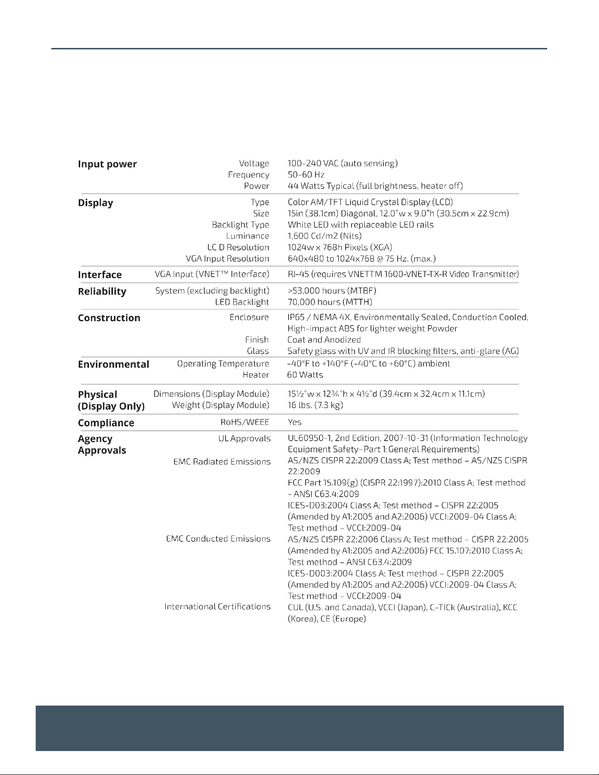
3.1 Front of Display
The front of the display is shown in the figure below. The light sensor and power indicator display is located
in the lower left hand corner of the display. The serial number is located on the front edge of the upper left
corner of the LCD behind the black bezel.
Unit Serial Number (also on rear label)
3.2 Rear of Display
Video Input
(RJ45)
Connector)
120VAC Power
Input
Light Sensor / Status Indicator Board
Figure 1 – Front of Display
Diagnostic Connector –
NOT USED
External Fan Conector -
OPTIONAL
120VAC Power
Indicator Light
Figure 2 – Rear of Display
Document: RDS-INS9293V, Rev. C
Printed copies are Uncontrolled unless clearly marked as a Controlled document. User is responsible for verifying document is the current revision.
Do not copy or distribute without written permission. Unpublished Work 2019 Delphi Display Systems, Inc. All rights reserved.
Page 5

Model 9320-150 Installation Instructions Page 5 of 13
4 System Connections
The Endura 15V model 9320-150 V-net order confirmation display and transmitter are connected using the
supplied CAT5 cable as shown in the figures below. The V-Net video transmitter is connected to the external
PC or video server using the supplier VGA video cable as shown in the figure below.
Figure 3 – System Connections
4.1 Supplied Equipment
The following components are supplied with the Endura® 15V Model 9320 V-Net Display Module. Please
note that the components may vary based on the destination market and specific customer requirements.
Item Description Part Number Optional Part Number
Endura 15V Display Module 9320-150-VC5-RP
Video Transmitter Kit 1601-VNET-TX-RI (International,
without Power Supply)
CAT5 Cable Kit 3232-200-CAT5 (White CAT5
Cable, 200 ft., RJ45 Field
Connector
Document: RDS-INS9293V, Rev. C
Do not copy or distribute without written permission. Unpublished Work 2019 Delphi Display Systems, Inc. All rights reserved.
Printed copies are Uncontrolled unless clearly marked as a Controlled document. User is responsible for verifying document is the current revision.
1601-VNET-TX-R (Domestic US
with Power Supply)
DCN1546440-1 (RJ45 Field
Connector only)
Page 6

Model 9320-150 Installation Instructions Page 6 of 13
4.2 Display Mounting Options
The Model 9320 V-Net Display Module can be mounted using a variety of different mounting enclosures.
Depending on the type of mounting option (canopy, speaker stand, menu board, etc.), Delphi may either
supply part or all of the necessary equipment. Please refer to the appropriate manual for the different
mounting options.
5 Installation Procedures
5.1 Display Installation
Install the 9320 V-Net Display Module into the applicable mounting option utilizing the supplied mounting
instructions. Once the Display is installed, pull the supplied CAT5E cable from the display to the location of
the external PC or video server.
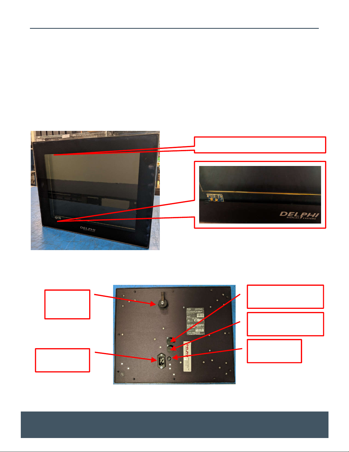
5.2 CAT5 Cable Termination at the Display
The CAT5E cable should be terminated and connected to the back of the display using the supplied
waterproof RJ45 Field Connector Kit as seen in the figure below. Note: Failure to use the supplied
waterproof connector will void the system warranty!
Figure 4 - Detail of Watertight Field Connector Kit
Very Important
The Field Connector Kit contains a SHIELDED RJ45 connector as shown on the right below. This connector
MUST be used on the back of the display. Use of any other type of connector on the back of the display will
result in a loose connection, and will void the customer’s warranty. Although the shielded connector is
necessary, it is not actually used as a shield, so shield wires will not be connected to it.
Document: RDS-INS9293V, Rev. C
Printed copies are Uncontrolled unless clearly marked as a Controlled document. User is responsible for verifying document is the current revision.
Do not copy or distribute without written permission. Unpublished Work 2019 Delphi Display Systems, Inc. All rights reserved.
Page 7

Model 9320-150 Installation Instructions Page 7 of 13
Figure 5 - Detail of Non-Shielded vs. Shielded RJ45 Connector
Document: RDS-INS9293V, Rev. C
Printed copies are Uncontrolled unless clearly marked as a Controlled document. User is responsible for verifying document is the current revision.
Do not copy or distribute without written permission. Unpublished Work 2019 Delphi Display Systems, Inc. All rights reserved.
Page 8

Model 9320-150 Installation Instructions Page 8 of 13
Terminate the CAT5E cable using the standard 568B wiring pin-out as shown in the figure below.
Figure 6 - Standard 568B Pinout Detail
To begin the process of assembling the Field Connector kit for connection to the back of the display; First,
place the small compression nut, the grommet, the large compression nut, the o-ring and the housing on
the cable as seen in the figure below.
Figure 7 – Field Connector Assembly Step 1
Next, strip the jacket from the end of the CAT5E cable, and put the parts together loosely (do not tighten) as
shown below.
Document: RDS-INS9293V, Rev. C
Printed copies are Uncontrolled unless clearly marked as a Controlled document. User is responsible for verifying document is the current revision.
Do not copy or distribute without written permission. Unpublished Work 2019 Delphi Display Systems, Inc. All rights reserved.
Page 9

Model 9320-150 Installation Instructions Page 9 of 13
Figure 8 - Field Connector Assembly Step 2
Next, untwist the wires and place them into the correct order for 568B termination. Cut the length of the
wires down to approx ½ ” (13mm), then terminate the cable with the supplied shielded RJ45 connector as
shown below.
Figure 9 - Field Connector Assembly Step 3
Slide the housing up the cable until the RJ45 connector is seated into the housing. Place one of the two
supplied retainer clips (the other one is a spare) into the slot and ensure it is clipped into place as shown
below.
Figure 10 - Field Connector Assembly Step 4
Document: RDS-INS9293V, Rev. C
Printed copies are Uncontrolled unless clearly marked as a Controlled document. User is responsible for verifying document is the current revision.
Do not copy or distribute without written permission. Unpublished Work 2019 Delphi Display Systems, Inc. All rights reserved.
Page 10
Model 9320-150 Installation Instructions Page 10 of 13
Lastly, tighten the compression nut and the assembly is complete. The completed connector should look
like the one pictured below.
Figure 11 - Field Connector Assembly Step 5
The water-proof RJ45 connector is now ready for connection to the display. Plug the connector to the back
of the display at the RJ45 receptacle. Once connected, screw the “Connector Nut” into the back of the
display until it is tight. Refer to the figure below for an example of a proper connection.
Figure 12 – Connecting the RJ45 connector to the Display
5.3 V-Net Transmitter Installation
Route the CAT5 cable from where the display is mounted to the area where the video server or PC that will
be providing the VGA signal is located. The V-Net transmitter should be installed close to the video server,
preferably permanently mounted using provided mounting screws to minimize movement of the
transmitter device and potential damage to the attached cables. The transmitter should be within 3ft. or 1
meter of the video server and an available wall outlet (to supply power to the Transmitter). Terminate the
end of the Cat5e cable with a standard RJ45 connector wired exactly the same way as the other end was
done. Note: the power supply MUST be attached to the transmitter to insure functionality. Though some
Document: RDS-INS9293V, Rev. C
Printed copies are Uncontrolled unless clearly marked as a Controlled document. User is responsible for verifying document is the current revision.
Do not copy or distribute without written permission. Unpublished Work 2019 Delphi Display Systems, Inc. All rights reserved.
Page 11

Model 9320-150 Installation Instructions Page 11 of 13
lights may be visible on the transmitter without the power supply connected, failure to use the power
supply may prevent functionality. Always use the power supply.
5.3.1 V-Net Transmitter Detail
VGA ACTIVE lit when VGA
signal present in VGA IN
connector
RS232 Diagnostic
Connector. NOT
USED.
USB Diagnostic
Connector. NOT
USED.
Power Indicator
Video output signal
connected via CAT5
cable to the display
Aux VGA Onput
Connector can be
connected to a
local VGA monitor
to view the video
being transmitted
to the VNet display
VGA Input
Connector to be
connected to the
VGA output of the
video server
+12VDC Power
Input to be
connected external
power supply
transformer
Figure 13 – V-Net Transmitter Detail
5.4 Connecting Power to the Display
Connect the 120VAC power cable to the power input connector on the rear panel of the display as shown
below. Verify that the power indicator lights up.
***WARNING***
Do not apply power to
the display until both
ends of the CAT5 cable
have been terminated
and connected.
Verify that the
power indicator
light is on when
power is applied
Figure 14 – Display Power Connection
Document: RDS-INS9293V, Rev. C
Printed copies are Uncontrolled unless clearly marked as a Controlled document. User is responsible for verifying document is the current revision.
Do not copy or distribute without written permission. Unpublished Work 2019 Delphi Display Systems, Inc. All rights reserved.
Page 12

Model 9320-150 Installation Instructions Page 12 of 13
6 System Test
Apply power to the V-Net display and the V-Net Transmitter.
6.1 V-Net Transmitter Test
Verify that the V-Net transmitter has power and that there is an active VGA video signal on the VGA IN video
input. Both indicator lights should be illuminated as shown below.
Verify that VGA
Active indicator is
illuminated
If there is no active VGA video signal on the VGA IN video input, the VGA ACTIVE light will not be illuminated.
In this case, check the video connection to the video server. An eternal VGA monitor can be connected to
the AUX VGA OUT connector to verify video is present on the VGA IN connector.
6.2 V-Net Display Test
With the active VGA signal connected to the transmitter, verify that the V-Net Display is showing the video
image correctly on the screen. If the image is visible but distorted, make sure that the VGA resolution is set
for 1024x768 pixels resolution (XGA). Verify that the green indicator light on the front of the display is
flashing at approximately once every two seconds, indicating that the display is receiving video over the
CAT5 cable from the V-Net transmitter.
Verify that green
front indicator is
flashing once every
2 seconds
If no video is being transmitted to the display, the screen will immediately show a “No Video” error message,
after which the “No Video” message will disappear and blank screen (typically white) will display indicating
that the display is awaiting a valid video input. If this is the case, please check all connections and re-test.
Document: RDS-INS9293V, Rev. C
Printed copies are Uncontrolled unless clearly marked as a Controlled document. User is responsible for verifying document is the current revision.
Do not copy or distribute without written permission. Unpublished Work 2019 Delphi Display Systems, Inc. All rights reserved.
Page 13

Model 9320-150 Installation Instructions Page 13 of 13
7 Technical Support
For technical assistance, please contact:
Delphi Display Systems, Inc.
3550 Hyland Avenue
Costa Mesa, CA 92626
In the US : 1-800-456-0060
1. Select menu Option 1 for technical support
2. Select Option 2 for timer support
International : +1-714-825-3400
Email: techsupport@delphidisplay.com
8 Document Revisions
Revision # Date Notes
C 5/13/19 Major rewrite and reformat.
Document: RDS-INS9293V, Rev. C
Printed copies are Uncontrolled unless clearly marked as a Controlled document. User is responsible for verifying document is the current revision.
Do not copy or distribute without written permission. Unpublished Work 2019 Delphi Display Systems, Inc. All rights reserved.
 Loading...