

Page 1
WORKSHOP MANUAL
)
DP200 SERIES FUEL INJECTION PUMP
2008
DDNX121A(EN)DDNX121A(EN
Page 2
(
D)
Kommen Sie nicht mit dem Hochdruckstrahl in Verbindung! Besonders nicht, wenn
Druckrohrleitung oder Dichtung geprüft werden! Hochdruckflüssigkeiten können tödliche
Verletzungen verursachen! Im Falle einer Berührung mit der Haut, kontaktieren Sie
sofort einen Arzt. Bitte beachten Sie die Gesundheits-/und Sicherheitsunterlagen.
(E)
Mantenga las manos y el cuerpo lejos del rociado del líquido, especialmente inyectores,
tuberías y juntas de alta presión con fugas. La inyección de alta presión puede perforar
la piel humana y producir una lesión fatal. En caso de que la inyección atraviese la piel,
consiga atención médica inmediatamente. Vea la hoja de Datos de Sanidad y
Seguridad.
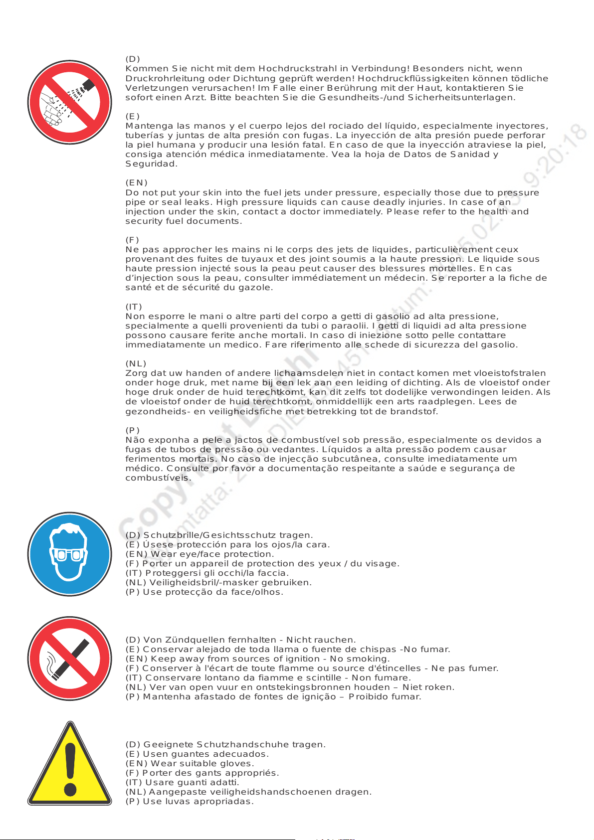
(EN)
Do not put your skin into the fuel jets under pressure, especially those due to pressure
pipe or seal leaks. High pressure liquids can cause deadly injuries. In case of an
injection under the skin, contact a doctor immediately. Please refer to the health and
security fuel documents.
(F)
Ne pas approcher les mains ni le corps des jets de liquides, particulièrement ceux
provenant des fuites de tuyaux et des joint soumis a la haute pression. Le liquide sous
haute pression injecté sous la peau peut causer des blessures mortelles. En cas
d’injection sous la peau, consulter immédiatement un médecin. Se reporter a la fiche de
santé et de sécurité du gazole.
(IT)
Non esporre le mani o altre parti del corpo a getti di gasolio ad alta pressione,
specialmente a quelli provenienti da tubi o paraolii. I getti di liquidi ad alta pressione
possono causare ferite anche mortali. In caso di iniezione sotto pelle contattare
immediatamente un medico. Fare riferimento alle schede di sicurezza del gasolio.
(NL)
Zorg dat uw handen of andere lichaamsdelen niet in contact komen met vloeistofstralen
onder hoge druk, met name bij een lek aan een leiding of dichting. Als de vloeistof onder
hoge druk onder de huid terechtkomt, kan dit zelfs tot dodelijke verwondingen leiden. Als
de vloeistof onder de huid terechtkomt, onmiddellijk een arts raadplegen. Lees de
gezondheids- en veiligheidsfiche met betrekking tot de brandstof.
(P)
Não exponha a pele a jactos de combustível sob pressão, especialmente os devidos a
fugas de tubos de pressão ou vedantes. Líquidos a alta pressão podem causar
ferimentos mortais. No caso de injecção subcutânea, consulte imediatamente um
médico. Consulte por favor a documentação respeitante a saúde e segurança de
combustíveis.
(D) Schutzbrille/Gesichtsschutz tragen.
(E) Úsese protección para los ojos/la cara.
(EN) Wear eye/face protection.
(F) Porter un appareil de protection des yeux / du visage.
(IT) Proteggersi gli occhi/la faccia.
(NL) Veiligheidsbril/-masker gebruiken.
(P) Use protecção da face/olhos.
(D) Von Zündquellen fernhalten - Nicht rauchen.
(E) Conservar alejado de toda llama o fuente de chispas -No fumar.
(EN) Keep away from sources of ignition - No smoking.
(F) Conserver à l'écart de toute flamme ou source d'étincelles - Ne pas fumer.
(IT) Conservare lontano da fiamme e scintille - Non fumare.
(NL) Ver van open vuur en ontstekingsbronnen houden – Niet roken.
(P) Mantenha afastado de fontes de ignição – Proibido fumar.
(D) Geeignete Schutzhandschuhe tragen.
(E) Usen guantes adecuados.
(EN) Wear suitable gloves.
(F) Porter des gants appropriés.
(IT) Usare guanti adatti.
(NL) Aangepaste veiligheidshandschoenen dragen.
(P) Use luvas apropriadas.
Page 3
TABLE OF CONTENTS
INTRODUCTION I
DISMANTLING II
COMPONENT INSPECTION AND RENEWAL III
REASSEMBLY IV
TEST PROCEDURE V
© Delphi
DDNX121A(EN) - Issue 1 of 08/2008
i
Page 4
TABLE OF CONTENTS
TOOLING, TORQUES & EVDS VI
APPENDIX VII
Produced and published by:
Delphi Diesel Systems Ltd.
Spartan Close
Warwick CV34 6AG Tel: +44 (0) 1926 472 900
England Fax: +44 (0) 1926 472 901
ii
© Delphi
DDNX121A(EN) - Issue 1 of 08/2008
Page 5
INTRODUCTION I
TABLE OF CONTENTS
1.
INTRODUCTION
1.1 The Pump.......................................................................................................................................................................1-1
1.2 General...........................................................................................................................................................................1-1
1.3 This Manual...................................................................................................................................................................1-2
1.4 Equipment......................................................................................................................................................................1-2
1.5 Replacement Of Parts...................................................................................................................................................1-2
1.6 Pump Name Plate..........................................................................................................................................................1-3
© Delphi
DDNX121A(EN) - Issue 1 of 08/2008
iii
Page 6
II DISMANTLING
TABLE OF CONTENTS
2.
DISMANTLING
2.1 Preparation....................................................................................................................................................................2-5
2.1.1 Cleaning and draining..................................................................................................................................2-5
2.1.2 Mounting the pump.....................................................................................................................................2-5
2.1.3 Removing sealing caps and locking wire...................................................................................................2-5
2.1.4 Removing the drive hub (if fitted)...............................................................................................................2-6
2.1.5 Measuring drive shaft end float..................................................................................................................2-6
2.1.6 Measuring drive shaft radial play...............................................................................................................2-7
2.2 Governor Cover, Control Levers & Link Assembly.....................................................................................................2-7
2.2.1 Removing the fuel return connections.......................................................................................................2-7
2.2.2 Removing the throttle lever stop screws, maximum fuel screw, and torque control screw.................2-8
2.2.3 Removing the throttle lever.........................................................................................................................2-8
2.2.4 Removing the exhaust brake lever.............................................................................................................2-9
2.2.5 Removing the electronic actuator throttle lever (rigid type)....................................................................2-9
2.2.6 Removing the governor cover assembly.................................................................................................2-10
2.3 Dismantling The All-Speed Govenor.........................................................................................................................2-16
2.4 Removing The Control Bracket And Arm Assembly................................................................................................2-17
2.4.1 Removing the scroll link plate return spring............................................................................................2-17
2.4.2 Removing the governor control bracket assembly.................................................................................2-17
2.4.3 Dismantling the governor control arm assembly....................................................................................2-18
2.4.4 Dismantling the governor control plate assembly for torque trimmer variant....................................2-18
2.5 High Pressure Outlets Assembly, Electric Shut-off Solenoid (ESOS) & Transfer Pump.......................................2-19
2.5.1 High pressure outlets.................................................................................................................................2-19
2.5.2 Endplate assembly.....................................................................................................................................2-19
2.6 Electric Shut-off Solenoid (ESOS)..............................................................................................................................2-21
2.7 Transfer Pump.............................................................................................................................................................2-21
2.7.1 Removing the transfer pump components..............................................................................................2-21
2.7.2 Slackening the transfer pump rotor..........................................................................................................2-21
2.8 Advance Device...........................................................................................................................................................2-22
2.8.1 Single piston design with 2 bolt cold advance (CA)................................................................................2-22
2.8.2 Servo piston design with 2 bolt Cold Advance........................................................................................2-23
2.8.3 Servo piston design with 4 bolt cold advance.........................................................................................2-26
2.8.4 Single piston design without cold advance.............................................................................................2-27
2.9 Removing The Head Locking Screws And Releasing The Hydraulic Head............................................................2-28
2.9.1 Head locking screws..................................................................................................................................2-28
2.9.2 Removing and dismantling the LLA.........................................................................................................2-28
2.9.3 Removing and dismantling the latch valve..............................................................................................2-29
2.9.4 Removing the hydraulic head...................................................................................................................2-29
2.10 Drive Shaft...................................................................................................................................................................2-30
2.10.1 Dismantling the Zero Backlash Drive assembly......................................................................................2-30
2.10.2 Dismantling the splined drive assembly..................................................................................................2-32
2.11 Dismantling The Hydraulic Head - Check And Cheek Plate Designs......................................................................2-33
2.11.1 Releasing the drive plate screws..............................................................................................................2-33
2.11.2 Dismantling the rotor components...........................................................................................................2-33
2.11.3 Removing the lower check or cheek plate...............................................................................................2-33
2.11.4 Reverse thrust weight assembly...............................................................................................................2-34
2.11.5 Lock-shaft timing........................................................................................................................................2-34
iv
© Delphi
DDNX121A(EN) - Issue 1 of 08/2008
Page 7
DISMANTLING II
TABLE OF CONTENTS
2.11.6 Removing the drive shaft seal/s................................................................................................................2-35
© Delphi
DDNX121A(EN) - Issue 1 of 08/2008
v
Page 8
III COMPONENT INSPECTION AND RENEWAL
TABLE OF CONTENTS
3.
COMPONENT INSPECTION AND RENEWAL
3.1 Cleaning.......................................................................................................................................................................3-37
3.2 GeneraL........................................................................................................................................................................3-37
3.2.1 Mated and matched assemblies...............................................................................................................3-37
3.2.2 Examination and replacement..................................................................................................................3-37
3.2.3 Seals............................................................................................................................................................3-38
3.3 Details...........................................................................................................................................................................3-38
3.3.1 Hydraulic head rotor..................................................................................................................................3-38
3.3.2 Hydraulic head plungers............................................................................................................................3-38
3.3.3 Cam ring and scroll plates.........................................................................................................................3-38
3.3.4 Rollers and shoes.......................................................................................................................................3-38
3.3.5 Transfer pump............................................................................................................................................3-38
3.3.6 Endplate......................................................................................................................................................3-39
3.3.7 Control valves.............................................................................................................................................3-39
3.3.8 Delivery valves and cambox pressurising valves....................................................................................3-39
3.3.9 High pressure outlet pressurising valves.................................................................................................3-39
3.3.10 Springs........................................................................................................................................................3-39
3.3.11 Fittings and threads...................................................................................................................................3-39
3.3.12 Linkages......................................................................................................................................................3-39
3.3.13 Control shafts.............................................................................................................................................3-39
3.3.14 Drive shafts and associated components................................................................................................3-39
3.3.15 Advance device..........................................................................................................................................3-40
3.3.16 Levers and external controls.....................................................................................................................3-40
3.3.17 Pump housing............................................................................................................................................3-40
3.3.18 Governor control cover..............................................................................................................................3-40
3.3.19 Orifices........................................................................................................................................................3-40
3.3.20 Electric shut-off solenoid...........................................................................................................................3-40
3.3.21 Wax motor..................................................................................................................................................3-40
vi
© Delphi
DDNX121A(EN) - Issue 1 of 08/2008
Page 9
REASSEMBLY IV
TABLE OF CONTENTS
4.
REASSEMBLY
4.1 Preparation..................................................................................................................................................................4-43
4.2 Assembling The Hydraulic Head................................................................................................................................4-43
4.2.1 Rotor plug...................................................................................................................................................4-43
4.2.2 Drive plate, rollers, shoes and retaining plates.......................................................................................4-44
4.3 Drive Shaft...................................................................................................................................................................4-47
4.3.1 Zero backlash and splined drive with cheek plates.................................................................................4-47
4.3.2 Spline drive with check plate head and rotor..........................................................................................4-50
4.4 Securing The Hydraulic Head And Checking Drive Shaft End Float And Radial Play...........................................4-51
4.4.1 Replacing the drive shaft seal/s................................................................................................................4-51
4.4.2 Securing the drive shaft.............................................................................................................................4-52
4.4.3 Aligning the hydraulic head......................................................................................................................4-52
4.4.4 Checking drive shaft end float...................................................................................................................4-52
4.4.5 Checking drive shaft radial play................................................................................................................4-53
4.4.6 Cam advance screw...................................................................................................................................4-53
4.4.7 Fitting the head locking screws, light load advance valve and latch valves.........................................4-54
4.5 Advance Device...........................................................................................................................................................4-55
4.5.1 Single piston design..................................................................................................................................4-56
4.5.2 Servo piston designs.................................................................................................................................4-58
4.5.3 2 Bolt Cold Advance fitted to single piston design.................................................................................4-62
4.5.4 4 Bolt Cold Advance fitted to servo piston design..................................................................................4-64
4.6 Transfer Pump And Endplate Assembly...................................................................................................................4-64
4.6.1 Transfer pump............................................................................................................................................4-64
4.6.2 Endplate assembly.....................................................................................................................................4-65
4.7 ESOS And High Pressure Outlets..............................................................................................................................4-68
4.7.1 ESOS or blanking plug...............................................................................................................................4-68
4.7.2 High pressure outlets and clamp plate.....................................................................................................4-68
4.8 Governor Linkage, Control Bracket And Cover.........................................................................................................4-69
4.8.1 Governor linkage........................................................................................................................................4-69
4.8.2 Fitting the governor assembly to the pump............................................................................................4-70
4.8.3 Fitting the scroll link plate return spring..................................................................................................4-70
4.8.4 Setting the governor link length...............................................................................................................4-71
4.8.5 Fitting the governor assembly for torque trimmer variant.....................................................................4-71
4.9 Assembling The Governor Cover..............................................................................................................................4-74
4.9.1 Governor cover only..................................................................................................................................4-74
4.9.2 Governor cover fitted with hydraulic excess fuel....................................................................................4-75
4.9.3 Governor cover fitted with boost control only........................................................................................4-77
4.9.4 Governor covers fitted with torque control and torque control plus boost control.............................4-81
4.9.5 Governor covers fitted with electronic actuator......................................................................................4-86
4.10 Governor Cover External Components.....................................................................................................................4-89
4.10.1 Fitting backleak connections.....................................................................................................................4-89
4.10.2 Fitting and aligning external levers..........................................................................................................4-89
4.10.3 Control stop screws and plugs..................................................................................................................4-90
4.11 Shaft Locking Screw Cover And Cam Ring Access Plug.........................................................................................4-92
4.11.1 Shaft locking screw....................................................................................................................................4-92
4.11.2 Drain plug...................................................................................................................................................4-92
4.11.3 Cover...........................................................................................................................................................4-92
© Delphi
DDNX121A(EN) - Issue 1 of 08/2008
vii
Page 10
IV REASSEMBLY
TABLE OF CONTENTS
4.11.4 Cam ring access plug.................................................................................................................................4-92
4.12 Drive Hub.....................................................................................................................................................................4-93
4.13 Leak Testing.................................................................................................................................................................4-93
4.14 Storage.........................................................................................................................................................................4-93
4.14.1 New pumps.................................................................................................................................................4-93
4.14.2 Overhauled pumps.....................................................................................................................................4-93
4.14.3 Storage conditions.....................................................................................................................................4-93
viii
© Delphi
DDNX121A(EN) - Issue 1 of 08/2008
Page 11
TEST PROCEDURE V
TABLE OF CONTENTS
5.
TEST PROCEDURE
5.1 Preparation..................................................................................................................................................................5-95
5.1.1 Leak testing.................................................................................................................................................5-95
5.1.2 Test machine..............................................................................................................................................5-95
5.1.3 Test machine drive.....................................................................................................................................5-95
5.1.4 Test conditions...........................................................................................................................................5-96
5.1.5 Connecting fuel lines.................................................................................................................................5-97
5.1.6 Machine test procedure.............................................................................................................................5-97
5.1.7 Transfer pressure measurement and initial setting................................................................................5-98
5.1.8 Cambox pressure measurement...............................................................................................................5-99
5.1.9 Adjustments to be pre-set.........................................................................................................................5-99
5.2 Test Procedure...........................................................................................................................................................5-101
5.2.1 Priming......................................................................................................................................................5-101
5.2.2 Checking and setting transfer pressure..................................................................................................5-102
5.2.3 Cambox pressure and backleakage checks............................................................................................5-103
5.2.4 Speed advance setting.............................................................................................................................5-103
5.2.5 Cold advance............................................................................................................................................5-104
5.2.6 Light-load advance valve setting............................................................................................................5-104
5.2.7 Boost control with torque trimmer.........................................................................................................5-105
5.2.8 Maximum fuel delivery setting...............................................................................................................5-106
5.2.9 Latch valve................................................................................................................................................5-107
5.2.10 Governor setting and testing..................................................................................................................5-107
5.2.11 Torque screw setting...............................................................................................................................5-108
5.2.12 Idle setting................................................................................................................................................5-108
5.2.13 Shut-off control check..............................................................................................................................5-109
5.3 Timing........................................................................................................................................................................5-109
5.3.1 General......................................................................................................................................................5-109
5.3.2 Keyed drive shafts....................................................................................................................................5-110
5.3.3 Keyless drive shafts.................................................................................................................................5-111
5.4 Leakage Testing.........................................................................................................................................................5-114
© Delphi
DDNX121A(EN) - Issue 1 of 08/2008
ix
Page 12
VI TOOLING, TORQUES & EVDS
TABLE OF CONTENTS
6.
TOOLING, TORQUES & EVDS
6.1 Tooling.......................................................................................................................................................................6-115
6.2 Torque Values............................................................................................................................................................6-118
6.3 Exploded View Diagram...........................................................................................................................................6-125
© Delphi
x
DDNX121A(EN) - Issue 1 of 08/2008
Page 13
APPENDIX VII
TABLE OF CONTENTS
7.
APPENDIX
7.1 Abbreviations Used In This Manual........................................................................................................................7-137
© Delphi
DDNX121A(EN) - Issue 1 of 08/2008
xi
Page 14

VII APPENDIX
TABLE OF CONTENTS
xii
© Delphi
DDNX121A(EN) - Issue 1 of 08/2008
Page 15
1.1 The Pump
INTRODUCTION I
INTRODUCTION
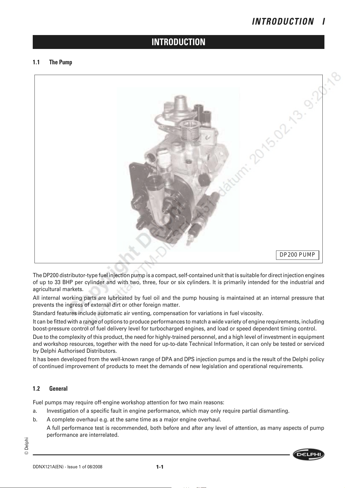
DP200 PUMP
The DP200 distributor-type fuel injection pump is a compact, self-contained unit that is suitable for direct injection engines
of up to 33 BHP per cylinder and with two, three, four or six cylinders. It is primarily intended for the industrial and
agricultural markets.
All internal working parts are lubricated by fuel oil and the pump housing is maintained at an internal pressure that
prevents the ingress of external dirt or other foreign matter.
Standard features include automatic air venting, compensation for variations in fuel viscosity.
It can be fitted with a range of options to produce performances to match a wide variety of engine requirements, including
boost-pressure control of fuel delivery level for turbocharged engines, and load or speed dependent timing control.
Due to the complexity of this product, the need for highly-trained personnel, and a high level of investment in equipment
and workshop resources, together with the need for up-to-date Technical Information, it can only be tested or serviced
by Delphi Authorised Distributors.
It has been developed from the well-known range of DPA and DPS injection pumps and is the result of the Delphi policy
of continued improvement of products to meet the demands of new legislation and operational requirements.
1.2 General
Fuel pumps may require off-engine workshop attention for two main reasons:
a. Investigation of a specific fault in engine performance, which may only require partial dismantling.
b. A complete overhaul e.g. at the same time as a major engine overhaul.
A full performance test is recommended, both before and after any level of attention, as many aspects of pump
performance are interrelated.
© Delphi
DDNX121A(EN) - Issue 1 of 08/2008
1-1
Page 16
I INTRODUCTION
INTRODUCTION
1.3 This Manual
The Dismantling, Reassembly and Testing Sections are laid out on a "step-by-step" basis, with each action accompanied
by an illustration showing the component(s) involved and, where applicable, its/their positions on the pump. The Manual
is not based on any one specification, but covers pump features which have been included up to the time of publication.
For the purposes of illustration, more than one pump specification has been used.
The pumps illustrated are for clockwise rotation (when viewed from the drive end); anticlockwise pumps will have items
such as the maximum fuel screw, and the boost control fitted on the side opposite to that shown. In addition, the advance
device will operate in the opposite mode.
Instructions for both full and partial dismantling of the pump are included e.g. total dismantling and examination of all
components other than those that are factory-sealed units and removal of the hydraulic head and rotor only.
All the necessary tools are listed in Section 6. Special tools are identified by part number and standard tools by type and
size.
1.4 Equipment
Any tools, both standard and special-purpose, used for the servicing or repair of fuel injection equipment (FIE) must be
reserved solely for use on FIE. Worn or damaged tools can cause damage to critical components, as well as being a
safety hazard.
The working area must be scrupulously clean and should be in a room separated from any other activity; the ingress of
dust and dirt, airborne or otherwise, must be prevented.
The minimum facilities required are:
1. A bench covered in non-rusting metal or industrialgrade linoleum and fitted with an engineer's vice with a jaw size
of 100 mm (4 in). The vice jaws must be faced with either soft metal or fibre pads.
2. An adjustable pump-mounting device such as the "Hydraclamp", fitted with an appropriate adaptor plate.
3. Easily cleaned compartmented trays for separate storage of dismantled components such as Part No. 60620197.
4. All the necessary tools as listed in Section 6 of this Manual.
5. A low-pressure washing facility using a suitable, approved, cleaning fluid (not water or water-based) to clean pumps
externally prior to dismantling.
Cleaning must be carried out in a place separated from the "clean area".
6. A tank large enough to accommodate a complete pump and filled with clean test oil, near to a source of clean, dry,
variable pressure compressed air for carrying out leakage tests.
7. Supplies of clean, lint-free (non-fluffy) cloths for cleaning and drying components. Cotton waste must never be
used.
8. A pump test machine that conforms to ISO 4008.
9. Adequate storage facilities for pumps, tools and test equipment, with separate areas for pumps before and after
repair.
Note:
All cleaning tanks, workshop and test facilities and fluids must conform to any Fire Prevention or Health and Safety
Regulations in force at the time of use.
1.5 Replacement Of Parts
All gaskets and seals must be replaced during reassembly. However, in the event of partial dismantling, only those seals
that have been disturbed need replacement, unless leaks from elsewhere are detected during testing prior to dismantling.
If any part of a "mated" assembly is worn or damaged, the whole assembly must be replaced. Any component showing
signs of corrosion or water ingress, cracks or distortion must be replaced.
1-2
DDNX121A(EN) - Issue 1 of 08/2008
© Delphi
Page 17
INTRODUCTION I
INTRODUCTION
Only service parts supplied by Delphi Diesel Systems Aftermarket Operations may be used as replacements. Parts
supplied from alternative sources may appear to be externally similar and may carry the same part numbers as the
genuine item but may be inferior in material specification or finish and lead to malfunction or premature failure.
1.6 Pump Name Plate
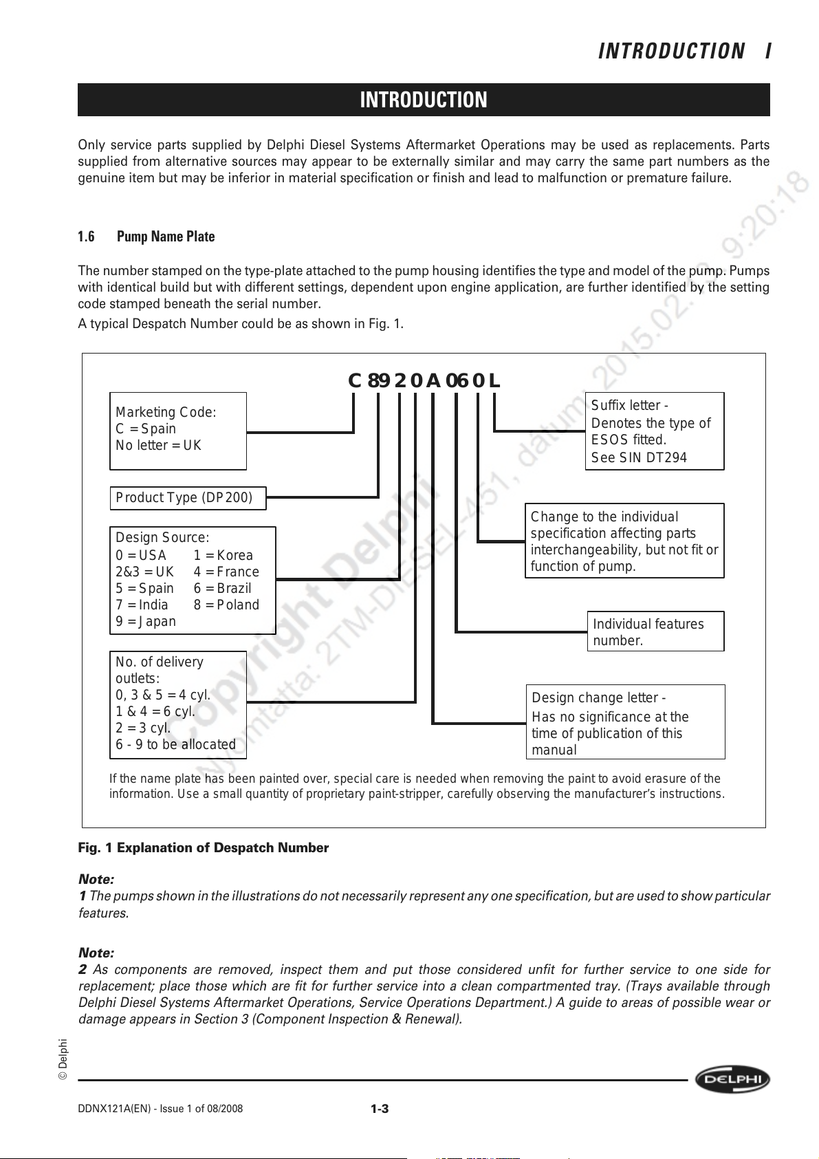
The number stamped on the type-plate attached to the pump housing identifies the type and model of the pump. Pumps
with identical build but with different settings, dependent upon engine application, are further identified by the setting
code stamped beneath the serial number.
A typical Despatch Number could be as shown in Fig. 1.
C 89 2 0 A 06 0 L
Marketing Code:
C = Spain
No letter = UK
Suffix letter -
Denotes the type of
ESOS fitted.
See SIN DT294
Product Type (DP200)
Change to the individual
Design Source:
0 = USA 1 = Korea
2&3 = UK 4 = France
5 = Spain 6 = Brazil
7 = India 8 = Poland
9 = Japan
No. of delivery
outlets:
0, 3 & 5 = 4 cyl.
1 & 4 = 6 cyl.
2 = 3 cyl.
6 - 9 to be allocated
If the name plate has been painted over, special care is needed when removing the paint to avoid erasure of the
information. Use a small quantity of proprietary paint-stripper, carefully observing the manufacturer’s instructions.
Fig. 1 Explanation of Despatch Number
Note:
1 The pumps shown in the illustrations do not necessarily represent any one specification, but are used to show particular
features.
specification affecting parts
interchangeability, but not fit or
function of pump.
Individual features
number.
Design change letter -
Has no significance at the
time of publication of this
manual
Note:
2 As components are removed, inspect them and put those considered unfit for further service to one side for
replacement; place those which are fit for further service into a clean compartmented tray. (Trays available through
Delphi Diesel Systems Aftermarket Operations, Service Operations Department.) A guide to areas of possible wear or
damage appears in Section 3 (Component Inspection & Renewal).
© Delphi
DDNX121A(EN) - Issue 1 of 08/2008
1-3
Page 18

I INTRODUCTION
INTRODUCTION
1-4
© Delphi
DDNX121A(EN) - Issue 1 of 08/2008
Page 19
DISMANTLING
2.1 Preparation
A list of all tools required to dismantle and reassemble the pump is in Section 6.
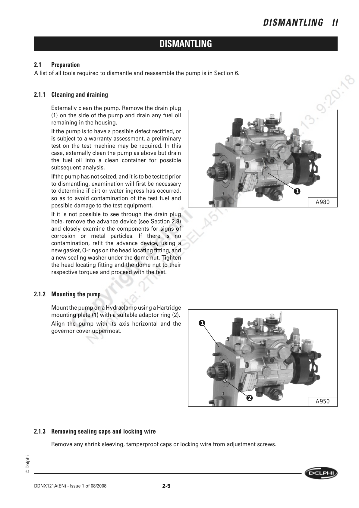
2.1.1 Cleaning and draining
Externally clean the pump. Remove the drain plug
(1) on the side of the pump and drain any fuel oil
remaining in the housing.
If the pump is to have a possible defect rectified, or
is subject to a warranty assessment, a preliminary
test on the test machine may be required. In this
case, externally clean the pump as above but drain
the fuel oil into a clean container for possible
subsequent analysis.
If the pump has not seized, and it is to be tested prior
to dismantling, examination will first be necessary
to determine if dirt or water ingress has occurred,
so as to avoid contamination of the test fuel and
possible damage to the test equipment.
If it is not possible to see through the drain plug
hole, remove the advance device (see Section 2.8)
and closely examine the components for signs of
corrosion or metal particles. If there is no
contamination, refit the advance device, using a
new gasket, O-rings on the head locating fitting, and
a new sealing washer under the dome nut. Tighten
the head locating fitting and the dome nut to their
respective torques and proceed with the test.
DISMANTLING II
1
A980
2.1.2 Mounting the pump
Mount the pump on a Hydraclamp using a Hartridge
mounting plate (1) with a suitable adaptor ring (2).
Align the pump with its axis horizontal and the
governor cover uppermost.
1
2.1.3 Removing sealing caps and locking wire
Remove any shrink sleeving, tamperproof caps or locking wire from adjustment screws.
2
A950
© Delphi
DDNX121A(EN) - Issue 1 of 08/2008
2-5
Page 20
II DISMANTLING
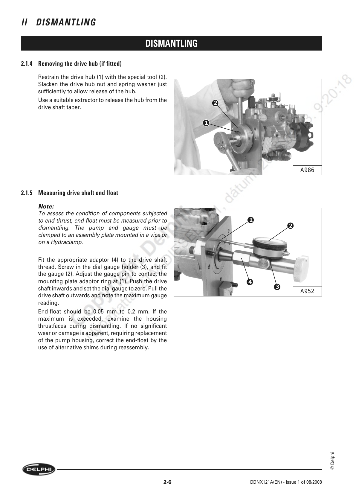
2.1.4 Removing the drive hub (if fitted)
Restrain the drive hub (1) with the special tool (2).
Slacken the drive hub nut and spring washer just
sufficiently to allow release of the hub.
Use a suitable extractor to release the hub from the
drive shaft taper.
2.1.5 Measuring drive shaft end float
DISMANTLING
2
1
A986
Note:
To assess the condition of components subjected
to end-thrust, end-float must be measured prior to
dismantling. The pump and gauge must be
clamped to an assembly plate mounted in a vice or
on a Hydraclamp.
Fit the appropriate adaptor (4) to the drive shaft
thread. Screw in the dial gauge holder (3), and fit
the gauge (2). Adjust the gauge pin to contact the
mounting plate adaptor ring at (1). Push the drive
shaft inwards and set the dial gauge to zero. Pull the
drive shaft outwards and note the maximum gauge
reading.
End-float should be 0.05 mm to 0.2 mm. If the
maximum is exceeded, examine the housing
thrustfaces during dismantling. If no significant
wear or damage is apparent, requiring replacement
of the pump housing, correct the end-float by the
use of alternative shims during reassembly.
1
4
2
3
A952
2-6
© Delphi
DDNX121A(EN) - Issue 1 of 08/2008
Page 21
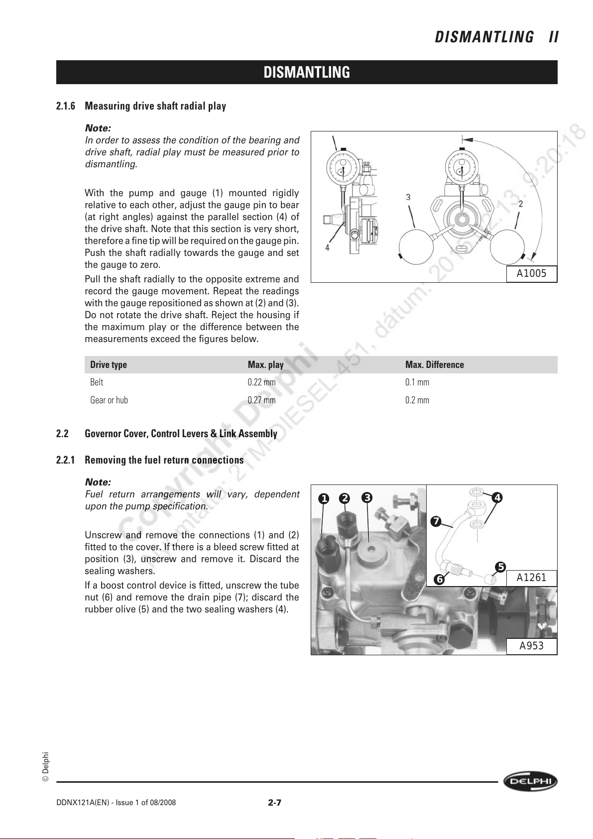
2.1.6 Measuring drive shaft radial play
Note:
In order to assess the condition of the bearing and
drive shaft, radial play must be measured prior to
dismantling.
With the pump and gauge (1) mounted rigidly
relative to each other, adjust the gauge pin to bear
(at right angles) against the parallel section (4) of
the drive shaft. Note that this section is very short,
therefore a fine tip will be required on the gauge pin.
Push the shaft radially towards the gauge and set
the gauge to zero.
Pull the shaft radially to the opposite extreme and
record the gauge movement. Repeat the readings
with the gauge repositioned as shown at (2) and (3).
Do not rotate the drive shaft. Reject the housing if
the maximum play or the difference between the
measurements exceed the figures below.
DISMANTLING II
DISMANTLING
A1005
Drive type Max. play Max. Difference
Belt 0.22 mm 0.1 mm
Gear or hub 0.27 mm 0.2 mm
2.2 Governor Cover, Control Levers & Link Assembly
2.2.1 Removing the fuel return connections
Note:
Fuel return arrangements will vary, dependent
upon the pump specification.
Unscrew and remove the connections (1) and (2)
fitted to the cover. If there is a bleed screw fitted at
position (3), unscrew and remove it. Discard the
sealing washers.
If a boost control device is fitted, unscrew the tube
nut (6) and remove the drain pipe (7); discard the
rubber olive (5) and the two sealing washers (4).
3
2
1
7
6
4
5
A1261
A953
© Delphi
DDNX121A(EN) - Issue 1 of 08/2008
2-7
Page 22
II DISMANTLING
DISMANTLING
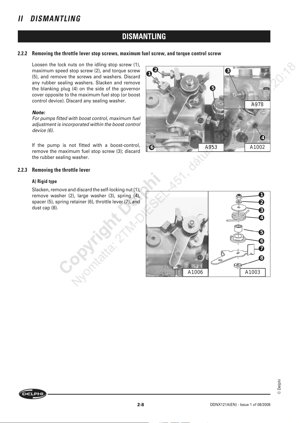
2.2.2 Removing the throttle lever stop screws, maximum fuel screw, and torque control screw
Loosen the lock nuts on the idling stop screw (1),
maximum speed stop screw (2), and torque screw
(5), and remove the screws and washers. Discard
any rubber sealing washers. Slacken and remove
the blanking plug (4) on the side of the governor
cover opposite to the maximum fuel stop (or boost
control device). Discard any sealing washer.
Note:
For pumps fitted with boost control, maximum fuel
adjustment is incorporated within the boost control
device (6).
If the pump is not fitted with a boost-control,
remove the maximum fuel stop screw (3); discard
the rubber sealing washer.
2.2.3 Removing the throttle lever
A) Rigid type
Slacken, remove and discard the self-locking nut (1);
remove washer (2), large washer (3), spring (4),
spacer (5), spring retainer (6), throttle lever (7), and
dust cap (8).
2
1
5
3
A978
4
6
A1002A953
1
2
3
4
A1006 A1003
5
6
7
8
2-8
© Delphi
DDNX121A(EN) - Issue 1 of 08/2008
Page 23
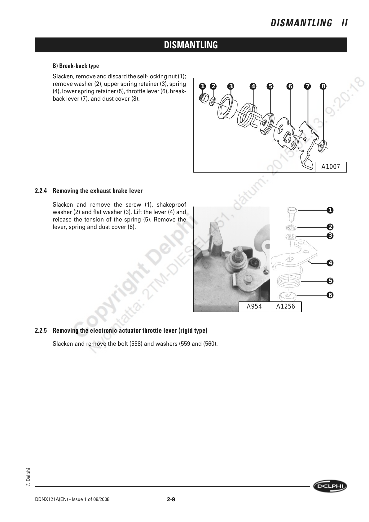
B) Break-back type
Slacken, remove and discard the self-locking nut (1);
remove washer (2), upper spring retainer (3), spring
(4), lower spring retainer (5), throttle lever (6), break-
back lever (7), and dust cover (8).
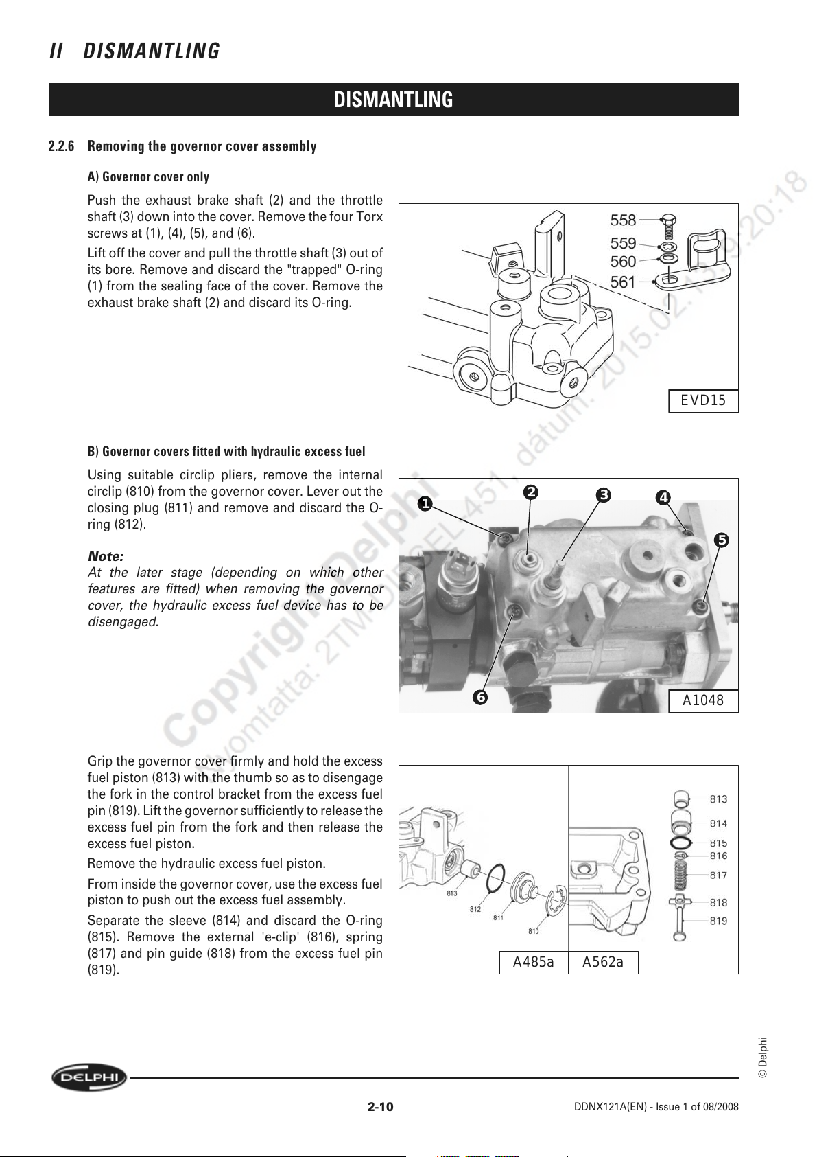
2.2.4 Removing the exhaust brake lever
DISMANTLING II
DISMANTLING
87654321
A1007
Slacken and remove the screw (1), shakeproof
washer (2) and flat washer (3). Lift the lever (4) and
release the tension of the spring (5). Remove the
lever, spring and dust cover (6).
2.2.5 Removing the electronic actuator throttle lever (rigid type)
Slacken and remove the bolt (558) and washers (559 and (560).
1
2
3
4
5
6
A954 A1256
© Delphi
DDNX121A(EN) - Issue 1 of 08/2008
2-9
Page 24
II DISMANTLING
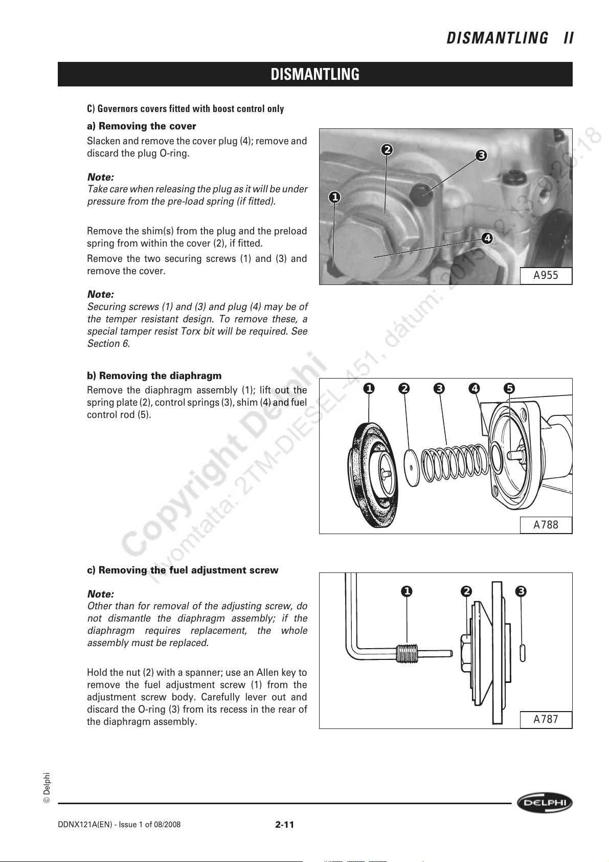
2.2.6 Removing the governor cover assembly
A) Governor cover only
Push the exhaust brake shaft (2) and the throttle
shaft (3) down into the cover. Remove the four Torx
screws at (1), (4), (5), and (6).
Lift off the cover and pull the throttle shaft (3) out of
its bore. Remove and discard the "trapped" O-ring
(1) from the sealing face of the cover. Remove the
exhaust brake shaft (2) and discard its O-ring.
B) Governor covers fitted with hydraulic excess fuel
Using suitable circlip pliers, remove the internal
circlip (810) from the governor cover. Lever out the
closing plug (811) and remove and discard the O-
ring (812).
Note:
At the later stage (depending on which other
features are fitted) when removing the governor
cover, the hydraulic excess fuel device has to be
disengaged.
DISMANTLING
1
EVD15
2
3
4
5
Grip the governor cover firmly and hold the excess
fuel piston (813) with the thumb so as to disengage
the fork in the control bracket from the excess fuel
pin (819). Lift the governor sufficiently to release the
excess fuel pin from the fork and then release the
excess fuel piston.
Remove the hydraulic excess fuel piston.
From inside the governor cover, use the excess fuel
piston to push out the excess fuel assembly.
Separate the sleeve (814) and discard the O-ring
(815). Remove the external 'e-clip' (816), spring
(817) and pin guide (818) from the excess fuel pin
(819).
6
A1048
A562aA485a
© Delphi
2-10
DDNX121A(EN) - Issue 1 of 08/2008
Page 25
DISMANTLING
C) Governors covers fitted with boost control only
a) Removing the cover
Slacken and remove the cover plug (4); remove and
discard the plug O-ring.
Note:
Take care when releasing the plug as it will be under
pressure from the pre-load spring (if fitted).
DISMANTLING II
2
1
3
Remove the shim(s) from the plug and the preload
spring from within the cover (2), if fitted.
Remove the two securing screws (1) and (3) and
remove the cover.
Note:
Securing screws (1) and (3) and plug (4) may be of
the temper resistant design. To remove these, a
special tamper resist Torx bit will be required. See
Section 6.
b) Removing the diaphragm
Remove the diaphragm assembly (1); lift out the
spring plate (2), control springs (3), shim (4) and fuel
control rod (5).
4
A955
1 5432
A788
c) Removing the fuel adjustment screw
Note:
Other than for removal of the adjusting screw, do
not dismantle the diaphragm assembly; if the
diaphragm requires replacement, the whole
assembly must be replaced.
Hold the nut (2) with a spanner; use an Allen key to
remove the fuel adjustment screw (1) from the
adjustment screw body. Carefully lever out and
discard the O-ring (3) from its recess in the rear of
the diaphragm assembly.
© Delphi
DDNX121A(EN) - Issue 1 of 08/2008
1 32
A787
2-11
Page 26
II DISMANTLING
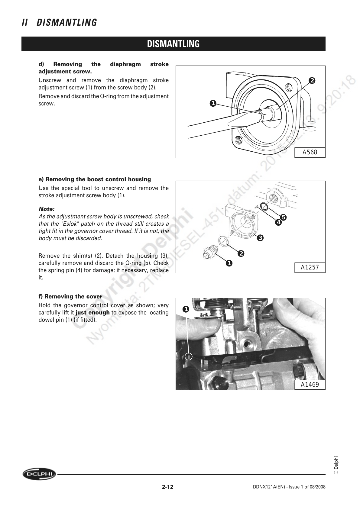
d) Removing the diaphragm stroke
adjustment screw.
Unscrew and remove the diaphragm stroke
adjustment screw (1) from the screw body (2).
Remove and discard the O-ring from the adjustment
screw.
e) Removing the boost control housing
Use the special tool to unscrew and remove the
stroke adjustment screw body (1).
DISMANTLING
2
1
A568
Note:
As the adjustment screw body is unscrewed, check
that the "Eslok" patch on the thread still creates a
tight fit in the governor cover thread. If it is not, the
body must be discarded.
Remove the shim(s) (2). Detach the housing (3);
carefully remove and discard the O-ring (5). Check
the spring pin (4) for damage; if necessary, replace
it.
f) Removing the cover
Hold the governor control cover as shown; very
carefully lift it just enough to expose the locating
dowel pin (1) (if fitted).
5
4
3
2
1
1
A1257
2-12
A1469
© Delphi
DDNX121A(EN) - Issue 1 of 08/2008
Page 27
DISMANTLING
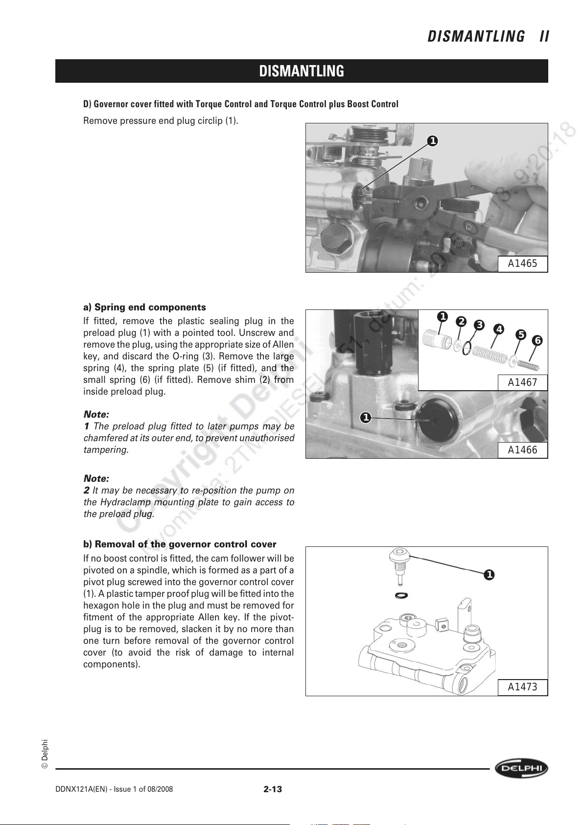
D) Governor cover fitted with Torque Control and Torque Control plus Boost Control
Remove pressure end plug circlip (1).
DISMANTLING II
1
A1465
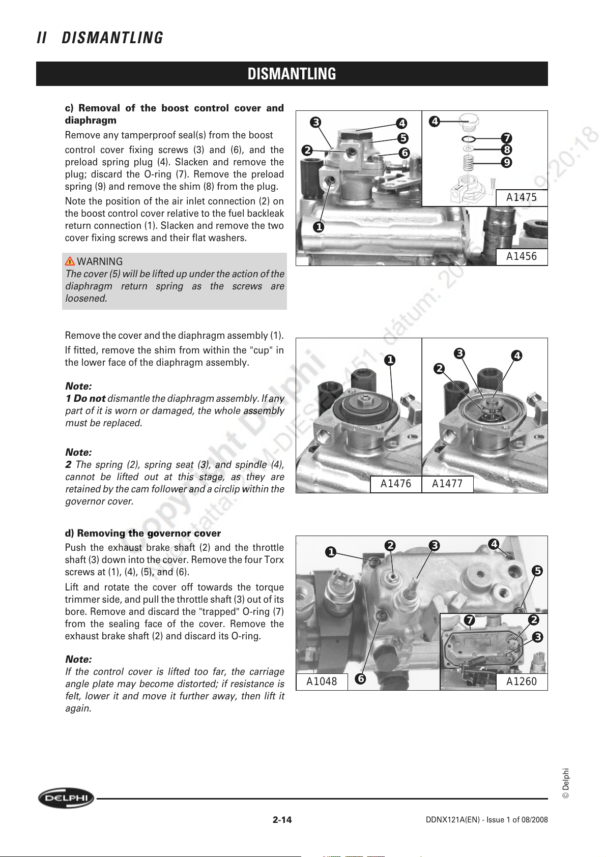
a) Spring end components
If fitted, remove the plastic sealing plug in the
preload plug (1) with a pointed tool. Unscrew and
remove the plug, using the appropriate size of Allen
key, and discard the O-ring (3). Remove the large
spring (4), the spring plate (5) (if fitted), and the
small spring (6) (if fitted). Remove shim (2) from
inside preload plug.
Note:
1 The preload plug fitted to later pumps may be
chamfered at its outer end, to prevent unauthorised
tampering.
Note:
2 It may be necessary to re-position the pump on
the Hydraclamp mounting plate to gain access to
the preload plug.
b) Removal of the governor control cover
If no boost control is fitted, the cam follower will be
pivoted on a spindle, which is formed as a part of a
pivot plug screwed into the governor control cover
(1). A plastic tamper proof plug will be fitted into the
hexagon hole in the plug and must be removed for
fitment of the appropriate Allen key. If the pivot-
plug is to be removed, slacken it by no more than
one turn before removal of the governor control
cover (to avoid the risk of damage to internal
components).
1
2
3
4
5
6
A1467
1
A1466
1
© Delphi
DDNX121A(EN) - Issue 1 of 08/2008
A1473
2-13
Page 28
II DISMANTLING
c) Removal of the boost control cover and
diaphragm
Remove any tamperproof seal(s) from the boost
control cover fixing screws (3) and (6), and the
preload spring plug (4). Slacken and remove the
plug; discard the O-ring (7). Remove the preload
spring (9) and remove the shim (8) from the plug.
Note the position of the air inlet connection (2) on
the boost control cover relative to the fuel backleak
return connection (1). Slacken and remove the two
cover fixing screws and their flat washers.
DISMANTLING
3
2
1
4
5
4
7
6
8
9
A1475
WARNING
The cover (5) will be lifted up under the action of the
diaphragm return spring as the screws are
loosened.
Remove the cover and the diaphragm assembly (1).
If fitted, remove the shim from within the "cup" in
the lower face of the diaphragm assembly.
Note:
1 Do not dismantle the diaphragm assembly. If any
part of it is worn or damaged, the whole assembly
must be replaced.
Note:
2 The spring (2), spring seat (3), and spindle (4),
cannot be lifted out at this stage, as they are
retained by the cam follower and a circlip within the
governor cover.
d) Removing the governor cover
Push the exhaust brake shaft (2) and the throttle
shaft (3) down into the cover. Remove the four Torx
screws at (1), (4), (5), and (6).
Lift and rotate the cover off towards the torque
trimmer side, and pull the throttle shaft (3) out of its
bore. Remove and discard the "trapped" O-ring (7)
from the sealing face of the cover. Remove the
exhaust brake shaft (2) and discard its O-ring.
A1456
1
3
2
4
A1477A1476
1
32
4
5
7
2
3
Note:
If the control cover is lifted too far, the carriage
angle plate may become distorted; if resistance is
felt, lower it and move it further away, then lift it
again.
2-14
A1048
6
DDNX121A(EN) - Issue 1 of 08/2008
A1260
© Delphi
Page 29
DISMANTLING
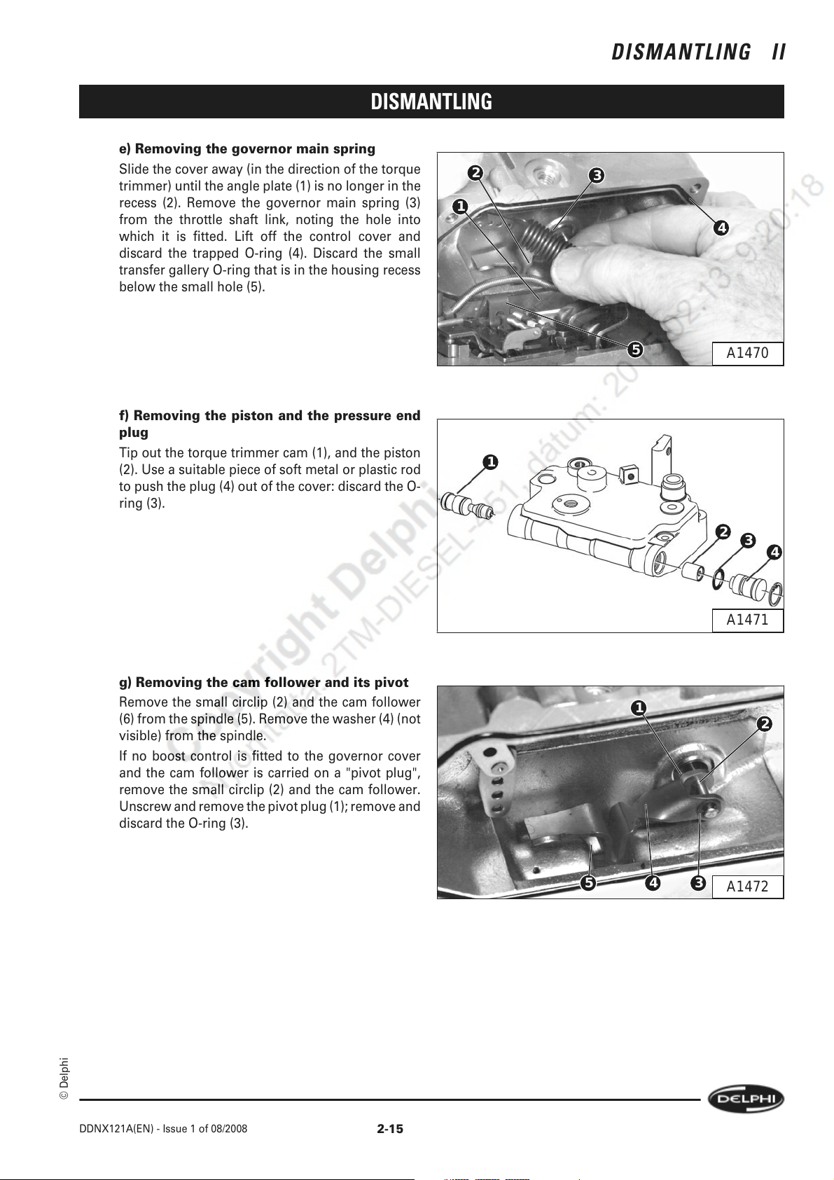
e) Removing the governor main spring
Slide the cover away (in the direction of the torque
trimmer) until the angle plate (1) is no longer in the
recess (2). Remove the governor main spring (3)
from the throttle shaft link, noting the hole into
which it is fitted. Lift off the control cover and
discard the trapped O-ring (4). Discard the small
transfer gallery O-ring that is in the housing recess
below the small hole (5).
DISMANTLING II
2
1
3
4
f) Removing the piston and the pressure end
plug
Tip out the torque trimmer cam (1), and the piston
(2). Use a suitable piece of soft metal or plastic rod
to push the plug (4) out of the cover: discard the O-
ring (3).
g) Removing the cam follower and its pivot
Remove the small circlip (2) and the cam follower
(6) from the spindle (5). Remove the washer (4) (not
visible) from the spindle.
If no boost control is fitted to the governor cover
and the cam follower is carried on a "pivot plug",
remove the small circlip (2) and the cam follower.
Unscrew and remove the pivot plug (1); remove and
discard the O-ring (3).
5
1
A1470
2
3
4
A1471
1
2
© Delphi
DDNX121A(EN) - Issue 1 of 08/2008
2-15
5 4 3
A1472
Page 30
II DISMANTLING
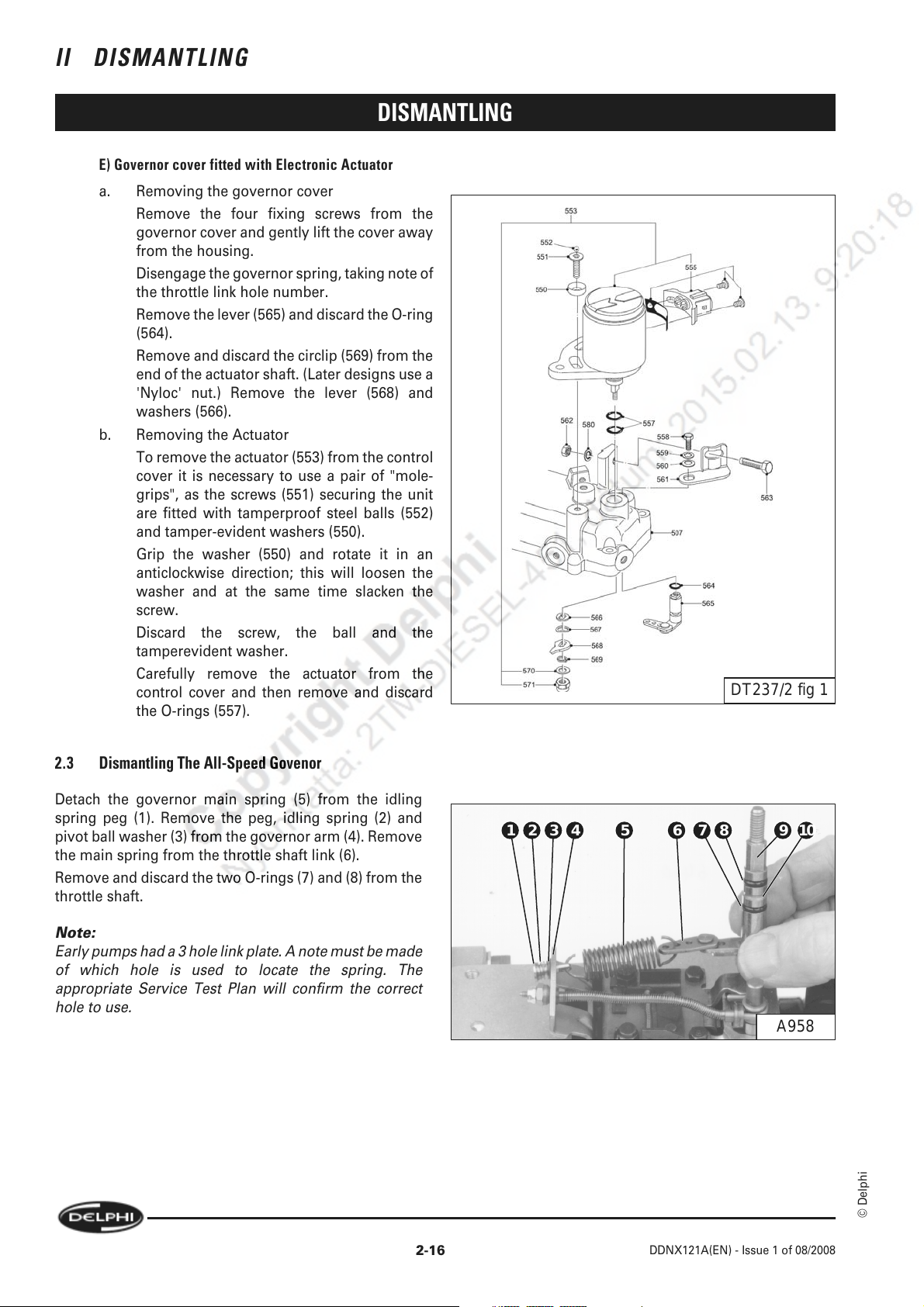
E) Governor cover fitted with Electronic Actuator
a. Removing the governor cover
Remove the four fixing screws from the
governor cover and gently lift the cover away
from the housing.
Disengage the governor spring, taking note of
the throttle link hole number.
Remove the lever (565) and discard the O-ring
(564).
Remove and discard the circlip (569) from the
end of the actuator shaft. (Later designs use a
'Nyloc' nut.) Remove the lever (568) and
washers (566).
b. Removing the Actuator
To remove the actuator (553) from the control
cover it is necessary to use a pair of "mole-
grips", as the screws (551) securing the unit
are fitted with tamperproof steel balls (552)
and tamper-evident washers (550).
Grip the washer (550) and rotate it in an
anticlockwise direction; this will loosen the
washer and at the same time slacken the
screw.
Discard the screw, the ball and the
tamperevident washer.
Carefully remove the actuator from the
control cover and then remove and discard
the O-rings (557).
DISMANTLING
DT237/2 fig 1
2.3 Dismantling The All-Speed Govenor
Detach the governor main spring (5) from the idling
spring peg (1). Remove the peg, idling spring (2) and
pivot ball washer (3) from the governor arm (4). Remove
the main spring from the throttle shaft link (6).
Remove and discard the two O-rings (7) and (8) from the
throttle shaft.
Note:
Early pumps had a 3 hole link plate. A note must be made
of which hole is used to locate the spring. The
appropriate Service Test Plan will confirm the correct
hole to use.
10987654321
A958
© Delphi
2-16
DDNX121A(EN) - Issue 1 of 08/2008
Page 31
DISMANTLING
2.4 Removing The Control Bracket And Arm Assembly
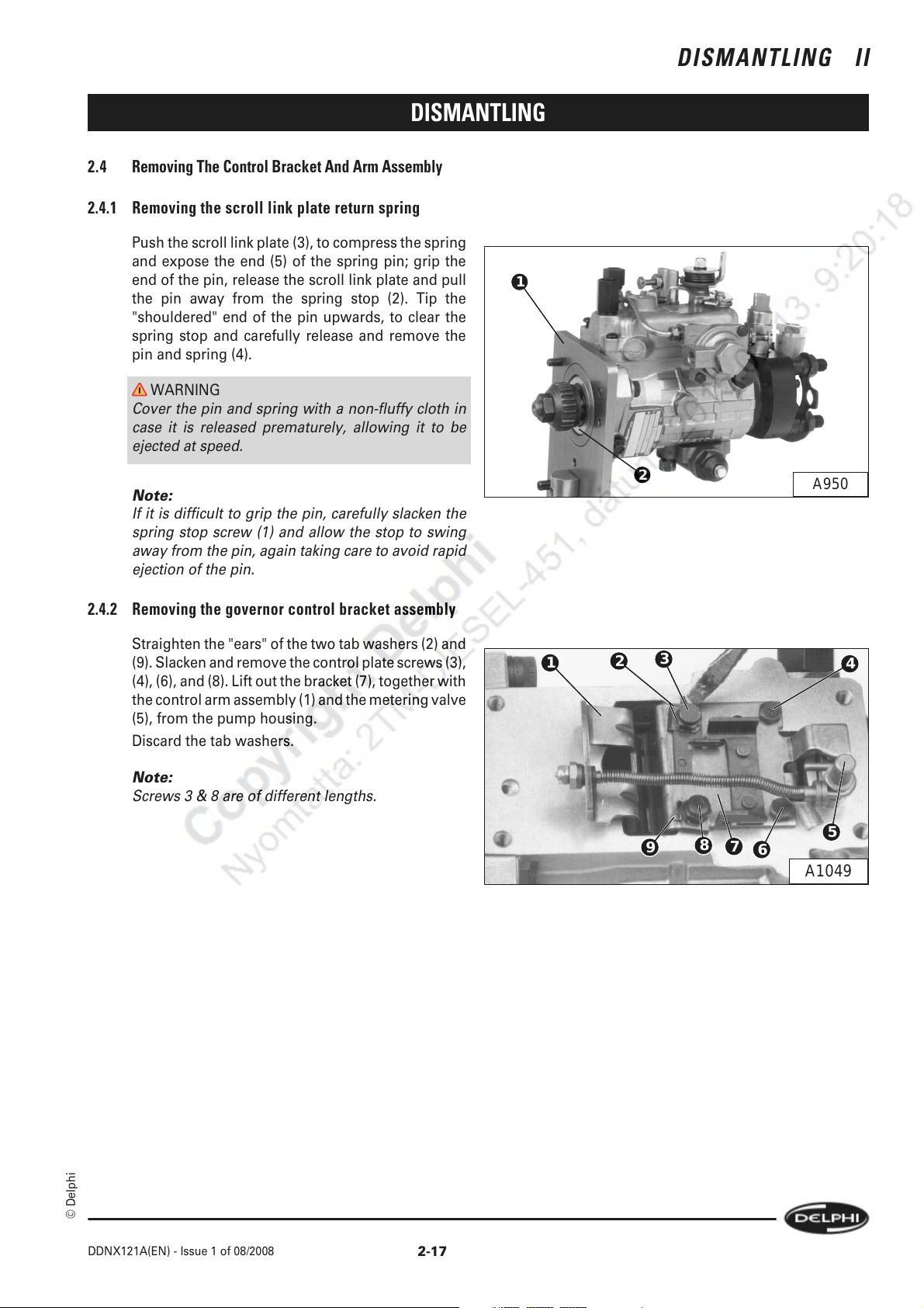
2.4.1 Removing the scroll link plate return spring
Push the scroll link plate (3), to compress the spring
and expose the end (5) of the spring pin; grip the
end of the pin, release the scroll link plate and pull
the pin away from the spring stop (2). Tip the
"shouldered" end of the pin upwards, to clear the
spring stop and carefully release and remove the
pin and spring (4).
WARNING
Cover the pin and spring with a non-fluffy cloth in
case it is released prematurely, allowing it to be
ejected at speed.
DISMANTLING II
1
Note:
If it is difficult to grip the pin, carefully slacken the
spring stop screw (1) and allow the stop to swing
away from the pin, again taking care to avoid rapid
ejection of the pin.
2.4.2 Removing the governor control bracket assembly
Straighten the "ears" of the two tab washers (2) and
(9). Slacken and remove the control plate screws (3),
(4), (6), and (8). Lift out the bracket (7), together with
the control arm assembly (1) and the metering valve
(5), from the pump housing.
Discard the tab washers.
Note:
Screws 3 & 8 are of different lengths.
2
3
1
2
8
9
7
6
A950
4
5
A1049
© Delphi
DDNX121A(EN) - Issue 1 of 08/2008
2-17
Page 32
II DISMANTLING
DISMANTLING
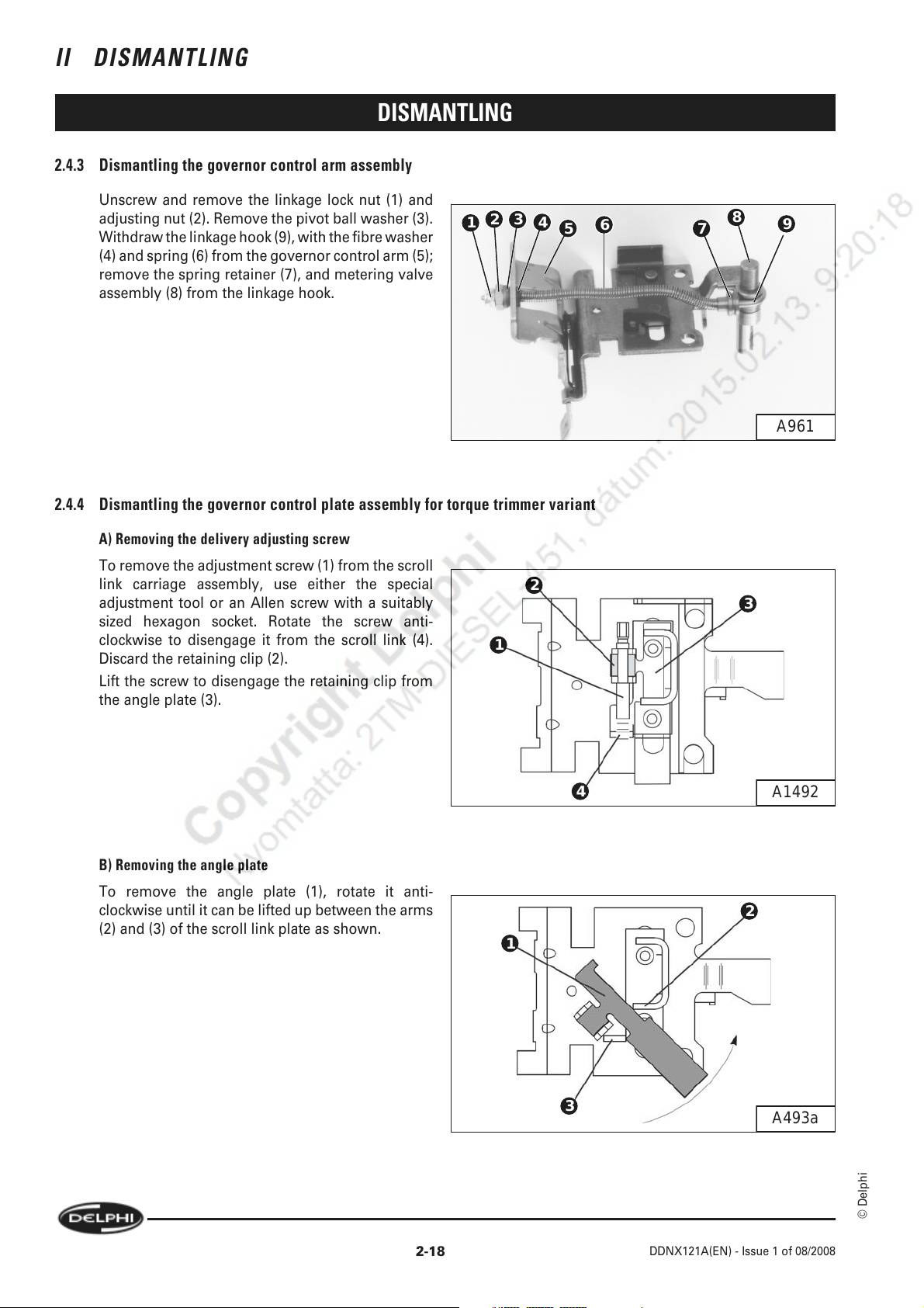
2.4.3 Dismantling the governor control arm assembly
Unscrew and remove the linkage lock nut (1) and
adjusting nut (2). Remove the pivot ball washer (3).
Withdraw the linkage hook (9), with the fibre washer
(4) and spring (6) from the governor control arm (5);
remove the spring retainer (7), and metering valve
assembly (8) from the linkage hook.
2.4.4 Dismantling the governor control plate assembly for torque trimmer variant
2
3
1
4
5
6
8
7
9
A961
A) Removing the delivery adjusting screw
To remove the adjustment screw (1) from the scroll
link carriage assembly, use either the special
adjustment tool or an Allen screw with a suitably
sized hexagon socket. Rotate the screw anti-
clockwise to disengage it from the scroll link (4).
Discard the retaining clip (2).
Lift the screw to disengage the retaining clip from
the angle plate (3).
B) Removing the angle plate
To remove the angle plate (1), rotate it anti-
clockwise until it can be lifted up between the arms
(2) and (3) of the scroll link plate as shown.
2
3
1
4
1
A1492
2
2-18
3
A493a
© Delphi
DDNX121A(EN) - Issue 1 of 08/2008
Page 33

DISMANTLING
2.5 High Pressure Outlets Assembly, Electric Shut-off Solenoid (ESOS) & Transfer Pump
2.5.1 High pressure outlets
Remove all the nuts (1), (2), (4), and (5) securing the
clamping plate (3) to the outlet connections, and
remove the plate.
If fitted, remove the four support plate screws at
position (6) and (8) and the pump-to-engine support
bracket (7).
Unscrew and remove each high pressure outlet,
using a long-reach socket. Remove and discard the
seating washer from the bottom of each outlet bore.
The high pressure outlets may be pressurising
valves which are factory-sealed units and cannot be
serviced. Alternatively the outlets may contain
delivery valves which must be retained in their
matched seat / valve pairs.
Remove the delivery valves, delivery valve springs
and pegs.
Delivery valve holders
must be discarded.
5
A962
3
4
DISMANTLING II
1
2
8
A985b
6
7
2.5.2 Endplate assembly
A) Removing the endplate assembly
If fitted, unscrew and remove the accumulator (7);
discard the O-rings (5) and (6).
Slacken, but do not remove, the fuel inlet
connection (1). Slacken and remove the four
endplate screws (2), and (4) and remove the
endplate assembly (3) complete.
5
EVD017
6
7
4
1
2
3
A963
© Delphi
DDNX121A(EN) - Issue 1 of 08/2008
2-19
Page 34
II DISMANTLING
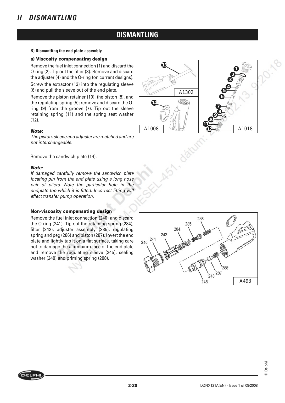
B) Dismantling the end plate assembly
a) Viscosity compensating design
Remove the fuel inlet connection (1) and discard the
O-ring (2). Tip out the filter (3). Remove and discard
the adjuster (4) and the O-ring (on current designs).
Screw the extractor (13) into the regulating sleeve
(6) and pull the sleeve out of the end plate.
Remove the piston retainer (10), the piston (8), and
the regulating spring (5); remove and discard the O-
ring (9) from the groove (7). Tip out the sleeve
retaining spring (11) and the spring seat washer
(12).
Note:
The piston, sleeve and adjuster are matched and are
not interchangeable.
Remove the sandwich plate (14).
DISMANTLING
14
13
A1302
11
12
10
1
2
3
4
5
6
7
8
9
A1018A1008
Note:
If damaged carefully remove the sandwich plate
locating pin from the end plate using a long nose
pair of pliers. Note the particular hole in the
endplate too which it is fitted. Incorrect fitting will
effect transfer pump operation.
Non-viscosity compensating design
Remove the fuel inlet connection (240) and discard
the O-ring (241). Tip out the retaining spring (284),
filter (242), adjuster assembly (285), regulating
spring and peg (286) and piston (287). Invert the end
plate and lightly tap it on a flat surface, taking care
not to damage the aluminium face of the end plate
and remove the regulating sleeve (245), sealing
washer (248) and priming spring (288).
A493
2-20
© Delphi
DDNX121A(EN) - Issue 1 of 08/2008
Page 35
DISMANTLING
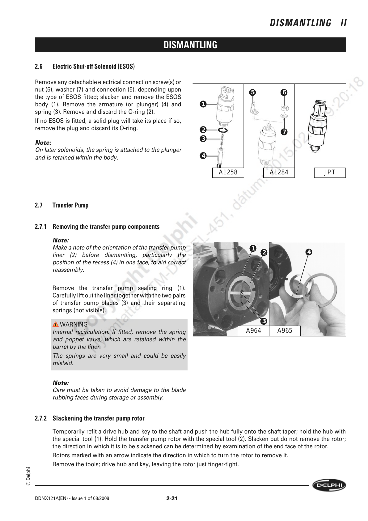
2.6 Electric Shut-off Solenoid (ESOS)
Remove any detachable electrical connection screw(s) or
nut (6), washer (7) and connection (5), depending upon
the type of ESOS fitted; slacken and remove the ESOS
body (1). Remove the armature (or plunger) (4) and
spring (3). Remove and discard the O-ring (2).
If no ESOS is fitted, a solid plug will take its place if so,
remove the plug and discard its O-ring.
Note:
On later solenoids, the spring is attached to the plunger
and is retained within the body.
DISMANTLING II
65
1
2
3
4
7
JPTA1258 A1284
2.7 Transfer Pump
2.7.1 Removing the transfer pump components
Note:
Make a note of the orientation of the transfer pump
liner (2) before dismantling, particularly the
position of the recess (4) in one face, to aid correct
reassembly.
Remove the transfer pump sealing ring (1).
Carefully lift out the liner together with the two pairs
of transfer pump blades (3) and their separating
springs (not visible).
WARNING
Internal recirculation. If fitted, remove the spring
and poppet valve, which are retained within the
barrel by the liner.
The springs are very small and could be easily
mislaid.
Note:
Care must be taken to avoid damage to the blade
rubbing faces during storage or assembly.
1
2
3
4
A965A964
2.7.2 Slackening the transfer pump rotor
Temporarily refit a drive hub and key to the shaft and push the hub fully onto the shaft taper; hold the hub with
the special tool (1). Hold the transfer pump rotor with the special tool (2). Slacken but do not remove the rotor;
the direction in which it is to be slackened can be determined by examination of the end face of the rotor.
Rotors marked with an arrow indicate the direction in which to turn the rotor to remove it.
Remove the tools; drive hub and key, leaving the rotor just finger-tight.
© Delphi
DDNX121A(EN) - Issue 1 of 08/2008
2-21
Page 36
II DISMANTLING
DISMANTLING
2.8 Advance Device
DP200 utilises a number of different advance devices. They fall into two main categories;
a.
Single piston design.
Direct actuation of the cam-ring by an advance piston operated by transfer pressure and controlled by a
combination of spring and cambox pressure.
b.
Servo piston design.
Indirect actuation of the cam-ring by an advance piston via a servo valve operated by transfer pressure and
controlled by a combination of spring and cambox pressure.
Each of these two types may be fitted with cold start timing retard with or without a wax motor mechanism.
2.8.1 Single piston design with 2 bolt cold advance (CA)
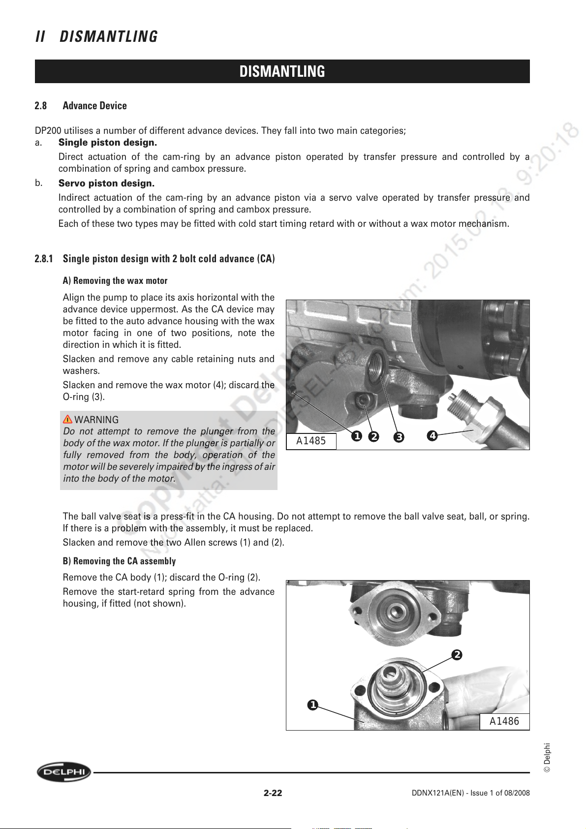
A) Removing the wax motor
Align the pump to place its axis horizontal with the
advance device uppermost. As the CA device may
be fitted to the auto advance housing with the wax
motor facing in one of two positions, note the
direction in which it is fitted.
Slacken and remove any cable retaining nuts and
washers.
Slacken and remove the wax motor (4); discard the
O-ring (3).
WARNING
Do not attempt to remove the plunger from the
body of the wax motor. If the plunger is partially or
fully removed from the body, operation of the
motor will be severely impaired by the ingress of air
into the body of the motor.
The ball valve seat is a press-fit in the CA housing. Do not attempt to remove the ball valve seat, ball, or spring.
If there is a problem with the assembly, it must be replaced.
Slacken and remove the two Allen screws (1) and (2).
B) Removing the CA assembly
Remove the CA body (1); discard the O-ring (2).
Remove the start-retard spring from the advance
housing, if fitted (not shown).
A1485
1
1
2
3
4
2
A1486
2-22
© Delphi
DDNX121A(EN) - Issue 1 of 08/2008
Page 37
DISMANTLING
C) Dismantling of the CA piston assembly
Remove the piston assembly from within the CA
housing (1). Grip the piston (2) lightly in a vice fitted
with soft jaws. With a suitable screwdriver, slacken
and remove the screw (9) and remove the phase
plate (8), stop plug (7), stop tube (6), outer spring
(5), inner spring (4), and shims (3). Remove the
piston from the vice.
WARNING
Caution: The screw will be under considerable
tension from the springs.
DISMANTLING II
9
8
7
6
5
4
3
2
1
Note:
Early pumps may be fitted with pistons that have
small "flats" to assist with clamping in the jaws of a
vice.
2.8.2 Servo piston design with 2 bolt Cold Advance
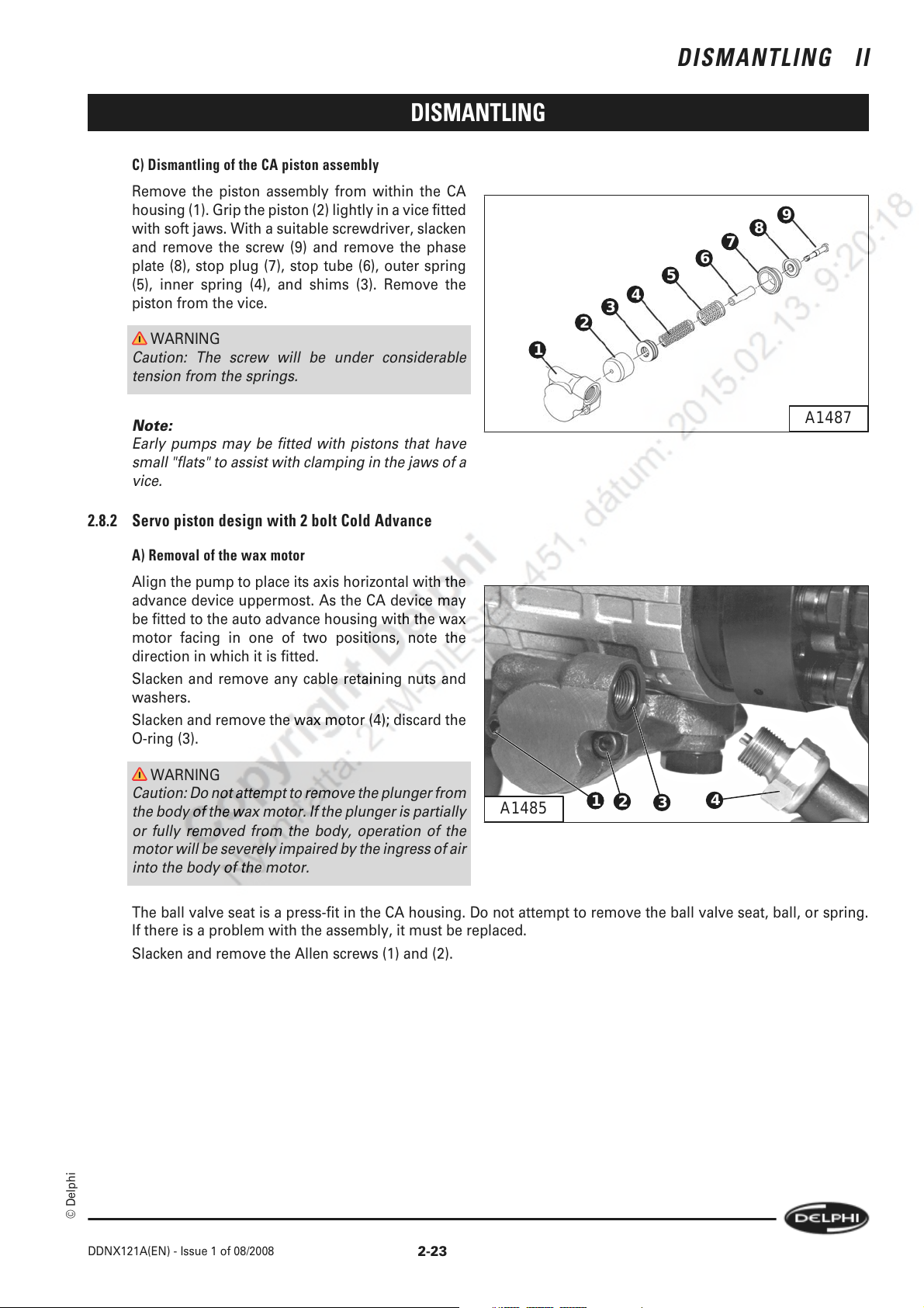
A) Removal of the wax motor
Align the pump to place its axis horizontal with the
advance device uppermost. As the CA device may
be fitted to the auto advance housing with the wax
motor facing in one of two positions, note the
direction in which it is fitted.
Slacken and remove any cable retaining nuts and
washers.
Slacken and remove the wax motor (4); discard the
O-ring (3).
WARNING
Caution: Do not attempt to remove the plunger from
the body of the wax motor. If the plunger is partially
or fully removed from the body, operation of the
motor will be severely impaired by the ingress of air
into the body of the motor.
A1485
A1487
1
2
3
4
The ball valve seat is a press-fit in the CA housing. Do not attempt to remove the ball valve seat, ball, or spring.
If there is a problem with the assembly, it must be replaced.
Slacken and remove the Allen screws (1) and (2).
© Delphi
DDNX121A(EN) - Issue 1 of 08/2008
2-23
Page 38

II DISMANTLING
B) Removing the CA assembly
Remove the CA body (302); discard the O-ring (308).
C) Removing the advance device
Slacken and remove the pressure end cap (325) and
O-ring (324).
An auxiliary spring may be fitted. (337)
Remove the advance housing cap-nut (417);
remove and discard the sealing washer (416).
Slacken the head locating fitting (420), or transfer
pressure damper (if fitted), no more than three
turns. Tap the advance housing (323) with a
softfaced mallet to free it from the gasket (415).
Remove the head locating fitting and then the
advance housing, complete with the piston. Discard
the gasket (415).
If fitted, carefully remove the spring ring (421)
retaining the lock-off ball (422) in the head locating
fitting and remove the ball. Discard the spring ring.
Remove and discard the split nylon ring (418), if
fitted, and the O-rings (419) from the head locating
fitting.
The piston sleeve (310) and piston (326) may still be
retained within the housing (302). Remove the
piston and one of the O-rings (309), then lightly grip
the housing in a vice fitted with soft jaws and with
a suitable flat bladed screwdriver lever out the
sleeve using the O-ring groove. Discard the
remaining O-ring (309).
DISMANTLING
1
DT167 fig 1
2-24
© Delphi
DDNX121A(EN) - Issue 1 of 08/2008
Page 39
DISMANTLING
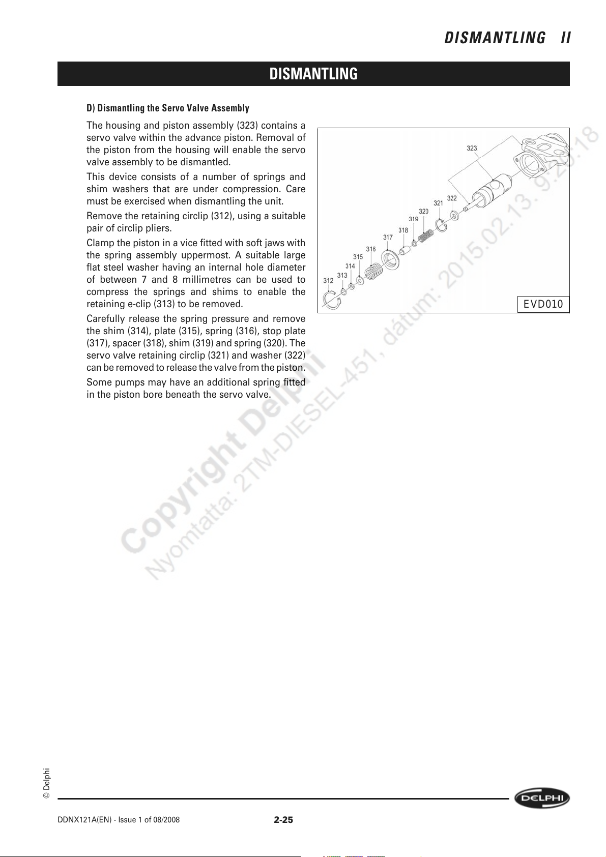
D) Dismantling the Servo Valve Assembly
The housing and piston assembly (323) contains a
servo valve within the advance piston. Removal of
the piston from the housing will enable the servo
valve assembly to be dismantled.
This device consists of a number of springs and
shim washers that are under compression. Care
must be exercised when dismantling the unit.
Remove the retaining circlip (312), using a suitable
pair of circlip pliers.
Clamp the piston in a vice fitted with soft jaws with
the spring assembly uppermost. A suitable large
flat steel washer having an internal hole diameter
of between 7 and 8 millimetres can be used to
compress the springs and shims to enable the
retaining e-clip (313) to be removed.
Carefully release the spring pressure and remove
the shim (314), plate (315), spring (316), stop plate
(317), spacer (318), shim (319) and spring (320). The
servo valve retaining circlip (321) and washer (322)
can be removed to release the valve from the piston.
Some pumps may have an additional spring fitted
in the piston bore beneath the servo valve.
DISMANTLING II
EVD010
© Delphi
DDNX121A(EN) - Issue 1 of 08/2008
2-25
Page 40
II DISMANTLING
DISMANTLING
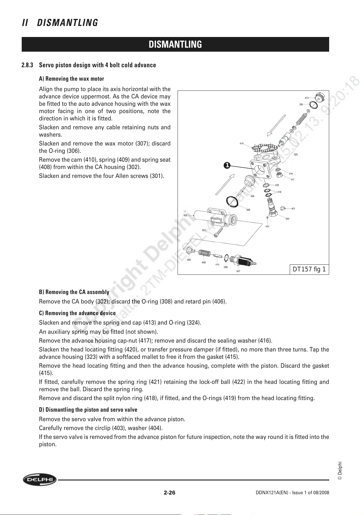
2.8.3 Servo piston design with 4 bolt cold advance
A) Removing the wax motor
Align the pump to place its axis horizontal with the
advance device uppermost. As the CA device may
be fitted to the auto advance housing with the wax
motor facing in one of two positions, note the
direction in which it is fitted.
Slacken and remove any cable retaining nuts and
washers.
Slacken and remove the wax motor (307); discard
the O-ring (306).
Remove the cam (410), spring (409) and spring seat
(408) from within the CA housing (302).
Slacken and remove the four Allen screws (301).
1
DT157 fig 1
B) Removing the CA assembly
Remove the CA body (302); discard the O-ring (308) and retard pin (406).
C) Removing the advance device
Slacken and remove the spring end cap (413) and O-ring (324).
An auxiliary spring may be fitted (not shown).
Remove the advance housing cap-nut (417); remove and discard the sealing washer (416).
Slacken the head locating fitting (420), or transfer pressure damper (if fitted), no more than three turns. Tap the
advance housing (323) with a softfaced mallet to free it from the gasket (415).
Remove the head locating fitting and then the advance housing, complete with the piston. Discard the gasket
(415).
If fitted, carefully remove the spring ring (421) retaining the lock-off ball (422) in the head locating fitting and
remove the ball. Discard the spring ring.
Remove and discard the split nylon ring (418), if fitted, and the O-rings (419) from the head locating fitting.
D) Dismantling the piston and servo valve
Remove the servo valve from within the advance piston.
Carefully remove the circlip (403), washer (404).
If the servo valve is removed from the advance piston for future inspection, note the way round it is fitted into the
piston.
2-26
© Delphi
DDNX121A(EN) - Issue 1 of 08/2008
Page 41
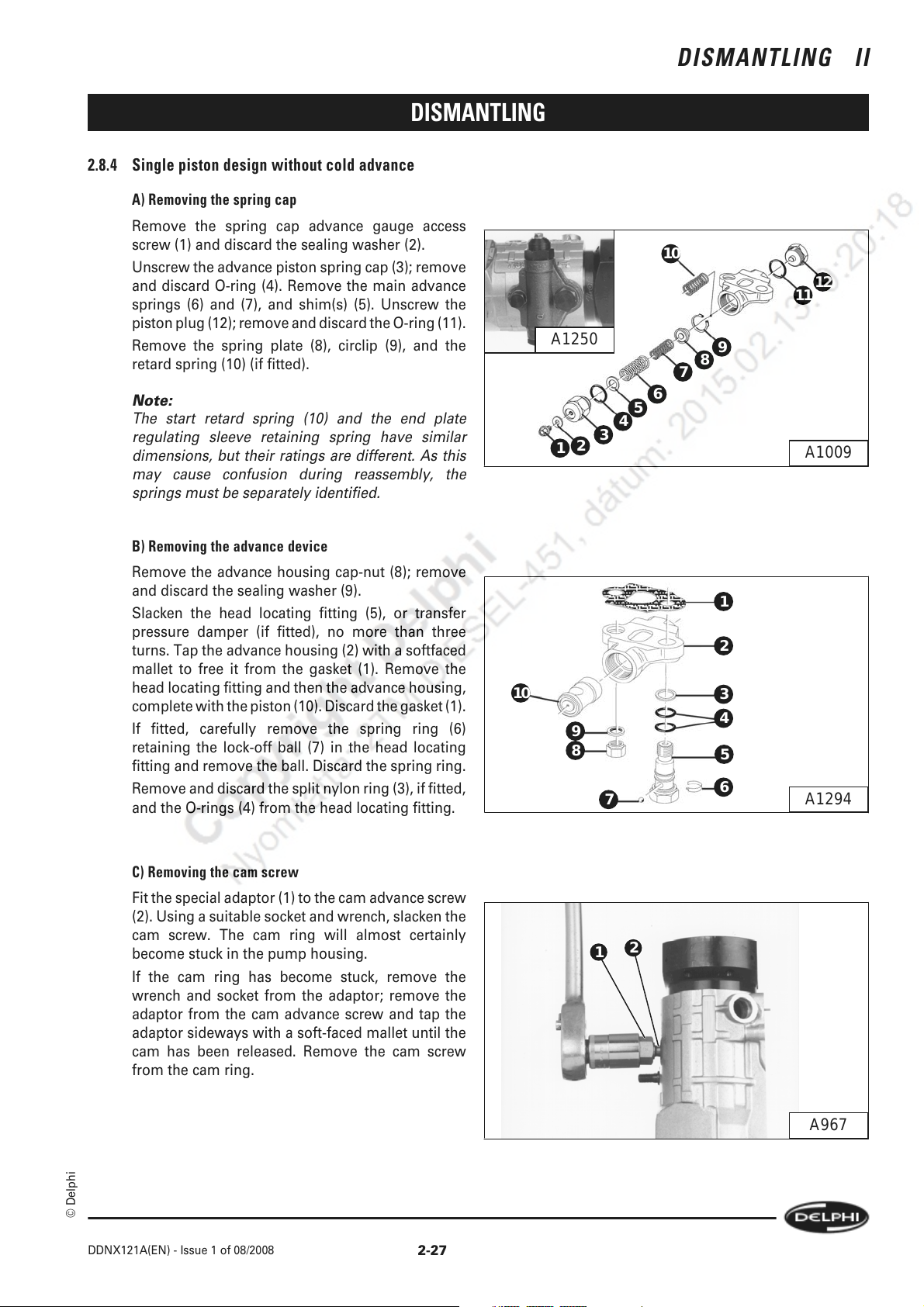
2.8.4 Single piston design without cold advance
A) Removing the spring cap
Remove the spring cap advance gauge access
screw (1) and discard the sealing washer (2).
Unscrew the advance piston spring cap (3); remove
and discard O-ring (4). Remove the main advance
springs (6) and (7), and shim(s) (5). Unscrew the
piston plug (12); remove and discard the O-ring (11).
Remove the spring plate (8), circlip (9), and the
retard spring (10) (if fitted).
Note:
The start retard spring (10) and the end plate
regulating sleeve retaining spring have similar
dimensions, but their ratings are different. As this
may cause confusion during reassembly, the
springs must be separately identified.
DISMANTLING
A1250
2
1
DISMANTLING II
10
12
11
9
8
7
6
5
4
3
A1009
B) Removing the advance device
Remove the advance housing cap-nut (8); remove
and discard the sealing washer (9).
Slacken the head locating fitting (5), or transfer
pressure damper (if fitted), no more than three
turns. Tap the advance housing (2) with a softfaced
mallet to free it from the gasket (1). Remove the
head locating fitting and then the advance housing,
complete with the piston (10). Discard the gasket (1).
If fitted, carefully remove the spring ring (6)
retaining the lock-off ball (7) in the head locating
fitting and remove the ball. Discard the spring ring.
Remove and discard the split nylon ring (3), if fitted,
and the O-rings (4) from the head locating fitting.
C) Removing the cam screw
Fit the special adaptor (1) to the cam advance screw
(2). Using a suitable socket and wrench, slacken the
cam screw. The cam ring will almost certainly
become stuck in the pump housing.
If the cam ring has become stuck, remove the
wrench and socket from the adaptor; remove the
adaptor from the cam advance screw and tap the
adaptor sideways with a soft-faced mallet until the
cam has been released. Remove the cam screw
from the cam ring.
10
1
2
3
9
8
7
2
1
4
5
6
A1294
© Delphi
DDNX121A(EN) - Issue 1 of 08/2008
A967
2-27
Page 42

II DISMANTLING
DISMANTLING
2.9 Removing The Head Locking Screws And Releasing The Hydraulic Head
2.9.1 Head locking screws
Slacken and remove the two head locking screws
(1) and (4); remove and discard the O-rings (2) and
(3) and the filters (not shown) in the inner ends of
the screws.
4
1
2
3
A1251
2.9.2 Removing and dismantling the LLA
a) Lock nut adjuster type
A differential valve for controlling light-load
advance may be fitted in place of one of the head
locking screws.
Slacken the locking nut (8) before removing the
valve body (3) from the pump. Remove the locking
nut and discard the seal (7). Remove the adjusting
screw (6) and spring (5). Tip out the ball (4). Remove
and discard the O-rings (1) and (2). Remove and
discard the filter if fitted.
b) Plug adjuster type
With a suitable pointed implement, prize out the
seal plug (278). Unscrew and remove the valve body
(219) from the pump and remove and discard the O-
rings (217 & 218). If fitted, remove and discard the
filter.
Unscrew and remove the adjuster (222) and discard
the O-ring (277). Tip out the spring (221) and ball
(220).
8
7
6
5
4
3
2
1
A1011b
2-28
DT228 fig 4
© Delphi
DDNX121A(EN) - Issue 1 of 08/2008
Page 43
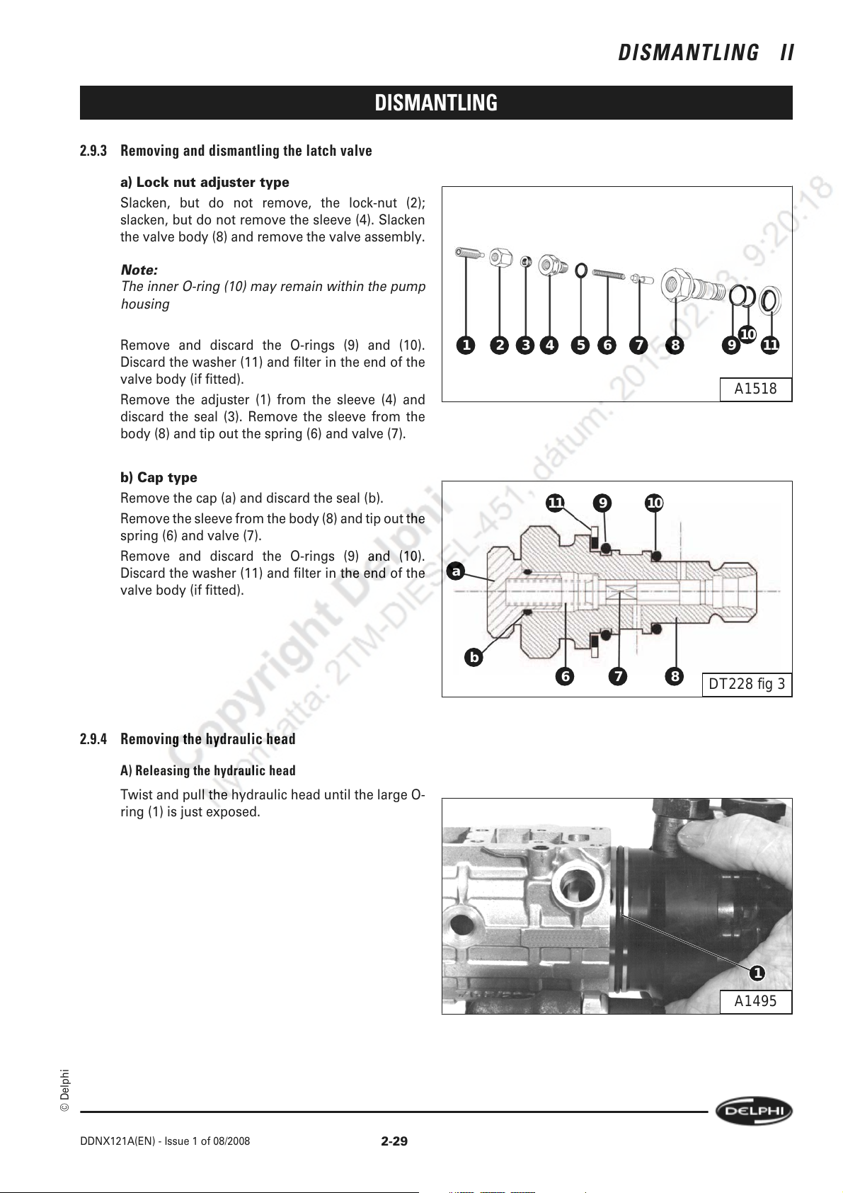
2.9.3 Removing and dismantling the latch valve
a) Lock nut adjuster type
Slacken, but do not remove, the lock-nut (2);
slacken, but do not remove the sleeve (4). Slacken
the valve body (8) and remove the valve assembly.
Note:
The inner O-ring (10) may remain within the pump
housing
DISMANTLING II
DISMANTLING
Remove and discard the O-rings (9) and (10).
Discard the washer (11) and filter in the end of the
valve body (if fitted).
Remove the adjuster (1) from the sleeve (4) and
discard the seal (3). Remove the sleeve from the
body (8) and tip out the spring (6) and valve (7).
b) Cap type
Remove the cap (a) and discard the seal (b).
Remove the sleeve from the body (8) and tip out the
spring (6) and valve (7).
Remove and discard the O-rings (9) and (10).
Discard the washer (11) and filter in the end of the
valve body (if fitted).
2.9.4 Removing the hydraulic head
10
11
987654321
A1518
11 109
a
b
876
DT228 fig 3
A) Releasing the hydraulic head
Twist and pull the hydraulic head until the large O-
ring (1) is just exposed.
© Delphi
DDNX121A(EN) - Issue 1 of 08/2008
1
A1495
2-29
Page 44

II DISMANTLING
B) Removing the hydraulic head
Realign the pump with its axis vertical, as shown,
and lift the head out of the pump housing; carefully
hold the plungers within the rotor and invert the
hydraulic head.
Note:
The rear scroll plate may adhere to the face of the
hydraulic head, if it does, remove it.
Place a plunger retaining cap (1) over the rotor;
remove and discard the large O-ring (2).
Keep the hydraulic head either in a bath of clean test
oil, ensuring that the exposed part of the rotor is
covered or in a clean plastic bag until it is required
for reassembly.
DISMANTLING
2
1
A1496
2.10 Drive Shaft
Remove the circlip (1) and thrust washer (2).
2.10.1 Dismantling the Zero Backlash Drive assembly
A) Removing the drive shaft
Push the drive shaft (1) carefully up through the
front bearing and remove it from the pump, holding
the rollers and shoes in position as the shaft is lifted
above the cam ring.
1
2
A970
2-30
1
A1497
© Delphi
DDNX121A(EN) - Issue 1 of 08/2008
Page 45

DISMANTLING
B) Removing the rollers and shoes
Remove the rollers and shoes, keeping them in their
matched pairs.
Note:
1 The roller shoe (1) in the rotor tang drive slot (2)
is longer than the others.
Note:
2 On some later designs, all 4 shoes are the same
length.
C) Dismantling the drive shaft assembly
DISMANTLING II
1
2
A1498
Note:
If the drive shaft is to be replaced, the components fitted to the shaft may be transferred if they are suitable for
further service.
D) Removing the catch plate and the support plate
If the roller cage and support blocks are to be
removed, place a suitable "tommy bar" (5) through
the transverse hole in the drive shaft; grip the drive
shaft lightly in a vice fitted with soft jaws, using the
tommy bar to resist the slackening torque. Use a
Torx screw bit and adaptor to remove the four catch
plate screws (2) and (4). Remove the catch plate (3)
and shoe plate (1).
2
1
3
4
5
A1499
© Delphi
DDNX121A(EN) - Issue 1 of 08/2008
2-31
Page 46

II DISMANTLING
E) Removing the support blocks
Note:
There is no support block in the groove into which
the hydraulic head rotor tang fits.
Invert the drive shaft and grip it very lightly, across
two diametrically opposite roller shoe gaps, in a
vice fitted with soft jaws. Use an extended Torx
screw adaptor to slacken the three screws (1), (2),
and (3). Remove the screws, their flat washers, and
the support blocks.
2.10.2 Dismantling the splined drive assembly
DISMANTLING
1
2
3
A1500
A) Removing the pump housing
Remove the pump from the Hydraclamp, carefully
holding it together, and place it on the bench with
the drive shaft uppermost.
Align a gap (1) in the weight cage with the centre
line of the pump so that the gap that will be
diametrically opposite will allow the weight cage to
pass the head of the advance device stud as the
pump housing is withdrawn.
Lift the housing off the drive shaft assembly.
B) Dismantling the drive shaft assembly
Lift the drive shaft (1), governor weight cage (2),
weights (3), and thrust sleeve (4) together from the
spacer (5), scroll plate (6), cam ring (7), and scroll
plate (8).
1
A1004
1
2
3
2-32
4
5
6
7
8
DDNX121A(EN) - Issue 1 of 08/2008
A972
© Delphi
Page 47

DISMANTLING
2.11 Dismantling The Hydraulic Head - Check And Cheek Plate Designs
2.11.1 Releasing the drive plate screws
Use the special tool (1) to hold the drive plate (3);
use a bi-hexagon socket to slacken and remove the
drive plate screws (2) and (4). Remove the drive
plate.
DISMANTLING II
2
1
3
4
A1290
2.11.2 Dismantling the rotor components
Remove the rollers and shoes (1), (3), (5) and (7).
Remove the dowel pins (2) and (4) fitted to the cheek
plate design and the upper cheek or check plate (6).
2.11.3 Removing the lower check or cheek plate
Retain the plungers in their respective bores with
the specified plastic clips (1), short lengths of nitrile
rubber tube, or small corks.
Unscrew and remove the transfer pump rotor, lift
out the hydraulic head rotor and remove the lower
check or cheek plate (2). Refit the rotor to the
hydraulic head, and then refit the transfer pump
rotor finger tight.
Store the head in a covered container filled with
clean test oil.
3
1
2
5
4
6
A975a
7
A1304
1
2
© Delphi
DDNX121A(EN) - Issue 1 of 08/2008
A1254
2-33
Page 48
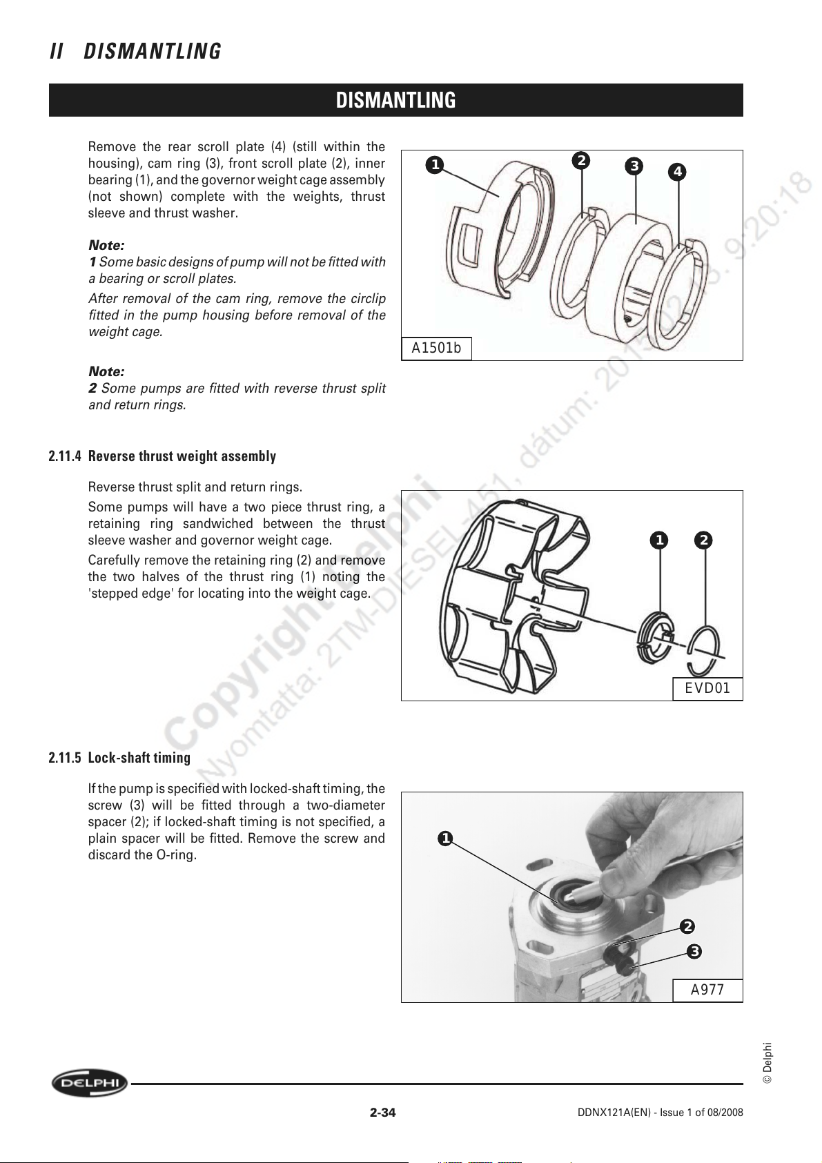
II DISMANTLING
DISMANTLING
Remove the rear scroll plate (4) (still within the
housing), cam ring (3), front scroll plate (2), inner
bearing (1), and the governor weight cage assembly
(not shown) complete with the weights, thrust
sleeve and thrust washer.
Note:
1 Some basic designs of pump will not be fitted with
a bearing or scroll plates.
After removal of the cam ring, remove the circlip
fitted in the pump housing before removal of the
weight cage.
Note:
2 Some pumps are fitted with reverse thrust split
and return rings.
2.11.4 Reverse thrust weight assembly
Reverse thrust split and return rings.
Some pumps will have a two piece thrust ring, a
retaining ring sandwiched between the thrust
sleeve washer and governor weight cage.
Carefully remove the retaining ring (2) and remove
the two halves of the thrust ring (1) noting the
'stepped edge' for locating into the weight cage.
1
A1501b
2
3
4
21
2.11.5 Lock-shaft timing
If the pump is specified with locked-shaft timing, the
screw (3) will be fitted through a two-diameter
spacer (2); if locked-shaft timing is not specified, a
plain spacer will be fitted. Remove the screw and
discard the O-ring.
EVD01
1
2
3
A977
© Delphi
2-34
DDNX121A(EN) - Issue 1 of 08/2008
Page 49
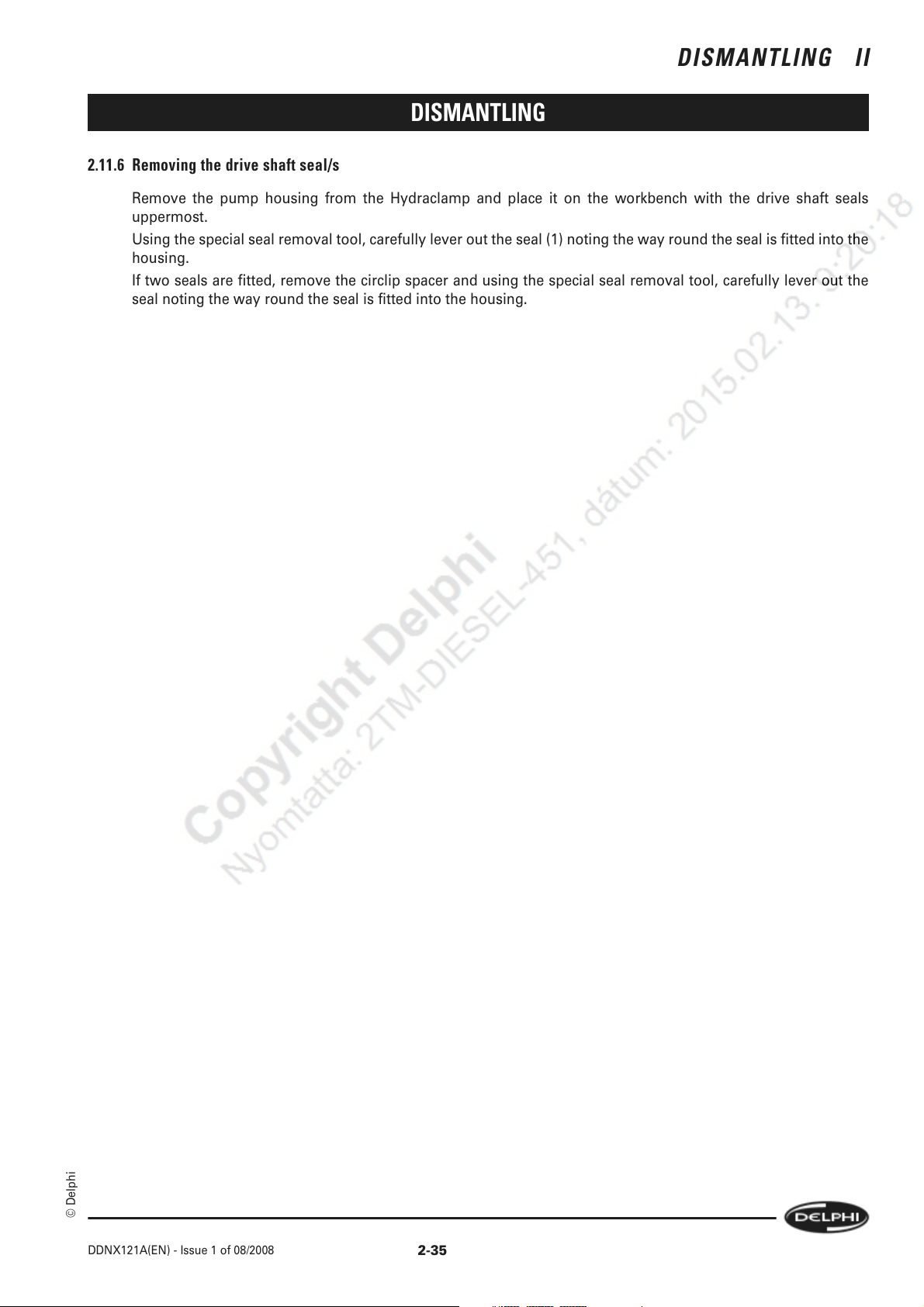
DISMANTLING II
DISMANTLING
2.11.6 Removing the drive shaft seal/s
Remove the pump housing from the Hydraclamp and place it on the workbench with the drive shaft seals
uppermost.
Using the special seal removal tool, carefully lever out the seal (1) noting the way round the seal is fitted into the
housing.
If two seals are fitted, remove the circlip spacer and using the special seal removal tool, carefully lever out the
seal noting the way round the seal is fitted into the housing.
© Delphi
DDNX121A(EN) - Issue 1 of 08/2008
2-35
Page 50
II DISMANTLING
DISMANTLING
2-36
© Delphi
DDNX121A(EN) - Issue 1 of 08/2008
Page 51
COMPONENT INSPECTION AND RENEWAL III
COMPONENT INSPECTION AND RENEWAL
3.1 Cleaning
If water contamination is suspected, carry out an initial examination of all internal components before attempting any
further cleaning. Clean out all passageways in the head and rotor by flushing out with clean test oil.
Also inspect for unusual marking, deposits, odour, seal swelling in the housing, in which case degraded RME fuels may
be a factor.
3.2 GeneraL
3.2.1 Mated and matched assemblies
The hydraulic head and rotor should be separated and examined; they should be re-mated immediately after
examination and immersed in a covered bath of clean test oil until required for reassembly into the pump.
Note:
If light load advance is specified, the metering valve will be matched to the hydraulic head.
The following groups are matched and must be kept assembled in their sets:
Rollers and shoes
Advance housing and piston
Cam ring and scroll plates
Stop solenoid plunger and body
Regulating sleeve, piston and adjusting screw
Governor cover and torque control piston
If any part of a matched set is considered to be unfit for further service, the whole set must be replaced.
Note:
The pump housing drive shaft bush is not a service repair item; if the bearing is worn, the housing must be
replaced.
3.2.2 Examination and replacement
All components must be checked for corrosion, wear, or damage. Under service workshop conditions it is not
feasible to test individual parts or sub-assemblies to determine their suitability for further service. Close
examination of the areas vulnerable to damage, and interpretation of the results of tests prior to dismantling,
should indicate the condition of parts.
a.
Corrosion
Check for signs of corrosion or water ingress (rust or staining) damage to machined surfaces. These include
the pump housing, drive shaft, hydraulic head bore, metering valve and bore cam ring, scroll plates, cheek
plates end plate and auto-advance device mounting face.
b.
Wear
Inspect drive shaft splines and associated parts for wear or damage. If excessive end-float or radial play was
detected prior to pump strip-down, examine the drive shaft thrust washer and housing bearing thrust face,
governor backplate and thrust face of drive shaft, and governor drive splines, for wear.
c.
Damage
Inspect all parts for damage or bending due to abuse, especially external levers and controls.
© Delphi
DDNX121A(EN) - Issue 1 of 08/2008
3-37
Page 52
III COMPONENT INSPECTION AND RENEWAL
COMPONENT INSPECTION AND RENEWAL
3.2.3 Seals
Replace the advance device gasket and all O-ring seals, including the "trapped" O-ring in the governor cover face.
Note that overhaul kit does not include drive shaft seals, which are stocked as separate items.
When fitting new O-rings and oil seals, care must be taken to use protection caps to avoid damage to the seals.
O-rings must be dipped in clean test oil prior to being assembled. External seals must be lightly coated with the
specified grease. Where possible, inspect seals for small cuts after assembly.
3.3 Details
3.3.1 Hydraulic head rotor
Withdraw the rotor from the hydraulic head.
Examine the running surface very closely for signs of erosion, particularly the area around the delivery port. If
significant erosion is evident, the head and rotor assembly must be replaced. Also check the condition of the drive
tang on CP drive pumps.
3.3.2 Hydraulic head plungers
If damage to the plungers is suspected, carefully separate them from the rotor, one at a time, and inspect them
for scoring or other damage. Replace the hydraulic head if the plungers show severe scratching. Clean each
plunger with test oil and immediately replace it very carefully in its original bore, the same way round.
The recommended plastic retainer, or short lengths of clean nitrile rubber tubing, should be used to retain the
plungers in their bores.
Note:
1 The two pairs of plungers are of different lengths; the two longer plungers are fitted in line with the axis of the
rotor delivery port.
Note:
2 DP200 pumps specified with light-load advance will be fitted with "graded" metering valves. Refer to the
appropriate parts list for details.
3.3.3 Cam ring and scroll plates
Inspect the running surface of the cam ring and scroll plates for signs of breakdown of the leading face or apex
of the profile. If there are significant signs of pitting or "smearing" they must be replaced as a set. Smearing is the
result of failure of the surface due to abrasion or overloading, which may be due to excessive hydraulic pressure
(possibly caused by nozzle blockage).
3.3.4 Rollers and shoes
Inspect rollers and shoes for damage. Pay particular attention to the condition of the contact surfaces and check
that the rollers rotate freely in their shoes. If the cam ring has failed, the rollers and shoes may also have been
severely damaged. If satisfactory, rollers must be replaced in their original shoes.
3.3.5 Transfer pump
Check the blades for chips, scores or breakages.
Examine the blade springs for distortion Blades must be replaced in sets and must be of the same type as the
originals. Examine the rotor for wear or damage.
Examine the liner for corrosion or scoring and replace it if there are any signs of damage.
3-38
DDNX121A(EN) - Issue 1 of 08/2008
© Delphi
Page 53

COMPONENT INSPECTION AND RENEWAL III
COMPONENT INSPECTION AND RENEWAL
3.3.6 Endplate
Examine the inner face of the endplate for wear. Replace it if there is any significant scoring. If the sandwich plate
is scored or worn, it must be replaced and not reversed. The transfer pressure accumulator retainer must not be
protruding. Replace if faulty.
3.3.7 Control valves
Check all control valves for wear or scoring.
Examine the metering valve for "stepping" of the control slot edges and at the point where it enters the bore in
the hydraulic head. Check that the valve and the governor link pin are securely fixed in the bar and that the roller
is free to rotate on the pin and is not worn. Check the regulating sleeve and piston and differential valve for damage,
corrosion or blockage of orifices.
3.3.8 Delivery valves and cambox pressurising valves
Check for erosion or other damage to delivery valve assemblies. Replace them (as matched pairs) if necessary.
If movement of the cambox pressurising valve can be detected when shaken the spring may have collapsed, in
which case the whole assembly must be replaced, as it is factory-sealed.
3.3.9 High pressure outlet pressurising valves
Only the "ball" type of pressurising valve is used and, in the 7185-022 series, the balls should be either flush with
the outer face of the valve body or protrude by no more than 0,5 mm (see SIN DT312 for full details of both types
of valve).
3.3.10 Springs
Look for distorted or fractured springs. Very carefully examine the areas of contact with adjoining components
(spring pegs, throttle shaft links etc). Check that all springs specified in the Parts List for the pump are present.
3.3.11 Fittings and threads
Check all screws and nuts for damage. Check the cam advance screw flats, which may have been damaged by
careless application of the high tightening torque.
Check all threads for damage, especially on the transfer and distributor rotors, hydraulic head, cam advance screw
hole, studs, fuel inlet and return and high pressure outlet connections.
3.3.12 Linkages
Inspect all mechanical governor linkages, shafts, pivot pins and arms for wear, cracks or scoring of their mating
surfaces.
3.3.13 Control shafts
Examine control shafts and their associated bores in the governor cover for distortion, wear, looseness of joints
or elongation of spring anchor holes.
3.3.14 Drive shafts and associated components
Inspect the shaft for wear or damage, especially where the oil seal contacts the shaft. Check splines and keyways
for cracks or chipping. Check the tang slot on CP drive pumps.
Examine the thrust surfaces on the inner face of the pump housing and the weight cage for damage or scoring.
Examine the governor weight cage and weights for wear, cracks or damage. Ensure that the correct number and
type of governor weights are fitted.
© Delphi
DDNX121A(EN) - Issue 1 of 08/2008
3-39
Page 54
III COMPONENT INSPECTION AND RENEWAL
COMPONENT INSPECTION AND RENEWAL
3.3.15 Advance device
Examine the components for corrosion. If water has been present in the fuel it will tend to settle in the advance
housing. Check that the piston moves freely.
3.3.16 Levers and external controls
Examine all levers for cracks and for excessive wear at contact points.
3.3.17 Pump housing
Examine the housing for damage, especially to sealing surfaces. If the bearing is unfit for further service, the
housing must be replaced. If the small dowel pin, which locates the governor control cover, is damaged, it must
be replaced. If the advance device stud is damaged and requires replacement, remove it by using two suitable
nuts locked together. Fit a new stud using the same technique.
3.3.18 Governor control cover
Check the control shaft bores, stop screw threads, and adjusting screw seal spotfaces (anti-stall, maximum fuel
stop, and boost control). Check the boost control locating dowel pin. Check the torque trimmer piston bore.
3.3.19 Orifices
Examine all orifices for blockage and carefully clear any obstruction with dry compressed air.
3.3.20 Electric shut-off solenoid
Ensure that all the solenoid electrical parts are clean, especially the connection(s), and that the plunger is free in
its bore. Check that the flexible valve seat is in good condition, with no pitting or other damage, and that the spring
is not distorted. Check the coil for electrical continuity by measuring its resistance. Ensure that the solenoid is
completely dry and check insulation resistance between each terminal and the solenoid body (insulated return
solenoids only).
Note:
1 A few solenoids are specified to be operated only when there is a requirement to stop the engine.
Note:
2 If any fault is apparent in the stop solenoid assembly, the whole unit must be replaced.
3.3.21 Wax motor
If a pre-dismantling test of the injection pump indicates that the CA device is not operating correctly, carry out
the following test on the wax motor, out of the CA housing (no test is necessary if operation is according to the
Test Plan).
The motor may be tested for correct function by connecting it either to a fully charged 12 V battery, or to a stabilised
DC power supply set to 12.0 V and capable of supplying at least 3 A for at least 5 minutes. The test data refers to
12 V operation only - currents and times are significantly different for operation at 24 V. The motor is not polarity
sensitive.
Before testing, place the motor on a flat surface, with the spindle downwards, and press lightly on the motor for
about 15 seconds to ensure that the spindle is in its fully retracted position.
Clamp the motor, with its spindle facing upwards lightly in a vice fitted with soft jaws.
Note:
Early pumps may be fitted with pistons that have small flats to assist with clamping in the jaws of a vice.
3-40
DDNX121A(EN) - Issue 1 of 08/2008
© Delphi
Page 55
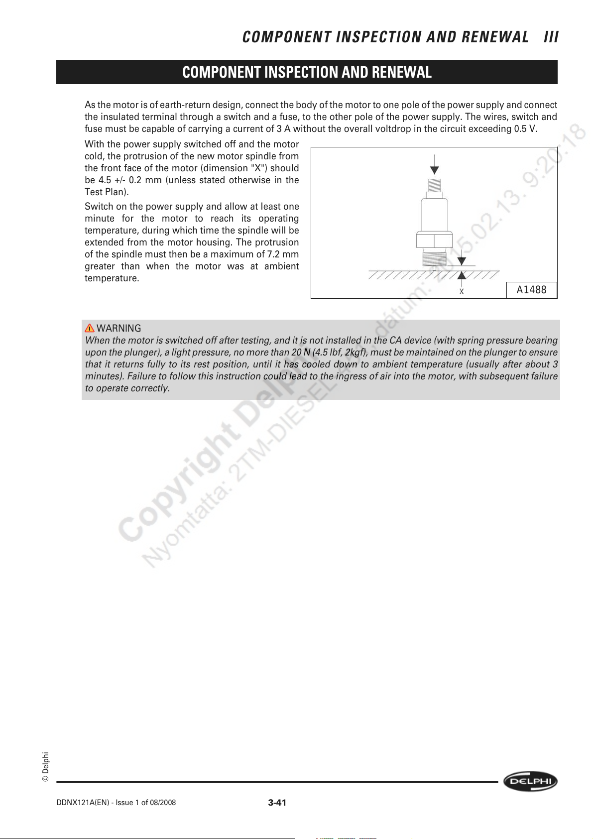
COMPONENT INSPECTION AND RENEWAL III
COMPONENT INSPECTION AND RENEWAL
As the motor is of earth-return design, connect the body of the motor to one pole of the power supply and connect
the insulated terminal through a switch and a fuse, to the other pole of the power supply. The wires, switch and
fuse must be capable of carrying a current of 3 A without the overall voltdrop in the circuit exceeding 0.5 V.
With the power supply switched off and the motor
cold, the protrusion of the new motor spindle from
the front face of the motor (dimension "X") should
be 4.5 +/- 0.2 mm (unless stated otherwise in the
Test Plan).
Switch on the power supply and allow at least one
minute for the motor to reach its operating
temperature, during which time the spindle will be
extended from the motor housing. The protrusion
of the spindle must then be a maximum of 7.2 mm
greater than when the motor was at ambient
temperature.
A1488
WARNING
When the motor is switched off after testing, and it is not installed in the CA device (with spring pressure bearing
upon the plunger), a light pressure, no more than 20 N (4.5 lbf, 2kgf), must be maintained on the plunger to ensure
that it returns fully to its rest position, until it has cooled down to ambient temperature (usually after about 3
minutes). Failure to follow this instruction could lead to the ingress of air into the motor, with subsequent failure
to operate correctly.
© Delphi
DDNX121A(EN) - Issue 1 of 08/2008
3-41
Page 56
III COMPONENT INSPECTION AND RENEWAL
COMPONENT INSPECTION AND RENEWAL
3-42
© Delphi
DDNX121A(EN) - Issue 1 of 08/2008
Page 57

REASSEMBLY IV
REASSEMBLY
4.1 Preparation
Before using thread-locking compound, if specified, ensure that the mating surfaces are completely oil-free and dry.
When reassembling pumps, it is important to use the correct overhaul kit. The relevant kit numbers can be found in the
Service Parts List.
Lightly lubricate all flexible seals and O-rings with clean test oil before fitment to their respective components. Always
use the correct protection cap when fitting new O-rings. Apply the specified grease to the drive shaft seal and the throttle
and exhaust brake shafts before assembly in their respective positions. Dip all internal components in clean test oil before
assembly.
Refer to the relevant Test Plan for details of special build items and any initial setting instructions.
Refer to Section 6 for all special tools and torque values.
The direction of rotation of the pump, as shown on the nameplate, is as viewed from the drive end.
4.2 Assembling The Hydraulic Head
Note:
1 Check the direction of the arrow on the distributor rotor head agrees with that of the arrow on the pump nameplate.
Note:
2 The plungers in four-plunger rotors must be fitted with the longer plungers opposite to each other and in line with the
distributor port in the rotor.
4.2.1 Rotor plug
If the rotor plug is loose or a leak along the thread
is suspected as a result of the pre-dismantling test,
the plug must be removed, replaced if necessary,
and re-sealed, using the following procedure:
Temporarily fit the two drive plate clamping screws
(4) and (5) into their holes in the rotor head, leaving
them finger tight. Leave the plunger clips (3) in
position, remove the transfer pump rotor and
carefully remove the distributor rotor from the
hydraulic head body, avoiding any contact with the
running surface of the rotor. Invert the rotor and
lightly clamp the screw heads in a vice fitted with
soft jaws.
Remove the plug screw, using the specified tool (1),
fitted with a straight Allen key (2) or relevant socket.
If the plug thread is damaged, replace the plug.
1
2
5
3
4
A979
Thoroughly degrease both the plug and rotor threads and smear the plug thread with a small amount of 'Loctite'
638. Refit the plug, using a new sealing washer, and tighten it to the specified torque.
Lubricate the rotor with clean test oil (but do not allow any oil in the vicinity of the plug) and refit the rotor to the
hydraulic head. Place the hydraulic head assembly in a clean environment until the recommended 'Locktite' curing
time has elapsed (typically, 6 hours at room temperature).
Note:
Do not attempt to accelerate the curing process by heating the hydraulic head assembly.
© Delphi
DDNX121A(EN) - Issue 1 of 08/2008
4-43
Page 58
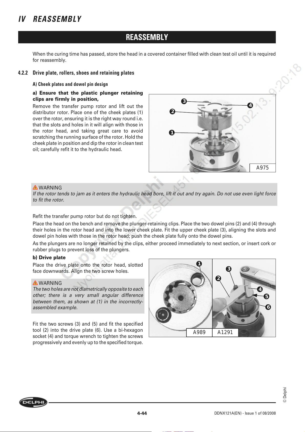
IV REASSEMBLY
REASSEMBLY
When the curing time has passed, store the head in a covered container filled with clean test oil until it is required
for reassembly.
4.2.2 Drive plate, rollers, shoes and retaining plates
A) Cheek plates and dowel pin design
a) Ensure that the plastic plunger retaining
clips are firmly in position,
Remove the transfer pump rotor and lift out the
distributor rotor. Place one of the cheek plates (1)
over the rotor, ensuring it is the right way round i.e.
that the slots and holes in it will align with those in
the rotor head, and taking great care to avoid
scratching the running surface of the rotor. Hold the
cheek plate in position and dip the rotor in clean test
oil; carefully refit it to the hydraulic head.
3
2
1
4
A975
WARNING
If the rotor tends to jam as it enters the hydraulic head bore, lift it out and try again. Do not use even light force
to fit the rotor.
Refit the transfer pump rotor but do not tighten.
Place the head on the bench and remove the plunger-retaining clips. Place the two dowel pins (2) and (4) through
their holes in the rotor head and into the lower cheek plate. Fit the upper cheek plate (3), aligning the slots and
dowel pin holes with those in the rotor head; push the cheek plate fully onto the dowel pins.
As the plungers are no longer retained by the clips, either proceed immediately to next section, or insert cork or
rubber plugs to prevent loss of the plungers.
b) Drive plate
Place the drive plate onto the rotor head, slotted
face downwards. Align the two screw holes.
WARNING
The two holes are not diametrically opposite to each
other; there is a very small angular difference
between them, as shown at (1) in the incorrectly-
assembled example.
Fit the two screws (3) and (5) and fit the specified
tool (2) into the drive plate (6). Use a bi-hexagon
socket (4) and torque wrench to tighten the screws
progressively and evenly up to the specified torque.
1
3
2
4
5
6
A1291A989
4-44
© Delphi
DDNX121A(EN) - Issue 1 of 08/2008
Page 59
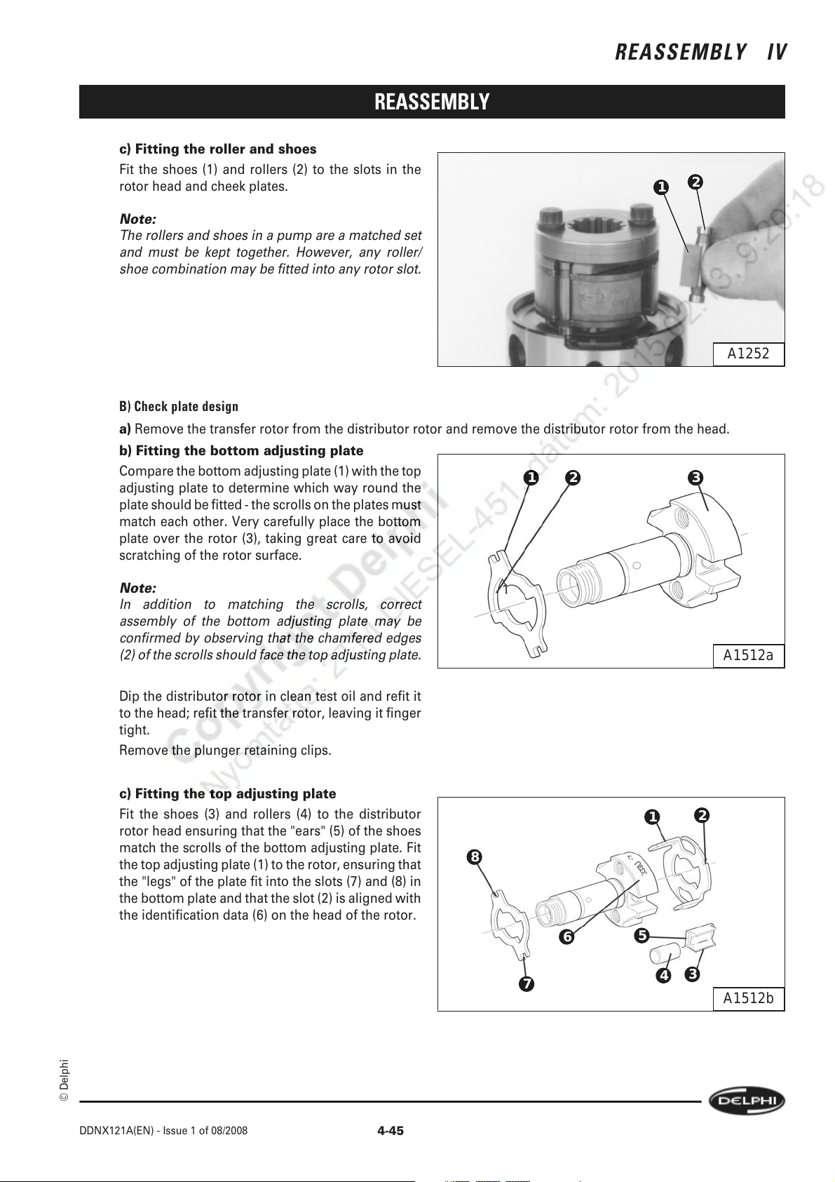
REASSEMBLY IV
REASSEMBLY
c) Fitting the roller and shoes
Fit the shoes (1) and rollers (2) to the slots in the
rotor head and cheek plates.
Note:
The rollers and shoes in a pump are a matched set
and must be kept together. However, any roller/
shoe combination may be fitted into any rotor slot.
B) Check plate design
a) Remove the transfer rotor from the distributor rotor and remove the distributor rotor from the head.
b) Fitting the bottom adjusting plate
Compare the bottom adjusting plate (1) with the top
adjusting plate to determine which way round the
plate should be fitted - the scrolls on the plates must
match each other. Very carefully place the bottom
plate over the rotor (3), taking great care to avoid
scratching of the rotor surface.
1 32
2
1
A1252
Note:
In addition to matching the scrolls, correct
assembly of the bottom adjusting plate may be
confirmed by observing that the chamfered edges
(2) of the scrolls should face the top adjusting plate.
Dip the distributor rotor in clean test oil and refit it
to the head; refit the transfer rotor, leaving it finger
tight.
Remove the plunger retaining clips.
c) Fitting the top adjusting plate
Fit the shoes (3) and rollers (4) to the distributor
rotor head ensuring that the "ears" (5) of the shoes
match the scrolls of the bottom adjusting plate. Fit
the top adjusting plate (1) to the rotor, ensuring that
the "legs" of the plate fit into the slots (7) and (8) in
the bottom plate and that the slot (2) is aligned with
the identification data (6) on the head of the rotor.
A1512a
1
8
6
7
5
2
3
4
A1512b
© Delphi
DDNX121A(EN) - Issue 1 of 08/2008
4-45
Page 60

IV REASSEMBLY
d) Alignment of the drive plate
In order to ensure correct alignment of the rotor
delivery port with the drive shaft keyway, the two
holes for the drive plate screws in the drive plate
and in the rotor are not on the same transverse
centreline. If necessary, turn the drive plate until the
holes are aligned.
To illustrate the difference, the drive plate is shown
deliberately incorrectly assembled.
Note:
The inner face of the driveplate has a machined
groove (see illus. A1512c item (3) over page) to
ensure that the "ears" of the roller shoes are not
trapped when the drive plate screws are tightened.
e) Fitting the drive plate
Fit the drive plate, aligning the screw holes correctly
with those in the rotor head.
Fit the drive plate screws, leaving them finger-tight.
Set the adjusting plates so that the slot (1) in the top
plate is approximately in the centre of the gap (2) in
the drive plate. The final position of the adjusting
plates will be set during testing.
REASSEMBLY
A989
1
2
3
A1512c
4-46
© Delphi
DDNX121A(EN) - Issue 1 of 08/2008
Page 61

REASSEMBLY
4.3 Drive Shaft
4.3.1 Zero backlash and splined drive with cheek plates.
A) Fitting the support blocks
If the drive shaft has been dismantled to its
component parts fit the support blocks to the
relevant slots, with their concave ends facing
radially outwards and their flat faces towards the
drive shaft. Secure them with the Torx screws (1),
(2), and (3) and flat washers.
Place the drive shaft in a vice fitted with soft jaws,
gripping it lightly across two diametrically opposite
slots. Tighten the screws to the specified torque
using an extended Torx bit (see Section 6).
Note:
1 Only use the minimum necessary clamping force.
DO NOT clamp on the polished inner bearing
surface (4).
REASSEMBLY IV
2
1
4
3
A1500
Note:
2 Later designs incorporate the lubrication groves in the drive shaft.
It is imperative that combinations of early and late designs do not result in a build where there is no
lubrication groove present.
A groove in both the shoe and drive shaft is permissible.
B) Fitting the shoe plate and roller catch plate
Remove the shaft from the vice and invert it. Fit a
small "tommy" bar (6) through the transverse hole
in the shaft; mount the shaft again in the vice fitted
with soft jaws, in such a position that the bar will
prevent rotation of the shaft as the catch plate
screws are tightened. Do not clamp the shaft on the
polished inner bearing surface (5), but clamp it
across the smaller diameter, very lightly.
Fit the shoe plate (1) and the roller catch plate (3)
and secure them with the four Torx screws (2) and
(4), tightened to the specified torque.
Note:
No washers are fitted under the screw heads.
2
1
3
4
5
6
A1499
© Delphi
DDNX121A(EN) - Issue 1 of 08/2008
4-47
Page 62
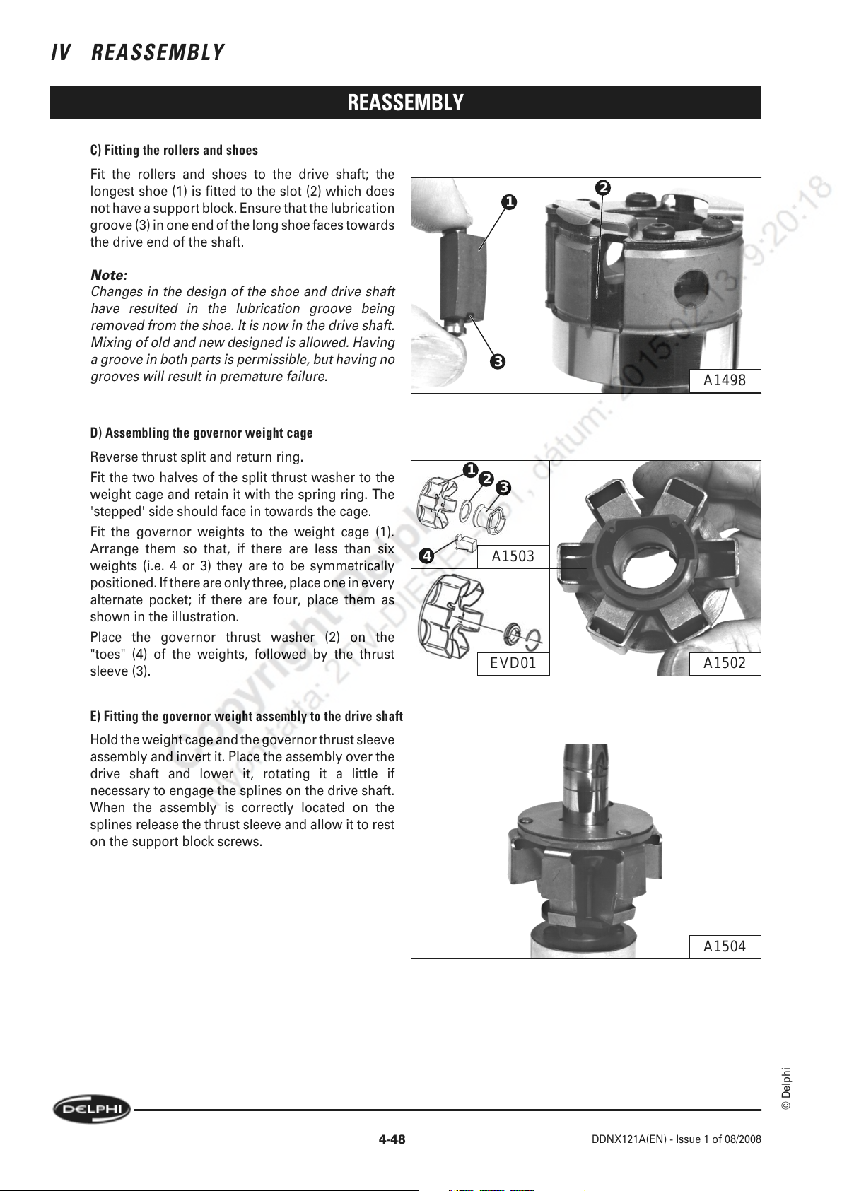
IV REASSEMBLY
C) Fitting the rollers and shoes
Fit the rollers and shoes to the drive shaft; the
longest shoe (1) is fitted to the slot (2) which does
not have a support block. Ensure that the lubrication
groove (3) in one end of the long shoe faces towards
the drive end of the shaft.
Note:
Changes in the design of the shoe and drive shaft
have resulted in the lubrication groove being
removed from the shoe. It is now in the drive shaft.
Mixing of old and new designed is allowed. Having
a groove in both parts is permissible, but having no
grooves will result in premature failure.
D) Assembling the governor weight cage
Reverse thrust split and return ring.
Fit the two halves of the split thrust washer to the
weight cage and retain it with the spring ring. The
'stepped' side should face in towards the cage.
Fit the governor weights to the weight cage (1).
Arrange them so that, if there are less than six
weights (i.e. 4 or 3) they are to be symmetrically
positioned. If there are only three, place one in every
alternate pocket; if there are four, place them as
shown in the illustration.
Place the governor thrust washer (2) on the
"toes" (4) of the weights, followed by the thrust
sleeve (3).
REASSEMBLY
4
1
1
3
2
3
A1503
2
A1498
A1502EVD01
E) Fitting the governor weight assembly to the drive shaft
Hold the weight cage and the governor thrust sleeve
assembly and invert it. Place the assembly over the
drive shaft and lower it, rotating it a little if
necessary to engage the splines on the drive shaft.
When the assembly is correctly located on the
splines release the thrust sleeve and allow it to rest
on the support block screws.
A1504
© Delphi
4-48
DDNX121A(EN) - Issue 1 of 08/2008
Page 63

REASSEMBLY
F) Fitting the O-ring and rear scroll plate
Place the Hydraclamp plate so that it is horizontal.
Place the assembled hydraulic head on the plate,
with the high pressure outlets facing downwards.
Dip a new O-ring in clean test oil and fit it into the
groove (3) in the hydraulic head.
Place one of the scroll plates (1) in the recess in the
hydraulic head (the "rear" scroll plate position.
Ensure that its arrow is facing in the correct
direction of rotation (as indicated on the pump
nameplate) and the slot (2) is centralised in the gap
in the hydraulic head, as shown.
G) Fitting the cam ring, front scroll plate and inner bearing
Place the cam ring (1) on the hydraulic head, with
its arrow facing in the direction of pump rotation,
and with the cam advance screw hole (2) aligned
with the head locating fitting hole (3).
Place the other scroll plate on the cam (in the "front"
position), also with its arrow pointing in the
direction of rotation, and with the slot (4) aligned
with the metering valve bore (9). Place the inner
bearing (5) over the front scroll plate, with its
shallow recess facing downwards and the wide slot
(6) centralised in line with the metering valve bore.
Ensure that both scroll plate slots (4) and (8) are
aligned with each other and with the metering valve
bore.
REASSEMBLY IV
1
1
2
3
4
A1507A1506
2
3
A1505
5
6
7
8
9
© Delphi
Note:
The small blind hole (7) accommodates the extended shank of one of the governor plate securing screws to prevent
rotation of the inner bearing.
DDNX121A(EN) - Issue 1 of 08/2008
4-49
Page 64
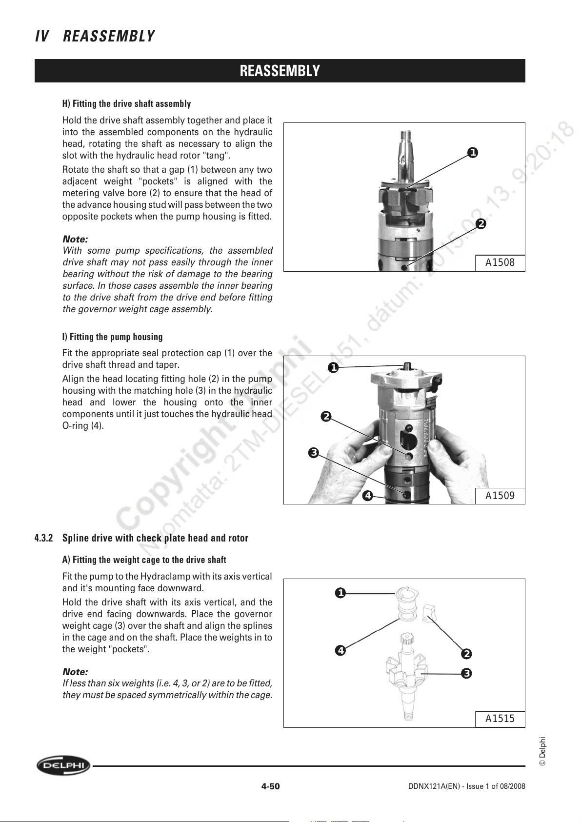
IV REASSEMBLY
H) Fitting the drive shaft assembly
Hold the drive shaft assembly together and place it
into the assembled components on the hydraulic
head, rotating the shaft as necessary to align the
slot with the hydraulic head rotor "tang".
Rotate the shaft so that a gap (1) between any two
adjacent weight "pockets" is aligned with the
metering valve bore (2) to ensure that the head of
the advance housing stud will pass between the two
opposite pockets when the pump housing is fitted.
Note:
With some pump specifications, the assembled
drive shaft may not pass easily through the inner
bearing without the risk of damage to the bearing
surface. In those cases assemble the inner bearing
to the drive shaft from the drive end before fitting
the governor weight cage assembly.
REASSEMBLY
1
2
A1508
I) Fitting the pump housing
Fit the appropriate seal protection cap (1) over the
drive shaft thread and taper.
Align the head locating fitting hole (2) in the pump
housing with the matching hole (3) in the hydraulic
head and lower the housing onto the inner
components until it just touches the hydraulic head
O-ring (4).
4.3.2 Spline drive with check plate head and rotor
A) Fitting the weight cage to the drive shaft
Fit the pump to the Hydraclamp with its axis vertical
and it's mounting face downward.
Hold the drive shaft with its axis vertical, and the
drive end facing downwards. Place the governor
weight cage (3) over the shaft and align the splines
in the cage and on the shaft. Place the weights in to
the weight "pockets".
1
2
3
4
1
4
A1509
2
Note:
If less than six weights (i.e. 4, 3, or 2) are to be fitted,
they must be spaced symmetrically within the cage.
4-50
3
A1515
© Delphi
DDNX121A(EN) - Issue 1 of 08/2008
Page 65

REASSEMBLY IV
REASSEMBLY
B) Assembling the weight cage components
Place the governor thrust washer (4) on to the "toes" (2) of the weights, followed by the thrust sleeve (1).
C) Fitting the drive shaft assembly
Place the specified seal protection cap over the drive shaft thread.
Lower the drive shaft assembly into the pump housing and carefully push it fully downwards.
D) Fitting the timing circlip (if specified)
Fit the circlip into the pump housing making sure it
locates against the shoulder in the housing with the
ears placed centrally in the housing inspection
cover aperture.
Note:
One ear of the circlip is flat, the other rounded. The
flat ear is to be positioned so that when the pump
drive shaft rotates, the drive plate timing letters turn
'towards' the flat ear and not away from it.
A1781
E) Fitting the cam ring
Fit the cam ring to the housing, with its arrow facing in the direction indicated on the pump nameplate and with
the cam advance screw hole visible through the advance device mounting face "window".
F) Fitting the hydraulic head
Realign the Hydraclamp to place the pump axis
horizontal.
Fit the hydraulic head to the housing, align the drive
shaft and drive plate "master" splines and, using a
twisting action, push the hydraulic head fully into
the housing. Align the head locking screw hole (2)
in the hydraulic head with the hole (1) in the pump
housing.
1
A1495
4.4 Securing The Hydraulic Head And Checking Drive Shaft End Float And Radial Play
4.4.1 Replacing the drive shaft seal/s
Fit the protection sleeve over the tapered end of the drive shaft. The sleeve must cover the circlip groove in the
drive shaft. Failure to do so will cause the lip of the seal to be cut and create a fuel oil leak.
Moisten a new seal with clean test oil and fit into the pump housing. Ensure that the seal is the correct way round
as noted during dismantling. Use the punch and a soft-headed mallet to drive the seal fully into the recess in the
pump housing.
© Delphi
DDNX121A(EN) - Issue 1 of 08/2008
4-51
Page 66
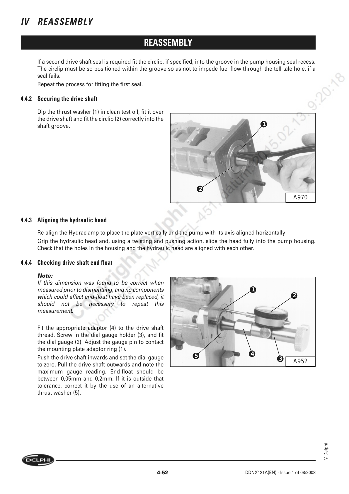
IV REASSEMBLY
REASSEMBLY
If a second drive shaft seal is required fit the circlip, if specified, into the groove in the pump housing seal recess.
The circlip must be so positioned within the groove so as not to impede fuel flow through the tell tale hole, if a
seal fails.
Repeat the process for fitting the first seal.
4.4.2 Securing the drive shaft
Dip the thrust washer (1) in clean test oil, fit it over
the drive shaft and fit the circlip (2) correctly into the
shaft groove.
2
1
A970
4.4.3 Aligning the hydraulic head
Re-align the Hydraclamp to place the plate vertically and the pump with its axis aligned horizontally.
Grip the hydraulic head and, using a twisting and pushing action, slide the head fully into the pump housing.
Check that the holes in the housing and the hydraulic head are aligned with each other.
4.4.4 Checking drive shaft end float
Note:
If this dimension was found to be correct when
measured prior to dismantling, and no components
which could affect end-float have been replaced, it
should not be necessary to repeat this
measurement.
Fit the appropriate adaptor (4) to the drive shaft
thread. Screw in the dial gauge holder (3), and fit
the dial gauge (2). Adjust the gauge pin to contact
the mounting plate adaptor ring (1).
Push the drive shaft inwards and set the dial gauge
to zero. Pull the drive shaft outwards and note the
maximum gauge reading. End-float should be
between 0,05mm and 0,2mm. If it is outside that
tolerance, correct it by the use of an alternative
thrust washer (5).
5
1
4
2
3
A952
4-52
© Delphi
DDNX121A(EN) - Issue 1 of 08/2008
Page 67
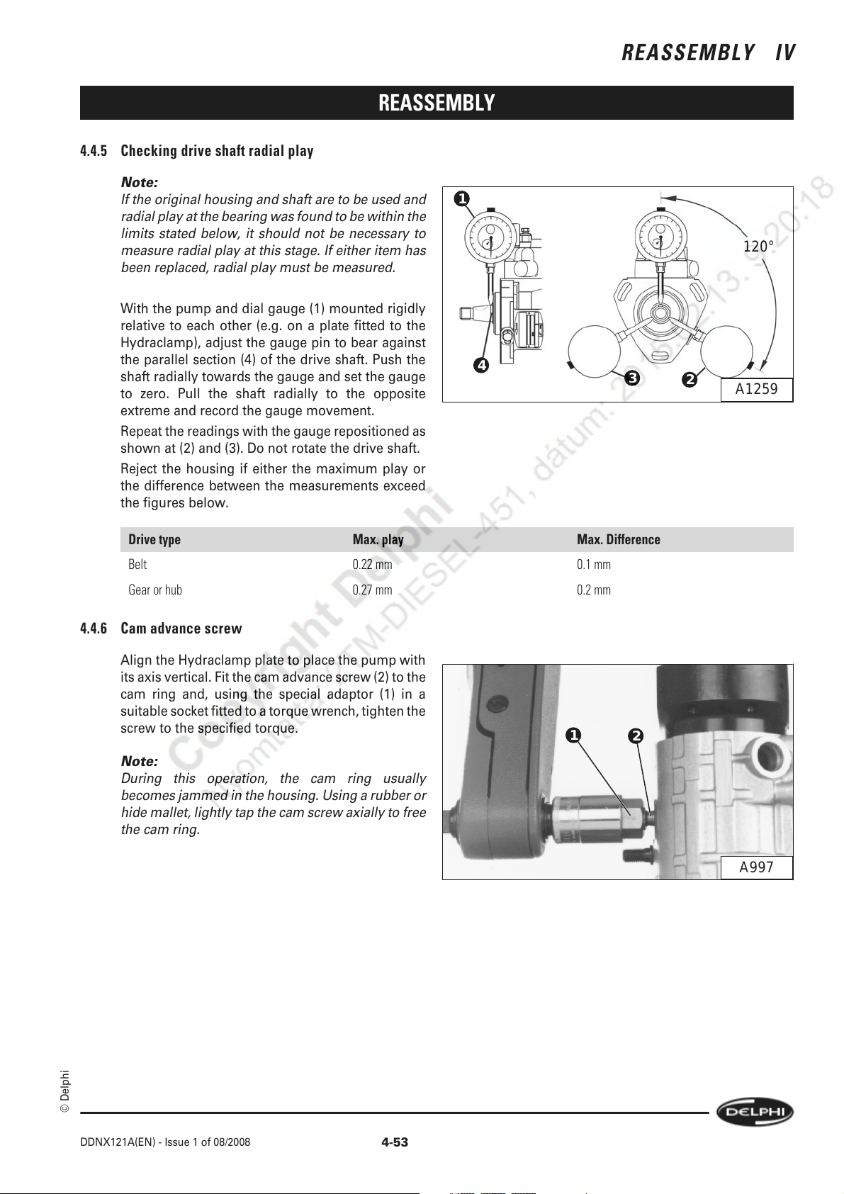
4.4.5 Checking drive shaft radial play
Note:
If the original housing and shaft are to be used and
radial play at the bearing was found to be within the
limits stated below, it should not be necessary to
measure radial play at this stage. If either item has
been replaced, radial play must be measured.
With the pump and dial gauge (1) mounted rigidly
relative to each other (e.g. on a plate fitted to the
Hydraclamp), adjust the gauge pin to bear against
the parallel section (4) of the drive shaft. Push the
shaft radially towards the gauge and set the gauge
to zero. Pull the shaft radially to the opposite
extreme and record the gauge movement.
Repeat the readings with the gauge repositioned as
shown at (2) and (3). Do not rotate the drive shaft.
Reject the housing if either the maximum play or
the difference between the measurements exceed
the figures below.
REASSEMBLY
1
4
REASSEMBLY IV
120°
3
2
A1259
Drive type Max. play Max. Difference
Belt 0.22 mm 0.1 mm
Gear or hub 0.27 mm 0.2 mm
4.4.6 Cam advance screw
Align the Hydraclamp plate to place the pump with
its axis vertical. Fit the cam advance screw (2) to the
cam ring and, using the special adaptor (1) in a
suitable socket fitted to a torque wrench, tighten the
screw to the specified torque.
Note:
During this operation, the cam ring usually
becomes jammed in the housing. Using a rubber or
hide mallet, lightly tap the cam screw axially to free
the cam ring.
1
2
A997
© Delphi
DDNX121A(EN) - Issue 1 of 08/2008
4-53
Page 68
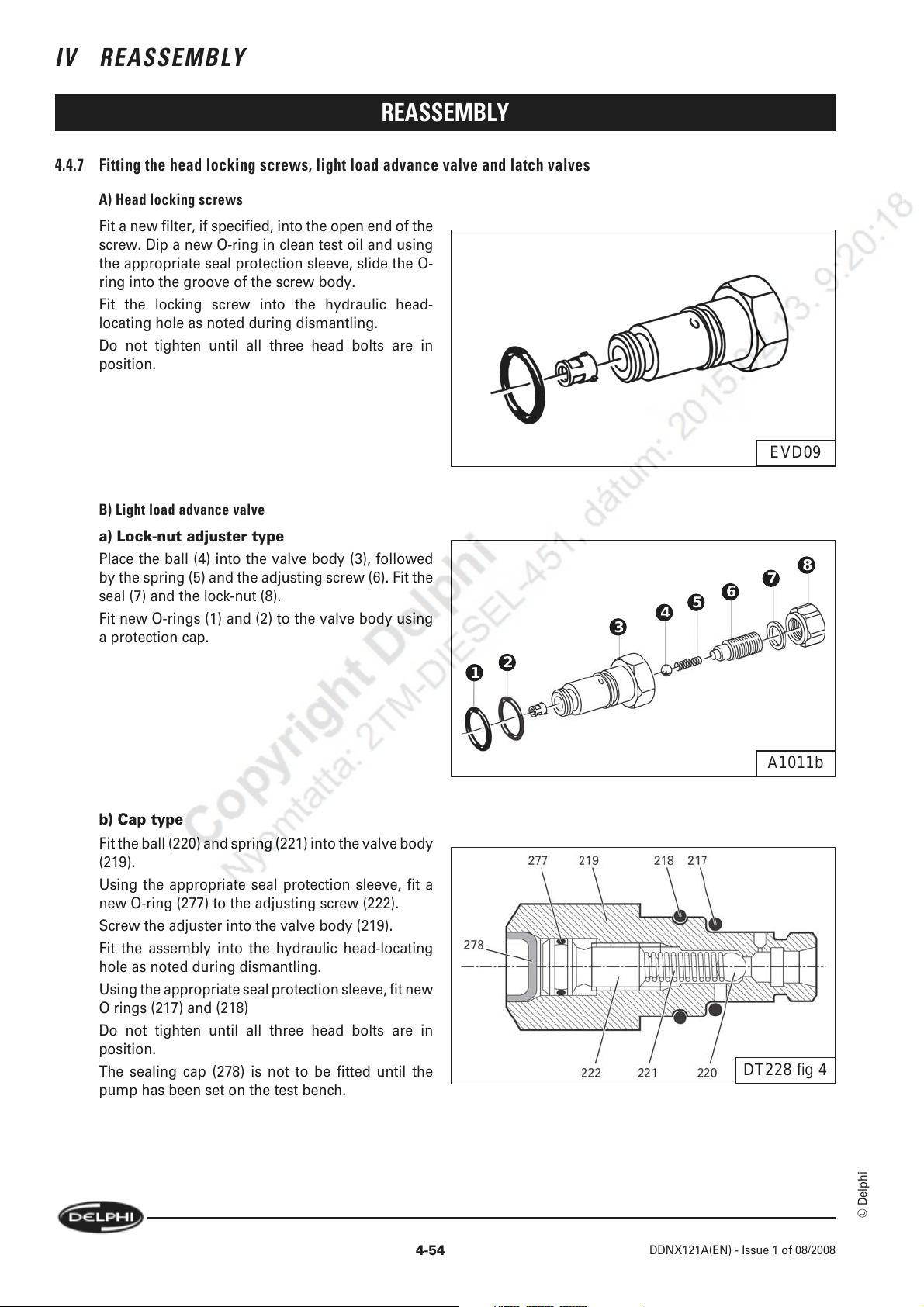
IV REASSEMBLY
REASSEMBLY
4.4.7 Fitting the head locking screws, light load advance valve and latch valves
A) Head locking screws
Fit a new filter, if specified, into the open end of the
screw. Dip a new O-ring in clean test oil and using
the appropriate seal protection sleeve, slide the O-
ring into the groove of the screw body.
Fit the locking screw into the hydraulic head-
locating hole as noted during dismantling.
Do not tighten until all three head bolts are in
position.
B) Light load advance valve
a) Lock-nut adjuster type
Place the ball (4) into the valve body (3), followed
by the spring (5) and the adjusting screw (6). Fit the
seal (7) and the lock-nut (8).
Fit new O-rings (1) and (2) to the valve body using
a protection cap.
2
1
EVD09
8
7
6
5
3
4
b) Cap type
Fit the ball (220) and spring (221) into the valve body
(219).
Using the appropriate seal protection sleeve, fit a
new O-ring (277) to the adjusting screw (222).
Screw the adjuster into the valve body (219).
Fit the assembly into the hydraulic head-locating
hole as noted during dismantling.
Using the appropriate seal protection sleeve, fit new
O rings (217) and (218)
Do not tighten until all three head bolts are in
position.
The sealing cap (278) is not to be fitted until the
pump has been set on the test bench.
A1011b
DT228 fig 4
© Delphi
4-54
DDNX121A(EN) - Issue 1 of 08/2008
Page 69

REASSEMBLY
C) Latch valve
a) Lock nut adjuster type
Fit new O-rings (9) and (10) to the valve body (8),
and fit a new O-ring (5) to the adjuster body (4),
using the appropriate seal protection sleeves. Fit
the valve (7) into the body, followed by the spring
(6); fit the adjuster (4) into the body.
Fit the adjusting screw (1) into the adjuster (4),
screwing it in by approximately four turns. Fit a new
seal (3) to the screw, followed by the lock-nut (2).
Fit a new seal (11) to the latch valve assembly; fit
the assembly through the pump housing and into
the hydraulic head.
The positions of the adjusting screw and adjuster
will be set during testing.
b) Cap type
Using the appropriate seal protection sleeve, fit new
O-rings to the valve body.
Fit the valve (1) into the body followed by the spring
(2).
Fit a new O-ring (3) using the appropriate seal
protection sleeve onto the cap (4) and screw it into
the valve body.
Fit the assembly into the hydraulic head-locating
hole as noted during dismantling.
Do not tighten until all three head bolts are in
position.
REASSEMBLY IV
4 3 2 1
10
11
987654321
A1518
DT228 fig 3
4.5 Advance Device
DP200 uses a number of different advance devices. They will fall into two main categories:
a.
Single piston design
Direct actuation of the cam-ring by an advance piston operated by transfer pressure and controlled by a
combination of spring and cambox pressure.
b.
Servo piston design
Indirect actuation of the cam-ring by an advance piston via a servo valve operated by transfer pressure and
controlled by a combination of spring and cambox pressure.
Each of these two types may be fitted with cold start timing retard with or without a wax motor mechanism.
© Delphi
DDNX121A(EN) - Issue 1 of 08/2008
4-55
Page 70
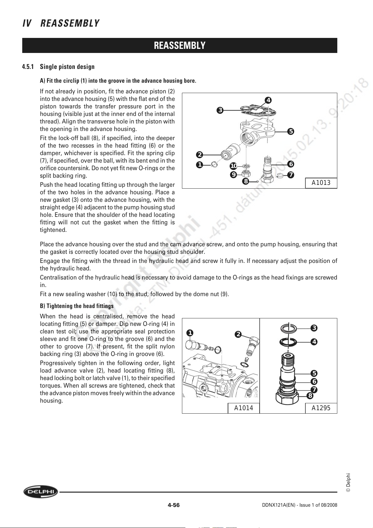
IV REASSEMBLY
REASSEMBLY
4.5.1 Single piston design
A) Fit the circlip (1) into the groove in the advance housing bore.
If not already in position, fit the advance piston (2)
into the advance housing (5) with the flat end of the
piston towards the transfer pressure port in the
housing (visible just at the inner end of the internal
thread). Align the transverse hole in the piston with
the opening in the advance housing.
Fit the lock-off ball (8), if specified, into the deeper
of the two recesses in the head fitting (6) or the
damper, whichever is specified. Fit the spring clip
(7), if specified, over the ball, with its bent end in the
orifice countersink. Do not yet fit new O-rings or the
split backing ring.
Push the head locating fitting up through the larger
of the two holes in the advance housing. Place a
new gasket (3) onto the advance housing, with the
straight edge (4) adjacent to the pump housing stud
hole. Ensure that the shoulder of the head locating
fitting will not cut the gasket when the fitting is
tightened.
4
3
5
2
1
10
9
8
6
7
A1013
Place the advance housing over the stud and the cam advance screw, and onto the pump housing, ensuring that
the gasket is correctly located over the housing stud shoulder.
Engage the fitting with the thread in the hydraulic head and screw it fully in. If necessary adjust the position of
the hydraulic head.
Centralisation of the hydraulic head is necessary to avoid damage to the O-rings as the head fixings are screwed
in.
Fit a new sealing washer (10) to the stud, followed by the dome nut (9).
B) Tightening the head fittings
When the head is centralised, remove the head
locating fitting (5) or damper. Dip new O-ring (4) in
clean test oil; use the appropriate seal protection
sleeve and fit one O-ring to the groove (6) and the
other to groove (7). If present, fit the split nylon
1
2
3
4
backing ring (3) above the O-ring in groove (6).
Progressively tighten in the following order, light
load advance valve (2), head locating fitting (8),
head locking bolt or latch valve (1), to their specified
torques. When all screws are tightened, check that
the advance piston moves freely within the advance
5
6
7
8
housing.
A1295A1014
4-56
© Delphi
DDNX121A(EN) - Issue 1 of 08/2008
Page 71

REASSEMBLY
C) Fitting the Pressure end cap
Using the appropriate seal protection cap, dip a new
O-ring (1) in clean test oil and fit it to the end plug
(2), fit the plug to the end of the advance housing at
which the transfer pressure port is visible and
tighten it to the specified torque.
D) Fitting the Spring end cap
Fit the retard spring (9) (if specified), followed by the
spring plate (8) with its spigot facing towards the
advance piston.
Note:
1 The spring plate must be fitted even if no start
retard spring is specified.
Note:
2 It is possible to confuse the start retard spring with
the spring which holds the transfer pressure
regulating sleeve in position in the end plate.
Carefully check the springs before fitment, having
identified them during dismantling, as advised.
REASSEMBLY IV
2
1
A1015
9
8
7
6
5
4
3
2
1
A1016
© Delphi
Using the appropriate seal protection cap fit the O-
ring (4) to the spring cap (3). Place the specified
number of shims (5) in the cap, followed by the
advance spring(s) (6) and (7). Screw the cap
assembly into the advance housing and tighten it to
the specified torque. Fit the cap plug (1) with a new
washer (2) and assemble it to the cap, tighten the
plug to the specified torque.
DDNX121A(EN) - Issue 1 of 08/2008
4-57
Page 72
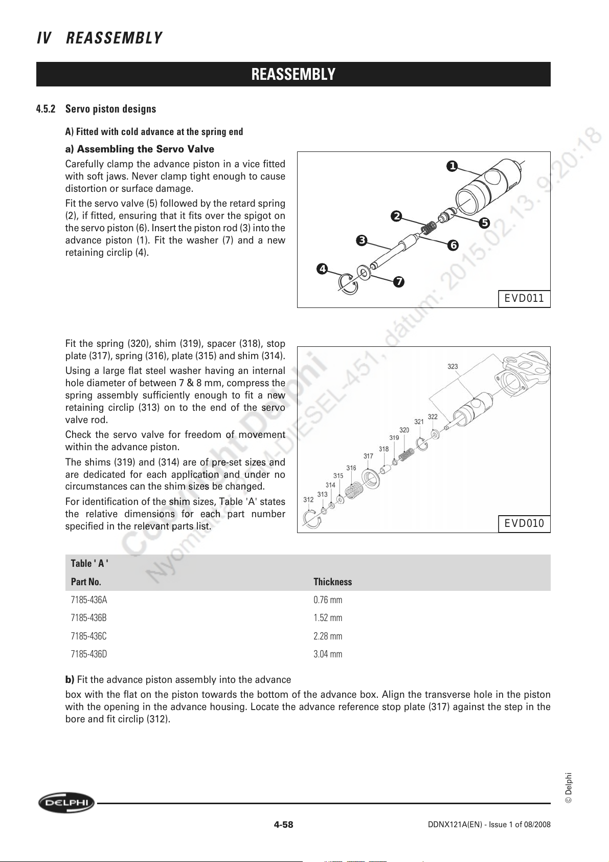
IV REASSEMBLY
4.5.2 Servo piston designs
A) Fitted with cold advance at the spring end
a) Assembling the Servo Valve
Carefully clamp the advance piston in a vice fitted
with soft jaws. Never clamp tight enough to cause
distortion or surface damage.
Fit the servo valve (5) followed by the retard spring
(2), if fitted, ensuring that it fits over the spigot on
the servo piston (6). Insert the piston rod (3) into the
advance piston (1). Fit the washer (7) and a new
retaining circlip (4).
REASSEMBLY
4
1
2
3
7
6
5
EVD011
Fit the spring (320), shim (319), spacer (318), stop
plate (317), spring (316), plate (315) and shim (314).
Using a large flat steel washer having an internal
hole diameter of between 7 & 8 mm, compress the
spring assembly sufficiently enough to fit a new
retaining circlip (313) on to the end of the servo
valve rod.
Check the servo valve for freedom of movement
within the advance piston.
The shims (319) and (314) are of pre-set sizes and
are dedicated for each application and under no
circumstances can the shim sizes be changed.
For identification of the shim sizes, Table 'A' states
the relative dimensions for each part number
specified in the relevant parts list.
Table ' A '
Part No. Thickness
7185-436A 0.76 mm
7185-436B 1.52 mm
7185-436C 2.28 mm
EVD010
7185-436D 3.04 mm
b) Fit the advance piston assembly into the advance
box with the flat on the piston towards the bottom of the advance box. Align the transverse hole in the piston
with the opening in the advance housing. Locate the advance reference stop plate (317) against the step in the
bore and fit circlip (312).
4-58
DDNX121A(EN) - Issue 1 of 08/2008
© Delphi
Page 73

REASSEMBLY IV
REASSEMBLY
c) Fitting the advance device assembly to the
pump housing
Fit the lock-off ball, if specified, into the deeper of
3
the two recesses in the head fitting (4). Do not yet
fit new O-rings.
Push the head locating fitting up through the larger
of the two holes in the advance housing. Place a
new gasket (1) onto the advance housing, with the
straight edge (2) adjacent to the pump housing stud
hole. Ensure that the shoulder of the head locating
fitting will not cut the gasket when the fitting is
tightened.
2
1
10
9
8
Place the advance housing over the stud and the
cam advance screw, and onto the pump housing,
ensuring that the gasket is correctly located over the
housing stud shoulder.
Engage the fitting with the thread in the hydraulic head and screw it fully in. If necessary adjust the position of
the hydraulic head.
Centralisation of the hydraulic head is necessary to avoid damage to the O-rings as the head fixings are screwed
in.
Fit a new sealing washer (6) to the stud, followed by the dome nut (5).
d) Tightening the head fixings
When the head is centralised, remove the head
locating fitting (5) or damper. Dip new O-ring (4) in
1
2
clean test oil; use the appropriate seal protection
sleeve and fit one O-ring to the groove (6) and the
other to groove (7). Fit the split nylon backing ring
(3) above the O-ring in groove (6).
Progressively tighten in the following order, LLA
valve (2), head locating fitting (3), head locking bolt
or latch valve (1) to their specified torques. When all
screws are tightened, check that the advance piston
moves freely within the advance housing.
4
5
6
7
A1013
3
4
5
6
7
8
A1295A1014
B) Fitted with cold advance at the pressure end
a) Assembling the Servo Valve
Fit the servo piston into the bore of the advance piston, followed by the spring piston.
Both items are symmetrical, but can be identified from each other as the servo piston is the shorter of the two
items.
© Delphi
DDNX121A(EN) - Issue 1 of 08/2008
4-59
Page 74
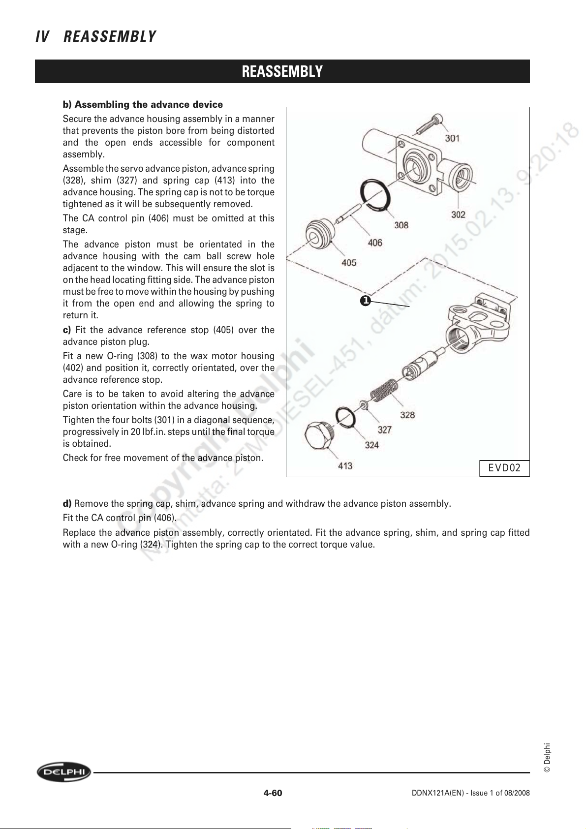
IV REASSEMBLY
b) Assembling the advance device
Secure the advance housing assembly in a manner
that prevents the piston bore from being distorted
and the open ends accessible for component
assembly.
Assemble the servo advance piston, advance spring
(328), shim (327) and spring cap (413) into the
advance housing. The spring cap is not to be torque
tightened as it will be subsequently removed.
The CA control pin (406) must be omitted at this
stage.
The advance piston must be orientated in the
advance housing with the cam ball screw hole
adjacent to the window. This will ensure the slot is
on the head locating fitting side. The advance piston
must be free to move within the housing by pushing
it from the open end and allowing the spring to
return it.
c) Fit the advance reference stop (405) over the
advance piston plug.
Fit a new O-ring (308) to the wax motor housing
(402) and position it, correctly orientated, over the
advance reference stop.
Care is to be taken to avoid altering the advance
piston orientation within the advance housing.
Tighten the four bolts (301) in a diagonal sequence,
progressively in 20 lbf.in. steps until the final torque
is obtained.
Check for free movement of the advance piston.
REASSEMBLY
1
EVD02
d) Remove the spring cap, shim, advance spring and withdraw the advance piston assembly.
Fit the CA control pin (406).
Replace the advance piston assembly, correctly orientated. Fit the advance spring, shim, and spring cap fitted
with a new O-ring (324). Tighten the spring cap to the correct torque value.
© Delphi
4-60
DDNX121A(EN) - Issue 1 of 08/2008
Page 75
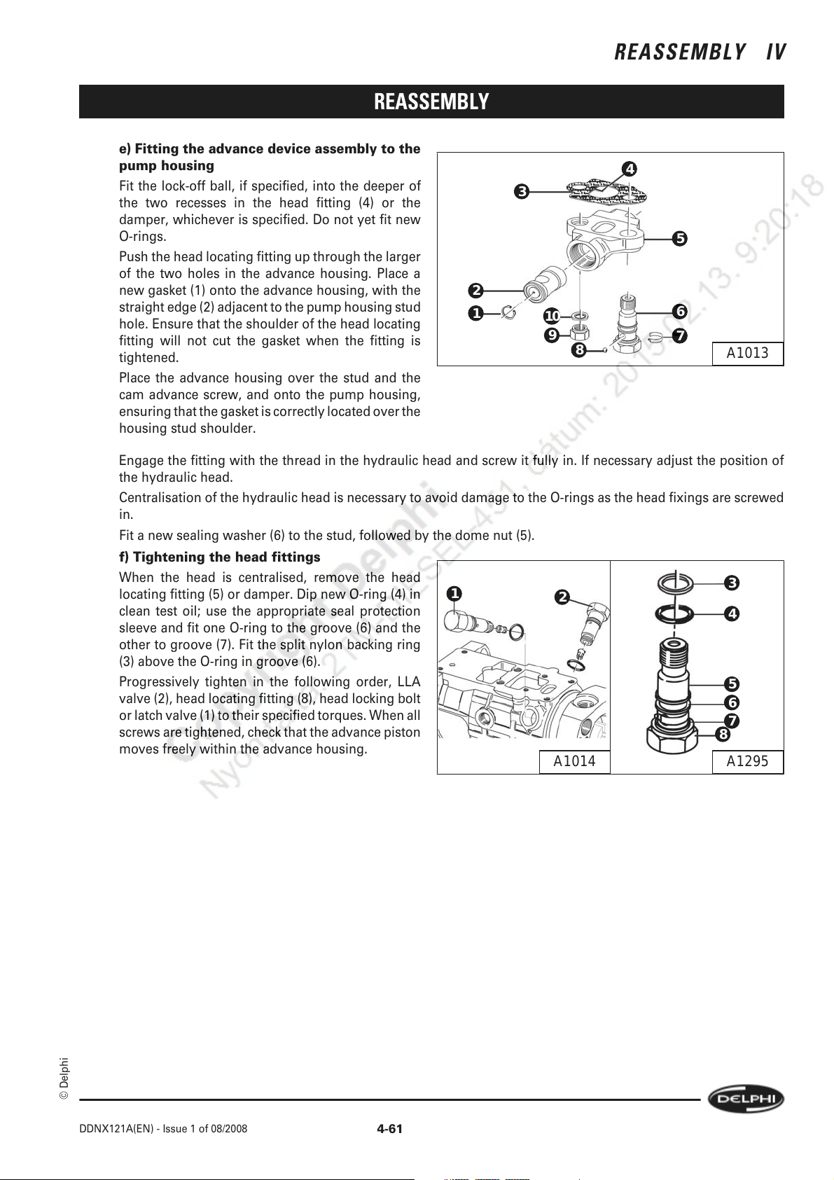
REASSEMBLY IV
REASSEMBLY
e) Fitting the advance device assembly to the
pump housing
Fit the lock-off ball, if specified, into the deeper of
3
the two recesses in the head fitting (4) or the
damper, whichever is specified. Do not yet fit new
O-rings.
Push the head locating fitting up through the larger
of the two holes in the advance housing. Place a
new gasket (1) onto the advance housing, with the
straight edge (2) adjacent to the pump housing stud
hole. Ensure that the shoulder of the head locating
fitting will not cut the gasket when the fitting is
tightened.
2
1
10
9
8
Place the advance housing over the stud and the
cam advance screw, and onto the pump housing,
ensuring that the gasket is correctly located over the
housing stud shoulder.
Engage the fitting with the thread in the hydraulic head and screw it fully in. If necessary adjust the position of
the hydraulic head.
Centralisation of the hydraulic head is necessary to avoid damage to the O-rings as the head fixings are screwed
in.
Fit a new sealing washer (6) to the stud, followed by the dome nut (5).
f) Tightening the head fittings
When the head is centralised, remove the head
locating fitting (5) or damper. Dip new O-ring (4) in
1
2
clean test oil; use the appropriate seal protection
sleeve and fit one O-ring to the groove (6) and the
other to groove (7). Fit the split nylon backing ring
(3) above the O-ring in groove (6).
Progressively tighten in the following order, LLA
valve (2), head locating fitting (8), head locking bolt
or latch valve (1) to their specified torques. When all
screws are tightened, check that the advance piston
moves freely within the advance housing.
4
5
6
7
A1013
3
4
5
6
7
8
A1295A1014
© Delphi
DDNX121A(EN) - Issue 1 of 08/2008
4-61
Page 76

IV REASSEMBLY
REASSEMBLY
4.5.3 2 Bolt Cold Advance fitted to single piston design
A) Assembly of the CA piston
Place the CA piston (2), with its open end
uppermost, in a vice fitted with soft jaws and grip
the piston lightly. Put the shim(s) (3), and the inner
and outer springs (4) and (5) into the piston,
followed by the stop tube (6), with its larger bore
facing upwards.
Note:
If either the CA housing or the advance housing has
been replaced (or both have been replaced), a new
stop plug (7) must be fitted.
9
8
7
6
5
4
3
2
1
Place the stop plug onto the piston with its shorter
taper facing the piston. Place the screw (9) in the
recessed end of the phase plate (8) and then put the
screw down through the spacer. Push the screw
down to compress the springs, fit it into the head of
the piston and tighten the screw to the specified
torque.
Place the piston assembly in the CA housing.
Note:
It is essential that only the specified torque is applied, and no more, to ensure that the screw remains tight in
service, but is not overstressed.
B) Fitment of the CA housing to the AA device
Dip a new O-ring (1) in clean test oil and fit it to the
groove in the CA housing (2). Fit the CA assembly
to the AA device and secure it with the two screws
(3) and (4) (without washers). Tighten the screws to
their specified torque.
1
2
A1487
4-62
3
DDNX121A(EN) - Issue 1 of 08/2008
A1485A1486
4
© Delphi
Page 77
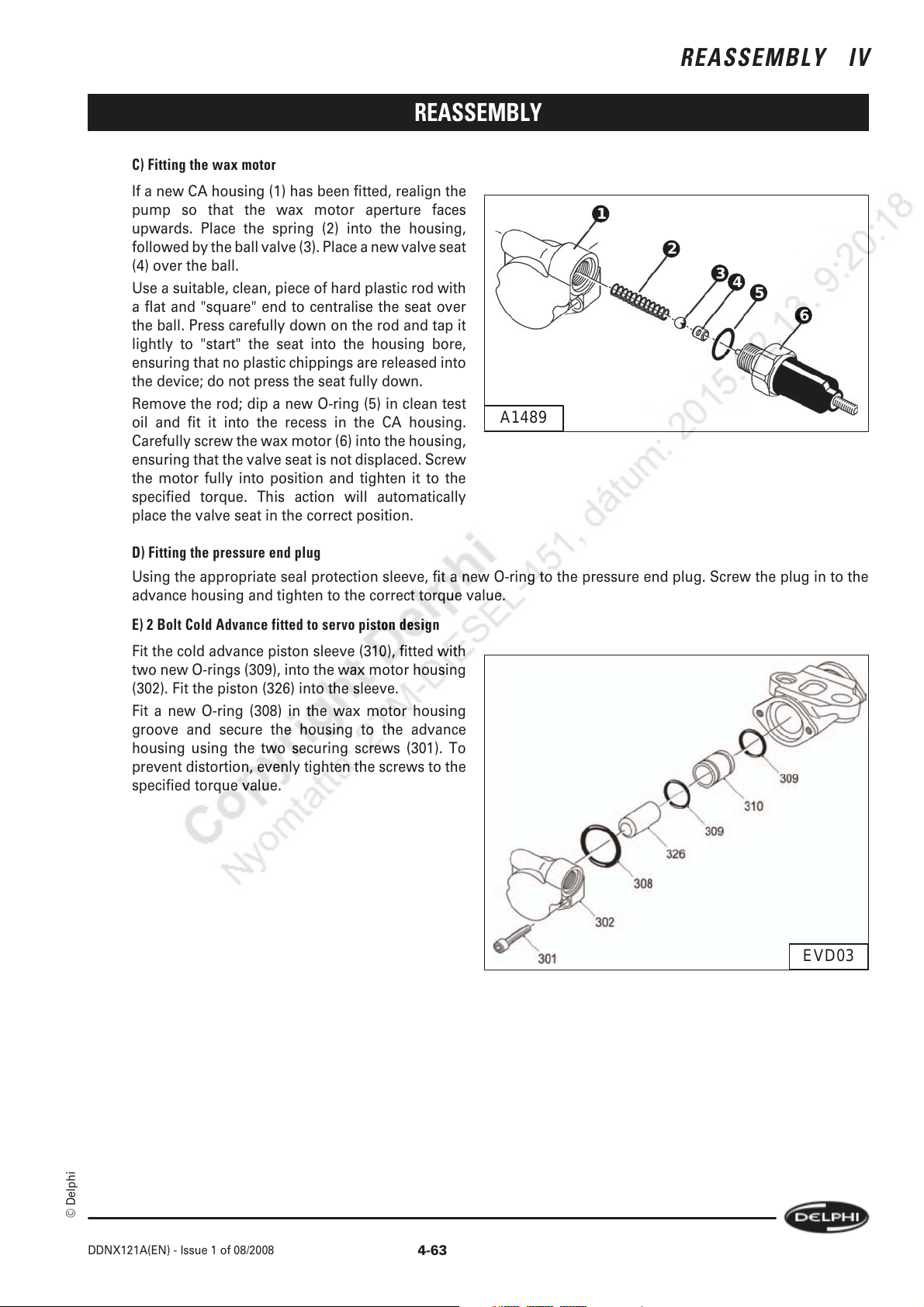
REASSEMBLY
C) Fitting the wax motor
If a new CA housing (1) has been fitted, realign the
pump so that the wax motor aperture faces
upwards. Place the spring (2) into the housing,
followed by the ball valve (3). Place a new valve seat
(4) over the ball.
Use a suitable, clean, piece of hard plastic rod with
a flat and "square" end to centralise the seat over
the ball. Press carefully down on the rod and tap it
lightly to "start" the seat into the housing bore,
ensuring that no plastic chippings are released into
the device; do not press the seat fully down.
Remove the rod; dip a new O-ring (5) in clean test
oil and fit it into the recess in the CA housing.
Carefully screw the wax motor (6) into the housing,
ensuring that the valve seat is not displaced. Screw
the motor fully into position and tighten it to the
specified torque. This action will automatically
place the valve seat in the correct position.
A1489
REASSEMBLY IV
1
2
3
4
5
6
D) Fitting the pressure end plug
Using the appropriate seal protection sleeve, fit a new O-ring to the pressure end plug. Screw the plug in to the
advance housing and tighten to the correct torque value.
E) 2 Bolt Cold Advance fitted to servo piston design
Fit the cold advance piston sleeve (310), fitted with
two new O-rings (309), into the wax motor housing
(302). Fit the piston (326) into the sleeve.
Fit a new O-ring (308) in the wax motor housing
groove and secure the housing to the advance
housing using the two securing screws (301). To
prevent distortion, evenly tighten the screws to the
specified torque value.
EVD03
© Delphi
DDNX121A(EN) - Issue 1 of 08/2008
4-63
Page 78
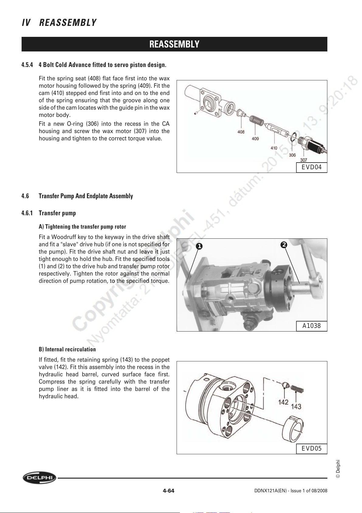
IV REASSEMBLY
REASSEMBLY
4.5.4 4 Bolt Cold Advance fitted to servo piston design.
Fit the spring seat (408) flat face first into the wax
motor housing followed by the spring (409). Fit the
cam (410) stepped end first into and on to the end
of the spring ensuring that the groove along one
side of the cam locates with the guide pin in the wax
motor body.
Fit a new O-ring (306) into the recess in the CA
housing and screw the wax motor (307) into the
housing and tighten to the correct torque value.
4.6 Transfer Pump And Endplate Assembly
EVD04
4.6.1 Transfer pump
A) Tightening the transfer pump rotor
Fit a Woodruff key to the keyway in the drive shaft
and fit a "slave" drive hub (if one is not specified for
the pump). Fit the drive shaft nut and leave it just
tight enough to hold the hub. Fit the specified tools
(1) and (2) to the drive hub and transfer pump rotor
respectively. Tighten the rotor against the normal
direction of pump rotation, to the specified torque.
B) Internal recirculation
If fitted, fit the retaining spring (143) to the poppet
valve (142). Fit this assembly into the recess in the
hydraulic head barrel, curved surface face first.
Compress the spring carefully with the transfer
pump liner as it is fitted into the barrel of the
hydraulic head.
1
2
A1038
4-64
EVD05
© Delphi
DDNX121A(EN) - Issue 1 of 08/2008
Page 79
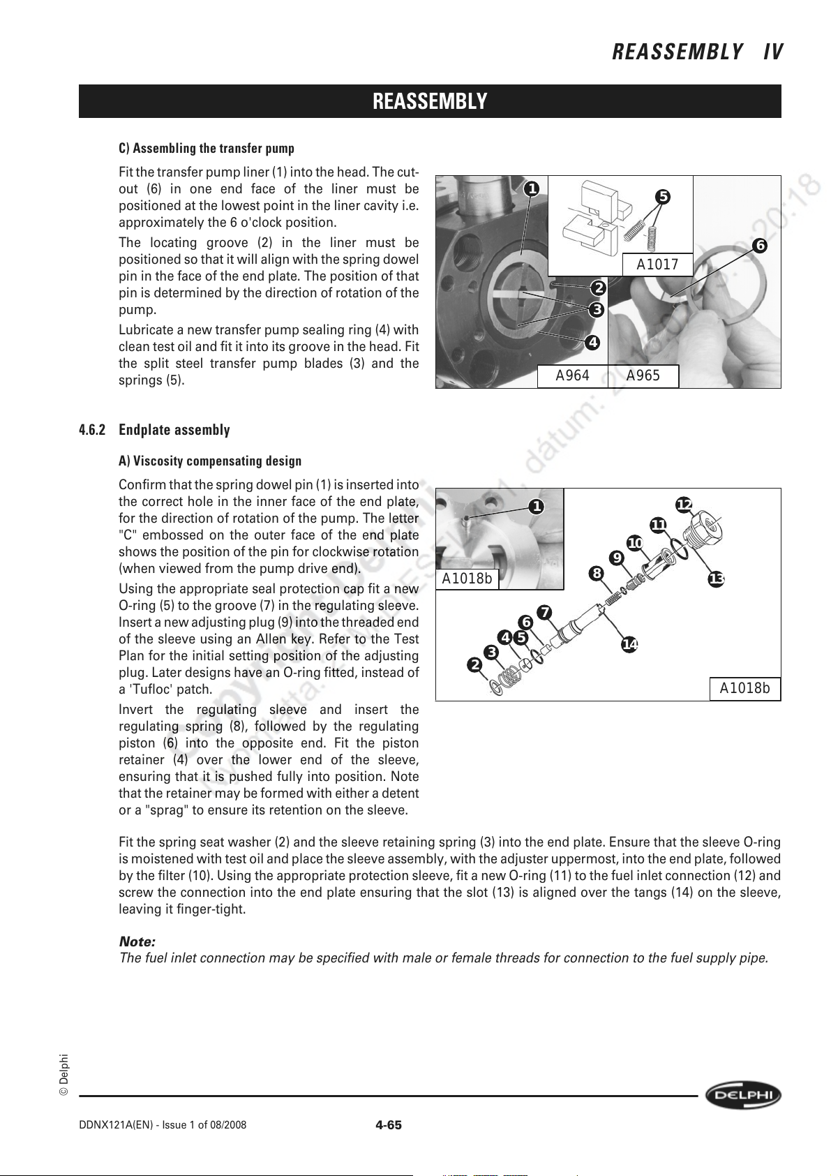
C) Assembling the transfer pump
Fit the transfer pump liner (1) into the head. The cut-
out (6) in one end face of the liner must be
positioned at the lowest point in the liner cavity i.e.
approximately the 6 o'clock position.
The locating groove (2) in the liner must be
positioned so that it wi ll align with the spring dowel
pin in the face of the end plate. The position of that
pin is determined by the direction of rotation of the
pump.
Lubricate a new transfer pump sealing ring (4) with
clean test oil and fit it into its groove in the head. Fit
the split steel transfer pump blades (3) and the
springs (5).
4.6.2 Endplate assembly
REASSEMBLY
REASSEMBLY IV
1
2
3
4
A964
5
6
A1017
A965
A) Viscosity compensating design
Confirm that the spring dowel pin (1) is inserted into
the correct hole in the inner face of the end plate,
for the direction of rotation of the pump. The letter
"C" embossed on the outer face of the end plate
shows the position of the pin for clockwise rotation
(when viewed from the pump drive end).
Using the appropriate seal protection cap fit a new
O-ring (5) to the groove (7) in the regulating sleeve.
Insert a new adjusting plug (9) into the threaded end
of the sleeve using an Allen key. Refer to the Test
Plan for the initial setting position of the adjusting
plug. Later designs have an O-ring fitted, instead of
a 'Tufloc' patch.
A1018b
2
1
10
9
8
7
6
4
5
3
14
12
11
13
A1018b
Invert the regulating sleeve and insert the
regulating spring (8), followed by the regulating
piston (6) into the opposite end. Fit the piston
retainer (4) over the lower end of the sleeve,
ensuring that it is pushed fully into position. Note
that the retainer may be formed with either a detent
or a "sprag" to ensure its retention on the sleeve.
Fit the spring seat washer (2) and the sleeve retaining spring (3) into the end plate. Ensure that the sleeve O-ring
is moistened with test oil and place the sleeve assembly, with the adjuster uppermost, into the end plate, followed
by the filter (10). Using the appropriate protection sleeve, fit a new O-ring (11) to the fuel inlet connection (12) and
screw the connection into the end plate ensuring that the slot (13) is aligned over the tangs (14) on the sleeve,
leaving it finger-tight.
Note:
The fuel inlet connection may be specified with male or female threads for connection to the fuel supply pipe.
© Delphi
DDNX121A(EN) - Issue 1 of 08/2008
4-65
Page 80

IV REASSEMBLY
B) Non-viscosity compensating design
Insert the priming spring (288) into the bottom of
the end plate housing (150) ensuring the spring
remains correctly positioned and does not turn on
to its side. Fit a new sealing washer (248) to the
regulating sleeve (245) and insert the regulating
piston (287) into the sleeve. Place the sleeve and
piston into the end plate with the sleeve priming
port at the bottom.
Place a new filter (242) with its flange uppermost,
into the endplate and push it gently and firmly down
until squarely seated on the top of the sleeve.
Fit the regulating spring and peg (286) into the
sleeve, followed by the adjuster assembly (285)
with the screw adjuster socket head upper most and
the retaining spring (284). Fit a new O-ring (241) to
the fuel inlet connection (240) and screw into the
endplate assembly finger tight.
REASSEMBLY
A493b
C) Sandwich plate
Fit the sandwich plate (1) into the recess in the
endplate (2), with either face outwards if new, but
with the same face towards the transfer rotor if the
original plate is to be used again. The spring dowel
pin will control the position of the groove in the
edge of the plate.
Note:
If the original sandwich plate shows any signs of
scoring, do not reverse it as this will cause internal
leaks and affect the efficiency of the transfer pump;
it must be replaced.
D) Fitting the endplate assembly
Fit the endplate in position, matching the slot in the
liner to the spring pin. Fasten the endplate with the
four Allen screws (2) and (3) tightened
progressively and diagonally to the specified
torque.
Tighten the fuel inlet connection (1) to the specified
torque.
Check that the drive shaft rotates freely.
1
2
A1020
1
2
4-66
3
DDNX121A(EN) - Issue 1 of 08/2008
A1305a
© Delphi
Page 81
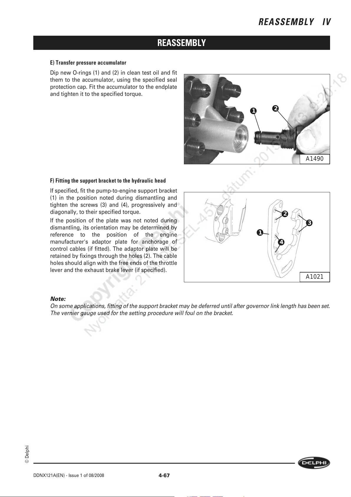
REASSEMBLY
E) Transfer pressure accumulator
Dip new O-rings (1) and (2) in clean test oil and fit
them to the accumulator, using the specified seal
protection cap. Fit the accumulator to the endplate
and tighten it to the specified torque.
REASSEMBLY IV
F) Fitting the support bracket to the hydraulic head
If specified, fit the pump-to-engine support bracket
(1) in the position noted during dismantling and
tighten the screws (3) and (4), progressively and
diagonally, to their specified torque.
If the position of the plate was not noted during
dismantling, its orientation may be determined by
reference to the position of the engine
manufacturer's adaptor plate for anchorage of
control cables (if fitted). The adaptor plate will be
retained by fixings through the holes (2). The cable
holes should align with the free ends of the throttle
lever and the exhaust brake lever (if specified).
1
2
A1490
2
3
1
4
A1021
© Delphi
Note:
On some applications, fitting of the support bracket may be deferred until after governor link length has been set.
The vernier gauge used for the setting procedure will foul on the bracket.
DDNX121A(EN) - Issue 1 of 08/2008
4-67
Page 82

IV REASSEMBLY
4.7 ESOS And High Pressure Outlets
4.7.1 ESOS or blanking plug
Note:
1 If the solenoid (1) is of the later type, the spring
(3) will be attached to the plunger (4) and is not
replaceable.
Note:
2 It is essential that the specified solenoid is fitted,
as there are versions available which operate in the
reverse sense to all others or require additional
wiring and resistors. Refer to the Despatch Number
and SIN DT294 for correct details.
REASSEMBLY
1
2
3
4
5
A1292
6
7
If detachable electrical connections are specified for
the solenoid fit the terminal blade (5) to the
solenoid, retained by the washer (7) and nut (6).
Fit a new O-ring (2) to the solenoid body (1), using the appropriate seal protection sleeve. Place the plunger return
spring (3) into the solenoid, followed by the plunger (4), with the flexible seal end outwards. Later designs have
captive plungers. Screw the assembly into the hydraulic head and leave it finger tight.
If a blanking plug is specified, dip a new O-ring in clean test oil and fit it to the plug, using the appropriate seal
protection sleeve. Screw the plug into the hydraulic head, leaving it finger-tight.
The solenoid (or plug) will be removed for fitment of a pressure gauge during testing.
4.7.2 High pressure outlets and clamp plate
Reposition the Hydraclamp to place the pump axis
vertically, with the end plate uppermost.
The outlet connections may be fitted either with
pressurising valves (4) (which are factory-sealed
units), or delivery valves (6).
1
2
3
5
7
6
A1022A1035
8
4
A1023
A) Pressurising valves
Into each high pressure outlet of the hydraulic head fit a new sealing washer (1) then fit the pressurising valve (4)
leaving it finger-tight.
4-68
DDNX121A(EN) - Issue 1 of 08/2008
© Delphi
Page 83
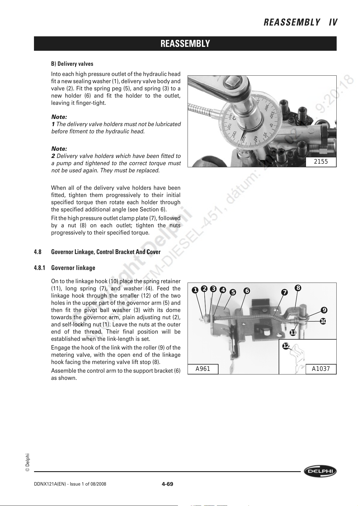
REASSEMBLY
B) Delivery valves
Into each high pressure outlet of the hydraulic head
fit a new sealing washer (1), delivery valve body and
valve (2). Fit the spring peg (5), and spring (3) to a
new holder (6) and fit the holder to the outlet,
leaving it finger-tight.
Note:
1 The delivery valve holders must not be lubricated
before fitment to the hydraulic head.
Note:
2 Delivery valve holders which have been fitted to
a pump and tightened to the correct torque must
not be used again. They must be replaced.
When all of the delivery valve holders have been
fitted, tighten them progressively to their initial
specified torque then rotate each holder through
the specified additional angle (see Section 6).
Fit the high pressure outlet clamp plate (7), followed
by a nut (8) on each outlet; tighten the nuts
progressively to their specified torque.
REASSEMBLY IV
2155
4.8 Governor Linkage, Control Bracket And Cover
4.8.1 Governor linkage
On to the linkage hook (10) place the spring retainer
(11), long spring (7), and washer (4). Feed the
linkage hook through the smaller (12) of the two
holes in the upper part of the governor arm (5) and
then fit the pivot ball washer (3) with its dome
towards the governor arm, plain adjusting nut (2),
and self-locking nut (1). Leave the nuts at the outer
end of the thread. Their final position will be
established when the link-length is set.
Engage the hook of the link with the roller (9) of the
metering valve, with the open end of the linkage
hook facing the metering valve lift stop (8).
Assemble the control arm to the support bracket (6)
as shown.
1
A961
2
3
4
6
5
7
12
8
9
10
11
A1037
© Delphi
DDNX121A(EN) - Issue 1 of 08/2008
4-69
Page 84
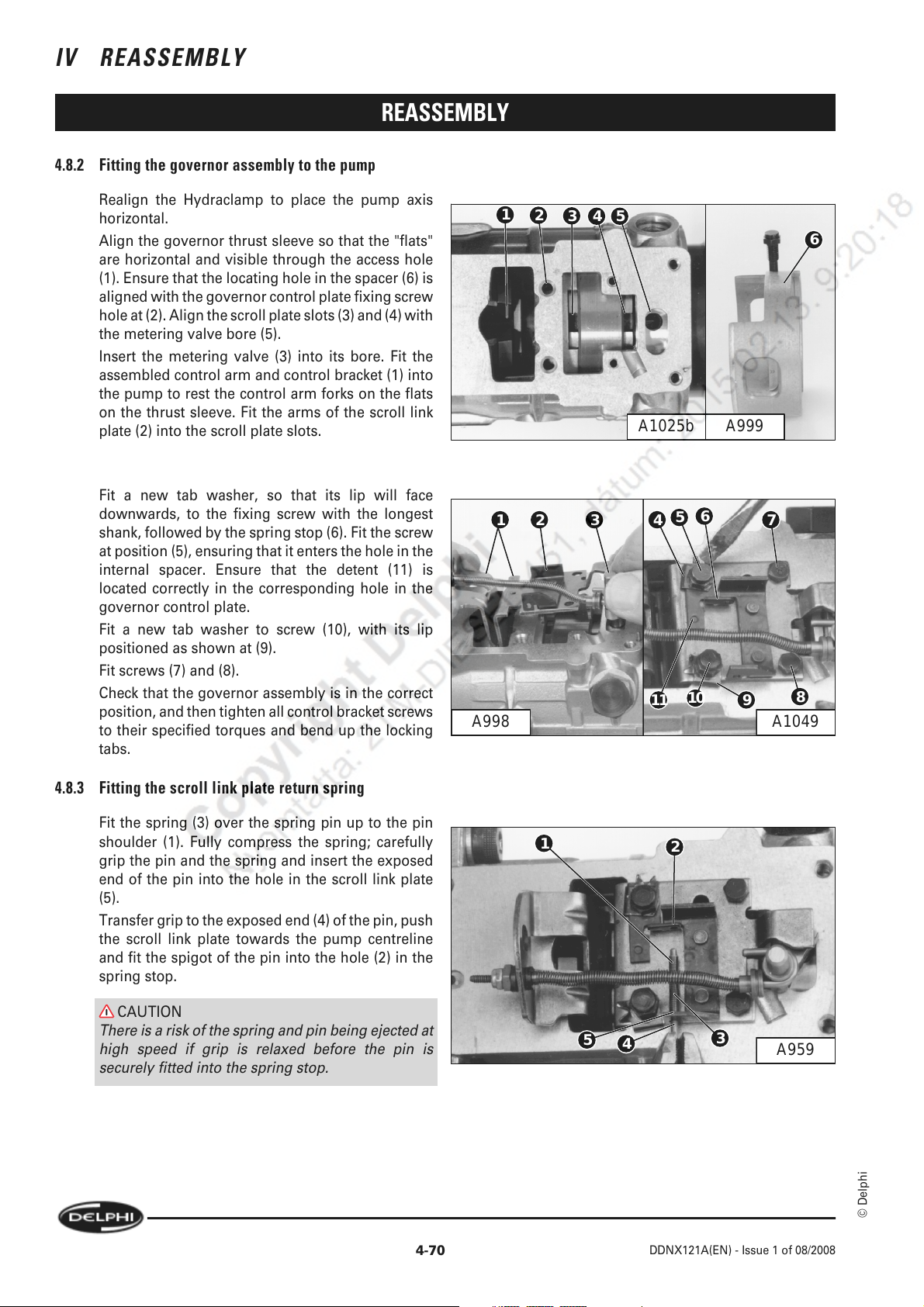
IV REASSEMBLY
4.8.2 Fitting the governor assembly to the pump
REASSEMBLY
Realign the Hydraclamp to place the pump axis
horizontal.
Align the governor thrust sleeve so that the "flats"
are horizontal and visible through the access hole
(1). Ensure that the locating hole in the spacer (6) is
aligned with the governor control plate fixing screw
hole at (2). Align the scroll plate slots (3) and (4) with
the metering valve bore (5).
Insert the metering valve (3) into its bore. Fit the
assembled control arm and control bracket (1) into
the pump to rest the control arm forks on the flats
on the thrust sleeve. Fit the arms of the scroll link
plate (2) into the scroll plate slots.
Fit a new tab washer, so that its lip will face
downwards, to the fixing screw with the longest
shank, followed by the spring stop (6). Fit the screw
at position (5), ensuring that it enters the hole in the
internal spacer. Ensure that the detent (11) is
located correctly in the corresponding hole in the
governor control plate.
Fit a new tab washer to screw (10), with its lip
positioned as shown at (9).
Fit screws (7) and (8).
Check that the governor assembly is in the correct
position, and then tighten all control bracket screws
to their specified torques and bend up the locking
tabs.
1
2
3
54
6
A999A1025b
4321
11
5
10
7
9
8
6
A1049A998
4.8.3 Fitting the scroll link plate return spring
Fit the spring (3) over the spring pin up to the pin
shoulder (1). Fully compress the spring; carefully
grip the pin and the spring and insert the exposed
end of the pin into the hole in the scroll link plate
(5).
Transfer grip to the exposed end (4) of the pin, push
the scroll link plate towards the pump centreline
and fit the spigot of the pin into the hole (2) in the
spring stop.
CAUTION
There is a risk of the spring and pin being ejected at
high speed if grip is relaxed before the pin is
securely fitted into the spring stop.
1
5
4
2
3
A959
© Delphi
4-70
DDNX121A(EN) - Issue 1 of 08/2008
Page 85
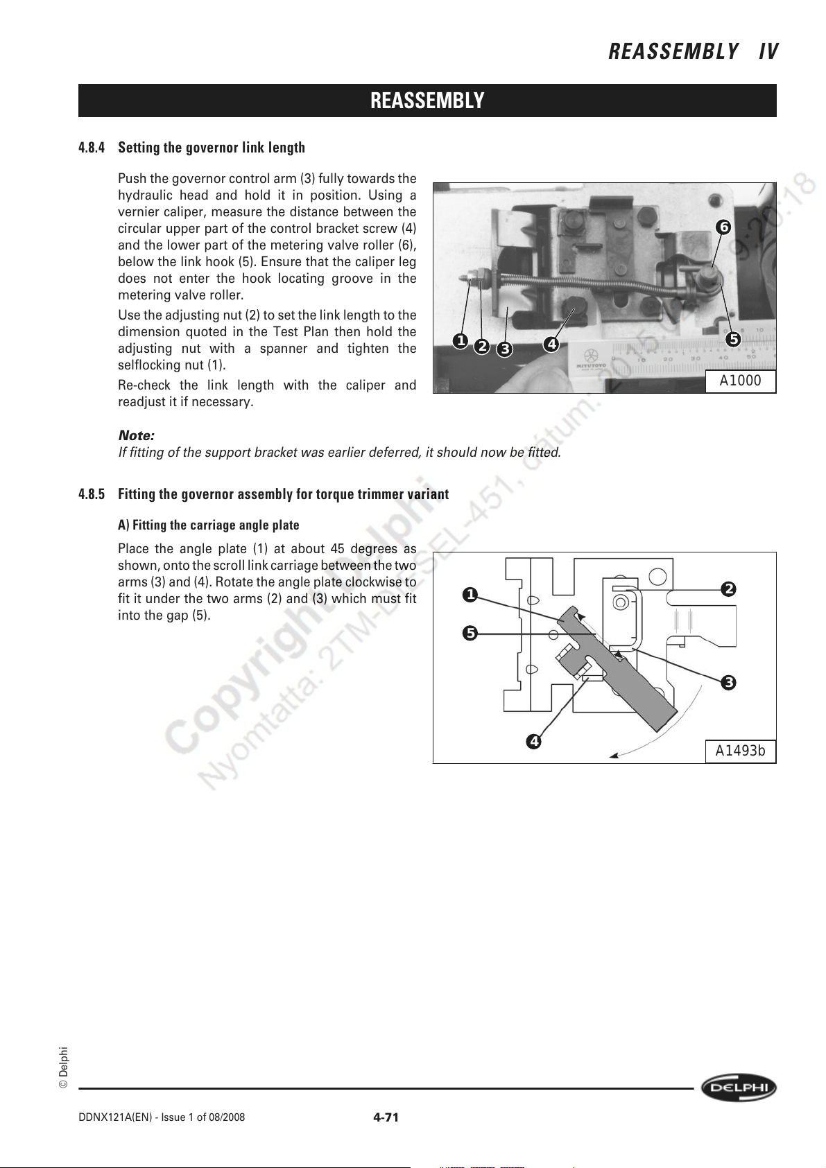
REASSEMBLY
4.8.4 Setting the governor link length
Push the governor control arm (3) fully towards the
hydraulic head and hold it in position. Using a
vernier caliper, measure the distance between the
circular upper part of the control bracket screw (4)
and the lower part of the metering valve roller (6),
below the link hook (5). Ensure that the caliper leg
does not enter the hook locating groove in the
metering valve roller.
Use the adjusting nut (2) to set the link length to the
dimension quoted in the Test Plan then hold the
adjusting nut with a spanner and tighten the
selflocking nut (1).
Re-check the link length with the caliper and
readjust it if necessary.
Note:
If fitting of the support bracket was earlier deferred, it should now be fitted.
1
2
REASSEMBLY IV
6
3
4
5
A1000
4.8.5 Fitting the governor assembly for torque trimmer variant
A) Fitting the carriage angle plate
Place the angle plate (1) at about 45 degrees as
shown, onto the scroll link carriage between the two
arms (3) and (4). Rotate the angle plate clockwise to
fit it under the two arms (2) and (3) which must fit
into the gap (5).
1
5
4
2
3
A1493b
© Delphi
DDNX121A(EN) - Issue 1 of 08/2008
4-71
Page 86
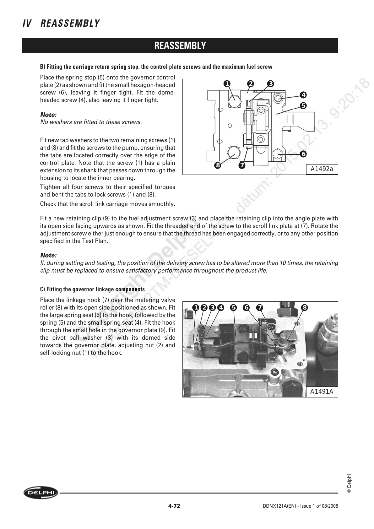
IV REASSEMBLY
REASSEMBLY
B) Fitting the carriage return spring stop, the control plate screws and the maximum fuel screw
Place the spring stop (5) onto the governor control
plate (2) as shown and fit the small hexagon-headed
screw (6), leaving it finger tight. Fit the dome-
headed screw (4), also leaving it finger tight.
Note:
No washers are fitted to these screws.
Fit new tab washers to the two remaining screws (1)
and (8) and fit the screws to the pump, ensuring that
the tabs are located correctly over the edge of the
control plate. Note that the screw (1) has a plain
extension to its shank that passes down through the
housing to locate the inner bearing.
Tighten all four screws to their specified torques
and bent the tabs to lock screws (1) and (8).
Check that the scroll link carriage moves smoothly.
321
4
5
6
78
A1492a
Fit a new retaining clip (9) to the fuel adjustment screw (3) and place the retaining clip into the angle plate with
its open side facing upwards as shown. Fit the threaded end of the screw to the scroll link plate at (7). Rotate the
adjustment screw either just enough to ensure that the thread has been engaged correctly, or to any other position
specified in the Test Plan.
Note:
If, during setting and testing, the position of the delivery screw has to be altered more than 10 times, the retaining
clip must be replaced to ensure satisfactory performance throughout the product life.
C) Fitting the governor linkage components
Place the linkage hook (7) over the metering valve
roller (8) with its open side positioned as shown. Fit
the large spring seat (6) to the hook, followed by the
spring (5) and the small spring seat (4). Fit the hook
through the small hole in the governor plate (9). Fit
the pivot ball washer (3) with its domed side
towards the governor plate, adjusting nut (2) and
self-locking nut (1) to the hook.
1 8765432
A1491A
4-72
© Delphi
DDNX121A(EN) - Issue 1 of 08/2008
Page 87

REASSEMBLY
D) Fitting the scroll link plate return spring
Grip the spring pin (1) lightly with thin-nosed pliers
and place the spring (3) over the pin, holding the
spring in position. Place the plain end of the pin in
the relevant hole in the scroll link carriage (4) and
the shouldered end in the hole (2) in the spring stop.
Release the pin.
Check again that the scroll link carriage moves
smoothly and is returned fully to its rest position by
the spring.
REASSEMBLY IV
2
1
3
E) Setting the governor link-length
Set a vernier caliper to the link-length specified in
the Test Pan. Push the scroll link carriage against
the return spring to allow one leg of the gauge to
be placed against the circular head of the control
plate screw (5). Place the other leg against the
metering valve roller (4). Ensure that the gauge leg
does not slip into the groove in which the link hook
(3) is located.
Note:
For some pump specifications it may be necessary
to remove the support plate from the hydraulic head
to allow correct use of the vernier caliper.
Adjust the nut (2) and lock nut (1) to obtain the
required dimension. Tighten the lock nut and check
that the setting has not been disturbed.
4
2
1
5
A1491
4
3
A1511
© Delphi
DDNX121A(EN) - Issue 1 of 08/2008
4-73
Page 88

IV REASSEMBLY
REASSEMBLY
4.9 Assembling The Governor Cover
4.9.1 Governor cover only
A) Exhaust brake/manual shut-off control shaft and "trapped" O-ring
Fill the grease groove (3) on the shaft with the
specified grease. Using the appropriate seal
protection cap fit two new O-rings (1) to the grooves
(2) and (4). Fit the shaft into its bore in the governor
cover, ensuring that it is pushed fully into position.
Rotate the shaft until the "upturn" on the lever is
against the flat inside face of the governor cover (6).
Fit a new large O-ring (5) to the groove in the
governor cover.
1
5
2
3
4
A1026
B) Throttle shaft and governor main spring
Fit the specified seal protection sleeve over the
throttle shaft (9); slide two new O-rings into position
at (7) and (8).
Fit the idling spring (2) and the pivot ball washer (3)
(with its spherical face towards the governor arm
(4)) to the spring guide (1). Fit the guide through the
large hole in the governor arm.
Hook one end of the governor main spring (5)
through the hole in the end of the guide and the
other end through the hole in the throttle shaft link
(6).
Note:
Early designs of throttle shafts had 3 holes. The hole
to be used will be stated in the Test Plan.
Fill the throttle shaft grease groove (10) with the
specified grease.
6
A1001
10987654321
A958
4-74
© Delphi
DDNX121A(EN) - Issue 1 of 08/2008
Page 89
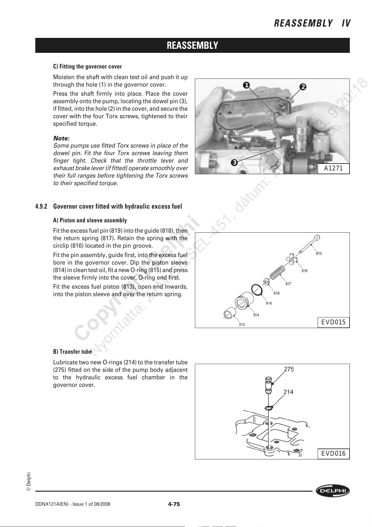
REASSEMBLY
C) Fitting the governor cover
Moisten the shaft with clean test oil and push it up
through the hole (1) in the governor cover.
Press the shaft firmly into place. Place the cover
assembly onto the pump, locating the dowel pin (3),
if fitted, into the hole (2) in the cover, and secure the
cover with the four Torx screws, tightened to their
specified torque.
Note:
Some pumps use fitted Torx screws in place of the
dowel pin. Fit the four Torx screws leaving them
finger tight. Check that the throttle lever and
exhaust brake lever (if fitted) operate smoothly over
their full ranges before tightening the Torx screws
to their specified torque.
REASSEMBLY IV
1
3
2
A1271
4.9.2 Governor cover fitted with hydraulic excess fuel
A) Piston and sleeve assembly
Fit the excess fuel pin (819) into the guide (818), then
the return spring (817). Retain the spring with the
circlip (816) located in the pin groove.
Fit the pin assembly, guide first, into the excess fuel
bore in the governor cover. Dip the piston sleeve
(814) in clean test oil, fit a new O-ring (815) and press
the sleeve firmly into the cover, O-ring end first.
Fit the excess fuel piston (813), open end inwards,
into the piston sleeve and over the return spring.
B) Transfer tube
Lubricate two new O-rings (214) to the transfer tube
(275) fitted on the side of the pump body adjacent
to the hydraulic excess fuel chamber in the
governor cover.
EVD015
© Delphi
DDNX121A(EN) - Issue 1 of 08/2008
EVD016
4-75
Page 90
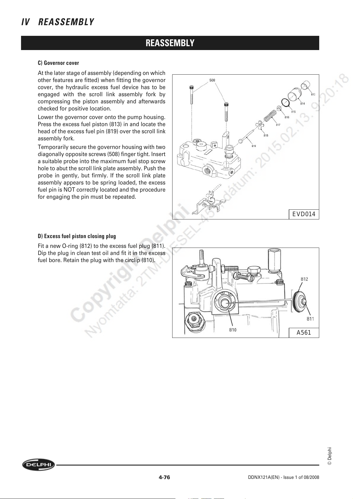
IV REASSEMBLY
C) Governor cover
At the later stage of assembly (depending on which
other features are fitted) when fitting the governor
cover, the hydraulic excess fuel device has to be
engaged with the scroll link assembly fork by
compressing the piston assembly and afterwards
checked for positive location.
Lower the governor cover onto the pump housing.
Press the excess fuel piston (813) in and locate the
head of the excess fuel pin (819) over the scroll link
assembly fork.
Temporarily secure the governor housing with two
diagonally opposite screws (508) finger tight. Insert
a suitable probe into the maximum fuel stop screw
hole to abut the scroll link plate assembly. Push the
probe in gently, but firmly. If the scroll link plate
assembly appears to be spring loaded, the excess
fuel pin is NOT correctly located and the procedure
for engaging the pin must be repeated.
REASSEMBLY
D) Excess fuel piston closing plug
Fit a new O-ring (812) to the excess fuel plug (811).
Dip the plug in clean test oil and fit it in the excess
fuel bore. Retain the plug with the circlip (810).
EVD014
A561
4-76
© Delphi
DDNX121A(EN) - Issue 1 of 08/2008
Page 91
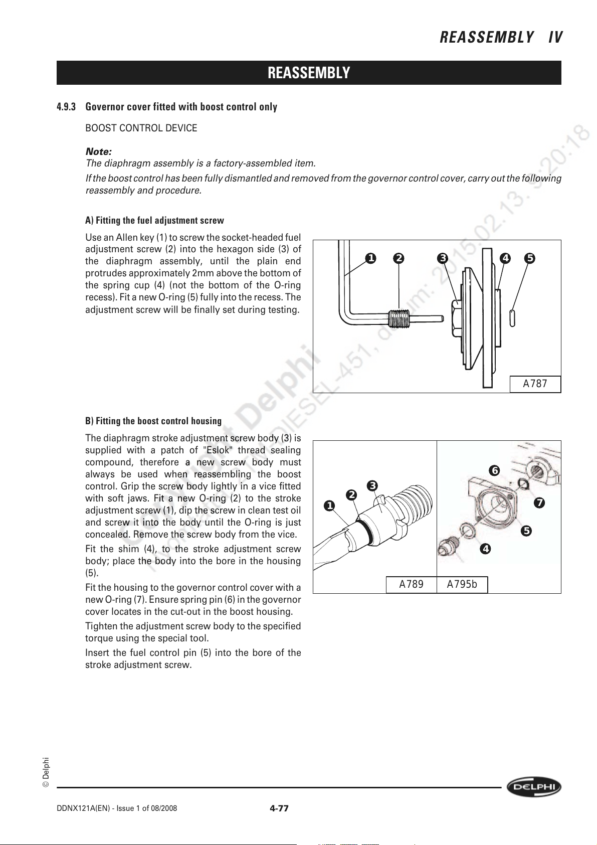
REASSEMBLY IV
REASSEMBLY
4.9.3 Governor cover fitted with boost control only
BOOST CONTROL DEVICE
Note:
The diaphragm assembly is a factory-assembled item.
If the boost control has been fully dismantled and removed from the governor control cover, carry out the following
reassembly and procedure.
A) Fitting the fuel adjustment screw
Use an Allen key (1) to screw the socket-headed fuel
adjustment screw (2) into the hexagon side (3) of
the diaphragm assembly, until the plain end
protrudes approximately 2mm above the bottom of
the spring cup (4) (not the bottom of the O-ring
recess). Fit a new O-ring (5) fully into the recess. The
adjustment screw will be finally set during testing.
2 53 41
B) Fitting the boost control housing
The diaphragm stroke adjustment screw body (3) is
supplied with a patch of "Eslok" thread sealing
compound, therefore a new screw body must
always be used when reassembling the boost
control. Grip the screw body lightly in a vice fitted
with soft jaws. Fit a new O-ring (2) to the stroke
adjustment screw (1), dip the screw in clean test oil
and screw it into the body until the O-ring is just
concealed. Remove the screw body from the vice.
Fit the shim (4), to the stroke adjustment screw
body; place the body into the bore in the housing
(5).
Fit the housing to the governor control cover with a
new O-ring (7). Ensure spring pin (6) in the governor
cover locates in the cut-out in the boost housing.
Tighten the adjustment screw body to the specified
torque using the special tool.
Insert the fuel control pin (5) into the bore of the
stroke adjustment screw.
A787
6
3
2
1
4
7
5
A795bA789
© Delphi
DDNX121A(EN) - Issue 1 of 08/2008
4-77
Page 92

IV REASSEMBLY
C) Fitting the diaphragm
Fit the specified thickness of spring shim (4) into the
boost control housing and over the stroke
adjustment screw body, followed by the spring (3).
Place the spring seat (2) into the spring cup of the
diaphragm assembly (1) and place the diaphragm
assembly over the spring, ensuring that the seat
remains in the cup.
D) Fitting the cover
Fit the cover (1) to the housing and secure it with
the two screws (2) and (3).
Note:
1 At this stage, the position of the boost pressure
inlet (1) is not important.
REASSEMBLY
1 5432
A788
1
2
Note:
2 If the boost cover is a tamper resistant version,
then the use of an old cover allowing fitment of the
setting gauge will be required until after the stroke
and/or fuel settings have been made.
E) Setting the boost stroke
a) Fitting the gauge
Fit the special tool (3) and dial gauge (2) to the cover,
locking the gauge in position with the grub screw
(4). Set the gauge to zero then fully depress the
gauge pin (1) against the diaphragm spring and
note the reading. This "boost stroke" will be
specified in the test plan.
3
A791
2
1
3
4
A796
4-78
© Delphi
DDNX121A(EN) - Issue 1 of 08/2008
Page 93

REASSEMBLY
b) Adjusting the stroke
If adjustment is required, remove the cover and dial
gauge and the inner components. Clockwise
rotation of the stroke adjustment screw (1) will
increase stroke. Replace the inner components,
cover, gauge and tool to check the stroke.
When the stroke has been set, remove the gauge
and tool from the cover and tighten the two housing
cover screws to their specified torques.
Note:
If the boost cover is a tamper resistant version, then
the use of an old cover allowing fitment of the
setting gauge will be required until after the stroke
and/or fuel settings have been made.
F) Fitting the cover plug (non-tamper resistant version) and backleak connection
Using the specified protection sleeve fit a new O-
ring (2) to the closing plug (1). If specified, fit the
pre-load spring (4) into the cover and fit the shim (3)
to the plug. Fit the plug to the cover (5) and leave it
finger tight.
If a backleak pipe (11) is specified, fit a new rubber
olive (9) up to the swaged collar next to the tube nut
(10) on the backleak connection. Fit the connection
to the boost control body (8) and the governor
control cover, using new sealing washers (7) either
side of the banjo. Tighten the fuel return connection
(6) to its specified torque.
A953c
REASSEMBLY IV
1
A797
5
4
3
2
1
A1030a
6
7
11
12
9
8
A1296a
© Delphi
G) Exhaust brake/manual shut-off control shaft and "trapped" O-ring
Fill the grease groove (3) on the shaft with the
specified grease. Using the appropriate seal
protection cap fit two new O-rings (1) to the grooves
(2) and (4). Fit the shaft into its bore in the governor
5
cover, ensuring that it is pushed fully into position.
Rotate the shaft until the "upturn" on the lever is
against the flat inside face of the governor cover (6).
Fit a new large O-ring (5) to the groove in the
governor cover.
1
2
3
4
A1026
6
A1001
DDNX121A(EN) - Issue 1 of 08/2008
4-79
Page 94
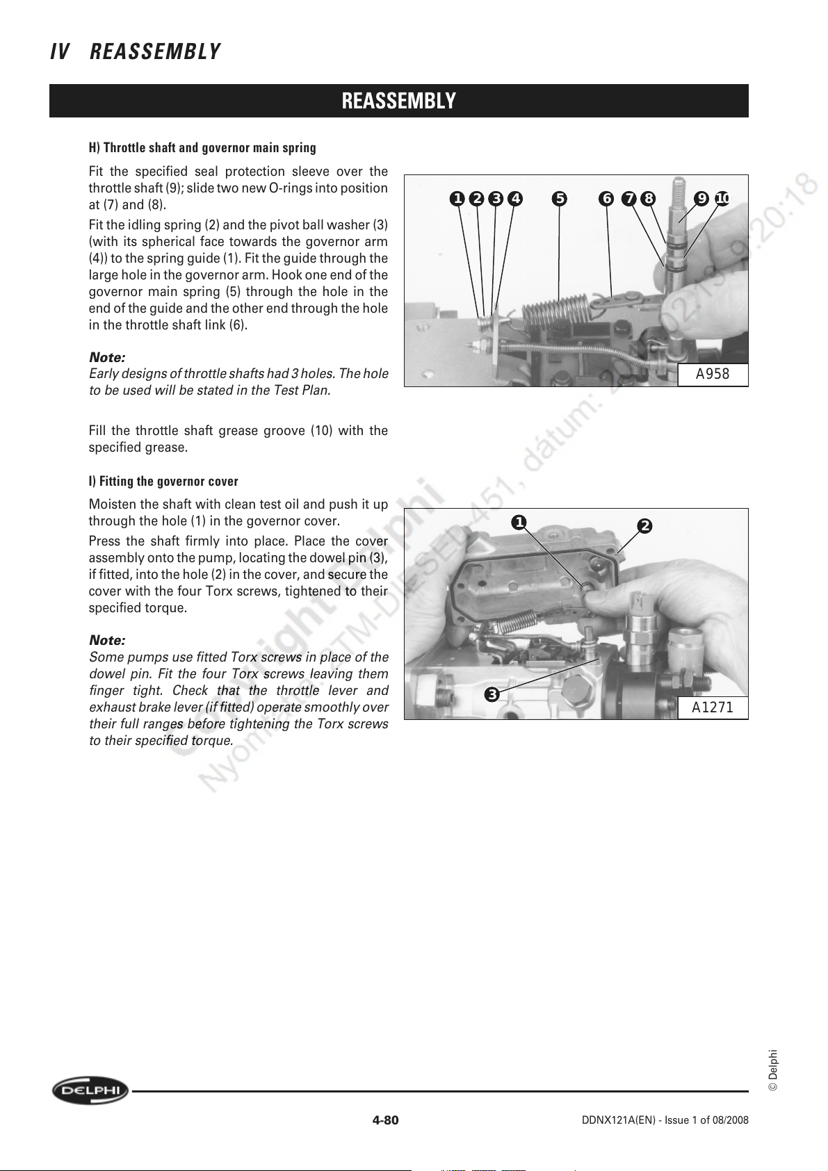
IV REASSEMBLY
H) Throttle shaft and governor main spring
Fit the specified seal protection sleeve over the
throttle shaft (9); slide two new O-rings into position
at (7) and (8).
Fit the idling spring (2) and the pivot ball washer (3)
(with its spherical face towards the governor arm
(4)) to the spring guide (1). Fit the guide through the
large hole in the governor arm. Hook one end of the
governor main spring (5) through the hole in the
end of the guide and the other end through the hole
in the throttle shaft link (6).
Note:
Early designs of throttle shafts had 3 holes. The hole
to be used will be stated in the Test Plan.
Fill the throttle shaft grease groove (10) with the
specified grease.
REASSEMBLY
10987654321
A958
I) Fitting the governor cover
Moisten the shaft with clean test oil and push it up
through the hole (1) in the governor cover.
Press the shaft firmly into place. Place the cover
assembly onto the pump, locating the dowel pin (3),
if fitted, into the hole (2) in the cover, and secure the
cover with the four Torx screws, tightened to their
specified torque.
Note:
Some pumps use fitted Torx screws in place of the
dowel pin. Fit the four Torx screws leaving them
finger tight. Check that the throttle lever and
exhaust brake lever (if fitted) operate smoothly over
their full ranges before tightening the Torx screws
to their specified torque.
1
3
2
A1271
4-80
© Delphi
DDNX121A(EN) - Issue 1 of 08/2008
Page 95
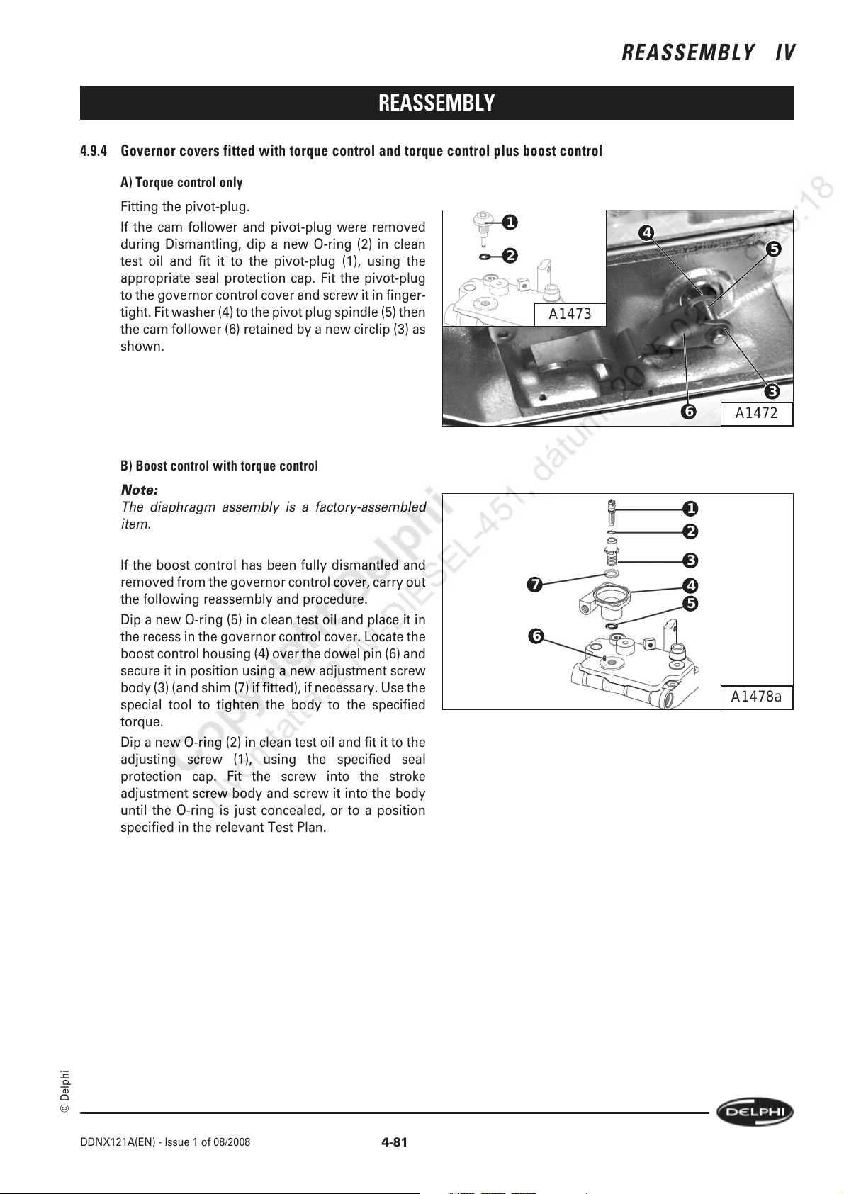
REASSEMBLY
4.9.4 Governor covers fitted with torque control and torque control plus boost control
A) Torque control only
Fitting the pivot-plug.
If the cam follower and pivot-plug were removed
during Dismantling, dip a new O-ring (2) in clean
test oil and fit it to the pivot-plug (1), using the
appropriate seal protection cap. Fit the pivot-plug
to the governor control cover and screw it in finger-
tight. Fit washer (4) to the pivot plug spindle (5) then
the cam follower (6) retained by a new circlip (3) as
shown.
B) Boost control with torque control
Note:
The diaphragm assembly is a factory-assembled
item.
1
2
A1473
REASSEMBLY IV
4
5
3
6
1
2
A1472
If the boost control has been fully dismantled and
removed from the governor control cover, carry out
the following reassembly and procedure.
Dip a new O-ring (5) in clean test oil and place it in
the recess in the governor control cover. Locate the
boost control housing (4) over the dowel pin (6) and
secure it in position using a new adjustment screw
body (3) (and shim (7) if fitted), if necessary. Use the
special tool to tighten the body to the specified
torque.
Dip a new O-ring (2) in clean test oil and fit it to the
adjusting screw (1), using the specified seal
protection cap. Fit the screw into the stroke
adjustment screw body and screw it into the body
until the O-ring is just concealed, or to a position
specified in the relevant Test Plan.
3
7
6
4
5
A1478a
© Delphi
DDNX121A(EN) - Issue 1 of 08/2008
4-81
Page 96
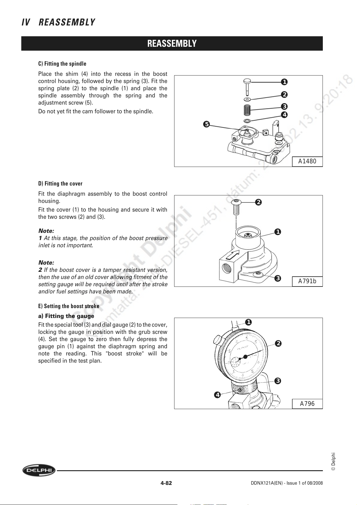
IV REASSEMBLY
C) Fitting the spindle
Place the shim (4) into the recess in the boost
control housing, followed by the spring (3). Fit the
spring plate (2) to the spindle (1) and place the
spindle assembly through the spring and the
adjustment screw (5).
Do not yet fit the cam follower to the spindle.
D) Fitting the cover
Fit the diaphragm assembly to the boost control
housing.
Fit the cover (1) to the housing and secure it with
the two screws (2) and (3).
REASSEMBLY
1
2
3
4
5
A1480
2
Note:
1 At this stage, the position of the boost pressure
inlet is not important.
Note:
2 If the boost cover is a tamper resistant version,
then the use of an old cover allowing fitment of the
setting gauge will be required until after the stroke
and/or fuel settings have been made.
E) Setting the boost stroke
a) Fitting the gauge
Fit the special tool (3) and dial gauge (2) to the cover,
locking the gauge in position with the grub screw
(4). Set the gauge to zero then fully depress the
gauge pin (1) against the diaphragm spring and
note the reading. This "boost stroke" will be
specified in the test plan.
1
3
1
2
3
4
A791b
A796
4-82
© Delphi
DDNX121A(EN) - Issue 1 of 08/2008
Page 97
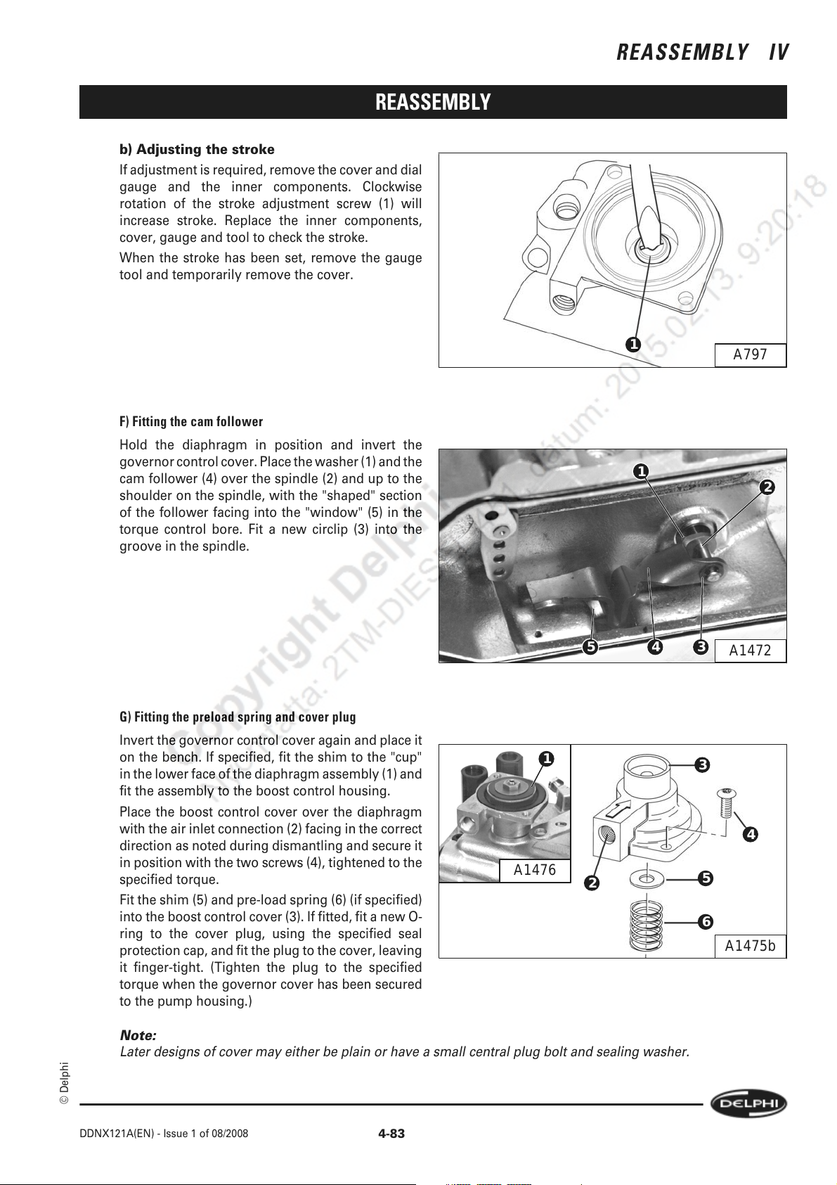
REASSEMBLY
b) Adjusting the stroke
If adjustment is required, remove the cover and dial
gauge and the inner components. Clockwise
rotation of the stroke adjustment screw (1) will
increase stroke. Replace the inner components,
cover, gauge and tool to check the stroke.
When the stroke has been set, remove the gauge
tool and temporarily remove the cover.
REASSEMBLY IV
F) Fitting the cam follower
Hold the diaphragm in position and invert the
governor control cover. Place the washer (1) and the
cam follower (4) over the spindle (2) and up to the
shoulder on the spindle, with the "shaped" section
of the follower facing into the "window" (5) in the
torque control bore. Fit a new circlip (3) into the
groove in the spindle.
G) Fitting the preload spring and cover plug
Invert the governor control cover again and place it
on the bench. If specified, fit the shim to the "cup"
in the lower face of the diaphragm assembly (1) and
fit the assembly to the boost control housing.
Place the boost control cover over the diaphragm
with the air inlet connection (2) facing in the correct
direction as noted during dismantling and secure it
in position with the two screws (4), tightened to the
specified torque.
Fit the shim (5) and pre-load spring (6) (if specified)
into the boost control cover (3). If fitted, fit a new O-
ring to the cover plug, using the specified seal
protection cap, and fit the plug to the cover, leaving
it finger-tight. (Tighten the plug to the specified
torque when the governor cover has been secured
to the pump housing.)
1
A1476
1
1
5 4 3
2
A797
2
A1472
3
4
5
6
A1475b
Note:
Later designs of cover may either be plain or have a small central plug bolt and sealing washer.
© Delphi
DDNX121A(EN) - Issue 1 of 08/2008
4-83
Page 98
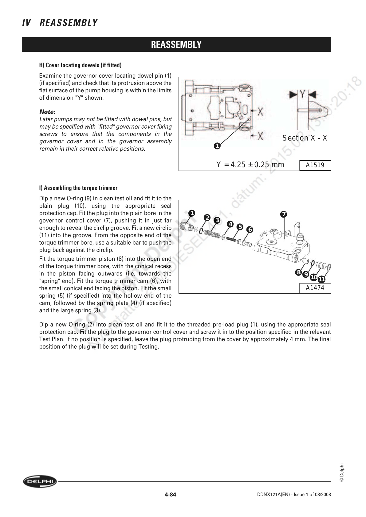
IV REASSEMBLY
H) Cover locating dowels (if fitted)
Examine the governor cover locating dowel pin (1)
(if specified) and check that its protrusion above the
flat surface of the pump housing is within the limits
of dimension "Y" shown.
Note:
Later pumps may not be fitted with dowel pins, but
may be specified with "fitted" governor cover fixing
screws to ensure that the components in the
governor cover and in the governor assembly
remain in their correct relative positions.
REASSEMBLY
Section X - X
1
8
A1519
9
10
A1474
11
Y = 4.25 ± 0.25 mm
I) Assembling the torque trimmer
Dip a new O-ring (9) in clean test oil and fit it to the
plain plug (10), using the appropriate seal
protection cap. Fit the plug into the plain bore in the
governor control cover (7), pushing it in just far
enough to reveal the circlip groove. Fit a new circlip
(11) into the groove. From the opposite end of the
torque trimmer bore, use a suitable bar to push the
plug back against the circlip.
Fit the torque trimmer piston (8) into the open end
of the torque trimmer bore, with the conical recess
in the piston facing outwards (i.e. towards the
"spring" end). Fit the torque trimmer cam (6), with
the small conical end facing the piston. Fit the small
spring (5) (if specified) into the hollow end of the
cam, followed by the spring plate (4) (if specified)
and the large spring (3).
Dip a new O-ring (2) into clean test oil and fit it to the threaded pre-load plug (1), using the appropriate seal
protection cap. Fit the plug to the governor control cover and screw it in to the position specified in the relevant
Test Plan. If no position is specified, leave the plug protruding from the cover by approximately 4 mm. The final
position of the plug will be set during Testing.
1
2
3
4
5
6
7
4-84
© Delphi
DDNX121A(EN) - Issue 1 of 08/2008
Page 99
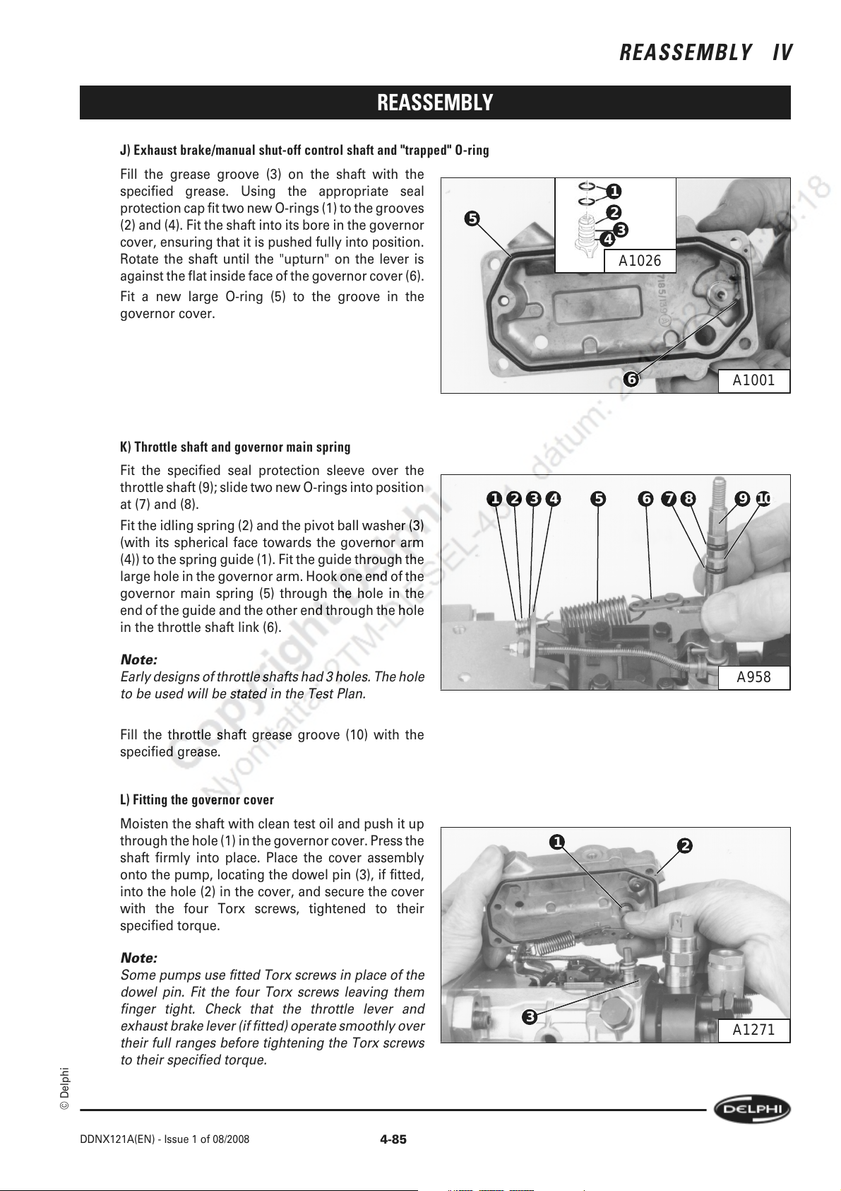
REASSEMBLY
J) Exhaust brake/manual shut-off control shaft and "trapped" O-ring
Fill the grease groove (3) on the shaft with the
specified grease. Using the appropriate seal
protection cap fit two new O-rings (1) to the grooves
(2) and (4). Fit the shaft into its bore in the governor
cover, ensuring that it is pushed fully into position.
Rotate the shaft until the "upturn" on the lever is
against the flat inside face of the governor cover (6).
Fit a new large O-ring (5) to the groove in the
governor cover.
5
REASSEMBLY IV
1
2
3
4
A1026
K) Throttle shaft and governor main spring
Fit the specified seal protection sleeve over the
throttle shaft (9); slide two new O-rings into position
at (7) and (8).
Fit the idling spring (2) and the pivot ball washer (3)
(with its spherical face towards the governor arm
(4)) to the spring guide (1). Fit the guide through the
large hole in the governor arm. Hook one end of the
governor main spring (5) through the hole in the
end of the guide and the other end through the hole
in the throttle shaft link (6).
Note:
Early designs of throttle shafts had 3 holes. The hole
to be used will be stated in the Test Plan.
Fill the throttle shaft grease groove (10) with the
specified grease.
6
A1001
10987654321
A958
L) Fitting the governor cover
Moisten the shaft with clean test oil and push it up
through the hole (1) in the governor cover. Press the
shaft firmly into place. Place the cover assembly
onto the pump, locating the dowel pin (3), if fitted,
into the hole (2) in the cover, and secure the cover
with the four Torx screws, tightened to their
specified torque.
Note:
Some pumps use fitted Torx screws in place of the
dowel pin. Fit the four Torx screws leaving them
finger tight. Check that the throttle lever and
exhaust brake lever (if fitted) operate smoothly over
their full ranges before tightening the Torx screws
to their specified torque.
© Delphi
DDNX121A(EN) - Issue 1 of 08/2008
4-85
1
3
2
A1271
Page 100
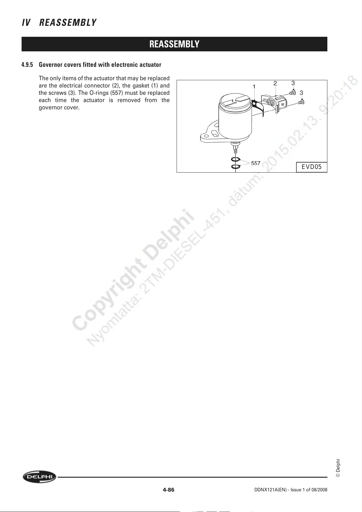
IV REASSEMBLY
REASSEMBLY
4.9.5 Governor covers fitted with electronic actuator
The only items of the actuator that may be replaced
are the electrical connector (2), the gasket (1) and
the screws (3). The O-rings (557) must be replaced
each time the actuator is removed from the
governor cover.
EVD05
4-86
© Delphi
DDNX121A(EN) - Issue 1 of 08/2008
 Loading...