

Page 1

WORKSHOP MANUAL
DPS FUEL INJECTION PUMP
2008
DDNX117A(EN)
Page 2

(D) Kommen Sie nicht mit dem Hochdruckstrahl in Verbindung! Besonders nicht, wenn
Druckrohrleitung oder Dichtung geprüft werden! Hochdruckflüssigkeiten können tödliche
Verletzungen verursachen! Im Falle einer Berührung mit der Haut, kontaktieren Sie
sofort einen Arzt. Bitte beachten Sie die Gesundheits-/und Sicherheitsunterlagen.
(E) Mantenga las manos y el cuerpo lejos del rociado del líquido, especialmente inyectores,
tuberías y juntas de alta presión con fugas. La inyección de alta presión puede perforar
la piel humana y producir una lesión fatal. En caso de que la inyección atraviese la piel,
consiga atención médica inmediatamente. Vea la hoja de Datos de Sanidad y
Seguridad.
(EN) Do not put your skin into the fuel jets under pressure, especially those due to pressure
pipe or seal leaks. High pressure liquids can cause deadly injuries. In case of an
injection under the skin, contact a doctor immediately. Please refer to the health and
security fuel documents.
(F) Ne pas approcher les mains ni le corps des jets de liquides, particulièrement ceux
provenant des fuites de tuyaux et des joint soumis a la haute pression. Le liquide sous
haute pression injecté sous la peau peut causer des blessures mortelles. En cas
d’injection sous la peau, consulter immédiatement un médecin. Se reporter a la fiche de
santé et de sécurité du gazole.
(IT) Non esporre le mani o altre parti del corpo a getti di gasolio ad alta pressione,
specialmente a quelli provenienti da tubi o paraolii. I getti di liquidi ad alta pressione
possono causare ferite anche mortali. In caso di iniezione sotto pelle contattare
immediatamente un medico. Fare riferimento alle schede di sicurezza del gasolio.
(NL) Zorg dat uw handen of andere lichaamsdelen niet in contact komen met vloeistofstralen
onder hoge druk, met name bij een lek aan een leiding of dichting. Als de vloeistof onder
hoge druk onder de huid terechtkomt, kan dit zelfs tot dodelijke verwondingen leiden. Als
de vloeistof onder de huid terechtkomt, onmiddellijk een arts raadplegen. Lees de
gezondheids- en veiligheidsfiche met betrekking tot de brandstof.
(P) Não exponha a pele a jactos de combustível sob pressão, especialmente os devidos a
fugas de tubos de pressão ou vedantes. Líquidos a alta pressão podem causar
ferimentos mortais. No caso de injecção subcutânea, consulte imediatamente um
médico. Consulte por favor a documentação respeitante a saúde e segurança de
combustíveis.
(D) Schutzbrille/Gesichtsschutz tragen.
(E) Úsese protección para los ojos/la cara.
(EN) Wear eye/face protection.
(F) Porter un appareil de protection des yeux / du visage.
(IT) Proteggersi gli occhi/la faccia.
(NL) Veiligheidsbril/-masker gebruiken.
(P) Use protecção da face/olhos.
(D) Von Zündquellen fernhalten - Nicht rauchen.
(E) Conservar alejado de toda llama o fuente de chispas -No fumar.
(EN) Keep away from sources of ignition - No smoking.
(F) Conserver à l'écart de toute flamme ou source d'étincelles - Ne pas fumer.
(IT) Conservare lontano da fiamme e scintille - Non fumare.
(NL) Ver van open vuur en ontstekingsbronnen houden – Niet roken.
(P) Mantenha afastado de fontes de ignição – Proibido fumar.
(D) Geeignete Schutzhandschuhe tragen.
(E) Usen guantes adecuados.
(EN) Wear suitable gloves.
(F) Porter des gants appropriés.
(IT) Usare guanti adatti.
(NL) Aangepaste veiligheidshandschoenen dragen.
(P) Use luvas apropriadas.
Page 3

INTRODUCTION I
DISMANTLING II
COMPONENT INSPECTION AND RENEWAL III
REASSEMBLY IV
TESTING V
TABLE OF CONTENTS
DDNX117A(EN) - Issue 1 of 08/2008
i
© Delphi
Page 4

APPENDIX VI
Produced and published by:
Delphi Diesel Systems Ltd.
Spartan Close
Warwick CV34 6AG Tel: +44 (0) 1926 472 900
England Fax: +44 (0) 1926 472 901
TABLE OF CONTENTS
ii
DDNX117A(EN) - Issue 1 of 08/2008
© Delphi
Page 5

1.
INTRODUCTION
1.1 The Pump.......................................................................................................................................................................1-1
1.2 General...........................................................................................................................................................................1-2
1.3 This Manual...................................................................................................................................................................1-2
1.4 Equipment......................................................................................................................................................................1-2
1.5 Pump Name Plate..........................................................................................................................................................1-3
1.6 Replacement Of Parts...................................................................................................................................................1-4
INTRODUCTION I
TABLE OF CONTENTS
DDNX117A(EN) - Issue 1 of 08/2008
iii
© Delphi
Page 6

2.
DISMANTLING
2.1 Preparation....................................................................................................................................................................2-5
2.1.1 Cleaning and draining..................................................................................................................................2-5
2.1.2 Mounting the pump and initial inspection.................................................................................................2-5
2.1.3 General..........................................................................................................................................................2-5
2.1.4 Measuring drive shaft end float..................................................................................................................2-6
2.1.5 Measuring drive shaft radial play...............................................................................................................2-6
2.1.6 Removing sealing caps and locking wire...................................................................................................2-7
2.2 Governor Cover, Link Assembly & Control Levers.....................................................................................................2-7
2.2.1 Backleak connection, throttle lever stop screws and maximum fuel screw...........................................2-7
2.2.2 Cold idle advance (CIA) linkage..................................................................................................................2-8
2.2.3 Light load advance (LLA) linkage................................................................................................................2-8
2.2.4 Throttle lever................................................................................................................................................2-9
2.2.5 Torque trimmer..........................................................................................................................................2-10
2.2.6 Boost control device..................................................................................................................................2-11
2.2.7 Governor cover removal............................................................................................................................2-13
2.2.8 Dismantling the governor cover assembly..............................................................................................2-15
2.2.9 Throttle shaft and governor spring...........................................................................................................2-17
2.2.10 Control bracket and governor assembly..................................................................................................2-18
2.2.11 Governor control arm assembly and idle actuator.................................................................................2-20
2.3 High Pressure Outlets, End Plate Assembly, Shut-Off Solenoid & Transfer Pump...............................................2-21
2.3.1 High pressure outlets.................................................................................................................................2-21
2.3.2 End plate assembly....................................................................................................................................2-22
2.3.3 Shut-off solenoid........................................................................................................................................2-23
2.3.4 Transfer pump............................................................................................................................................2-23
2.4 Advance Device, Latch Valve And Rotor Vent Switch Valve...................................................................................2-24
2.4.1 Dismantling the advance device...............................................................................................................2-24
2.4.2 Advance housing........................................................................................................................................2-26
2.4.3 Latch valve..................................................................................................................................................2-27
2.4.4 Rotor vent switch valve.............................................................................................................................2-28
2.5 Hydraulic Head And Drive Shaft Assembly..............................................................................................................2-28
2.5.1 Releasing the hydraulic head....................................................................................................................2-28
2.5.2 Removing the drive shaft nut, key and thrust washer............................................................................2-29
2.5.3 Dismantling the shaft assembly................................................................................................................2-31
2.5.4 Pump housing............................................................................................................................................2-32
2.6 Removal Of The Head And Rotor Only......................................................................................................................2-33
2.6.1 Preparation.................................................................................................................................................2-33
2.6.2 Transfer pump and head fittings..............................................................................................................2-33
2.6.3 Releasing the hydraulic head....................................................................................................................2-34
II DISMANTLING
TABLE OF CONTENTS
iv
DDNX117A(EN) - Issue 1 of 08/2008
© Delphi
Page 7

3.
COMPONENT INSPECTION AND RENEWAL
3.1 Cleaning.......................................................................................................................................................................3-35
3.2 General.........................................................................................................................................................................3-35
3.2.1 Mated and matched assemblies...............................................................................................................3-35
3.2.2 Examination and replacement..................................................................................................................3-35
3.2.3 Seals............................................................................................................................................................3-35
3.3 Details...........................................................................................................................................................................3-36
3.3.1 Hydraulic head rotor..................................................................................................................................3-36
3.3.2 Hydraulic head plungers............................................................................................................................3-36
3.3.3 Cam ring and scroll plates.........................................................................................................................3-36
3.3.4 Rollers and shoes.......................................................................................................................................3-36
3.3.5 Transfer pump............................................................................................................................................3-36
3.3.6 End plate and transfer pump liner............................................................................................................3-36
3.3.7 Control valves.............................................................................................................................................3-36
3.3.8 Delivery valves and cambox pressurising valves....................................................................................3-37
3.3.9 High pressure outlet pressurising valves.................................................................................................3-37
3.3.10 Springs........................................................................................................................................................3-37
3.3.11 Fittings and threads...................................................................................................................................3-37
3.3.12 Linkages......................................................................................................................................................3-37
3.3.13 Control shafts.............................................................................................................................................3-37
3.3.14 Drive shaft and associated component....................................................................................................3-38
3.3.15 Advance device..........................................................................................................................................3-38
3.3.16 Levers and external controls.....................................................................................................................3-38
3.3.17 Pump housing............................................................................................................................................3-38
3.3.18 Orifices........................................................................................................................................................3-38
3.3.19 Electrical connections................................................................................................................................3-38
3.3.20 Oversize metering valves..........................................................................................................................3-38
COMPONENT INSPECTION AND RENEWAL III
TABLE OF CONTENTS
DDNX117A(EN) - Issue 1 of 08/2008
v
© Delphi
Page 8

4.
REASSEMBLY
4.1 Preparation..................................................................................................................................................................4-39
4.2 Drive Shaft Assembly, Governor Weight Cage, Pump Housing, Head And Rotor................................................4-39
4.2.1 Drive shaft assembly..................................................................................................................................4-39
4.2.2 Governor weight cage and drive shaft assembly....................................................................................4-40
4.2.3 Inner bearing, scroll plates, and cam ring................................................................................................4-41
4.2.4 Hydraulic head rotor plug..........................................................................................................................4-43
4.2.5 Assembly of the drive shaft to the hydraulic head..................................................................................4-43
4.2.6 Housing.......................................................................................................................................................4-44
4.2.7 Fitting the pump housing to the drive shaft and hydraulic head...........................................................4-44
4.2.8 Transfer pump rotor...................................................................................................................................4-45
4.2.9 Drive shaft oil seals....................................................................................................................................4-46
4.2.10 Checking end-float and radial play...........................................................................................................4-47
4.2.11 Fitting the drive shaft key or pin...............................................................................................................4-48
4.3 Hydraulic Head And Rotor..........................................................................................................................................4-48
4.3.1 Rotor plug...................................................................................................................................................4-48
4.3.2 Preparation of the hydraulic head............................................................................................................4-49
4.3.3 Fitting the hydraulic head to the pump housing.....................................................................................4-49
4.3.4 Final location of the hydraulic head.........................................................................................................4-49
4.3.5 Checking drive shaft end-float..................................................................................................................4-49
4.4 Cam Screw, Servo Piston, Adv. Housing, Latch Valve, Rotor Vent Switch Valve, Head Locking Screw.............4-50
4.4.1 Cam screw..................................................................................................................................................4-50
4.4.2 Servo piston................................................................................................................................................4-50
4.4.3 Fitting the advance housing......................................................................................................................4-51
4.4.4 Hydraulic head fixings...............................................................................................................................4-51
4.4.5 Advance device fittings (pressure end)....................................................................................................4-54
4.4.6 Advance device fittings (spring end)........................................................................................................4-55
4.5 Transfer Pump, End Plate Assembly, Stop Solenoid, High Pressure Outlets........................................................4-58
4.5.1 Transfer pump............................................................................................................................................4-58
4.5.2 End plate.....................................................................................................................................................4-58
4.5.3 Stop solenoid or blanking plug.................................................................................................................4-60
4.5.4 High pressure outlets.................................................................................................................................4-60
4.6 Governor Linkage, Idle Actuator, Support Plate, Cover...........................................................................................4-62
4.6.1 Governor linkage........................................................................................................................................4-62
4.6.2 Idle actuator................................................................................................................................................4-63
4.6.3 Fitting the support plate............................................................................................................................4-63
4.6.4 Assembling the governor cover................................................................................................................4-66
4.6.5 Fitting the governor cover.........................................................................................................................4-71
4.6.6 Aligning / fitting external levers................................................................................................................4-75
4.6.7 Control stop screws...................................................................................................................................4-78
4.6.8 Boost control device..................................................................................................................................4-80
4.6.9 Fuel connections, timing cover or plug, light load advance lever, cold idle advance linkage............4-85
4.6.10 External brackets, drive hub and timing adaptor....................................................................................4-88
IV REASSEMBLY
TABLE OF CONTENTS
vi
DDNX117A(EN) - Issue 1 of 08/2008
© Delphi
Page 9

5.
TESTING
5.1 Preparation..................................................................................................................................................................5-89
5.1.1 Leak testing.................................................................................................................................................5-89
5.1.2 Test machine..............................................................................................................................................5-89
5.1.3 Test machine drive.....................................................................................................................................5-90
5.1.4 Test conditions...........................................................................................................................................5-90
5.1.5 Connecting fuel lines.................................................................................................................................5-90
5.1.6 Machine test procedure.............................................................................................................................5-91
5.1.7 Transfer pressure measurement and initial setting................................................................................5-91
5.1.8 Cambox pressure measurement...............................................................................................................5-92
5.1.9 Adjustments to be pre-set.........................................................................................................................5-92
5.2 Test Procedure.............................................................................................................................................................5-97
5.2.1 Priming........................................................................................................................................................5-97
5.2.2 Checking and setting transfer pressure....................................................................................................5-97
5.2.3 Cambox pressure and backleakage checks..............................................................................................5-98
5.2.4 Speed advance setting...............................................................................................................................5-98
5.2.5 Light load advance (HSDI).........................................................................................................................5-99
5.2.6 Cold idle advance (HSDI).........................................................................................................................5-100
5.2.7 Latch valve setting...................................................................................................................................5-101
5.2.8 Rotor vent switch valve...........................................................................................................................5-102
5.2.9 Excess fuel................................................................................................................................................5-102
5.2.10 Maximum fuel delivery setting...............................................................................................................5-102
5.2.11 Governor setting and testing..................................................................................................................5-106
5.2.12 Anti-stall screw and idling control setting.............................................................................................5-108
5.2.13 Stop control check....................................................................................................................................5-110
5.3 Timing........................................................................................................................................................................5-110
5.3.1 General......................................................................................................................................................5-110
5.3.2 Preparation...............................................................................................................................................5-111
5.3.3 Flange marking method...........................................................................................................................5-112
5.3.4 Peg-timing method..................................................................................................................................5-113
5.4 Leakage Testing.........................................................................................................................................................5-117
TESTING V
TABLE OF CONTENTS
DDNX117A(EN) - Issue 1 of 08/2008
vii
© Delphi
Page 10

6.
APPENDIX
6.1 Torque Values............................................................................................................................................................6-119
6.1.1 End plate, brackets, hydraulic head and rotor.......................................................................................6-119
6.1.2 Governor and housing assemblies.........................................................................................................6-120
6.1.3 Auto advance arrangement.....................................................................................................................6-121
6.1.4 Pump body, drive shaft and throttle bracket.........................................................................................6-122
6.2 Special Tools And Fittings (Repair).........................................................................................................................6-122
6.3 Materials....................................................................................................................................................................6-124
6.4 Special Tools And Materials (Test)..........................................................................................................................6-125
6.5 Abbreviations Used In This Manual........................................................................................................................6-127
VI APPENDIX
TABLE OF CONTENTS
viii
DDNX117A(EN) - Issue 1 of 08/2008
© Delphi
Page 11
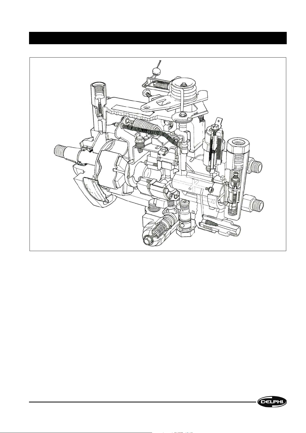
1.1 The Pump
The DPS distributor-type fuel injection pump is a compact self-contained unit which is suitable for highspeed diesel
engines of up to two litres swept volume per cylinder and two, three, four or six cylinders. All internal working parts are
lubricated by fuel oil and the pump housing is maintained at a pressure which prevents the ingress a[ external dirt or
other foreign matter.
It can be specified for direct or indirect injection engines and can be fitted with a range of options to produce performance
curves to match a wide variety of engine requirements, including boost-pressure control of delivery level for
turbocharged engines.
Due to the complexity of this product, the need for highly-trained personnel, a high level of investment in equipment
and workshop resources, together with the need for continual up-dating of technical data such as Test Plans and Service
Information, it can only be tested or serviced by Delphi Authorised Distributors.
The expression "HSDI" is used to describe a particular pump specification. It is the abbreviation of "High Speed Direct
Injection" and it refers to pumps which cater for the particular requirements of engines of this type.
INTRODUCTION I
INTRODUCTION
DDNX117A(EN) - Issue 1 of 08/2008
1-1
© Delphi
Page 12

1.2 General
Fuel pumps may require off-engine workshop attention for two main reasons:
a. Investigation of a specific fault in engine performance which may only require partial dismantling.
b. A complete overhaul e.g. at the same time as a major high-mileage engine overhaul. A full performance test is
recommended, both before and after any level of attention, as many aspects of performance are inter-related.
1.3 This Manual
This Workshop Manual is divided into the following sections:
1. Section 1 - Introduction
2. Section 2 - Dismantling
3. Section 3 - Component inspection
4. Section 4 - Reassembly
5. Section 5 - Testing
6. Section 6 - Appendix (Technical Information, Tools etc.).
Each section is laid out on a step-by-step basis, with each action accompanied by an illustration showing the component
(s) involved and, where applicable, its/their position(s) on the pump. The Manual is not based on any one particular
pump specification, but covers pump features which have been included up to the time of publication. For the purposes
of illustration, several pump specifications have been used.
The pumps illustrated are for clockwise rotation (when viewed from the drive end); anticlockwise pumps will have items
such as the maximum fuel screw, hydraulic excess fuel control, latch valve and boost control fitted on the side opposite
to that shown.
Instructions for both full and partial dismantling of the pump are included e.g. total dismantling and examination of all
components other than those which are factory-sealed units, and removal of the hydraulic head and rotor only.
All the necessary tools are listed in
Section 6. Special tools are identified by part number and standard tools by type and
size.
1.4 Equipment
Any tools, both standard and special-purpose, used for the servicing or repair of fuel injection equipment (FIE) must be
reserved solely for use on FIE. Worn or damaged tools can cause damage to critical components, as well as being a
safety hazard.
The working area must be scrupulously clean and should be in a room separated from any other activity; the ingress of
dust and dirt, airborne or otherwise, should be prevented.
The minimum facilities required are:
1. A bench covered in non-rusting metal or industrial-grade linoleum and fitted with an engineer's vice with a jaw
size of 100mm (4 in.). The vice jaws must be faced with either soft metal or fibre pads.
2. An adjustable pump-mounting device such as the Hartridge "Hydraclamp", fitted with an appropriate adaptor plate.
3. Easily-cleaned compartmented trays for separate storage of dismantled components.
4. All the necessary tools as listed in
Section 6 of this Manual.
5. A low-pressure washing facility using a suitable, approved, cleaning fluid (not water or water-based) to clean pumps
externally prior to dismantling. Cleaning must be carried out in a place separated from the "clean area".
6. A tank large enough to accommodate a complete pump and filled with clean test oil, near to a source of clean, dry,
variable pressure compressed air for carrying out leakage tests.
7. A supply of clean, lint-free (non-fluffy) cloths for cleaning and drying components. Cotton waste must never be
used.
8. A pump test machine which conforms to ISO 4008.
I INTRODUCTION
INTRODUCTION
1-2
DDNX117A(EN) - Issue 1 of 08/2008
© Delphi
Page 13
9. Adequate storage facilities for pumps, tools and test equipment, with separate areas for pumps before and after
repair.
Note: All cleaning tanks, workshop and test facilities and fluids must conform to any Fire Prevention or Health and
Safety Regulations in force at the time of use.
1.5 Pump Name Plate
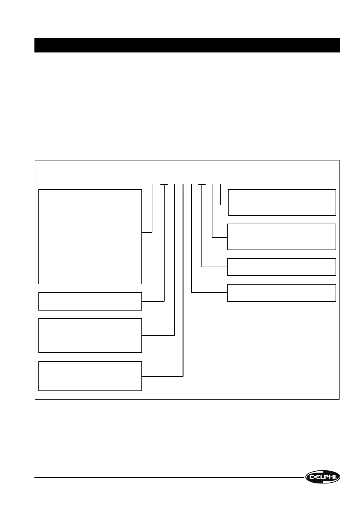
The number stamped on the name plate attached to the pump housing identifies the type and model of the pump. Pumps
which are of identical build, but with modified settings for different applications, are further identified by the Setting
Code stamped beneath the Despatch Number.
A typical Despatch Number could be as shown below:
Marketing Code: (See Note)
R = France
C= Spain
G = India
M = Mefin, Romania
P = WSK Poznan, Poland
V=Brazil
U = Greenville, USA
J = Kk, Japan
No prefix letter = UK
Note: This letter will not be used in
future Service documentation.
This character indicates whether or not an
ESOS is fitted to the pump and, if so, its
type. (For more details, see SIN DT294).
Changes to the individual specification
affecting parts interchangeability, but not
fit or function of the pump.
Individual features number.
Design change letter.
(No significance at present).
Product type (DPS)
Design Source Code
0 = USA 1 = Korea 2 & 3 = UK
4 = France 5 = Spain 6 = Brazil
7 = India 8 = Poland 9 = Japan
Number of delivery ports
0 = 4 1 = 6 2 = 3 cylinders
3 = 4 4 = 6 cylinders
5-9 to be allocated
C
85 2 0 A 06 0 A
Note: If the name plate has been painted over, special care is needed when removing the paint to avoid erasure of the
information. Use a small quantity of proprietary paint stripper, carefully observing the manufacturer's instructions.
INTRODUCTION I
INTRODUCTION
DDNX117A(EN) - Issue 1 of 08/2008
1-3
© Delphi
Page 14

1.6 Replacement Of Parts
All gaskets and seals must be replaced during reassembly. However, in the event of partial dismantling, only those seals
which have been disturbed need replacement, unless leaks from elsewhere are detected during testing prior to
dismantling.
If any part of a "mated" assembly is worn or damaged, the whole assembly must be replaced. Any component showing
signs of corrosion or water ingress, cracks or distortion must be replaced.
It is imperative that only service parts supplied by Delphi Aftermarket Operations are used as replacements. Parts
supplied from alternative sources may appear to be externally similar and may carry the same part numbers as the
genuine item but may be inferior in material specification or finish and lead to malfunction or premature failure.
I INTRODUCTION
INTRODUCTION
1-4
DDNX117A(EN) - Issue 1 of 08/2008
© Delphi
Page 15

2.1 Preparation
Note: A list of all tools required, together with toque values for all fixings, is contained in Section 6.
2.1.1 Cleaning and draining
Externally clean the pump. Remove the drain plug
or inspection cover on the side of the pump and
drain any fuel oil remaining in the housing. In the
case of HSDI pumps slacken, but do not remove, the
cover plate. If the pump is to have a possible defect
rectified or is subject to a warranty assessment, a
preliminary test on the test machine may be
required. In this case externally clean the pump as
above but drain the fuel oil into a clean container
for possible subsequent analysis.
Note: Before disturbing any component which is
required to indicate timing, e.g. the cover plate,
check that It is not necessary to confirm the
accuracy of the timing position in response to, say,
a warranty claim.
2.1.2 Mounting the pump and initial inspection
Mount the pump on a Hydraclamp using a Hartridge
mounting plate (1) and, depending on the pump
spigot diameter, either a 46mm or 50mm bore
adaptor ring (2). Remove the drive flange, hub, gear
or pulley and the timing adaptor, if fitted. In the case
of HSDI pumps, no adaptor is required until the
drive and timing components have been removed.
If the pump has not seized, and it requires a machine
test prior to dismantling, further examination will
first be necessary to determine if dirt or water
ingress has occurred, so as to avoid damage to the
test equipment. In most cases viewing of the
internal components through the inspection
aperture may be adequate, but if any doubt exists
remove the advance device and closely examine the
components for signs of wear, corrosion or metal
particles.
2.1.3 General
Remove any external brackets, such as those used for mounting control cable ends, noting their positions and
components.
Inspect all components as they are removed and put those considered unfit for further service to one side for
replacement. A guide to areas of possible wear or damage appears in
Section 3 (Component Inspection &
Renewal).
DISMANTLING II
DISMANTLING
DDNX117A(EN) - Issue 1 of 08/2008
2-5
© Delphi
Page 16

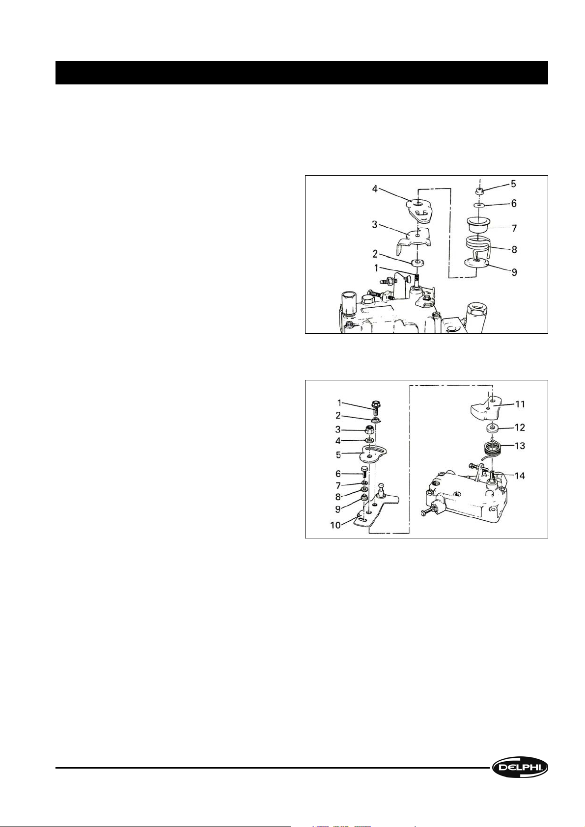
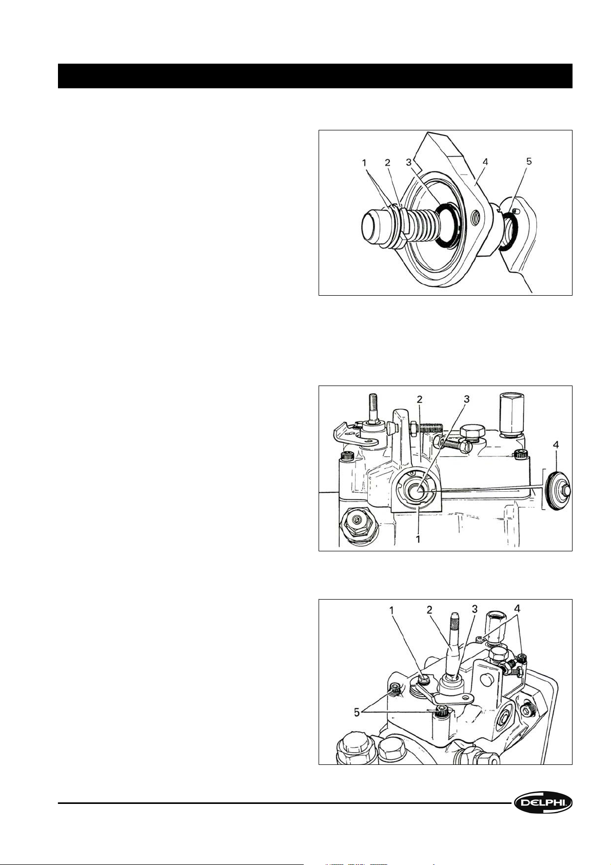
2.1.4 Measuring drive shaft end float
Note: The pump and gauge must be clamped to
an assembly plate mounted in a vice or on a
Hydraclamp.
Fit the appropriate adaptor (1) to the drive shaft
thread. Screw in the dial gauge holder (2), and fit
the gauge (4). Adjust the gauge pin to contact the
pump housing at (3). Push the drive shaft inwards
and set the dial gauge to zero. Pull the drive shaft
outwards and note the maximum gauge reading.
End-float should be 0.05mm to 0.2mm. If the
maximum is exceeded, examine the housing thrustfaces during dismantling. If no significant wear or
damage is apparent, requiring replacement of the
pump housing, correct the end-float by the use of
alternative shims during reassembly.
2.1.5 Measuring drive shaft radial play
With the pump and gauge (1) mounted rigidly
relative to each other adjust the gauge pin to bear
against the drive shaft (2). Push the shaft radially
towards the gauge and set the gauge to zero. Pull
the shaft radially to the opposite extreme and
record the gauge movement. Repeat the readings
with the gauge repositioned as shown at (3) and (4).
Do not rotate the drive shaft. Reject the housing if
the max, play or the difference between the
measurements exceed the figures in the table
below.
Drive type Max. play Max. difference
Belt 0.22mm 0.1mm
Gear or hub 0.27mm 0.2mm
II DISMANTLING
DISMANTLING
2-6
DDNX117A(EN) - Issue 1 of 08/2008
© Delphi
Page 17

2.1.6 Removing sealing caps and locking wire
Remove any shrink-sleeving, sealing caps or
locking wire from adjustment screws. In the
illustration the maximum speed adjusting screw (1),
latch valve (2) and the maximum fuel screw (3) are
shown sealed.
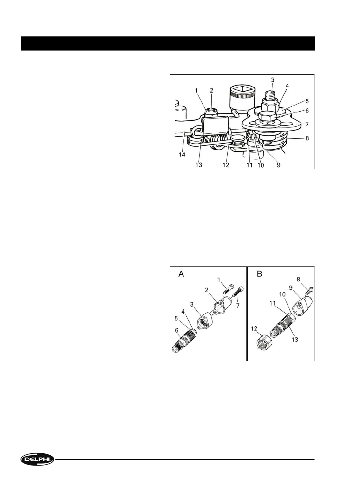
2.2 Governor Cover, Link Assembly & Control Levers
2.2.1 Backleak connection, throttle lever stop screws and maximum fuel screw
Loosen, but do not remove, the backleak connection
(1) or the pressurising valve, if fitted.
Loosen the governor cover plug (2) or vent screw,
whichever is fitted. Loosen the lock-nuts (3), (4), (5)
and remove their respective control screws.
Note: The position of the maximum fuel screw on
the governor cover may differ from one type of
pump to another, depending on the application. For
pumps fitted with boost control, maximum fuel
adjustment is incorporated within the boost control
device. On HSDI pumps, maximum fuel is set with
the torque trimmer.
DISMANTLING II
DISMANTLING
DDNX117A(EN) - Issue 1 of 08/2008
2-7
© Delphi
Page 18

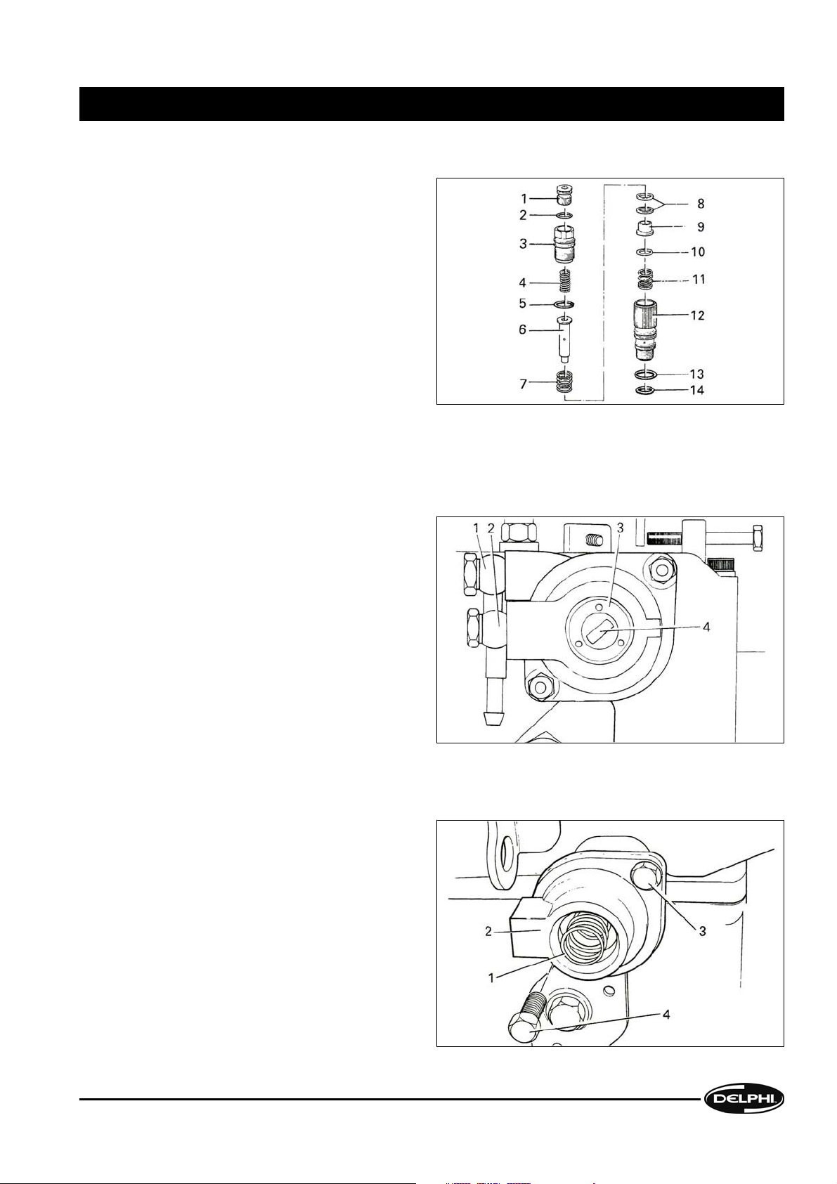
2.2.2 Cold idle advance (CIA) linkage
Remove and discard the plastic protection cap (1).
Using a suitable lever with no sharp edges, remove
the CIA link (3) and the fast idle link (5). Both of these
parts are plastic and particular care must be taken
when dismantling.
Remove the C-clip (11) from the lever pivot on the
cover plate (7). Unscrew and remove the cover plate
screws (2) and (10), discard the star washers (9) and
(12) and detach the cover plate (7). Remove and
discard the O-ring (6).
Slide the lever (4) off the pivot and unhook the
spring (8) .
2.2.3 Light load advance (LLA) linkage
Unscrew and remove the LLA cam follower locknut
(1) and the washer (2). Slacken and remove the grub
screw (3), if fitted.
Remove the cap (6) from the rocker arm pivot (12).
Detach the circlip (7) followed by the thin and thick
washers (8) and (9).
Slide the rocker arm (10) on its pivot towards the
rear of the pump. Unscrew the pivot and remove
the rocker arm, dust cap (11) and pivot from the
pump housing. Remove the flexible dust cover (13)
and the cam follower (5) from the rocker arm and
unscrew the lock-nut (4).
Note: The cam follower may be in the form of
either a roller or, on later pumps, a captive ball.
II DISMANTLING
DISMANTLING
2-8
DDNX117A(EN) - Issue 1 of 08/2008
© Delphi
Page 19
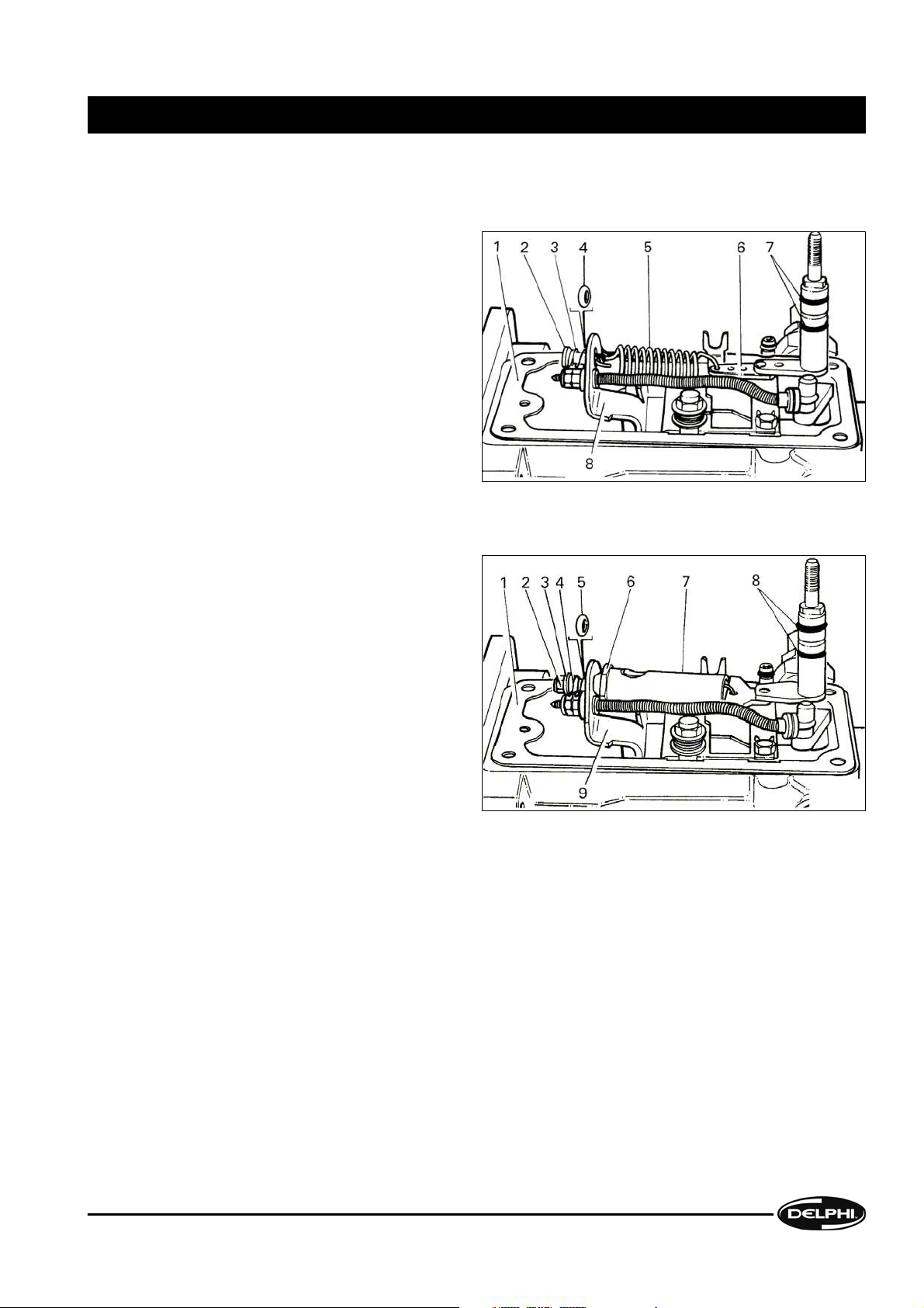
2.2.4 Throttle lever
Make a note of how the individual components of the throttle lever assembly are fitted together. The throttle lever
arrangement will differ according to the specification of the pump; the principle types are covered below.
A) Throttle lever without vernier plate
Remove the following from the throttle shaft (1); nut
(9, washer (6), spring guide (7), spring (8), lower
spring seat (9), throttle lever (4), break-back lever (3)
and dust cover (2).
B) Throttle lever with vernier plate
Slacken and remove the vernier plate securing bolt
(1) and collar (2). Remove the LLA cam vernier
locking bolt (6), spring washer (7), flat washer (8)
and collar (9), if fitted.
Remove the nut (3) and washer (4) from the throttle
shaft (14). Note which way up the vernier plate (5)
is fitted before removing it (the shaft hole may not
be centrally placed relative to the curved slot).
Remove the throttle lever assembly (10), LLA cam
(11), dust cover (12), and throttle lever return spring
(13).
DISMANTLING II
DISMANTLING
DDNX117A(EN) - Issue 1 of 08/2008
2-9
© Delphi
Page 20
C) Throttle lever with vernier plate (pumps with mechanical excess fuel)
Place a suitable socket over the governor cover vent
screw to act as a temporary stop for the throttle
lever. Remove the external bracket, slacken the
excess fuel linkage spring peg nut (1) and the
throttle shaft nut (4). Remove the vernier plate bolt
(6), together with the spring and flat washers.
Unhook the excess fuel linkage springs (12) and (13)
from the plate (11).
Hold the throttle lever (14) and remove the governor
cover vent screw assembly. Allow the throttle lever
to rotate clockwise and lift it over the idling shaft.
Remove the linkage spring, nut (1), washer and peg
(2). Remove nut (9), washer, plate, and washer from
the excess fuel shaft (10).
Remove throttle shaft nut (4), washer (5), and vernier plate (7) from the throttle shaft (3). Unhook the return spring
(8) and remove it with the throttle lever. Remove the cap washer which is beneath the lever. Remove the tension
spring (13) from the throttle lever.
D) Single-piece throttle lever
Remove the retaining nut and washers and lift the lever and return spring off the throttle shaft.
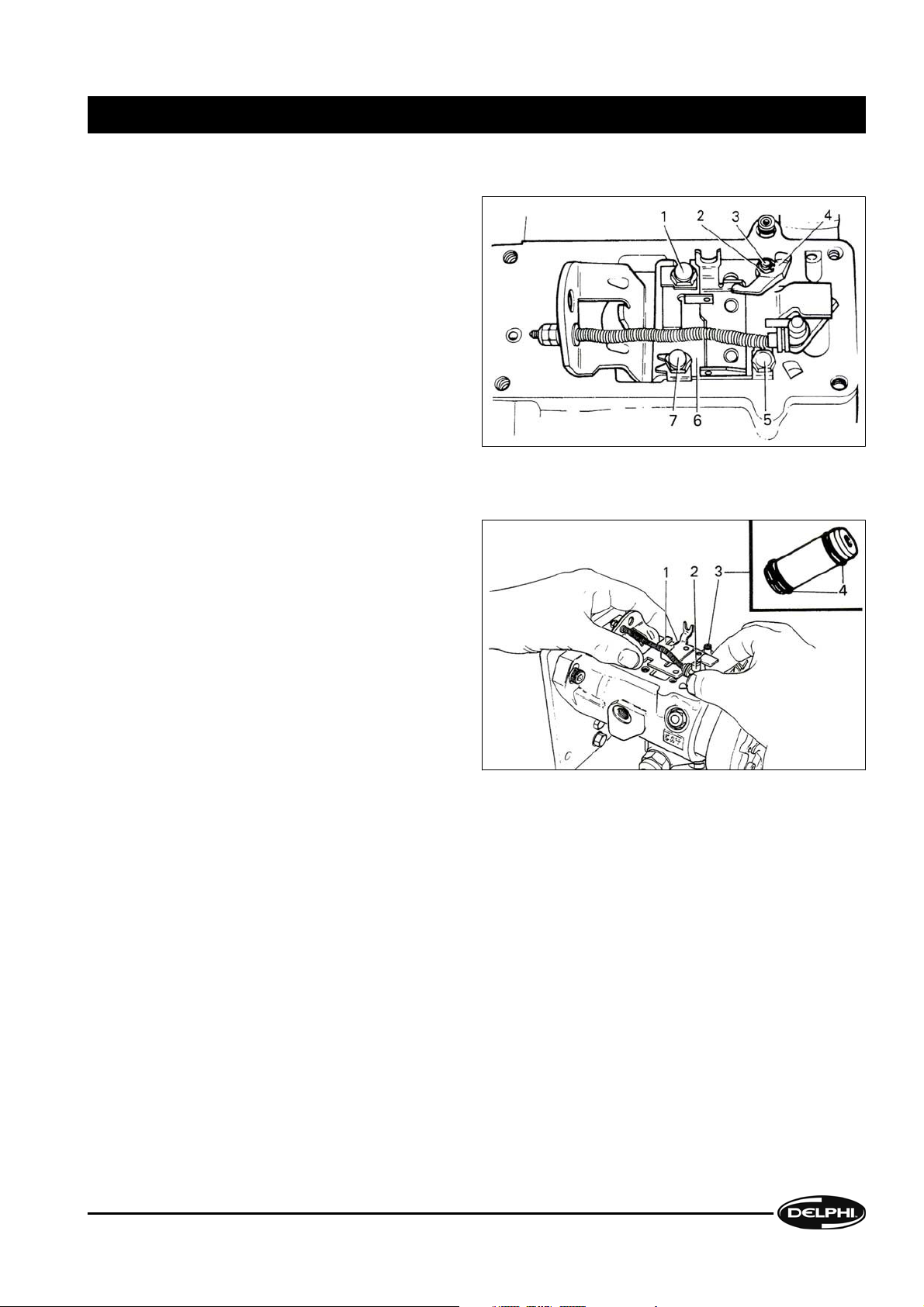
2.2.5 Torque trimmer
A) Removing
(i) Early type [A]
Cut a slot in the tamperproof screw head (1) with a
hacksaw and remove it, together with the socket
headed screw (7) and the cover (2).
Slacken the pre-load adjuster (4) and stroke adjuster
(5). Use the locking plate (3) to remove the torque
trimmer (6) from the governor cover.
(ii) Later type [B]
Cut a slot in the tamperproof screw head (8) with a hacksaw; it will be necessary to cut into the plastic cap (9).
Remove the screw and discard the plastic cap. Slacken the pre-load and stroke adjusters (10) and (11), then locknut
(12). Remove the torque trimmer (13) from the governor cover.
II DISMANTLING
DISMANTLING
2-10
DDNX117A(EN) - Issue 1 of 08/2008
© Delphi
Page 21
B) Dismantling
Remove the pre-load adjuster (1), together with the
pre-load spring (4); remove and discard the O-ring
(2). Unscrew the stroke adjuster (3) and discard the
O-ring (5).
Tip out the plunger (6) and springs from the body
(12) and discard the two O-rings (13) & (14) from the
body. Slide the following components off the
plunger: small spring (11), shim (10) (if fitted), guide
(9), shim(s) (8) and large spring (7).
2.2.6 Boost control device
A) Removing the pipe connectors & spring adjuster
Note the positions of the two external pipe
connections (1) & (2), if fitted, then unscrew and
remove them. Unscrew and remove the locking ring
(3) and spring adjuster (4), using the special tool.
Note: On some units the locking ring and spring
adjuster are replaced by a plug and shims; in this
case the special tool will not be required.
B) Removing the cover
Remove the pre-load spring (1) , if fitted, from the
housing (2).
Unscrew and remove the two securing screws (3)
and (4) and remove the cover.
Note: Take care when releasing the cover as it is
under pressure from the internal spring.
DISMANTLING II
DISMANTLING
DDNX117A(EN) - Issue 1 of 08/2008
2-11
© Delphi
Page 22

C) Removing the diaphragm
Remove the diaphragm assembly (1); lift out the
spring plate (2), control spring (3), shim (4) and fuel
control rod (5).
Note: Early boost controls were fitted with
diaphragm assemblies which could be dismantled.
Current replacement diaphragms are supplied preassembled to the adjustment screw body.
D) Removing the fuel adjustment screw
Hold the nut (2) with a suitable spanner; using a
suitable hexagon key, unscrew and remove the fuel
adjustment screw (1) from the adjustment screw
body. Carefully lever out and discard the O-ring (3)
from its recess in the rear of the diaphragm
assembly.
E) Removing the diaphragm stroke adjustment
Unscrew and remove the diaphragm stroke
adjustment screw (1) from the screw body (2).
Remove and discard the O-ring from the adjustment
screw.
II DISMANTLING
DISMANTLING
2-12
DDNX117A(EN) - Issue 1 of 08/2008
© Delphi
Page 23
F) Removing the boost control housing
Remove the shim(s) (1). Use the special tool to
unscrew and remove the stroke adjustment screw
body (2); remove the shim(s) (3). Detach the
housing (4); carefully remove and discard the O-ring
(5).
2.2.7 Governor cover removal
A) Pumps with hydraulic excess fuel
(i) Removing the closing plug
Using suitable circlip pliers, remove the internal
circlip (1) , from the governor cover (2). Lever out
the closing plug (3) and remove and discard the Oring (4).
(ii) Removing the governor cover securing screws and slackening the stop lever
Fit the appropriate protection sleeve (2) to the
throttle shaft (3) and remove the four governor
cover securing screws (4) and (5) and plain washers.
Depending upon the type of securing screw used,
either the special Torx tool or a hexagon key will be
required.
Slacken the stop lever bolt (1) or shaft nut,
whichever is fitted.
Note: The stop lever can be in several forms and
may be positioned at either end or on the side of the
governor cover.
DISMANTLING II
DISMANTLING
DDNX117A(EN) - Issue 1 of 08/2008
2-13
© Delphi
Page 24
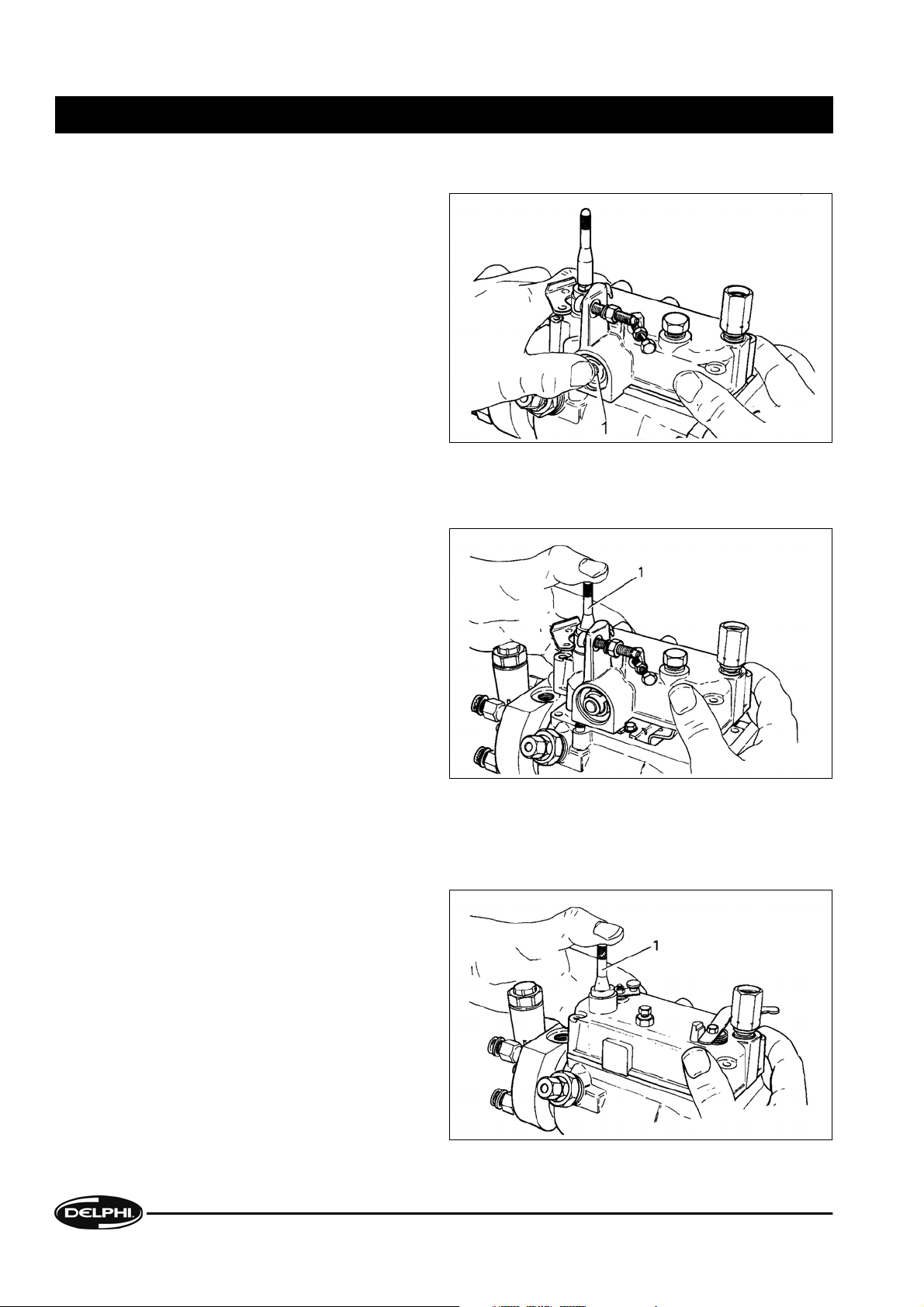
(iii) Disengaging the hydraulic excess fuel device
Position the pump so that the drive end is to the
right. Grip the governor cover firmly as shown;
depress and hold in the hydraulic excess fuel piston
(1) with the thumb, so as to disengage the fork in
the control bracket from the excess fuel pin. Lift the
governor cover sufficiently to release the excess
fuel pin from the fork and then release the excess
fuel piston.
(iv) Removing the governor cover
Pressing firmly on the protection sleeve (1) push the
throttle shaft down through the governor cover and
lift the complete cover assembly clear. Remove the
protection sleeve.
Remove and discard the O-ring and nylon ring, if
fitted, from the recess in the throttle shaft spigot.
B) Pumps with mechanical excess fuel
(i) Removing the governor cover
Fit a protection sleeve (1) to the throttle shaft.
Remove the four governor cover securing screws
and plain washers (as shown in
Section 2.2.7 (ii)).
Pressing firmly on the protection sleeve as shown.
push the throttle shaft down through the governor
cover and lift the complete cover assembly clear.
Remove the protection sleeve.
Note: When removing the governor cover, ensure
that the excess fuel lever does not damage the
governor link.
II DISMANTLING
DISMANTLING
2-14
DDNX117A(EN) - Issue 1 of 08/2008
© Delphi
Page 25
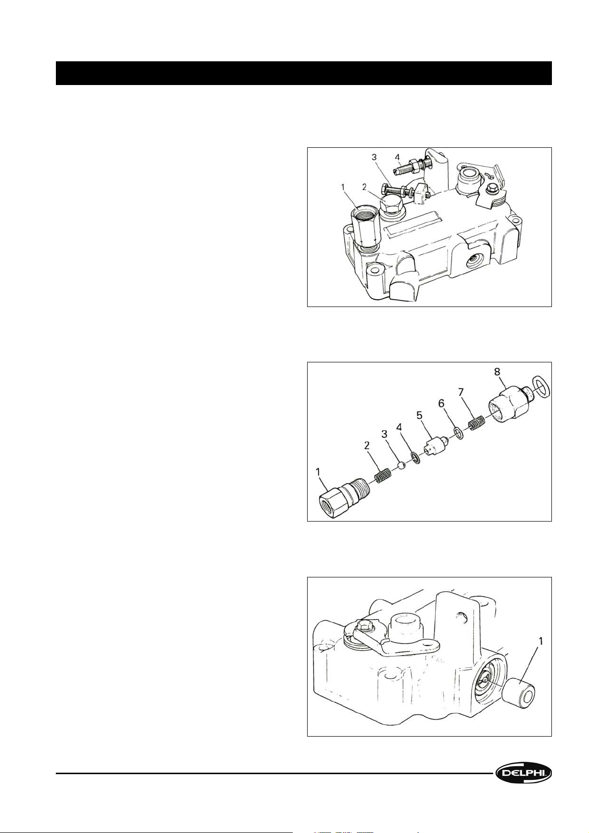
2.2.8 Dismantling the governor cover assembly
A) Removing the backleak connection or pressurising valve, vent screw and stop screws
Unscrew and remove the backleak connection (1) or
pressurising valve and the governor cover plug (2)
or vent screw; remove and discard the sealing
washer(s). Slacken and remove the idling stop
screw (3) and the throttle stop screw (4).
B) Dismantling the cambox pressurising valve
Clamp the pressurising valve body (8) in a softjawed vice. Unscrew the fuel connection (1). Tip out
the following components: spring (2), ball (3),
sealing washer (4), valve body (5), sealing washer
(6) and filter spring (7).
C) Dismantling the hydraulic excess fuel device
Remove the hydraulic excess fuel piston (1)
DISMANTLING II
DISMANTLING
DDNX117A(EN) - Issue 1 of 08/2008
2-15
© Delphi
Page 26

From inside the governor cover, use the excess fuel
piston (1) to push out the excess fuel assembly.
Separate the sleeve (2) and discard the O-ring (3).
Remove the external E-clip (4), spring (5) and pin
guide (6) from the excess fuel pin (7).
D) Removing the stop lever
Remove the bolt (2) or nut, whichever is fitted, and
the "star" and plain washers (3). Carefully lift off the
lever (4) and release the tension on the spring (1).
Remove the dust cover (5).
E) Removing the stop shaft
Push the stop shaft (1) down through the governor
cover. Remove and discard the O-rings.
Note: Some pumps may have additional levers,
e.g. idling. Slacken and remove the fixing nut or
bolt, washers, return spring and dust cap. Push the
shaft through the bore in the governor cover, and
discard the O-rings or seal. In the case of the sidemounted idling lever and shaft, remove the E-clip
and operating fork from the shaft and push the shaft
outwards through the governor cover.
II DISMANTLING
DISMANTLING
2-16
DDNX117A(EN) - Issue 1 of 08/2008
© Delphi
Page 27
2.2.9 Throttle shaft and governor spring
A) Dismantling the variable speed governor
Remove and discard the governor cover gasket (1).
Detach the main governor spring (5) from the
throttle shaft link (6) and the idling spring peg (2).
Remove the peg, idling spring (3) and ball seat (4)
from the governor control arm (8).
Note how many O-rings (7) are fitted !o the throttle
shaft; remove and discard them.
B) Dismantling the two-speed governor
Remove and discard the governor cover gasket (1).
Restrain the end plug (6) and remove the selflocking nut (2), spring guide (3), spring (4) and pivot
ball washer (5) from the spring pack (7). Detach the
spring pack from the control arm (9).
Note: Do not dismantle the spring pack and throttle
shaft or disturb the end plug relative to the spring
tube as these are factory preset; also, there is a fixed
idling spring on the governor arm.
Note how many O-rings (8) are fitted to the throttle
shaft; remove and discard them.
DISMANTLING II
DISMANTLING
DDNX117A(EN) - Issue 1 of 08/2008
2-17
© Delphi
Page 28

2.2.10 Control bracket and governor assembly
A) Disengaging the scroll link plate return spring
The return spring can be either a "coil" type or a coiled "hairpin" type.
(i) Coil-type spring
Very carefully grip the shoulder on the central pin
(1) with thin-nosed pliers and pull it away from the
spring stop (2) in the direction of the arrow,
compressing the spring. Carefully release the
spring tension and remove the spring and pin. If it
is difficult to grip the pin, carefully slacken the
spring stop screw and allow the stop to swing clear
of the pin.
CAUTION
The spring is under sufficient pressure to cause it to
fly away if it is not restrained.
(ii) Hairpin-type spring
Release the spring (1) from the peg (2) on the control
bracket (3). Remove the governor bracket screw (4),
which retains the link plate return spring assembly,
and remove the upper thrust washer (5), return
spring (6), spring collar (7), lower thrust washer (8)
and spacer (9).
II DISMANTLING
DISMANTLING
2-18
DDNX117A(EN) - Issue 1 of 08/2008
© Delphi
Page 29
B) Bell crank lever and locking tabs
Remove external circlip (2) and lift off the bell crank
lever (4).
With a suitable screwdriver, bend down the tabs on
the tab washers securing the three control bracket
screws (1), (5) and (7) and the bell crank post (3).
Unscrew and remove the screws from the governor
bracket (6) and discard the tab washers.
C) Governor control bracket, metering valve and transfer tube
Lift out the bracket (1), together with the control arm
assembly and the metering valve (2) from the pump
housing. Separate the bracket assembly from the
governor control arm.
Carefully remove the transfer tube (3) either from
the governor cover or the housing. Remove and
discard the O-rings (4). If the transfer tube is a
hollow pin pressed into the pump housing leave it
in situ, unless it is damaged, and discard the O-ring.
DISMANTLING II
DISMANTLING
DDNX117A(EN) - Issue 1 of 08/2008
2-19
© Delphi
Page 30

2.2.11 Governor control arm assembly and idle actuator
A) Dismantling the governor link assembly
(i) Single-spring link assembly
Unscrew and remove the governor linkage locknut
(1) and adjusting nut (2). Detach the washer (3) and
pivot ball washer (4). Withdraw the spring linkage
from the governor control arm (5) and remove the
washer (6), spring (7) and spring retainer (8) from
the link hook (9). Release the metering valve (10).
(ii) Three-spring link assembly
Hold the assembly in compression and unscrew the
locknut (1) and the linkage nut (2); remove the
washer (3) and pivot ball washer (4), from the
linkage hook (14).
Slowly release the compression of the springs and
disengage the hook from the governor control arm
(5). Remove the washer (6), spring (7), spacer (8),
washer (9) spring (10), spring retainer (11), spring
(12) and guide (13) from the hook. Release the
metering valve (15).
B) Removing the idle actuator
Use the special tool or a hexagon key to remove the
two socket-headed screws (1); remove the guide
bracket (2) and the idle actuator (3) from the pump
housing.
Note: Idle actuators operated by a lever mounted
in the top of the governor cover are slotted to
receive the eccentric pin on the idling shaft.
II DISMANTLING
DISMANTLING
2-20
DDNX117A(EN) - Issue 1 of 08/2008
© Delphi
Page 31

2.3 High Pressure Outlets, End Plate Assembly, Shut-Off Solenoid & Transfer Pump
2.3.1 High pressure outlets
A) Axial
Unscrew and remove each high pressure outlet (1).
Remove and discard the seating washer from the
bottom of each outlet bore. The pressurising valves,
if fitted, are factory-sealed units and cannot be
serviced. Delivery valves, if fitted, must be retained
in their matched pairs.
B) Radial with delivery valves
Remove all the nuts (2) securing the outlet
connections to the clamping plate (12), if fitted, and
remove the plate. Remove the banjo bolts (1) and
discard the washers (3). Place each outlet assembly
(4) in a soft-jawed vice, clamping at the banjo bolt
end (but
not across the sealing faces). Unscrew
and remove the delivery valve holder (11). Remove
the peg (10), spring (9), upper washer (8), valve (7),
body (6) and lower washer (5). Discard both sealing
washers.
DISMANTLING II
DISMANTLING
DDNX117A(EN) - Issue 1 of 08/2008
2-21
© Delphi
Page 32

C) Radial without delivery valves
Slacken and remove the connector clamping nuts
(2) and clamping plate (4), if fitted. Slacken and
remove the pressurising valves (1) or, alternatively,
the banjo bolts and discard the washers (3).
2.3.2 End plate assembly
A) Removing the end plate assembly
If fitted, slacken and remove the transfer pressure
relief valve (3). Discard the O-rings (1) and (2).
Slacken, but do not remove, the fuel inlet adaptor
(4).
Remove the four end plate screws (5) and the four
support bracket screws (8), if fitted.
Remove the end plate assembly (7) and pump
support bracket (6), if fitted.
B) Dismantling the end plate assembly
Remove the fuel inlet adaptor (1), followed by the
fuel inlet filter (3), spring (4), transfer pressure
adjuster (5), peg (6) and regulating spring (7),
regulating sleeve (8), piston (10), sealing washer (9)
and priming spring (11).
Discard the O-ring (2) or the copper washer, if fitted,
inlet filter and sealing washer.
Remove the sandwich plate (12), if of the "loose"
type. Some plates are bonded to the end plate and
are not removable.
Note: In later pumps the peg and spring are
combined into one assembly.
II DISMANTLING
DISMANTLING
2-22
DDNX117A(EN) - Issue 1 of 08/2008
© Delphi
Page 33

2.3.3 Shut-off solenoid
Unscrew and remove the shut-off solenoid
assembly (1). Tip out the plunger (2) and spring (3):
remove and discard the O-ring (4) from the solenoid
body and remove the terminal nut (6) and washer
(5). Some pumps may have the solenoid replaced
by a plug (7). If so, remove the plug and discard the
O-ring.
2.3.4 Transfer pump
A) Removing the transfer pump components
Remove the transfer pump sealing ring (1).
Carefully lift out the liner (2) together with the
transfer pump blades (3) (and springs, if steel
blades are fitted).
Note: Incorrect reassembly of the liner could
seriously affect transfer pump performance and
may damage the blades.
B) Slackening the transfer pump rotor
Hold the drive shaft using a suitable tommy-bar (2)
inserted through the governor arm aperture and
into the hole in the drive shaft. Use the special tool
(1) to slacken the transfer pump rotor in the
direction of rotation shown by the arrow (3)
on the nameplate. Do not remove the transfer
rotor at this stage.
Note: Left-handed transfer rotors are marked with
an arrow on the end face showing the direction in
which to unscrew the rotor.
DISMANTLING II
DISMANTLING
DDNX117A(EN) - Issue 1 of 08/2008
2-23
© Delphi
Page 34

2.4 Advance Device, Latch Valve And Rotor Vent Switch Valve
2.4.1 Dismantling the advance device
A) Speed advance (plus start retard, if fitted)
Invert the pump so that the advance device is
uppermost.
Remove the spring cap advance gauge access
screw (1) and discard the sealing washer (2).
Unscrew the advance piston spring cap (3), shim(s)
(5) and main advance spring(s) (6) & (7). Unscrew
the piston plug (9); remove and discard the O-rings
(4) and (8).
If fitted, remove the spring plate (12), circlip (11),
and retard spring (10).
B) Speed advance, start retard & manual idle advance (spring end)
Note: This particular type of advance device must
be removed from the pump prior to dismantling,
therefore it will be necessary to refer to
Section
2.4.2
. However, slacken the plug (1) and cap (16)
before removing the advance assembly.
Remove the piston plug (1), discard its O-ring (2)
and remove the advance piston (3).
Hold nut (12) with a suitable thin spanner and
slacken the locknut (11). From the pressure side of
the advance piston bore, insert a screwdriver into
the slot in the inner end of the spindle (5); unscrew
and remove the nut and locknut.
Holding both components firmly together, remove the manual idling advance lever (13) and detent plate (15).
Separate the detent plate from the lever; take care not to lose the three steel balls (14). Push the spindle through
the cap.
Clamp the advance housing in a soft-jawed vice; remove the cap (16) and anchor plate (17). Remove the phasing
shim (18) and anchor plate from the cap. Remove the shims (20) from the cap and discard the cap O-ring (19).
Remove the spindle and advance spring assembly. Detach the following from the spindle: advance spring (10),
spring (8), O-rings (9) (which must be discarded), washer (7), spring plunger (6) and retard spring (4).
II DISMANTLING
DISMANTLING
2-24
DDNX117A(EN) - Issue 1 of 08/2008
© Delphi
Page 35

C) Start retard, speed advance & manual cold idle advance (pressure end)
Unscrew and remove the advance gauge access
screw (1) from the advance spring cap (3) and
discard the seal (2). Unscrew the following: spring
cap, shim(s) (5), main advance springs (6), spring
plate (7), circlip (8) and retard spring (9).
Remove and discard the O-ring (4).
Remove and discard the E-clip (18) from the
housing; remove the washer (17) and splined lever
(16) from the shaft (12).
Unscrew and remove the housing assembly (15).
The cam (11) may be retained in the advance
housing. If so, remove it and the internal circlip (10).
Remove the shaft from its housing; remove and
discard both O-rings (13) and (14) from the shaft.
D) Servo-controlled advance piston with mechanical light load advance, cold idle advance and speed advance
(i) Light load advance
Remove the operating plunger (2) and the servo
spring (4). Tip out the shim(s) (3) from the plunger
and remove the circlip (1). Using an appropriate
lever, remove and discard the oil seal (5) from the
spring cap (6). Unscrew the spring cap and discard
the O-ring (7).
(ii) Cold idle advance
Whilst holding the lever (9), slacken and remove the
self-locking nut (8). Remove the lever from the
splined shaft.
Remove the plug assembly (10). Push the shaft and
piston assembly (12) through the plug. Remove and
discard the O-rings (11) from the shaft, the two Orings (13) and (15) and two split nylon rings (14) and
(16) from the plug.
Note: On later pumps the shaft, piston and pin are
a loose assembly and should be dismantled for
examination.
DISMANTLING II
DISMANTLING
DDNX117A(EN) - Issue 1 of 08/2008
2-25
© Delphi
Page 36

2.4.2 Advance housing
A) Removing the advance housing
Remove the advance housing cap-nut (1); remove
and discard the sealing washer (2).
Slacken the head locating fitting (9) or transfer
pressure damper (7), whichever is fitted, no more
than three turns. Tap the advance housing (4) with
a soft-faced mallet to free it from the gasket (3).
Remove the head locating fitting and the advance
housing together, taking care not to lose the lockoff bail (6), if fitted.
Note: In the case of a head locating fitting with a
captive lock-off ball do not disturb the slotted screw
in the head of the fitting.
Remove and discard the O-rings (5) or (8), and the nylon ring, if fitted, from the head locating fitting or the damper;
discard the gasket.
B) Removing the advance piston
Remove the advance piston (1). in the case of the
servo advance device, remove the circlip (5) and
washer (4) retaining the spring pin (3). Remove the
servo valve (2). Do not disturb the lock-off ball
retaining-screw in the head of the advance piston;
this is a factory sealed assembly.
Note: The advance housing, advance piston and
servo valve are a mated assembly and cannot be
replaced individually.
II DISMANTLING
DISMANTLING
2-26
DDNX117A(EN) - Issue 1 of 08/2008
© Delphi
Page 37

C) Removing the cam screw
Fit the correct adaptor (1) to the cam screw (2).
Using a suitable socket and tommy-bar or torque
wrench, slacken the cam screw one complete turn.
The cam ring will almost certainly become stuck in
the pump housing. To free the cam ring remove the
tommy-bar and socket from the adaptor and,
ensuring that the adaptor remains in place on the
cam screw, tap the adaptor sideways with a softfaced mallet; remove the cam screw.
2.4.3 Latch valve
A) Removing the latch valve
Slacken, in turn, the locknut (1), sleeve nut (2) and
body screw (3). Hold the locknut and slacken the
adjuster (4). Note the position of the latch valve in
the hydraulic head; remove the complete valve
assembly and discard the sealing washer (5).
B) Dismantling the latch valve
Remove the adjuster (1) and locknut (2) from the
sleeve nut (4). Separate the adjuster from the locknut; remove and discard the square-section rubber
washer (3). Tip out the spring (6) and remove the
sleeve nut from the body screw (8); remove and
discard the sleeve nut O-ring (5).
Tip out the valve (7) from the body screw. Remove
and discard the two O-rings (9) from the body
screw. If the filter (10) is damaged or blocked, use a
suitable piece of rod to push it out from within the
valve body.
Note: Some pumps have "differential" latch valves.
These valves are hollow and have a control orifice
in the side of the valve stem.
DISMANTLING II
DISMANTLING
DDNX117A(EN) - Issue 1 of 08/2008
2-27
© Delphi
Page 38

2.4.4 Rotor vent switch valve
While the valve assembly (1) is still secure in the
hydraulic head, slacken the spring plug (2) in the
body (6). Unscrew and remove the valve assembly
from the hydraulic head. Discard the two backing
washers (7) and (9), the two O-rings (8) and the seal
(10). Remove the plug, discard its O-ring (3), and
remove the spring (4) and valve (5).
Note the position of the switch valve assembly in
the hydraulic head.
Note: (1) If both valves are specified, take care not
to mix the valve pins as they are the same nominal
diameter.
Note: (2) The valves are matched to their bodies and must be kept assembled.
Note: (3) If a head locking screw is specified in place of the rotor vent switch valve, remove the screw and discard
the sealing washer.
2.5 Hydraulic Head And Drive Shaft Assembly
2.5.1 Releasing the hydraulic head
Grip the hydraulic head as shown and, whilst
keeping it straight, pull and twist it out of the pump
housing just far enough to expose the large O-ring
(1). Leave the head in this position.
II DISMANTLING
DISMANTLING
2-28
DDNX117A(EN) - Issue 1 of 08/2008
© Delphi
Page 39

2.5.2 Removing the drive shaft nut, key and thrust washer
A) Removing the drive shaft nut and key
If still fitted, remove the hub securing nut and
washer. Using either a suitable pair of side cutters
or a small screwdriver carefully lever out the
Woodruff key (1). If the alternative pin is fitted it
must be removed. If fitted, remove the circlip (2) and
the thrust washer (3).
B) Removing the outer oil seal, drive shaft circlip and thrust washer (if fitted)
Lever out the outer seal, avoiding damage to the
seal bore in the pump housing. Remove the circlip
(4) and thrust washer (3) and then ball (2) from the
indent (1) in the shaft. The inner seal will be
removed after withdrawal of the drive shaft.
C) Removing the pump housing from the head and drive shaft assembly
Remove the pump from the Hydraclamp and place
it on the bench with the hydraulic head downwards.
Press down on the end of the drive shaft and then
lift the housing off the head and drive shaft
assembly.
DISMANTLING II
DISMANTLING
DDNX117A(EN) - Issue 1 of 08/2008
2-29
© Delphi
Page 40

D) Removing the drive shaft assembly
Set the Hydraclamp plate horizontal. Grasp the cam
ring in one hand and the drive shaft in the other. Lift
the assembly off the hydraulic head, invert it, and
place it upright into the Hydraclamp plate as shown.
If the outer scroll plate (1) has adhered to the head,
remove it and place it with the other loose
components.
Place a plunger retaining cap (2) over the hydraulic
head rotor and discard the large O-ring (3).
E) Removing the cam ring, scroll plate, rollers and shoes
Lift off the cam ring (2), scroll plate (3) and rollers
and shoes (1) and (5) (ensuring that they remain in
their matched pairs) and the inner bearing (4).
F) Removing the drive shaft and governor weights
Lift out the drive shaft. Lift out the thrust sleeve (1),
weights (3) and the thrust washer (2) from the
weight cage (4).
II DISMANTLING
DISMANTLING
2-30
DDNX117A(EN) - Issue 1 of 08/2008
© Delphi
Page 41

2.5.3 Dismantling the shaft assembly
A) Remove the roller cage
Grip the drive shaft lightly in a soft-jawed vice taking
care to avoid any damage to the surface of the
shaft. Do not over-tighten the vice. Use a
suitable Torx screw bit and adaptor (1) to remove
the four catch plate screws (2). Remove the catch
plate (3) and shoe plate (4).
B) Slackening the support block screws
Invert the drive shaft and clamp it (across the gaps
in the large diameter, as shown) in the vice
fitted with soft jaws.
Note: Before slackening the support block screws
of drive shafts with internal timing discs, mark the
position of the disc (1) in relation to the drive shaft
using an indelible felt-tip marker or a suitable
electric etching tool as shown at (3). This will ensure
that the disc is correctly aligned during reassembly.
Using an extended Torx screw adaptor (2) , slacken
ail the support block screws (4).
C) Removing the support blocks and timing disc
Remove the drive shaft from the vice and remove
the support block screws (1), washers, timing disc,
if fitted (see previous illustration), and support
blocks (2).
Note: In the case of two-plunger pumps, mark the
position of the shorter support block with a felt-tip
pen or etcher; this controls the position of the offset
tang on the hydraulic head rotor and hence the
position of the delivery port in relation to the drive
shaft keyway.
DISMANTLING II
DISMANTLING
DDNX117A(EN) - Issue 1 of 08/2008
2-31
© Delphi
Page 42

2.5.4 Pump housing
A) Removing the oil seal
Note the direction of the seal lip (i.e. facing inwards
or outwards). Use the specified tool (1) to lever out
the seal, which must be discarded, taking care to
avoid damage to the seal bore in the housing.
In the case of twin seals, the outer seal, circlip,
spacer and ball were removed prior to removal of
the housing from the shaft . The inner seal must
now be removed, again avoiding damage to the
seal bore in the housing.
B) Removing the advance housing stud
Examine the advance housing stud (1). There are
two methods for fixing the stud in the pump
housing: one stud type has a threaded section, the
end of which will be visible inside the pump
housing; the other has a splined section and a large
diameter head, which can also be seen inside the
pump housing.
If the stud is damaged, the threaded type may be
removed with the use of a suitable stud extraction
tool If the stud is of the splined type the complete
pump housing must be replaced.
II DISMANTLING
DISMANTLING
2-32
DDNX117A(EN) - Issue 1 of 08/2008
© Delphi
Page 43

2.6 Removal Of The Head And Rotor Only
2.6.1 Preparation
Mount the pump in a Hydraclamp with its axis
horizontal. Remove all of the high pressure outlets
(1) whether axial, as shown, or radial (as described
in
Section 2.3.1). Remove the end plate assembly
(2) (as described in
Section 2.3.2) and blanking plug
(3) or stop solenoid. Discard all disturbed sealing
washers.
Remove the governor cover (4) (as described in
Section 2.2.7); disconnect the throttle spindle from
the governor spring assembly. Remove all the
governor control bracket screws, lift the control
bracket assembly and withdraw the metering valve
from the hydraulic head.
2.6.2 Transfer pump and head fittings
Remove and discard the end plate seal. Note the
position of the fuel outlet slot in the end face of the
liner. Remove the liner, blades and springs, if fitted.
Hold the drive shaft with a suitable tommy-bar (3)
through the transverse hole in the shaft and use the
special adaptor tool (4) to slacken, but not remove,
the transfer pump rotor. The rotor must be
unscrewed in the direction of pump rotation
as shown on the pump name plate.
Note: Left-handed transfer rotors are marked with
an arrow on the end face showing the direction in
which to unscrew the rotor.
Slacken and remove the three head fixings: head
locating fitting (5), latch valve (1) and rotor vent
switch valve (2) or head locking screw (whichever
is fitted). Discard all seals. Do not disturb the
advance device, which will remain supported by the
stud and nut.
DISMANTLING II
DISMANTLING
DDNX117A(EN) - Issue 1 of 08/2008
2-33
© Delphi
Page 44

2.6.3 Releasing the hydraulic head
Hold the head as shown and withdraw it sufficiently
from the pump housing by twisting and pulling it to
just expose the O-ring (1). Rotate the Hydraclamp
to place the pump axis vertical with the hydraulic
head uppermost and remove the head from the
housing.
Ensure that the plungers do not fall out of their
bores by keeping the head vertical until a plunger
retaining cap has been placed over the exposed
rotor end.
II DISMANTLING
DISMANTLING
2-34
DDNX117A(EN) - Issue 1 of 08/2008
© Delphi
Page 45

3.1 Cleaning
If water contamination is suspected, carry out an initial examination of all internal components before attempting any
further cleaning. Clean out all passageways in the head and rotor by flushing out with clean test oil.
3.2 General
3.2.1 Mated and matched assemblies
The hydraulic head and rotor should be separated and examined; they should be re-mated immediately after
examination and immersed in a covered bath of clean test oil until required for reassembly into the pump.
The following groups are matched and must be kept in their sets:
1. Rollers and shoes
2. Delivery valves and seats
3. Advance housing, piston(s) and servo valve
4. Latch valve and body
5. Rotor vent switch valve and body
6. Cam ring and scroll plates
7. Stop solenoid plunger and body
8. Cold idle advance body and piston
If any part is considered to be unfit for further service, the whole assembly must be replaced.
Note: The pump housing drive shaft bush is not a service repair item; if the bearing is worn, the housing must
be replaced.
3.2.2 Examination and replacement
Check all components for corrosion, wear, or damage. Under service workshop conditions it is not feasible to test
individual parts or subassemblies to determine their suitability for further service. Close examination of the areas
vulnerable to damage, and interpretation of pre-test results, should indicate the condition of parts.
A) Corrosion
Check for signs of corrosion or water ingress (rust or staining) damage to machined surfaces. These include the
pump housing, drive shaft. rear bearing, hydraulic head bore, cam ring, scroll plates, end plate, valves and auto
advance device.
B) Wear
Inspect drive shaft splines and associated parts for wear or damage. If excessive end-float or radial play was
detected prior to pump strip down, examine the drive shaft thrust washer and housing bearing thrust face for
wear.
C) Damage
Inspect all parts for damage or bending due to abuse, especially external levers and controls.
3.2.3 Seals
Replace all gaskets i.e. the governor cover, advance device and inspection cover, as well as all seals. Note that
overhaul kits may not include drive shaft seals, which are stocked as separate items.
When fitting new O-rings and oil seals, care must be taken to use protection caps to avoid damage to the seals.
Internal seals must be dipped in clean test oil prior to being assembled. External seals must be lightly coated with
grease. Where possible, inspect seals for small cuts after assembly.
COMPONENT INSPECTION AND RENEWAL III
COMPONENT INSPECTION AND RENEWAL
DDNX117A(EN) - Issue 1 of 08/2008
3-35
© Delphi
Page 46

3.3 Details
3.3.1 Hydraulic head rotor
Withdraw the rotor from the hydraulic head. Examine the running surface very closely for signs of erosion,
particularly the area around the delivery port. If severe erosion is evident, the head and rotor assembly must be
replaced.
3.3.2 Hydraulic head plungers
If damage to the plungers is suspected, carefully separate the plungers from the rotor, one at a time, and inspect
them for scoring or other damage. Clean each plunger with test oil and immediately replace it very carefully in
its original bore, the same way round.
The recommended plastic retainer or short lengths of clean nitrile rubber tubing should be used to retain the
plungers in their bores. Replace the hydraulic head if the plungers show severe scratching.
Note: If the plungers are stepped, they are fitted with the smaller diameter in towards the centre of the rotor. If
they are of different lengths the two longer plungers are fitted in line with the axis of the rotor delivery port.
3.3.3 Cam ring and scroll plates
Inspect the running surface of the cam ring and scroll plates for signs of breakdown of the leading face or apex
of the profile. If there are significant signs of pitting or "smearing" they must be replaced as a set. Smearing is the
result of failure of the surface due to abrasion or overloading, which may be due to excessive hydraulic pressure
(possibly caused by nozzle blockage).
3.3.4 Rollers and shoes
Inspect rollers and shoes for damage. Pay particular attention to the condition of the contact surfaces and check
that the rollers rotate freely in their shoes. If the cam ring has failed, the rollers and shoes may also have been
severely damaged. If satisfactory, rollers must be replaced in their original shoes.
3.3.5 Transfer pump
Check blades for chips, scores or breakages. Blades may be of carbon, resin-bonded carbon, or sintered steel.
Resin-bonded blades have an identification groove in the base of the central slot. Carbon blades have no groove.
Blades must be replaced in sets and must be of the same type as the originals. Examine the transfer pump rotor
for wear or damage.
3.3.6 End plate and transfer pump liner
Examine the inner face of the end plate for wear. Replace it if there is any significant scoring. If a separate sandwich
plate is fitted. and it is scored or worn, it must be replaced and not reversed.
Examine the liner for corrosion or scoring and replace it if there are any signs of damage.
3.3.7 Control valves
Check all control valves for wear or scoring. Examine the metering valve for "stepping" of the control slot edges
and at the point where it enters the bore in the hydraulic head. Check that the valve and the governor link pin are
securely fixed in the bar. Check the regulating valve, latch valve and rotor vent switch valve for damage or
corrosion and blockage of orifices.
III COMPONENT INSPECTION AND RENEWAL
COMPONENT INSPECTION AND RENEWAL
3-36
DDNX117A(EN) - Issue 1 of 08/2008
© Delphi
Page 47

3.3.8 Delivery valves and cambox pressurising valves
Check for defects in delivery valve assemblies. If movement of the valve can be detected when shaken, the spring
may have collapsed, in which case it should be replaced. lnspect the cambox pressurising valve (if fitted) for wear
and damage, particularly the spring, valve and filter spring.
3.3.9 High pressure outlet pressurising valves
A) Outlets on "radial" hydraulic heads
(i) "Piston" type:
The outer end of the rollpin should be either flush with the end of the banjo bolt or outlet connector body, or
recessed by no more than 0.8rnm. Test the freedom of the valve by pushing a thin rod through the centre of the
rollpin.
(ii)"Ball" type:
In the 7139-183 series, the balls should be either flush with the outer face of the valve body or protrude by no
more than 1.2mm. Examine the balls for damage or signs of corrosion.
Use a suitable piece of brass rod to push each ball into its holder against the spring to check for freedom of
movement. If one assembly is faulty, replace the whole set.
B) Outlets on "axial" hydraulic heads
Only the "ball" type of pressurising valve is used and, in the 7185-022 series, the balls should be either flush with
the outer face of the valve body or protrude by no more than 0.5mm (see Service Instruction Note
D014 for full
details of both types of valve).
3.3.10 Springs
Look for distorted or fractured springs. Very carefully examine the areas of contact with adjoining components
(spring pegs, throttle shaft links etc).
Check that all springs specified in the Parts List for the pump are present.
3.3.11 Fittings and threads
Check all screws and nuts for damage. Check the cam advance screw flats, which may have been damaged by
careless application of the high tightening torque.
Check all threads for damage, especially on the transfer and distributor rotors, hydraulic head, cam advance screw
hole, studs, fuel inlet and return and high pressure outlet connections.
3.3.12 Linkages
lnspect all mechanical governor linkages, shafts, pivot pins and arms for wear, cracks or scoring of their mating
surfaces.
Examine the cold idle advance spring-loaded plastic link for breakage.
3.3.13 Control shafts
Examine control shafts and their associated bores in the governor cover for distortion, wear, looseness of joints
or elongation of spring anchor holes. The items in this group are; the excess fuel shaft, idling and manual idling
advance shafts, speed control, manual stop, and their associated levers and linkages.
COMPONENT INSPECTION AND RENEWAL III
COMPONENT INSPECTION AND RENEWAL
DDNX117A(EN) - Issue 1 of 08/2008
3-37
© Delphi
Page 48

3.3.14 Drive shaft and associated component
lnspect the shaft for wear or damage, especially where the oil seal(s) contacts the shaft. Check splines and keyways
for cracks or chipping.
Examine the thrust surfaces on the inner face of the pump housing and the weight cage for damage or scoring.
Examine the governor weight cage and weights for wear, cracks, or damage. Ensure that the correct number and
type of governor weights are fitted.
3.3.15 Advance device
Examine the components for corrosion. If water has been present in the fuel, it will tend to settle in the advance
housing.
Check that pistons move freely.
3.3.16 Levers and external controls
Examine all levers for excessive wear at contact points and for cracks.
Examine the HSDI light load advance cam for excessive wear.
3.3.17 Pump housing
Examine the housing for damage, especially to the sealing surfaces. II the bearing is unfit for further service, the
housing must be replaced.
3.3.18 Orifices
Examine all orifices for blockage and carefully clear any obstruction with dry compressed air.
3.3.19 Electrical connections
Ensure that all electrical solenoid parts are clean, especially the connection(s), and that the plunger is free in its
bore. Check that the flexible valve seat is in good condition, with no pitting or other damage.
Note: if any fault is apparent in the stop solenoid assembly, the whole unit must be replaced as the plunger is
matched to the body.
3.3.20 Oversize metering valves
Some DPS pumps are fitted with hydraulic heads having an oversize metering valve bore and an oversize metering
valve to suit. Pumps fitted with such heads have the number 6.375 etched between the outlet connections adjacent
to the metering valve bore. The appropriate metering valve part number is given in the Parts List, as "Size B':
III COMPONENT INSPECTION AND RENEWAL
COMPONENT INSPECTION AND RENEWAL
3-38
DDNX117A(EN) - Issue 1 of 08/2008
© Delphi
Page 49

4.1 Preparation
Before using thread locking compound, if specified,
ensure that the mating surfaces are completely oil free
and dry.
When reassembling pumps, it is important to use the
correct overhaul kit. The relevant kit number can be
found in the Service Parts List.
Lightly lubricate all flexible seals and O-rings with clean
test oil and external seals with grease before assembly
in their respective positions. Always use the correct
protection cap when fitting new O-rings.
Refer to the relevant Test Plan for details of special build
items and any initial setting instructions.
Refer to
Section 6 for all special tools, protection caps
and torque values.
The direction of rotation of the pump is as viewed from
the drive end.
4.2 Drive Shaft Assembly, Governor Weight Cage, Pump Housing, Head And Rotor
4.2.1 Drive shaft assembly
A) Roller shoe spacers and timing disc
Insert the spacers (1) into the recesses in the drive
shaft (2). In the case of two-plunger pumps, place
the short spacer in the position noted during
dismantling. Secure each spacer with the
appropriate Torx screw (3) and washer.
Note: If an internal timing disc is specified, fit the
disc (4) prior to inserting the spacer screws. Ensure
that the marks made on the disc and the drive shaft
during dismantling are in line. If the disc (or the
shaft) is to be replaced, transfer the mark(s) to the
new component.
REASSEMBLY IV
REASSEMBLY
DDNX117A(EN) - Issue 1 of 08/2008
4-39
© Delphi
Page 50

B) Tightening the torx screws
Secure the rotor end of the drive shaft in a softjawed vice and, using the appropriate Torx adaptor
(1), tighten each screw progressively to the
specified torque value.
Note: It is essential that the drive shaft is clamped
across the slots as shown and that only the
minimum necessary clamping force is imposed
upon the shaft, to avoid distortion.
C) Roller shoe plate and roller catch plate
Carefully mount the drive shaft (1) in a vice fitted
with soft jaws and with a "Tommy bar" through the
cross-hole to resist the screw tightening torque as
shown. Fit the roller shoe plate (2), followed by the
roller catch plate (3), to the drive shaft. Secure the
plates using the four screws (4), tightened to the
specified torque value with the appropriate "Torx"
adaptor (5).
4.2.2 Governor weight cage and drive shaft assembly
A) Weight cage assembly
Place the weight cage (1) on the Hydraclamp
mounting plate.
Fit the fly-weights (2) into the weight cage. If less
than six flyweights are specified, they must be
placed into the weight cage symmetrically. The
"Toes" of the flyweights should be at the bottom of
the cage, facing inwards. Fit the thrust washer (3),
making sure that it rests on the toes of the
flyweights, and then insert the thrust sleeve (4) with
its flat end against the thrust washer.
IV REASSEMBLY
REASSEMBLY
4-40
DDNX117A(EN) - Issue 1 of 08/2008
© Delphi
Page 51

B) Assembly of the drive shaft to the weight cage
Fit the drive shaft assembly (1) through the thrust
sleeve (2) and the weight cage (3).
4.2.3 Inner bearing, scroll plates, and cam ring
A) Fitting of the inner bearing
Fit the inner bearing (1) to the drive shaft assembly
with the scroll plate recess (2) uppermost.
B) Fitting the rollers and shoes to the drive shaft
Fit the roller and shoe assemblies (1), (2) and (3) to
the drive shaft, ensuring that the long shoe (4) (fitted
into the slot without the shoe spacer) has its
lubrication slot (5) facing towards the drive end of
the pump.
Note: Two-plunger pumps have shoes of equal
lenght, each with a lubrication slot (5) which must
be fitted facing the drive end.
REASSEMBLY IV
REASSEMBLY
DDNX117A(EN) - Issue 1 of 08/2008
4-41
© Delphi
Page 52

C) Fitting the scroll plate to the inner bearing
Fit a scroll plate (1) into the recess of the inner
bearing, ensuring that the direction of the arrow (2)
matches the direction of rotation on the pump name
plate. The slot (3) in the scroll plate must be aligned
with the centre of the wide access slot (4) in the drive
shaft inner bearing.
D) Fitting the cam ring
Fit the cam ring (1), ensuring that the direction of
the arrow (2) matches that on the name plate label.
Ensure that the cam screw hole (3) lines up with the
tapered clearance slot (4) on the drive shaft inner
bearing.
The slot, in turn, should be aligned with the gap
between any two pockets in the weight cage. This
is so that the assembly will not foul the head of the
advance device stud when the pump housing is
fitted over the drive shaft.
E) Fitting the rear scroll plate
Fit the rear scroll plate (1), ensuring that the
direction of the arrow (2) matches that on the name
plate label, and that the slot (3) aligns with the slot
in the front scroll plate and the centre of the wide
access slot (4) in the drive shaft inner bearings.
IV REASSEMBLY
REASSEMBLY
4-42
DDNX117A(EN) - Issue 1 of 08/2008
© Delphi
Page 53

4.2.4 Hydraulic head rotor plug
Remove the distributor rotor from the head and
mount it in the special tool (1), in a vice. If the rotor
plug (2) is loose, remove it, clean and degrease it
and carefully smear the threads with "Araldite"
AV100 resin mixed with hardener HV100 in the
recommended proportions. Refit the plug to the
rotor, using a new seal washer. Use the special
hexagon key (3) to tighten the plug to the specified
torque.
Refit the rotor to the hydraulic head, ensuring that
no oil reaches the plug and leave to one side until
the recommended curing time has passed.
4.2.5 Assembly of the drive shaft to the hydraulic head
A) Transfer pump rotor and outer scroll plate
Screw the transfer pump rotor into the distributor
rotor and leave it finger-tight. Place the hydraulic
head on the bench with the transfer pump rotor
downwards.
Fit a new O-ring (1) to the head groove.
Lift the rear scroll plate off the cam ring and place
it, inverted, in the recess (2) in the head; this ensures
that the scroll plate is correctly installed with
respect to pump rotation. Remove the plunger
retaining clip (3).
B) Fitting the drive shaft to the head
Align the hydraulic head drive tang with the drive
shaft slot. Lift the drive shaft assembly from the
Hydraclamp; invert the assembly, ensuring that it
remains pushed together, and place it on to the
hydraulic head.
If necessary, rotate the drive shaft relative to the
rotor to engage the rotor tang with the drive shaft
slot. The metering valve bore (1), the two scroll plate
slots (2) and the wide access slot (3) in the drive
shaft inner bearing should all be in line.
REASSEMBLY IV
REASSEMBLY
DDNX117A(EN) - Issue 1 of 08/2008
4-43
© Delphi
Page 54

C) Checking component alignment
On the other side of the assembly a gap in the
weight cage (1) should be in alignment with the
drive shaft inner bearing tapered clearance slot (2).
the hole for the cam advance screw (3) and the head
locating bore (4) in the hydraulic head.
4.2.6 Housing
If the housing stud (1) has been removed, fit a new
stud.
Mount the housing in the Hydraclamp and use the
dome nut (3), together with a temporary 5/16 24
UNF lock-nut (2), to tighten the stud to the specified
torque. The lock-nut should be no more than 5mm
thick, to allow sufficient thread engagement for the
dome nut.
Note: If end float is controlled by an external shim
washer which abuts the pump housing spigot, the
oil seal(s) must be installed prior to fitment of the
drive shaft. (see
section 4.2.9).
Remove the housing from the Hydraclamp.
4.2.7 Fitting the pump housing to the drive shaft and hydraulic head
A) Fitting the housing to the internal components
Lightly lubricate the inside of the pump housing
with clean test oil and carefully lower it onto the
assembled drive shaft until it contacts the hydraulic
head O-ring; avoid excessive downward pressure.
IV REASSEMBLY
REASSEMBLY
4-44
DDNX117A(EN) - Issue 1 of 08/2008
© Delphi
Page 55

B) Mounting the assembly on the Hydraclamp
Position the Hydraclamp so that the mounting plate
(1) is horizontal; keep the complete assembly
together, invert it, place it onto the mounting plate
and secure it with the three clamping screws and
washers (2).
C) Alignment of the drive shaft and rotor
Position the pump horizontally. Lubricate the
hydraulic head O-ring with clean test oil and, using
a twisting action, push the head firmly into the
housing until it is fully engaged.
Note: If the hydraulic head will not move axially,
the rotor drive tang has probably become
disengaged. Slight twisting of the drive shaft and
the transfer pump rotor relative to each other will
re-align the drive tang and the slot in the drive shaft.
Check that the transfer pump rotor is flush with the
end face of the hydraulic head.
4.2.8 Transfer pump rotor
Insert a suitable tommy-bar (1) through the
governor weight cage aperture into the hole in the
drive shaft to prevent the drive shaft from rotating.
Fit the transfer pump adaptor (2) to the transfer
pump rotor and tighten the rotor to the specified
torque value.
Temporarily fit the transfer pump blades to the rotor
to check that they are free to move within their slots.
If they are tight, unscrew the rotor, check that the
threads and blades are clean and undamaged. Refit
and tighten the rotor. If the blades are still tight,
replace the rotor.
REASSEMBLY IV
REASSEMBLY
DDNX117A(EN) - Issue 1 of 08/2008
4-45
© Delphi
Page 56

4.2.9 Drive shaft oil seals
Note: If end float is controlled by a shim washer fitted in the seal bore and abutting the inner face of the pump
housing, the drive shaft, ball, shim and circlip must be fitted and end float checked and corrected by the use of
alternative shims before the seals are fitted See also the note in
section 4.2.7
A) Single oil seal
The drive shaft seal punch kit includes the seal
protection cap (1). Fit the cap to the drive shaft.
Moisten a new oil seal (2) with clean test oil, ensure
that the seal is the correct way round as noted
during dismantling and use the punch (3) and a hide
(or rubber) mallet to drive the seal fully into the
recess in the pump housing. Remove the protection
cap. The outer face of the oil seal should be just
below that of the pump housing (4).
Fit the thrust washer (5) and circlip (6) to the drive
shaft.
B) Double oil seal
Use the double oil seal punch kit to fit each seal in turn to the housing recess. Ensure that the seals face the
direction noted during dismantling. When specified, fit the circlip into the pump housing groove between the
seals.
C) Internal circlip
Position the shaft so that the recess (1) is
uppermost. Fit the ball (2) to the recess and align
the notch in the thrust washer (3) with the ball. Fit
the washer with the grooves facing the pump
housing. The notch should retain the ball.
Fit the circlip (4) into the groove and position the
gap in the circlip either side of the ball.
Check drive shaft end float and adjust as necessary
with the appropriate shims.
IV REASSEMBLY
REASSEMBLY
4-46
DDNX117A(EN) - Issue 1 of 08/2008
© Delphi
Page 57

4.2.10 Checking end-float and radial play
Note: End-float may be measured with or without the hydraulic head fitted to the pump housing; however, the
Inner bearing must be in position before radial play is measured.
A) End float
Fit the appropriate adaptor (1) to the drive shaft
thread. Screw in the dial gauge holder (4), and fit
the dial gauge (3). Adjust the gauge pin to contact
the machined face of the pump housing (2).
Push the drive shaft inwards and set the dial gauge
to zero. Pull the drive shaft outwards and note the
maximum gauge reading. End-float should be
between 0.05mm and 0.2mm. If it is outside that
tolerance, correct it by the use of alternative shims.
B) Radial play
Note: If the original housing and shaft are to be
used and radial play at the main bearing was found
to be within the limits stated below, it should not be
necessary to measure radial play at this stage. If
either item has been replaced play must be
measured.
With the pump and dial gauge (1) mounted rigidly
relative to each other adjust the gauge pin to bear
against the drive shaft (2). Push the shaft radially
towards the gauge and set the gauge to zero. Pull
the shaft radially to the opposite extreme and
record the gauge movement.
Repeat the readings with the gauge repositioned as
shown at (3) and (4). Do not rotate the drive
shaft. Reject the housing if either the maximum
play or the difference between the measurements
exceed the figures below.
Belt drive type: Max. play = 0.22mm, Max. difference = 0.1mm
Gear or hub drive type: Max. play = 0.27mm, Max. difference = 0.2mm
REASSEMBLY IV
REASSEMBLY
DDNX117A(EN) - Issue 1 of 08/2008
4-47
© Delphi
Page 58

4.2.11 Fitting the drive shaft key or pin
Fit a new Woodruff key (1) or (and only if necessary)
fit a new key pin (2) to the drive shaft. whichever is
specified. In the case of the pin, note that the hole
is deeper than the pin length; the pin should be
carefully driven in until its protrusion is between 0.9
and 1.00mm. (dimension "A").
If specified, fit the coupling to the drive shaft and
secure it with the spring washer and nut, finger
tight: the drive coupling may subsequently need to
be removed for testing.
Check that the pump rotates freely.
4.3 Hydraulic Head And Rotor
Note: Use this assembly procedure if the hydraulic head and rotor only have been removed from the pump.
4.3.1 Rotor plug
Remove the distributor rotor (4) from the hydraulic
head and mount it in the special tool (1), in a vice.
If the rotor plug screw (2) is loose, remove it, clean
and degrease it and carefully smear the threads
with "Araldite" AV100 resin mixed with hardener
HV100 in the recommended proportions. Use the
absolute minimum of resin necessary to ensure
satisfactory locking of the threads.
Refit the plug to the rotor, using a new seal washer.
Use the special hexagon key (3) to tighten the plug
screw to the specified torque.
Refit the rotor to the hydraulic head, ensuring that
no oil reaches the plug, and leave the assembly to
one side for the recommended resin curing period.
IV REASSEMBLY
REASSEMBLY
4-48
DDNX117A(EN) - Issue 1 of 08/2008
© Delphi
Page 59

4.3.2 Preparation of the hydraulic head
Screw the transfer pump rotor (1) into the
distributor rotor and leave it finger-tight.
Place the hydraulic head on the bench with the
transfer pump rotor facing downwards. Fit a new Oring (6). Fit the rear scroll plate (4) into its groove in
the end of the head, matching the direction of the
arrow with the direction of pump rotation as marked
on the identification plate. Align the slot (2) in the
scroll plate with the cutout (5). Remove the plunger
retaining clip (3) from the rotor.
Note: Early hydraulic heads were fitted with an Oring of 2.0mm cross-section; later heads require an
O-ring of 3.0mm cross-section.
4.3.3 Fitting the hydraulic head to the pump housing
Lightly lubricate the inside of the pump housing with clean test oil. Mount the housing onto the Hydraclamp
assembly plate with the governor surface uppermost. Align the hydraulic head drive tang with the drive shaft slot
and carefully insert the hydraulic head into the housing. Push the head in until the O-ring abuts the housing.
4.3.4 Final location of the hydraulic head
Grip the hydraulic head and, using a twisting action,
push the head firmly in so as to fully engage the
head into the housing.
Ensure that the scroll plate slots (1) are in line with
the metering valve bore and that the three head
fixing points (2), (3) and (4) in the housing are now
fully aligned with their respective holes in the head.
Note: If the head will not move axially and is not
jammed in the housing, the rotor drive tang has
probably become disengaged. Slowly twist the
drive shaft and the distributor rotor relative to each
other to re-align the drive tang and the slot in the
drive shaft. Check that the transfer pump rotor is
flush with the outer face of the hydraulic head.
4.3.5 Checking drive shaft end-float.
Carry out the procedure for checking the drive shaft end-float as described in section 4.2.10.
REASSEMBLY IV
REASSEMBLY
DDNX117A(EN) - Issue 1 of 08/2008
4-49
© Delphi
Page 60

4.4 Cam Screw, Servo Piston, Adv. Housing, Latch Valve, Rotor Vent Switch Valve, Head Locking Screw
4.4.1 Cam screw
Position the pump with the advance housing stud
uppermost. Fit the cam screw (1) to the cam ring
and, using the adaptor tool (2) and a suitable socket
(3), tighten the cam screw to the specified torque.
Note: During this operation, the cam ring usually
becomes jammed in the housing. Using a hide or
rubber mallet, lightly tap the cam screw axially to
free the cam ring.
4.4.2 Servo piston
If the advance device is servo-controlled, the servo
valve must be fitted to the advance piston before
the piston is inserted into the advance housing.
Fit the servo valve (2) through the piston (1) into the
inner bore with the longer (reduced diameter) end
facing inwards. Fit the spring pin (3) into the valve
bore with the tapered end facing outwards. Fit the
washer (4) and the internal circlip (5). Ensure that
the circlip is properly fitted into its groove in the
piston. Fit the piston into the advance housing.
IV REASSEMBLY
REASSEMBLY
4-50
DDNX117A(EN) - Issue 1 of 08/2008
© Delphi
Page 61

4.4.3 Fitting the advance housing
If not already fitted, fit the advance piston (2) into
the advance housing with the closed end of the
piston towards the transfer pressure port end of the
advance housing.
Using the specified protection sleeve, fit new Orings (5) to the head locating fitting (8) or damper
(7) and place the lock-off ball (6) into its recess (if of
the non-captive type). Slide the fitting into its hole
in the advance housing to retain the lock-off ball.
Put a new gasket (1) onto the advance housing with
the straight edge in the central hole closest to the
pump housing stud.
Place the advance housing onto the pump housing,
engaging the head locating fitting with its thread in
the hydraulic head and the cam screw with the
advance piston. Ensure that the gasket is correctly
located over the housing stud shoulder. Secure the
housing with the head locating fitting and a new
sealing washer (3) and the dome nut (4). Leave both
fixings finger-tight.
4.4.4 Hydraulic head fixings
A) Fitting external valve bodies
Note: Before fitting the O-rings to the valve bodies, fit the bodies through the pump housing and screw them
into the hydraulic head to ensure that they are centralised in the holes, and to minimise the risk of damage to the
O-rings when the valves are finally fitted into the head. Remove the valve bodies.
(i) Latch valve (if specified)
Reposition the pump with the governor mounting
face uppermost. Fit new O-rings (2) and sealing
washer (4) to the latch valve body (1). If specified,
fit new filter (3). Fit the body through the pump
housing to the hydraulic head in the position noted
during dismantling, leaving it finger-tight. The
internal components will be fitted later.
REASSEMBLY IV
REASSEMBLY
DDNX117A(EN) - Issue 1 of 08/2008
4-51
© Delphi
Page 62

(ii) Rotor vent switch valve (if specified)
Fit the rotor vent switch valve body (5) with new Orings (3), backing washers (2) and (4). and sealing
washer (1). Fit the body through the pump housing
to the hydraulic head in the position noted during
dismantling, leaving it finger-tight. The internal
components will be fitted later.
Note: It is essential that the specified seals are
fitted, in their correct order.
(iii) Head locking screw (if specified)
Fit the head locking screw (1) with a new washer
and insert it into the head in the position specified,
leaving it finger-tight.
Note: Now progressively tighten all head fixings
and the advance housing stud cap nut to their
specified torque values. Check that the advance
piston moves freely in the housing, that the pump
still rotates freely and that the latch and rotor vent
switch valves move freely in their respective bodies.
IV REASSEMBLY
REASSEMBLY
4-52
DDNX117A(EN) - Issue 1 of 08/2008
© Delphi
Page 63

B) Assembling the valves
(i) Latch valve
Fit the valve (7) to the body, followed by the spring
(6). Fit a new O-ring (5) to the sleeve nut (4), fit the
nut into the valve body and tighten the nut to the
specified torque. Fit a new seal (3) into the recess in
the locknut (2) and screw the adjuster (1) through
the locknut. Screw the protruding end of the
adjuster into the sleeve nut to the position specified
in the Test Plan.
Note: Some pump specifications have
"differential" latch valves which are hollow and
have a control orifice in the side of the valve stem.
(ii) Rotor vent switch valve
Fit the valve (1) to the body, followed by the spring
(2). Fit a new O-ring (3) to the spring plug (4) screw
the plug into the body and tighten it to the specified
torque.
REASSEMBLY IV
REASSEMBLY
DDNX117A(EN) - Issue 1 of 08/2008
4-53
© Delphi
Page 64

4.4.5 Advance device fittings (pressure end)
Note: For general fitting instructions for the advance device, refer to section 4.4.3.
A) Manual cold idle advance
Fit a new O-ring (6) to the shaft (7). Apply Shell
Alvania R2 grease to the shaft and the O-ring and
insert the shaft into the plug (4). Fit a new O-ring (5)
to the plug and fit the cam (8) into the plug, to mate
with the angled faces of the shaft. Fit the circlip (9)
into the internal groove in the plug (4); assemble the
plug to the advance housing and tighten it to the
specified torque.
Fit the lever (3), spacer (2), and E-clip (1) to the shaft
(7) in the position noted during dismantling. The
lever position may require altering during setting
on the test machine.
B) Temperature-controlled cold idle advance
Fit new O-rings (6) and (7) to the cold advance shaft
(5) and fit the shaft to the end cap (8). Fit new O-ring
(4) to the end cap; fit new O-ring (2), with backing
rings (1) and (3), on either side of O-ring to the end
cap. Screw the end cap into the advance housing
and tighten it to the specified torque.
Fit the lever (9) loosely to the shaft and the selflocking nut (10). Leave the nut finger tight at this
stage, as the lever will be positioned correctly
during initial setting.
Note: Later examples of the cold idle advance shaft
are supplied as three separate parts i.e. shaft, piston
and pin (which is a loose fit in the shaft hole).
IV REASSEMBLY
REASSEMBLY
4-54
DDNX117A(EN) - Issue 1 of 08/2008
© Delphi
Page 65

C) Pressure end plug
Fit a new O-ring (1) to the plug (2), insert the plug
into the advance housing and tighten it to the
specified torque.
4.4.6 Advance device fittings (spring end)
A) Automatic start retard and speed advance
Fit the circlip (10) into the groove in the advance
housing (8). Fit the retard spring (9), followed by the
spring plate (11) with its spigot facing inwards.
Fit the O-ring (4) to the spring cap (3) and place the
specified number of shims (5) in the cap, followed
by the advance spring(s) (6) and (7). Screw the cap
assembly into the advance housing and tighten it to
the specified torque. Fit the cap plug (1) with a new
washer (2) and assemble it to the cap, finger-tight.
REASSEMBLY IV
REASSEMBLY
DDNX117A(EN) - Issue 1 of 08/2008
4-55
© Delphi
Page 66

B) Light load advance
Apply Loctite Retainer 601 into the seal recess in the
spring cap (6) and insert a new seal (5), with the lip
facing inwards, into the cap. Use the special punch
to drive the seal squarely into the recess. When
correctly fitted, the outer face of the seal housing
should be either flush with or slightly recessed in
relation to the outer face of the end cap.
Fit a new O-ring (7) to the spring cap.
Fit the circlip (1) to the light load plunger (2) and
push the plunger into the spring cap so that the
circlip abuts the oil seal. Fit the shims (3) into the
light load plunger (the Test Plan for the pump
specifies the correct shim thickness), followed by
the light load advance spring (4). Screw the end
plug assembly into the advance housing (8), making
sure that the spring is correctly located. Tighten it
to the specified torque.
Press and release the light load plunger several
times to confirm that the plunger is fully returned
to its outer position by the spring.
C) Speed advance with manual cold idle advance
Assemble the anchor plate (10) to the spring end
cap (11), with the single tab on the plate towards the
threaded end as shown. Fit the phasing shim (9)
with the flat located against the anchor plate tab.
Fit a new O-ring (8) to the spring end cap, against
the phasing shim.
Slide the spring piston (1) over the spindle (2) with
its cupped end towards the spindle head, followed
by the washer (3). Fit new O-rings (4) to the spindle.
Fit the spring (5) over the spindle and locate it
against the washer.
Refit the same number of shims (7), as noted during
dismantling, into the spring cap. In case of doubt,
the Test Plan for the pump will specify the thickness
of shims to be fitted.
Fit the advance spring (6) against the shims and
insert the spindle assembly through the spring cap
assembly.
IV REASSEMBLY
REASSEMBLY
4-56
DDNX117A(EN) - Issue 1 of 08/2008
© Delphi
Page 67

Fit the retard spring (3) into the advance piston (1)
and screw the spring end cap (4) complete with the
plunger and spring assembly into the advance
housing (2). When correctly fitted, the tab on the
anchor plate must be positioned against the
machined flat on the advance housing. Tighten the
end cap to the specified torque.
Pack the ball recesses in the manual idling advance
lever (5) with Shell Alvania R2 grease and fit the
three steel balls (4).
Assemble the detent plate (3) with the flat side
towards the spring cap (2), and engage the lug on
the detent plate between the long and short legs on
the anchor plate (1).
With the three steel balls held captive by the grease,
fit the idling advance lever so that the balls engage
with the recesses in the detent plate. Screw on the
adjuster nut (6) until approximately six threads of
the spindle are left exposed. Hold the adjuster nut
with a suitable spanner; fit the locknut (7) and
tighten it to the specified torque.
REASSEMBLY IV
REASSEMBLY
DDNX117A(EN) - Issue 1 of 08/2008
4-57
© Delphi
Page 68

4.5 Transfer Pump, End Plate Assembly, Stop Solenoid, High Pressure Outlets
4.5.1 Transfer pump
Fit the transfer pump liner (3) into the head.
Dependent upon the pump specification, and as
noted during dismantling, the cut-out in one end
face of the liner must be positioned towards either
the pump drive end or the end plate, but it will
always be at the lowest point in the liner cavity i.e.
opposite to the governor control cover mounting
face.
The locating groove (1) must be positioned so that
it will align with the rollpin in the face of the end
plate. The position of that pin is determined by the
direction of rotation of the pump.
Lubricate the new liner seal (2) with clean test oil
and fit it into its groove. Fit the transfer pump blades
(5) (and springs, if steel blades (4) are specified).
Great care must be taken to avoid damage to the
blade rubbing faces during assembly.
4.5.2 End plate
A) Assembly of transfer pressure regulator
Confirm that the rollpin (13) is inserted in the correct
hole for the direction of rotation of the pump, as
indicated on the outside of the end plate housing
( "A" or "C"). Insert the priming spring (11) into the
bottom of the end plate housing (12), ensuring that
the spring remains correctly positioned and does
not tur n over as it is dropped in place. Fit a new seal
(9) to the sleeve (8) and insert the regulating piston
(10) into the sleeve. Place the sleeve, with the
priming port lowest, into the end plate.
Place the filter (3), with its flange uppermost, into
the end plate and push it gently but firmly down
until it is properly seated on the sleeve. Take care
not to damage the filter mesh. Fit the regulating
spring (7) and then the spring peg (6) (if specified).
Note: Some spring pegs are retained within the spring as an assembly.
Place the adjuster (5), with the screw socket uppermost, into the sleeve, followed by the retaining spring (4). Fit
a new O-ring (2) or sealing washer to the fuel inlet connection (1), screw the connection into the end plate and
leave it finger tight.
IV REASSEMBLY
REASSEMBLY
4-58
DDNX117A(EN) - Issue 1 of 08/2008
© Delphi
Page 69

B) Sandwich plate
Fit the sandwich plate (1), if specified, placing the
locating slot so that it matches the position of the
rollpin (2) in the end plate.
Note: If the original sandwich plate shows any
signs of scoring, do not reverse it as this will cause
leaks and affect the efficiency of the transfer pump.
It must be replaced.
C) Fitting the support bracket and end plate to the hydraulic head
(If specified, fit the pump-to-engine support bracket
in the position noted during dismantling and
tighten the screws to their specified torque).
Position the end plate assembly on the hydraulic
head, with the fuel inlet connection uppermost.
Locate the slot in the transfer pump liner with the
end plate rollpin, and secure the end plate with the
four screws (1), tightened progressively and
diagonally to the specified torque. Tighten the fuel
inlet connection to its specified torque.
Check that the drive shaft rotates freely.
D) Transfer pressure relief valve
If a pressure relief valve is specified, fit a new small
O-ring (1) and then use the specified protection
sleeve to fit a new large O-ring (2). Fit the valve (3)
to the end plate and tighten it to the specified
torque.
Check that the drive shaft rotates freely.
REASSEMBLY IV
REASSEMBLY
DDNX117A(EN) - Issue 1 of 08/2008
4-59
© Delphi
Page 70

4.5.3 Stop solenoid or blanking plug
Fit the washer (5) and nut (6), or screw, washer and
connector to the terminal (if specified). Fit a new Oring (3) to the solenoid body (4). Place the plunger
return spring (2) into the solenoid, followed by the
plunger (1), with the nitrile rubber end outwards.
Screw the assembly into the hydraulic head and
leave it finger tight.
If a blanking plug (7) is specified, fit a new O-ring to
it and screw it into the hydraulic head, leaving it
finger-tight.
The solenoid (or plug) will be removed for fitment
of a pressure gauge during testing.
4.5.4 High pressure outlets
A) Radial outlet connections (with delivery valves)
Fit a new lower seal (5) into the banjo (3). Place the
delivery valve body (6) into the banjo, followed by
valve (7), upper seal (8), spring (9) and spring peg
(10). Screw delivery valve holder (11) into the banjo,
finger tight. Place the banjo assembly in a softjawed vice (not across the sealing surfaces,
and taking care to use the minimum
necessary force). Tighten the holder to the
specified torque. Do not tighten holders when
they are fitted to the pump.
Use new seals (2) and (4) and fit each assembled
outlet to the hydraulic head. Leave the banjo bolts
(1) finger tight. Fit the outlet connection clamping
plate (12) and nuts (13), finger-tight, then refer to
the tightening procedure in (B) below.
IV REASSEMBLY
REASSEMBLY
4-60
DDNX117A(EN) - Issue 1 of 08/2008
© Delphi
Page 71

B) Radial outlet connections (without delivery valves)
The example shown is fitted with pressurising
valves. These are factory-assembled items.
Fit new seals (2) and (4) to each banjo bolt (1) and
fit the outlet (3) to the hydraulic head with the boss
on the outlet facing the head as shown. Leave the
banjo bolts finger-tight. Fit the outlet connection
clamping plate (5) and nuts (6), also finger-tight,
then follow the tightening procedure:
1. Tighten the banjo bolts to their specified
torque.
2. Tighten the clamping nuts to their specified
torque.
3. Re-apply the specified torque to the banjo
bolts. (Do not slacken the bolts before
applying the torque).
C) Axial outlet connections
Reposition the Hydraclamp to place the pump
vertically, with the end plate uppermost.
Axial outlet connections may be fitted either with
pressurising valves (a), which are factory-sealed
units, or delivery valves (b)
a. Fit a new sealing washer (1) into each high
pressure outlet bore in the hydraulic head, fit
the pressurising valves and leave them finger
tight.
b. Into each outlet fit a new lower washer (1),
delivery valve body (2), valve (3), upper seal
(4), spring (5), spring peg (6) and collar (7) if
specified. Fit the holder (8) and leave it finger
tight.
Note: Tighten the connections to their specified torque, then slacken them and reapply the torque.
REASSEMBLY IV
REASSEMBLY
DDNX117A(EN) - Issue 1 of 08/2008
4-61
© Delphi
Page 72

4.6 Governor Linkage, Idle Actuator, Support Plate, Cover
4.6.1 Governor linkage
A) Single-spring assembly
On to the linkage hook (1) place the spring retainer
(2), long spring (3), and fibre washer (4). Feed the
linkage hook through the smaller of the two holes
in the upper part of the governor arm (9) and then
fit the pivot ball washer (5) with its dome towards
the governor arm, washer (8), linkage nut (6), and
locknut (7). Tighten the lock-nut so that it just grips
the thread and fit the metering valve (10) to the
linkage hook. The final position of the nuts will be
established when the link-length is set.
Assemble the control arm to the support bracket
(11) as shown.
B) Three-spring assembly
On to the linkage hook (4) place the spring guide (3)
(large end first), short spring (2), spring retainer (1)
(large end first), long spring (6), washer (7), spacer
(8) (large diameter first), short spring (9) and washer
(10) (note that this washer fits over the smaller
diameter of the spacer). Hold the components
together and feed the hook through the smaller of
the two holes (11) in the upper part of the governor
arm.
Fit the pivot ball washer (12) with its dome towards
the governor arm, washer (14), linkage nut (13), and
lock-nut (15) to the linkage hook. Tighten the locknut so that it just grips the thread and fit the
metering valve (5) to the linkage hook. The final
position of the nuts will be established when the
link-length is set during Testing.
Assemble the control arm to the support bracket as shown in (A) above.
Note: (1) The two short springs (2) and (9) are identical.
Note: (2) The linkage hook must be fitted to the metering valve as shown.
IV REASSEMBLY
REASSEMBLY
4-62
DDNX117A(EN) - Issue 1 of 08/2008
© Delphi
Page 73

4.6.2 Idle actuator
Place the idle actuator (1) in position on the pump
housing as shown and retain it with the guide plate
(2) and two screws (3) and (4). Tighten the screws
to the specified torque.
Note: When a vertical idling shaft is fitted into the
top of the governor cover, the shaft has an eccentric
peg which engages with a slot in the actuator.
4.6.3 Fitting the support plate
A) Fitting the metering valve and support bracket
lnsert the metering valve (6) into its bore (8). Fit the
control arm (1) and support bracket (2) into the
pump to engage the control arm forks with the flats
on the thrust sleeve, and fit the arms of the scroll
link plate (4) into the scroll plate slots (7).
The support bracket is held in place at points (3) (5)
(9) and (10); the fixings will vary dependent upon
the application. The "lips" of the new tab washers
must face downwards and the locking tabs must
face upwards.
Tighten all control bracket screws to their specified
torques and bend up the locking tabs.
REASSEMBLY IV
REASSEMBLY
DDNX117A(EN) - Issue 1 of 08/2008
4-63
© Delphi
Page 74

B) Fitting the scroll plate return spring
(i) "Hair-pin" type
Type 1 (Peg-mounted)
Onto the peg (6), place spacer (4), sleeve (3), spring
(2) and a new spring retainer (1). The longer end of
the spring should abut the up-turn (7) on the scroll
link plate and the other end should be tensioned
against the control bracket screw (5).
Type 2 (Screw-mounted)
Fit the following to the control bracket stud (1);
upper retaining washer (2), return spring (3), spacer
(4), lower retaining washer (5), and spacer (6).
Screw the assembly through the control bracket (7)
into the pump housing. Tighten the stud to the
specified torque.
Engage the straight end of the return spring with
the peg (8) on the control bracket, and rest the other
end against the inner face of the scroll link plate
upturn (9). Check that the movement of the scroll
link plate is unimpeded by the tabs on the control
bracket screw washers.
IV REASSEMBLY
REASSEMBLY
4-64
DDNX117A(EN) - Issue 1 of 08/2008
© Delphi
Page 75

(ii) "Coiled" type
Fit the spring (1) over the spring pin (2) up to the pin
shoulder. Compress the spring and hold the shank
of the pin carefully with a pair of thin-nosed pliers.
Insert the exposed end of the pin into the hole in the
scroll link plate (4) and fit the spigot at the shoulder
end to the spring stop (3).
C) Fitting the torque trimmer bell crank lever
If a torque trimmer is specified, the governor
support bracket screw (1) will incorporate a pivot for
the lever. Fit the lever (2) with its thinner end
towards the pump drive end and secure it with the
new circlip (3) fitted into the pivot groove.
D) Setting the governor link length
Push the governor control arm (3) fully towards the
hydraulic head and hold it in position. Using a
vernier caliper (7), measure the distance between
the circular upper part of the support bracket screw
(4) or the scroll link plate return spring carrier stud
and the lower part of the metering valve peg (5),
below the link hook (6). Ensure that the caliper leg
does not enter the hook locating groove in the peg.
Use the adjusting nut (2) to set the link length to the
dimension quoted on the pump Test Plan then hold
the adjusting nut with a spanner and tighten the
lock-nut (1).
Re-check the link length with the caliper and readjust if necessary.
Note: Later pumps may be fitted with "roller"- type metering valves. This will not affect assembly or setting of
the link length.
REASSEMBLY IV
REASSEMBLY
DDNX117A(EN) - Issue 1 of 08/2008
4-65
© Delphi
Page 76

4.6.4 Assembling the governor cover
Note: The following features vary, dependent upon the pump specification.
A) Idling shaft (side-mounted)
Fit new O-rings (8) and (10) to the end grooves in
the idling shaft (9) using the specified protection
sleeve. Fit the lever (7), with the ball-joint (3) facing
outwards, to the end of the shaft with the greater
length between the end shoulder and the O-ring
groove, ensuring that the slotted hole engages
correctly with the shaft flats. Fit the shake proof
washer (5) and flat washer (6) to the screw (4) and
secure the lever to the shaft. Fit the setting screw (1)
to the lever with the lock-nut (2) between the head
and the lever.
Fill the centre groove in the shaft with Shell Alvania
R2 grease. Dip the shaft in clean test oil and fit it into
its bore in the governor cover. Hold the lever with
the setting screw against the rivet (13) and fit the
internal idling lever (11) , securing it with either an
E-clip (12) (fitted with the concave face towards the
lever), or a bolt, as specified in the Parts List.
IV REASSEMBLY
REASSEMBLY
4-66
DDNX117A(EN) - Issue 1 of 08/2008
© Delphi
Page 77

B) Idling shaft (top-mounted)
(i) Idling adjustment on an external bracket
Fit two new O-rings (8) and (9) to the end grooves
in the idling shaft (10) using the specified protection
sleeve. Fill the centre groove in the shaft with Shell
Alvania R2 grease and press the shaft into the
governor cover from the underside. Fit the dustcap
(5) and return spring (4), with the semi-circular loop
engaging the pillar (6) on the cover. Fit the idling
lever (3), with the cranked end facing towards the
pump drive end and the slotted end loosely over the
shaft thread.
Engage the free loop in the spring with the lever and
rotate the lever away from the pump drive end. Hold
the lever in this position whilst fitting the
components of the fuel return connection or
cambox pressurising valve to the outlet hole (7) in
the governor cover. This will hold the lever in
position until the external stop bracket is fitted.
Locate the idling lever correctly with the idling shaft
flats, fit the spring washer (2) and nut (1). Tighten
the nut and the fuel return connection to their
specified torques.
(ii) Idling adjustment against the fuel return connection
A short lever (1) with an idling speed adjusting
screw (2) may be specified. Assemble the idling
shaft and fuel return as in (i) above and fit the
locknut (3) to the adjusting screw before fitting the
screw to the lever. The screw should abut the fuel
outlet connection body.
Note: Details of fuel return connections are in
section 4.6.9.
REASSEMBLY IV
REASSEMBLY
DDNX117A(EN) - Issue 1 of 08/2008
4-67
© Delphi
Page 78

C) Exhaust brake / manual stop control
Fit O-rings (7) and (8) to the shaft (9) using the
specified protection sleeve. Dip the shaft in clean
test oil and fit it into its bore in the governor cover.
Rotate the shaft until the upturn on the inner lever
(11) is against the governor cover. Fit the dust cap
(6) over the shaft.
Fit the bend in the return spring (5) through the hole
in the external lever (4) and fit the spring and lever
to the shaft, with the upturn on the lever facing
upwards, and the "tail" of the spring tensioned
against the throttle shaft bearing pillar (10). Locate
the slot on the shaft flats, and secure the lever with
the plain washer (3), shake proof washer (2) and
screw (1), tightened to the specified torque.
D) Throttle shaft (all-speed governor)
Fit the specified protection sleeve over the threads
of the throttle shaft (9) and slide new O-rings (7) and
(8) into position.
Fit the idling spring (2) and the pivot ball washer (3)
to the spring guide (1), with the spherical face
towards the governor arm (4). Fit the guide through
the large hole in the governor arm. Hook one end
of the governor main spring (5) through the end of
the guide and the other end through the specified
hole in the throttle shaft link (6). (The hole to be used
will be stated in the Test Plan).
Fit a new governor cover gasket on the pump
housing, ensuring that all holes in the gasket are
aligned with those in the housing.
Apply Shell Alvania R2 grease to the central groove
in the throttle shaft; moisten the shaft with test oil
and push it up through the hole in the governor
cover. Press the shaft firmly into place. Place the
cover assembly onto the pump and secure it with
the four cover screws tightened to the specified
torque.
Remove the protection sleeve.
IV REASSEMBLY
REASSEMBLY
4-68
DDNX117A(EN) - Issue 1 of 08/2008
© Delphi
Page 79

E) Throttle shaft (two-speed governor)
Note: The throttle shaft for the two-speed
governor is supplied as a complete pre-loaded pack
which includes the main spring within its shroud. It
is convenient to assemble the pack to the governor
arm just before fitment of the governor cover to the
pump housing. Do not alter the pre-loading of the
spring.
Fit the specified protection sleeve over the threads
of the throttle shaft (11) and slide a new O-ring (10)
(or rings) into position. Fit the free end (8) of the
spring pack through the large hole in the governor
arm and fit the pivot ball seat (7), with the spherical
face towards the governor arm. Fit the spring seat
(6), idling spring(s) (4) and (5), spring guide (3),
washer (2) and self-locking nut (1). Hold the spring
pack end plug (9) and tighten the nut.
F) Hydraulic excess fuel device
(i) Piston and sleeve assembly
Fit the excess fuel pin (1) in to the guide (2), then the
return spring (3). Retain the spring with the circlip
(4), located in the pin groove.
Fit the pin assembly, guide first, into the excess fuel
bore in the governor cover. Dip the piston sleeve (6)
in clean test oil, fit a new O-ring (5) and press the
sleeve firmly into the cover, O-ring end first.
Fit the excess fuel piston (7), open end inwards, into
the piston sleeve and over the return spring.
REASSEMBLY IV
REASSEMBLY
DDNX117A(EN) - Issue 1 of 08/2008
4-69
© Delphi
Page 80

(ii) Transfer tube
The transfer tube may be in one of two forms:
1. If the tube is a rollpin (1), ensure that the
protrusion of the pin above the machined face
of the housing (not above the base of the
spotface) is 0.65mm to 0.70mm. Fit the O-ring
(2) over the rollpin and into the spotface.
2. If the tube is machined from solid, fit new Orings (3) and (4) to the grooves. Lubricate the
tube with test oil, insert one end into the
drilling in the pump housing and push the
tube fully into the hole.
G) Mechanical excess fuel device
Fit the specified protection sleeve over the threads
of the excess fuel shaft (7) and slide a new O-ring
(6) into the lower groove on the shaft. Pack the
upper groove with Shell Alvania R2 grease.
Dip the shaft in clean test oil, fit it into the bore (5)
in the governor cover from the underside and push
it fully in.
Fit the thin plain washer (4), excess fuel lever (3),
plain washer (2) and self-locking nut (1). Tighten the
locknut to the specified torque. The inner lever
should be positioned in line with the axis of the
pump and with its tip towards the drive end.
IV REASSEMBLY
REASSEMBLY
4-70
DDNX117A(EN) - Issue 1 of 08/2008
© Delphi
Page 81

4.6.5 Fitting the governor cover
Note: Before fitting the governor cover:
1. Place a new seal into the groove in the cover rim, or a gasket on the upper surface of the pump, ensuring
that any holes in the gasket line up correctly with their respective drillings in the pump housing.
2. Lubricate the throttle shaft and push it up into the governor cover, pressing the bottom of the shaft firmly
to snap it into position. Remove the protection sleeve.
3. Position the internal idling lever fork or shaft peg so that it will locate on or in the actuator blade or slot, and
the stop lever to allow correct location of the cover.
A) Hydraulic excess fuel with torque trimmer
(i) Excess fuel piston
Whilst pushing the excess fuel piston (1) in with the
thumb, locate the head of the excess fuel pin (2)
over the scroll link plate fork (3). Lower the governor
control cover onto the pump housing.
Temporarily secure the governor control cover with
two of the screws and flat washers in diagonally
opposite holes, finger tight.
(ii) Checking operation of internal components
(a) Insert a probe into the torque trimmer bore (1)
to contact the bell crank. Push the probe in gently
but firmly. If the scroll link assembly appears to be
spring-loaded, the excess fuel pin is NOT correctly
located and the procedure for engaging the pin
must be repeated.
REASSEMBLY IV
REASSEMBLY
DDNX117A(EN) - Issue 1 of 08/2008
4-71
© Delphi
Page 82

(b) Rotate the external idling lever. If the internal
lever fork (2) is correctly located onto the idle
actuator (1), it should only be possible to rotate the
lever (3) by approximately 25°.
Fit the remaining two cover securing screws; one is
shown at (4). Tighten all four screws evenly to their
specified torque
(iii) Excess fuel piston closing plug
Fit a new O-ring (1) to the excess fuel closing plug
(2), dip the plug in test oil and fit it into the excess
fuel bore. Retain it with the circlip (3) .
(iv) Assembling the torque trimmer
Note: There are two body types but internal
components are the same for both. Type [A] (early):
locking flange (15) is fitted after fitting the body to
the governor cover. Type [B] (later): the locking nut
(16) is fitted before fitting the body to the governor
cover.
Fit the following O-rings: (13) and (14) to the
grooves on the body (12), (5) to the stroke adjuster
(3) and (2) to the pre-load adjuster (1).
Fit spring (7), shim(s) (8) , guide (9), shim (10) and
spring (11) to the plunger (6). Place the body (12)
onto the plunger and insert the assembly. Screw the
stroke adjuster into the body. Fit the pre-load spring
(4), and the pre-load adjuster (1).
IV REASSEMBLY
REASSEMBLY
4-72
DDNX117A(EN) - Issue 1 of 08/2008
© Delphi
Page 83

(v) Fitting the torque trimmer
Push the bell crank lever fully clockwise before
fitting the torque trimmer to the governor cover.
Preliminary settings:
Torque trimmer body; Screw the body (1) fully
into the governor cover, and then back it off by two
turns. Depending upon the body type, use the
locking plate (4) (with the recess towards the cover)
or a spanner to hold the body while carrying out the
next two settings.
Stroke adjuster; Screw the adjuster (2) fully into
the body, then out by one turn.
Preload adjuster; Hold the body and screw the
preload adjuster (3) into the stroke adjuster so that
the outer face is flush with the end of the stroke
adjuster.
For the early type body [A], align the locking plate with the fixing holes in the governor cover, fit the cover (5)
over the stroke adjuster and fit a new tamperproof screw (6) and socket-headed screw (7), finger tight.
For the later type [B], leave the lock-nut (8) finger tight, fit the sealing cap (9) and tamperproof bolt (10), also finger
tight.
B) Hydraulic excess fuel without torque trimmer
Lower the governor cover onto the pump housing.
Press in the excess fuel piston (1) and locate the
head of the excess fuel pin (2) over the scroll link
assembly fork (3).
Temporarily secure the governor cover with two of
the screws diagonally opposite, finger tight.
Insert a suitable probe into the maximum fuel stop
bore (4) to abut the scroll link plate assembly. Push
the probe in gently but firmly. If the scroll link
assembly appears to be spring-loaded, the excess
fuel pin is NOT correctly located and the procedure
for engaging the pin must be repeated.
Fit the remaining two governor cover screws and
washers, tightening all four screws evenly to the
specified torque.
REASSEMBLY IV
REASSEMBLY
DDNX117A(EN) - Issue 1 of 08/2008
4-73
© Delphi
Page 84

C) Mechanical excess fuel
Ensure that the internal excess fuel lever is still
aligned with the axis of the pump. Lower the
governor cover onto the pump housing, ensuring
that the internal lever rests to the governor link side
of its abutment on the scroll link plate. Temporarily
secure the cover with two of the screws (1) and (2),
finger tight.
Rotate the excess fuel lever clockwise; if it returns
to its rest position under spring pressure after
displacement, the excess fuel mechanism has been
properly engaged. Fit the remaining cover screws
and their plain washers, tightened to the specified
torque.
D) Idling lever (top-mounted)
In addition to alignment of any other controls, place
the fast idling actuator (1) towards the pump drive
end. As the governor cover is lowered, check that
the idling shaft pin (2) has engaged with the slot in
the actuator. Operate the idling lever before the
governor cover is fixed in position by the screws. If
the pin and slot are correctly engaged, rotation of
the shaft will cause the cover to be pushed towards
the drive end as the idle actuator reaches the end of
its travel.
If all other levers are correctly fitted, fit the cover
screws and their plain washers and tighten them to
the specified torque.
E) Fitting the vent screw or plug
Note: In the case of pumps fitted with mechanical
excess fuel, this operation should be deferred until
the throttle lever has been assembled to the throttle
shaft. See
section 4.6.6 (B).
Fit the screw (1) and a new washer (3) to the vent
screw body (2); fit the assembled vent to the
governor cover and tighten it to the specified
torque. If a plain plug is specified, fit a new washer
and fit the plug to the governor cover, tightened to
the specified torque.
IV REASSEMBLY
REASSEMBLY
4-74
DDNX117A(EN) - Issue 1 of 08/2008
© Delphi
Page 85

4.6.6 Aligning / fitting external levers
A) Throttle lever with vernier plate and with light load advance cam (HSDI)
Place a new O-ring (2) over a protection sleeve on
the throttle shaft (1) into the recess in the cover boss
and fit the packing ring (3); remove the sleeve. Fit
the cap washer (4) (later pumps may have the cap
washer incorporated into the cam).
Secure the face cam (5) to the underside of the
throttle lever (6) with the collar (7), plain washer (8),
spring washer (9), and screw (10). Place the vernier
plate (11) (the same way up as noted during
dismantling) on the throttle lever. Fit the set-bolt
(13) with the collar (12) through the slot in the
indexing plate and screw it into the boss on the
throttle lever. Leave the set-bolt finger tight.
Fit the throttle lever spring (1) so that the straight
leg on the spring abuts the boss (3) on the governor
control cover. Fit the throttle lever assembly to the
throttle shaft (2), then the washer (4) and nut (5); pull
the shaft fully upwards and locate the vernier plate
correctly onto the tang of the shaft. Tighten the nut
to the specified torque.
Use a suitable hook tool to tension the spring by
engaging the hooked end of the spring behind the
lug on the throttle lever. The positions of the
indexing bolt (6) and the face cam screw (7) will be
set during Testing.
B) Throttle lever with vernier plate and mechanical excess fuel
Insert O-rin g (13) and packing ring (11) fully into the
recess in the throttle shaft spigot (14). Fit the cap
washer (10) over the shaft. Fit the tension spring (3)
to the throttle lever spigot (2), placing the hooked
end behind the tongue (4). Hook the crooked end of
the throttle lever return spring (12) into the small
slot (5) in the lever (9).
Fit the lever to the throttle shaft and position the
spring so that the straight leg abuts the excess fuel
boss (1). Locate the vernier plate (8) (with the " X
facing upwards) on the "flats" on the shaft. Fit the
washer (7) and self-locking nut (6) to the shaft and
pull the shaft fully upwards. Leave the nut loose.
REASSEMBLY IV
REASSEMBLY
DDNX117A(EN) - Issue 1 of 08/2008
4-75
© Delphi
Page 86

Locate the stud (4) in the slot (3). Hold the stud with
the washer (2) and self-locking nut (1), so that the
lever is only lightly gripped. Fit the shorter hook (5)
of the linkage spring to the stud, with its open side
towards the throttle shaft when the lever is in its
operating position.
Rotate the throttle lever anti-clockwise, against the
spring, and carefully lift it over the idling shaft,
ensuring that the vernier plate is still located
correctly on the throttle shaft flats. Fit the set-bolt
(6), with the spring washer (7) and plain washer (8),
through the slot in the vernier plate (9) and screw it
into the boss (10) on the throttle lever. The set-bolt
will be tightened during Testing.
Hold the throttle lever (4) anti-clockwise against the
spring, fit the vent screw assembly to the governor
cover, with a new sealing washer; and tighten the
body to the specified torque. Leave the socket (1)
over the vent screw to act as a stop for the lever until
the external control bracket has been fitted to the
governor cover.
Screw the vernier plate set-bolt (3) fully in. If
specified, fit the throttle connection ball screw to the
slot (5) and retain it with the washer and nut (the
Test Plan will specify the ball screw position).
Tighten nut (2) to the specified torque.
C) Rigid throttle lever
Fit the following components to the throttle shaft:
dust cover (4), throttle lever (1) (ensuring that the
slotted hole has engaged correctly with the throttle
shaft flats), star washer (3), and self-locking nut (2).
Tighten the nut to the specified torque. (Alternative
fixing may include a flat washer, spring or star
washer and plain nut. If in doubt, refer to the Parts
List for the specified assembly.)
IV REASSEMBLY
REASSEMBLY
4-76
DDNX117A(EN) - Issue 1 of 08/2008
© Delphi
Page 87

D) Break-back throttle lever
Fit the following components to the throttle shaft
(1): dust cover (2), throttle lever plate (3) (ensuring
that the flats on the shaft engage with the flats in
the locating hole of the lever), break-back lever (4),
break-back spring seat (5), break-back spring (6)
(engaging the legs of the spring with both levers)
spring guide (7), washer (8), and throttle shaft nut
(9). Tighten the nut to the specified torque.
E) Mechanical excess fuel linkage spring
Use a hook tool to engage the long hook of the
linkage spring (4) with the lower annular groove in
the pin (3) on the excess fuel plate.
Fit the long leg of the break-back spring (5) into the
upper groove in the pin, but on the side opposite to
the linkage spring.
Push the stud (2) in its slot towards the idling shaft
as shown just far enough to ensure that the
excess fuel control is fully engaged, with the throttle
lever in the closed position, and tighten the locknut
(1). Final setting of the spring will be carried out
when the external bracket has been fitted, during
Testing.
Note: Ensure that the governor cover vent screw
body (or plug) has been tightened to the specified
torque.
REASSEMBLY IV
REASSEMBLY
DDNX117A(EN) - Issue 1 of 08/2008
4-77
© Delphi
Page 88

4.6.7 Control stop screws
Fit any control stop brackets in their positions as noted during dismantling before fitting the stop screws.
A) Maximum speed
(i) Screw fitted into a lug on the governor
cover [A]
Fit the screw (3) through the lug (4), fit the flat
washer (2), and the lock-nut (1) loosely to the free
end of the screw.
(ii) Screw fitted into a bracket fixed to the
cover (with either the head or the shank in
contact with the throttle lever) [B]
Fit the lock-nut (6) and the washer (5) to the screw
(7) and fit the screw to the cover or the bracket.
Rotate the screw for about four turns and leave the
nut finger tight.
B) Idling
(i) Screw fitted into a lug on the governor
cover [A]
Ffit the nut (2) and washer (3) to the screw (1) and
then the screw to the lug (4).
(ii) Screw fitted into a bracket fixed to the
governor cover [B]
Ffit the idling stop (5) to the screw (6), the correct
way round as shown, followed by the lock-nut (7).
Fit the assembled stop to the bracket (8).
IV REASSEMBLY
REASSEMBLY
4-78
DDNX117A(EN) - Issue 1 of 08/2008
© Delphi
Page 89

C) Antistall
(i) Screw fitted into the governor cover [A]
Fit the lock-nut (2) and seal (3) to the screw (1) and
fit the screw to the cover. Rotate the screw about
four turns, leaving the nut finger-tight.
(ii) Screw fitted to a bracket [B]
Fit the lock-nut (5) and washer (4) to the screw (6)
and fit the screw to the bracket. Rotate the screw for
about four turns and leave the nut finger-tight.
Note: At this point, the socket tool used as a
temporary throttle lever stop can be removed from
the vent screw.
D) Maximum fuel stop screw
Fit lock nut (1) to the maximum fuel screw (3) then
a new rubber sealing washer (2) and fit the screw
into the governor cover in the position shown. The
initial setting of the screw will be found in the Test
Plan.
Note: The Test Plan will specify the initial positions
of all stop screws and will state whether external
stop screw brackets will be fitted to the governor
cover before or after fitment of the screws.
The final positions will be established during
Testing.
REASSEMBLY IV
REASSEMBLY
DDNX117A(EN) - Issue 1 of 08/2008
4-79
© Delphi
Page 90

4.6.8 Boost control device
A) Complete reassembly to the governor cover
If the boost control has been fully dismantled and removed from the governor control cover, carry out the following
reassembly and pre-setting procedure:
Note: Early diaphragm assemblies could be dismantled for replacement of the diaphragm; if the diaphragm is
to be replaced a factory assembled unit must be fitted.
(i) Fitting the fuel adjustment screw
Use a hexagon key (1) to screw the socket-headed
fuel adjustment screw (2) into the hexagon side (3)
of the diaphragm assembly until the plain end
protrudes approximately 2mm above the bottom of
the spring cup (4) (not the O-ring recess); fit a new
O-ring (5) fully into the recess. The adjustment
screw will be finally set during Testing.
(ii) Fitting the diaphragm stroke adjustment screw and screw body to the housing
As the stroke adjustment screw is supplied with a
patch of "Eslok" thread sealing compound, a new
screw body must always be used when
reassembling the boost control. Grip the screw
body (3) lightly in a vice fitted with soft jaws. Fit a
new O-ring (2) to the stroke adjustment screw (1),
dip the screw in clean test oil and screw it into the
body until the O-ring is just concealed.
Fit the shim (4), specified in the Test Plan as "initial
shimming", to the body and place the body into the
bore in the boost control housing (5).
IV REASSEMBLY
REASSEMBLY
4-80
DDNX117A(EN) - Issue 1 of 08/2008
© Delphi
Page 91

(iii) Fitting the diaphragm
Insert the fuel control rod (5) into the bore of the
diaphragm stroke adjustment screw. Fit the
specified thickness of shim (4) and spring (3) into
the boost control housing. Fit the spring seat (2) into
the spring cup (1).
(iv) Fitting the cover
Fit the diaphragm assembly into the cover (1) and
fit the cover to the housing. Secure the cover with
the two screws (2) and (3).
(v) Setting the boost stroke
(a) "No boost" measurement
Clamp the assembly lightly in a vice for initial
setting of the diaphragm stroke adjustment screw.
Measure the distance "X" (between the face of the
housing and the end of the fuel pin) with a vernier
caliper.
REASSEMBLY IV
REASSEMBLY
DDNX117A(EN) - Issue 1 of 08/2008
4-81
© Delphi
Page 92

(b) "Full boost" measurement
Screw the special tool into the cover to move the
diaphragm into the "full boost" position (this has the
same effect as applying the specified test boost
pressure). Measure the distance "Y". The difference
between X and Y will be the boost stroke, which will
be specified in the Test Plan.
(c) Adjustment
If adjustment is required, remove the fuel pin and
reset the position of the diaphragm stroke
adjustment screw (1) using a screwdriver in the slot
in the "inner" end of the screw.
(vi) Fitting the boost control to the governor
cover
Remove the boost control cover and screws,
diaphragm assembly, spring seat, spring and shim
(s); leave the diaphragm stroke adjustment screw
and body (1) in place. Fit a new O-ring (4) to the
governor cover. Align the notch (2) with the dowel
(3) and secure the housing to the cover with the
adjustment screw body, tightened to the specified
torque using the special tool.
Refit the shim, spring, spring seat, diaphragm
assembly and cover, leaving the screws just tight
enough to hold the cover firmly.
IV REASSEMBLY
REASSEMBLY
4-82
DDNX117A(EN) - Issue 1 of 08/2008
© Delphi
Page 93

(vii) Fitting the plug and connections
If specified, fit the preload spring (4).
If a closing plug (1) is specified, fit a new O-ring (2)
and fit the shim (3); fit the plug to the cover (5) and
leave it finger tight.
If a preload spring adjuster (9) and locking ring (8)
are specified fit the adjuster and ring (cupped face
inwards) into the cover. Using the special tool,
screw the adjuster and ring in until the outer face of
the ring is flush with the face of the cover; lightly
tighten the ring.
If boost (6) and fuel return (7) connections are
specified, fit new copper washers to the banjo bolts
and fit the connections in their respective positions
as noted during dismantling; tighten the bolts to
their specified torque.
B) Reassembly after partial dismantling
If the boost control has been partially dismantled (e.g. for replacement of the diaphragm) and the body is still
secured to the governor control cover, carry out the following procedure:
(i) Fitting the fuel adjustment screw
Note: Early diaphragm assemblies could be
dismantled for replacement of the diaphragm; if the
diaphragm is to be replaced a factory assembled
unit must be fitted.
Use a hexagon key (1) to screw the fuel adjustment
screw (2) into the hexagon side (3) of the diaphragm
assembly until the plain end protrudes
approximately 2mm above the bottom of the spring
cup (4) (not the O-ring recess); fit a new O-ring (5)
fully into the recess in the spring cup (4). The
adjustment screw will be finally set during Testing.
REASSEMBLY IV
REASSEMBLY
DDNX117A(EN) - Issue 1 of 08/2008
4-83
© Delphi
Page 94

(ii) Fitting the inner components and cover
Ensure that the fuel pin (7) is in position in the fuel
adjustment screw body and fit the shim (6) as
specified in the Test Plan, and spring (5) into the
boost control body.
Fit the spring seat (4) into the cup (3) in the
diaphragm assembly; fit the diaphragm into the
cover (2) and secure the cover with the screws (1)
and (8). Do not fit the preload spring (if specified) at
this stage.
(iii) Setting the boost stroke
(a) Fitting the gauge
Fit the special tool (3) and dial gauge (2) to the cover,
locking the gauge in position with the grub screw
(4). "Zero" the gauge, then fully depress the gauge
pin (1) and note the reading. This "boost stroke" will
be specified in the Test Plan.
(b) Adjusting the stroke
If adjustment is required, remove the cover and dial
gauge and the inner components. Clockwise
rotation of the stroke adjustment screw (1) will
increase stroke. Replace the inner components,
cover, gauge and tool to check the stroke.
When the stroke has been set, remove the gauge
and tool from the cover.
IV REASSEMBLY
REASSEMBLY
4-84
DDNX117A(EN) - Issue 1 of 08/2008
© Delphi
Page 95

(iv) Fitting the plug and connections
If specified, fit the preload spring (4) to the cover.
If a closing plug (1) is specified, fit a new O-ring (2)
and fit the shim (3); fit the plug to the cover (5) and
leave it finger tight.
If a preload spring adjuster (9) and locking ring (8)
are specified fit the adjuster and ring (cupped face
inwards) into the cover. Using the special tool.
screw the adjuster and ring in until the outer face of
the ring is flush with the face of the cover; lightly
tighten the ring.
If boost (6) and fuel return (7) connections are
specified, fit new copper washers to the banjo bolts
and fit the connections in their respective positions
as noted during dismantling; tighten the bolts to
their specified torque.
4.6.9 Fuel connections, timing cover or plug, light load advance lever, cold idle advance linkage
A) Fitting the cambox pressurising valve
Note: The pressurising valve components may be fitted either into a valve adaptor or directly into the governor
cover, depending upon the pump specification. Refer to the Parts List if in doubt.
(i) Using a valve adaptor
Hold the valve adaptor (2) in a soft-jawed vice and
place the close-coiled filter spring (3) in the adaptor.
Fit new washers (4) and (6) onto the valve body (5)
and insert the seat into the adaptor, open end
uppermost. Fit the ball (7), spring (8), and fuel
connection (9). Tighten the connection to the
specified torque.
Fit a new sealing washer (1) into the governor
housing and screw the assembled pressurising
valve and valve adaptor into the governor cover.
Tighten to the specified torque.
Note: The tightening torque for the connection is
higher than that used to tighten the valve adaptor
in the governor control cover.
(ii) Direct fitment Into the pump housing
Insert the valve components into the fuel connection in the same order as in (i) above and tighten the connection
to the specified torque.
Note: The torque for the valve holder is lower than that specified if the holder is screwed into an adaptor.
B) Fitting a plain fuel return connection
Fit a new sealing washer to the return connection, screw it into the outlet in the governor control cover and tighten
to the specified torque.
REASSEMBLY IV
REASSEMBLY
DDNX117A(EN) - Issue 1 of 08/2008
4-85
© Delphi
Page 96

C) Fitting the timing cover / plug
If the pump is specified with a timing cover (5) , fit
a new O-ring (6) into the recess in the pump
housing, position the cover and secure it with the
two Torx screws (1) and (2), each fitted with a star
washer under its head and a flat washer. Fit the plug
(3) with a new seal (4). The cover and plug will be
removed during Testing, therefore there is no need
to tighten any of the screws at this point.
If a plain plug (8) is specified, fit it with a new seal
(7), screw it into the pump housing and tighten it to
the specified torque.
D) Light load advance lever (HSDI)
If the original LLA cam follower was of the roller
type (5), do not use it again but fit a new ball
assembly (6) to the lever (3), using the original nuts
(1) and (4) and washer (2). The grub screw (7) will
not be required. It will aid assembly of the lever to
the pivot if the cam follower is placed in the
innermost position in the lever. Fit the rubber boot
(8) to the bottom of the lever, exposing the plunger
bearing pad.
Fit the lever pivot (14) to the housing and tighten it
to the specified torque. Fit the dust cap (13), open
end outwards, the lever assembly, spacer (12),
washer (11), circlip (10) with its concave face
towards the lever, and plastic dust cap (9).
Note: Early versions of the HSDI pump were fitted with a rotor vent switch valve, which may prevent fitment of
the lever to the pivot. If that is so, temporarily remove the valve body from the pump housing. After fitment of
the pivot and the lever assembly, check that the rotor vent switch valve O-rings are not damaged, refit the valve
and tighten it to the specified torque.
Fit the open end of the rubber boot over the CIA piston cap and into the groove in the cap.
IV REASSEMBLY
REASSEMBLY
4-86
DDNX117A(EN) - Issue 1 of 08/2008
© Delphi
Page 97

E) Cold Idle advance linkage
(i) Cover plate assembly
Fit a new O-ring (8) into the recess (9) in the pump
housing. Fit the cover plate (7), with the pivot (10)
uppermost, to the housing and secure it with the
short screw (13) and shake proof washer (12).
Apply Shell Alvania R2 grease sparingly to the pivot
and fit the lever (5) to the pivot in the position
shown. Retain the lever with the circlip (4). Fit the
long screw (2) with shake proof washer (3) and
tighten both fixing screws to the specified torque.
Attach the return spring (6) to the hole in the lever
and the bottom lug (11) of the cover plate.
Fit the plastic cover (1) on to the head of the long
screw.
(ii) Setting the fast idle link
(1) Fit the adjustable (threaded) end of the spring
loaded fast idle link (2) to the idling lever ball (3). Fit
the other (larger) end of the link to the cover plate
lever assembly ball (1).
The length of the link will be adjusted during
Testing.
(2) On completion of pump testing remove the CIA
lever (1) from the shaft, leaving the CIA link (2)
connected to the cover plate assembly ball (3) and
the CIA lever ball.
Rotate the cold advance shaft to align the
screwdriver slot (8) with the two punch marks (5)
and (9) on the end face of the plug. Rotate the cover
plate lever to the cold running position against the
stop (4) on the cover plate as shown by the arrow.
Refit the CIA lever to the splines of the shaft without
disturbing the shaft (the CIA lever will be
approximately in the "10 o'clock" position).
Fit the self-locking nut (7) to the shaft and tighten
the nut to the specified torque.
Note: Early pumps were fitted with a composite metal and plastic adjustable CIA link and a bent-over CIA lever,
both of which may be used again if not worn or damaged.
REASSEMBLY IV
REASSEMBLY
DDNX117A(EN) - Issue 1 of 08/2008
4-87
© Delphi
Page 98

4.6.10 External brackets, drive hub and timing adaptor
A) External brackets
Refit any remaining external brackets and tighten their fixings to their specified torques.
B) Timing collar (HSDI)
Fit the timing collar to the pump mounting flange and secure it with the three hexagon socket headed screws and
flat washers, lightly tightened. The screws will be tightened to the specified torque when the collar is finally
positioned during timing of the pump after Testing.
C) Drive hub
Refit the drive shaft key, drive hub, spring washer and nut, if specified. Unless stated otherwise in the Test Plan
it is not necessary to tighten the nut as these components may be temporarily replaced when the pump is mounted
on the test machine.
In the case of the HSDI pump, the drive hub is used on the test machine and should therefore be tightened to its
specified torque.
IV REASSEMBLY
REASSEMBLY
4-88
DDNX117A(EN) - Issue 1 of 08/2008
© Delphi
Page 99

5.1 Preparation
5.1.1 Leak testing
All pumps must be leak-tested both before and after performance testing and any leaks must be rectified. The
leak test procedure is described in
section 5.4.
5.1.2 Test machine
i. Pump performance can be influenced by test machine design. To minimise variations in performance, Delphi
Aftermarket Operations require that their pumps be tested on machines which conform to the design
requirement contained in the relevant International Standard on FIE testing (ISO 4008 Parts I and Il).
ii. Hartridge Test Machines conform to ISO 4008 and have the ability to test the whole foreseeable range of
DPS pumps, eg. Hartridge HA2500, HA700 and HA400. If a Hartridge test machine is not available, the use
of a Hartridge Universal Calibrator HF580 is recommended, in conjunction with a test machine having a
drive motor of at least 5 kW (7.5 hp) power output and conforming to ISO 4008 (Part I - Drive Systems
Requirements).
iii. The details of pump mounting will depend upon the type of test machine available. However, the machine
must incorporate the following features:a. An anti-backlash coupling of sufficient torsional stiffness for the particular pump under test. See "Test
Plan Explanatory Notes" on the Direct Evolution DVD (DDRX208) under the Documents section.
b. A drive unit, suitable for distributor pumps, which can accommodate pumps with either "supported"
or "unsupported" drive shafts; supported shafts are identified by having a counter-bore in the drive
end. An unsupported Test Machine drive is required for pumps with supported drive shafts, which
have integral plain bearings and are intended for direct belt or gear drive.
TESTING V
TESTING
DDNX117A(EN) - Issue 1 of 08/2008
5-89
© Delphi
Page 100

5.1.3 Test machine drive
DANGER
Before carrying out any activity on the Test Machine drive arrangement, ensure that the electrical supply to the
machine is switched off.
i. Locate the correct Test Plan, referring to the pump number on the type-plate. The section headed "Pump
Specification" includes information necessary for the correct mounting of the pump on the test machine.
ii. Fit a suitable test drive adaptor to the pump drive shaft. Ensure that the adaptor is fully tightened. Refer
to
section 6.4 Special Tools and Fittings (Test) for details of drive adaptors.
iii. Select the correct adaptor ring for the test machine pump mounting plate; the bore of the adaptor ring must
be the same as the outside diameter of the pump spigot.
iv. Ensure that the test machine drive is compatible with the pump drive i.e. unsupported for a supported pump
drive.
Refer to the test machine manufacturer's instructions for setting the drive.
v. Ensure that the direction of rotation of the test machine is selected according to the pump name plate.
WARNING
Incorrect rotation will result in serious damage to the pump.
vi. Ensure that no end-loading is applied to the pump when it is fitted to the drive adaptor. Rotate the drive by
hand in the direction of normal rotation to check that the pump is free. Before starting the machine, check
the following:
- the pump is firmly secured to the mounting.
- the mounting is secured to the machine bed.
- the drive adaptor is securely clamped.
5.1.4 Test conditions
The ISO Test Conditions quoted on the Test Plan must be strictly adhered to, i.e.
i. Test oil must conform to ISO 4113 and, for pump test purposes, must be maintained at 40±2°C. This may
require the use of heaters or coolers, depending on ambient conditions.
ii. Inlet feed pressure must be set to 0.1 bar unless otherwise stated. Minimum flow rate available at the pump
inlet should be l000 cm
3
per minute.
iii. The test injector configuration must be as stated on the Test Plan (e.g. ISO 4010 nozzles); orifice plates must
be fined if specified and nozzle opening pressures must be set to the specified figure.
iv. The high pressure pipes must be as stated (e.g. 6 x 2 x 845mm: ISO 4093.2).
5.1.5 Connecting fuel lines
With the pump mounted on the test machine, connect the following:
i. High pressure pipes to the pump high pressure outlets and the test injectors. (Shrouding of the pipes with
close-fitting neoprene rubber tubing will reduce the noise generated by the pipes during testing). Check the
pipe ends for restriction of the bores and ensure that any bends are of at least the minimum recommended
radii, with at least 100mm of straight pipe at each end.
ii. Fuel supply pipe to the pump inlet in the end-plate.
iii. Backleakage as appropriate to the test machine being used.
V TESTING
TESTING
5-90
DDNX117A(EN) - Issue 1 of 08/2008
© Delphi
 Loading...