


GHS 261 ST
gas hob
Users Operating Instructions
Before operating this hob,
please read these instructions carefully
GB

2
CE Declaration of conformity
✓
This hob is intended to come into contact with food products and conforms with
European Directive 89/109/EEC.
✓
This hob (Class 3) has been designed for use only as a cooking appliance. Any other
use (e.g. heating rooms) should be considered incorrect and therefore dangerous.
✓
This hob has been designed, constructed and put on to the market in conformity
with
✓
Safety requirements of the "Gas" Directive 90/396/EEC;
✓
Safety requirements of the "Low Voltage" Directive 73/23/EEC;
✓
Protection requirements of the "EMC" Directive 89/336/EEC;
✓
Requirements of Directive 93/68/EEC.
These instructions are only valid for those countries whose identification
symbol appears on the cover of the instruction booklet and on the appliance.
Dear Customer
Thank you for choosing one of our appliances which has been carefully designed and
built by our specialist staff and thoroughly tested to satisfy your cooking requirement.
We suggest that you read this Instruction Booklet so that you will understand fully how
to operate the appliances.
Please keep the booklet handy. You may wish to refer to it at a later date.
De Longhi

WARNINGS FOR THE USE OF ELECTRICAL APPLIANCES
When using any electrical appliance some important rules must always be followed.
In particular:
✓
do not touch the appliance with wet or damp hands or feet
✓
do not use the appliance with bare feet
✓
this appliance should only be used by responsible adults.
3
IMPORTANT WARNINGS AND TIPS
✓
When unpacking the appliance make sure that it is not damaged. If you have any
doubts, do not use the appliance but consult your supplier or an engineer.
✓
The packing materials (plastic bags, expanded polystyrene, nails, bands etc.) must
not be left within easy reach of children, as these may result in serious injury.
✓
The packaging material is recyclable and is marked with the recycling symbol .
✓
Do not try to alter the technical properties of the appliance, because this could be
dangerous.
✓
The manufacturer cannot be considered responsible for damage caused by
improper, incorrect or irresponsible use of the appliance.
✓
Before disposing of any unwanted appliances it is recommended that all potentially
hazardous parts be made harmless.
✓
The appliance should be installed and all the gas/electrical connections made by a
qualified engineer in compliance with local regulations in force and following the
manufacturer's instructions.
TIPS FOR THE USER
✓
During and immediately after use some parts of the hob can reach very high
temperatures. Do not touch them.
✓
Keep children away when the hob is in use.
✓
After using the hob make sure that all of the knobs are turned off. Turn off the
main tap of the gas supply pipe or the cylinder tap if appropriate.
✓
When you are not using the hob it is a good idea to turn off the gas supply
tap.
✓
Regular lubrication of the gas taps must only be performed by qualified
engineers. If the gas taps are not working properly call the After-Sales Service.
This appliance is class 3
NOTE:
✓ The electric ignition is incorporated in the knobs
3
8
765
2
1
4
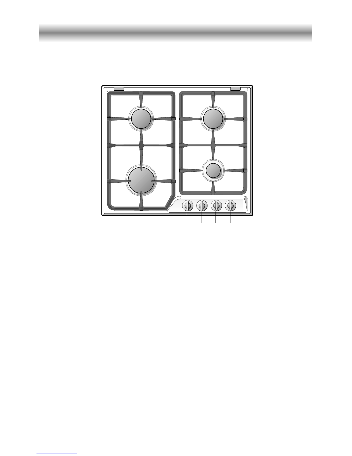
COOKING POINTS
1. Auxiliary burner (A) - 1,00 kW
2. Right medium-speed burner (SR) - 1,75 kW
3. Left medium-speed burner (SR) - 1,75 kW
4. Rapid burner (R) - 3,00 kW
CONTROL PANEL
5. Rapid burner control knob (4)
6. Left medium-speed burner control knob (3)
7. Right medium-speed burner control knob (2)
8. Auxiliary burner control knob (1)
Figure 1
4
How to use your gas hob
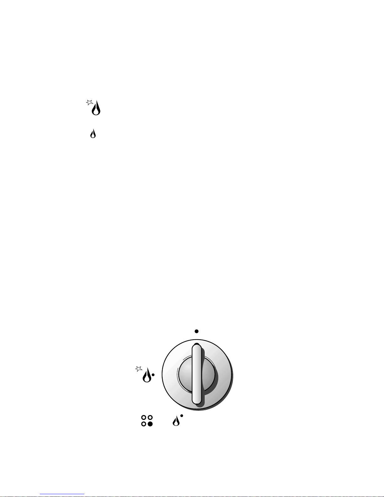
GAS BURNERS
Gas flow to the burners is adjusted by turning the knob illustrated in fig. 2 which controls the safety valves.
Turning the knob so that the indicator line points to the symbols printed on the panel
achieves the following functions:
✓
full circle ● = closed valve
✓
symbol = maximum aperture or flow
✓
symbol = minimum aperture or flow
The maximum aperture position permits rapid boiling of liquids, whereas the minimum
aperture position allows slower warming of food or maintaining boiling conditions of liquids.
To reduce the gas flow to minimum, rotate the knob further anti-clockwise to point
the indicator towards the small flame symbol.
Other intermediate operating adjustments can be achieved by positioning the indicator
between the maximum and minimum aperture positions, not between the maximum
aperture and closed positions.
To switch off, turn the knob clockwise to the off position.
Note: If you are using a burner at the minimum setting, you turn the knob clockwise
past the maximum setting before reaching the off position.
Figure 2
5
6
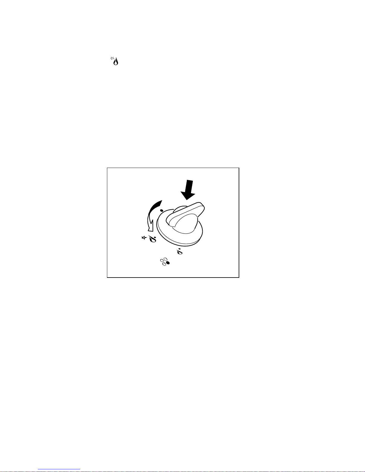
LIGHTING OF BURNERS
To ignite the burners follow these instructions:
– Lightly press the knob (fig. 3) in an anti-clockwise direction up to the maximum
aperture (symbol ); press the knob right down to prime the electric ignition
until the burner lights.
In case of power cut manually light the burner.
– Adjust the burner according to the power required.
If the burner fails to ignite repeat the ignition with the knob on “minimum” position.
Figure 3
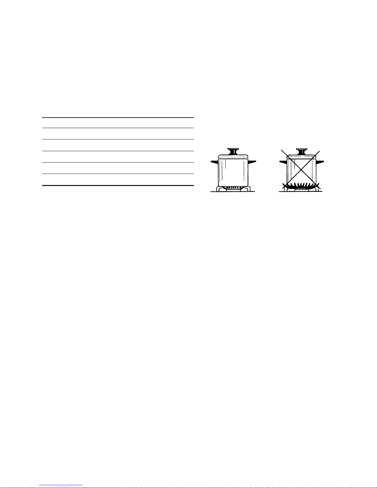
PAN DIAMETER
BURNER MINIMUM MAX.
Auxiliary 6 cm 14 cm
Medium-speed 16 cm 20 cm
Rapid 20 cm 24 cm
do not use pans with concave or convex bases
CHOICE OF BURNER
The burner must be choosen according to the diameter of the pans and energy required.
Attention: During use the hob becomes very hot under the cooking zones.
Keep children away.
Figure 4
Saucepans with handles which are excessively heavy, in relationship to the weight of the
pan, are safer as they are less likely to tip.
Pans which are positioned centrally on burners are more stable than those which are
offset.
It is far safer to position the pan handles in such a way that they cannot be accidentally
knocked.
When deep fat frying fill the pan only one third full of oil.
DO NOT cover the pan with a lid and DO NOT leave the pan unattended.
In the unfortunate event of a fire, leave the pan where it is and turn off all controls.
Place a damp cloth or correct fitting lid over the pan to smother the flames.
DO NOT use water on the fire.
Leave the pan to cool for at least 30 minutes.
7

8
GENERAL TIPS
✓ Before cleaning the hob switch it off and wait for it to cool down.
✓ Clean with a cloth, hot water and soap or liquid detergent.
✓ Do not use products which are abrasive, corrosive or chlorine based.
✓ Do not use steel pads.
✓ Do not leave acid or alkaline substances (vinegar, salt, lemon juice, etc.) on the hob.
ENAMELLED PARTS
✓ All the enamelled parts must be washed only with a sponge with soapy water or
other non-abrasive products.
✓ Dry carefully.
STAINLESS STEEL HOB
✓ Clean with special products which are available on the market.
✓ Dry preferably with chamois leather.
✓ Note: regular use will cause discolouring around the burners, because of the high
flame temperature.
BURNERS AND GRIDS
✓ These pieces can be removed and washed with suitable products.
✓ After cleaning burners and spreaders dry them well and replace them correctly.
✓ In appliances with electric ignition keep the electrode clean so that the sparks
always strike.
✓ Note: To avoid damage to the electric ignition do not use it when the burners
are not in place.
CONTROL KNOBS
✓ The control knobs may be removed for cleaning but care should be taken not to
damage the seal.
GAS TAPS
✓ Regular lubrication of the gas taps must only be performed by qualified engineers.
✓ If the gas taps are not working properly call the After-Sales Service 0870 5425425.
Cleaning and Maintenance

9
CORRECT POSITIONING OF THE BURNERS
It is very important to check that spreader F and cap C of the burner (see Figures 5
and 6) are perfectly in place because if they move out of place serious problems could
arise.
Make sure that electrode "S" (Fig. 5) is kept clean so that the sparks always strike.
Figure 5
Figure 6
S
F
C

10
Important notes
Installation, and any demonstration, information or adjustments are not included in
the warranty and, if requested, the customer must pay the after-sale service
according to the standard fees.
BEFORE CALLING FOR ASSISTANCE
If any burner does not light, check the ignition is working, if not check the 3 amp
fuse, make sure gas is turned on make sure burner caps are in Position correctly.
After Sales Service
Should you require to book a service call telephone 0870 5425425.
For product information and advise telephone 0113 2793520
Attention
The appliance gets very hot, mainly around the cooking areas. It is very
important that children are not left alone in the kitchen when you are
cooking.

11
Do’s and do not’s
DO’S AND DO NOT’S
• Do read the User Instructions carefully before using the hob for the first time.
• Do remove spills as soon as they occur.
• Do not allow children near the hob when in use.
• Do not Clean the hob without first turning off the electricity supply.
• Do not allow vinegar, coffee, milk, saltwater, lemon or tomato juice to remain in
contact with enamel parts.
• Do not use abrasive cleaners or powders that will scratch the stainless steel
surface.
• Do not attemt to repair the internal workings of the hob. Always consult a
suitably qualified person.
• Do not allow water to enter the control panel when cleaning .
FOR YOUR SAFETY
The product should only be used for its intended purpose which is for the
cooking of domestic foodstuffs.
Under no circumstances should any external covers be removed for servicing or
maintenance except by suitably qualified personnel.

12
580
550
100 mm
minimum
500
470
35 mm
minimum
IMPORTANT
✓The hob should only be installed by a C.O.R.G.I. registered installer.
Failure to observe this rule leads to cancellation of the guarantee.
✓The appliance must be installed correctly, in compliance with the regulations in
force and following the manufacturer's instructions.
✓Any repair or maintenance must be performed with the appliance switched off.
✓These appliances have been designed and manufactured to be fitted into heat-
resistant units.
✓These hobs are designed to be fitted into 600 mm deep kitchen units.
✓The unit walls must not be higher than the working surface and must withstand
a temperature of 75°C more than room temperature.
✓Avoid installation near inflammable materials (e.g. curtains).
Figure 7
Installation

13
To fit the hob into the unit make an opening of the dimensions given in Figure 7,
remembering that:
✓Inside the unit there must be a space of at least 30 mm between the bottom of the
hob and the top of a shelf.
✓Any wall to the side and above the hob must be at least 100 mm away (Fig. 7-8).
✓The wall behind the hob must be at least 35 mm away (Fig. 7-8).
✓When there is a wall unit or hood above the hob there must be at least 750 mm
between the hob and the unit or hood (see also Fig. 8).
✓If the hob is not installed over a built-in oven it is essential to install a heat baffle
between the bottom of the hob and the underlying unit
✓If the hob is installed over a built-in oven, there must be a distance of at least 30 mm
between the two appliances. The two appliances should be connected to the gas
supply with independent connections, in compliance with the current laws in force.
750 mm
35 mm min
100 mm min
500 mm
450 mm
Figure 8

14
30 mm
Space for
connections
Depression
space
Door
INSTALLATION ABOVE UNITS WITH DOORS (fig. 9)
The unit must be so constructed that the movement of air caused by closing and opening, even violent, of the doors does not cause the burners to go out.
Leave a depression space of 30 mm between the bottom of the hob and the top of the
unit (Fig. 9).
MOUNTING THE FASTENING TABS (fig. 10)
✓Each hob is supplied with a set of tabs and screws to fasten it to units from 2 to 4 cm
thick.
✓Turn the hob over and put tabs "A" into the mountings; only tighten screws "B" a few
turns. Do not over tighten.
✓Make sure that the tabs are correctly mounted as shown in Figure 10.
FASTENING THE HOB (fig. 10)
✓Stretch gasket "C" above the unit along the edge of the hole made, being careful to
overlay the joining edges.
✓Put the hob into the hole cut into the worktop and position it correctly.
✓Put tabs "A" into place and tighten screws "B" until the hob is completely secured.
✓Carefully trim away the excess gasket material from around the hob.
20 mm min.
40 mm max.
B
C
A
Figure 10Figure 9

15
room volume air vent necessary (effective area)
6 m3to 9 m
3
65 cm
2
6 m3to 9 m
3
35 cm
2
Greater than 11 m
3
no air vent necessary
A room 6 m
3
to 11 m3with a door no air vent necessary
opening to the outside
All rooms require an openable window or equivalent, while some rooms require a permanent vent in addition to a window that can be opened.
This unit must not be used in a room with less than 6 m
3
.
The above requirements allow also for use of a gas oven and grill but if there are other gas
burning appliances in the same room, consult a qualified engineer.
Ventilation

16
Gas Section
IMPORTANT NOTE
This appliance is supplied for use on NATURAL GAS only and cannot be used on any
other gas without modification.
This appliance is manufactured for conversion to LPG. To purchase an LPG conversion
kit telephone accessories direct 0870 6052020.
The gas hob must be installed by a qualified person in accordance with the Gas Safety
(Installation and Use) (Amendment) Regulation 1990 and the relevant Building / I.E.E.
Regulations.
The following British Standards should be used as reference when installing this appliance.
BS6172 1990, BS5440 part 2 1989 and BS6891 1988.
Failure to install the appliance correctly could invalidate any manufacturers warranty
and lead to prosecution under the above quoted regulations.
In the U.K. C.O.R.G.I. registered installers are authorised to undertake the installation
and service work in compliance with the above regulations.

17
Installation to LP Gas
This appliance must only be connected to LPG after an LPG conversion kit has been fitted, (see pages 18-19-20).
When operating on Butane gas a supply pressure of 28-30 mbar is required.
When using Propane gas a supply pressure of 37 mbar is required.
The installation must conform to the relevant British Standards.
Warning: Only a C.O.R.G.I. registered installer, also with technical knowledge of elec-
tricity should install the hob.
He should observe the Regulations and Codes of Practice governing such installation
of gas cookers.
After connecting to the mains, check that the coupling are correctly sealed,
using soapy solution, but never a flame.
GAS CONNECTION
The installation of the hob to Natural Gas or LP Gas must be carried out by a C.O.R.G.I.
registered installer.
Installer shall take due account of the provisions of the relevant British Standards Code
of Practice, the Gas Safety Regulations and the Building Standards (Scotland)
(Consolidation) Regulations issued by the Scottish Development Department.
The cooking hob is supplied with an elbow connection as figure 11 and is adjusted to
work with mains gas.
Installation to Natural Gas
Installation to Natural Gas must
conform to the Code of Practice, etc.
The supply pressure for Natural Gas is
20 mbar.
Figure 11

18
Conversion to LPG
1 -
INJECTORS REPLACEMENT
This appliance is manufactured for conversion to LPG. To purchase an LPG conversion
kit telephone accessories direct 0870 6052020.
To replace the injectors proceed as follows:
– Remove pan-supports and burners from the hobtop.
– By a spanner, remove the injector “J” (fig. 12) from its housing and replace it by the
proper one according to the kind of gas (see following “Table for the choice of the
injectors”).
The burners are conceived in such a way so as not to require the
regulation of the primary air.
J
Figure 12

19
TABLE FOR THE CHOICE OF THE INJECTORS
INCREASE OF AIR NECESSARY FOR GAS COMBUSTION (2 m
3
/h x kW)
BURNERS Air necessary for combustion [m
3
/h]
Auxiliary (A) 2,00
Semi-rapid (SR) 3,50
Rapid (R) 6,00
Cat: II 2H3+
[Hs - kW] [Hs - kW]
Ø injector Ø injector
[1/100 mm] [1/100 mm]
Auxiliary (A) 1,00 0,30 50 72 (X)
Semi-rapid (SR) 1,75 0,45 65 97 (Z)
Rapid (R) 3,00 0,75 85 115 (Y)
G30/G31
28-30/37 mbar
REDUCED
POWER
NOMINAL
POWER
BURNER
G 20
20 mbar
GB

20
Figure 13
2 - MINIMUM BURNER SETTING ADJUSTMENT
Check whether the flame spreads to all burner ports when the burner is lit with the gas
tap set to the minimum position. If some ports do not light, increase the minimum gas
rate setting.
Check whether the burner remains lit even when the gas tap is turned quickly from
the maximum to the minimum position. If the burner does not remain lit, increase the
minimum gas rate setting.
The procedure for adjusting the minimum gas rate setting is described below.
For taps with adjusting screw inside the shaft (fig. 13):
✓ using a screwdriver max. diameter 3 mm turn the screw inside the tap shaft until
the flame setting is correct.
For taps with adjusting screw on the body (fig. 14):
✓ using a screwdriver turn screw "A" until the flame setting is correct.
Normally for Propane gas, fully tighten the adjustment screw.
LUBRICATION OF THE GAS TAPS
If a gas tap is difficult to turn, disassemble it, clean it carefully with petrol and spread
a little high-temperature-resistant grease on it.
These operations must be performed by an Authorized person/Service agent.
Figure 14
A

21
Electrical Connection
For your safety please read the following information
Warning: This appliance must be earthed.
✓
The appliance must be connected to a 220-240 volts 50 cycle AC supply by means of
a three pin socket, suitably earthed and should be protected by a 3 amp fuse in the
plug.
✓
The appliance is supplied with a rewireable 13 amp 3 pin plug fitted with a 3 amp
fuse. Should the fuse require replacement, it must be replaced with a fuse rated at 3
amp and approved to BS1362.
✓
If the mains plug is unsuitable for the socket outlet in your home or is removed for
any other reason, then the cut off plug should be disposed of safely to prevent the
hazard of electric shock.
✓
There is a danger of electric shock if the cut off plug is inserted into any 13 amp socket
outlet.
✓
How to wire a 13 amp plug.
Important
The wires in the mains lead on this appliance are coloured in accordance with the following code:
Green and Yellow - Earth
Blue – Neutral
Brown – Live
✓
As the colours may not correspond with the markings identifying the terminals in
your plug proceed as follows.
✓
The green and yellow wire must be connected to the terminal in the plug which is
marked with the letter E or with the earth symbol or coloured green and yellow.
✓
The blue wire must be connected to the terminal marked N or coloured black.
✓
The brown wire must be connected to the terminal marked L or coloured red.
Figure 15

22
Descriptions and illustrations in this booklet are given as simply indicative. The manufacturer reserves
the right, considering the characteristics of the models described here, at any time and without notice,
to make eventual necessary modifications for their construction or for commercial needs.

23

cod. 1102433 ß3
 Loading...