

Page 1

ESS 903.1
Professional
ceramic cooker
Before operating this cooker,
please read these instructions carefully
Users Operating Instructions
GB
Page 2

2
Dear Customer
Thank you for choosing one of our appliances which has been carefully designed and
built by our specialist staff and thoroughly tested to satisfy your cooking requirement.
We suggest that you read this Instruction Booklet so that you will understand fully how
to operate the appliances.
Please keep the booklet handy. You may wish to refer to it at a later date.
De Longhi
Contents
Page Number
Introduction . . . . . . . . . . . . . . . . . . . . . . . . . . . . . . . . . . . . . . . . . . . . . . . . . . . . . 3
Backguard . . . . . . . . . . . . . . . . . . . . . . . . . . . . . . . . . . . . . . . . . . . . . . . . . . . . . . . 4
Location . . . . . . . . . . . . . . . . . . . . . . . . . . . . . . . . . . . . . . . . . . . . . . . . . . . . . . . . 5
Fitting the adjustable feet - Levelling . . . . . . . . . . . . . . . . . . . . . . . . . . . . . . . . . . 6
Electrical connection . . . . . . . . . . . . . . . . . . . . . . . . . . . . . . . . . . . . . . . . . . . . . . 7
Features and technical data . . . . . . . . . . . . . . . . . . . . . . . . . . . . . . . . . . . . . . . . . 9
Control panel . . . . . . . . . . . . . . . . . . . . . . . . . . . . . . . . . . . . . . . . . . . . . . . . . . . 10
How to use the electronic clock/programmer . . . . . . . . . . . . . . . . . . . . . . . . . . 11
How to use the vitroceramic hob . . . . . . . . . . . . . . . . . . . . . . . . . . . . . . . . . . . 12
How to use the multifunction oven . . . . . . . . . . . . . . . . . . . . . . . . . . . . . . . . . . 17
Temperature recipe guide . . . . . . . . . . . . . . . . . . . . . . . . . . . . . . . . . . . . . . . . . 22
Do’s and do not’s . . . . . . . . . . . . . . . . . . . . . . . . . . . . . . . . . . . . . . . . . . . . . . . . 23
Care and maintenance . . . . . . . . . . . . . . . . . . . . . . . . . . . . . . . . . . . . . . . . . . . . 24
After sales service . . . . . . . . . . . . . . . . . . . . . . . . . . . . . . . . . . . . . . . . . . . . . . . . 29
Page 3

3
Introduction
Congratulations on your purchase of this De Longhi ceramic cooker which has been
carefully designed and produced to give you many years of satisfactory use.
Before using this appliance it is essential that the following instructions are carefully read and
fully understood.
We would emphasise that the installation section must be fully complied with for your safety
to ensure that you obtain the maximum benefits from your appliance.
This cooker has been designed, constructed and marketed in compliance with:
- safety requirements of EEC Directive “Low voltage” 73/23;
- protection requirements of EEC Directive “EMC” 89/336;
- requirements of EEC Directive 93/68.
This appliance is designed and manufactured solely for the cooking of domestic
(household) food and in not suitable for any none domestic application and therefore
should not be used in a commercial environmement.
The appliance guarantee will be void if the appliance is used within a none domestic
environnement i.e. a semi commercial, commercial or communal environment.
Page 4
V
A
B
4
Backguard
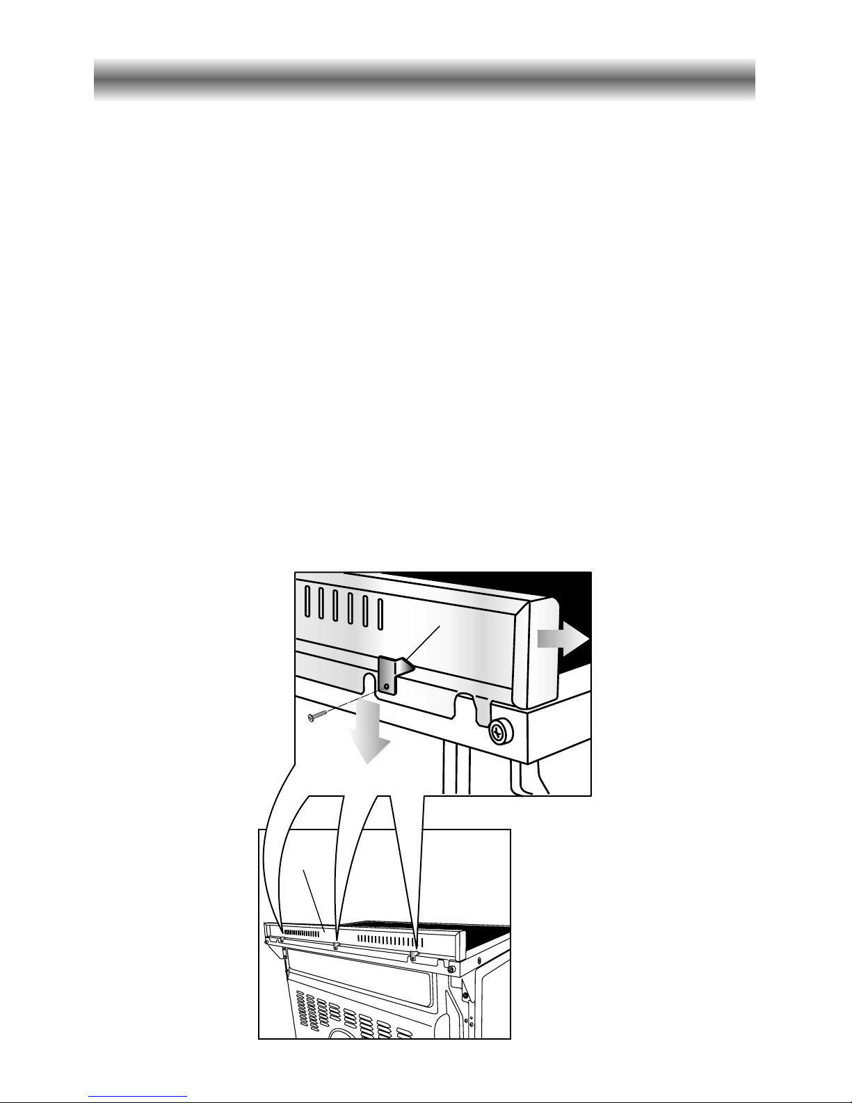
Before installing the cooker, assemble the backguard “V” (fig. 1).
Please note that :
• The backguard “V” can be found packed at the rear of the cooker.
• Before assembling remove any protective film/adhesive tape.
• The backguard must be fixed to the cooktop using the three supports “B” supplied with
the appliance (see fig. 1).
Fig. 1
Backguard
Page 5
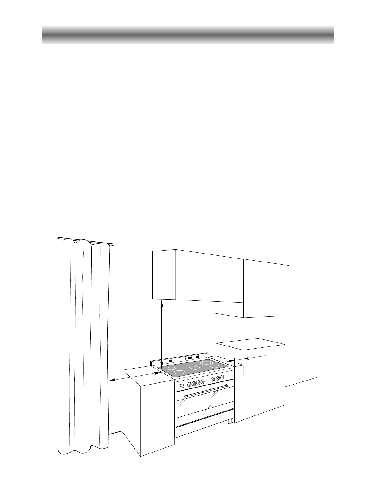
50 mm
500 mm
750 mm
The cooker has type “Y” overheating protection.
The cooker must be installed no less than 50 mm away from any side wall which exceed
the height of the cooktop;
The appliance must be housed in heat resistant units.
The walls of the units must be capable of resisting temperatures of 75 °C above
room temperature.
Do not install the appliance near inflammable materials (eg. curtains).
Location
Important
– The appliance should be installed by a qualified electrician in compliance with the laws
in force in your country and in observation of the instructions supplied by the
manufacturer.
Failure to comply with this condition will render the guarantee invalid.
– Always disconnect the cooker from mains power supply before carrying out any
maintenance operations or repairs.
5
Fig. 2
Page 6
6
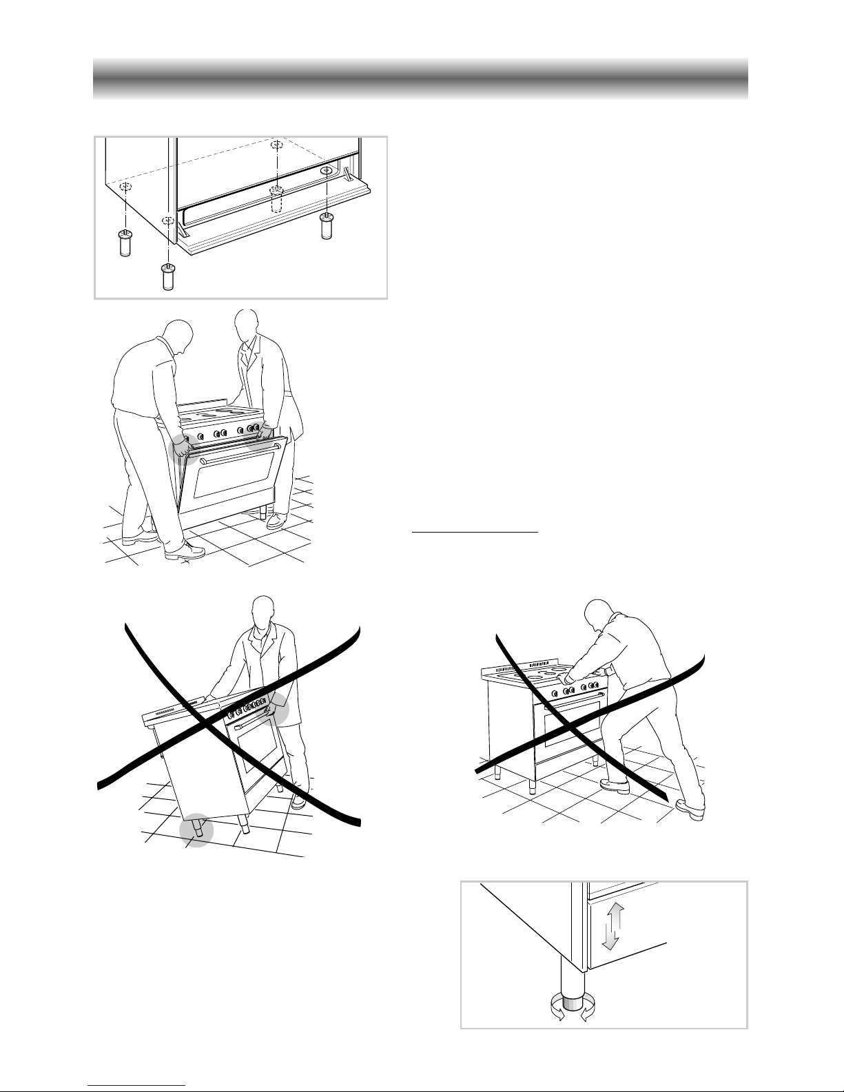
Fitting the adjustable feet
Fig. 4
Fig. 5
Fig. 6
The adjustable feet must be fitted to the
base of the cooker before use.
Rest the rear of the cooker on a piece of
the polystyrene packaging exposing the
base for the fitting of the feet.
WARNING
When raising cooker to upright position
always ensure two people carry out this
manoeuvre to prevent damage to the
adjustable feet (fig. 4).
WARNING
Be carefull: do not lift the cooker by
the door handle when raising to the
upright position (fig. 5).
WARNING
When moving cooker to its final position
DO
NOT DRAG (fig. 6).
Lift feet clear of floor (fig. 4).
Fig. 3
Levelling the cooker
The cooker may be levelled by screwing the lower ends of the feet IN or
OUT (fig. 7).
Fig. 7
Page 7

Electrical connection
Voltage
230 Volts AC - 50 Hz
Maximum rated current : 11370 W
Warning! This appliance must be earthed
Before working on the electrical parts the appliance must be disconnected
from the mains.
Power connection
This appliance must be installed by a qualified electrician in accordance with the current
local regulations and in compliance with the manufacturer instructions.
The appliance must be connected directly to the mains placing an omnipolar switch
with minimum opening between the contacts of 3 mm between the appliance and the
mains.
All electrical wiring must be in compliance with the appropriate IEE regulations and carried
out by a qualified electrician.
Before installing the cooker the electricity must be turned off.
The electrical connections must be connected to the terminal block as detailed opposite.
A cable of the correct rating of this appliance must be used type H05 RR-F section 6 mm
2
.
Cable must be able to withstand a temperature rise of 75°C above ambient temperature.
7
Page 8
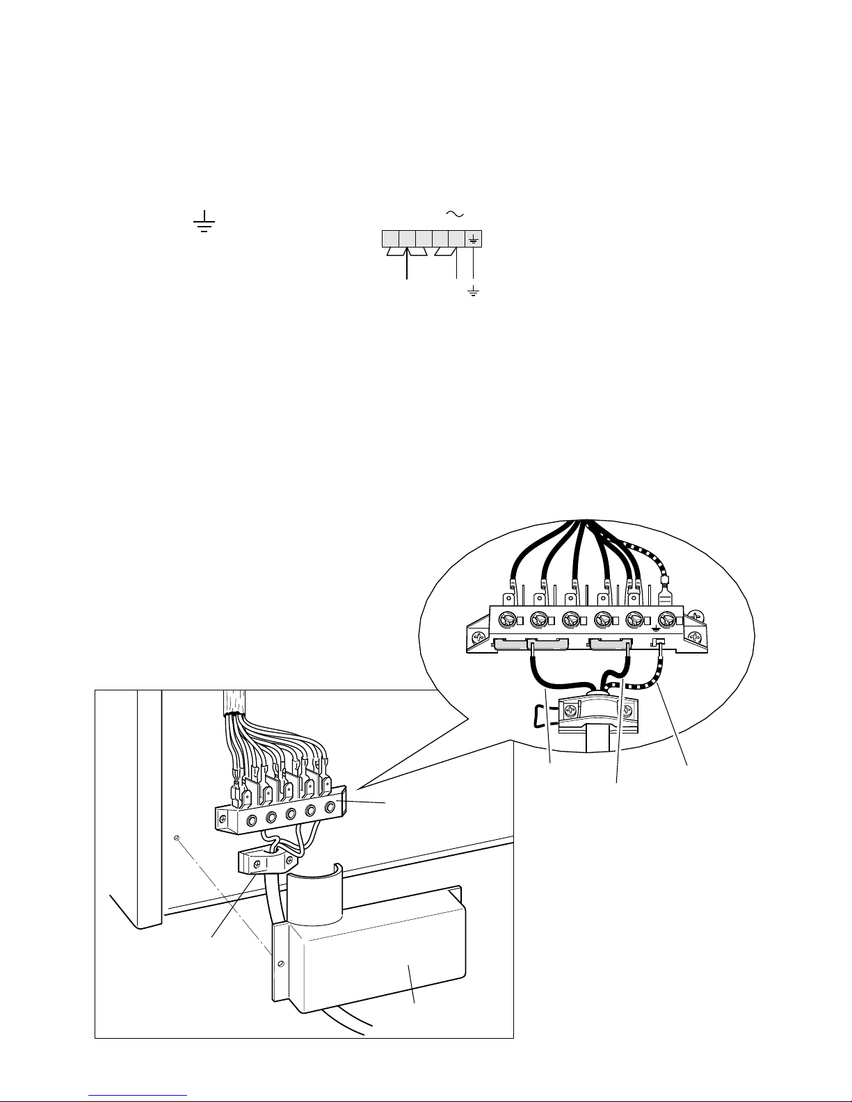
Connecting the mains cable
– Remove the two screws securing the cover plate A behind the cooker.
– Open completely the cable clamp D.
– Insert the mains cable (type HO5 RR-F) of section minimum 6 mm
2
into the cable clamp D.
– Connect the live, neutral and earth cables to the mains terminal connection block B.
EARTH
N NEUTRAL
L LIVE
– Refit the cable clamp D so that it clamps the outer sleeving of the cable.
– Refit the cover plate A.
Green &Yellow
(Earth)
Red
or
Brown
(Live)
Black
or
Blue
(Neutral)
A
D
B
23451
N(L2)
PE
L1
12345
N(
L
2)L1
PE
230 V
Fig. 10
Fig. 9
8
Page 9

Features and technical data
Fig. 11
2
1
3
5
4
Identification label
When you open the oven
door the indentification label
is at the bottom right hand
side.
Vitroceramic cooking hob
1. 3 circuits cooking zone Ø 180 1700 W
2. 3 circuits cooking zone Ø 145 1200 W
3. Oval cooking zone Ø 145 x 250 1800/1000 W
4. Double cooking zone Ø 210/120 2100/700 W
5. 3 circuits cooking zone Ø 145 1200 W
6. Cooking zone residual heat indicators
Multifunction oven
– Bottom element 1725 W
– Top element 1725 W
– Grill element 2500 W
– Circular element 2500 W
– Fan motor 25 W
– Oven lamp 15 W
– Usable oven volume 100 dm
3
6
9
Page 10
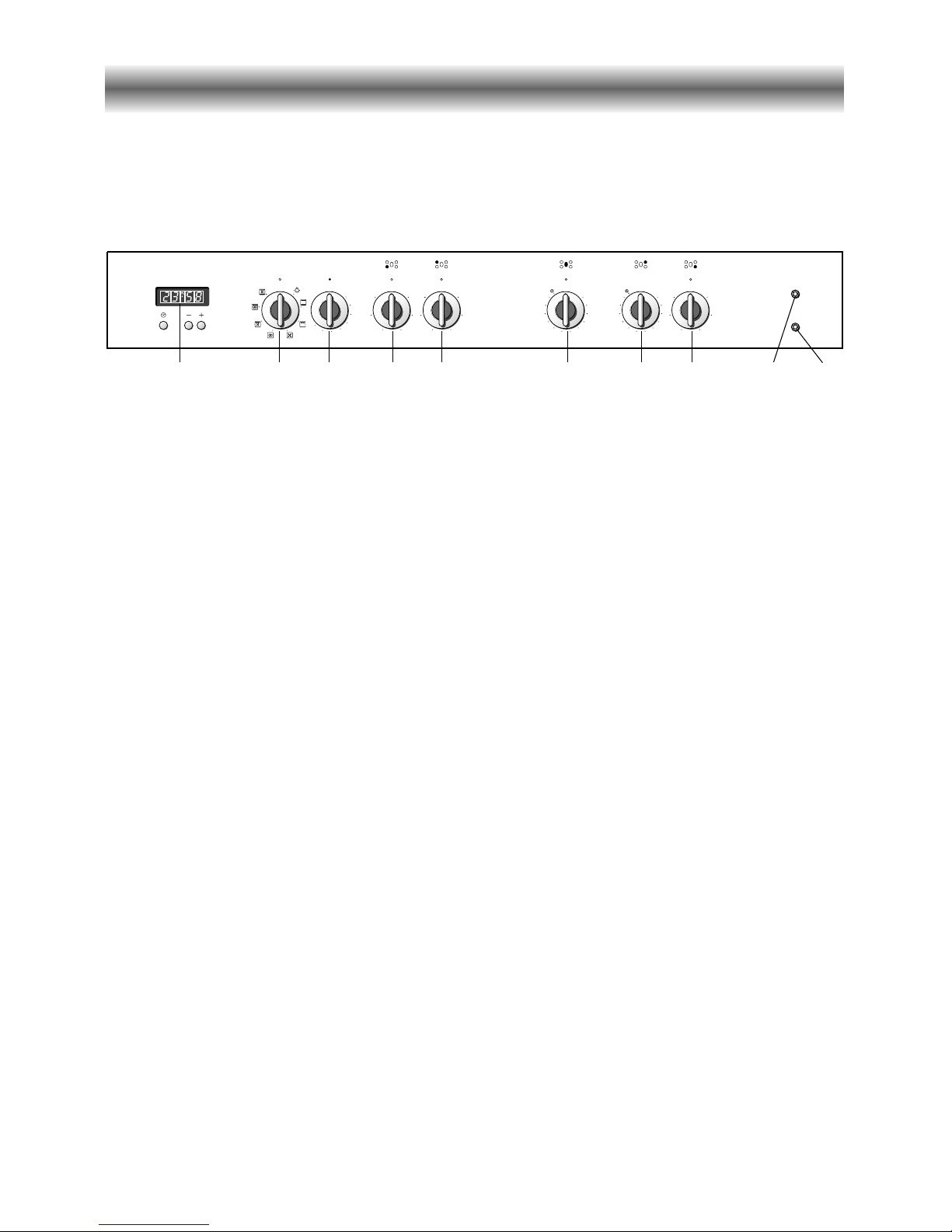
Control panel
Fig. 12
Professional
ESS 903.1
Function
Temperature
225
175
125
50
75
6
5
4
3
2
1
12
11
10
9
8
7
6
5
4
3
2
1
12
11
10
9
8
7
6
5
4
3
2
1
6
5
4
3
2
1
6
5
4
3
2
1
A
U
T
O
12345 678
CONTROL PANEL - Controls description
1. Electronic clock/programmer
2. Multifunction oven switch knob
3. Multifunction oven thermostat knob
4. Front left cooking zone knob
5. Rear left cooking zone knob
6. Central cooking zone knob
7. Rear right cooking zone knob
8. Front right cooking zone knob
9. Cooking hob ON indicator light
10. Oven thermostat indicator light
109
10
Page 11

How to use the electronic clock/programmer
A
U
T
O
Fig. 13
The electronic programmer is a device
with the following functions:
– 24 hours clock with illuminated display
– Timing of oven cooking with automatic
switch-off (max. 99 minutes).
Electronic clock
Upon immediate connection of the oven
or after a mains failure, three zeros will
flash on the programmer panel.
To set the clock it is necessary to push the
button and then, within 7 seconds, the
or button until you have set the
correct time.
The clock will show zero after a mains
failure.
Attention: When the programmer display
shows three flashing zeros the oven
cannot be switched on.
The oven can be switched on when the
symbol is shown in the display.
Cooking with automatic
switch-off
The aim of this function is to automatically
stop the cooking after a pre programmed
time, for a maximum period of 99 minutes.
To set the cooking time, push the or
button until you obtain the desired
time in the display. The symbol AUTO
will be shown in the display. Then you
adjust the oven thermostat knob
according to the required temperature.
The oven will immediately start to operate
and will work for the pre programmed
time. The display shows the count down.
Clock time can be displayed by pressing
the button. Once the time has
elasped, the oven will switch off
automatically, the symbol AUTO will go
off and an intermittent buzzer, lasting 7
minutes, will start; this can be stopped by
pressing the button.
Important: Before the buzzer is
stopped switch off the oven manually.
To cancel the cooking program at any time
press the and buttons together and
release the button first.
Setting the frequency of
the alarm sound
The selection from 3 possibilities of
sound can be made by pressing the
button.
Electronic alarm
The programmer can be used as an alarm
only for a maximum period of 99 minutes.
To set the alarm, push the or
button until you obtain the desired time in
the display. Once the time has elasped,
an intermittent buzzer, lasting 7 minutes,
will start; this can be stopped by pressing
the button.
Attention: If the bottom oven is
switched on when the buzzer starts, it
will be automatically switched off. For
it to operate furtherly you have to stop
the buzzer by pressing the button.
11
Page 12

How to use the vitroceramic hob
The ceramic surface of the hob allows a
fast transmission of heat in the vertical
direction, from the heating elements
underneath the ceramic glass to the pans
sat on it.
The heat does not spread in the horizontal
direction, so that the glass stays “cool” at
only a few centimeters from the cooking
plate.
The 5 cooking plates are shown by dark
disks on the ceramic surface.
6
5
4
3
2
1
3 circuits hotplate
Incorporating 3 heating elements you can
control and light up all together or separately by a 6 position switch.
Reaches the working temperature in a very
short time.
Fig. 14
12
Page 13

12
11
10
9
8
7
6
5
4
3
2
1
Fig. 15
Fig. 17
Fig. 16
Second element
Second element
Double and oval radiant
zones
The heating element is formed of a coil of
resistant material which reaches the working temperature quickly.
Operation of the cooking zone is controlled by a continuous energy regulator
from “1” to “12” (maximum temperature)
(fig. 15).
By switching on the second element (fig.
16 and 17), the surface area of the rear
right and central radiant zones can be
extended.
For this purpose, turn the control knob
(fig.
15)fully to the right (position
).
13
Page 14

1
2
3
4
5
6
After a short period of use, experience
will teach you which setting is the right
one for your needs.
Cooking hints
Heating
Cooking
Roasting-frying
Fig. 18
1
2
3
4
5
6
7
8
9
10
11
12
Cooking plate
controlled by a
7 position
switch
Cooking plate
controlled by a
12 position
switch
Type of cooking
Switched OFF
For melting operations
(butter, chocolate).
To maintain food hot and to
heat small quantities of liquid
(sauces, eggs).
To heat bigger quantities; to
whip creams and sauces.
(vegetables, fruits, soups).
Slow boiling, i.e.: boiled
meats, spaghetti, soups,
continuations of steam cooking
of roasts, stews, potatoes.
For every kind of frying, cutlets,
uncovered cooking, i.e.:
risotto.
Browning of meats, roasted
potatoes, fried fish, omelettes,
and for boiling large quantities
of water.
Fast frying, grilled steaks, etc.
Switching on the second
element (Double and oval
radiant plate only)
0
Knob
setting
1
2
3
4
5
6
2
0
1
2
2
3
4
3
4
6
7
4
7
8
4
5
8
9
10
6
11
12
14
Page 15

Cooking hints
– To reduce the cooking time, you can turn the control knob to the max when you switch
the plate on.
After a short time you set the control knob to the required position for the cooking.
– You should use pots and pans with flat bases.
The diameter of the pan should match that of the cooking plate (or be slightly bigger) to
make the most of the energy.
– Since the cooking surface stays hot for a certain time after the plate has been switched off,
you can switch it off minutes before the end of the cooking.
The residual heat of the hob will terminate the cooking.
– To save electricity, use lids whenever possible.
Fig. 19
15
Page 16

Cleaning the hob
Before you begin cleaning make sure
that the appliance is switched off.
Remove spillages and other types of
incrustations by using a scraper.
Dust or food particles can be removed
with a damp cloth.
If you use a detergent, please make sure
that it is not abrasive or scouring. Abrasive
or scouring powders can damage the
glass surface of the hob.
All traces of the cleaner have to be
removed with a damp cloth.
It is highly recommended to keep off the
hob any article which can melt: plastic,
aluminium foil, sugar, sugar syrup mixtures
etc.
If any of these products has melted on the
ceramic surface, you should remove it
immediately (while the surface is still hot)
by using a scraper to avoid any
permanent damage to the surface of the
hob.
Avoid using any knife or sharp utensil
since these can damage the ceramic.
Do not use steel wool or an abrasive
sponge which could scratch the surface
in an irrepairable way.
ATTENTION: MOST IMPORTANT!
If cleaning the glass ceramic hob using
a special tool (i.e. scraper) take extra
care to avoid damage to the seal at the
edges of the glass ceramic surface.
Safety hints:
– Before you switch the hob on, make sure
you know which knob controls the
required cooking plate. We advise you to
sit the pan over the cooking plate before
switching it on. Remove the pan after you
have switched the cooking plate off.
– Do not use pots and pans with rough
bases (pay attention to cookware made
of cast-iron). Rough bases can damage
the glass surface of the hob (scratches).
Make sure that the pan bottom is dry and
clean.
– Pots with aluminium bottoms may leave
silver streaks or spots on the hob.
– Pan handles should never stand out
beyond the kitchen worktop, as there is a
great danger of knocking the pan over.
This will also ensure that children cannot
reach them.
– Do not use the cooker if the glass surface
is broken or cracked in any way. Please
disconnect the appliance from the mains
and call the After-Sales Service.
– Do not lean over the cooking plate when
in use.
– Do not lay cooking foil, aluminium foil or
plastic materials on the ceramic surface
when it is hot.
– Remember that the surface remains hot for
a long time (about 30 min.) after the
cooking plate has been switched off.
Keep children well out of reach
– Do not use the glass surface for storage.
– Follow the cleaning instructions carefully.
Fig. 20
16
Page 17

How to use the Multifunction oven
OPERATING PRINCIPLES
Heating and cooking in the MULTI-FUNCTION oven are obtained in the following
ways:
a. by normal convection
The heat is produced by the upper and lower heating elements.
b. by forced convection
A fan sucks in the air contained in the oven muffle, which sends it through the
circular heating element and then sends it back through the muffle. Before the
hot air is sucked back again by the fan to repeat the described cycle, it envelops
the food in the oven, provoking a complete and rapid cooking.
It is possible to cook several dishes simultaneously.
c. by semi-forced convection
The heat produced by the upper and lower heating elements is distributed
throughout the oven by the fan.
d. by radiation
The heat is radiated by the infra red grill element.
e. by radiation and ventilation
The irradiated heat from the infra red grill element is distributed throughout the
oven by the fan.
Please note: This appliance incorporates a safety cooling fan which you will hear
operating whenever the oven or grill are in use. This fan is to reduce the external
temperature of the appliance and cool the internal components.
17
Page 18

Function
Temperature
225
175
125
50
75
FUNCTION SELECTOR KNOB (Fig. 21)
Rotate the knob clockwise to set the oven
for one of the following functions.
THERMOSTAT KNOB (Fig. 22)
This only sets the cooking
temperature and does not switch
the oven on. Rotate clockwise until
the required temperature is reached
(from 50 to 225°C).
Fig. 21
Fig. 22
OVEN LIGHT
By setting the knob to this position, only the oven light comes on (15 W).
It remains on in all the cooking modes.
TRADITIONAL CONVECTION COOKING
The upper and lower heating elements come on. The heat is dispersed by natural
convection and the temperature must be set to between 50° and 225°C via the
thermostat knob.
The oven must be preheated before cooking.
Recommended for:
Food that requires the same degree of cooking both inside and out, for example
roasts, spare pork ribs, meringues etc.
18
Page 19

HOT AIR COOKING
The circular element and fan come on. The heat is dispersed by forced convection
and the temperature can be regulated to between 50° and 225°C via the
thermostat knob. The oven does not require preheating.
Recommended for:
Food which has to be well-cooked outside and soft or rosy inside, for example
lasagne, lamb, roast beef, whole fish etc.
DEFROSTING FROZEN FOODS
Only the oven fan comes on. Use with the thermostat knob set to “●” - other positions
have no effect. The food is thawed by ventilation without heating.
Recommended for:
Quick thawing of frozen foods; one kg requires approximately 1 hour.
Thawing times vary according to the quantity and type of food to be thawed.
GRILLING
The infrared grill element comes on. The heat is dispersed by radiation.
Set the thermostat knob to between 50° and 200°C.
Always grill with the oven door closed.
For cooking hints, see the chapter “USE OF THE GRILL”.
Recommended for:
Intense grilling, browning, cooking au gratin and toasting etc.
Do not grill for longer than 30 minutes at any one time on full heat (200°C).
Caution: the oven door becomes very hot during operation.
Keep children well out of reach.
19
Page 20

VENTILATED GRILL COOKING
The infrared grill element and the fan come on. The heat is dispersed mainly by
radiation and the fan then distributes it all over the oven.
Use with the door closed. The temperature can be regulated via the
thermostat knob to between 50° and 175° max.
The oven must be preheated for approximately 5 minutes. For cooking hints, see
the chapter “GRILLING AND COOKING AU GRATIN.
Recommended for:
Grilling where quick browning on the outside is required to keep the juices in.
For example: veal steaks, chops, hamburgers etc.
Do not grill for longer than 30 minutes at any one time on full heat (175°C).
Caution: the oven door becomes very hot during operation.
Keep children well out of reach.
MAINTAINING TEMPERATURE AFTER COOKING OR
SLOWLY HEATING FOODS
The upper heating element, the circular element and the fan come on.
The heat is dispersed by forced convection with greater intensity in the upper part.
The temperature can be set to between 50° and 140°C via the thermostat knob.
Recommended for:
Keeping food warm after any type of cooking. Slow heating of cooked food.
CONVECTION COOKING WITH VENTILATION
The upper and lower heating elements come on and the fan.
The heat coming from above and below is dispersed by convection with ventilation.
The temperature can be set to between 50° and 225°C via the thermostat knob.
Recommended for:
Voluminous dishes and large quantities which require the same degree of cooking
both inside and out, for example rolled roasts, turkey, roast legs, cakes etc.
20
Page 21

COOKING ADVICE
STERILIZATION
Sterilization of foods to be conserved, in full and hermetically sealed jars, is done in the
following way:
a. Set the switch to position .
b. Set the thermostat knob to position 185 °C and preheat the oven.
c. Fill the dripping pan with hot water.
d. Set the jars onto the dripping pan making sure they do not touch each other and
the door and set the thermostat knob to position 135 °C.
When sterilization has begun, that is, when the contents of the jars start to bubble,
turn off the oven and let cool.
REGENERATION
Set the switch to position and the thermostat knob to position 150° C.
Bread becomes fragrant again if wet with a few drops of water and put into the oven
for about 10 minutes at the highest temperature.
SIMULTANEOUS COOKING OF DIFFERENT FOODS
The MULTI-FUNCTION oven set on position consents a simultaneous
heterogeneous cooking of different foods. Different foods such as fish, cake and
meat can be cooked together without mixing the smells and flavors together. This
is possible since the fats and vapors are oxidized while passing through the
electrical element and therefore are not deposited onto the foods.
The only precaution to follow are:
– The cooking temperatures of the different foods must be as close to as possible,
with a maximum difference of 20° - 25 °C.
– The introduction of the different dishes in the oven must be done at different
times in relation to the cooking times of each one.
The time and energy saved with this type of cooking is obvious.
21
Page 22

USE OF THE GRILL
Preheat the oven for about 5 minutes.
Introduce the food to be cooked, positioning the rack as close to the grill as
possible.
The dripping pan should be placed under the rack to catch the cooking juices
and fats.
Grilling with the oven door closed.
Do not grill for longer than 30 minutes at any one time on full heat (200°C).
Caution: the oven door becomes very hot during operation.
Keep children well out of reach.
ROASTING
To obtain classical roasting, it is necessary to remember:
– that it is advisable to maintain a temperature between 180° and 200 °C.
– that the cooking time depends on the quantity and the type of foods.
GRILLING AND “AU GRATIN”
Grilling may be done without the roasting jack on position of the switch,
because the hot air completely envelops the food that is to be cooked.
Set the thermostat to position 175 °C and after having preheated the oven, simply
place the food on the rack.
Close the door and let the oven operate with the thermostat on position 175 °C,
until grilling is done.
Adding a few dabs of butter before the end of the cooking time gives the golden
“au gratin” effect.
Do not grill for longer than 30 minutes at any one time on full heat (175°C).
Caution: the oven door becomes very hot during operation.
Keep children well out of reach.
22
Page 23

APPROX. HEAT OF TYPE OF DISH TO COOK
TEMPERATURE OVEN
125°C Very cool Meringue,
(257°F) oven slow cooking foods.
135°C - 140°C Cool or Milk puddings, very rich fruit
(275°F - 285°F) slow oven cakes, eg., Christmas.
150°C Cool or Stews, casseroles, braising,
(300°F) slow oven rich fruit cakes, eg., Dundee.
160°C - 170°C Warm oven Biscuits, Low temperature roasting,
(320°F - 338°F) rich plain cakes eg., Madeira cake.
180°C Moderate Plain cakes, eg., Victoria
(356°F) oven sandwich, meat pies.
190°C Fairly hot Small cakes, savoury flans,
(374°F) oven fish.
200°C Hot oven Plain cakes and buns, swiss rolls,
(392°F) fruit pies. High temp. roasting.
215°C Moderately Bread and bread rolls etc., scones,
(419°F) hot oven flaky and rough puff pastry,
Yorkshire pudding.
225°C Very hot Sausage rolls, mince pies, puff
(437°F) oven pastry.
Browning ready cooked dishes.
Temperature recipe guide
23
Page 24

Do’s and do not’s
General
• Do read the User Instructions carefully before using the cooker for the first time.
• Do not allow children near the cooker when in use.
• Do not clean the hob or oven without first turning off the electricity supply.
• Do not use abrasive cleaners or powders that will scratch the stainless steel surface.
• Do not attempt to repair the internal workings of the cooker. Always consult a qualified
technician.
Hob
• Do ensure that pan handles are turned to a safe position.
• Do use pans with lids.
• Do clean the hob regularly.
• Do remove spills as soon as they occur.
• Do not use small pans on large plates.
• Do not overfill pans.
Oven
• Do allow the oven to heat for one and a half hours, before using for the first time, in order
to expel any smell from the new oven insulation, without the introduction of food.
• Do clean your oven regularly.
• Do not allow vinegar, coffee, milk, saltwater, lemon or tomato juice to remain in contact
with enamel parts.
• Do remove spills as soon as they occur.
• Do always use oven gloves when removing food shelves and trays from the oven.
• Do not allow fat or oils to build up in the oven trays, grill pan or oven base.
• Do not place cooking utensils or plates directly onto the oven base.
• Do not grill food containing fat without using the grid.
• Do not cover the grilling grid with aluminium-foil.
• Do not use the oven tray for roasting.
• Do not place hot enamel parts in water. Leave them to cool first.
For your safety
The product should only be used for its intended purpose which is for the cooking of
domestic foodstuffs.
Under no circumstances should any external covers be removed for servicing or
maintenance except by suitably qualified personnel.
24
Page 25

Care and maintenance
The hob
Spillage on the hob can usually be removed by a damp soapy cloth. More obstinate stains
can be removed by rubbing gently with a soapy scouring pad or mild household cleaner.
Avoid scratching or scraping the surface.
Spillage
Any spillage should be dealt with as soon as possible to prevent it becoming burnt on.
The oven
The oven interior and the chromium plated shelves can be cleaned with a damp soapy
cloth. Obstinate stains can be removed with scouring pads and a gentle, non abrasive,
liquid cleaner. Provided the oven is wiped over immediately after roasting, only the
minimum of cleaning should be necessary.
Enamelled parts
All of the enamelled parts must be washed only with a sponge and soapy water or with
non-abrasive products and then dried with a clean cloth.
Stainless steel surfaces
The stainless steel front panels on this cooker (facia, oven door, drawer or storage
compartment) are protected by a finger-print proof lacquer. To avoid damaging this lacquer,
do not clean the stainless steel with abrasive cleaners or abrasive cloths or scouring pads.
ONLY SOAP/WARM WATER MUST BE USED TO CLEAN THE STAINLESS STEEL SURFACES.
Grill heating element
The heating element is self-cleaning and does not require maintenance.
Always switch the cooker off at the mains isolating switch before cleaning.
NOTE:
Any cleaners such as spray or stick cleaners which are used on enamel must have the VEDC
(Vitreous Enamel Development Council) seal of approval and the manufacturers instructions
must be followed.
25
Page 26

Storage compartment
– The storage compartment is accessible through the pivoting panel.
Do not store flammable material in the oven or in the storage
compartment.
Fig. 23
Fig. 24
Removal of the inner glass door panel
– The inner glass door panel can easily be removed for cleaning by unscrewing
the four screws (fig. 23).
– When re-assembly ensure that the inner glass is correctly positioned and do not
over tighten the screws.
26
Page 27

Oven tray
The oven tray must be correctly
placed on the wire shelf (fig. 27) then
inserted into the side runners (fig. 28).
Oven floor
The oven floor “F” (fig. 28) can be easily removed to facilitate cleaning.
Remember to replace the floor correctly afterwards.
Be careful not to confuse the tray
“L” with the oven floor “F”.
Fig. 28
Fig. 27
Assembling and removing the side racks
Hang up the wires racks on the oven walls (fig. 25)
Slide the required grid or tray into the guides (fig. 26).
Fig. 25 Fig. 26
L
F
27
Page 28

Door assembly
● Grip the door (as indicated in
figure 29) and refit it in reverse
order of removing procedure.
Removing the oven door
Please operate as follows:
● Open the door completely.
● The swivel retainers of the rh and
lh hinges (fig. 29a) are hooked
onto the metal bar above them
(fig. 29b).
● Lift the oven door slightly. The
noch on the bottom of the hinge
will disengage (fig. 29c).
● Now pull the oven door forwards
off the appliance. Release both
hinge sections from the slots (fig.
29d).
Fig. 29
Fig. 29a
Fig. 29b
Fig. 29c
Fig. 29d
28
Page 29

After Sales Service
If you should require After Sales Service please contact your nearest COMET Service Centre.
For technical information telephone the Comet Customer Help Line 0113 2793520.
Oven light not working
If the oven lights fail, you can easily change the bulb.
1. Disconnect the electrical power supply (for example, by switching off the main
power switch).
2. Unscrew the light cover
3. Fit a new bulb.
4. Refit the cover.
Note:
Use only bulbs designed to resist up to 300°C with the following characteristics: 15 W,
230 V, type E-14.
Spare bulbs can be ordered from Accessories direct telephone 0870 6052020.
Other indicator lights cannot be changed by yourself and should be replaced by a
qualified technician.
IMPORTANT! WARNING - COOKER GETS HOT. YOU MUST WARN CHILDREN OF THIS
DANGER.
If your oven is not working
Check the following points:
1. Is there power to the cooker.
2. Check that the electronic programmer is set to manual.
3. If your appliance is still not working contact your nearest COMET Service Centre.
After Sales Service
29
Page 30

30
Page 31

Descriptions and illustrations in this booklet are given as simply indicative. The manufacturer reserves the right,
considering the characteristics of the models described here, at any time and without notice, to make eventual
necessary modifications for their construction or for commercial needs.
31
Page 32

Cod. 1102208
ESS 903.1 cooker
 Loading...