

Page 1
Page 1 of 7Spares - FP250 Disassembly & re-assembly instructions
FP250
The following procedures are aimed to help with dismantling and service repairs.
Always disconnect the appliance from mains supply prior to removal of the covers and suitably protect the finish on the
casings.
Click on the pictures to open a larger version in a seperate wind ow.
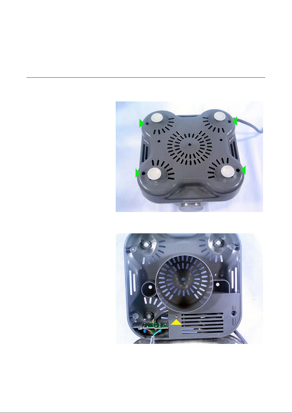
Remove the base which is secured by
four screws.
Remove the screw securing the stuffer
box cover.
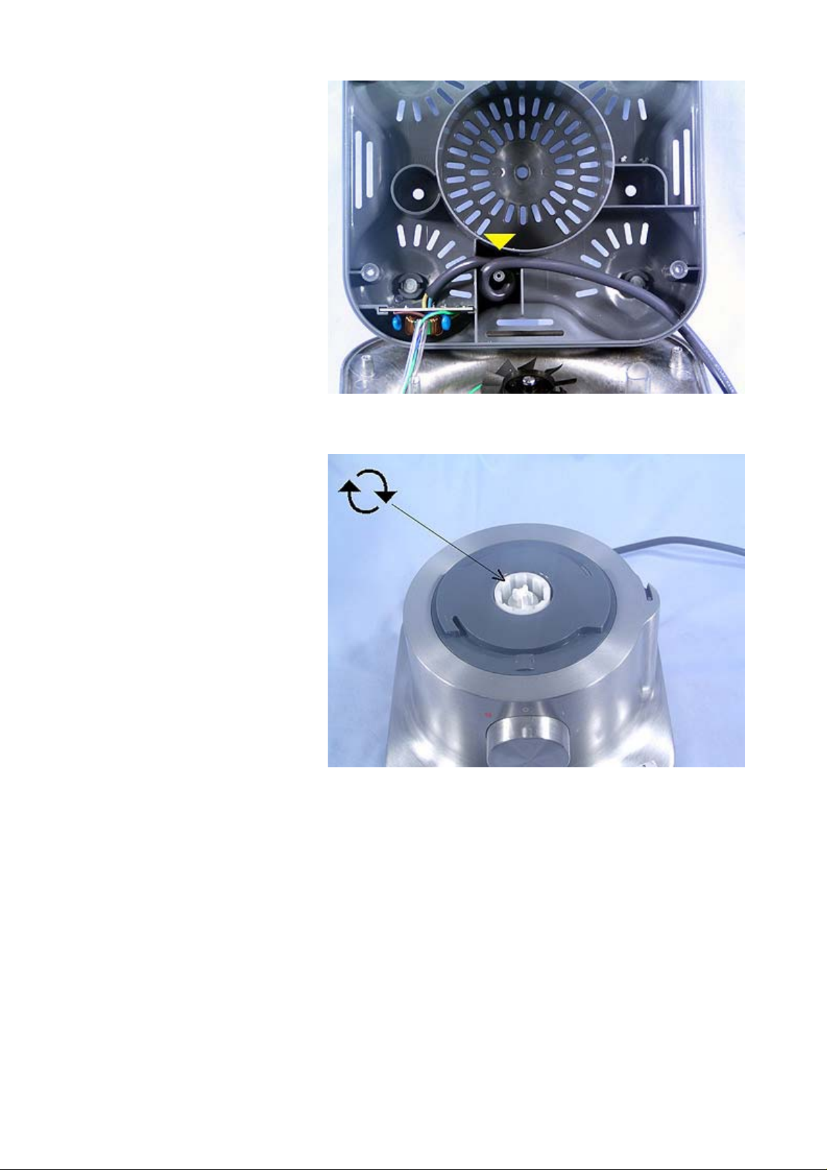
Please note the correct route for the
supply cord.
30/04/2009http://www.kenwoodservice.co.uk/product-files-kar/guide_FP250.htm
Page 2
Page 2 of 7Spares - FP250 Disassembly & re-assembly instructions
To remove the drive coupling, steady
the motor by placing a screwdriver in
the slot at the bottom of the a rmature
shaft, and using pliers turn the drive
coupling in a clockwise direction.
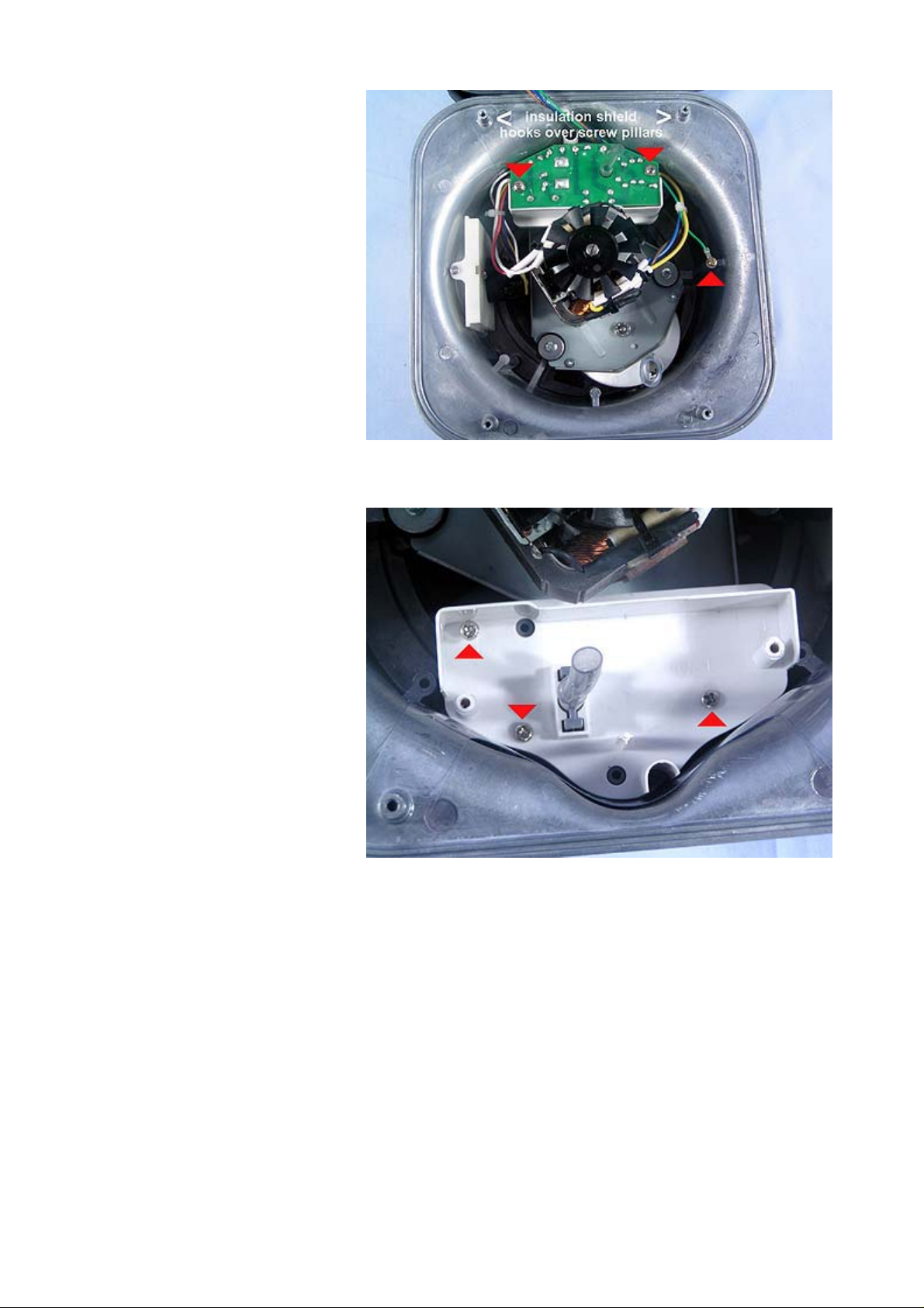
Remove both PCB screws and the
earth screw. Ensure the insulation
shield is fitted.
30/04/2009http://www.kenwoodservice.co.uk/product-files-kar/guide_FP250.htm
Page 3
Page 3 of 7Spares - FP250 Disassembly & re-assembly instructions
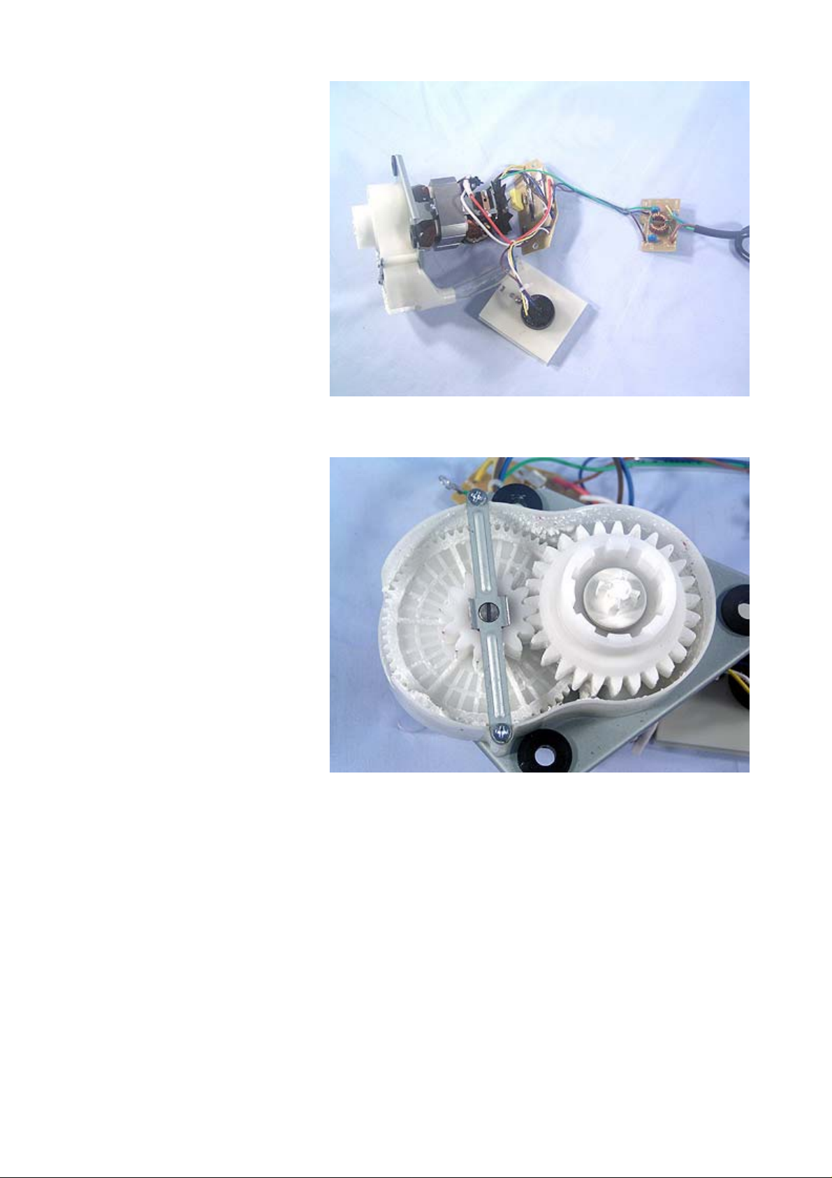
Remove the three screws indicated
and lift out the interlock assembly.
The drainage tube is glued onto the
interlock moulding, therefore this
complete assembly will be supplied as
sub-assembled parts.
30/04/2009http://www.kenwoodservice.co.uk/product-files-kar/guide_FP250.htm
Page 4

Page 4 of 7Spares - FP250 Disassembly & re-assembly instructions
Remove the three motor retaining
screws and switch carrier screw, then
lift the motor, PCB, and switch
assembly out of the body.
The motor, PCB, switch, noise filter
and supply cord.
30/04/2009http://www.kenwoodservice.co.uk/product-files-kar/guide_FP250.htm
Page 5
Page 5 of 7Spares - FP250 Disassembly & re-assembly instructions
The gearbox assembly.
Please note correct position for the
insulation tabs. These must be glued
in position. The bayonet cover is
secured by the two screws and one
locating lug, as shown.
30/04/2009http://www.kenwoodservice.co.uk/product-files-kar/guide_FP250.htm
Page 6

Page 6 of 7Spares - FP250 Disassembly & re-assembly instructions
The control knob is secured internally
as shown here. Remove the three
screws from the cam to remove the
control knob.
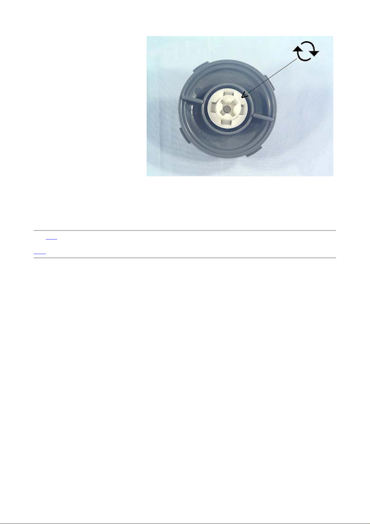
The liquidiser blade hub assembly
viewed from below. Turn the coupling
in a clockwise direction to remove.
30/04/2009http://www.kenwoodservice.co.uk/product-files-kar/guide_FP250.htm
Page 7
Page 7 of 7Spares - FP250 Disassembly & re-assembly instructions
Click here to return to the top of the page.
Back.
30/04/2009http://www.kenwoodservice.co.uk/product-files-kar/guide_FP250.htm
 Loading...