

SOME NOTIONS ON
HUMIDITY
Air always contains a certain amount of water in
the form of vapour. This determines the level of
humidity in an atmosphere.
The capacity of the air to hold water vapour
increases with temperature.
This is why in our homes, as soon as the temperature decreases, the vapour contained in the air
condenses, as is evident on the colder surfaces
in the room, such as the windows, walls etc.
The purpose of a dehumidifier is to remove the
excess moisture from the air, avoiding the dama-
ge caused by condensation.
Experts have established that the optimum envi-
ronmental conditions for our well being and for
the home are obtained between 40% and 60%
relative humidity.
With very low temperatures, you are recommended to heat the room even minimally.
This considerably increases the dehumidifying
power of the appliance.
With heating, the condensation formed by the
water vapour on windows and other cold surfaces evaporates into the air to be collected by the
dehumidifier. Air leaving the dehumidifier is
usually warmer than room temperature.
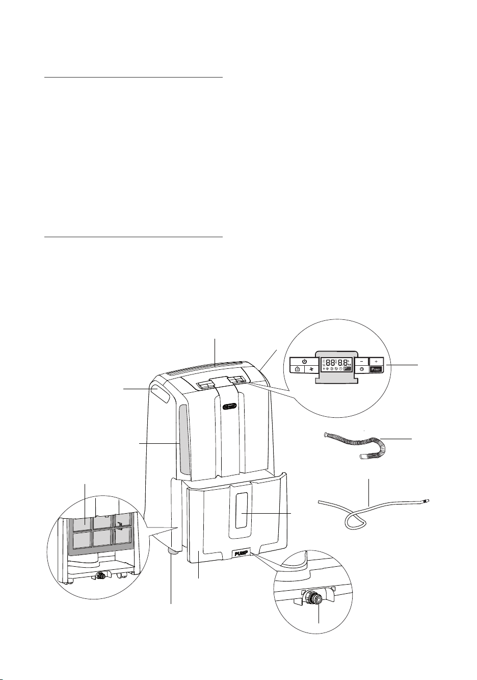
DESCRIPTION/ACCESSORIES
1. Control panel
2. Water level viewing window
3. Condensate collection tank
4. Lifting handles
5. Air intake grille
6. Air filter
7. Air outlet grille
8. Condensate drain hose to be inserted in the
back of the appliance
9. Pump condensate drain hose to be inserted
in the front of the appliance
10. Pump connector (remove cap before use)
11. Castors
4
5
6
7
4
1
8
9
2
11
3
10
8
EN
INSTALLATION
Position the appliance in the room to be dehumidified.
A free space of at least 50 cm must be left at the
front of the dehumidifier, so as not to block the air
outlet.
For efficient ventilation a space of about 5-10 cm
should be left at the back of the appliance.
The condensate can be drained in three ways:
fig. 4
A)) Draining into the ta
The condensate can be drained directly into the
tank.
The tank can be easily removed (fig.1).
When the tank is full, remove and empty into a
sink or bath, then put back correctly.
Please note: The tank must be positioned correctly. An intermittent beep means the tank is not
correctly positioned.
fig. 1
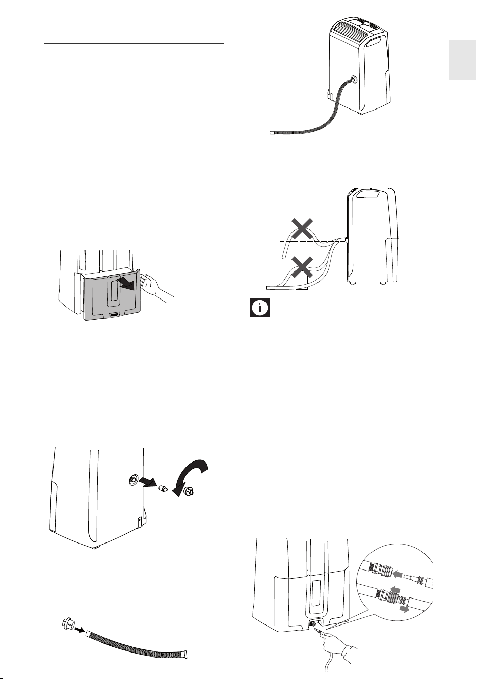
B) Continuous external draining
If the appliance is to be operated for long periods
but you are unable to empty the tank regularly,
you are recommended to use the continuous
drain facility.
1) Remove the protective cap 1 by turning it anticlockwise then remove the rubber cap 2 from
the spout (fig. 2).
2
1
fig. 2
3) Make sure the end of the hose is no higher
than the spout (fig. 5) or water could remain
in the tank. Make sure there are no kinks in
the hose.
NO
NO
fig. 5
YES
Please note:
the spout when the continuous drain function is
not in use.
Keep the rubber cap to close
C) Continuous drain with pump (certain models only)
Thanks to the exclusive condensate drain system,
the hose (9) can be used to drain condensate with
a difference in level of up to 4 m between the end
of the hose and the outlet.
For pump assisted drainage, connect the hose
provided (9) to the connection on the bottom of
the appliance (fig. 6). Select the dehumidifying
function and press the pump button.
Please note: If the condensate hose is not in
place and the pump is enabled, the message
PUMP will flash. To eliminate the problem:
• Check that the hose is correctly positioned
• Unplug the appliance from the mains and plug
in again
2) Insert the protective cap 1 on the condensate
drain hose (8) as far as it will go (fig. 3), then
screw the protective cap back onto the spout
(fig. 4).
fig. 3
1 PUSH
2
9
fig. 6
 Loading...