

Page 1
Gebrauchsanweisung
User manual
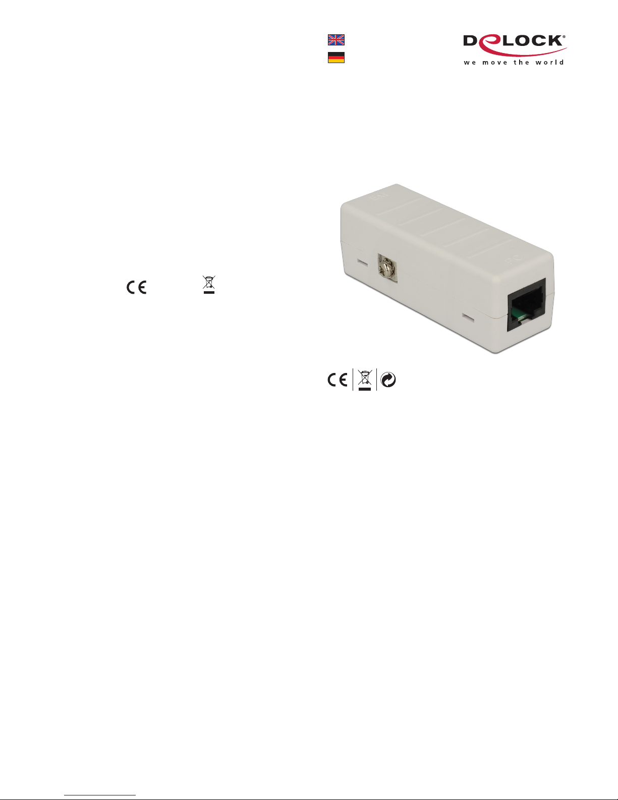
62619:
Network Isolator 6 kV RJ45
62620:
Network Isolator 6 kV RJ45
with PoE
Product-No:62619-62620
User manual no:62619-a
www.delock.com
Declaration of conformity
Products with a CE symbol fulfill the RoHS directive (2011/65/EU), which were
released by the EU-comission.
The declaration of conformity can be downloaded here:
http://www.delock.de/service/conformity
WEEE-notice
The WEEE (Waste Electrical and Electronic Equipment)-directive, which became
effective as European law on February 13th 2003, resulted in an all out change
in the disposal of disused electro devices. The primarily purpose of this directive
is the avoidance of electrical waste (WEEE) and at the same time the support of
recycling and other forms of recycling in order to reduce waste. The WEEE-logo
on the device and the package indicates that the device should not be disposed
in the normal household garbage. You are responsible for taking the disused
electrical and electronical devices to a respective collecting point. A separated
collection and reasonable recycling of your electrical waste helps handling the
natural resources more economical. Furthermore recycling of electrical waste is
a contribution to keep the environment and thus also the health of men. Further
information about disposal of electrical and electronical waste, recycling and
the collection points are available in local organizations, waste management
enterprises, in specialized trade and the producer of the device.
EU Import: Tragant Handels- und Beteiligungs GmbH
Beeskowdamm 13/15, 14167 Berlin, Germany
Page 2

English
Description
The Delock RJ45 Isolator protects the network connection of a device against
overvoltage. The compact device supports Ethernet with 10/100/1000 Mb/s.
Specification
• Connector:
1 x RJ45 female (device)
1 x RJ45 female (extern)
1 x screw terminal for equipotential bonding
• Data transfer rate up to 10/100/1000 Mb/s
• 6 kV Isolation (10 / 700 us)
• Housing material: plastic
• Dimensions (LxWxH): ca. 70 x 25 x 25 mm
Only 62620:
• Supports PoE devices
System requirements
• Device with a free RJ45 port
• Network cable (max. 50 cm)
Package content
• Isolator
• User manual
Safety instructions:
• Protect the product against moisture
• Protect the product against direct sunlight
Installation
1.
Switch off all power connections to the connected Ethernet devices.
2.
Connect the RJ45 cable from external side to the RJ45 port marked “
Ext
”.
3.
Connect the RJ45 cable from the internal, to be protected device, to the RJ-45
port marked “PC”. The internal cable should be as short as possible.
4.
Connect the ground wire to the screw terminal.
Important:
Make sure the
isolator is securely grounded. This allows excess current to flow to ground.
5.
Switch on power connections to the Ethernet devices.
Support Delock
If you have further questions, please contact our customer support
support@delock.de
You can find current product information on our homepage: www.delock.com
Final clause
Information and data contained in this manual are subject to change without
notice in advance. Errors and misprints excepted.
Copyright
No part of this user manual may be reproduced, or transmitted for any purpose,
regardless in which way or by which means, electronically or mechanically,
without explicit written approval of Delock.
Edition: 01/2015
Deutsch
Kurzbeschreibung
Der Delock RJ45 Isolator schützt die Netzwerkverbindung eines angeschlossenen
Gerätes vor Überspannung. Der kompakte Adapter unterstützt Ethernet mit
10/100/1000 Mb/s.
Technische Daten
• Anschlüsse:
1 x RJ45 Buchse (Gerät)
1 x RJ45 Buchse (extern)
1 x Schraubklemme für Potentialausgleich
• Datentransferrate bis zu 10/100/1000 Mb/s
• 6 kV Isolation (10 / 700 us)
• Gehäusematerial: Kunststoff
• Maße (LxBxH): ca. 70 x 25 x 25 mm
Nur 62620:
• Geeignet für PoE Geräte
Systemvoraussetzungen
• Gerät mit einem freien RJ45 Port
• Netzwerkkabel (max. 50 cm)
Packungsinhalt
• Isolator
Sicherheitshinweise:
• Produkt vor Feuchtigkeit schützen
• Produkt vor direkter Sonneneinstrahlung schützen
Installation
1.
Schalten Sie die Stromversorgung von allen verbundenen Ethernet Geräten
aus.
2.
Verbinden Sie das RJ45 Kabel von der externen Seite mit der RJ45 Buchse
die “
Ext
” beschriftet ist.
3.
Verbinden Sie das RJ45 Kabel vom internen, zu schützenden Gerät mit der
RJ45 Buchse die “PC” beschriftet ist. Das interne Kabel sollte dabei so kurz
wie möglich sein.
4.
Verbinden Sie das Erdungskabel mit dem Schraubanschluss.
Wichtig:
Stellen
Sie sicher, dass der Isolator geerdet ist. Dies ermöglicht die Ableitung der
Überspannung.
5.
Schalten Sie die Stromversorgung der angeschlossenen Geräte wieder an.
Support Delock
Bei weitergehenden Supportanfragen wenden Sie sich bitte an
support@delock.de
Aktuelle Produkti nfor mati onen und Treiber Downloads finden Sie auch auf
unserer Homepage: www.delock.de
Schlussbestimmung
Die in diesem Handbuch enthaltenen Angaben und Daten können ohne vorherige
Ankündigung geändert werden. Irrtümer und Druckfehler vorbehalten.
Copyright
Ohne ausdrückliche schriftliche Erlau bnis von Deloc k darf kein Teil dieser
Bedienungsanleitung für irgendwelche Zwecke vervielfältigt oder übertragen
werden, unabhängig davon, auf welche Art und Weise oder mit welchen Mitteln,
elektronisch oder mechanisch, dies geschieht.
Stand: 01/2015
 Loading...