

Page 1
User manual
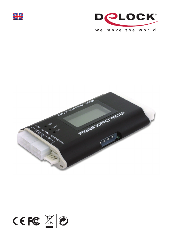
Power supply tester III
Product-No:18159
User manual No:18159-b
www.delock.com
Page 2

Description
The Delock Power supply tester is a robust voltage tester for PC-power supply.
ATX, BTX and ITX compliant power supplies can be tested. The device shows on
one display all supply voltage with one decimal place. Errors will be announced
by a warn signal. The PC/SPS is suitable for the ambitious hobby user, as well as
for a quick functional check in specialized trade.
Specification
• Voltage source: 20/24 pol. (ATX-connector)
• Voltage test: +12V, -12V, +5V, +3,3V
5V Stand By (SB)
12V Power Good (PG)
• Connectors: Floppy, HDD, CDROM, SATA, 4 pin (P4), 8 pin (Dual-CPU), 6 pin
(PCI-Express)
Package content*
• Power supply tester III
• User manual
*Make sure that the product package contains all items before operation. If any
item is missing or damaged, then please contact your dealer immediately.
Notice: Do not connect the powers supply to your PC while testing!
1. Plug-in 20/24 pin connector to the Power Tester.
2. Switch on your power supply.
3. Check the voltage in the display.
4. Connect P4 connector to the P4 female connector of the Power Tester.
5. Check the voltage in the display.
6. Plug-in the HDD cable.
The LED’s +12V and +5V should light up.
7. Remove the HDD cable.
8. Plug-in a Floppy cable.
9. The LED’s +12V and +5V should light up.
10. Remove the Floppy cable.
11. Plug-in a SATA cable.
12. The LED’s +12V, +3.3V and +5V should light up.
13. Remove the SATA cable.
14. Plug-in 6 pin and 8 pin connector one after the other.
15. Check the voltage in the display.
-2-
Page 3

16. If the LED’s are not lightning, than the power supply is damaged.
Support Delock
If you have further questions, please contact our customer support
support@delock.de
You can find current product information on our homepage:
www.delock.com
Final clause
Information and data contained in this manual are subject to change without
notice in advance. Errors and misprints excepted.
Copyright
No part of this user manual may be reproduced, or transmitted for any purpose,
regardless in which way or by which means, electronically or mechanically,
without explicit written approval of Delock.
Edition: 12/2008
-3-
 Loading...