

Del Morino Rotex 90, Rotex 150, Rotex 110, Rotex 130, Rotex 170 Manual Of Use And Maintenance
...Page 1

Rotex-e-06 Manual of use and maintenance : Rotex
Del Morino srl , v.Caroni di Sotto 19,
I-52033 Caprese Michelangelo AR Italy
Ph: +39-575-791059 Fax: +39-575-791210
E.mail: export@del-morino.it
http://www.del-morino.it
MANUAL OF USE AND MAINTENANCE
ROTARY HARROW ROTEX
Page 2

2
PREFACE
This manual is an integral p art of the machine.
It must always accompany the machine and be kept within reach of the operator.
The enclosures mentioned are on integral part of this manual.
The purpose of this manual.
This manual gives information for the correct and safe use of the machine.
The owner must read this manual carefully before work with the machine.
Responsibility of the o wner
The owner is responsible for acc idents or dam ages c aused to people or things due to negligence in following
the instructions in this manual.
Assistance in using this manual
Explanations: contact the dealer.
Request for additional copies of the manual: in case of loss or wear and tear, or in case one wants the
manual in a different language, the customer should ask the dealer or manufacturer.
Pay attention to the warning signals
<Danger>: indicates a situation that is potentially dangerous which, if not avoided, will cause death or
serious
damage.
<Warning>: indicates a situation that is potentially dangerous which, if not avoided, will cause death or
serious damage.
<Caution>: indicates a situation that is potentially dangerous which, if not avoided, can cause minor to
moderate damage or it indicates to be careful about an unsafe procedure.
<Important>: indicates instructions that must be followed precisely in order to avoid damage to the product,
process
or environment.
<Note>: indicates supplementary information.
Page 3

3
DESCRIPTION
FUNCTION OF USE
The machine, thanks to the large r ange of types m odels and vers ions all c onf igurable through many available
variants according to specific requirement, carries out all the func tion related with tools rotation in various
work environment (open field, vineyards, orchards, flower gardens, parks, vegetable gardens) , in all type of
ground whatever its composition (sandy soil, medium mixture, clay) and consistency (crumbly, hard, semiplastic) may be.
The use of a technical constr uctive conc ept tr ended to the s earc h of high perf ormances, reduction of troubles
and durability, improves the power/consumption ratio of the tractor thanks to the elasticity of the machine
frame, to the tools shape and to many original technical solutions.
PERFORMANCES
The machine is connected to the tr actor by a 3° point hitch which gives a movement of translation and a
cardan shaft connected to the PTO which gives a movement of translation to the tools carrier.
The working width is fix and it is determined by the choice of the machine type.
The working depth is adjustable by a rear roller.
The working area is fix.
PERFORMANCE LIMITS
Maximum forwarding speed: 5 km/h.
Speeds higher than the m aximum can comprom ise the condition of the m achine, the quality of the work
and the safety of the operator.
Maximum power applicable to the gear box: from 13 to 59 kW ± 5% at 540 g/m in depending from the
models.
Higher power than one indicated, can damage irreparably the transmiss ion gear box; especially during
heavy works.
Maximum working depth: from 180 to 210 mm depending from the model.
STANDARD FEATURES
- Shear bolt cardan shaft.
VARIANTS & ACCESSORIES
- Wire roller.
- Cage roller.
- Spiked roller.
- Levelling blade.
- Seeder (110÷250).
Page 4

4
TECHINICAL SPECIFICATIONS
CHARACTERISTICS FOR MODEL
Model
Type
Power
Working width
Weight Maximum working
depth
Total width
N° of tools
HP KW cm. inch Kg. lbs. cm. inch cm. inch n°
rotors
n°
teeth
ROTEX
90
18-35
13-26
90
35
198
455
18 7 95
37,5 4 8
110
20-40
15-30
110
43
211
465
18 7 115
45,3 5 10
130
25-45
18-33
130
52
226
498
18 7 135
53,1 6 12
150
30-50
22-38
150
60
248
546
18 7 155
60,9 7 14
170 30-80 22-59 170 67 295 650 21 9 175 68,7 8 16
190
40-80
30-59
190
75
320
705
21 9 195
76,5 9 18
230
50-80
38-59
230
90
415
914
21 9 235
92,1
11
22
250
60-80
44-59
250
99
440
970
21 9 255
100
12
24
Page 5

5
SAFETY INFORMATION
GENERAL REGULATIONS
Only work in daylight.
To prevent damage due to lunch of objects or parts of blades, before to start job be sure that any
persons or animals should be in the radius of 50 meters from the machine.
Wear long pants and heavy shoes.
The protections are integral part of the machine: always work with the protections.
Make sure that the 4 wheels of all components be adjusted to the same cutting height.
Pay attention to the soil: make sure that are not stones, sticks, iron wires, etc…
Pay attention using the machine on slopes: proceed to the maxim um slope and never work in slanting
direction.
Before leaving the driver's seat, turn off the engine and disengage the transmission engine-shaft.
Check immediately the machine if it touches foreign objects.
Check immediately the machine if there are unusual strong vibrations.
Change quickly defective parts.
SAFETY RESTRICTIONS
Children and people who are not familiar with these instructions must not be permitted to use the machine.
Local regulations can restrict the use of the machine in accordance to the age.
Page 6

6
SAFETY SIGNS ON THE MACHINE
In this section, the safety signs on the machine are reproduced and explained.
1 2 3 4 5 6
1. Read the operator manual.
2. Disconnect the tractor key before maintenance and repair operations.
3. Stay at safety distance from blades when machine is moving.
1. Danger of flying objects. Stay at safety distance.
4. Stay at safety distance from blades when machine is moving.
5. Stay at safety distance from blades when machine is moving.
The safety signs on the machine must always be legible.
In case of damage, the labels of the signs must be replaced.
In the case of machine replacement parts that have safety signs, the signs must be replaced.
Supplying of new safety labels and the applica tion procedure
Contact your dealer to receive new safety labels with instructions for application.
Page 7

7
INSTRUCTIONS FOR USE
BEFORE BEGINNING WORK
a) Connect the machine to the tractor as follows :
1. Insert the lifting arms of the tractor in the lower attachment points of the machine, lock by safety pin.
2. Connect the tractor linkage to the 3° point hitch of the m achine (triangle vertex), insert the pin and
lock with safety pin.
b) Check the gearbox and transmission oil level.
c) With the machine raised, go to the working area.
d) Connect the tractor PTO to the machine PTO.
e) Check that PTO chain is locked to prevent the protection sheet of PTO rotating.
BEGINNING WORK
a) Keep people and animals at least 65 feet radius all around the machine.
b) Pull down the machine until the hoes touch the ground.
c) Connect PTO power and gradually bring it to 540 r.p.m...
d) Pull down completely the machine and start to work.
AT THE END OF WORK
a) Stop the tractor.
b) Raise the machine until the hoes goes out from ground.
c) Disconnect PTO power.
d) Disconnect tractor PTO from machine PTO.
e) Raise completely the machine
Page 8

8
SEEDER
1. SEEDER SET UP
To empty the hopper, m ove lever “4” f rom pos ition “C” to position “A” . After dis charge of all seed m ove again
lever “4” to position “C”.
Fill the hopper with seed, now it is necessary to make set up of the mac hine considering how many Kg of
seed you want to sow each hectare. Refer to the below table operate as follow:
Seed type
Set up
Lever 1
Set up
Lever 2
Set up
Sluice gate 3
Wheat
10
2
Totally open
Corn - Pea 8 3
Totally open
Hemp - Sorghum
6
2
Totally open
Alfalfa 3 1
Half open
Onion 3 1
Half open
Depending on the type of seed, operate as follow:
1. Unscrew locking knob then adjust Lever “1” in correct position, screw docking knob.
2. Unscrew locking knob then adjust Lever “2” in correct position, screw docking knob...
3. Adjust position of Sluice gate “3” pulling in direction “A” to open or pushing in direction “C” to close.
Repeat adjustment on all Sluice gates.
Page 9

9
To verify weight in Kg that will be sow (generally the weight in Kg per hectare related to each type of seed is
showed on technical sheet of the seed) operate as follow:
Model
Wheel turns
Factor K
110
34
400
130
29
400
150
25
400
170
22
400
190
20
400
230
17
400
250
15
400
Lift the seeder till the two wheels “W” and “W1” can turn free (picture 1).
Place a towel under the seeder spreader to collect the seed.
Turn the drive wheel “W” clock wise as showed by the arrow (picture 2) many times as showed on the above
table (choice your model).
Collect and weight the seed in the towel.
The seed weight multiplied per Factor “K” will be the total weight sowed per hectare.
In case of discrepancy respect to the desired weight, change position of Lever “1” and repeat weight
verification.
Picture 2
Picture 1
Page 10

10
MAINTENANCE INSTRUCTIONS
On diagram "A" the maintenances are indicated with their terms to effect on the machine.
Not follow the scheduled terms can compromise the functionality of the machine and in this case the warranty
is not applicable.
DIAGRAM "A" SCHEDULED MAINTENANCE
FIRST
START
AFTER
10 HOURS
WORK
EVERY
30 H.
EVERY
500 H.
END OF
SEASON
BEGIN
WROK
END
WORK
MACHINE Greasing Greasing Greasing
Cleaning
Greasing
Cleaning
GEARBOX Oil level Fill oil Fill oil
Oil
replacement
TRANSMISSION Oil level Fill oil Oil level
Oil
replacemnet
SCREWS
Locking
Locking
TOOLS
Check
Check
Check
Check
Page 11

11
1.
GREASING
At the scheduled time on diagram “A”, grease point “B”.
Greasing point is equipped with greaser HYDRAULIC TYPE MODEL "A" UNI 7663.
To greasing use only MULTIFUNCTIONAL GREASE LITHIUM BASED Type NLGI 2.
2.
OIL LEVEL – OIL REPLACEMENT IN GEARBOX
At the scheduled time on diagram “A” verify the level and replace oil in the gearbox.
To fill oil use only OIL SAE 140 EP.
Gearbox capacity: 1,1 L (Rotex 90-110-130-150), 2,5 L (Rotex 170-190-230-250).
a) To check the oil level in gear box, operate as follows :
1. With the machine on level unscrew the level plug "B" and check that oil touches lower hole rim.
2. If the level it's ok screw and lock plug "B".
3. If the level it's low, unscrew plug "A" and fill oil.
4. When the level it's ok screw and lock plugs "A" and "B".
b) To replace oil in the gearbox, operate as follows:
1. With the machine on level unscrew the level plugs “C”, "D" and “E” and drain completely oil.
2. Screw the plug “E”.
3. Fill new oil through the hole “D” up to oil touches lower hole rim “C”.
4. When the level is ok, screw the plugs “C” and “D”.
3. OIL LEVEL – OIL TRANSMISSION REPLACEMENT
At the scheduled time on diagram "A" check the level or replace oil in the transmission.
To fill oil use only OIL SAE 140 EP.
Tank capacity: from 3,6 L to 12,5 L depending from the model.
Page 12

12
c) To check the oil in the transmission, operate as follows:
1. With the machine on level unscrew the plug "B" and check that oil touches lower hole rim.
2. If the level is ok, lock the plug "B".
3. If the level is low, fill oil.
4. When the level is ok, lock the plug “B”.
d) To replace oil in the transmission, operate as follows:
1. Unscrew the plug “B”, turn backward the machine and drain completely oil.
2. Introduce the new oil through the hole “B” up to oil touches lower hole rim.
3. When level is ok, lock the plug “B”.
4. TOOLS REPLACEMENT
a) To replace the tools, operate as follows:
1. Unscrews the two screws "A" which lock the tools to replace.
2. Take out the two screws and remove the tool “B”.
3. Place the new tool and the two screws “A”.
4. Lock the screws "A" with pneumatic wrench.
5. Repeat this operation for all the tools to replace.
ATTENTION: each rotor is equipped with a couple of right and left tools according to the position,
don’t invert the right tools with the left one s.
Page 13

13
PROBLEMS SOLVING
TROUBLES CAUSES AND SOLUTIONS
Insufficient working depth
-Decrease the forwarding speed
-Tools are not sharpened or damaged
Tools don’t penetrate
Rotary harrow bounces on the round and vibrates
-Broken or damaged tools
-Check the tools assembling
-Foreign objects between hoes - clean
-Decrease the forwarding speed
-Soil too dry and hard
Rotor compactness, obstruction
-Soil too wet
-Reduce working depth
-Increase number of revolutions of the rotor
Excessive tilling of the soil
-Increase forwarding speed
- Decrease number of revolutions of the rotor
Poor tilling of the soil
- Decrease the forwarding speed
-Increase number of revolutions of the rotor
Page 14

14
TRANSPORT
Except when working, moving the machine takes place when the machine is standing still and the
transmission is disconnected.
<Important>: keep speed low avoiding holes and ground roughness.
<Note> when on the road, obey existing traff ic laws. Exhibit the signal signs on the rear ends. Respect
any local laws there may be.
<Note> Lock the lifting bars of the tractor with the chain and tightners. They must be parallel to the bars.
STORAGE
Store the machine in a dry place that isn't dusty.
INFORMATION ON DEMOLITION
At the end of its working life, the machine m ust be sent to be demolished and that can only be
done by an authorized authority, in accordance with the national laws in force for the environment.
Therefore it is necessar y to get information f rom the qualified local author ities on the procedur e to follow.
The machine is mainly composed of: iron materials and paints.
WARRANTY
The machine is covered by the manufacturer warranty for a period of 24 months.
The warranty is not applicable when:
a) The maintenance work has not been done correctly.
b) The machine has been used out of its own service.
c) The machine has been transformed or modified without the manufacturer's written authorization.
Page 15

15
WORK AND MAINTENANCE SHEET
Every user should register on this sheet the facts about the life of the m achine (both work and m aintenance) ,
so as to attest its conditions.
DATE
WORKING
HOURS
MAITENANCE
NOTE
USER
Page 16

16
SPARE PART AND ACCESSORIES
Page 17

17
ROTEX MECHANISMS 90-110-130-150
Page 18

18
ROTEX MECHANISMS 170-190
Page 19

19
ROTEX MECHANISMS 230-250
Page 20

20
ROTEX SHEET 90-110-130-150
Page 21

21
ROTEX SHEETS 170-190
Page 22

22
ROTEX SHEETS 230-250
Page 23

23
LEVELLING BLADE ROTEX 90-110-130
LEVELLING BLADE ROTEX 150
LEVELLING BLADE ROTEX 170-190-230-250
Page 24

24
ROTEX ROLLER LIFTING 110-130-150-170-190-230-250
ROTEX WIRE ROLLER
Page 25
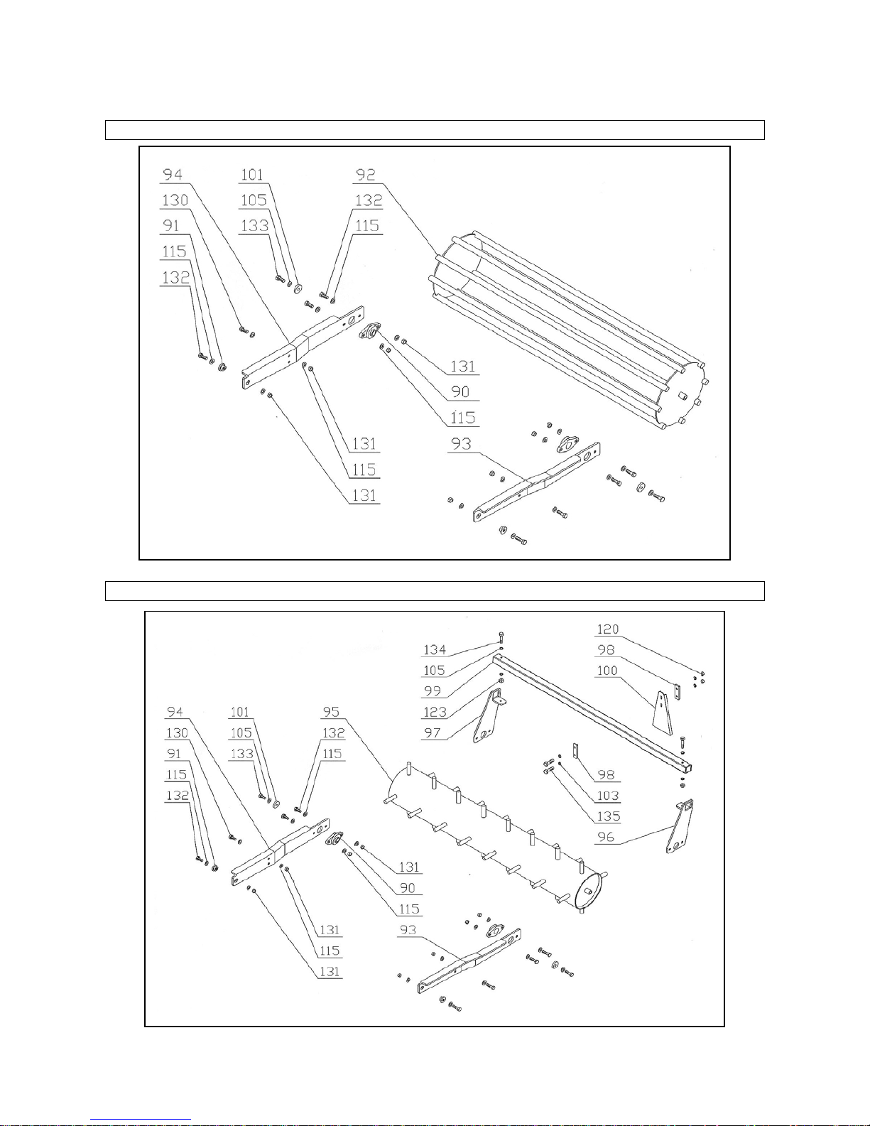
25
ROTEX CAGE ROLLER
ROTEX SPIKED ROLLER
Page 26

26
SEEDER HOLDER
Page 27

27
SPARE PARTS LIST ROTEX
Pos Code Description
Quantity
90
110
130
150
170
190
230
250
1
42000002
GEARBOX
1 1 1 1 1 1 2
42000027
GEARBOX
1 1 3
42400008
UCFC 206 SUPPORT
3 4 5 6 7 8 10
11 4 42400009
UCFC 208 SUPPORT
1 1 1 1 1 1 5
42400010
UCFC 209 SUPPORT
1 1 6
41000038
BEARING 6307
1 1 1 1 1 1 7
41000039
BEARING 6208
3 4 5 6 7 8 11
12 8 41100013
OIL SEAL 80x45x10
8
10
12
14
16
18
20
22 9 41100014
OIL SEAL 80x55x10
2 2 10
41200008
ORING 330
3 4 5 6 7 8 10
11
11
ERP165D
SEAL
4 5 6 7 12
ERP449D
SEAL 8 9
11
12
13
ERP166D
SEAL
3 4 5 6 7 8 10
11
14
ERP164D
SEAL
1 1 1 1 1 1 15
ERP450D
SEAL 1 1
16
40400003
SEEGER Ø80 UNI 7437
4 5 6 7 8 9 11
12
17
41900005
SAFETY PROTECTION
1 1 1 1 1 1 1 1 18
ERP062VD
SIDE BLADE HOLDER
3 4 5 6 7 8 10
11
19
ERP403VD
CENTRAL BLADE HOLDER
1 1 1 1 1 1 20
ERP446VD
CENTRAL BLADE HOLDER
1 1 21
ERP153VD
SIDE HUB
3 4 5 6 22
ERP152VD
CENTRAL HUB
1 1 1 1 23
ERP451VD
SIDE HUB
7 8 11
12
24
ERP452VD
CENTRAL HUB
1 1 25
ERP157D
SAFETY WASHER
3 4 5 6 7 8 10
11
26
ERP156D
CENTRAL SHAFT
1 1 1 1 1 1 27
ERP410D
CENTRAL SHAFT
1 1 28
ERP301D
GEAR H 25
4 5 6 7 8 9 29
ERP406D
SIDE GEAR H 30
10
11
30
ERP405D
CENTRAL GEAR H 30
1 1 31
ERP302D
GEAR BUSH H 25
4 5 6 7 8 9 32
ERP154D
GEAR BUSH H 30
11
12
33
ERP326ZD
SUPPORT CAP UCFC 206
3 4 5 6 7 8 10
11
34
ERP360ZD
SUPPORT CAP UCFC 208
1 1 1 1 1 1 35
ERP411ZD
SUPPORT CAP UCFC 209
1 1 36
ERP303D
RIGHT TOOTH L=180
4 4 6 8 37
ERP304D
LEFT TOOTH L=180
4 6 6 6 38
ERP162D
RIGHT TOOTH L=220
8 8 39
ERP163D
LEFT TOOTH L=220
8
10
40
ERP447D
RIGHT/LEFT TOOTH L=280
12
12
41
ERP447D
RIGHT LEFT/TOOTH L=280
10
12
42
ERP051AVD
MAIN FRAME 90
1 42
ERP051BVD
MAIN FRAME 110
1 42
ERP051CVD
MAIN FRAME 130
1 42
ERP051DVD
MAIN FRAME 150
1 42
ERP051EVD
MAIN FRAME 170
1 42
ERP051FVD
MAIN FRAME 190
1 42
ERP051GVD
MAIN FRAME 230
1 42
ERP051HVD
MAIN FRAME 250
1 43
ERP052AVD
COVER 90
1 43
ERP052BVD
COVER 110
1 43
ERP052CVD
COVER 130
1
Page 28

28
Pos Code Description
Quantity
90
110
130
150
170
190
230
250
43
ERP052DVD
COVER 150
1 43
ERP052EVD
COVER 170
1 43
ERP052FVD
COVER 190
1 43
ERP052GVD
COVER 230
1 43
ERP052HVD
COVER 250
1 44
ERP436VD
LEFT TAIL BOARD
1 1 1 1 1 1 1 1 45
ERP417VD
RIGHT TAIL BOARD
1 1 1 1 1 1 1 1 46
ERP056VD
SUPPORT
1 1 1 1 47
ERP322VD
LOWER HITCH
2 2 2 2 48
ERP055VD
GEARBOX SUPPORT
1 1 1 1 1 1 49
ERP341VD
GEARBOX COVER
1 1 1 1 1 1 50
ERP053VD
III POINT HITCH
1 1 1 1 50
ERP054VD
III POINT HITCH
1 1 51
ERP057AVD
FRONT PIPE 170
1 51
ERP057BVD
FRONT PIPE 190
1 53
ERP349VD
LOWER HITCH HOLDFAST
2 2 54
ERP058VD
LOWER HITCH
2 2 55
42500024
COVER SEAL 90
1 55
42500025
COVER SEAL 110
1 55
42500026
COVER SEAL 130
1 55
42500027
COVER SEAL 150
1 55
42500028
COVER SEAL 170
1 55
42500029
COVER SEAL 190
1 55
42500034
COVER SEAL 230
1 55
42500035
COVER SEAL 250
1 56
ERP063AVD
FRONT PIPE 230
1 56
ERP063BVD
FRONT PIPE 250
1 57
ERP064VD
III POINT LEFT SUPPORT
1 1 58
ERP065VD
III POINT RIGHT SUPPORT
1 1 59
ERP066VD
GEARBOX SUPPORT
1 1 60
ERP424VD
GEARBOX SUPPORT
1 1 61
ERP426VD
LEFT SIDE III POINT
1 1 62
ERP427VD
RIGHT SIDE III POINT
1 1 63
ERP067VD
III POINT BEAM
1 1 64
ERP068VD
LEFT REIFORCEMENT
1 1 65
ERP069VD
RIGHT REINFORCEMENT
1 1 66
ERP366VD
SUPPORT HOLDFAST
2 2 2 2 67
ERP073VD
LOWER HITCH
2 2 68
43700012
III POINT PIN
1 1 1 1 1 1 69
SRM220D
COMPLETE PIN I CATEGORY
2 2 2 2 70
43700010
I CATEGORY PIN
2 2 71
ERP082ZD
III POINT PIN
1 1 72
ERP083ZD
PIN II CATEGORY
2 2 73
SRM233ZD
BUSH
4 4 4 4 4 4 4 4 74
ERP330AVD
LEVELLING BLADE 90
1 74
ERP330BVD
LEVELLING BLADE 110
1 74
ERP330CVD
LEVELLING BLADE 130
1 74
ERP330DVD
LEVELLING BLADE 150
1 74
ERP330EVD
LEVELLING BLADE170
1 74
ERP330FVD
LEVELLING BLADE 190
1 74
ERP330GVD
LEVELLING BLADE 230
1 74
ERP330HVD
LEVELLING BLADE 250
1 75
ERP331VD
BLADE SUPPORT
2
76
URC181ZD
LIFTING BRACKET
1 1 77
ERP060VD
BLADE ARM
2 2 2 2 2 2 2
2
Page 29

29
Pos Code Description
Quantity
90
110
130
150
170
190
230
250
78
ERP333VD
BLADE ARM HOLDFAST
2 2 2 2 2 2 2 2 79
ERP363VD
BLADE LEFT SUPPORT
1 1 79
ERP465VD
BLADE LEFT SUPPORT
1 1 80
ERP364VD
BLADE RIGHT SUPPORT
1 1 80
ERP466VD
BLADE RIGHT SUPPORT
1 1 81
ERP061VD
BLADE ARM HITCH
2 2 2 2 82
ERP442VD
REAR TIR ROD HITCH
2 2 2 2 2 2 2 83
ERP086VD
LEFT TIE ROD FRONT HITCH
1 1 1 83
ERP074VD
LEFT TIE ROD FRONT HITCH
1 1 1 1 84
ERP087VD
RIGHT TIE ROD FRONT HITCH
1 1 1 84
ERP075VD
RIGHT TIE ROD FRONT HITCH
1 1 1 1 85
41800010
TIE ROD
2 2 2 2 2 2 2 86
ERP336AVD
SCRAPER 90
1 86
ERP336BVD
SCRAPER 110
1 86
ERP336CVD
SCRAPER 130
1 86
ERP336DVD
SCRAPER 150
1 86
ERP336EVD
SCRAPER 170
1 86
ERP336FVD
SCRAPER 190
1 86
ERP336GVD
SCRAPER 230
1 86
ERP336HVD
SCRAPER 250
1 87
ERP070AVD
WIRE ROLLER 90
1 87
ERP070BVD
WIRE ROLLER 110
1 87
ERP070CVD
WIRE ROLLER 130
1 87
ERP070DVD
WIRE ROLLER 150
1 87
ERP070EVD
WIRE ROLLER 170
1 87
ERP070FVD
WIRE ROLLER 190
1 87
ERP070GVD
WIRE ROLLER 230
1 87
ERP070HVD
WIRE ROLLER 250
1 88
ERP076VD
WIRE ROLLER LEFT ARM
1 1 1 1 1 1 1 1 89
ERP077VD
WIRE ROLLER RIGHT ARM
1 1 1 1 1 1 1 1 90
42400006
SUPPORT UCFL 205
2 2 2 2 2 2 2 2 91
ERP328ZD
BUSH
2 2 2 2 2 2 2 2 92
ERP071AVD
CAGE ROLLER 90
1 92
ERP071BVD
CAGE ROLLER 110
1 92
ERP071CVD
CAGE ROLLER 130
1 92
ERP071DVD
CAGE ROLLER 150
1 92
ERP071EVD
CAGE ROLLER 170
1 92
ERP071FVD
CAGE ROLLER 190
1 92
ERP071GVD
CAGE ROLLER 230
1 92
ERP071HVD
CAGE ROLLER 250
1 93
ERP078VD
LEFT ARM CAGE+SPIKED ROLLER
1 1 1 1 1 1 1 1 94
ERP079VD
RIGHT ARM CAGE+SPIKED ROLLER
1 1 1 1 1 1 1 1 95
ERP072AVD
SPIKED ROLLER 90
1 95
ERP072BVD
SPIKED ROLLER 110
1 95
ERP072CVD
SPIKED ROLLER 130
1 95
ERP072DVD
SPIKED ROLLER 150
1 95
ERP072EVD
SPIKED ROLLER 170
1 95
ERP072FVD
SPIKED ROLLER 190
1 95
ERP072GVD
SPIKED ROLLER 230
1 95
ERP072HVD
SPIKED ROLLER 250
1 96
ERP080VD
LEFT SUPPORT SCRAPERS
1 1 1 1 1 1 1 1 97
ERP081VD
RIGHT SUPPORT SCRAPERS
1 1 1 1 1 1 1 1 98
ERP433VD
SCRAPERS PLATE
8
10
12
14
16
18
22
24
99
ERP434AVD
SCRAPERS BEAM 90
1 99
ERP434BVD
SCRAPERS BEAM 100
1
Page 30

30
Pos Code Description
Quantity
90
110
130
150
170
190
230
250
99
ERP434CVD
SCRAPERS BEAM 130
1 99
ERP434DVD
SCRAPERS BEAM 150
1 99
ERP434EVD
SCRAPERS BEAM 170
1 99
ERP434FVD
SCRAPERS BEAM 190
1 99
ERP434GVD
SCRAPERS BEAM 230
1 99
ERP434HVD
SCRAPERS BEAM 250
1 100
ERP431ZD
SCRAPER
4 5 6 7 8 9 11
12
101
HOL214D
ROLL STOPPER
2 2 2 2 2 2 2 2 102
40100197
SCREW M10x45 UNI5739
12
16
20
24
28
32
40
44
103
40300003
WASHER Ø10 UNI 6592
56
68
80
92
96
108
140
152
104
40100102
SCREW M12x50 UNI 5737
4
10
10
10
10
10 6 6
105
40300004
WASHER Ø12 UNI 6592
52
66
66
66
116
116
116
116
106
40100229
SCREW M14x45 PF UNI 5739
16
20
24
28
32
36
107
40300064
WASHER CONTACT Ø14 UNI 7604
16
20
24
28
32
36
44
48
108
40200155
NUT CONELOCK M14 PF DIN 980
16
20
24
28
32
36
44
48
109
40200153
NUT M30x2 DIN 985
1 1 1 1 1 1 1 1 110
40300016
WASHER Ø30 UNI 6592
1 1 1 1 1 1 1 1 111
40200154
NUT M36x3 UNI 5589
3 4 5 6 7 8 10
11
112
40100042
SCREW M8x16 UNI 5739
7 8 9
10
11
12
14
15
113
40300002
WASHER Ø8 UNI 6592
7
22
23
24
25
26
28
29
114
40100145
SCREW M14x55 UNI 5739
4 4 115
40300009
WASHER Ø14 UNI 6592
14
29
29
29
29
29
57
57
116
40100061
SCREW M12x45 UNI 5739
8 8 8 8 4 4 4 4 117
40300007
WASHER Ø20 UNI 6592
4 4 4 4 4 4 4 4 118
40100012
SCREW M10x30 UNI 5739
18
22
26
30
34
38
46
50
119
40100030
SCREW M10x20 UNI 5739
8 8 8 8 8 8 8 8 120
40200003
NUT CONELOCK M10 DIN 980
26
32
38
44
50
56
68
74
121
40100014
SCREW M12X30 UNI 5739
16
16
16
16
48
52
54
58
122
40100015
SCREW M12x35 UNI 5739
6 6 6 6 6 6 123
40200006
NUT CONELOCK M12 DIN 980
16
23
23
23
51
51
57
57
124
ERP368VD
LEFT BLADE SUPPORT
1 1 1 125
40300065
WASHER CONTACT Ø12 UNI 7604
32
36
44
48
126
ERP369VD
RIGHT BLADE SUPPORT
1 1 1 127
40100023
SCREW M12x40 UNI 5739
4 4 4 4 36
36
36
36
128
40100080
SCREW M16x35 UNI 5739
8 8 129
40300006
WASHER Ø16 UNI 6592
8 8 8 8 8 16
16
130
40100018
SCREW M14x40 UNI 5739
2 2 2 2 2 2 16
16
131
40200011
NUT CONELOCK M14 DIN 980
6
10
10
10
10
10
24
24
132
40100158
SCREW M14x45 UNI 5739
6 6 6 6 6 6 6 6 133
40100013
SCREW M12x25 UNI 5739
2 2 2 2 2 2 2 2 134
40100064
SCREW M12x80 UNI 5737
2 2 2 2 2 2 2 2 135
40100045
SCREW M10x80 UNI 5737
8
10
12
14
16
18
22
24
136
41300001
SAFETY PIN Ø10
2 2 2 2 2 2 3 3 137
40100230
SCREW M10x30-10,9 UNI 5739
16
20
24
28
32
36
44
48
138
40300066
WASHER CONTACT Ø10 UNI 7604
16
20
24
28
32
36
44
48
139
ERP084VD
III POINT LEFT SUPPORT
1 1 140
ERP085VD
III POINT RIGHT SUPPORT
1 1 141
ERP458VD
TOOTH SPACER
22
24
142
40100245
SCREW M14x55 PF UNI 5738
44
48
143
40100118
SCREW M18x1500 UNI 5737
2 2 2 143
40100103
SCREW M18x90 UNI 5737
2 2 2 2 144
40200028
NUT M18 DIN 980
2 2 2 2 2 2 2 145
40300020
WASHER Ø18 UNI 6592
2 2 2 4 4 4
4
146 ERP459VD
REAR RIGHT TIE ROD HITCH WIRE
ROLER
1 1 1 1
Page 31

31
Pos Code Description
Quantity
90
110
130
150
170
190
230
250
147
ERP460VD
REAR LEFT TIE ROD HITCH WIRE
ROLER
1 1 1
1
150
INT060BVD
SEEDER FRAME
1 150
INT060CVD
SEEDER FRAME
1 150
INT060DVD
SEEDER FRAME
1 150
INT060EVD
SEEDER FRAME
1 1 1 1 151
ERP091BVD
FRAME 110
1 151
ERP091CVD
FRAME 130
1 151
ERP091DVD
FRAME 150
1 151
ERP091EVD
FRAME 170
1 151
ERP091FVD
FRAME 190
1 151
ERP091GVD
FRAME 230
1 151
ERP091HVD
FRAME 250
1 152
ERP090BVD
SEEDER 110 SPRAYER
1 152
ERP090CVD
SEEDER 130 SPRAYER
1 152
ERP090DVD
SEEDER 150 SPRAYER
1 152
ERP090EVD
SEEDER 170 SPRAYER
1 152
ERP090FVD
SEEDER 190 SPRAYER
1 152
ERP090GVD
SEEDER 230 SPRAYER
1 152
ERP090HVD
SEEDER 250 SPRAYER
1 153
ERP089VD
REAR ROLL RIGHT BRACKET
1 1 1 1 1 1 1 154
ERP088VD
REAR ROLL LEFT BRACKET
1 1 1 1 1 1 1 155
INT062VD
SAFETY PROTECTION
1 1 1 1 1 1 1 156
INT189VD
SAFETY PROTECT. LOWER SIDE
1 1 1 1 1 1 1 157
ERP397VD
SPACER
2 158
INT268D
RIGHT WHEEL BUSH
1 1 1 1 1 1 1 159
INT260D
LEFT WHEEL AXLE
1 1 1 1 1 1 1 160
INT063VD
PIGNONE
1 1 1 1 1 1 1 161
INT264ZD
PINION SPACER
5 5 5 5 5 5 5 162
INT064VD
DOUBLE CROWN
1 1 1 1 1 1 1 163
SRM205ZD
SPACER ≠ 13x25x35
3 3 3 3 3 3 3 164
SRM204ZD
SPACER ≠ 6x25x35
3 3 3 3 3 3 3 165
SRM203ZD
SPACER
2 2 2 2 2 2 2 166
PLASTIC PIPE
11
13
13
15
15
15
15
167
43000018
HOSE CLAMP 32-50
11
13
13
15
15
15
15
168
42500030
PLUG 50x50
2 2 2 2 2 2 2 169
42900001
RUBBER WHEEL Ø210x80
2 2 2 2 2 2 2 170
40800011
CHAIN ASA 41S ½” 67 LINK + JOINT
1 1 1 1 1 1 1 171
42300007
ELASTIC PIN 6x40 UNI 6873
1 1 1 1 1 1 1 172
40200002
NUT CONELOCK M8 DIN 980
7 7 7 7 7 7 7 173
40200059
NUT M14 DIN 982
3 3 3 3 3 3 3 174
40100001
SCREW M8x20 UNI 5739
7 7 7 7 7 7 7 175
40100251
SCREW M12x20 UNI 5931
1 1 1 1 1 1 1 176
40100095
SCREW M12x130 UNI 5737
1 1 1 1 1 1 1 177
40100025
SCREW M14x50 UNI 5739
4 4 4 4 4 4 4 178
40100227
SCREW M8x60 UNI 5737
5 5 5 5 5 5 5 179
40100109
SCREW M14x60 UNI 5737
4 4 4 4 4 4 4 180
40100034
SCREW M16x40 UNI 5739
4 181
40100130
SCREW M 16x60 UNI 5739
4 4 4 4 4 4 182
40200040
NUT M8 DIN 982
5 5 5 5 5 5 5 183
40200008
NUT CONELOCK M16 DIN 980
4 4 4 4 4 4 4 184
42600019
PTO SHAFT IV° CAT. BOLT L=700
1 1 1 1 184
42600110
PTO SHAFT V° CAT. BOLT L=700
1 1 184
42600111
PTO SHAFT VI° CAT. BOLT L=700
1
1
Page 32

32
SEEDER FRAME
Page 33

33
SEEDER MECHANISM
Page 34

34
INDEX
PREFACE
...........................................................................................................................................................2
DESCRIPTION
...................................................................................................................................................3
FUNCTION
OF USE ........................................................................................................................................3
PERFORMANCES
..........................................................................................................................................3
PERFORMANCE
LIMITS ................................................................................................................................3
STANDARD
FEATURES ....................................................................................................................................3
VARIANT
S & ACCESSORIES ..........................................................................................................................3
TECHINICAL SPECIFICATIONS
.......................................................................................................................4
SAFETY INFORMATION
...................................................................................................................................5
GENERAL
REGULATIONS ............................................................................................................................5
SAFETY
RESTRICTIONS ...............................................................................................................................5
SAFETY SIGNS ON THE MACHINE
.................................................................................................................6
INSTRUCTIONS FOR USE
................................................................................................................................7
BEFORE
BEGINNING WORK ........................................................................................................................7
BEGINNING
WORK ........................................................................................................................................7
AT
THE END OF WORK .................................................................................................................................7
SEEDER
.............................................................................................................................................................8
1.
SEEDER SET UP .....................................................................................................................................8
MAINTENANCE INSTRUCTIONS
...................................................................................................................10
DIAGRAM
"A" SCHEDULED MAINTENANCE ..............................................................................................10
1.
GREASING ............................................................................................................................................11
2.
OIL LEVEL – OIL REPLACEMENT IN GEARBOX ...............................................................................................11
3. OIL LEVEL – OIL TRANSMISSION REPLACEMENT ............................................................................11
4.
TOOLS REPLACEMENT ..............................................................................................................................12
PROBLEMS SOLVING
....................................................................................................................................13
TRANSPORT
....................................................................................................................................................14
STORAGE
........................................................................................................................................................14
INFORMATION ON DEMOLITION
..................................................................................................................14
WARRANTY
.....................................................................................................................................................14
WORK AND MAINTENANCE SHEET
.............................................................................................................15
ROTEX MECHANISMS 90-110-130-150
.........................................................................................................17
ROTEX MECHANISMS 170-190
......................................................................................................................18
ROTEX MECHANISMS 230-250
......................................................................................................................19
ROTEX SHEET 90-110-130-150
.....................................................................................................................20
ROTEX SHEETS 170-190
................................................................................................................................21
Page 35

35
ROTEX SHEETS 230-250
................................................................................................................................22
LEVELLING BLADE ROTEX 90-110-130
.......................................................................................................23
LEVELLING BLADE ROTEX 150
....................................................................................................................23
LEVELLING BLADE ROTEX 170-190-230-250
..............................................................................................23
ROTEX ROLLER LIFTING 110-130-150-170-190-230-250
............................................................................24
ROTEX WIRE ROLLER
...................................................................................................................................24
ROTEX CAGE ROLLER
..................................................................................................................................25
ROTEX SPIKED ROLLER
...............................................................................................................................25
SEEDER HOLDER
...........................................................................................................................................26
SPARE PARTS LIST ROTEX
..........................................................................................................................27
SEEDER FRAME
.............................................................................................................................................32
SEEDER MECHANISM
....................................................................................................................................33
 Loading...