

Dell EMC Unity 480, Unity 680F, Unity 480F, Unity 680, Unity 880 Hardware Information Manual
...
Dell EMC Unity™ All Flash and Unity Hybrid
Unity 480/F, Unity 680/F, Unity 880/F
Hardware Information Guide
302-005-520
REV 01

Copyright © 2019 Dell Inc. or its subsidiaries. All rights reserved.
Published June 2019
Dell believes the information in this publication is accurate as of its publication date. The information is subject to change without notice.
THE INFORMATION IN THIS PUBLICATION IS PROVIDED “AS-IS.“ DELL MAKES NO REPRESENTATIONS OR WARRANTIES OF ANY KIND
WITH RESPECT TO THE INFORMATION IN THIS PUBLICATION, AND SPECIFICALLY DISCLAIMS IMPLIED WARRANTIES OF
MERCHANTABILITY OR FITNESS FOR A PARTICULAR PURPOSE. USE, COPYING, AND DISTRIBUTION OF ANY DELL SOFTWARE DESCRIBED
IN THIS PUBLICATION REQUIRES AN APPLICABLE SOFTWARE LICENSE.
Dell, EMC, and other trademarks are trademarks of Dell Inc. or its subsidiaries. Other trademarks may be the property of their respective owners.
Published in the USA.
Dell EMC
Hopkinton, Massachusetts 01748-9103
1-508-435-1000 In North America 1-866-464-7381
www.DellEMC.com
2 Unity 480/F, Unity 680/F, Unity 880/F Hardware Information Guide

CONTENTS
Additional resources 5
Chapter 1
Chapter 2
DPE component descriptions 7
2U, 25-drive DPE component overview........................................................8
DPE front view............................................................................................. 9
System identification tags..............................................................10
DPE rear view.............................................................................................. 11
DPE embedded modules and 4-port cards...................................... 11
DPE I/O module types....................................................................14
DPE power supply.......................................................................... 16
Storage processor assembly internal components.......................................17
Technical specifications 19
Technical specifications............................................................................. 20
Dimensions and weight................................................................................21
Power requirements....................................................................................21
Operating environment requirements......................................................... 22
DPE airflow....................................................................................23
Environmental recovery.................................................................24
Shipping and storage requirements............................................... 24
Shock and Vibration.......................................................................24
Fire suppressant disclaimer........................................................... 25
Air quality requirements.................................................................25
Unity 480/F, Unity 680/F, Unity 880/F Hardware Information Guide 3

CONTENTS
4 Unity 480/F, Unity 680/F, Unity 880/F Hardware Information Guide
Additional resources
DANGER
WARNING
CAUTION
NOTICE
Note
As part of an improvement effort, revisions of the software and hardware are
periodically released. Therefore, some functions described in this document might not
be supported by all versions of the software or hardware currently in use. The product
release notes provide the most up-to-date information on product features. Contact
your technical support professional if a product does not function properly or does not
function as described in this document.
Where to get help
Support, product, and licensing information can be obtained as follows:
Product information
For product and feature documentation or release notes, go to Unity Technical
Documentation at: www.emc.com/en-us/documentation/unity-family.htm.
Troubleshooting
For information about products, software updates, licensing, and service, go to Online
Support (registration required) at: https://Support.EMC.com. After logging in, locate
the appropriate Support by Product page.
Technical support
For technical support and service requests, go to Online Support at: https://
Support.EMC.com. After logging in, locate Create a service request. To open a
service request, you must have a valid support agreement. Contact your Sales
Representative for details about obtaining a valid support agreement or to answer any
questions about your account.
Special notice conventions used in this document
Indicates a hazardous situation which, if not avoided, will result in death or
serious injury.
Indicates a hazardous situation which, if not avoided, could result in death or
serious injury.
Indicates a hazardous situation which, if not avoided, could result in minor or
moderate injury.
Addresses practices not related to personal injury.
Presents information that is important, but not hazard-related.
Additional resources 5

Additional resources
6 Unity 480/F, Unity 680/F, Unity 880/F Hardware Information Guide

CHAPTER 1
DPE component descriptions
l
2U, 25-drive DPE component overview............................................................... 8
l
DPE front view.....................................................................................................9
l
DPE rear view......................................................................................................11
l
Storage processor assembly internal components.............................................. 17
DPE component descriptions 7

Note
DPE component descriptions
2U, 25-drive DPE component overview
The 25-drive DPE is two rack units (U), 8.9 cm (3.5 in.) high, 79.2 cm (31.2 in.) deep,
and includes slots for twenty-five 2.5-in. drives.
The DPE consists of the following components:
l
Drives
l
Midplane
l
Storage processor assembly
l
Power supply module
l
EMI shielding
Drives
Each drive consists of one drive in a carrier. The drive carriers are metal and plastic
assemblies that provide smooth, reliable contact with the enclosure slot guides and
midplane connectors. Each carrier has a handle with a latch and spring clips. The latch
holds the drive in place to ensure proper connection with the midplane. Drive activity
and fault LEDs are located on the front of the enclosure.
SAS and SAS flash drives are supported. The drives are populated in the system from
left to right.
The first four drive slots are reserved for system drives, and should not be removed.
You can visually distinguish between drive types by their different latch and handle
mechanisms and by type, capacity, and speed labels on each drive. You can add or
remove a drive while the DPE is powered on, but you should exercise special care
when removing modules while they are in use. Drives are sensitive electronic
components.
Midplane
The midplane separates the front-facing drives from the rear-facing SP assemblies. It
distributes power and signals to all components in the enclosure. The SP assemblies
and drives plug directly into the midplane.
Storage processor assembly
Each DPE contains two SP assemblies. The SP assembly is the intelligent component
providing the compute capability of the DPE. Acting as the control center, each SP
assembly includes status LEDs.
Storage processor assembly power supply module
Each SP assembly contains a power supply module that connects the system to an
exterior power source. Redundant power supplies can keep the entire DPE running if
one power supply fails. The power supplies include LEDs to indicate component status.
A latch on the module locks it into place to ensure proper connection.
EMI shielding
EMI compliance requires a properly installed electromagnetic interference (EMI)
shield in front of the DPE drives. When installed in cabinets that include a front door,
the DPE includes a simple EMI shield. Other installations require a front bezel that has
a locking latch and integrated EMI shield. Remove the bezel or shield to remove and
install the drives.
8 Unity 480/F, Unity 680/F, Unity 880/F Hardware Information Guide
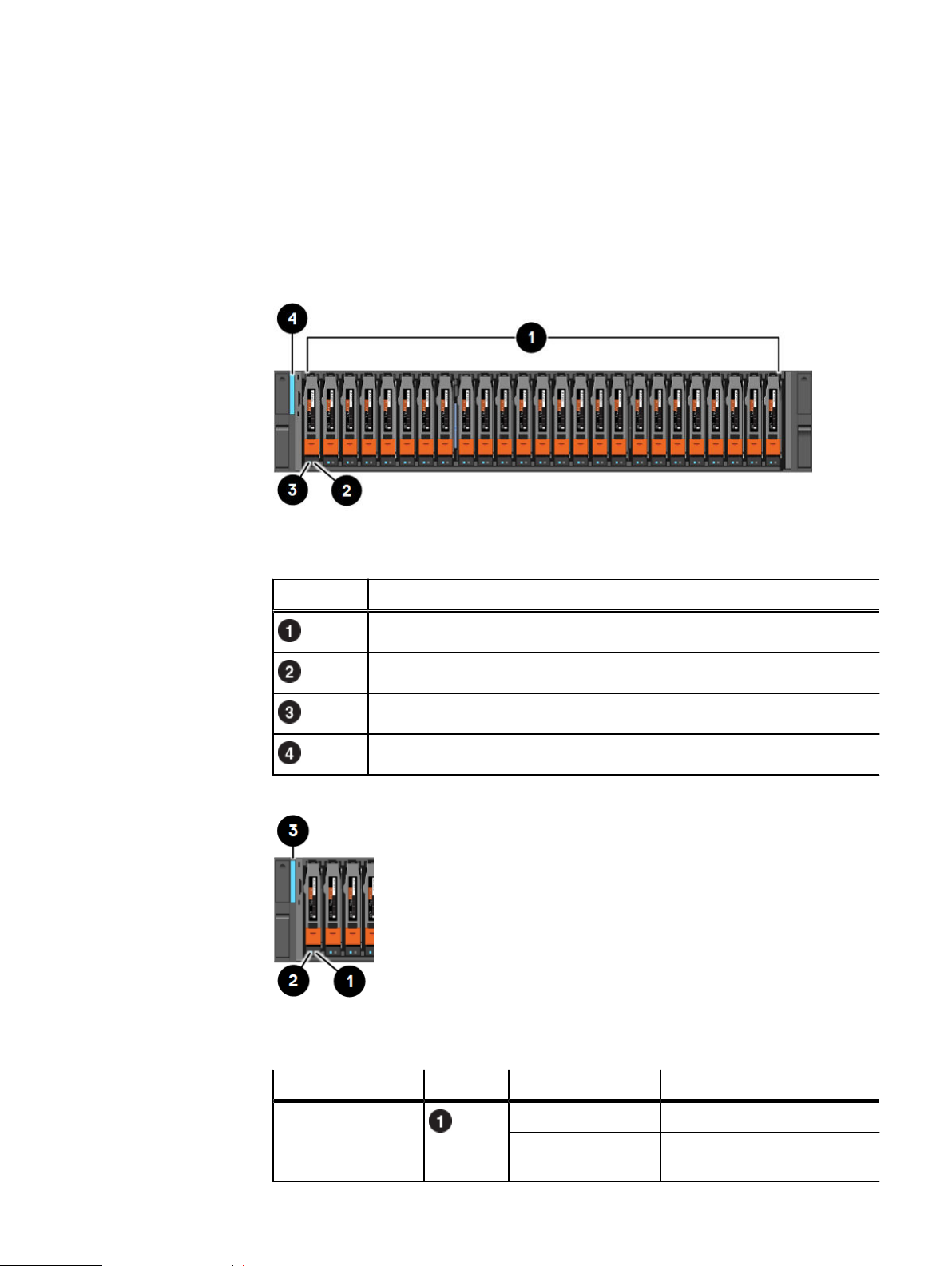
DPE front view
On the front, the DPE contains the following elements:
l
Drives in 2.5 in. carriers
l
Status LEDs
Figure 1 DPE front view
DPE component descriptions
Table 1 DPE component locations
Location Description
SAS or SAS Flash drives
Drive fault LED
Drive ready/activity LED
DPE power on LED
Figure 2 DPE and disk drive LEDs
Table 2 DPE and disk drive LEDs
LED Location State Description
Disk drive fault Amber Fault has occurred.
Off No fault has occurred, normal
operation.
DPE front view 9
DPE component descriptions
Table 2 DPE and disk drive LEDs (continued)
LED Location State Description
Disk drive active Blue Disk drive activity.
DPE fault/power Blue Power is on. No fault has
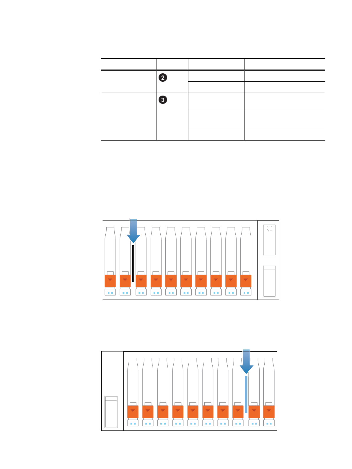
System identification tags
The Product Serial Number Tag (PSNT) and World Wide Name Seed are serialized
labels that allow customer support to track nested hardware material in the field.
Product Serial Number Tag
The PSNT for the 25-slot DPE is a black pull-out tag that is located between the
drives in slots 16 and 17.
Figure 3
PSNT location
Off Disk drive is powered off.
occurred, normal operation.
Amber Power is on. Fault has occurred
within the enclosure.
Off Power is off.
World Wide Name (WWN) Seed Tag
The World Wide Name (WWN) Seed tag is a blue pull-out tag that is located between
the drives in slot 7 and 8.
Figure 4
10 Unity 480/F, Unity 680/F, Unity 880/F Hardware Information Guide
WWN Seed tag location

DPE rear view
5
Note
DPE component descriptions
On the rear of the DPE are two SP assemblies: SP assembly A and SP assembly B.
Each SP assembly contains the following hardware components:
l
One embedded module
l
Two optional I/O modules
l
One power supply module
Figure 5 DPE rear view with hardware component locations
Table 3 DPE hardware component locations
Location Description
Storage processor assembly B
Storage processor assembly A
Power supply module
I/O module, slots 0 and 1
Embedded module
DPE embedded modules and 4-port cards
About embedded modules
Each SP assembly contains one embedded module that can hold one 4-port card for
connectivity.
Both SP assemblies must have the same type of embedded modules in the same slots.
The embedded module contains the following components:
l
One 4-port card
l
One non-maskable interrupt (NMI) button
l
Two mini-SAS HD back-end ports
l
Two RJ-45 LAN connectors
DPE rear view 11

Note
5
6
7
8
DPE component descriptions
n
System management port ( )
n
Service port ( )
l
One USB 3.0 port
l
One mini-USB port (unused)
l
One DB9 serial port (service access)
The following figure shows the location of these components on the embedded
module in SP assembly A. The location of the components in SP assembly B is
mirrored.
Figure 6 Embedded module rear view with component locations
Table 4 Embedded module component locations
Location Description
4-port card
Mini serial port (unused)
Mini-SAS HD back-end ports
DB9 serial port (unused)
RJ-45 LAN connector - service port
RJ 45 LAN connector - system management port
Non-maskable interrupt (NMI) button
USB 3.0 port
About 4-port cards
The 4-port card is an optional component located within the embedded module. There
are two supported 4-port cards: the 25GbE 4-port card and the 10GbE BaseT 4-port
card.
The 25GbE 4-port card supports 1GbE SFP to RJ45, 10GbE or 25GbE SFP28, 25GbE
passive TwinAx, and 10GbE active or passive TwinAx. Depending on the installed SFP
or TwinAx cable, the following speeds are supported: 1GbE, 10GbE, and 25GbE. The
ports may be configured individually with TwinAx or any of the supported SFPs.
12 Unity 480/F, Unity 680/F, Unity 880/F Hardware Information Guide

DPE component descriptions
The 10GbE BaseT 4-port card serves Ethernet traffic and iSCSI block protocol. The
following speeds are supported: 1GbE and 10 GbE.
Embedded module and 4-port card LED status
Figure 7 Embedded module LEDs
Table 5 Embedded module LEDs
LED Location State Description
Embedded module power Amber Embedded module has faulted
Off No fault has occurred, normal
operation.
Ethernet port link Green Link established.
Off No link established.
Ethernet port activity Amber Port activity.
Off No port activity.
SAS port/activity Link Blue SAS port link is up.
Off No link established.
Port link Green Link up with high speed.
Amber Link up with degraded speed.
Off Link down.
Storage processor assembly
fault
Amber Fault has occurred.
Blue Storage processor assembly
in Degraded Mode.
Amber or blue
blinking
Blue and
amber
alternating
(green for 3
seconds)
System is booting.
System not initialized. A
management IP address has
not been assigned.
Blue and
amber
alternating at
one second
intervals
DPE embedded modules and 4-port cards 13
Storage processor assembly
in Service Mode.

DPE component descriptions
Table 5 Embedded module LEDs (continued)
LED Location State Description
Off No fault has occurred, normal
operation.
Storage processor assembly
power
Unsafe to remove White Do not remove the embedded
Nonmaskable interrupt (NMI) button
The nonmaskable interrupt (NMI) button is a recessed button located on the
embedded module, which is used to reset the system password or force a system
reboot.
Use a bent paper clip or pen to press the recessed button. Press the button for
approximately 2 seconds to reset the password. The SP assembly fault LED blinks blue
when the password has been successfully reset.
Press the button for 10 or more seconds to force a system reboot.
Figure 8
Location of the NMI button on the embedded module
Green Storage processor assembly
is on (main power).
Green blinking Storage processor assembly
is initializing a serial over LAN
session (Standby Mode).
Off Storage processor assembly
is off.
module. Improper removal
could cause data loss.
Off Safe to remove the embedded
module when the embedded
module has been properly
prepared.
DPE I/O module types
I/O module installation priority
There are two I/O module slots per SP assembly: slot 0 and slot 1. Slot 0 has a 16 lane
PCIe channel, and slot 1 has an 8 lane PCIe channel.
Populate new I/O modules in the following order to take advantage of the increased
speed on slot 0. If two I/O modules are ordered, use the same installation priority for
both I/O modules.
14 Unity 480/F, Unity 680/F, Unity 880/F Hardware Information Guide
DPE component descriptions
1. 4-port 25GbE Optical I/O module
2. 4-port 16Gb Fibre Channel I/O module
3. 4-port 10GbE BaseT I/O module
4. 4-port 12Gb SAS backend I/O module
When adding new I/O modules, always install I/O modules in pairs: one module in SP
assembly A and one module in SP assembly B. Both SP assemblies must have the
same type of I/O modules in the same slots.
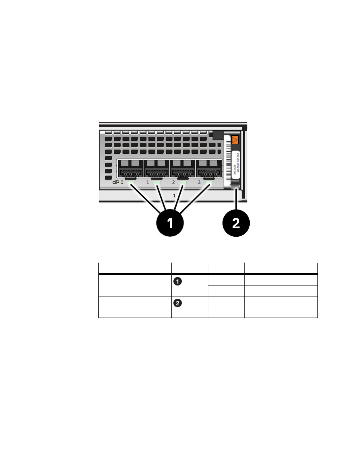
I/O module LED status
Figure 9 DPE I/O module LEDs
Table 6 DPE I/O module LEDs
LED Location State Description
Port link Green or blue Link up
Off Link down
Power fault Green Power
Amber Power fault
4-port 25GbE Optical I/O module
The 4-port 25GbE Optical I/O module is an Ethernet I/O module that is used to serve
Ethernet network traffic and iSCSI block protocol to hosts for the platform. The I/O
module uses an optical 10G or 25G capable SFP+ connection to a host or switch port.
4-port 16Gb Fibre Channel I/O module
The 4-port 16Gb Fibre Channel I/O module comes with four optical ports, one power
and fault LED, and a combination link and activity LED for each optical port. This I/O
module can interface at speeds of 4, 8, and 16 Gb/s FC for host or initiator layered
connections.
4-port 10GbE BaseT I/O module
The 4-port 10GbE BaseT I/O module can interface at speeds of 1 Gb/s and 10 Gb/s
and supports both IP(file) and iSCSI (Block) on the same SP assembly. Ports can be
configured as both IP and iSCSI simultaneously. The I/O module comes with four 10Gb/s RJ-45 ports, one power/fault LED, activity LED, and link LED for each port.
DPE I/O module types 15

Note
Note
NOTICE
DPE component descriptions
4-port 12Gb SAS backend I/O module
Where supported, the 4-port 12Gb SAS backend I/O module comes with four x4 lane
mini-SAS high density (HD) ports, one power and fault LED, and a combination link
and activity LED for each port. Install thisI/O module into the SP assembly to provide
additional SAS buses. Labeled 12Gb SAS v1.
The optional back-end 12-Gb/s SAS module is only supported on Unity 480F, Unity
680F, and Unity 880F systems.
The 4-port 12Gb SAS backend I/O module can also be configured to support x8 lane
cabling for the 80-drive DAE by combining ports 0 and 1 as back-end 2, or ports 2 and
3 to create back-end 4. The I/O module can also be configured to support both x4 lane
and x8 lane back-ends simultaneously.
If the 4-port 12Gb SAS backend I/O module is to be configured for x8 lane cabling, the
x8 lane cable must be inserted into the I/O module before persisting it. If the x8 lane
cables are not inserted into the I/O module first, all four ports default to x4 lane ports.
DPE power supply
The power supply used in your system must meet the system power requirements and
must be the same type of power supply to be used in both nodes. Do not mix power
supply types.
Figure 10 DPE power supply LEDs
Table 7 DPE power supply LEDs
LED Location State Description
AC power (input) Green AC power is on.
Off AC power is off. Verify source
power
DC power (output) Green DC power is on.
Off DC power is off. Verify source
power.
Fault Solid amber Power supply or backup fault.
Check cable connection.
16 Unity 480/F, Unity 680/F, Unity 880/F Hardware Information Guide

Note
DPE component descriptions
Table 7 DPE power supply LEDs (continued)
LED Location State Description
Blinking
amber
Off No fault.
BIOS, POST, and OS starting
up or system overheating.
Storage processor assembly internal components
Included within the SP assembly are the following components:
l
Dual inline memory modules (DIMM)
l
M.2 SSDs
l
Internal battery backup module
l
Fan module
Dual inline memory modules
Twenty-four, 288-pin DIMM sockets support up to 12 DDR4 DIMMs, capable of up to
96 GB, 192 GB, or 384 GB of memory, depending on the model.
Internal battery backup module
The SP assembly includes a Lithium-ion (Li-ion) internal battery that powers the
associated SP assembly during a power event.
M.2 SSD
Each SP assembly has two slots for M.2 SSD on a M.2 SSD adaptor located between
DIMM slots 5/17 and 6/18. One M.2 SSD is used for general system operations, while
the other M.2 SSD is used for vaulting.
Fan module
Six redundant fan modules connect to the motherboard within the SP assembly to
provide continuous airflow through the front drives and through the rear of the SP
assembly to keep the components at optimal operating temperatures.
The SP assembly performs a protective thermal shutdown if two cooling modules fault
within the same SP assembly.
Storage processor assembly internal components 17

DPE component descriptions
18 Unity 480/F, Unity 680/F, Unity 880/F Hardware Information Guide

CHAPTER 2
Technical specifications
l
Technical specifications..................................................................................... 20
l
Dimensions and weight....................................................................................... 21
l
Power requirements........................................................................................... 21
l
Operating environment requirements.................................................................22
Technical specifications 19

Technical specifications
Technical specifications
Storage processor assembly specifications
Parameter (per SP
assembly)
Unity 480/480F Unity 680/680F Unity 880/880F
CPU Two, 8-core 1.8 GHz
Intel Skylake
processors
Memory 96 GB (12 x 8 GB) 192 GB (12 x 16 GB) 384 GB (12 x 32 GB)
Embedded SAS ports Two, 4-lane 12 GB
SAS
Optional SAS ports Four, 4-lane or two,
8-lane 12 Gb/s SAS
I/O module
Two, 12-core 2.1 GHz
Intel Skylake
processors
Two, 4-lane 12 GB
SAS
Four, 4-lane or two,
8-lane 12 Gb/s SAS
I/O module
Two, 16-core 2.1 GHz
Intel Skylake
processors
Two, 4-lane 12 GB
SAS
Four, 4-lane or two,
8-lane 12 Gb/s SAS
I/O module
DAE and drive specifications
Supported DAEs:
l
2U, 25-drive disk-array enclosure
l
3U, 15-drive disk-array enclosure
l
3U, 80-drive disk-array enclosure
Table 8
Drive and DAE support
Parameter Unity 480/480F Unity 680/680F Unity 880/880F
Maximum drives 750 1000 1500
Minimum drives 4 4 4
Maximum DAEs 48 60 60
Maximum 25-drive
DAE
Maximum 15-drive
DAE
Maximum 80-drive
DAE
29 (750) 39 (1000) 59 (1500)
48 (745) 60 (925) 60 (925)
9 (745) 12 (985) 18 (1465)
Drive counts listed in parentheses next to the maximum amount of DAEs represent the
maximum achievable drive count when using the maximum of each DAE, plus the 25
drives on the DPE.
Embedded module specifications
Supported optional 4-port cards:
l
10GbE BaseT 4-port card
l
25GbE 4-port card
The 4-port card can also be left unpopulated.
I/O module specifications
Supported I/O modules:
20 Unity 480/F, Unity 680/F, Unity 880/F Hardware Information Guide

Note
Technical specifications
l
4-port 16Gb Fibre Channel I/O module
l
4-port 25GbE Optical I/O module
l
4-port 10GbE BaseT I/O module
l
4-port 12Gb SAS backend I/O module
Power supply unit specifications
You can use high line power, such as in a rack, or low line power, such as from a wall
power outlet, to supply power to the DPE. All Unity models support both high line and
low line power. A step-up transformer, not included, is required to use high line power
with Unity 880/880F systems.
Table 9 Power specifications per Unity model
Model High line Low line
Unity 480/480F 1800 W 1450 W
Unity 680/680F 1800 W 1450 W
Unity 880/880F 1800 W 1800 W (Step-up
transformer required)
Dimensions and weight
Table 10
Dimension Value
Weight (unpopulated) 25.9 kg (54.11 lbs)
Vertical size 2 NEMA units
Height 8.72 cm (3.43 in.)
Width 44.72 cm (17.61 in.)
Depth 79.55 cm (31.32 in.)
The weight does not include mounting rails. Allow approximately 2.3-4.5 kg (5-10 lb)
for a rail set.
2U, 25-drive DPE, dimensions and weight
Power requirements
Power consumption values are based on enclosures with all power supplies, drives,
embedded modules and I/O modules populated.
To estimate power consumption values for your specific environment, go to https://
powercalculator.emc.com/.
Dimensions and weight 21

Technical specifications
Table 11 DPE power requirements, per model
Specification Unity 480/480F Unity 680/680F Unity880/880F
AC line voltage 100 to 240 VAC
± 10%, single phase,
47 to 63 Hz
AC line current
(operating maximum)
Power consumption
(operating maximum)
Power factor 0.95 minimum at full
Heat dissipation
(operating maximum)
In-rush current 45 Apk cold per line
Startup surge current 120 Apk hot per line
10.6 A max at 100
VAC; 5.3 A max at
200VAC
1060 VA (1050W)
max at 100 VAC; 1060
VA (1050 W) max at
200 VAC
load, @ 100/ 200 VAC
3.78 x 10⁶ J/hr,
(3,581 Btu/hr) max at
100 VAC; 3.78 x 10
J/hr, (3,581 Btu/hr)
max 200VAC
cord, at any line
voltage
cord, at any line
voltage
100 to 240 VAC
± 10%, single phase,
47 to 63 Hz
11.72 A max at 100
VAC; 5.86 A max at
200VAC
1172 VA (1161 W) max
at 100 VAC; 1172 VA
(1161 W) max at 200
VAC
0.95 minimum at full
load, @ 100/ 200 VAC
4.18 x 10⁶ J/hr,
(3,960 Btu/hr) max
6
at 100 VAC; 4.18 x 10
J/hr, (3,960 Btu/hr)
max 200VAC
45 Apk cold per line
cord, at any line
voltage
120 Apk hot per line
cord, at any line
voltage
100 to 240 VAC
± 10%, single phase,
47 to 63 Hz
14.41 A max at 100
VAC; 7.2 A max at
200VAC
1440.77 VA (1411.96)
max at 100 VAC;
1440.77 VA (1411.96
W) max at 200 VAC
0.95 minimum at full
load, @ 100/ 200 VAC
5.08 x 10⁶ J/hr,
(4,818 Btu/hr) max at
6
100 VAC; 5.08 x 10
J/hr, (4,818 Btu/hr)
max 200VAC
45 Apk cold per line
cord, at any line
voltage
120 Apk hot per line
cord, at any line
voltage
6
AC protection 20 A fuse on each
power supply, single
line
AC inlet type (high
line power)
AC inlet type (low line
power)
Ride-through sharing 10 ms min 10 ms min 10 ms min
Current sharing ± 5 percent of full
IEC320-C14 appliance
coupler, per power
zone
IEC320-C20
appliance coupler, per
power zone
load, between power
supplies
Operating environment requirements
Temperature gradient and altitude requirements
Systems and components must not experience changes in temperature and humidity
that are likely to cause condensation to form on or in that system or component. Do
not exceed the temperature gradient of 20°C/hr (36°F/hr), or the altitude
requirement of 3050 m (10,0000 ft).
20 A fuse on each
power supply, single
line
IEC320-C14 appliance
coupler, per power
zone
IEC320-C20
appliance coupler, per
power zone
± 5 percent of full
load, between power
supplies
20 A fuse on each
power supply, single
line
IEC320-C14 appliance
coupler, per power
zone
IEC320-C20
appliance coupler, per
power zone
± 5 percent of full
load, between power
supplies
22 Unity 480/F, Unity 680/F, Unity 880/F Hardware Information Guide

Technical specifications
Recommended range of operation
The recommended range of operation is the limit under which equipment operates the
most reliably while still achieving reasonably energy-efficient data center operation.
The recommended range of operation is 18°C–27°C (64.4°F to 80.6°F) at 5.5°C
(41.9°F) dew point to 60% relative humidity and 15°C (59°F) dew point.
Continuous allowable range of operation
Data center economization techniques such as free cooling can be employed to
improve overall data center efficiency. These techniques can cause equipment inlet
conditions to fall outside the recommended range, but still within the continuously
allowable range. Equipment can be operated without any hourly limitations in this
range.
The continuous allowable range of operation is 10°C–35°C (50°F–95°F) at 20% to
80% relative humidity with 21°C (69.8°F) maximum dew point (maximum wet bulb
temperature). De-rate the maximum allowable dry bulb temperature by 1°C per 300 m
above 950 m (1°F per 547 ft above 3117 ft).
Expanded allowable range of operation
During certain times of the day or year, equipment inlet conditions can fall outside the
continuously allowable range but still within the expanded improbable range.
Equipment operation is limited to ≤ 10% of annual operating hours in this range.
The expanded allowable range of operation is 5°C–10°C and 35°C–40°C (with no
direct sunlight on the equipment) at -12°C dew point and 8% to 85% relative humidity
with 24°C dew point (maximum wet bulb temperature). Outside the continuously
allowable range (10°C–35°C), the system can operate down to 5°C or up to 40°C for
a maximum of 10% of its annual operating hours. For temperatures 35 °C–40°C
(95°F–104°F), de-rate the maximum allowable dry bulb temperature by 1°C per 175 m
above 950 m (1°F per 319 ft above 3117 ft).
DPE airflow
Exceptions to the expanded allowable range of operation
During certain times of the day or year, equipment inlet conditions can fall outside the
continuously allowable range but still within the expanded exceptional range.
Equipment operation is limited to ≤ 1% of annual operating hours in this range.
Exceptions to the expanded allowable range of operation are 5°C–10°C and 35°C–
40°C (with no direct sunlight on the equipment) at -12°C dew point and 8% to 85%
relative humidity with 24°C dew point (maximum wet bulb temperature). Outside the
continuously allowable range (10°C–35°C), the system can operate down to 5°C or
up to 45°C for a maximum of 1% of its annual operating hours. For temperatures
between 35°C and 45°C (95°F–104°F), de-rate the maximum allowable dry bulb
temperature by 1°C per 125 m above 950 m (1°F per 228 ft above 3117 ft).
The DPE uses an adaptive cooling algorithm that increases or decreases fan speed as
the unit senses changes to the external ambient temperature. Exhaust increases with
ambient temperature and fan speed, and is roughly linear within recommended
operating parameters. Note that the information in the table below is typical, and was
measured without cabinet front/rear doors that would potentially reduce front-toback air flow.
DPE airflow 23

NOTICE
Technical specifications
Table 12 DPE airflow
Max Airflow CFM Min Airflow CFM Max Power
106 CFM 40 CFM 850 W
Environmental recovery
If the system exceeds the maximum ambient temperature by approximately 10°C
(18°F), the SP assemblies in the system begin an orderly shutdown that saves cached
data, and then shut themselves down. Link control cards (LCCs) in each DAE in the
system power down disks but remain powered on.
If the system detects that the temperature has dropped to an acceptable level, it
restores power to the DPEs and the LCCs restore power to their disks.
Shipping and storage requirements
Usage (Watts)
Shock and Vibration
Systems and components must not experience changes in temperature and humidity
that are likely to cause condensation to form on or in that system or component. Do
not exceed the shipping and storage temperature gradient of 45°F/hr (25°C/hr).
Table 13 Shipping and storage requirements
Requirement Description
Ambient temperature -40° F to 149°F (-40°C to 65°C)
Temperature gradient 45°F/hr (25°C/hr)
Relative humidity 10% to 90% noncondensing
Elevation -50 to 35,000 ft (-16 to 10,600 m)
Storage time (unpowered) Recommendation Do not exceed 6 consecutive months of
unpowered storage.
Products have been tested to withstand the shock and random vibration levels. The
levels apply to all three axes and should be measured with an accelerometer on the
equipment enclosures within the cabinet and shall not exceed:
Platform condition
Response measurement level
Non operational shock 10 G’s, 7 ms duration
Operational shock 3 G’s, 11 ms duration
Non operational random vibration 0.40 Grms, 5–500 Hz, 30 minutes
Operational random vibration 0.21 Grms, 5–500 Hz, 10 minutes
24 Unity 480/F, Unity 680/F, Unity 880/F Hardware Information Guide

Note
Technical specifications
Systems that are mounted on an approved package have completed transportation
testing to withstand the following shock and vibrations in the vertical direction only
and shall not exceed:
Packaged system condition Response measurement level
Transportation shock 10 G’s, 12ms duration
Transportation random vibration
Fire suppressant disclaimer
Fire prevention equipment in the computer room should always be installed as an
added safety measure. A fire suppression system is the responsibility of the customer.
When selecting appropriate fire suppression equipment and agents for the data
center, choose carefully. An insurance underwriter, local fire marshal, and local
building inspector are all parties that you should consult during the selection of a fire
suppression system that provides the correct level of coverage and protection.
Equipment is designed and manufactured to internal and external standards that
require certain environments for reliable operation. We do not make compatibility
claims of any kind nor do we provide recommendations on fire suppression systems. It
is not recommended to position storage equipment directly in the path of high
pressure gas discharge streams or loud fire sirens so as to minimize the forces and
vibration adverse to system integrity.
The previous information is provided on an “as is” basis and provides no
representations, warranties, guarantees or obligations on the part of our company.
This information does not modify the scope of any warranty set forth in the terms and
conditions of the basic purchasing agreement between the customer and the
manufacturer.
l
1.15 Grms
l
1 hour Frequency range 1–200 Hz
Air quality requirements
The products are designed to be consistent with the requirements of the American
Society of Heating, Refrigeration and Air Conditioning Engineers (ASHRAE)
Environmental Standard Handbook and the most current revision of Thermal
Guidelines for Data Processing Environments, Second Edition, ASHRAE 2009b.
Cabinets are best suited for Class 1 datacom environments, which consist of tightly
controlled environmental parameters, including temperature, dew point, relative
humidity and air quality. These facilities house mission-critical equipment and are
typically fault-tolerant, including the air conditioners.
The data center should maintain a cleanliness level as identified in ISO 14664-1, class 8
for particulate dust and pollution control. The air entering the data center should be
filtered with a MERV 11 filter or better. The air within the data center should be
continuously filtered with a MERV 8 or better filtration system. In addition, efforts
should be maintained to prevent conductive particles, such as zinc whiskers, from
entering the facility.
The allowable relative humidity level is 20 to 80% non condensing, however, the
recommended operating environment range is 40 to 55%. For data centers with
gaseous contamination, such as high sulfur content, lower temperatures and humidity
Fire suppressant disclaimer 25

Technical specifications
are recommended to minimize the risk of hardware corrosion and degradation. In
general, the humidity fluctuations within the data center should be minimized. It is also
recommended that the data center be positively pressured and have air curtains on
entry ways to prevent outside air contaminants and humidity from entering the
facility.
For facilities below 40% relative humidity, it is recommended to use grounding straps
when contacting the equipment to avoid the risk of Electrostatic discharge (ESD),
which can harm electronic equipment.
As part of an ongoing monitoring process for the corrosiveness of the environment, it
is recommended to place copper and silver coupons (per ISA 71.04-1985, Section 6.1
Reactivity), in airstreams representative of those in the data center. The monthly
reactivity rate of the coupons should be less than 300 Angstroms. When monitored
reactivity rate is exceeded, the coupon should be analyzed for material species and a
corrective mitigation process put in place.
Storage time (unpowered) recommendation: do not exceed 6 consecutive months of
unpowered storage.
26 Unity 480/F, Unity 680/F, Unity 880/F Hardware Information Guide
 Loading...