


Dell EMC™ PowerMax™ Family
Best Practices Guide
for AC Power Connections
PowerMax 2000 and PowerMax 8000
with PowerMaxOS
REVISION 2.0

Copyright © 2018 Dell Inc. or its subsidiaries. All rights reserved.
Published May 2018
Dell believes the information in this publication is accurate as of its publication date. The information is subject to change without notice.
THE INFORMATION IN THIS PUBLICATION IS PROVIDED “AS-IS.“ DELL MAKES NO REPRESENTATIONS OR WARRANTIES OF ANY KIND
WITH RESPECT TO THE INFORMATION IN THIS PUBLICATION, AND SPECIFICALLY DISCLAIMS IMPLIED WARRANTIES OF
MERCHANTABILITY OR FITNESS FOR A PARTICULAR PURPOSE. USE, COPYING, AND DISTRIBUTION OF ANY DELL SOFTWARE DESCRIBED
IN THIS PUBLICATION REQUIRES AN APPLICABLE SOFTWARE LICENSE.
Dell, EMC, and other trademarks are trademarks of Dell Inc. or its subsidiaries. Other trademarks may be the property of their respective owners.
Published in the USA.
Dell EMC
Hopkinton, Massachusetts 01748-9103
1-508-435-1000 In North America 1-866-464-7381
www.DellEMC.com
2 Best Practices Guide for AC Power Connections PowerMax 2000 and PowerMax 8000 with PowerMaxOS

5
7
Preface 9
Revision history...........................................................................................12
Best Practices Guide for AC Power Connections 13
Best practices overview for AC power connections.................................... 14
Selecting the proper AC power connection procedure................................ 15
Procedure A: Working with the customer's electrician onsite..................... 16
Procedure A, Task 1: Customer's electrician...................................17
Procedure A, Task 2: Dell EMC Customer Engineer .......................18
Procedure A, Task 3: Customer's electrician.................................. 21
Procedure B: Verify and connect................................................................22
Procedure C: Obtain customer verification.................................................23
PDU labels.................................................................................................. 23
PDU label part number...................................................................23
Applying PDU labels.......................................................................25
Ground the cabinet.....................................................................................25
AC power specifications............................................................................. 27
Figures
Tables
Chapter 1
CONTENTS
Best Practices Guide for AC Power Connections PowerMax 2000 and PowerMax 8000 with PowerMaxOS 3

CONTENTS
4 Best Practices Guide for AC Power Connections PowerMax 2000 and PowerMax 8000 with PowerMaxOS

Two independent customer-supplied PDUs.................................................................14
Circuit breakers ON — AC power within specification................................................ 17
Circuit breakers OFF — No AC power........................................................................ 17
Connecting AC power, single-phase, PowerMax 2000................................................18
Connecting AC power, single-phase, PowerMax 8000................................................19
Connecting AC power, three-phase............................................................................ 19
Power zone connections............................................................................................ 20
PDU label , single-phase and three-phase...................................................................25
Location of cabinet ground lugs..................................................................................26
1
2
3
4
5
6
7
8
9
FIGURES
Best Practices Guide for AC Power Connections PowerMax 2000 and PowerMax 8000 with PowerMaxOS 5

FIGURES
6 Best Practices Guide for AC Power Connections PowerMax 2000 and PowerMax 8000 with PowerMaxOS

Typographical conventions used in this content..........................................................10
Revision history...........................................................................................................12
Procedure options for AC power connection ..............................................................15
PDU label part number................................................................................................23
PDU label location, Dell EMC racks.............................................................................23
PDU label location, third-party racks.......................................................................... 24
Input power requirements - Single-phase, North American, International, Australian
................................................................................................................................... 27
Input power requirements - Three-phase, North American, International, Australian
................................................................................................................................... 28
1
2
3
4
5
6
7
8
TABLES
Best Practices Guide for AC Power Connections PowerMax 2000 and PowerMax 8000 with PowerMaxOS 7

TABLES
8 Best Practices Guide for AC Power Connections PowerMax 2000 and PowerMax 8000 with PowerMaxOS

Preface
As part of an effort to improve its product lines, Dell EMC periodically releases
revisions of its software and hardware. Therefore, some functions described in this
document might not be supported by all versions of the software or hardware
currently in use. The product release notes provide the most up-to-date information
on product features.
Contact your Dell EMC representative if a product does not function properly or does
not function as described in this document.
Note
This document was accurate at publication time. New versions of this document might
be released on Dell EMC Online Support (https://support.emc.com). Check to ensure
that you are using the latest version of this document.
Purpose
This document describes best practices for connecting AC power to the following
PowerMax arrays:
l
PowerMax 2000
l
PowerMax 8000
Audience
This document is intended for customers who are installing a PowerMax array and
must assure that fault tolerant AC power is supplied to the arrays from independent,
customer-supplied, power distribution units (PDUs).
Related documentation
Dell EMC PowerMax Family Product Guide
Provides information on PowerMax 2000 and 8000 arrays with PowerMaxOS
5978.
Dell EMC PowerMax Family Site Planning Guide
Provides planning information regarding the purchase and installation of a
PowerMax 2000, 8000 with PowerMaxOS.
PowerMaxOS 5978.144.144 Release Notes for Dell EMC PowerMax and All Flash
Describes new features and any limitations.
Dell EMC PowerMax Family Security Configuration Guide
Shows how to securely deploy PowerMax arrays running PowerMaxOS.
Special notice conventions used in this document
Dell EMC uses the following conventions for special notices:
DANGER
Indicates a hazardous situation which, if not avoided, will result in death or
serious injury.
Preface 9

WARNING
Indicates a hazardous situation which, if not avoided, could result in death or
serious injury.
CAUTION
Indicates a hazardous situation which, if not avoided, could result in minor or
moderate injury.
NOTICE
Addresses practices not related to personal injury.
Note
Presents information that is important, but not hazard-related.
Typographical conventions
Dell EMC uses the following type style conventions in this document:
Table 1 Typographical conventions used in this content
Bold
Used for names of interface elements, such as names of windows,
dialog boxes, buttons, fields, tab names, key names, and menu paths
(what the user specifically selects or clicks)
Italic
Used for full titles of publications referenced in text
Monospace
Used for:
l
System code
l
System output, such as an error message or script
l
Pathnames, filenames, prompts, and syntax
l
Commands and options
Monospace italic
Used for variables
Monospace bold
Used for user input
[ ] Square brackets enclose optional values
| Vertical bar indicates alternate selections - the bar means “or”
{ } Braces enclose content that the user must specify, such as x or y or
z
... Ellipses indicate nonessential information omitted from the example
Where to get help
EMC support, product, and licensing information can be obtained as follows:
Product information
Dell EMC technical support, documentation, release notes, software updates, or
information about Dell EMC products can be obtained at https://
support.emc.com (registration required) or https://www.dellemc.com/en-us/
documentation/vmax-all-flash-family.htm.
Preface
10 Best Practices Guide for AC Power Connections PowerMax 2000 and PowerMax 8000 with PowerMaxOS

Technical support
To open a service request through the Dell EMC Online Support (https://
support.emc.com) site, you must have a valid support agreement. Contact your
Dell EMC sales representative for details about obtaining a valid support
agreement or to answer any questions about your account.
Your comments
Your suggestions help us improve the accuracy, organization, and overall quality of the
documentation. Send your comments and feedback to:
VMAXContentFeedback@emc.com
Preface
11

Revision history
Table 2 Revision history
Revision Description and/or change Date
released
2.0 Updated Procedure A, Task 2 for PowerMax 2000. May, 2018
1.0 First release of the
Dell EMC Best Practices Guide for AC Power
Connections for PowerMax 2000, 8000 with PowerMaxOS
.
May, 2018
Preface
12 Best Practices Guide for AC Power Connections PowerMax 2000 and PowerMax 8000 with PowerMaxOS

CHAPTER 1
Best Practices Guide for AC Power
Connections
l
Best practices overview for AC power connections............................................14
l
Selecting the proper AC power connection procedure........................................15
l
Procedure A: Working with the customer's electrician onsite.............................16
l
Procedure B: Verify and connect....................................................................... 22
l
Procedure C: Obtain customer verification........................................................ 23
l
PDU labels..........................................................................................................23
l
Ground the cabinet............................................................................................ 25
l
AC power specifications.....................................................................................27
Best Practices Guide for AC Power Connections
13
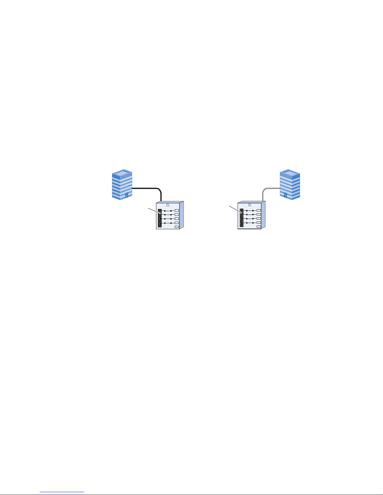
Best practices overview for AC power connections
To assure fault tolerant power, external AC power must be supplied from independent,
customer-supplied, power distribution units (PDUs) as shown in Figure 1 on page 14.
For systems operating from three phase AC power, two independent and isolated AC
power sources are recommended for the two individual power zones in each rack of
the system. This provides for the highest level of redundancy and system availability.
If independent AC power is not available, there is a higher risk of data unavailability
should a power failure occur, including individual phase loss occurring in both power
zones.
Before connecting external AC power to storage bays, verify that the bays have been
placed in their final position as explained in the installation guide.
Figure 1 Two independent customer-supplied PDUs
Customer’s
PDU 1
Customer’s
PDU 2
Circuit
breakers
on (|)
Circuit
breakers
on (|)
Circuit breakers - Numbers
27
28
29
30
Circuit breakers - Numbers
...
8
9
10
11
...
Power feed 1
Power feed 2
Best Practices Guide for AC Power Connections
14 Best Practices Guide for AC Power Connections PowerMax 2000 and PowerMax 8000 with PowerMaxOS

Selecting the proper AC power connection procedure
Note
The Dell EMC Customer Engineer must select the proper AC power connection
procedure.
Table 3 on page 15 summarizes the three possible scenarios to connect customer
AC power to the storage array. Select the procedure that matches the customer's
situation.
Table 3 Procedure options for AC power connection
Situation on site Procedure
The customer’s electrician is available at the installation site. Procedure A: Working with the customer's electrician onsite
on page 16. This procedure assures fault tolerant power in
the storage array.
The customer’s electrician is NOT available at the installation
site, but you have access to customer-supplied, labeled,
power cables (beneath a raised floor or overhead).
Procedure B: Verify and connect on page 22
The customer’s electrician is NOT available at the installation
site, customer-supplied PDU source cables are already
plugged into the PDU , and you have no access to the
customer-supplied power cables.
Procedure C: Obtain customer verification on page 23
Best Practices Guide for AC Power Connections
Selecting the proper AC power connection procedure 15

Procedure A: Working with the customer's electrician onsite
Use this procedure if the customer’s electrician is available at the installation site.
This procedure requires three basic tasks that alternate between the customer's
electrician, the Dell EMC CE and back to the customer's electrician.
l
Task 1: Customer's electrician
l
Task 2: Dell EMC Customer Engineer (CE)
l
Task 3: Customer's electrician
Best Practices Guide for AC Power Connections
16 Best Practices Guide for AC Power Connections PowerMax 2000 and PowerMax 8000 with PowerMaxOS

Procedure A, Task 1: Customer's electrician
NOTICE
This task is performed by the customer's electrician.
Procedure
1. Verify that the customer-supplied AC source voltage output on each customersupplied PDU is within the AC power specification shown in AC power
specifications on page 27. Measure the voltage output of each power cable as
shown in Figure 2 on page 17.
2. Turn OFF all the relevant circuit breakers in customer-supplied PDU 1 and
customer-supplied PDU 2.
3. Verify that the customer-supplied power cables connected to PDU 1 and PDU 2
have no power as shown in Figure 3 on page 17.
Figure 2 Circuit breakers ON — AC power within specification
Customer’s
PDU 1
Customer’s
PDU 2
Circuit
breakers
on (|)
Circuit
breakers
on (|)
Circuit breakers - Numbers
27
28
29
30
Circuit breakers - Numbers
...
8
9
10
11
...
Labels on
customer
power lines
Power feed 1
Power feed 2
PDU 1
CB 28
PDU 2
CB 9
Volt
m
ete
r
TYPE PM89
CLASS 25 01
0
100
240
300
V
Volt
m
ete
r
TYPE PM89
CLASS 25 01
0
100
240
300
V
Figure 3 Circuit breakers OFF — No AC power
Customer’s
PDU 1
Customer’s
PDU 2
Circuit
breaker
off (0)
Circuit
breaker
off (0)
Circuit breakers - Numbers
27
28
29
30
Circuit breakers - Numbers
...
8
9
10
11
...
PDU 2
CB 9
PDU 1
CB 28
Labels on
customer
power lines
Voltmeter
TYPE PM89
CLASS 25 01
0
100
240
300
V
Voltmeter
TYPE PM89
CLASS 25 01
0
100
240
300
V
Best Practices Guide for AC Power Connections
Procedure A, Task 1: Customer's electrician 17

Procedure A, Task 2: Dell EMC Customer Engineer
Before you begin
Before connecting power to the system, make sure that the power for both zone A
and zone B are turned OFF. This task is performed by the Dell EMC Customer
Engineer.
Procedure
1. Confirm that the customer-supplied power cables are labeled and that each
label contains the relevant customer-supplied PDU and circuit breaker numbers.
If power cables are not equipped with labels, alert the customer.
2. Compare the numbers on the customer-supplied power cables for each storage
bay to verify that power zone A and power zone B are powered by a different
customer-supplied PDU.
3. Do one of the following to connect power zone A and power zone B in each bay.
l
For single-phase power: Connect customer-supplied PDU power cables to
the storage bay by connecting to the bay's AC input cables for power zone A
and power zone B as shown below.
Figure 4 Connecting AC power, single-phase, PowerMax 2000
Customer’s PDU 1
Zone B
AC input
cable B
Mating connector or
customer-supplied cable
Customer’s PDU 2
Zone A
AC input
cable A
Mating connector or
customer-supplied cable
Dell EMC-supplied power cable
and connector from the PDU
Cable connectors are shown
as they exit the bottom rear
of the bay.
Rear view
System bay
Dell EMC-supplied power cable
and connector from the PDU
P1 P3 P4 P1 P3 P4
System #1: P1, P3
System #2: P4, P6
P3 and P6 used
depending on
conguration
P6 P6
Best Practices Guide for AC Power Connections
18 Best Practices Guide for AC Power Connections PowerMax 2000 and PowerMax 8000 with PowerMaxOS
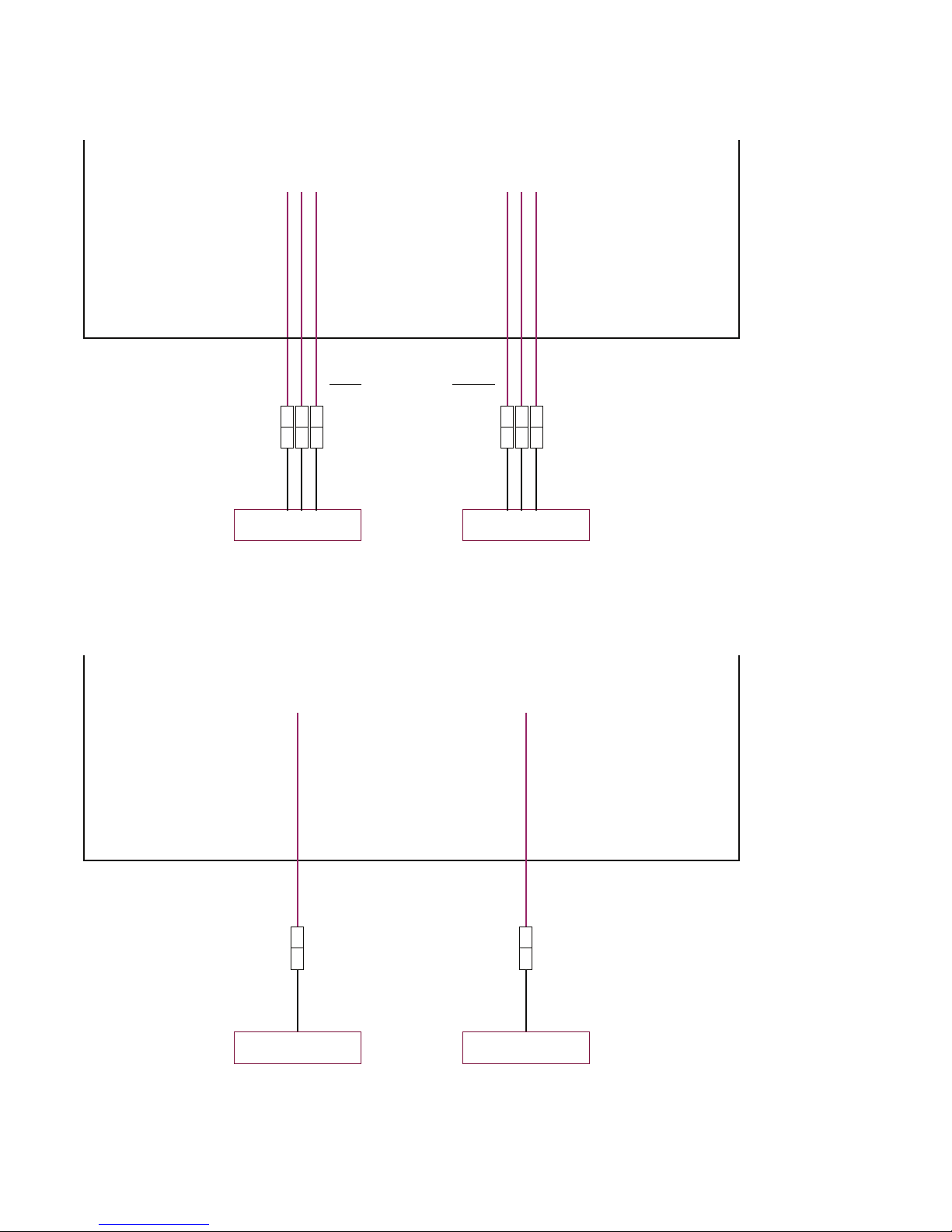
Figure 5 Connecting AC power, single-phase, PowerMax 8000
Customer’s PDU 1
Zone B
AC input
cable B
Mating connector or
customer-supplied cable
Customer’s PDU 2
Zone A
AC input
cable A
Mating connector or
customer-supplied cable
Dell EMC-supplied power cable
and connector from the PDU
Cable connectors are shown
as they exit the bottom rear
of the bay.
Rear view
System bay
Dell EMC-supplied power cable
and connector from the PDU
P1 P3 P5 P1 P3 P5
P3 and P5 used
depending on
conguration
l
For three-phase power: Connect customer-supplied PDU power cables to
the storage bay by connecting to the bay's AC input cables for power zone A
and power zone B as shown below.
Figure 6
Connecting AC power, three-phase
Customer’s PDU 1
Zone B
AC input
cable B
Mating connector or
customer-supplied cable
Customer’s PDU 2
Zone A
AC input
cable A
Mating connector or
customer-supplied cable
Dell EMC-supplied power cable
and connector from the PDU
Rear view
System bay
Dell EMC-supplied power cable
and connector from the PDU
Cable connectors are shown
as they exit the bottom rear
of the bay.
Best Practices Guide for AC Power Connections
Procedure A, Task 2: Dell EMC Customer Engineer 19

NOTICE
Do not connect storage bay power zone A and power zone B to the same
customer-supplied PDU. The customer will lose power redundancy and risk Data
Unavailability (DU) if the PDU fails or is turned off during a maintenance
procedure.
Figure 7 Power zone connections
:tnatropm
I
launam noitcurtsni ot refeR
Zone B Zone A
(Rear View)
SYSTEM
Customer’s Power
Source 1
Circuit
Breakers
(CBs)
Zone B Zone A
(Rear View)
SYSTEM
Customer’s Power
Source 1
Circuit
Breakers
(CBs)
Customer’s Power
Source 2
Circuit
Breakers
(CBs)
:tnatropm
I
launam noitcurtsni ot refeR
Zone B Zone A
(Rear View)
SYSTEM
Customer’s Power
Source 1
Circuit
Breakers
(CBs)
Zone B Zone A
(Rear View)
SYSTEM
Customer’s Power
Source 1
Circuit
Breakers
(CBs)
Customer’s Power
Source 2
Circuit
Breakers
(CBs)
046-001-749_01
Best Practices Guide for AC Power Connections
20 Best Practices Guide for AC Power Connections PowerMax 2000 and PowerMax 8000 with PowerMaxOS

Procedure A, Task 3: Customer's electrician
Note
This task is performed by the customer's electrician.
Procedure
1. Working with the Dell EMC Customer Engineer, turn ON all the relevant circuit
breakers in customer-supplied PDU 2.
Verify that only power supply and/or SPS LEDs in power zone A are ON or
flashing green in every bay in the array.
CAUTION
The bay is incorrectly wired if all (power zone A and B) power supply
and/or SPS LEDs in a bay are ON or flashing green. Check that the AC
power to both storage bay power zones is not supplied by a single PDU
(customer-supplied PDU 2). The wiring must be corrected before moving
on to the next step.
2. Turn OFF the relevant circuit breakers in customer-supplied PDU 2.
Verify that the power supply and/or SPS LEDs that turned green in the
previous step changed from green to OFF and/or flashing yellow. The yellow
SPS lights flash for a maximum of 5 minutes.
Note
Power supplies connected to an SPS continue to have green lights ON while the
SPS yellow light continues to flash indicating the SPS is providing on-battery
power.
3. Repeat step 1 and step 2 for power zone B and customer-supplied PDU 1.
4. Turn ON all the relevant circuit breakers in customer-supplied PDU 1 and
customer-supplied PDU 2.
5. Label the PDUs as described in Applying PDU labels on page 25.
Best Practices Guide for AC Power Connections
Procedure A, Task 3: Customer's electrician 21

Procedure B: Verify and connect
Perform this procedure if the two conditions listed below are true:
l
You have access to customer-supplied, labeled, power cables (beneath raised floor
or overhead).
l
The customer's electrician is not available at the installation site.
This procedure requires the Dell EMC Customer Engineer to verify that the
customer's electrician has complied with power specifications. Once verified, the Dell
EMC Customer Engineer makes the required power connections overhead or under
the floor.
Procedure
1. Have the customer verify that their electrician has complied with power
specifications for voltage levels and redundancy. If the customer cannot verify
this, provide them with a copy of Procedure A. Inform the customer that their
array may prematurely shut down in the event of a site power issue.
2. Access the labeled, power cables (beneath raised floor or overhead) to verify
that the customer-supplied power cables are properly labeled as shown in
Figure 3 on page 17 and described in Procedure A, Task 2.
3. Compare the numbers on the customer-supplied power cables for each storage
bay to verify that power zone A and power zone B are powered by a different
customer-supplied PDU.
4. Connect the customer-supplied power cables to the storage bay power zones
as described in Procedure A, Task 2.
5. Record the customer-supplied PDU information as described in Procedure A,
Task 2.
6. Label the PDUs as described in Applying PDU labels on page 25.
Best Practices Guide for AC Power Connections
22 Best Practices Guide for AC Power Connections PowerMax 2000 and PowerMax 8000 with PowerMaxOS

Procedure C: Obtain customer verification
Perform this procedure if the three conditions listed below are true:
l
The customer-supplied PDU source cables are already plugged into the storage
bay PDU.
l
You have no access to the area below the raised floor.
l
The customer's electrician is not available at the installation site.
Procedure
1. Have the customer verify that their electrician has complied with power
specifications for voltage levels and redundancy. If the customer cannot verify
this, provide them with a copy of Procedure A. Inform the customer that their
array may prematurely shut down in the event of a site power issue.
2. Record the customer-supplied PDU information (AC source voltage) as
described in step 1 of Procedure A, Task 1: Customer's electrician on page 17
and label the PDUs as described in Applying PDU labels on page 25.
PDU labels
Before applying labels to the sidewalls of the cabinet, one of the following procedures
must have been completed:
l
Procedure A: Working with the customer's electrician onsite on page 16
l
Procedure B: Verify and connect on page 22
l
Procedure C: Obtain customer verification on page 23
If necessary, see Selecting the proper AC power connection procedure on page 15 to
select the correct procedure.
PDU label part number
Table 4
PDU label part number
Part Number Description
046-001-750 LABEL: CUSTOMER 1P 3P PDU INFO WRITEABLE
Table 5 PDU label location, Dell EMC racks
Product Location
PowerMax 2000 HERC OPEN ME FIRST KIT
PN 106-887-306
PowerMax 8000 OPEN ME FIRST FIELD INSTALL KIT
PN 106-887-026
Best Practices Guide for AC Power Connections
Procedure C: Obtain customer verification 23

Table 6 PDU label location, third-party racks
Product Location
PowerMax 2000 HERC ENG 1 PBRICK 3RD PTY INSTALL KIT
PN 106-887-303
PowerMax 8000 ENGINE 1 3RD PTY PBRICK ZEUS
PN 106-887-268
Best Practices Guide for AC Power Connections
24 Best Practices Guide for AC Power Connections PowerMax 2000 and PowerMax 8000 with PowerMaxOS

Applying PDU labels
Procedure
1. For each bay, locate and complete each PDU label.
Note
For three-phase power, enter data only in the P1 column.
2. Place each label on the rear cabinet sidewall for side A and B.
Figure 8 PDU label , single-phase and three-phase
3. For third-party racks, do one of the following:
l
For three-phase power: Using plastic ties, attach the PDU connection tag to
the main AC power cable connected to zone A and B. Place the label close to
the plug but on the side of the rack where it will not interfere with any rails.
l
For single-phase power: Using plastic ties, attach the PDU connection tag to
the P1 AC power cable connected to zone A and B. Place the label close to
the plug but on the side of the rack where it will not interfere with any rails.
Ground the cabinet
Equipment correctly installed within the cabinet is grounded through the AC power
cables and connectors. In general, supplemental grounding is not required.
If your site requires external grounding (for example, to a common grounding network
beneath the site floor), you can use the grounding lugs provided on each of the
cabinet’s bottom supports.
Best Practices Guide for AC Power Connections
Applying PDU labels 25

Figure 9 Location of cabinet ground lugs
CL4827
046-003-350
Best Practices Guide for AC Power Connections
26 Best Practices Guide for AC Power Connections PowerMax 2000 and PowerMax 8000 with PowerMaxOS

AC power specifications
Table 7 Input power requirements - Single-phase, North American, International, Australian
Specification North American 3-wire
connection
(2 L & 1 G)
a
International and
Australian 3-wire
connection
(1 L & 1 N & 1 G)
a
Input nominal voltage 200–240 VAC ± 10% L- L
nom
220–240 VAC ± 10% L- N
nom
Frequency 50–60 Hz 50–60 Hz
Circuit breakers 30 A 32 A
Power zones Two Two
Minimum power requirements
at customer site
l
PowerMax 2000: Up to two 30 A or 32 A single-phase
drops per zone.
l
PowerMax 8000: Up to three 30 A or 32 A single-phase
drops per zone.
l
Two power zones require 6 drops, each drop rated for 30
A or 32 A. (Maximum PowerMax 8000 configuration.)
l
PDU A and PDU B require three separate single-phase 30
A or 32 A drops for each PDU.
a.
L = line or phase, N = neutral, G = ground
Best Practices Guide for AC Power Connections
AC power specifications 27

Table 8 Input power requirements - Three-phase, North American, International, Australian
Specification North American 4-wire
connection
(3 L & 1 G)
a
International 5-wire
connection
(3 L & 1 N & 1 G)
a
Input voltage
b
200–240 VAC ± 10% L- L
nom
220–240 VAC ± 10% L- N
nom
Frequency 50–60 Hz 50–60 Hz
Circuit breakers 50 A 32 A
Power zones Two Two
Minimum power requirements
at customer site
l
Two 50 A, three-phase
drops per bay.
l
PDU A and PDU B require
one separate three-phase
Delta 50 A drops for
each.
Two 32 A, three-phase drops
per bay.
a.
L = line or phase, N = neutral, G = ground
b.
An imbalance of AC input currents may exist on the three-phase power source feeding the
array, depending on the configuration. The customer's electrician must be alerted to this
possible condition to balance the phase-by-phase loading conditions within the customer's
data center.
Best Practices Guide for AC Power Connections
28 Best Practices Guide for AC Power Connections PowerMax 2000 and PowerMax 8000 with PowerMaxOS
 Loading...