

Page 1

Latitude 5490
Owner’s Manual
Regulatory Model: P72G
Regulatory Type: P72G002
Page 2

Notes, cautions, and warnings
NOTE: A NOTE indicates important information that helps you make better use of your product.
CAUTION: A CAUTION indicates either potential damage to hardware or loss of data and tells you how to avoid the problem.
WARNING: A WARNING indicates a potential for property damage, personal injury, or death.
Copyright © 2018 Dell Inc. or its subsidiaries. All rights reserved. Dell, EMC, and other trademarks are trademarks of Dell Inc. or its subsidiaries. Other
trademarks may be trademarks of their respective owners.
2018 - 01
Rev. A00
Page 3

Contents
1 Working on your computer............................................................................................................................. 7
Safety precautions............................................................................................................................................................. 7
Standby power..............................................................................................................................................................7
Bonding .........................................................................................................................................................................7
Electrostatic discharge — ESD protection...............................................................................................................7
ESD eld service kit ....................................................................................................................................................8
Transporting sensitive components...........................................................................................................................9
Before working inside your computer..............................................................................................................................9
After working inside your computer.................................................................................................................................9
2 Removing and installing components............................................................................................................10
Recommended tools........................................................................................................................................................ 10
Screw size list.................................................................................................................................................................... 11
Subscriber Identity Module(SIM) board.........................................................................................................................11
Removing the Subscriber Identication Module card............................................................................................. 11
Installing the Subscriber Identication Module card...............................................................................................12
Base cover.........................................................................................................................................................................12
Removing the base cover..........................................................................................................................................12
Installing the base cover............................................................................................................................................ 14
Battery............................................................................................................................................................................... 14
Removing the battery................................................................................................................................................ 14
Installing the battery...................................................................................................................................................14
Solid State Drive — optional ..........................................................................................................................................15
Removing the SSD card.............................................................................................................................................15
Installing the SSD card...............................................................................................................................................16
Removing the SSD frame..........................................................................................................................................16
Installing the SSD frame.............................................................................................................................................17
Hard drive.......................................................................................................................................................................... 17
Removing hard drive...................................................................................................................................................17
Installing hard drive ....................................................................................................................................................18
Coin cell battery................................................................................................................................................................18
Removing the coin cell battery................................................................................................................................. 18
Installing coin cell battery...........................................................................................................................................19
WLAN card........................................................................................................................................................................19
Removing WLAN card................................................................................................................................................19
Installing WLAN card................................................................................................................................................. 20
WWAN card – optional................................................................................................................................................... 20
Removing the WWAN card.......................................................................................................................................20
Installing the WWAN card..........................................................................................................................................21
Memory modules.............................................................................................................................................................. 21
Removing the memory module.................................................................................................................................21
Installing the memory module...................................................................................................................................22
Keyboard........................................................................................................................................................................... 22
Contents
3
Page 4

Removing keyboard lattice........................................................................................................................................22
Installing keyboard lattice.......................................................................................................................................... 23
Removing the keyboard............................................................................................................................................ 23
Installing the keyboard...............................................................................................................................................26
Heat sink .......................................................................................................................................................................... 26
Removing the heat sink ............................................................................................................................................26
Installing the heat sink .............................................................................................................................................. 27
System fan........................................................................................................................................................................27
Removing the system fan......................................................................................................................................... 27
Installing the system fan............................................................................................................................................28
Power connector port..................................................................................................................................................... 28
Removing the power connector port...................................................................................................................... 28
Installing power connector port............................................................................................................................... 29
Chassis frame...................................................................................................................................................................29
Removing the chassis frame.................................................................................................................................... 29
Installing the chassis frame........................................................................................................................................31
LED board......................................................................................................................................................................... 32
Removing LED board.................................................................................................................................................32
Installing LED board................................................................................................................................................... 32
SmartCard module...........................................................................................................................................................33
Removing smart card reader board......................................................................................................................... 33
Installing smart card reader board............................................................................................................................34
Speaker............................................................................................................................................................................. 35
Removing the speaker...............................................................................................................................................35
Installing the speaker.................................................................................................................................................36
System board....................................................................................................................................................................36
Removing system board............................................................................................................................................36
Installing system board.............................................................................................................................................. 39
Display hinge cover..........................................................................................................................................................40
Removing display hinge cover .................................................................................................................................40
Installing display hinge cover ....................................................................................................................................41
Display assembly............................................................................................................................................................... 41
Removing display assembly....................................................................................................................................... 41
Installing display assembly.........................................................................................................................................45
Display bezel..................................................................................................................................................................... 46
Removing display bezel ............................................................................................................................................ 46
Installing display bezel ...............................................................................................................................................46
Display panel..................................................................................................................................................................... 47
Removing display panel ............................................................................................................................................ 47
Installing display panel .............................................................................................................................................. 48
Display (eDP) cable..........................................................................................................................................................49
Removing display cable ............................................................................................................................................49
Installing display cable .............................................................................................................................................. 49
Camera..............................................................................................................................................................................50
Removing camera......................................................................................................................................................50
Installing camera......................................................................................................................................................... 51
Display hinges....................................................................................................................................................................51
Contents
4
Page 5

Removing display hinge .............................................................................................................................................51
Installing display hinge .............................................................................................................................................. 52
Display back cover assembly..........................................................................................................................................52
Removing the display back cover assembly ..........................................................................................................52
Installing the display back cover assembly .............................................................................................................53
Palm rest...........................................................................................................................................................................54
Removing palm rest...................................................................................................................................................54
Installing palm rest..................................................................................................................................................... 55
3 Technical specications...............................................................................................................................56
Processor .........................................................................................................................................................................56
Memory ............................................................................................................................................................................ 57
Storage specication.......................................................................................................................................................57
Audio specications......................................................................................................................................................... 57
Video specication...........................................................................................................................................................58
integrated....................................................................................................................................................................58
Discrete.......................................................................................................................................................................58
Camera option .................................................................................................................................................................58
Ports and Connectors .................................................................................................................................................... 59
Contactless smart card...................................................................................................................................................59
Display specication........................................................................................................................................................ 59
Keyboard specication for Latitude 5490.....................................................................................................................60
Keyboard hot key denitions for Latitude 5490.....................................................................................................60
Touch pad specications..................................................................................................................................................61
Battery specications......................................................................................................................................................62
AC Adapter specications...............................................................................................................................................62
System dimensions.......................................................................................................................................................... 63
Operating Conditions.......................................................................................................................................................63
4 Technology and components....................................................................................................................... 65
Power adapter..................................................................................................................................................................65
DDR4................................................................................................................................................................................. 65
DDR4 Details.............................................................................................................................................................. 65
Memory Errors........................................................................................................................................................... 66
HDMI 1.4............................................................................................................................................................................66
HDMI 1.4 Features......................................................................................................................................................67
Advantages of HDMI................................................................................................................................................. 67
USB features.....................................................................................................................................................................67
USB 3.0/USB 3.1 Gen 1 (SuperSpeed USB)...........................................................................................................67
Speed.......................................................................................................................................................................... 68
Applications.................................................................................................................................................................68
Compatibility...............................................................................................................................................................69
Advantages of Displayport over USB Type-C........................................................................................................ 69
USB Type-C......................................................................................................................................................................69
Alternate Mode...........................................................................................................................................................70
USB Power Delivery...................................................................................................................................................70
Contents
5
Page 6

5 System setup options...................................................................................................................................71
Boot Sequence..................................................................................................................................................................71
Navigation keys................................................................................................................................................................ 72
System Setup overview.................................................................................................................................................. 72
Accessing System Setup.................................................................................................................................................72
General screen options....................................................................................................................................................72
System Conguration screen options............................................................................................................................73
Video screen options........................................................................................................................................................74
Security screen options...................................................................................................................................................74
Secure Boot screen options............................................................................................................................................76
Intel Software Guard Extensions....................................................................................................................................77
Performance screen options...........................................................................................................................................77
Power Management screen options..............................................................................................................................78
POST Behavior screen options...................................................................................................................................... 79
Manageability................................................................................................................................................................... 80
Virtualization support screen options............................................................................................................................80
Wireless screen options................................................................................................................................................... 81
Maintenance screen options........................................................................................................................................... 81
6 Software......................................................................................................................................................83
Operating system congurations................................................................................................................................... 83
Downloading drivers........................................................................................................................................................ 83
Chipset driver............................................................................................................................................................. 83
Serial IO driver............................................................................................................................................................84
Graphics controller driver..........................................................................................................................................84
USB drivers.................................................................................................................................................................84
Network drivers......................................................................................................................................................... 85
Realtek Audio..............................................................................................................................................................85
Serial ATA drivers.......................................................................................................................................................85
Security drivers.......................................................................................................................................................... 86
7 Troubleshooting............................................................................................................................................87
Enhanced Pre-Boot System Assessment — ePSA diagnostics................................................................................ 87
Running the ePSA diagnostics................................................................................................................................. 87
Real Time Clock reset......................................................................................................................................................87
8 Contacting Dell............................................................................................................................................89
6
Contents
Page 7

Working on your computer
Topics:
• Safety precautions
• Before working inside your computer
• After working inside your computer
Safety precautions
The safety precautions chapter details the primary steps to be taken before performing any disassembly instructions.
Observe the following safety precautions before you perform any installation or break/x procedures involving disassembly or reassembly:
• Turn o the system and all attached peripherals.
• Disconnect the system and all attached peripherals from AC power.
• Disconnect all network cables, telephone, and telecommunications lines from the system.
• Use an ESD eld service kit when working inside any notebook to avoid electrostatic discharge (ESD) damage.
• After removing any system component, carefully place the removed component on an anti-static mat.
• Wear shoes with non-conductive rubber soles to reduce the chance of getting electrocuted.
1
Standby power
Dell products with standby power must be unplugged before you open the case. Systems that incorporate standby power are essentially
powered while turned o. The internal power enables the system to be remotely turned on (wake on LAN) and suspended into a sleep
mode and has other advanced power management features.
Unplugging, pressing and holding the power button for 15 seconds should discharge residual power in the system board, notebooks
Bonding
Bonding is a method for connecting two or more grounding conductors to the same electrical potential. This is done through the use of a
eld service electrostatic discharge (ESD) kit. When connecting a bonding wire, ensure that it is connected to bare metal and never to a
painted or non-metal surface. The wrist strap should be secure and in full contact with your skin, and ensure that you remove all jewelry
such as watches, bracelets, or rings prior to bonding yourself and the equipment.
Electrostatic discharge — ESD protection
ESD is a major concern when you handle electronic components, especially sensitive components such as expansion cards, processors,
memory DIMMs, and system boards. Very slight charges can damage circuits in ways that may not be obvious, such as intermittent
problems or a shortened product life span. As the industry pushes for lower power requirements and increased density, ESD protection is an
increasing concern.
Due to the increased density of semiconductors used in recent Dell products, the sensitivity to static damage is now higher than in previous
Dell products. For this reason, some previously approved methods of handling parts are no longer applicable.
Working on your computer 7
Page 8

Two recognized types of ESD damage are catastrophic and intermittent failures.
• Catastrophic – Catastrophic failures represent approximately 20 percent of ESD-related failures. The damage causes an immediate and
complete loss of device functionality. An example of catastrophic failure is a memory DIMM that has received a static shock and
immediately generates a "No POST/No Video" symptom with a beep code emitted for missing or nonfunctional memory.
• Intermittent – Intermittent failures represent approximately 80 percent of ESD-related failures. The high rate of intermittent failures
means that most of the time when damage occurs, it is not immediately recognizable. The DIMM receives a static shock, but the
tracing is merely weakened and does not immediately produce outward symptoms related to the damage. The weakened trace may
take weeks or months to melt, and in the meantime may cause degradation of memory integrity, intermittent memory errors, etc.
The more dicult type of damage to recognize and troubleshoot is the intermittent (also called latent or "walking wounded") failure.
Perform the following steps to prevent ESD damage:
• Use a wired ESD wrist strap that is properly grounded. The use of wireless anti-static straps is no longer allowed; they do not provide
adequate protection. Touching the chassis before handling parts does not ensure adequate ESD protection on parts with increased
sensitivity to ESD damage.
• Handle all static-sensitive components in a static-safe area. If possible, use anti-static oor pads and workbench pads.
• When unpacking a static-sensitive component from its shipping carton, do not remove the component from the anti-static packing
material until you are ready to install the component. Before unwrapping the anti-static packaging, ensure that you discharge static
electricity from your body.
• Before transporting a static-sensitive component, place it in an anti-static container or packaging.
ESD eld service kit
The unmonitored Field Service kit is the most commonly used service kit. Each Field Service kit includes three main components: anti-static
mat, wrist strap, and bonding wire.
Components of an ESD eld service kit
The components of an ESD eld service kit are:
• Anti-Static Mat – The anti-static mat is dissipative and parts can be placed on it during service procedures. When using an anti-static
mat, your wrist strap should be snug and the bonding wire should be connected to the mat and to any bare metal on the system being
worked on. Once deployed properly, service parts can be removed from the ESD bag and placed directly on the mat. ESD-sensitive
items are safe in your hand, on the ESD mat, in the system, or inside a bag.
• Wrist Strap and Bonding Wire – The wrist strap and bonding wire can be either directly connected between your wrist and bare metal
on the hardware if the ESD mat is not required, or connected to the anti-static mat to protect hardware that is temporarily placed on
the mat. The physical connection of the wrist strap and bonding wire between your skin, the ESD mat, and the hardware is known as
bonding. Use only Field Service kits with a wrist strap, mat, and bonding wire. Never use wireless wrist straps. Always be aware that the
internal wires of a wrist strap are prone to damage from normal wear and tear, and must be checked regularly with a wrist strap tester
in order to avoid accidental ESD hardware damage. It is recommended to test the wrist strap and bonding wire at least once per week.
• ESD Wrist Strap Tester – The wires inside of an ESD strap are prone to damage over time. When using an unmonitored kit, it is a best
practice to regularly test the strap prior to each service call, and at a minimum, test once per week. A wrist strap tester is the best
method for doing this test. If you do not have your own wrist strap tester, check with your regional oce to nd out if they have one.
To perform the test, plug the wrist-strap's bonding-wire into the tester while it is strapped to your wrist and push the button to test. A
green LED is lit if the test is successful; a red LED is lit and an alarm sounds if the test fails.
• Insulator Elements – It is critical to keep ESD sensitive devices, such as plastic heat sink casings, away from internal parts that are
insulators and often highly charged.
• Working Environment – Before deploying the ESD Field Service kit, assess the situation at the customer location. For example,
deploying the kit for a server environment is dierent than for a desktop or portable environment. Servers are typically installed in a rack
within a data center; desktops or portables are typically placed on oce desks or cubicles. Always look for a large open at work area
that is free of clutter and large enough to deploy the ESD kit with additional space to accommodate the type of system that is being
repaired. The workspace should also be free of insulators that can cause an ESD event. On the work area, insulators such as Styrofoam
and other plastics should always be moved at least 12 inches or 30 centimeters away from sensitive parts before physically handling any
hardware components
• ESD Packaging – All ESD-sensitive devices must be shipped and received in static-safe packaging. Metal, static-shielded bags are
preferred. However, you should always return the damaged part using the same ESD bag and packaging that the new part arrived in.
The ESD bag should be folded over and taped shut and all the same foam packing material should be used in the original box that the
new part arrived in. ESD-sensitive devices should be removed from packaging only at an ESD-protected work surface, and parts should
Working on your computer
8
Page 9

never be placed on top of the ESD bag because only the inside of the bag is shielded. Always place parts in your hand, on the ESD mat,
in the system, or inside an anti-static bag.
• Transporting Sensitive Components – When transporting ESD sensitive components such as replacement parts or parts to be
returned to Dell, it is critical to place these parts in anti-static bags for safe transport.
ESD protection summary
It is recommended that all eld service technicians use the traditional wired ESD grounding wrist strap and protective anti-static mat at all
times when servicing Dell products. In addition, it is critical that technicians keep sensitive parts separate from all insulator parts while
performing service and that they use anti-static bags for transporting sensitive components.
Transporting sensitive components
When transporting ESD sensitive components such as replacement parts or parts to be returned to Dell, it is critical to place these parts in
anti-static bags for safe transport.
Before working inside your computer
1 Ensure that your work surface is at and clean to prevent the computer cover from being scratched.
2 Turn o your computer.
3 If the computer is connected to a docking device (docked), undock it.
4 Disconnect all network cables from the computer (if available).
CAUTION
computer.
5 Disconnect your computer and all attached devices from their electrical outlets.
6 Open the display.
7 Press and hold the power button for few seconds, to ground the system board.
CAUTION
CAUTION: To avoid electrostatic discharge, ground yourself by using a wrist grounding strap or by periodically touching an
unpainted metal surface at the same time as touching a connector on the back of the computer.
8 Remove any installed ExpressCards or Smart Cards from the appropriate slots.
: If your computer has an RJ45 port, disconnect the network cable by rst unplugging the cable from your
: To guard against electrical shock unplug your computer from the electrical outlet before performing Step # 8.
After working inside your computer
After you complete any replacement procedure, ensure you connect any external devices, cards, and cables before turning on your
computer.
CAUTION
designed for other Dell computers.
1 Replace the battery.
2 Replace the base cover.
3 Connect any external devices, such as a port replicator or media base, and replace any cards, such as an ExpressCard.
4 Connect any telephone or network cables to your computer.
: To avoid damage to the computer, use only the battery designed for this particular Dell computer. Do not use batteries
CAUTION
computer.
5 Connect your computer and all attached devices to their electrical outlets.
6 Turn on your computer.
: To connect a network cable, rst plug the cable into the network device and then plug it into the
Working on your computer
9
Page 10

Removing and installing components
Topics:
• Recommended tools
• Screw size list
• Subscriber Identity Module(SIM) board
• Base cover
• Battery
• Solid State Drive — optional
• Hard drive
• Coin cell battery
• WLAN card
• WWAN card – optional
• Memory modules
• Keyboard
• Heat sink
• System fan
• Power connector port
• Chassis frame
• LED board
• SmartCard module
• Speaker
• System board
• Display hinge cover
• Display assembly
• Display bezel
• Display panel
• Display (eDP) cable
• Camera
• Display hinges
• Display back cover assembly
• Palm rest
2
Recommended tools
The procedures in this document require the following tools:
• Phillips #0 screwdriver
• Phillips #1 screwdriver
• Plastic scribe
: The #0 screw driver is for screws 0-1 and the #1 screw driver is for screws 2-4
NOTE
10 Removing and installing components
Page 11

Screw size list
Table 1. Latitude 5490 screw size list
Component
Base cover 8
Battery 1
Heatsink 4
WLAN 1
SSD card 1
Keyboard 5
Display assembly 4
Display panel 4
Power connector port 2
Palmrest 2
LED board 1
System board 4
Type-C USB bracket 2
Display hinge cover 2
M2x3 (Thin
head)
M2.0x5 M2.0x2.0 M2x6
M2x2.
7
M2.0x2.5 M2.5x3
Display hinge 6
Hard drive 4
Chassis frame 5 8
Touchpad panel(button) 2
Smart card module 2
Subscriber Identity Module(SIM) board
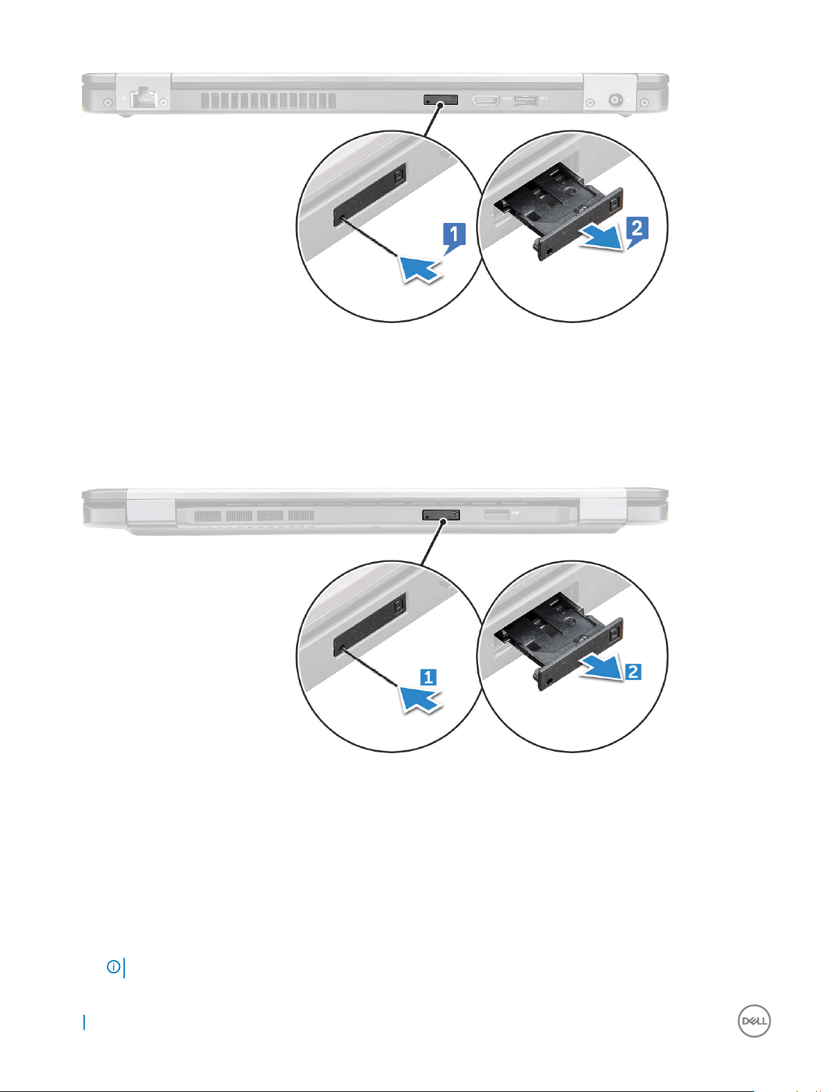
Removing the Subscriber Identication Module card
CAUTION
turned o or the network connections are disabled.
1 Insert a paperclip or a SIM card removal tool into the pinhole on the SIM card tray [1].
2 Pull the SIM card tray to remove it [2].
3 Remove the SIM card from the SIM card tray.
: Removing the SIM card when the computer is on may cause data loss or damage the card. Ensure your computer is
Removing and installing components
11
Page 12
4 Push the SIM card tray into the slot until it clicks into place.
Installing the Subscriber Identication Module card
1 Insert a paperclip or a SIM card removal tool into the pinhole [1].
2 Pull the SIM card tray to remove it [2].
3 Place the SIM card on the SIM card tray.
4 Push the SIM card tray into the slot until it clicks into place.
Base cover
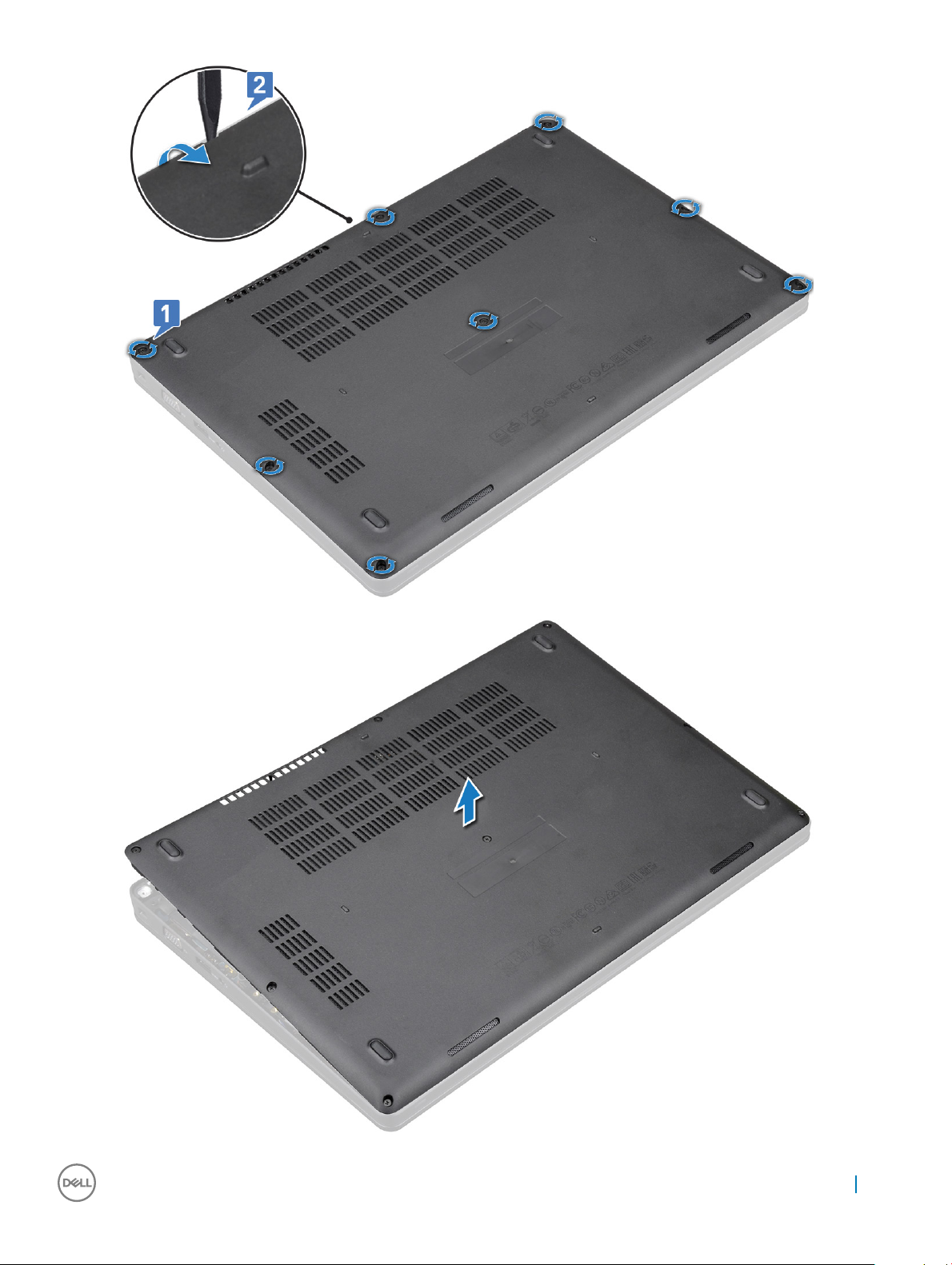
Removing the base cover
1 Follow the procedure in Before working inside your computer.
2 To remove the base cover:
a Loosen the 8 (M2.0x6) captive screws that secure the base cover to the system [1].
b Pry the base cover from therecess at the top edge [2] and lift the base cover away from the system.
: You may need a plastic scribe to pry the base cover from the edges.
NOTE
12 Removing and installing components
Page 13
Removing and installing components 13
Page 14
Installing the base cover
1 Place the base cover to align with the screw holders on the system.
2 Tighten the 8 captive screws to secure the base cover to the system.
3 Follow the procedure in After working inside your computer.
Battery
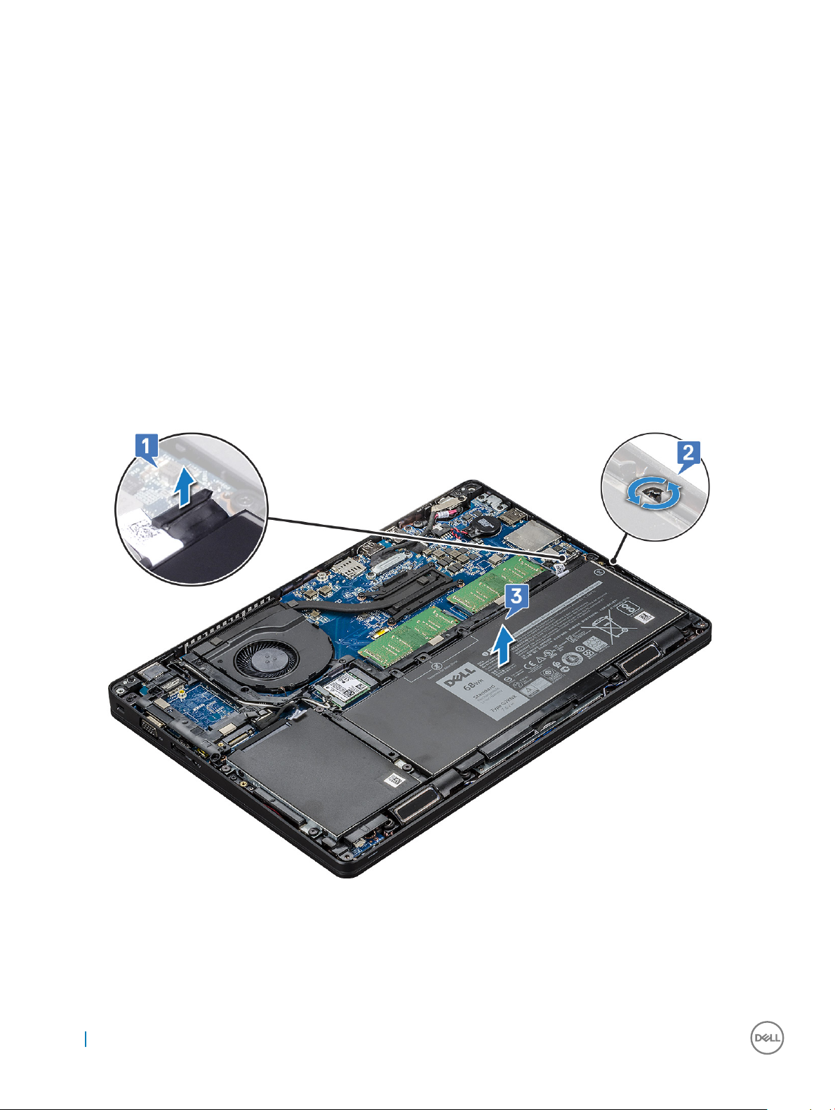
Removing the battery
1 Follow the procedure in Before working inside your computer.
2 Remove the base cover.
3 To remove the battery:
a Disconnect the battery cable from the connector on the system board [1] and unroute the cable from the routing channel.
b Loosen the single (M2x6) captive screw that secures the battery to the system [2].
c Lift the battery away from the system [3].
Installing the battery
1 Insert the battery into the slot on the system.
2 Route the battery cable through the routing channel.
14
Removing and installing components
Page 15
3 Tighten the single (M2x6) captive screw to secure the battery to the system.
4 Connect the battery cable to the connector on the system board.
5 Install the base cover.
6 Follow the procedure in After working inside your computer.
Solid State Drive — optional
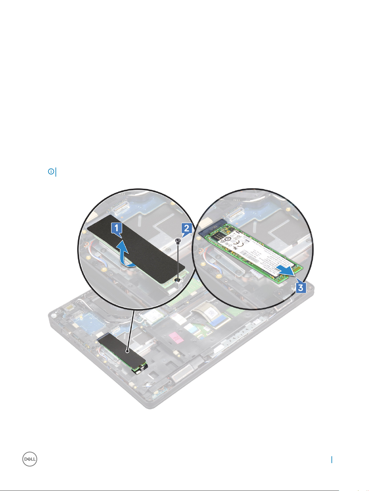
Removing the SSD card
1 Follow the procedure in Before working inside your computer.
2 Remove the :
a base cover
b battery
3 To remove the Solid State Drive (SSD) card:
a Remove the single (M2x3) screw that secures the SSD to the system [1].
b Peel the adhesive mylar shield that secures the SSD card [2].
NOTE: Need to be removed carefully in order to be reused on the replacement SSD.
c Slide and lift the SSD from the system [3].
Removing and installing components 15
Page 16
Installing the SSD card
1 Insert the SSD card into the connector on the system.
2 Replace the single (M2x3) screw that secures the SSD card to the system.
3 Place the Mylar shield over the SSD.
4 Install the :
a battery
b base cover
5 Follow the procedure in After working inside your computer.
Removing the SSD frame
1 Follow the procedure in Before working inside your computer.
2 Remove the:
a base cover
b battery
c SSD card
3 To remove the SSD frame:
a Remove the single (M2x3) screw that secures the SSD frame to the system [1].
b Lift the SSD frame away from the system [2].
16
Removing and installing components
Page 17
Installing the SSD frame
1 Place the SSD frame to the slot in the system.
2 Replace the single (M2x3) screw that secures the SSD frame to the system.
3 Install the:
a SSD card
b battery
c base cover
4 Follow the procedure in After working inside your computer.
Hard drive
Removing hard drive
1 Follow the procedure in Before working inside your computer.
2 Remove the :
a battery
b base cover
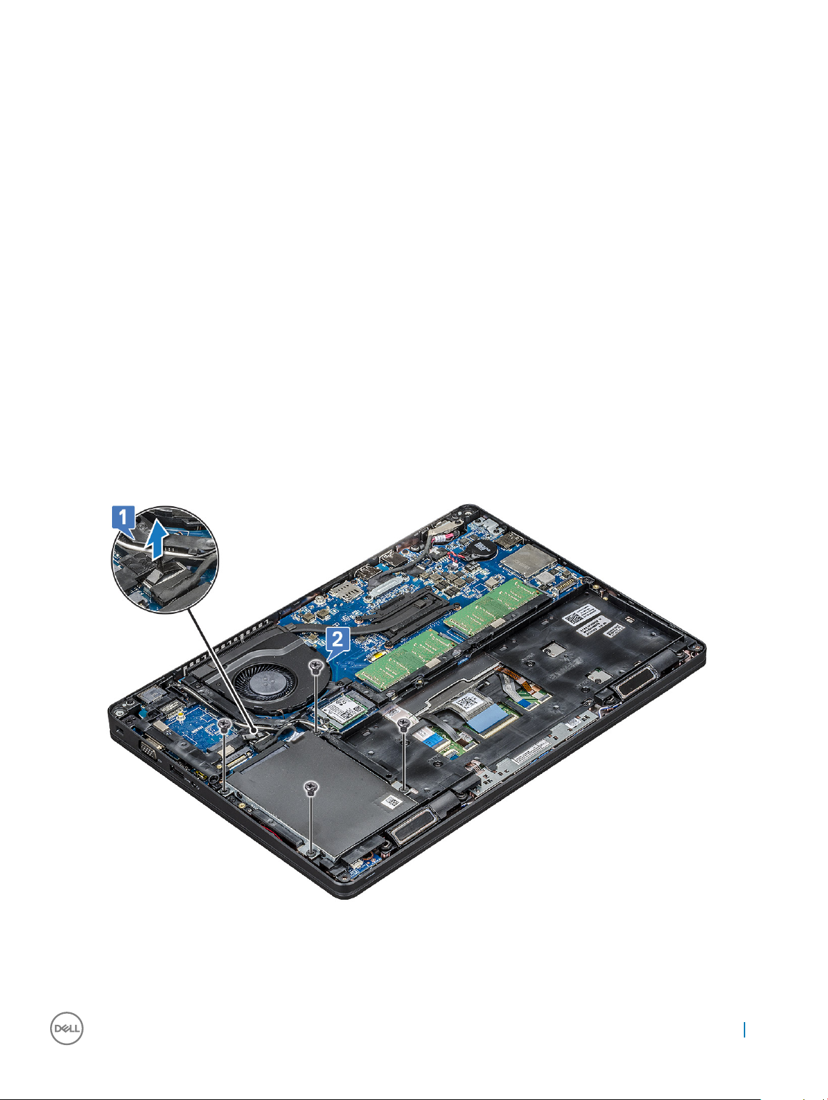
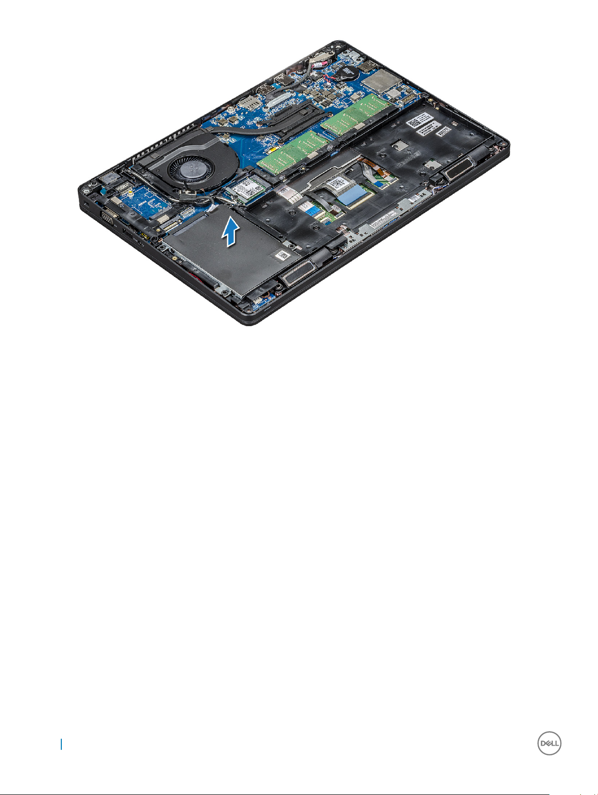
3 To remove the hard drive:
a Disconnect the hard drive cable from the connector on the system board [1].
b Remove the four (M2 x 2.7+2.7) screws that secure the hard drive to the system [2].
c Lift the hard drive away from the system.
Removing and installing components
17
Page 18
Installing hard drive
1 Insert the hard drive into the slot on the system.
2 Replace the four M2 x 2.7+2.7 screws to secure the hard drive to the system.
3 Connect the hard drive cable to the connector on the system board.
4 Install the :
a battery
b base cover
5 Follow the procedures in After working inside your system.
Coin cell battery
Removing the coin cell battery
1 Follow the procedure in Before working inside your computer.
2 Remove the :
a base cover
b battery
3 To remove the coin cell battery:
a Disconnect the coin cell battery cable from the connector on the system board [1].
b Lift the coin cell battery to release from the adhesive and lift it away from the system board [2].
18
Removing and installing components
Page 19

Installing coin cell battery
1 Ax the coin cell battery on the system board.
2 Connect the coin cell battery cable to the connector on the system board.
3 Install the :
a battery
b base cover
4 Follow the procedure in After working inside your computer.
WLAN card
Removing WLAN card
1 Follow the procedure in Before working inside your computer.
2 Remove the :
a base cover
b battery
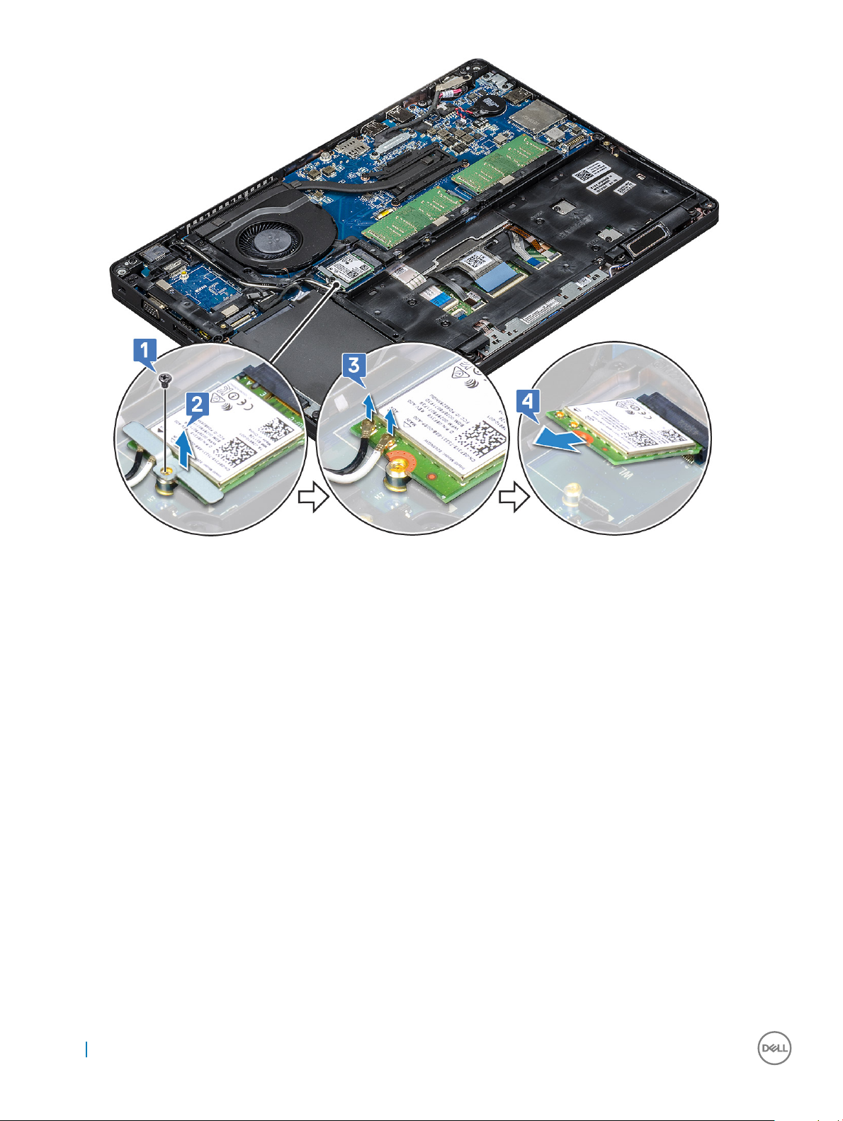
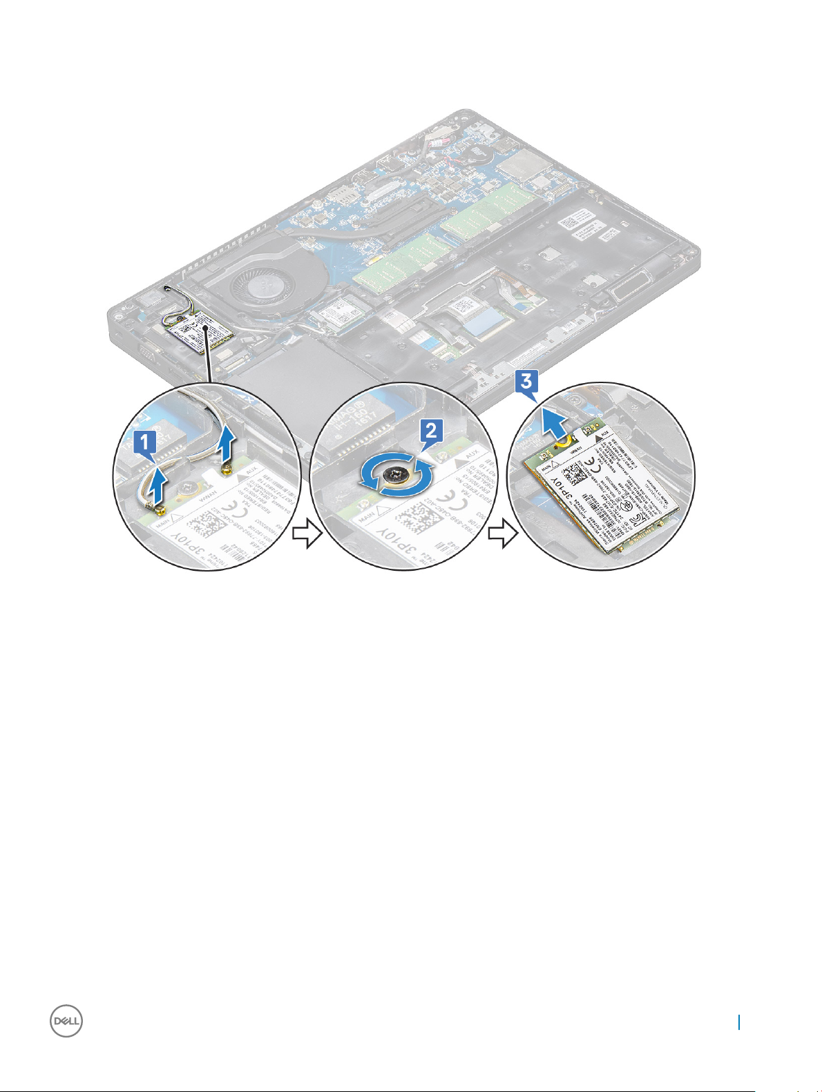
3 To remove the WLAN card:
a Remove the single (M2x3) screw that secures the WLAN card bracket to the system [1].
b Remove the WLAN card bracket that secures the WLAN antenna cables [2].
c Disconnect the WLAN antenna cables from the connectors on the WLAN card [3].
d Lift the WLAN card away from the connector as shown in the gure [4].
Removing and installing components
19
Page 20
Installing WLAN card
1 Insert the WLAN card into the connector on the system board.
2 Connect the WLAN antenna cables to the connectors on the WLAN card.
3 Place the WLAN card bracket to secure the WLAN cables.
4 Replace the single M2x3 screw to secure the WLAN card to the system.
5 Install the :
a battery
b base cover
6 Follow the procedure in After working inside your computer.
WWAN card – optional
This is optional as the system might not ship with WWAN card.
Removing the WWAN card
1 Follow the procedure in Before working inside your computer.
2 Remove the :
a base cover
b battery
3 To remove the WWAN card:
20
Removing and installing components
Page 21
a Disconnect the WWAN antenna cables from the connectors on the WWAN card [1].
b Remove the screw that secures the WWAN card to the system [2]
c Slide and lift the WWAN card from the system [3].
Installing the WWAN card
1 Insert the WWAN card into the slot on the system.
2 Connect the WWAN antenna cables to the connectors on the WWAN card.
3 Replace the screw to secure the WWAN card to the computer.
4 Install the :
a battery
b base cover
5 Follow the procedure in After working inside your computer.
Memory modules
Removing the memory module
1 Follow the procedure in Before working inside your computer.
2 Remove the :
a base cover
b battery
3 To remove the memory module:
Removing and installing components
21
Page 22
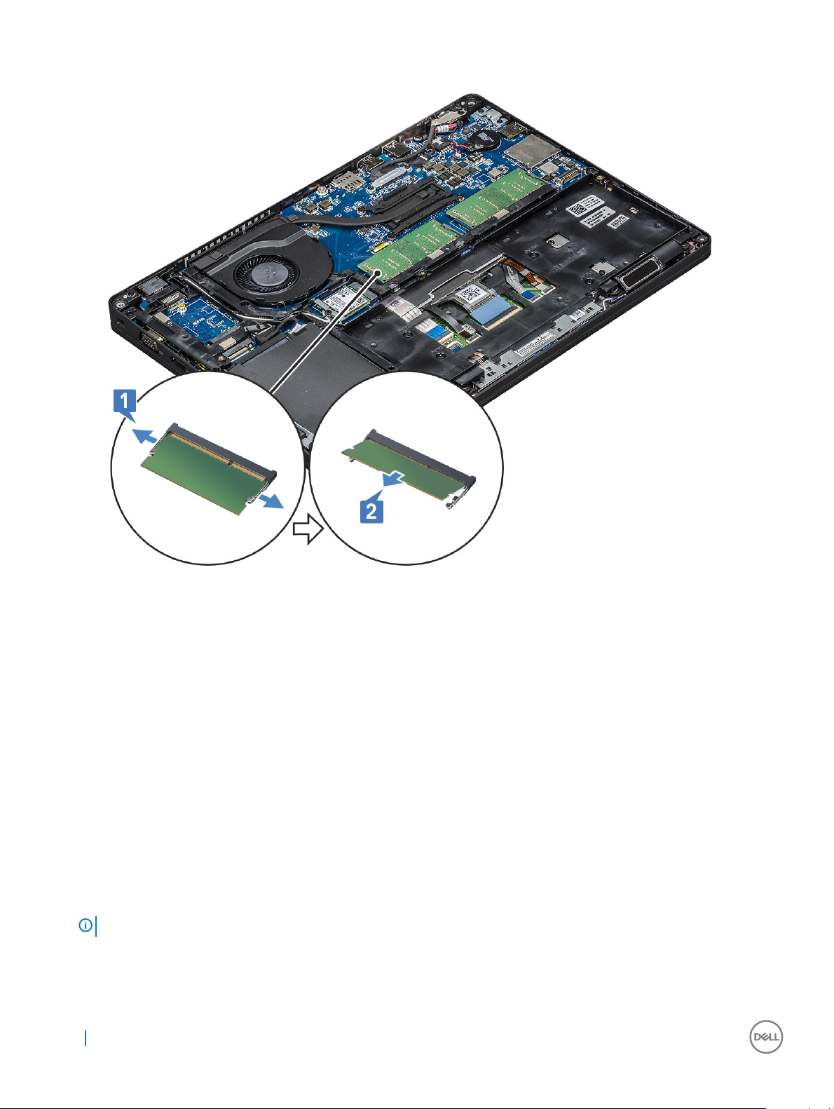
a Pry the clips securing the memory module until the memory module pops-up [1].
b Lift the memory module away from the connector [2].
Installing the memory module
1 Insert the memory module into the memory connector at a 30 degree angle until the contacts are fully seated into the slot. Then,
depress the module until the clips secure the memory module.
2 Install the :
a battery
b base cover
3 Follow the procedure in After working inside your computer.
Keyboard
Removing keyboard lattice
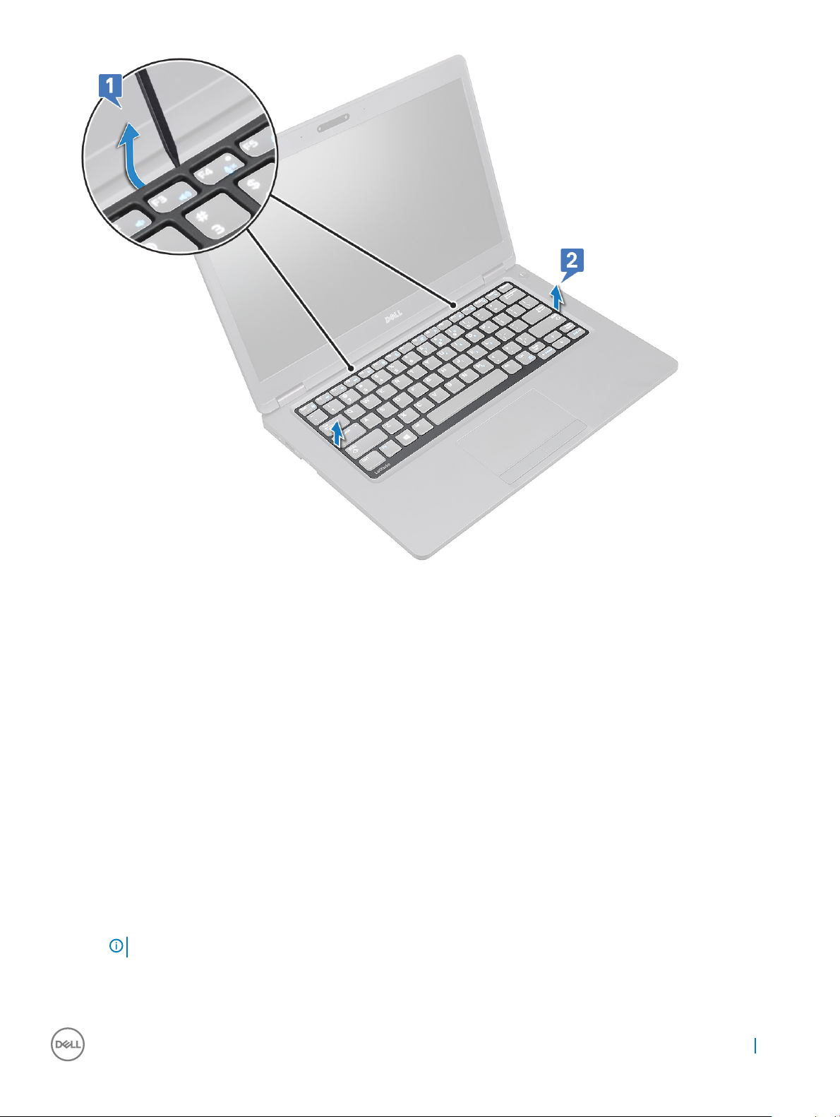
1 Follow the procedure in Before working inside your computer.
2 Pry the keyboard lattice from the edges [1] and lift the lattice away from the system [2].
: Gently pull or lift keyboard lattice in clockwise or anticlockwise direction to avoid breakage.
NOTE
22 Removing and installing components
Page 23
Installing keyboard lattice
1 Place the keyboard lattice on the keyboard and press along the edges as well as in between the rows of keys until the lattice clicks in
place.
2 Follow the procedure in After working inside your computer.
Removing the keyboard
1 Follow the procedure in Before working inside your computer.
2 Remove the:
a base cover
b battery
c keyboard lattice
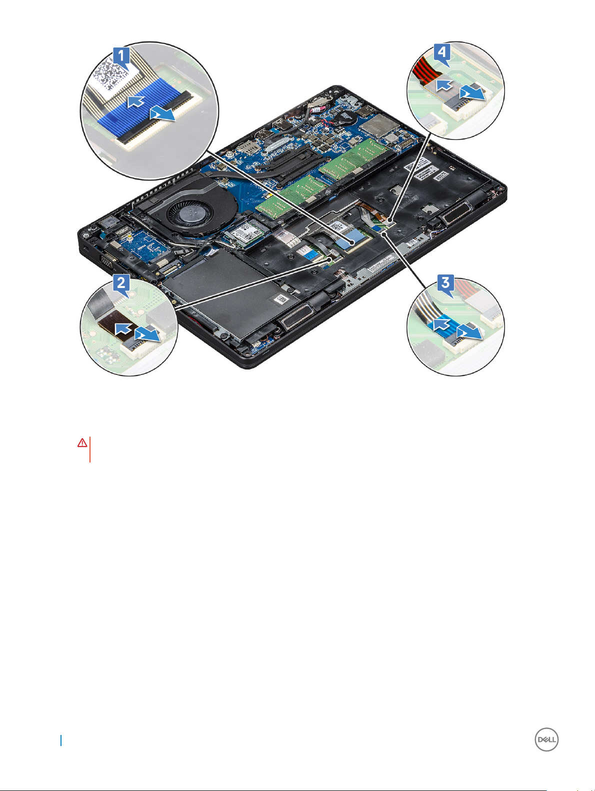
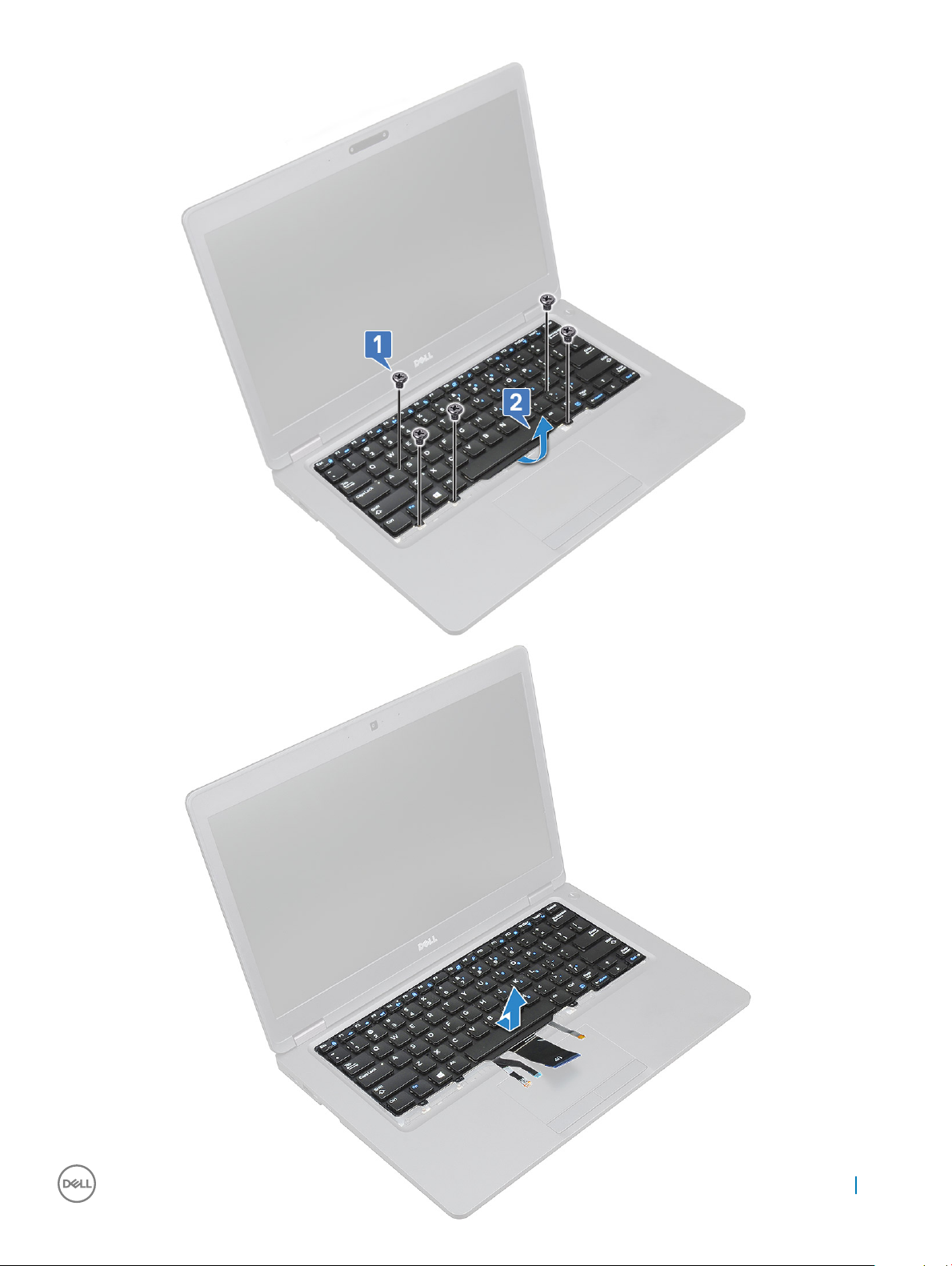
3 To remove the keyboard:
a Lift the latch and disconnect the keyboard cable from the connector on the system [1].
b Lift the latch and disconnect the keyboard backlight cables from the connector on the system [2,3,4].
: Number of cables to disconnect is based on the keyboard type.
NOTE
Removing and installing components 23
Page 24
c Turn over the system and open the laptop in working mode.
d Remove the ve (M2x2.5) screws that secure the keyboard to the system [1].
e Pry the keyboard from the bottom side and lift it away from the system [2] along with the keyboard cable and the keyboard back
light cable.
WARNING
damage to the cables.
: Gently pull the keyboard cable and the keyboard back light cables routed under the system to avoid
24 Removing and installing components
Page 25
Removing and installing components 25
Page 26

Installing the keyboard
1 Hold the keyboard and route the keyboard cable and the keyboard backlight cable through the palmrest in the system.
2 Align the keyboard with the screw holders on the system.
3 Replace the ve (M2x2.5) screws to secure the keyboard to the system.
4 Turn the system and connect the keyboard cable and the keyboard backlight cable to the connector in the system.
5 If you have not removed the battery, you must connect the battery cable to the system board.
6 Install the:
a keyboard lattice
b battery
c base cover
7 Follow the procedure in After working inside your computer.
Heat sink
Removing the heat sink
1 Follow the procedure in Before working inside your computer.
2 Remove the :
a base cover
b battery
3 To remove the heat sink :
a Remove the four (M2x3) screws that secure the heat sink on the system board [2].
NOTE
:
• Remove the heat sink screws in sequential order as indicated on the heat-sink.
b Lift the heat sink away from the system [3].
26
Removing and installing components
Page 27

Installing the heat sink
1 Place the heat sink on the system board.
2 Replace the four (M2x3) screws that secure the heat sink on the system board.
NOTE:
• Replace the heat sink screws in sequential order as indicated on the heat-sink.
Install the :
3
a battery
b base cover
4 Follow the procedure in After working inside your computer.
System fan
Removing the system fan
1 Follow the procedure in Before working inside your computer.
2 Remove the:
a base cover
b battery
c hard drive
d chassis frame
3 To remove the system fan:
a Disconnect the system fan cable from the connector on the system board [1].
b Lift the system fan away from the computer [2].
Removing and installing components
27
Page 28

Installing the system fan
1 Place the system fan into the slot on the computer.
2 Connect the system fan cable to the connector on the system board.
3 Install the:
a chassis frame
b hard drive
c battery
d base cover
4 Follow the procedure in After working inside your computer.
Power connector port
Removing the power connector port
1 Follow the procedure in Before working inside your computer.
2 Remove the :
a base cover
b battery
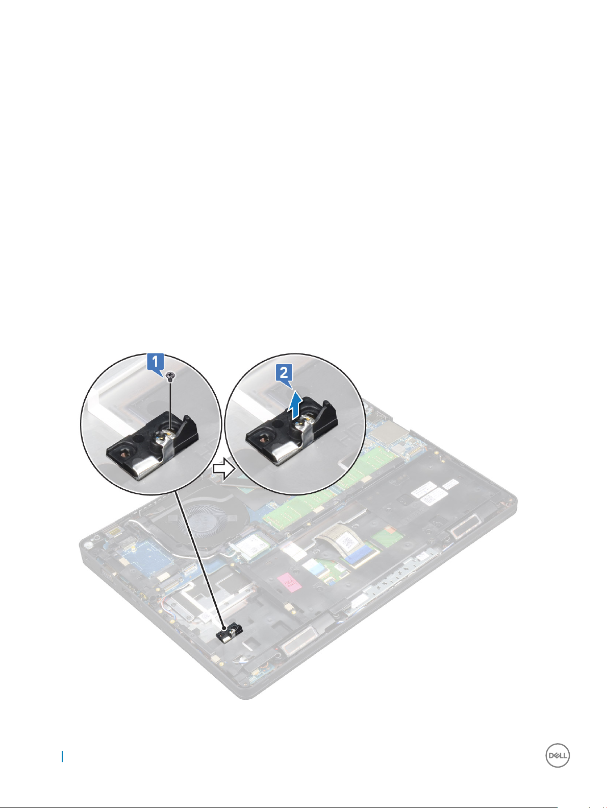
3 To remove the power connector port:
a Remove the screw that secures the display cable on the system board [1].
b Disconnect the power connector cable from the connector on the system board [2].
28
Removing and installing components
Page 29

c Remove the single M2x3 screw to release the power connector bracket that secures the power connector port to your system
[3].
d Remove the power connector bracket from the system [4].
e Pull the power connector port, and lift it away from the system [5].
Installing power connector port
1 Align the power connector port along the grooves on the slot and push it down.
2 Place the metal bracket on the power connector port.
3 Replace the single (M2x3) screw to secure the power connector bracket to the power connector port.
4 Connect the power connector cable to the connector on the system board.
5 Replace the screw that secures the display cable on the system board.
6 Install the :
a battery
b base cover
7 Follow the procedure in After working inside your computer.
Chassis frame
Removing the chassis frame
1 Follow the procedure in Before working inside your computer.
2 Remove the:
Removing and installing components
29
Page 30
a base cover
b battery
c hard drive
d SSD card
e SSD frame
f WLAN card
g WWAN card (optional)
3 To release the chassis frame:
a Release the WLAN cables from the routing channels [1].
b Lift the latch and disconnect the keyboard backlight cable and the keyboard cable from the connector [2,3,4,5] on the system.
NOTE: There may be more than one cable to disconnect based on the keyboard type.
4 To remove the chassis frame:
a Remove the ve (M2x3) screws and eight (M2x5) screws that secure the chassis frame to the system [1].
b Lift the chassis frame away from the system [2].
30
Removing and installing components
Page 31

Installing the chassis frame
1 Place the chassis frame into the slot on the system.
2 Replace the ve (M2x3) screws and eight (M2x5) screws to secure the chassis frame to the system.
3 Connect the keyboard cable and the keyboard backlight cable to the connector on the system.
NOTE
: There may be more than one cable to connect based on keyboard types. The keyboard cables need to go through
the chassis frame not under it.
4 Route the WLAN cables through the routing channels.
5 Install the:
a WWAN card (optional)
b WLAN card
c SSD frame
d SSD card
e hard drive
f battery
g base cover
6 Follow the procedure in After working inside your system.
Removing and installing components
31
Page 32

LED board
Removing LED board
1 Follow the procedure in Before working inside your computer.
2 Remove the .
a base cover
b battery
c hard drive
d SSD card
e SSD frame
f WLAN card
g chassis frame
3 To remove the LED board:
a Lift the latch and remove the LED cable connected to the connector on the LED board [1]
b Remove the (M2.0x2.0) screw that secures the LED board to the system [2].
c Lift the LED board away from the connector [4].
Installing LED board
1 Place the LED board in its slot on the system.
2 Replace the M2.0x2.0 screw to secure the LED board to the system.
32
Removing and installing components
Page 33

3 Connect the LED cable to its connector on the LED board.
4 Install the:
a chassis frame
b WLAN card
c SSD frame
d SSD card
e hard drive
f battery
g base cover
5 Follow the procedure in After working inside your computer.
SmartCard module
Removing smart card reader board
1 Follow the procedure in Before working inside your computer.
2 Remove the:
a base cover
b battery
c hard drive
d SSD card
e SSD frame
f WLAN card
g WWAN card (optional)
h chassis frame
3 To release the smart card reader board:
a Lift the latch and disconnect the smart card reader board cable from the connector [1].
b Lift the latch and disconnect the touchpad cable from the connector [2].
c Peel the cable from the palmrest [3].
Removing and installing components
33
Page 34

4 To remove the smart card reader board:
a Remove the 2 (M2x3) screws that secure the smart card reader board to the palmrest [1].
b Slide and lift the smart card reader from the slot in the system [2].
Installing smart card reader board
1 Insert the smart card reader board to align with the tabs on the chassis.
2 Replace the 2 (M2x3) screws to secure the smart card reader board to the system.
3 Connect the touchpad cable to its connector on the system board.
4 Ax the smart card reader board cable and connect the cable to the connector.
5 Install the:
a chassis frame
b WWAN card (optional)
c WLAN card
d SSD frame
e SSD card
f hard drive
g battery
h base cover
6 Follow the procedure in After working inside your computer.
34
Removing and installing components
Page 35

Speaker
Removing the speaker
1 Follow the procedure in Before working inside your computer.
2 Remove the:
a base cover
b battery
c memory module
d hard drive
e SSD card
f SSD frame
g WLAN card
h WWAN card (optional)
i keyboard lattice
j keyboard
k chassis frame
l system board
3 To remove the speakers:
a Release the speaker cable through the routing channels [1].
b Lift the speaker away from the computer [2].
Removing and installing components
35
Page 36

Installing the speaker
1 Insert the speaker module aligning it with the nodes on the chassis.
2 Route the speaker cable through the routing channels.
3 Install the:
a system board
b chassis frame
c keyboard
d keyboard lattice
e WLAN card
f SSD frame
g SSD card
h hard drive assembly
i memory module
j battery
k base cover
4 Follow the procedure in After working inside your computer.
System board
Removing system board
1 Follow the procedure in Before working inside your computer.
2 Remove the:
a SIM card
b base cover
c battery
d memory module
e hard drive assembly
f SSD card
g SSD frame
h WLAN card
i WWAN card (optional)
j keyboard lattice
k keyboard
l heat sink
m chassis frame
n system fan
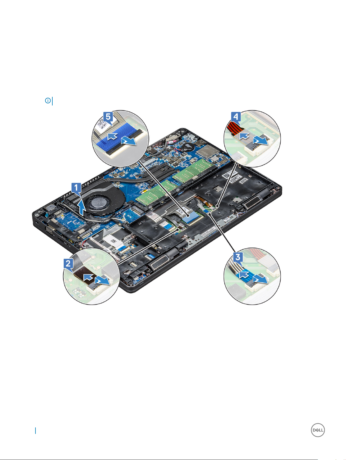
3 Disconnect the following cables from the system board:
a Touchpad cable [1]
b USH cable [2]
c LED board cable [3]
d Speaker cable [4]
36
Removing and installing components
Page 37

4 To release the system board:
a Flip over the system and remove the screw that secures the display cable to the system.
b Flip over the system and remove the two M2x3 screws that secure the display cable bracket in place [1].
c Lift the metal display cable bracket from the system [2].
d Disconnect the display cables from the connectors on the system board [3,4].
e Disconnect the power connector port cable from the connector on the system board 5.
f Remove the two M2x5 screws that secure the type-C USB bracket in place [6].
NOTE
: The metal bracket secures the DisplayPort over USB Type-C.
g Lift the metal bracket away from the system [7].
Removing and installing components
37
Page 38

5 To remove the system board:
a Remove the four (M2x3) screws that secure the system board in place [1].
b Lift the system board away from the system [2].
38
Removing and installing components
Page 39

Installing system board
1 Align the system board with the screw holders on the computer.
2 Replace the four M2x3 screws to secure the system board to the system.
3 Place the metal bracket to secure the DisplayPort over USB Type-C.
4 Replace the two M2x3 screws to secure the metal bracket on the DisplayPort over USB Type-C.
5 Connect the power connector port cable to the connector on the system board.
6 Connect the display cable to the connector on the system board.
7 Place the display cable metal bracket to its place over the display cable.
8 Replace the two M2x3 screws to secure the metal bracket.
9 Connect the following cables:
a Touchpad cable
b LED board cable
c USH board cable
d speaker cable
10 Install the:
a system fan
b chassis frame
c heat sink
d keyboard
e keyboard lattice
f WWAN card (optional)
g WLAN card
h SSD frame
Removing and installing components
39
Page 40

i SSD card
j hard drive
k memory module
l battery
m base cover
n SIM card
11 Follow the procedure in After working inside your computer.
Display hinge cover
Removing display hinge cover
1 Follow the procedure in Before working inside your computer.
2 Remove the:
a base cover
3 Disconnect the battery cable from the system board.
4 To remove the display hinge cover:
a Remove the M2x3 screw that secures the display hinge cover to the chassis [1].
b Lift the display hinge cover away from the display hinge [2].
c Repeat step a and step b to remove the other display hinge cover.
40
Removing and installing components
Page 41

Installing display hinge cover
1 Place the display hinge cover on the display hinge.
2 Replace the M2x3 screw to secure the display hinge cover to the display hinge.
3 Repeat step 1 and step 2 to install the other display hinge cover.
4 Connect the battery cable to its connector on the system board.
5 Install the:
a base cover
6 Follow the procedure in After working inside your computer.
Display assembly
Removing display assembly
1 Follow the procedure in Before working inside your computer.
2 Remove the:
a base cover
b battery
c WLAN card
d WWAN card (optional)
e display hinge cover
3 To disconnect the display cable:
a Release the WLAN and WWAN cables from the routing channels [1].
b Remove the two (M2x3) screws that secure the display cable bracket in place [2].
c Remove the display cable bracket that secures the display cable from the system [3].
d Disconnect the display cables from the connector on the system board [4,5].
e Remove the screw that secures the tape which in turn secures the display cable to the system [6].
Removing and installing components
41
Page 42

4 To release the display assembly:
a Remove the two M2x5 screws that secure the display assembly to the computer [1].
b Release the WLAN cable and display cable through the routing channels [2] [3].
42
Removing and installing components
Page 43

5 Turn over the computer.
6 To remove the display assembly:
a Remove the two M2x5 screws that secure the display assembly to the computer [1].
b Open the display [2].
Removing and installing components
43
Page 44

c Lift the display assembly from the computer.
44
Removing and installing components
Page 45

Installing display assembly
1 Place the chassis on the edge of a plane surface.
2 Align the display assembly to align with the screw holders on the system.
3 Replace the two screws that secures the display assembly.
4 Close the display.
5 Replace the two screws that secures the display assembly.
6 Replace the screw to secure the display cable to the system.
7 Connect the display cable to the connector on the system board.
8 Place the metal bracket to secure the display cable.
9 Replace the (M2x3) screws to secure the metal bracket to the system.
10 Route the WLAN and WWAN cables through the routing channels.
11 Install the:
a hinge cover
b WWAN card (optional)
c WLAN card
d hinge cover
e battery
f base cover
12 Follow the procedure in After working inside your computer.
Removing and installing components
45
Page 46
Display bezel
Removing display bezel
1 Follow the procedure in Before working inside your computer.
2 Remove the:
a base cover
b battery
c WLAN card
d WWAN card (optional)
e Display hinge cover
f display assembly
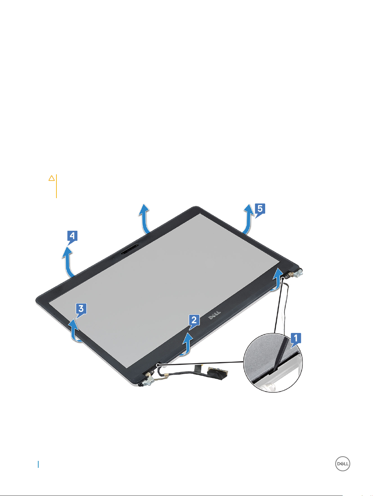
3 To remove the display bezel:
a Pry the display bezel at the base of the display [1].
b Lift the display bezel to release it [2].
c Pry the edges on the side of the display to release the display bezel [3, 4,5].
CAUTION: The adhesive used on the LCD bezel to seal it with the LCD itself, makes it hard to remove the bezel as the
adhesive is very strong and tends to stay stuck to the LCD portion and can peel the layers up or crack the glass when
trying to pry the two items apart.
Installing display bezel
1 Place the display bezel on the display assembly.
46
Removing and installing components
Page 47

NOTE: Remove the protective covering on the adhesive on the LCD bezel before placing on the display assembly.
2 Starting from the top corner, press on the display bezel and work around the entire bezel until it clicks on to the display assembly.
3 Install the:
a display assembly
b display hinge cover
c WWAN card (optional)
d WLAN card
e battery
f base cover
4 Follow the procedure in After working inside your computer.
Display panel
Removing display panel
1 Follow the procedure in Before working inside your computer.
2 Remove the:
a base cover
b battery
c WLAN card
d WWAN card (optional)
e display hinge cover
f display assembly
g display bezel
3 Remove the four M2x3 screws that secure the display panel to the display assembly [1] and lift to turn over the display panel to access
the display cable [2].
Removing and installing components
47
Page 48
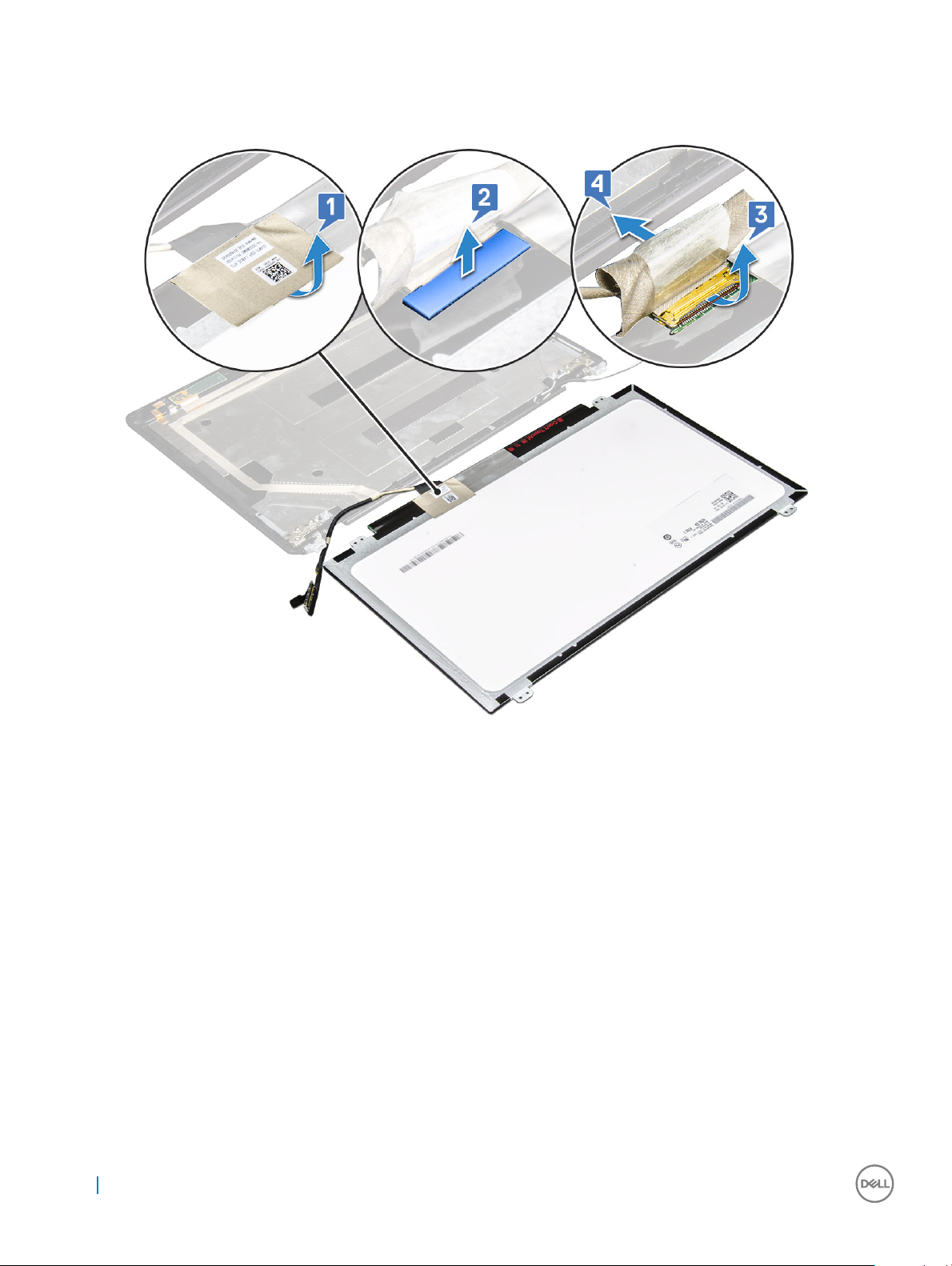
4 To remove the display panel:
a Peel the conductive tape [1].
b Remove the adhesive strip that secures the display cable [2].
c Lift the latch and disconnect the display cable from the connector on the display panel [3] [4].
d Remove the display panel.
Installing display panel
1 Connect the display cable to the connector and ax the adhesive strip.
2 Ax the conductive tape to secure the display cable.
3 Replace the display panel to align with the screw holders on the display assembly.
4 Replace the four M2x3 screws to secure the display panel to the display assembly.
5 Install the:
a display bezel
b display assembly
c display hinge cover
d WLAN card
e WWAN card (optional)
f battery
g base cover
6 Follow the procedure in After working inside your computer.
48
Removing and installing components
Page 49

Display (eDP) cable
Removing display cable
1 Follow the procedure in Before working inside your computer.
2 Remove the:
a base cover
b battery
c WLAN card
d WWAN card (optional)
e display hinge cover
f display assembly
g display bezel
h display panel
3 Disconnect the display cable from the camera [1].
4 Peel the display cable from the adhesive to remove it from the display [2].
Installing display cable
1 Ax the display cable to the display back cover.
2 Ax the conductive tape to the display cable.
3 Install the:
a display panel
b display bezel
c display assembly
d display hinge cover
Removing and installing components
49
Page 50

e WLAN card
f WWAN card (optional)
g battery
h base cover
4 Follow the procedure in After working inside your computer.
Camera
Removing camera
1 Follow the procedure in Before working inside your computer.
2 Remove the:
a base cover
b battery
c WLAN card
d WWAN card (optional)
e display hinge cover
f display assembly
g display bezel
h display panel
3 To remove the camera:
a Disconnect the camera cable from the connector [1].
b Carefully pry and remove the camera module from the display back cover [2].
50
Removing and installing components
Page 51

Installing camera
1 Insert the camera into the slot on the display assembly.
2 Connect the display cable to the connector.
3 Ax the two conductive tape above the camera.
4 Install the:
a display panel
b display bezel
c display assembly
d display hinge cover
e WLAN card
f WWAN card (optional)
g memory module
h battery
i base cover
5 Follow the procedure in After working inside your computer.
Display hinges
Removing display hinge
1 Follow the procedure in Before working inside your computer.
2 Remove the:
a base cover
b battery
c WLAN card
d WWAN card (optional)
e display hinge cover
f display assembly
g display bezel
3 To remove the display hinge:
a Remove the 6 (M2.5x3) screws that secure the display hinge to the display assembly [1].
b Lift the display hinge away from the display assembly [2].
c Repeat step a and step b to remove the other display hinge.
Removing and installing components
51
Page 52

Installing display hinge
1 Place the display hinge on the display assembly.
2 Replace the 6 (M2.5x3) screws to secure the display hinge to the display assembly.
3 Repeat step 1 and step 2 to install the other display hinge.
4 Install the:
a display bezel
b display assembly
c display hinge cover
d WLAN card
e WWAN card (optional)
f battery
g base cover
5 Follow the procedure in After working inside your computer.
Display back cover assembly
Removing the display back cover assembly
1 Follow the procedure in Before working inside your computer.
2 Remove the:
52
Removing and installing components
Page 53

a base cover
b battery
c memory module
d WLAN card
e WWAN card (optional)
f display hinge cover
g display assembly
h display bezel
i display panel
j display hinge
k display cable
l camera
The display back cover assembly is the remaining component, after removing all the components.
Installing the display back cover assembly
1 Place the display back cover assembly on a at surface.
2 Install the:
a camera
b display cable
c display hinge
d display panel
e display bezel
f display assembly
g display hinge cover
h WLAN card
i WWAN card (optional)
j memory module
k battery
l base cover
3 Follow the procedure in After working inside your computer.
Removing and installing components
53
Page 54

Palm rest
Removing palm rest
1 Follow the procedure in Before working inside your computer.
2 Remove the:
a SIM card
b base cover
c battery
d memory module
e hard drive
f SSD card
g SSD frame
h WLAN card
i WWAN card (optional)
j keyboard lattice
k keyboard
l heat sink
m system fan
n chassis frame
o system board
p display hinge cover
q display assembly
3 The palm rest is the remaining component after removing all the components.
54
Removing and installing components
Page 55

Installing palm rest
1 Place the palm rest on a at surface.
2 Install the:
a display assembly
b display hinge cover
c system board
d system fan
e chassis frame
f heat sink assembly
g keyboard
h keyboard lattice
i WWAN card (optional)
j WLAN card
k SSD frame
l SSD card
m hard drive
n memory module
o battery
p base cover
q SIM card
3 Follow the procedure in After working inside your computer.
Removing and installing components
55
Page 56

Technical specications
NOTE: Oerings may vary by region. For more information regarding the conguration of your computer in:
• Windows 10, click or tap Start > Settings > System > About.
Topics:
• Processor
• Memory
• Storage specication
• Audio specications
• Video specication
• Camera option
• Ports and Connectors
• Contactless smart card
• Display specication
• Keyboard specication for Latitude 5490
• Touch pad specications
• Battery specications
• AC Adapter specications
• System dimensions
• Operating Conditions
3
Processor
Your system is built with Intel Dual and Quad Core processors.
Table 2. Processor
Processors Support List UMA Graphics
Intel® Core™ i3-7130U (Dual Core, 3M Cache, 2.7GHz,15W) Intel® HD Graphics 620
Intel® Core™ i5-7300U (Dual Core, 3M Cache, 2.6GHz,15W, vPro) Intel® HD Graphics 620
Intel® Core™ i5-8250U (Quad Core, 6M Cache, 1.6GHz,15W) Intel® UHD Graphics 620
Intel® Core™ i5-8350U (Quad Core, 6M Cache, 1.7GHz,15W, vPro) Intel® UHD Graphics 620
Intel® Core™ i7-8650U ( Quad Core, 8M Cache, 1.9GHz,15W, vPro) Intel® UHD Graphics 620
56 Technical specications
specications
Page 57

Memory
Your computer supports a maximum of 32 GB of memory.
Table 3. Memory specications
Minimum Memory Conguration 4 GB
Maximum Memory Conguration 32 GB
Number of slots 2 SoDIMM)
Maximum memory supported per slot 16 GB
Memory options
• 4 GB — 1 x 4 GB
• 8 GB — 1 x 8 GB
• 8 GB — 2 x 4 GB
• 16 GB — 2 x 8 GB
• 16 GB — 1 x 16 GB
• 32 GB — 2 x 16 GB
Type
Speed
Storage specication
NOTE
: Depending on the conguration you order, you will see either a HDD or M.2 PCIe SSD in your system.
Feature Specication
Storage:
• HDD: 2.5 inch up to 1 TB, Hybrid, OPAL SED options
• SSD M.2 2280 SATA: up to 512 GB, OPAL SED options
• SSD M.2 2230 PCIe/NVMe : up to 512GB
• SSD M.2 2280 PCIe x2 NVMe: up to 1 TB, OPAL SED options
• Dell Fast Response Free Fall Sensor and HDD Isolation (standard feature)
Audio specications
Feature
Specication
DDR4
• 2400 MHz for 8th Gen Processor
• 2133 MHz for 7th Gen Processor
Types High-denition audio
Controller Realtek ALC3246
Internal interface
• Universal Audio Jack
• High Quality Speakers
• Noise reducing array microphones
• Volume control buttons, supports hot-key keyboard button
External interface Stereo headset/mic combo
Technical specications 57
Page 58

Feature Specication
Speakers Two
Volume controls Hot keys
Video specication
integrated
Feature Specication
Type Integrated on system board, hardware accelerated
DSC controller
Data bus Integrated video
External display
support
• Intel HD Graphics 620
• Intel UHD Graphics 620
• Integrated Graphics congurations supports HDMI 1.4 and Discrete graphics congurations support HDMI 2.0
• VGA connector
Discrete
Feature
Type Discrete
UMA controller NVIDIA GeForce® MX130, GDDR5
Bus type Internal PCIe 3.0
Specication
Camera option
This topics lists out the detailed camera specications for your system.
Table 4. Camera
Camera type HD xed focus
IR Camera Optional
Sensor type CMOS sensor technology
Resolution: Motion video Up to 1280 X 720 (1 MP)
Resolution: Still image Up to 1280 X 720 (1 MP)
Imaging rate Up to 30 frames per second
NOTE: The system is oered with no camera in one of the congurations.
58 Technical specications
specication
Page 59

Ports and Connectors
Table 5. Ports and Connectors
USB Three USB 3.1 Gen 1 (one with PowerShare)
One DisplayPort over USB Type-C.
Video One VGA, HDMI 1.4 (UMA) / HDMI 2.0 (Discrete)
Network One RJ-45
Modem NA
Expansion
Smart Card Reader Yes (optional)
Touch Fingerprint Reader Yes (optional)
Contactless card reader Yes (optional)
Audio Universal Audio JAck
Docking
SD 4.0 Memory card reader
High Quality Speakers
Noise reducing array microphones
Volume control buttons, supports hot-key keyboard button
DisplayPort over USB Type C™
Noble Wedge Lock slot
Contactless smart card
Feature
Supported Smart
Cards/Technologies
Specication
FIPS 201 Contacted Smart Card
Display specication
Feature
Type options:
Size 14 inches
Luminance/
Brightness (typical)
Native Resolution 1366 x 768 / 1920 x 1080
Specication
• FHD WVA (1920 x 1080) Anti-glare (16:9) WLED
• HD (1366 x 768) Anti-glare (16:9) WLED
• FHD WVA (1920 x 1080) Embedded Touch Display with Truelife (OTP Lite)
220 nits
Technical specications 59
Page 60

Feature Specication
Refresh Rate 60 Hz
Horizontal Viewing
Angle
Vertical Viewing
Angle
+/- 40 degrees
+10/- 30 degrees
Keyboard specication for Latitude 5490
Table 6. Keyboard specications
Number of keys 82 (US), 83 (UK), 84 (BZ), 86 (JP)
Size Full sized
X= 19.05 mm key pitch
Y= 19.05 mm key pitch
Backlit keyboard option Yes (optional)
Keyboard hot key denitions for Latitude 5490
Table 7. Keyboard hot key
Fn Key Combination Function
Fn+ESC Fn Toggle
Fn+ F1 Speaker Mute
Fn + F2 Volume Down
Fn + F3 Volume Up
Fn + F4 Mic Mute
Fn + F5 Num Lock
Fn + F6 Scroll Lock
Fn + F8 Display Toggle (Win + P)
Fn + F9 Search
Fn + F10
Fn + F11 Brightness down
denitions
Keyboard backlight on/o
Fn + F12 Brightness up
60 Technical specications
Page 61

Fn + Insert Sleep
Fn + Print Screen
Fn + left arrow
Fn + right arrow
FnKey Mode:
Standard = The F1-F12 keys behave as function keys. Holding <Fn> is required to access their secondary functions.
Wireless on/o
Home
End
Touch pad specications
Table 8. Touch Pad specications
Dimensions
Interface Inter-Integrated Circuit
Multi-Touch Support 4 ngers
Supported Gestures Windows 10
Width: 101.7mm
Height: 55.2mm
Cursor moving Supported
Clicking/ tapping Supported
Click and drag Supported
2-nger scroll Supported
2-nger Pinch/ Zoom Supported
2-nger tap (Right Clicking) Supported
3-nger tap (Invoke Cortana) Supported
3-nger swipe up (See all open windows) Supported
3-nger swipe down (Show the desktop) Supported
3-nger swipe right or left (Switch between open windows) Supported
4-nger tap (Invoke Action Center) Supported
4-nger swipe right or left (Switch virtual desktops) Supported
Technical specications 61
Page 62

Battery specications
Feature Specication
Type
42 Whr
51 Whr
68 Whr
• 42 WHr
• 51 WHr
• 68 WHr
• 4 cell Long Cycle Life Battery
• Length: 181mm (7.126 inch)
• Width: 95.9mm (3.78 inch)
• Height: 7.05mm (0.28 inch)
• Weight: 210.00 g
• Length: 181mm (7.126 inch)
• Width: 95.9mm (3.78 inch)
• Height: 7.05mm (0.28 inch)
• Weight: 250.00 g
• Length: 233mm (9.17 inch)
• Width: 95.9mm (3.78 inch)
• Height: 7.05mm (0.28 inch)
• Weight: 340.00 g
Voltage
Life span 300 discharge/recharge cycles
Temperature range
Operating
Non-operating - 20°C to 65°C (- 4°F to 149°F)
Coin cell battery 3 V CR2032 lithium coin cell
42 WHr 11.4 VDC
51 WHr 11.4 VDC
68 WHr 7.6 VDC
• Charge: 0°C to 50°C (32°F to 122°F)
• Discharge: 0°C to 70°C (32°F to 158°F)
• Operating: 0°C to 35°C (32°F to 95°F)
AC Adapter specications
Feature
Type
Specication
• 65 W adapter, 7.4 mm barrel
• 65 W BFR/PVC Halogen Free adapter, 7.4 mm barrel
62 Technical specications
Page 63

Feature Specication
• 90 W adapter, 7.4 mm barrel
Input voltage 100 V AC to 240 V AC
Input current
(maximum)
Adapter size 7.4 mm
Input frequency 50 Hz to 60 Hz
Output current
Rated output
voltage
Temperature range
(Operating)
Temperature range
(Non-Operating)
• 65 W adapter - 1.7 A
• 65 W BFR/PVC Halogen Free adapter - 1.7 A
• 90 W adapter - 1.6 A
• 65 W adapter - 3.34 A (continuous)
• 65 W BFR/PVC Halogen Free adapter - 3.34 A (continuous)
• 90 W adapter - 4.62 A (continuous)
19.5 V DC
0°C to 40°C (32°F to 104°F)
–40°C to 70°C (–40°F to 158°F)
System dimensions
Table 9. System dimensions
Touch
Weight (pounds/kilogram) Start from 3.52 lb / 1.60 kg
Dimensions inches
Height Touch system:
• Front – 20.3 mm (0.8 inch)
• Back – 20.5 mm (0.8 inch)
Non-touch system:
• Front – 20.3 mm (0.8 inch)
• Back – 20.5 mm (0.8 inch)
Width 333.4 mm (13.1 inch)
Depth 228.9 mm (9.0 inch)
Operating Conditions
This topics lists the operating conditions of your system.
Table 10. Operating conditions
Temperature Range
• Operating: 0 °C to 35 °C (32 °F to 95 °F)
Technical specications 63
Page 64

• Storage: -40 °C to 65 °C (-40 °F to 149 °F
Relative humidity
Altitude (maximum)
Shock
Vibration
• Operating : 10 % to 90 % (non-condensing)
• Storage: 0% to 95% (non-condensing)
• Operating : 3048 m (10,000 ft)
• Storage: 10668 m (35,000 ft)
• Operating: 160 G with pulse duration of 2 ms (equivalent to 80
in/sec)
• Storage: 160 G with pulse duration of 2 ms (equivalent to 80 in/
sec)
• Operating: 0.66 Grms
• Storage: 1.33 Grms
64 Technical specications
Page 65

Technology and components
This chapter details the technology and components available in the system.
Topics:
• Power adapter
• DDR4
• HDMI 1.4
• USB features
• USB Type-C
Power adapter
This laptop is shipped with 7.4mm barrel plug on 65 W or 65 W BFR/PVC Halogen Free or 90 W power adapter.
4
WARNING
pull rmly but gently to avoid damaging the cable.
WARNING: The power adapter works with electrical outlets worldwide. However, power connectors and power strips vary
among countries. Using an incompatible cable or improperly connecting the cable to the power strip or electrical outlet may
cause re or equipment damage.
: When you disconnect the power adapter cable from the laptop, grasp the connector, not the cable itself, and then
DDR4
DDR4 (double data rate fourth generation) memory is a higher-speed successor to the DDR2 and DDR3 technologies and allows up to 512
GB in capacity, compared to the DDR3's maximum of 128 GB per DIMM. DDR4 synchronous dynamic random-access memory is keyed
dierently from both SDRAM and DDR to prevent the user from installing the wrong type of memory into the system.
DDR4 needs 20 percent less or just 1.2 volts, compared to DDR3 which requires 1.5 volts of electrical power to operate. DDR4 also supports
a new, deep power-down mode that allows the host device to go into standby without needing to refresh its memory. Deep power-down
mode is expected to reduce standby power consumption by 40 to 50 percent.
DDR4 Details
There are subtle dierences between DDR3 and DDR4 memory modules, as listed below.
Key notch dierence
The key notch on a DDR4 module is in a dierent location from the key notch on a DDR3 module. Both notches are on the insertion edge
but the notch location on the DDR4 is slightly dierent, to prevent the module from being installed into an incompatible board or platform.
Technology and components 65
Page 66

Figure 1. Notch dierence
Increased thickness
DDR4 modules are slightly thicker than DDR3, to accommodate more signal layers.
Figure 2. Thickness dierence
Curved edge
DDR4 modules feature a curved edge to help with insertion and alleviate stress on the PCB during memory installation.
Figure 3. Curved edge
Memory Errors
Memory errors on the system display the new ON-FLASH-FLASH or ON-FLASH-ON failure code. If all memory fails, the LCD does not
turn on. Troubleshoot for possible memory failure by trying known good memory modules in the memory connectors on the bottom of the
system or under the keyboard, as in some portable systems.
HDMI 1.4
This topic explains the HDMI 1.4 and its features along with the advantages.
HDMI (High-Denition Multimedia Interface) is an industry-supported, uncompressed, all-digital audio/video interface. HDMI provides an
interface between any compatible digital audio/video source, such as a DVD player, or A/V receiver and a compatible digital audio and/or
video monitor, such as a digital TV (DTV). The intended applications for HDMI TVs, and DVD players. The primary advantage is cable
reduction and content protection provisions. HDMI supports standard, enhanced, or high-denition video, plus multichannel digital audio on
a single cable.
: The HDMI 1.4 will provide 5.1 channel audio support.
NOTE
66 Technology and components
Page 67

HDMI 1.4 Features
• HDMI Ethernet Channel - Adds high-speed networking to an HDMI link, allowing users to take full advantage of their IP-enabled
devices without a separate Ethernet cable
• Audio Return Channel - Allows an HDMI-connected TV with a built-in tuner to send audio data "upstream" to a surround audio system,
eliminating the need for a separate audio cable
• 3D - Denes input/output protocols for major 3D video formats, paving the way for true 3D gaming and 3D home theater applications
• Content Type - Real-time signaling of content types between display and source devices, enabling a TV to optimize picture settings
based on content type
• Additional Color Spaces - Adds support for additional color models used in digital photography and computer graphics
• 4K Support - Enables video resolutions far beyond 1080p, supporting next-generation displays that will rival the Digital Cinema systems
used in many commercial movie theaters
• HDMI Micro Connector - A new, smaller connector for phones and other portable devices, supporting video resolutions up to 1080p
• Automotive Connection System - New cables and connectors for automotive video systems, designed to meet the unique demands of
the motoring environment while delivering true HD quality
Advantages of HDMI
• Quality HDMI transfers uncompressed digital audio and video for the highest, crispest image quality.
• Low -cost HDMI provides the quality and functionality of a digital interface while also supporting uncompressed video formats in a
simple, cost-eective manner
• Audio HDMI supports multiple audio formats from standard stereo to multichannel surround sound
• HDMI combines video and multichannel audio into a single cable, eliminating the cost, complexity, and confusion of multiple cables
currently used in A/V systems
• HDMI supports communication between the video source (such as a DVD player) and the DTV, enabling new functionality
USB features
Universal Serial Bus, or USB, was introduced in 1996. It dramatically simplied the connection between host computers and peripheral
devices like mice, keyboards, external drivers, and printers.
Let's take a quick look on the USB evolution referencing to the table below.
Table 11. USB evolution
Type Data Transfer Rate Category Introduction Year
USB 3.0/USB 3.1 Gen 1 5 Gbps Super Speed 2010
USB 2.0 480 Mbps High Speed 2000
USB 3.0/USB 3.1 Gen 1 (SuperSpeed USB)
For years, the USB 2.0 has been rmly entrenched as the de facto interface standard in the PC world with about 6 billion devices sold, and
yet the need for more speed grows by ever faster computing hardware and ever greater bandwidth demands. The USB 3.0/USB 3.1 Gen 1
nally has the answer to the consumers' demands with a theoretically 10 times faster than its predecessor. In a nutshell, USB 3.1 Gen 1
features are as follows:
• Higher transfer rates (up to 5 Gbps)
• Increased maximum bus power and increased device current draw to better accommodate power-hungry devices
• New power management features
Technology and components
67
Page 68
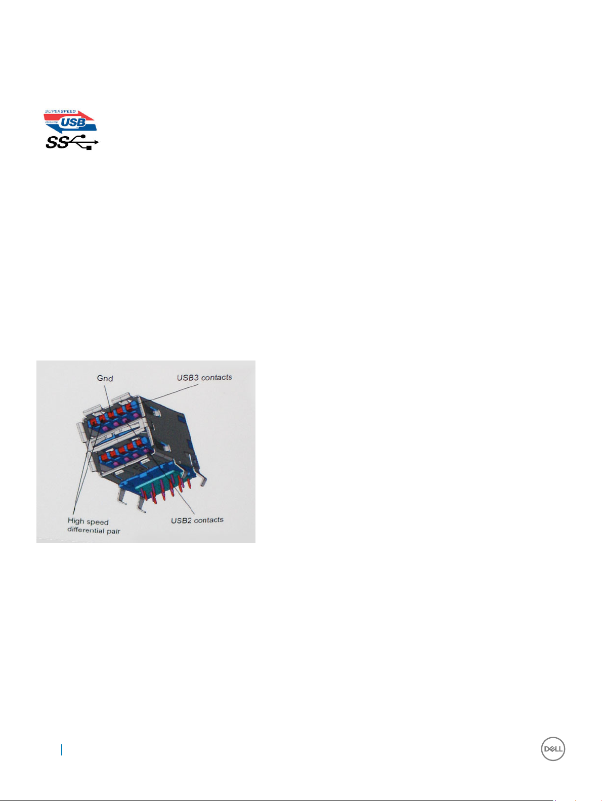
• Full-duplex data transfers and support for new transfer types
• Backward USB 2.0 compatibility
• New connectors and cable
The topics below cover some of the most commonly asked questions regarding USB 3.0/USB 3.1 Gen 1.
Speed
Currently, there are 3 speed modes dened by the latest USB 3.0/USB 3.1 Gen 1 specication. They are Super-Speed, Hi-Speed and FullSpeed. The new SuperSpeed mode has a transfer rate of 4.8Gbps. While the specication retains Hi-Speed, and Full-Speed USB mode,
commonly known as USB 2.0 and 1.1 respectively, the slower modes still operate at 480Mbps and 12Mbps respectively and are kept to
maintain backward compatibility.
USB 3.0/USB 3.1 Gen 1 achieves the much higher performance by the technical changes below:
• An additional physical bus that is added in parallel with the existing USB 2.0 bus (refer to the picture below).
• USB 2.0 previously had four wires (power, ground, and a pair for dierential data); USB 3.0/USB 3.1 Gen 1 adds four more for two pairs
of dierential signals (receive and transmit) for a combined total of eight connections in the connectors and cabling.
• USB 3.0/USB 3.1 Gen 1 utilizes the bidirectional data interface, rather than USB 2.0's half-duplex arrangement. This gives a 10-fold
increase in theoretical bandwidth.
With today's ever increasing demands placed on data transfers with high-denition video content, terabyte storage devices, high megapixel
count digital cameras etc., USB 2.0 may not be fast enough. Furthermore, no USB 2.0 connection could ever come close to the 480Mbps
theoretical maximum throughput, making data transfer at around 320Mbps (40MB/s) — the actual real-world maximum. Similarly, USB
3.0/USB 3.1 Gen 1 connections will never achieve 4.8Gbps. We will likely see a real-world maximum rate of 400MB/s with overheads. At this
speed, USB 3.0/USB 3.1 Gen 1 is a 10x improvement over USB 2.0.
Applications
USB 3.0/USB 3.1 Gen 1 opens up the laneways and provides more headroom for devices to deliver a better overall experience. Where USB
video was barely tolerable previously (both from a maximum resolution, latency, and video compression perspective), it's easy to imagine
that with 5-10 times the bandwidth available, USB video solutions should work that much better. Single-link DVI requires almost 2Gbps
68
Technology and components
Page 69

throughput. Where 480Mbps was limiting, 5Gbps is more than promising. With its promised 4.8Gbps speed, the standard will nd its way
into some products that previously weren't USB territory, like external RAID storage systems.
Listed below are some of the available SuperSpeed USB 3.0/USB 3.1 Gen 1 products:
• External Desktop USB 3.0/USB 3.1 Gen 1 Hard Drives
• Portable USB 3.0/USB 3.1 Gen 1 Hard Drives
• USB 3.0/USB 3.1 Gen 1 Drive Docks & Adapters
• USB 3.0/USB 3.1 Gen 1 Flash Drives & Readers
• USB 3.0/USB 3.1 Gen 1 Solid-state Drives
• USB 3.0/USB 3.1 Gen 1 RAIDs
• Optical Media Drives
• Multimedia Devices
• Networking
• USB 3.0/USB 3.1 Gen 1 Adapter Cards & Hubs
Compatibility
The good news is that USB 3.0/USB 3.1 Gen 1 has been carefully planned from the start to peacefully co-exist with USB 2.0. First of all,
while USB 3.0/USB 3.1 Gen 1 species new physical connections and thus new cables to take advantage of the higher speed capability of
the new protocol, the connector itself remains the same rectangular shape with the four USB 2.0 contacts in the exact same location as
before. Five new connections to carry receive and transmitted data independently are present on USB 3.0/USB 3.1 Gen 1 cables and only
come into contact when connected to a proper SuperSpeed USB connection.
Windows 8/10 will be bringing native support for USB 3.1 Gen 1 controllers. This is in contrast to previous versions of Windows, which
continue to require separate drivers for USB 3.0/USB 3.1 Gen 1 controllers.
Microsoft announced that Windows 7 would have USB 3.1 Gen 1 support, perhaps not on its immediate release, but in a subsequent Service
Pack or update. It is not out of the question to think that following a successful release of USB 3.0/USB 3.1 Gen 1 support in Windows 7,
SuperSpeed support would trickle down to Vista. Microsoft has conrmed this by stating that most of their partners share the opinion that
Vista should also support USB 3.0/USB 3.1 Gen 1.
Super-Speed support for Windows XP is unknown at this point. Given that XP is a seven-year-old operating system, the likelihood of this
happening is remote.
Advantages of Displayport over USB Type-C
• Full DisplayPort audio/video (A/V) performance (up to 4K at 60Hz)
• SuperSpeed USB (USB 3.1) data
• Reversible plug orientation and cable direction
• Backwards compatibility to VGA, DVI with adaptors
• Supports HDMI 2.0a and is backwards compatible with previous versions
USB Type-C
USB Type-C is a new, tiny physical connector. The connector itself can support various exciting new USB standard like USB 3.1 and USB
power delivery (USB PD).
Technology and components
69
Page 70

Alternate Mode
USB Type-C is a new connector standard that's very small. It's about a third the size of an old USB Type-A plug. This is a single connector
standard that every device should be able to use. USB Type-C ports can support a variety of dierent protocols using “alternate modes,”
which allows you to have adapters that can output HDMI, VGA, DisplayPort, or other types of connections from that single USB port
USB Power Delivery
The USB PD specication is also closely intertwined with USB Type-C. Currently, smartphones, tablets, and other mobile devices often use
a USB connection to charge. A USB 2.0 connection provides up to 2.5 watts of power — that'll charge your phone, but that's about it. A
laptop might require up to 60 watts, for example. The USB Power Delivery specication ups this power delivery to 100 watts. It's bidirectional, so a device can either send or receive power. And this power can be transferred at the same time the device is transmitting
data across the connection.
This could spell the end of all those proprietary laptop charging cables, with everything charging via a standard USB connection. You could
charge your laptop from one of those portable battery packs you charge your smartphones and other portable devices from today. You
could plug your laptop into an external display connected to a power cable, and that external display would charge your laptop as you used
it as an external display — all via the one little USB Type-C connection. To use this, the device and the cable have to support USB Power
Delivery. Just having a USB Type-C connection doesn't necessarily mean they do.
70 Technology and components
Page 71

System setup options
NOTE: Depending on the computer and its installed devices, the items listed in this section may or may not appear.
Topics:
• Boot Sequence
• Navigation keys
• System Setup overview
• Accessing System Setup
• General screen options
• System Conguration screen options
• Video screen options
• Security screen options
• Secure Boot screen options
• Intel Software Guard Extensions
• Performance screen options
• Power Management screen options
• POST Behavior screen options
• Manageability
• Virtualization support screen options
• Wireless screen options
• Maintenance screen options
5
Boot Sequence
Boot Sequence allows you to bypass the System Setup–dened boot device order and boot directly to a specic device (for example:
optical drive or hard drive). During the Power-on Self Test (POST), when the Dell logo appears, you can:
• Access System Setup by pressing F2 key
• Bring up the one-time boot menu by pressing F12 key
The one-time boot menu displays the devices that you can boot from including the diagnostic option. The boot menu options are:
• Removable Drive (if available)
• STXXXX Drive
: XXX denotes the SATA drive number.
NOTE
• Optical Drive (if available)
• SATA Hard Drive (if available)
• Diagnostics
: Choosing Diagnostics, will display the ePSA diagnostics screen.
NOTE
The boot sequence screen also displays the option to access the System Setup screen.
System setup options 71
Page 72

Navigation keys
NOTE: For most of the System Setup options, changes that you make are recorded but do not take eect until you restart the
system.
Keys Navigation
Up arrow Moves to the previous eld.
Down arrow Moves to the next eld.
Enter Selects a value in the selected eld (if applicable) or follow the link in the eld.
Spacebar Expands or collapses a drop‐down list, if applicable.
Tab Moves to the next focus area.
NOTE: For the standard graphics browser only.
Esc Moves to the previous page until you view the main screen. Pressing Esc in the main screen displays a message
that prompts you to save any unsaved changes and restarts the system.
System Setup overview
System Setup allows you to:
• Change the system conguration information after you add, change, or remove any hardware in your computer.
• Set or change a user-selectable option such as the user password.
• Read the current amount of memory or set the type of hard drive installed.
Before you use System Setup, it is recommended that you write down the System Setup screen information for future reference.
CAUTION
computer to work incorrectly.
: Unless you are an expert computer user, do not change the settings for this program. Certain changes can cause your
Accessing System Setup
1 Turn on (or restart) your computer.
2 After the white Dell logo appears, press F2 immediately.
The System Setup page is displayed.
NOTE
: If you wait too long and the operating system logo appears, wait until you see the desktop. Then, shut down or
restart your computer and try again.
NOTE: After the Dell logo appears, you can also press F12 and then select BIOS setup.
General screen options
This section lists the primary hardware features of your computer.
Option
System Information This section lists the primary hardware features of your computer.
Description
• System Information: Displays BIOS Version, Service Tag, Asset Tag, Ownership Tag, Ownership Date,
Manufacture Date, and the Express Service Code.
• Memory Information: Displays Memory Installed, Memory Available, Memory Speed, Memory Channels Mode,
Memory Technology, DIMM ASize, DIMM B Size,
72 System setup options
Page 73

Option Description
• Processor Information: Displays Processor Type, Core Count, Processor ID, Current Clock Speed, Minimum
Clock Speed, Maximum Clock Speed, Processor L2 Cache, Processor L3 Cache, HT Capable, and 64-Bit
Technology.
• Device Information: Displays Primary Hard Drive, M.2 SATA2, M.2 SATA, M.2 PCIe SSD-0, LOM MAC Address,
Video Controller, Video BIOS Version, Video Memory, Panel Type, Native Resolution, Audio Controller, Wi-Fi
Device, WiGig Device, Cellular Device, Bluetooth Device.
Battery Information Displays the battery status and the type of AC adapter connected to the computer.
Boot Sequence Allows you to change the order in which the computer attempts to nd an operating system.
• Diskette Drive
• Internal HDD
• USB Storage Device
• CD/DVD/CD-RW Drive
• Onboard NIC
Advanced Boot
Options
UEFI Boot Path
Security
Date/Time Allows you to change the date and time.
This option allows you the legacy option ROMs to load. By default, the Enable Legacy Option ROMs is disabled.
This options controls whether or not the system will prompt the user to enter the Admin password when booting a
UEFI boot path from the F12 Boot Menu.
• Always, Except Internal HDD (enabled by default)
• Always
• Never
System Conguration screen options
Option
Integrated NIC Allows you to congure the integrated network controller. The options are:
SATA Operation Allows you to congure the internal SATA hard-drive controller. The options are:
Description
• Disabled
• Enabled
• Enabled w/PXE: This option is enabled by default.
• Disabled
• AHCI
• RAID On: This option is enabled by default.
Drives Allows you to congure the SATA drives on board. All drives are enabled by default. The options are:
• SATA-0
• SATA-2
• SATA-1
• M.2 PCI-e SSD-0
SMART Reporting This eld controls whether hard drive errors for integrated drives are reported during system startup. This
technology is part of the SMART (Self Monitoring Analysis and Reporting Technology) specication. This option is
disabled by default.
System setup options 73
Page 74

Option Description
• Enable SMART Reporting
USB Conguration
Dell Type-C Dock
Conguration
USB PowerShare This eld congures the USB PowerShare feature behavior. This option allows you to charge external devices using
Unobtrusive Mode This option, when enabled, pressing Fn+F7 turns o all light and sound emissions in the system. To resume normal
Miscellaneous
Devices
This is an optional feature.
This eld congures the integrated USB controller. If Boot Support is enabled, the system is allowed to boot any
type of USB Mass Storage Devices (HDD, memory key, oppy).
If USB port is enabled, device attached to this port is enabled and available for OS.
If USB port is disabled, the OS cannot see any device attached to this port.
The options are:
• Enable USB Boot Support: This option is enabled by default.
• Enable External USB Port: This option is enabled by default.
NOTE: USB keyboard and mouse always work in the BIOS setup irrespective of these settings.
The option Always Allow Dell Docks is enabled by default.
the stored system battery power through the USB PowerShare port. The option "Enable USB Power Share" is not
enabled by default.
operation, press Fn+F7 again. This option is disabled by default.
Allows you to enable or disable the following devices:
• Enable Camera: This option is enabled by default.
• Enable Hard Drive Free Fall Protection: This option is enabled by default.
• Enable Secure Digital (SD) Card: This option is enabled by default.
• Secure Digital (SD) Card Boot
• Secure Digital (SD) Card Read — only Mode
Video screen options
Option
LCD Brightness Allows you to set the display brightness depending up on the power source (On Battery and On AC).
NOTE: The video setting will be visible only when a video card is installed into the system.
Description
Security screen options
Option
Admin Password Allows you to set, change, or delete the administrator (admin) password.
74 System setup options
Description
NOTE: You must set the admin password before you set the system or hard drive password. Deleting the
admin password automatically deletes the system password and the hard drive password.
NOTE: Successful password changes take eect immediately.
Default setting: Not set
Page 75

Option Description
System Password Allows you to set, change or delete the system password.
NOTE: Successful password changes take eect immediately.
Default setting: Not set
Internal HDD-0
Password
Strong Password Allows you to enforce the option to always set strong passwords.
Password
Conguration
Password Bypass Allows you to enable or disable the permission to bypass the System and the Internal HDD password, when they
Password Change Allows you to enable the disable permission to the System and Hard Drive passwords when the admin password is
Allows you to set, change, or delete the Internal HDD-0 password.
NOTE: Successful password changes take eect immediately.
Default setting: Not set
Default Setting: Enable Strong Password is not selected.
NOTE: If Strong Password is enabled, Admin and System passwords must contain at least one uppercase
character, one lowercase character and be at least 8 characters long.
Allows you to determine the minimum and maximum length of Administrator and System passwords.
are set. The options are:
• Disabled
• Reboot bypass
Default setting: Disabled
set.
Default setting: Allow Non-Admin Password Changes is selected.
Non-Admin Setup
Changes
UEFI Capsule
Firmware Updates
TPM 2.0 Security Allows you to enable the Trusted Platform Module (TPM) during POST. The options are:
Allows you to determine whether changes to the setup options are allowed when an Administrator Password is set.
If disabled the setup options are locked by the admin password. The option “Allow Wireless Switch changes" is
disabled by default
Allows yout to control whether this system allows BIOS updates via UEFI capsule update packages.
• Enable UEFI Capsule Firmware Updates (enabled by default)
• TPM On: This option is enabled by default.
• Clear
• PPI Bypass for Enabled Commands
• Attestation Enable (This option is enabled by default)
• Key Storage Enable (This option is enabled by default)
• PPI Bypass for Disable Commands
• PPI Bypass for Clear Commands (This option is enabled by default)
• SHA-256: This option is enabled by default.
• Disabled
• Enabled (This option is enabled by default)
System setup options 75
Page 76

Option Description
NOTE: To upgrade or downgrade TPM1.2/2.0, download the TPM wrapper tool (software).
Computrace Allows you to activate or disable the optional Computrace software The options are:
• Deactivate
• Disable
• Activate
NOTE: The Activate and Disable options will permanently activate or disable the feature and no further
changes will be allowed
CPU XD Support Allows you to enable the Execute Disable mode of the processor.
Enable CPU XD Support (default)
OROM Keyboard
Access
Admin Setup
Lockout
Master Password
Lockout
Allows you to set an option to enter the Option ROM Conguration screens using hotkeys during boot. The options
are:
• Enabled
• One Time Enable
• Disabled
Default setting: Enabled
Allows you to prevent users from entering Setup when an Administrator password is set.
Default Setting: Disabled
Allows you to disable master password support. Hard disk password need to be cleared before the setting can be
changed
• Enable Master Password Lockout
Default setting: Disabled
Secure Boot screen options
Option
Secure Boot Enable This option enables or disables the Secure Boot feature.
Description
• Disabled
• Enabled
Default setting: Enabled.
Expert Key
Management
76 System setup options
Allows you to manipulate the security key databases only if the system is in Custom Mode. The Enable Custom
Mode option is disabled by default. The options are:
• PK (default)
• KEK
• db
• dbx
If you enable the Custom Mode, the relevant options for PK, KEK, db, and dbx appear. The options are:
Page 77

Option Description
• Save to File—Saves the key to a user-selected le
• Replace from File—Replaces the current key with a key from a user-selected le
• Append from File—Adds a key to the current database from a user-selected le
• Delete—Deletes the selected key
• Reset All Keys—Resets to default setting
• Delete All Keys—Deletes all the keys
NOTE: If you disable the Custom Mode, all the changes made will be erased and the keys will restore to
default settings.
Intel Software Guard Extensions
Option Description
Intel SGX Enable This elds species you to provide a secured environment for running code/storing sensitive information in the
context of the main OS. The options are:
• Disabled
• Enabled
• Software Controlled (default)
Enclave Memory
Size
This option sets SGX Enclave Reserve Memory Size. The option are:
• 32 MB
• 64 MB
• 128 MB
Performance screen options
Option
Multi Core Support This eld species whether the process has one or all cores enabled. The performance of some applications
Intel SpeedStep Allows you to enable or disable the Intel SpeedStep feature.
Description
improves with the additional cores.
• All: This option is selected by default.
• 1
• 2
• 3
• Enable Intel SpeedStep
Default setting: The option is enabled.
C-States Control Allows you to enable or disable the additional processor sleep states.
• C states
Default setting: The option is enabled.
Intel TurboBoost Allows you to enable or disable the Intel TurboBoost mode of the processor.
System setup options 77
Page 78

Option Description
• Enable Intel TurboBoost
Default setting: The option is enabled.
Hyper-Thread
Control
Allows you to enable or disable the Hyper-Threading in the processor.
• Disabled
• Enabled
Default setting: Enabled.
Power Management screen options
Option Description
AC Behavior Allows you to enable or disable the computer from turning on automatically when an AC adapter is connected.
Default setting: Wake on AC is not selected.
Enable Intel Speed
Shift Technology
Auto On Time Allows you to set the time at which the computer must turn on automatically. The options are:
the option Enable Intel Speed Shift Technology option is enabled by default.
• Disabled
• Every Day
• Weekdays
• Select Days
Default setting: Disabled
USB Wake Support Allows you to enable USB devices to wake the system from Standby.
NOTE: This feature is only functional when the AC power adapter is connected. If the AC power adapter
is removed during Standby, the system setup removes power from all the USB ports to conserve battery
power.
• Enable USB Wake Support
• Wake on Dell USB-C Dock: This option is enabled by default.
Wireless Radio
Control
Wake on LAN/
WLAN
Allows you to enable or disable the feature that automatically switches from wired or wireless networks without
depending on the physical connection.
• Control WLAN Radio
• Control WWAN Radio
Default setting: The options are disabled.
Allows you to enable or disable the feature that powers on the computer from the O state when triggered by a
LAN signal.
• Disabled
• LAN Only
• WLAN Only
• LAN or WLAN
78 System setup options
Page 79

Option Description
Default setting: Disabled
Block Sleep This option lets you block entering to sleep (S3 state) in operating system environment.
Block Sleep (S3 state)
Default setting: This option is disabled
Peak Shift This option enables you to minimize the AC power consumption during the peak power times of day. After you
enable this option, your system runs only in battery even if the AC is attached.
Advanced Battery
Charge
Conguration
Primary Battery
Charge
Conguration
Type-C Connector
Power
This option enables you to maximize the battery health. By enabling this option, your system uses the standard
charging algorithm and other techniques, during the non-work hours to improve the battery health.
Disabled
Default setting: Disabled
Allows you to select the charging mode for the battery. The options are:
• Adaptive (default)
• Standard — Fully charges your battery at a standard rate.
• ExpressCharge — The battery charges over a shorter period of time using Dell’s fast charging technology. This
option is enabled by default.
• Primarily AC use
• Custom
If Custom Charge is selected, you can also congure Custom Charge Start and Custom Charge Stop.
NOTE: All charging mode may not be available for all the batteries. To enable this option, disable the
Advanced Battery Charge Conguration option.
This option lets you set the maximum power that can be drawn from the Type-C connector.
• 7.5 Watts (default)
• 15 Watts
POST Behavior screen options
Option
Adapter Warnings Allows you to enable or disable the system setup (BIOS) warning messages when you use certain power adapters.
Keypad
(Embedded)
Numlock Enable Allows you to enable the Numlock option when the computer boots.
Fn Key Emulation Allows you to set the option where the Scroll Lock key is used to simulate the Fn key feature.
Description
Default setting: Enable Adapter Warnings
Allows you to choose one of two methods to enable the keypad that is embedded in the internal keyboard.
• Fn Key Only: This option is enabled by default.
• By Numlock
NOTE: When setup is running, this option has no eect. Setup works in Fn Key Only mode.
Enable Numlock. This option is enabled by default.
System setup options 79
Page 80

Option Description
Enable Fn Key Emulation (default)
Fn Lock Options
Fastboot Allows you to speed up the boot process by bypassing some of the compatibility steps. The options are:
Extended BIOS
POST Time
Full Screen Logo This option will display full screen logo if your image match screen resolution
Allows you to let hot key combinations Fn + Esc toggle the primary behavior of F1–F12, between their standard
and secondary functions. If you disable this option, you cannot toggle dynamically the primary behavior of these
keys. The available options are:
• Fn Lock. This option is selected by default.
• Lock Mode Disable/Standard
• Lock Mode Enable/Secondary
• Minimal
• Thorough (default)
• Auto
Allows you to create an additional preboot delay. The options are:
• 0 seconds. This option is enabled by default.
• 5 seconds
• 10 seconds
• Enable Full Screen Logo
Warnings and Error This option will cause the boot process to only pause when warnings or errors are detected.
• Prompt on Warnings and Errors This option is enabled by default.
• Continue on Warnings
• Continue on Warnings and Errors
NOTE: Error deemed critical to the operation of the system hardware will always halt the system.
Manageability
Option
USB The option "Enable USB Provision" is not selected by default.
MEBx Hotkey The option Enable MEBx Hotkey is selected by default.
Description
Virtualization support screen options
Option
Virtualization Allows you to enable or disable the Intel Virtualization Technology.
Description
Enable Intel Virtualization Technology: This option is enabled by default.
VT for Direct I/O Enables or disables the Virtual Machine Monitor (VMM) from utilizing the additional hardware capabilities provided
by Intel® Virtualization technology for direct I/O.
80 System setup options
Page 81

Option Description
Enable VT for Direct I/O: This option is enabled by default.
Trusted Execution This option species whether a Measured Virtual Machine Monitor (MVMM) can utilize the additional hardware
capabilities provided by Intel Trusted Execution Technology. The TPM Virtualization Technology, and Virtualization
technology for direct I/O must be enabled to use this feature.
Trusted Execution: This option is disabled by default.
Wireless screen options
Option Description
Wireless Switch Allows to set the wireless devices that can be controlled by the wireless switch. The options are:
• WWAN
• GPS (on WWAN Module)
• WLAN
• Bluetooth
All the options are enabled by default.
NOTE: For WLAN and WiGig enable or disable controls are tied together and they cannot be enabled or
disabled independently.
Wireless Device
Enable
Allows you to enable or disable the internal wireless devices.
• WWAN/GPS
• WLAN
• Bluetooth
All the options are enabled by default.
Maintenance screen options
Option
Service Tag Displays the Service Tag of your computer.
Asset Tag Allows you to create a system asset tag if an asset tag is not already set. This option is not set by default.
BIOS Downgrade This controls ashing of the system rmware to previous revisions.
Data Wipe This eld allows users to erase the data securely from all internal storage devices. The following is list of devices
Description
• Allows BIOS Downgrade (enabled by default)
aected:
• Internal SATA HDD/SSD
• Internal M.2 SATA SDD
• Internal M.2 PCIe SSD
• Internal eMMC
BIOS Recovery This eld allows you to recover from certain corrupted BIOS conditions from a recover le on the user primary hard
drive or an external USB key.
System setup options 81
Page 82

Option Description
• BIOS Recovery from Hard Drive (enabled by default)
• BIOS Auto-Recovery
• Always perform Integrity Check
82 System setup options
Page 83

This chapter details the supported operating systems along with instructions on how to install the drivers.
Topics:
• Operating system congurations
• Downloading drivers
Operating system congurations
This topic lists the operating system supported by your system.
Table 12. Operating systems
6
Software
Microsoft Windows
Other
Microsoft® Windows 10 Pro 64 bit
Mircosoft® Windows 10 Home 64 bit
Ubuntu 16.04 LTS 64-bit
NeoKylin 6.0 64 bit
Downloading drivers
1 Turn on the notebook.
2 Go to Dell.com/support.
3 Click Product Support, enter the Service Tag of your notebook, and then click Submit.
NOTE
: If you do not have the Service Tag, use the auto detect feature or manually browse for your notebook model.
4 Click Drivers and Downloads.
5 Select the operating system installed on your notebook.
6 Scroll down the page and select the driver to install.
7 Click Download File to download the driver for your notebook.
8 After the download is complete, navigate to the folder where you saved the driver le.
9 Double-click the driver le icon and follow the instructions on the screen.
Chipset driver
The chipset driver helps the system identify the components and install necessary drivers accurately. Verify that the chipset was installed in
the system by checking the below controllers. Many of the common devices are visible under Other Devices if no drivers are installed. The
unknown devices disappear once you install the chipset driver.
Make sure to install the following drivers, some of them may exist by default.
• Intel HID Event Filter Driver
• Intel Dynamic Platform and Thermal Framework Driver
Software 83
Page 84

• Intel serial IO driver
• Management Engine
• Realtek PCI-E memory card
Serial IO driver
Verify if the drivers for Touchpad, IR camera, and keyboard and are installed.
Figure 4. Serial IO driver
Graphics controller driver
Verify if the graphics controller driver is already installed in the computer.
Table 13. Graphics controller driver
Before Installation After Installation
USB drivers
Verify if the USB drivers are already installed in the computer.
84
Software
Page 85

Network drivers
Install the WLAN and Bluetooth drivers from the Dell support site.
Table 14. Network drivers
Before installation After installation
Realtek Audio
Verify if audio drivers are already installed in the computer.
Table 15. Realtek audio
Before Installation After Installation
Serial ATA drivers
Install the latest Intel Rapid Storage driver for best performance. Using the default Windows storage drivers is not recommended. Verify if
the default serial ATA drivers are installed in the computer.
Software
85
Page 86

Security drivers
This section lists the security devices in the Device Manager.
Security device drivers
Verify if the security device drivers are installed in the computer.
Fingerprint sensor drivers
Verify if the Fingerprint sensor drivers are installed in the computer.
86 Software
Page 87

7
Troubleshooting
Enhanced Pre-Boot System Assessment — ePSA diagnostics
The ePSA diagnostics (also known as system diagnostics) performs a complete check of your hardware. The ePSA is embedded with the
BIOS and is launched by the BIOS internally. The embedded system diagnostics provides a set of options for particular devices or device
groups allowing you to:
• Run tests automatically or in an interactive mode
• Repeat tests
• Display or save test results
• Run thorough tests to introduce additional test options to provide extra information about the failed device(s)
• View status messages that inform you if tests are completed successfully
• View error messages that inform you of problems encountered during testing
CAUTION
results or error messages.
NOTE: Some tests for specic devices require user interaction. Always ensure that you are present at the computer terminal
when the diagnostic tests are performed.
: Use the system diagnostics to test only your computer. Using this program with other computers may cause invalid
Running the ePSA diagnostics
1 Power-on the computer.
2 As the computer boots, press the F12 key as the Dell logo appears.
3 On the boot menu screen, select the Diagnostics option.
4 Click the arrow key at the bottom left corner.
Diagnostics front page is displayed.
5 Press the arrow in the lower-right corner to go to the page listing.
The items detected are listed.
6 To run a diagnostic test on a specic device, press Esc and click Yes to stop the diagnostic test.
7 Select the device from the left pane and click Run Tests.
8 If there are any issues, error codes are displayed.
Note the error code and validation number and contact Dell.
Real Time Clock reset
The Real Time Clock (RTC) reset function allows you or the service technician to recover the recently launched model Dell Latitude and
Precision systems from select No POST/No Boot/No Power situations. You can initiate the RTC reset on the system from a power o
state only if it is connected to AC power. Press and hold the power button for 25 seconds. The system RTC reset occurs after you release
the power button.
: If AC power is disconnected from the system during the process or the power button is held longer than 40 seconds, the
NOTE
RTC reset process is aborted.
Troubleshooting 87
Page 88

The RTC reset will reset the BIOS to Defaults, un-provision Intel vPro and reset the system date and time. The following items are
unaected by the RTC reset:
• Service Tag
• Asset Tag
• Ownership Tag
• Admin Password
• System Password
• HDD Password
• Key Databases
• System Logs
The following items may or may not reset based on your custom BIOS setting selections:
• The Boot List
• Enable Legacy OROMs
• Secure Boot Enable
• Allow BIOS Downgrade
88 Troubleshooting
Page 89

8
Contacting Dell
NOTE: If you do not have an active Internet connection, you can nd contact information on your purchase invoice, packing slip,
bill, or Dell product catalog.
Dell provides several online and telephone-based support and service options. Availability varies by country and product, and some services
may not be available in your area. To contact Dell for sales, technical support, or customer service issues:
1 Go to Dell.com/support.
2 Select your support category.
3 Verify your country or region in the Choose a Country/Region drop-down list at the bottom of the page.
4 Select the appropriate service or support link based on your need.
Contacting Dell 89
 Loading...