

Page 1

Dell
TM
XFR D630
Fully Rugged Notebook
Service Manual
Page 2

DellTM XFR D630 Fully Rugged Notebook Service Manual
Page 2 of 106
Revision A01
Notes, Notices, and Cautions
NOTE: A NOTE indicates important information that helps you make better use of your computer.
NOTICE: A NOTICE indicates either potential damage to hardware or loss of data and tells you
how to avoid the problem.
CAUTION: A CAUTION indicates a potential for property damage, personal injury, or
death.
Information in this document is subject to change without notice. Some of the information contained in this
doc ument may not apply to all Dell systems.
© 2008 Dell Inc. All rights reserved.
Reproduction in any manner whatsoever without the written permission of Dell Inc. is strictly forbidden
This document is provided for informational purposes only, and may contain typographical errors and technical
inaccuracies. The content is p r ov i d e d a s is, without express or implied wa rr an tie s o f any kind.
Trademarks used in this text: Dell, the DELL l ogo, and Latitude are registered trademarks of Dell Inc.; DirectVue is a
tra d e mark of Augmentix Corporation; W indows and Windows Vista are registered trademarks of Microsoft Corporation;
Bluetooth is a registered trademark owned by Bluetooth SIG, Inc. and is used by Dell under li cen se .
Other trademarks and trade names may be use d i n this document to refer to either the entities claiming the marks and
names or their products. Dell Inc. di sclaims any proprietary inter e s t i n trademarks and trade names other than its own .
Page 3

DellTM XFR D630 Fully Rugged Notebook Service Manual
Page 3 of 106
Revision A01
Table of Contents
1 BEFORE YOU BEGIN
..................................................................................................... 6
1.1 R
ECOMMENDED TOOLS
.................................................................................................... 6
1.2 T
URNING OFF YOUR COMPUTER
......................................................................................... 6
1.3 B
EFORE WORKING INSI DE YOUR COMPUTER
........................................................................ 6
1.4 S
CREW CHART
............................................................................................................... 8
2 XBAY DEVICES
............................................................................................................ 13
3 HARD DRIVE
................................................................................................................ 14
4 STYLUS, TETHER AND CLIP (DIRECTVUE TOUCH SCREEN DISPLAY OPTION)
... 17
4.1 R
EPL A CI NG TH E STYLUS CLIP
...........................................................................................17
4.2 R
EPL A CI NG TH E STYLUS
..................................................................................................19
5 HANDLE
........................................................................................................................ 19
5.1 R
EMOVING THE HANDLE
..................................................................................................20
5.2 I
NSTALLING THE HANDLE
................................................................................................20
6 PORT COVERS
............................................................................................................. 21
6.1 C
OMMS DOOR
..............................................................................................................21
6.2 D
OCKING DOOR
............................................................................................................22
6.3 VGA D
OOR
..................................................................................................................25
6.4 P
OWER DOOR
...............................................................................................................28
6.5 XB
AY DOOR
.................................................................................................................29
6.6 A
UDIO PORTS/WIFI DOOR
..............................................................................................31
6.7 USB S
IDE DOOR
..........................................................................................................32
6.8 USB R
EAR DOOR
..........................................................................................................34
6.9 PC C
ARD SLOT DOOR
....................................................................................................35
7 HINGE COVER
............................................................................................................. 37
7.1 R
EMOVING THE HINGE COVER
..........................................................................................37
7.2 I
NSTALLING THE HIN G E COVER
........................................................................................39
8 KEYBOARDS
................................................................................................................ 39
8.1 S
TANDARD KEYBOARD
....................................................................................................39
8.2 R
UGGED KEYBOARD
.......................................................................................................41
9 MEMORY
...................................................................................................................... 51
9.1 DIMM A
.....................................................................................................................51
9.2 DIMM B
.....................................................................................................................53
10 DISPLAY ASSEMBLY
................................................................................................ 55
10.1 R
EMOVING THE DISPLAY ASSEMBLY
................................................................................56
10.2 I
NSTALLING THE DISPLAY ASSEMBLY
..............................................................................60
10.3 R
EMOVING THE DISPLAY BEZEL
.....................................................................................62
10.4 I
NSTALLING THE DISPLAY BEZEL
....................................................................................63
10.5 R
EMOVING THE DISPLAY PANEL
.....................................................................................63
10.6 I
NSTALLING THE DISPLAY PANEL
....................................................................................65
10.7 R
EMOVING THE DISPLAY TOP COVE R
..............................................................................66
10.8 I
NSTALLING THE DISPLAY TOP COVER
.............................................................................66
10.9 R
EMOVING THE DISPLAY LATCH
.....................................................................................67
Page 4

DellTM XFR D630 Fully Rugged Notebook Service Manual
Page 4 of 106
Revision A01
10.10 I
NSTALLING THE DISPLA Y LATCH
....................................................................................68
11 INTERNAL CARD WITH BLUETOOTH® WIRELESS TECHNOLOGY
....................... 68
11.1 R
EMOVING THE BLUETOOTH® WIRELESS CARD
................................................................68
11.2 I
NSTALLING THE BLUETOOTH® WIRELESS CARD
...............................................................69
12 WWAN, FCM & SIM CARDS
..................................................................................... 70
12.1 M
OBILE BROADBAND NETW OR K
(WWAN) C
ARD
..............................................................70
12.2 F
LASH CACHE MODULE
................................................................................................73
12.3 S
UBSCRIBER IDENTI TY MODULE
(SIM) C
ARD
...................................................................75
13 COIN-CELL BATTERY
............................................................................................... 76
13.1 R
EMOVING THE COIN-CELL BATTERY
..............................................................................76
13.2 I
NSTALLING THE COIN-CELL BATTERY
.............................................................................77
14 PALM REST
................................................................................................................ 78
14.1 R
EMOVING THE PALM REST
...........................................................................................78
14.2 I
NSTALLING THE PALM REST
.........................................................................................80
15 WIRELESS LOCAL AREA NETWORK (WLAN) CARDS
............................................ 81
15.1 R
EMOVING THE
WLAN C
ARD
........................................................................................81
15.2 I
NSTALLING THE
WLAN C
ARD
.......................................................................................83
16 MODEM
...................................................................................................................... 84
16.1 R
EMOVING THE MODEM
...............................................................................................84
16.2 I
NSTALLING THE MODEM
..............................................................................................85
17 PROCESSOR THERMAL-COOLING ASSEMBLY
....................................................... 85
17.1 R
EMOVING THE PROCESSOR THERMAL-COOLING ASSEMBLY
................................................86
17.2 I
NSTALLING THE PROCESSOR THERMAL-COOLING ASSEMBLY
...............................................87
18 PROCESSOR
.............................................................................................................. 88
18.1 R
EMOVING THE PROCESSOR
..........................................................................................88
18.2 I
NSTALLING THE PROCESSOR
........................................................................................89
19 PC CARD READER
..................................................................................................... 90
19.1 R
EMOVING THE PC CARD CAGE
.....................................................................................91
19.2 I
NSTALLING THE PC CARD CAGE
....................................................................................92
20 SPEAKER
................................................................................................................... 92
20.1 R
EMOVING THE SPEAKER
..............................................................................................92
20.2 I
NSTALLING THE SPEAKER
............................................................................................93
21 FAN
............................................................................................................................ 93
21.1 R
EMOVING THE FAN
....................................................................................................93
21.2 I
NSTALLING THE FAN
...................................................................................................94
22 SYSTEM BOARD
........................................................................................................ 95
22.1 R
EMOVING THE SYSTEM BOARD
.....................................................................................95
22.2 I
NSTALLING THE SYSTEM BOARD
...................................................................................98
23 FLASHING THE BIOS
............................................................................................. 101
23.1 F
LASHING THE
BIOS F
ROM A
CD
................................................................................ 101
23.2 F
LASHING THE
BIOS F
ROM THE HARD DRIVE
................................................................. 101
Page 5

DellTM XFR D630 Fully Rugged Notebook Service Manual
Page 5 of 106
Revision A01
24 RF PASSTHRU BOARD
........................................................................................... 102
24.1 R
EMOVING THE RF PASSTHRU BOARD
........................................................................... 102
24.2 I
NSTALLING THE RF PASSTHRU BOARD
......................................................................... 103
25 BOTTOM CHASSIS
.................................................................................................. 104
25.1 R
EMOVING THE BOTTOM CHASSIS
................................................................................ 104
25.2 I
NSTALLING THE BOTTOM CHASSIS
.............................................................................. 105
25.3 R
EMOVING THE MODEM CABLE
.................................................................................... 105
25.4 I
NSTALLING THE MODEM CABLE
................................................................................... 105
Page 6

DellTM XFR D630 Fully Rugged Notebook Service Manual
Page 6 of 106
Revision A01
1 Before You Begin
This chapter provides procedures for removing and installing the components in your computer.
Unless otherwise noted, each procedure assumes that the following:
• You have performed the steps in
91H
Turning Off Your Computer
and
92H
Before Working Inside Your
Computer
.
• You have read the safety information in the XFR D630 Product Information Guide and in the
XFR D630 User’s Guide.
• A component can be replaced by performing the removal procedure in reverse order.
1.1 Recommended Tools
The procedures in this document may require the following tools:
• Small flat-blade screwdriver
• Phillips screwdriver
• Small plastic scribe
• 5-mm hex nut driver
• Flash BIOS-update program CD
• Processor extraction tool
• Torque driver capable of up to 1.5 inches/pound
• Display grommet tool (used when replacing the
93H
Display Assembly
or the
94H
Display Top Cover
Assembly
)
1.2 Turning Off Your Computer
NOTICE: To avoid losing data, save and close any open files and exit any open programs before
you turn off your computer.
1. Shut down the operating system:
a. Save and close any open files, exit any open programs
b. Click Start→ Shut Down→ Shut down.
The computer turns off after the operating system shutdown process finishes.
2. Ensure that the computer and any attached devices are turned off. If your computer and
attached devices do not automatically turn off when you shut down your operating system,
press and hold the power button for 4 seconds.
1.3 Before Working Inside Your Computer
Use the following safety guidelines to help protect your computer from potential damage and to help
ensure your own personal safety.
CAUTION: Before you begin any of the procedures in this section, follow the safety
instructions in the XFR D630 Product Information Guide and in the XFR D630 User’s
Guide.
CAUTION: Handle components and cards with care. Do not touch the components or
contacts on a card. Hold a card by its edges or by its metal mounting bracket. Hold a
component such as a processor by its edges, not by its pins.
NOTICE: Only a certified service technician should perform repairs on your computer. Damage
due to servicing that is not authorized by Dell is not covered by your warranty.
NOTICE: When you disconnect a cable, pull on its connector or on its pull-tab, not on the cable
Page 7
DellTM XFR D630 Fully Rugged Notebook Service Manual
Page 7 of 106
Revision A01
itself. Some cables have a connector with locking tabs; if you are disconnecting this type of cable,
press in on the locking tabs before you disconnect the cable. As you pull connectors apart, keep
them evenly aligned to avoid bending any connector pins. Also, before you connect a cable,
ensure that both connectors are correctly oriented and aligned.
NOTICE: To avoid damaging the computer, perform the following steps before you begin working
inside the computer.
1. Ensure that the work surface is flat and clean to prevent the computer cover from being
scratched.
2. Turn off your computer (see
95H
Turning Off Your Computer
).
NOTICE: To disconnect a network cable, first unplug the cable from your computer and then
unplug it from the network device.
3. Disconnect any telephone, network. And USB cables from the computer.
4. Disconnect your computer and all attached devices from their electrical outlets.
5. Turn over the computer.
NOTICE: To avoid damaging the system board, you must remove the main battery before you
service the computer.
6. Remove the battery.
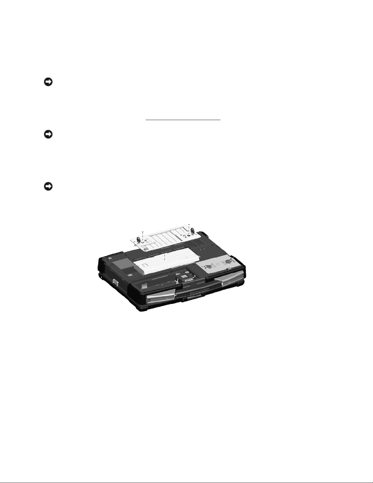
a. If the 2 screws that secure the quarter-turn latches are installed, remove the 2 screws
on the latches on the battery compartment using a #1 Philips screw driver. See the
figure above for the location of the battery compartment. If the 2 security screws are
not installed, proceed to step b.
b. Lift each latch and turn each a quarter-turn, toward the ‘unlock’ icon, to release the
latching mechanism. Remove the compartment cover from the computer.
c. To remove the battery from the compartment, utilize the tab on the battery to assist
in lifting the battery from the compartment.
7. Press the power button to ground the system board.
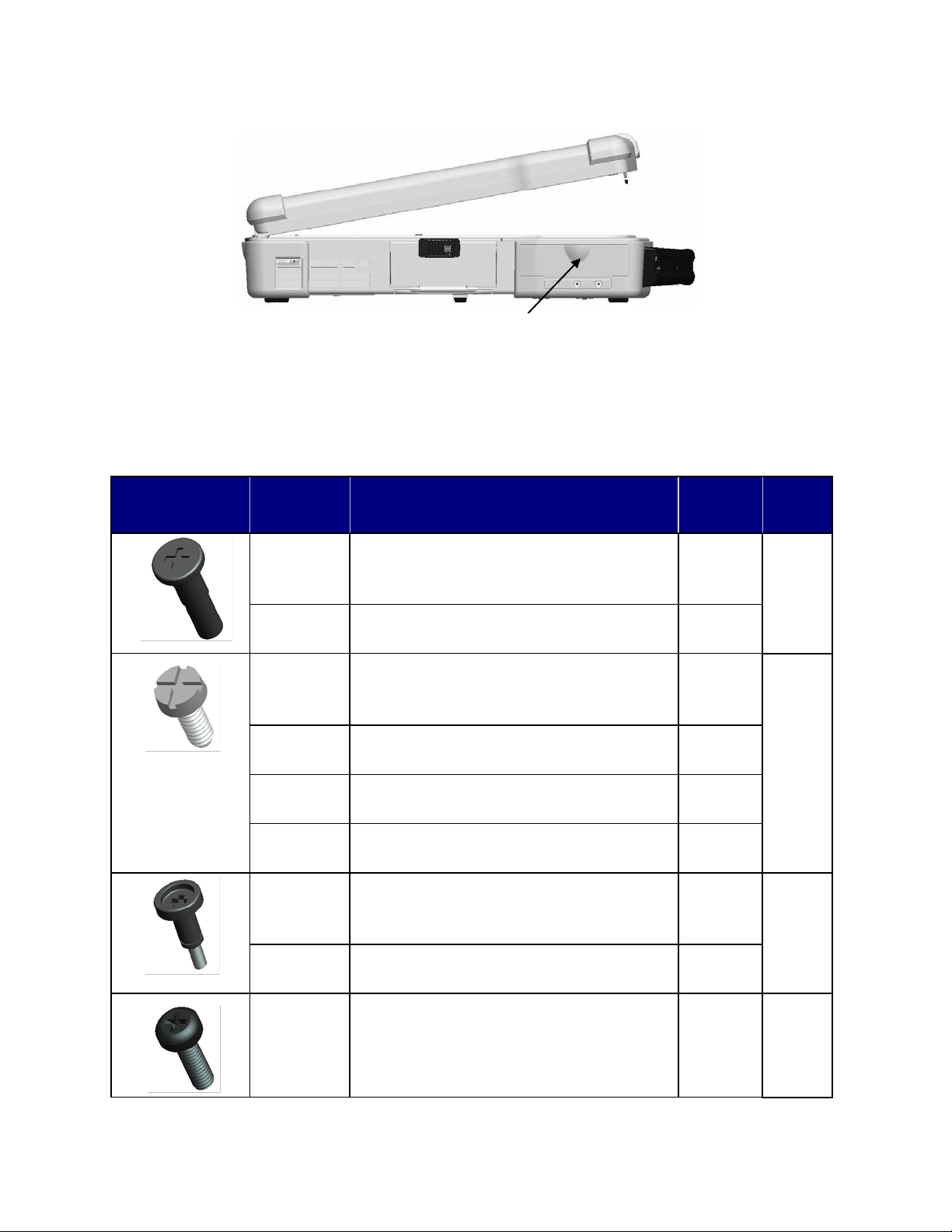
8. Remove any PC Card or ExpressCard, if installed, from the PC Card slot.
a. The PC Card slot is located on the left, front side of the notebook.
b. To access the PC Card or ExpressCard, lower the protective door.
Page 8
DellTM XFR D630 Fully Rugged Notebook Service Manual
Page 8 of 106
Revision A01
c. Remove the PC Card or Express Card.
d. Then close the protective door.
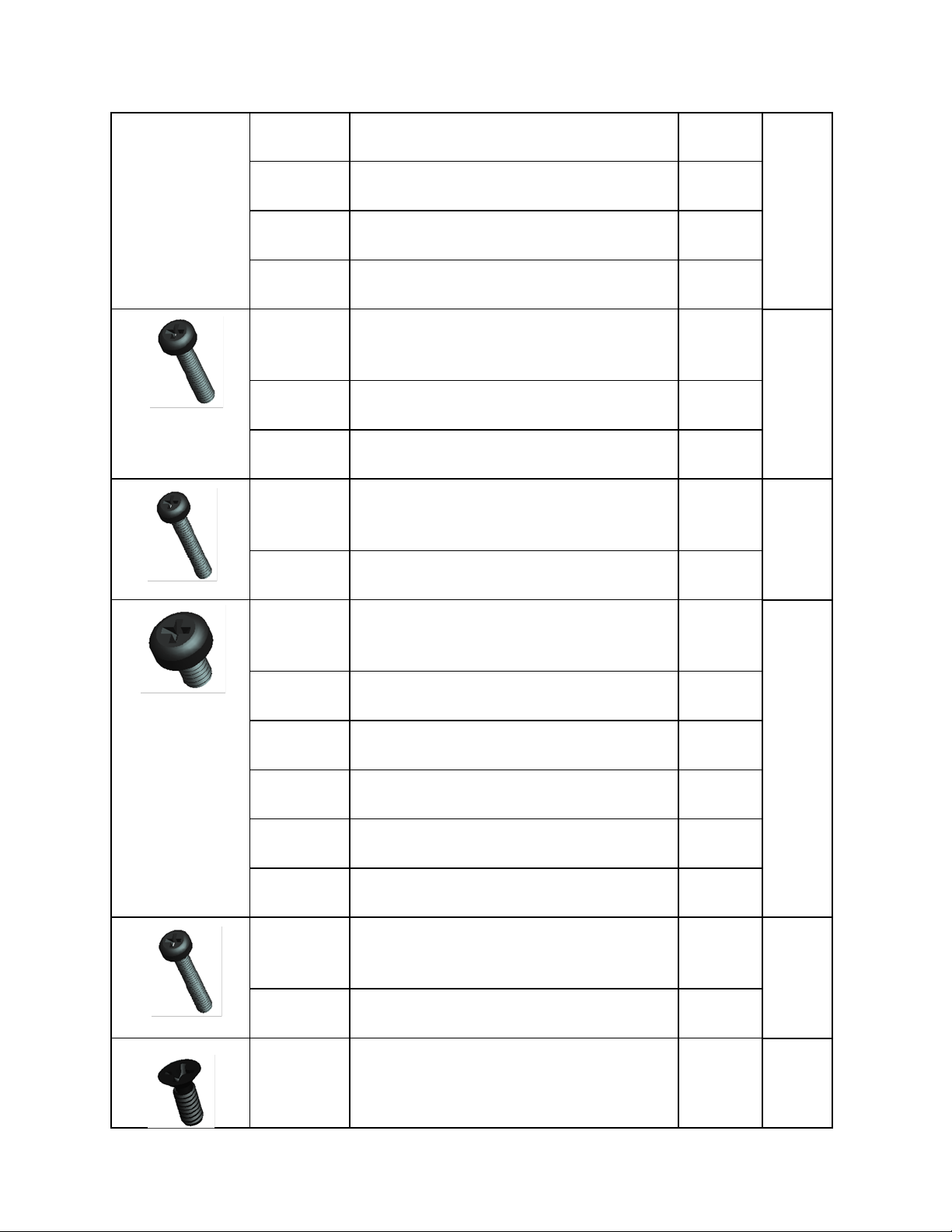
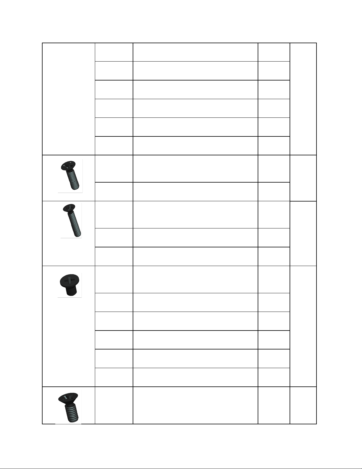
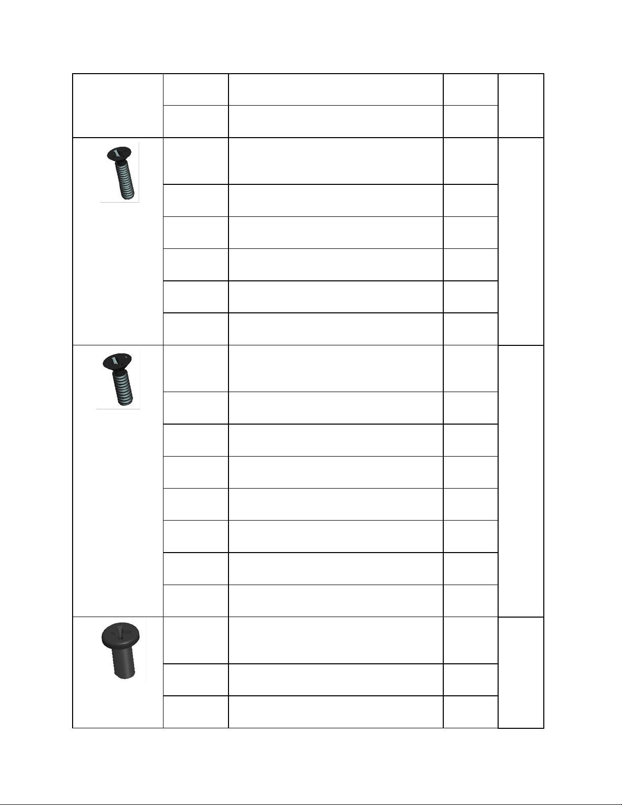
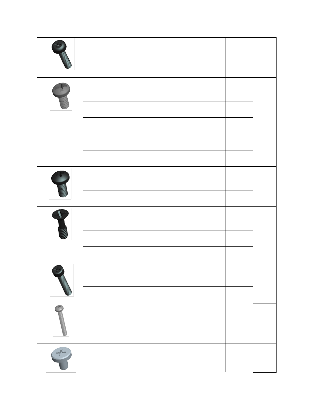
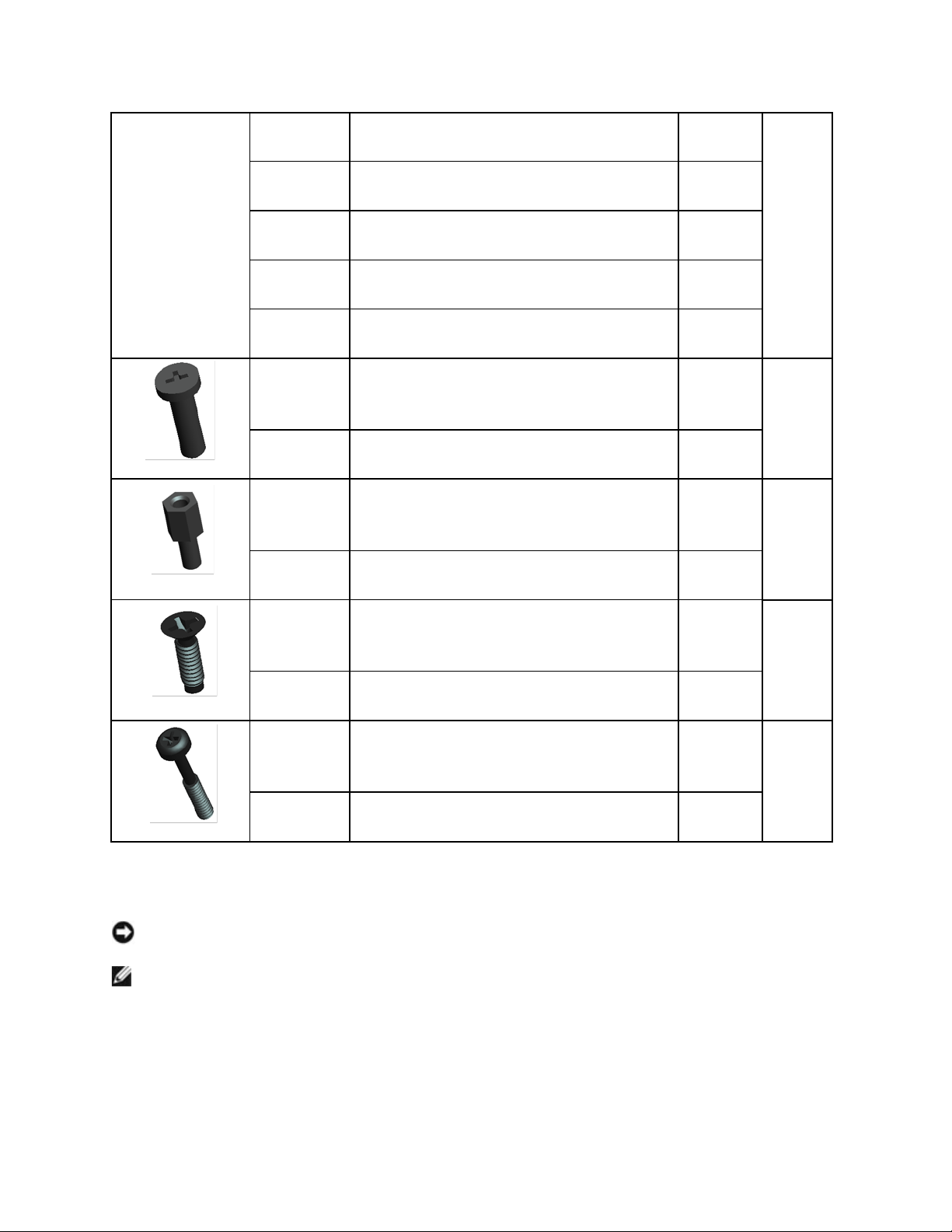
1.4 Screw Chart
SCREW IMAGE
P A R T
NUMBER
DESCRIPTION
Qty/Assy
Total
Qty
18114
SHOULDER SCREW M2.5
6
18815
XFR LCD ASSY TOUCH SCREEN
6
18279
CHEESE HEAD SCREW M1.2 X 3
3
18806
AV DOOR ASSY
1
18808
VGA DOOR ASSY
1
18812
DVD DOOR ASSY
1
18353
SHOULDER SCREW-HEAT SPREADER
3
18035
HEAT SINK ASSY
3
18415
PAN HEAD SCREW M2.5 X 8 -BL AC K
19
PC Card Slot
Page 9
DellTM XFR D630 Fully Rugged Notebook Service Manual
Page 9 of 106
Revision A01
18815
XFR LCD ASSY TOUCH SCREEN
4
18802
PALMREST ASSY
11
18043
ASSY HANDLE WITH HOLDER
2
18619
LCD LATCH ASSY
2
18416
SCR,M3X14,PHH,MSCR,ZPS,XFR
8
18044
ASSY HANDLE
6
18824
SHOULDER STRAP ASSY
2
18417
PAN HEAD SCREW M2 X 12 -BLACK
7
18815
XFR LCD ASSY TOUCH SCREEN
7
18419
PAN HEAD SCREW M2.5 X 4 -BL AC K
12
18810
HDD DOOR ASSY
4
18813
RJ DOOR ASSY
3
18814
USB PLASTIC DOOR ASSY
1
18034
FAN ASSY
3
9999-8024
PCMCIA HOLDER
1
18420
PAN HEAD SCREW M2.5 X 14 -BLACK
1
18802
PALMREST ASSY
1
18423
CSK SCREW M2 X 5 -BLACK
22
Page 10
DellTM XFR D630 Fully Rugged Notebook Service Manual
Page 10 of 106
Revision A01
18806
AV DOOR ASSY
4
18810
HDD DOOR ASSY
2
18804
FAN COVER
4
18807
BATTERY DOOR ASSY
2
18811
DOCKING DOOR ASSY
6
18623
KEYBOARD ASSY
4
18424
CSK SCREW M3 X 10 -B L AC K
4
18043
ASSY HANDLE WITH HOLDER
4
18425
CSK SCREW M2 X 10 -B L AC K
4
18043
ASSY HANDLE WITH HOLDER
2
18044
ASSY HANDLE
2
18426
CSK SCREW M2 X 3 -BLACK
10
18806
AV DOOR ASSY
2
18808
VGA DOOR ASSY
2
18812
DVD DOOR ASSY
2
18802
PALMREST ASSY
2
18618
AV DOOR COVER ASSY
2
18427
CSK SCREW M2.5 X 6 -B L A C K
3
Page 11
DellTM XFR D630 Fully Rugged Notebook Service Manual
Page 11 of 106
Revision A01
18808
VGA DOOR ASSY
1
18812
DVD DOOR ASSY
2
18428
CSK SCREW M2 X 8 -BLACK
10
18815
XFR LCD ASSY TOUCH SCREEN
2
18808
VGA DOOR ASSY
2
18802
PALMREST ASSY
2
18813
RJ DOOR ASSY
2
18814
USB PLASTIC DOOR ASSY
2
18429
CSK SCREW M2 X 6 -BLACK
30
18810
HDD DOOR ASSY
2
18807
BATTERY DOOR ASSY
2
18630
USB SIDE DOOR ASSY
2
18809
DIMMS DOOR ASSY
4
18631
POWER DOOR ASSY
2
18632
PCMCIA DOOR ASSY
3
18628
RUBBER KEYBOARD ASSY
15
18444
SCR,M2.5X5,PHH,TF,BCS
10
18815
XFR LCD ASSY TOUCH SCREEN
6
18803
MOTHERBOARD TO CHASSIS
4
Page 12
DellTM XFR D630 Fully Rugged Notebook Service Manual
Page 12 of 106
Revision A01
18451
PAN HEAD SCREW M2 X 8-B L A C K
1
18802
PALMREST ASSY
1
18477
PANHEAD SCREW M2X4
9
18802
PALMREST ASSY
1
18043
ASSY HANDLE WITH HOLDER
4
18803
RF PASS THROUGH
2
18819
LCD TOP COVER ASSY
2
18517
SCR,M3X6,PHH,MSCR,ZPS,XFR
2
18044
ASSY HANDLE
2
18535
CSK CAPTIVE SCREW M2 X 6
19
18623
KEYBOARD ASSY
15
18816
HINGE COVER ASSY
4
18539
PAN HEAD SCREW M3 X 14 -BLACK
1
18629
STYLUS KIT ASSY
1
18550
PAN HEAD SCREW M3 X 22 -BLACK
2
18824
SHOULDER STRAP ASSY
2
18590
SCREW,KYBD BLK, PAN HEAD M2X3
19
Page 13
DellTM XFR D630 Fully Rugged Notebook Service Manual
Page 13 of 106
Revision A01
18815
XFR LCD ASSY TOUCH SCREEN
8
18802
PALMREST ASSY
2
18803
CARD CAGE ON BASE CHASSIS
4
18623
KEYBOARD ASSY
3
18823
MOTHERBOARD ASSY
2
18591
PAN HEAD SCREW M2.5X8
2
18802
PALMREST ASSY
2
18634
JACK SCREW FOR VGA PORT COVER
4
18617
VGA SUPPORT ASSY
4
18642
CSK SCREW M2 X 6.6
4
18802
PALMREST ASSY
4
18671
P A N H E A D C A P T I V E SC R E W -DVD M2 X
12
1
18804
CHASSIS GASKET ASSY
1
2 XBay Devices
NOTICE: To prevent damage to devices, store them in a safe, dry place when they are not
installed in the computer. Avoid pressing down on them or placing heavy objects on top of them.
NOTE: If the device locking screw is not present, you can remove and install devices while the
computer is running and connected to a docking device (docked).
1. If present, remove the device locking screw from the bottom of the computer.
2. If the computer is running, double-click the Safely Remove Hardware icon on the taskbar,
click the device you want to eject, and click Stop.
3. Press the device latch release.
Page 14

DellTM XFR D630 Fully Rugged Notebook Service Manual
Page 14 of 106
Revision A01
1
Optical drive
2
Device Latch release
4. Pull the device out of the XBay.
To install a device, push the new device into the XBay until it clicks into place.
3 Hard Drive
CAUTION: If you remove the hard drive from the computer when the drive is hot, do
not touch the metal housing of the hard drive.
CAUTION: Before working inside your computer, follow the safety instructions in the
XFR D630 Product Information Guide and in the XFR D630 User’s Guide.
NOTICE: To prevent data loss, turn off your computer before removing the hard drive. Do not
remove the hard drive while the computer is on, in standby mode, or in hibernate mode
NOTICE: Hard drives are extremely fragile; even a slight bump can damage the drive.
NOTE: Dell does not guarantee compatibility or provide support for hard drives from sources
other than Dell.
NOTE: You need the Operating System media to install the Microsoft® Windows® operating
system. You also need the Drivers and Utilities media for your computer to install the drivers and
utilities on the new hard drive.
To replace the hard drive in the hard disk drive compartment:
1. Follow the procedures in
96H
Before You Begin
.
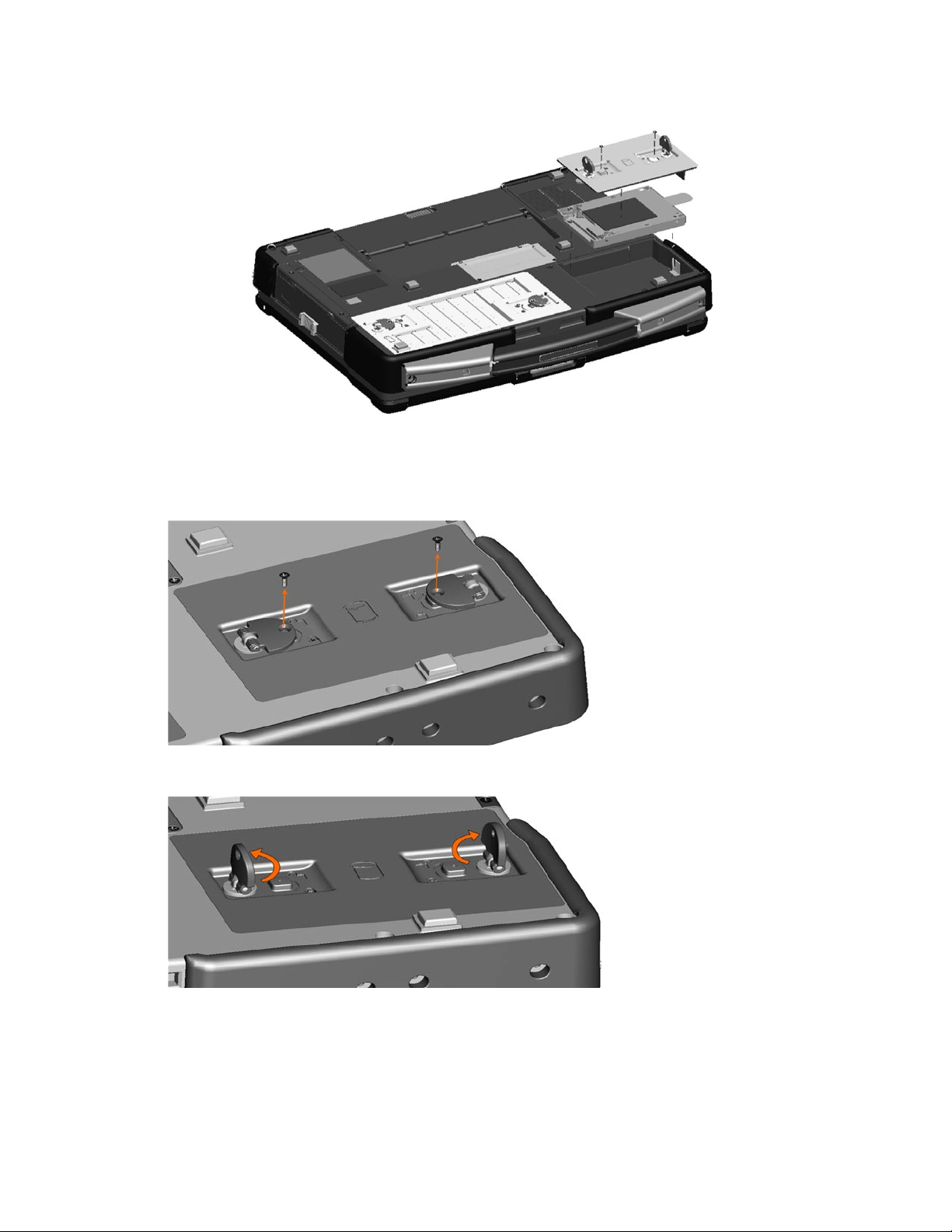
2. Turn the computer over and locate the hard disk drive compartment using the figure below.
Page 15
DellTM XFR D630 Fully Rugged Notebook Service Manual
Page 15 of 106
Revision A01
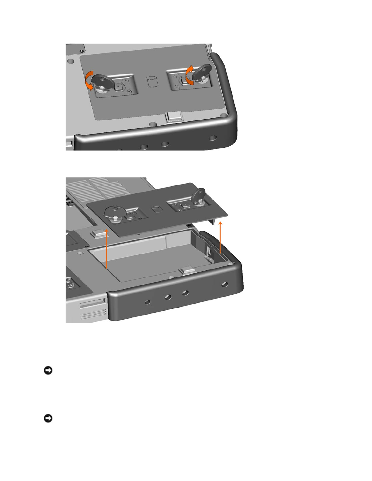
3. If the 2 optional screws that secure the quarter-turn latches are installed, remove the 2
screws on the latches on the hard disk drive compartment using a #1 Philips screw driver. If
the 2 security screws are not installed, proceed to step 4.
4. Lift each latch,
and turn each a quarter-turn, towards the ‘unlock’ icon, to release the latching mechanism.
Page 16
DellTM XFR D630 Fully Rugged Notebook Service Manual
Page 16 of 106
Revision A01
5. Remove the compartment cover from the computer.
6. Locate the tab on the hard disk drive and pull it back to disconnect the hard disk drive from
the motherboard.
7. Continue to utilize the tab to assist in removing the hard disk drive from the compartment.
NOTICE: When the hard drive is not in the computer, store it in protective antistatic packaging.
8. Remove the new drive from its packaging.
Save the original packaging for storing or shipping the hard drive.
NOTICE: Use firm and even pressure to slide the drive into place. If you use excessive force, you
may damage the connector.
Page 17
DellTM XFR D630 Fully Rugged Notebook Service Manual
Page 17 of 106
Revision A01
9. Slide the hard drive into the bay until it is fully seated.
10. Replace and secure the hard disk drive compartment cover with the quarter-turn latches.
11. Use the Operating System CD to install the operating system for your computer (see the XFR
D630 User’s Guide for information).
12. Use the Drivers and Utilities CD to install the drivers and utilities for your computer (see the
XFR D630 User’s Guide for information).
4 Stylus, Tether and Clip (DirectVue Touch
Screen Display option)
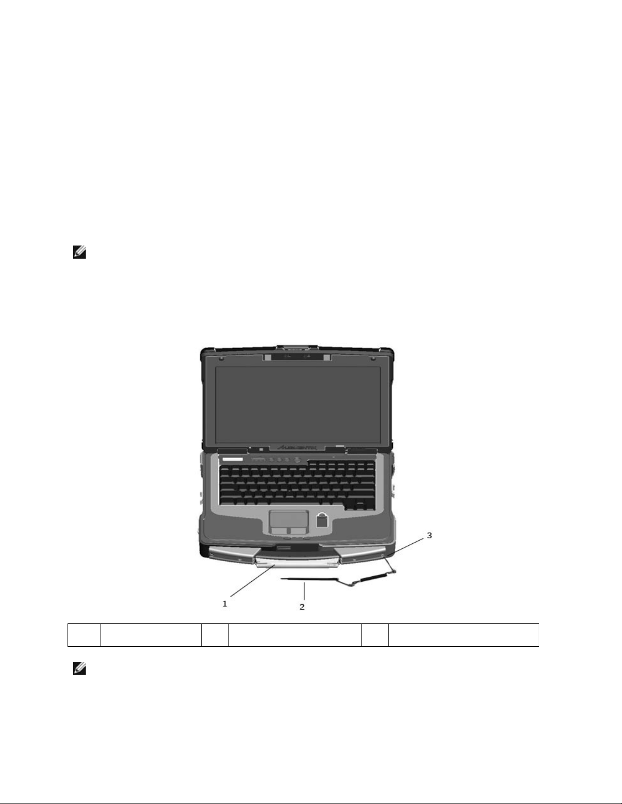
NOTE: Only Touch Screen Display configurations will include the stylus, stylus housing, tether
and stylus clip. The Touch Screen Display is an optional feature.
If your XFR D630 is configured with the DirectVue Touch Screen Display, it will also be equipped with
the optional stylus housing, stylus, stylus tether, and stylus clip.
To replace the stylus, stylus tether or stylus clip, follow the directions provided in the sections below.
1
Stylus housing
2
Stylus and stylus tether
3
Stylus clip (for connection to
the notebook)
NOTE: The stylus clip can be installed on either the left or right side of the handle to allow for
right or left-handed use.
4.1 Replacing the Stylus Clip
Page 18
DellTM XFR D630 Fully Rugged Notebook Service Manual
Page 18 of 106
Revision A01
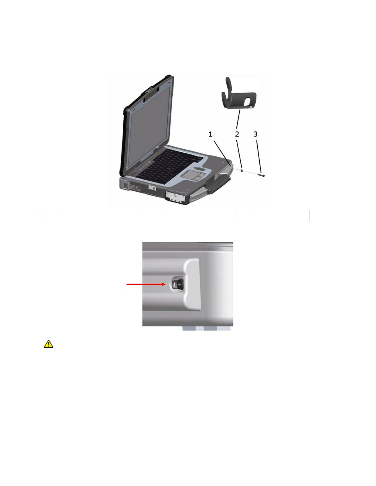
The stylus clip is installed on the handle assembly’s end screw on the left or right side of the
notebook. The stylus clip provides an eyelet into which the stylus tether can be routed to attach the
stylus and stylus tether to the notebook
1
Handle cover
2
Stylus clip
3
Screw
Close Up View of Installed Stylus Clip
CAUTION: Care is needed when installing this clip. The clip is installed with the raised
part towards the center of the notebook so that the raised part of the clip is within the
recessed area of the handle cover. If the clip is installed the opposite way, this raised
metal part of the clip is now above the handle cover housing, and you can easily cut or
injure yourself.
To replace the stylus clip:
1. Loosen the screw on the end of the handle cover that secures the stylus clip. Note that the
stylus clip can be installed on the end of either handle cover to allow for right or left-handed
use.
2. Slide the old stylus clip from beneath the loosened screw.
3. Slide the new stylus clip between the handle cover and the screw.
Page 19
DellTM XFR D630 Fully Rugged Notebook Service Manual
Page 19 of 106
Revision A01
4. Tighten the screw, ensuring the screw head secures the stylus clip in place.
NOTE: If you relocate the stylus from one side of the handle to the other, remember to tighten
the screw that was loosened in step 1.
NOTE: The stylus clip can be installed on either the left or right side of the handle to allow for
right or left-handed use.
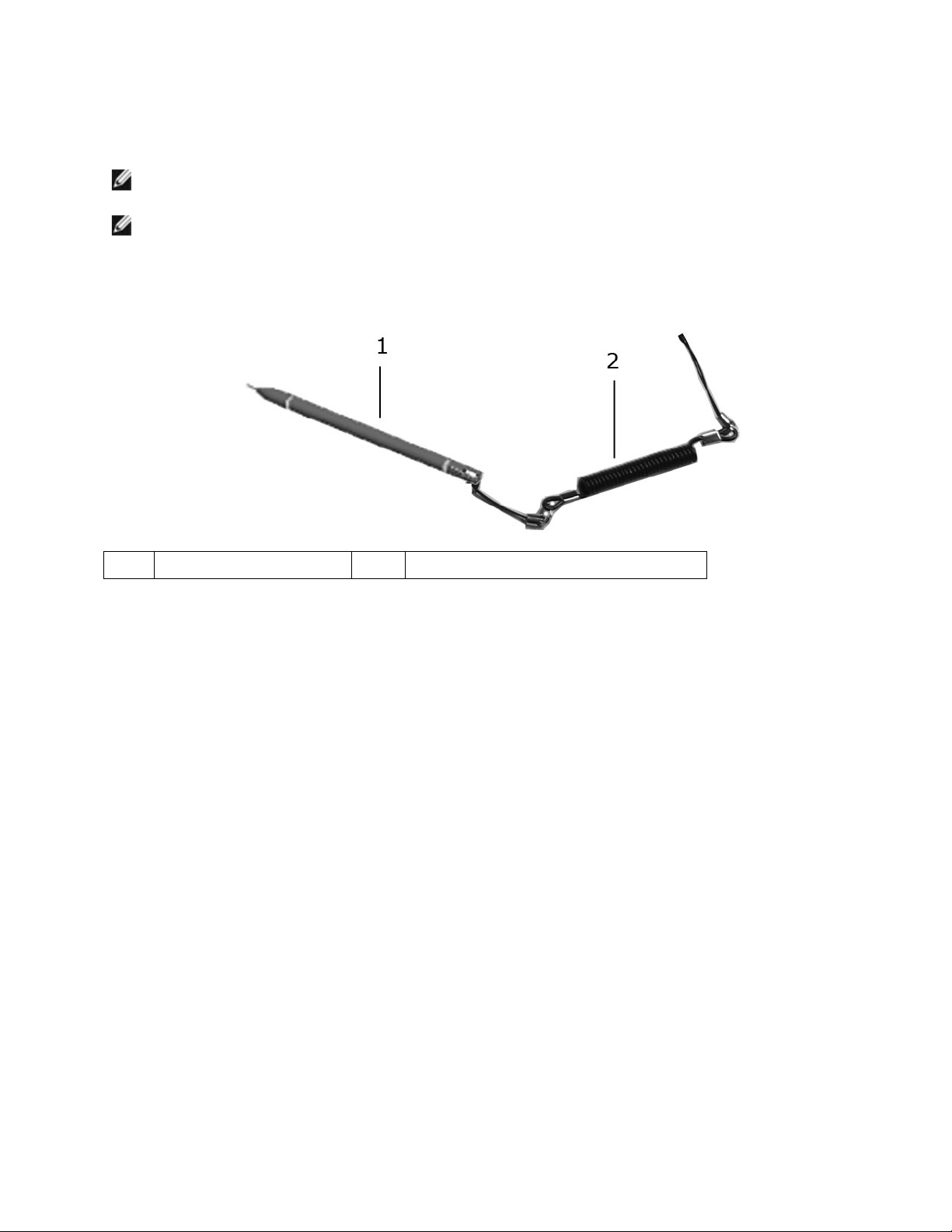
4.2 Replacing the Stylus
1
Stylus
2
Stylus tether (with loops on each end)
To replace the stylus:
1. Remove the tether and stylus from the stylus clip:
a. At the stylus clip, loosen the looped end of the tether.
b. Pull the stylus and tether through the loop until the tether is free from the stylus clip.
2. Remove the stylus from the tether:
a. At the stylus, loosen the looped end of the tether.
b. Pull the stylus and tether through the loop until the stylus is free from the tether.
3. Install the new stylus:
a. Place one of the looped ends of the tether through the hole in the end of the new
stylus and then place the free end of the tether through the loop.
b. Pull the remainder of the tether through the loop until tight.
c. Your new stylus is now attached to the tether.
4. Attach the stylus and tether to the stylus clip:
a. Place the free end of the tether through the stylus clip.
b. Pull the stylus and tether through the loop until tight.
5 Handle
The XFR D630 is equipped with a factory installed handle. This section provides instructions for
removing and installing the handle if replacement is required.
Page 20
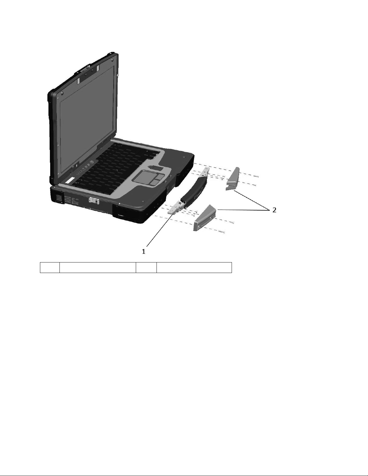
DellTM XFR D630 Fully Rugged Notebook Service Manual
Page 20 of 106
Revision A01
1
Main handle assembly
2
Handle cover (2)
5.1 Removing the Handle
1. Remove the 4 screws (2 on each handle cover) that secure the handle covers as shown in the
figure above.
2. Remove the 6 screws (3 on each side) on the top of the handle assembly that secure the
handle to the handle brackets.
3. Remove the 6 screws (3 on each side) that secure the main handle assembly.
5.2 Installing the Handle
1. Align the main handle assembly with the mounting holes in the front plate of the XFR D630 as
shown in the figure above.
2. Secure the main handle assembly to the XFR D630 using the 6 screws provided.
3. Install the 6 screws (3 on each side) on the top of the handle assembly that secure the handle
to the handle brackets.
Page 21
DellTM XFR D630 Fully Rugged Notebook Service Manual
Page 21 of 106
Revision A01
4. Align each of the handle covers over the main handle assembly ends as shown.
5. If your XFR D630 is equipped with the optional Touch Screen, please refer to
97H
Replacing the
Stylus Clip
for instructions regarding installing the stylus clip onto one side of the handle
assembly.
6. Secure the handle covers over the main handle assembly and to the XFR D630 with the 4
screws provided (2 on each side).
6 Port Covers
The XFR D630 utilizes port covers to secure and protect the connectors and devices of the notebook.
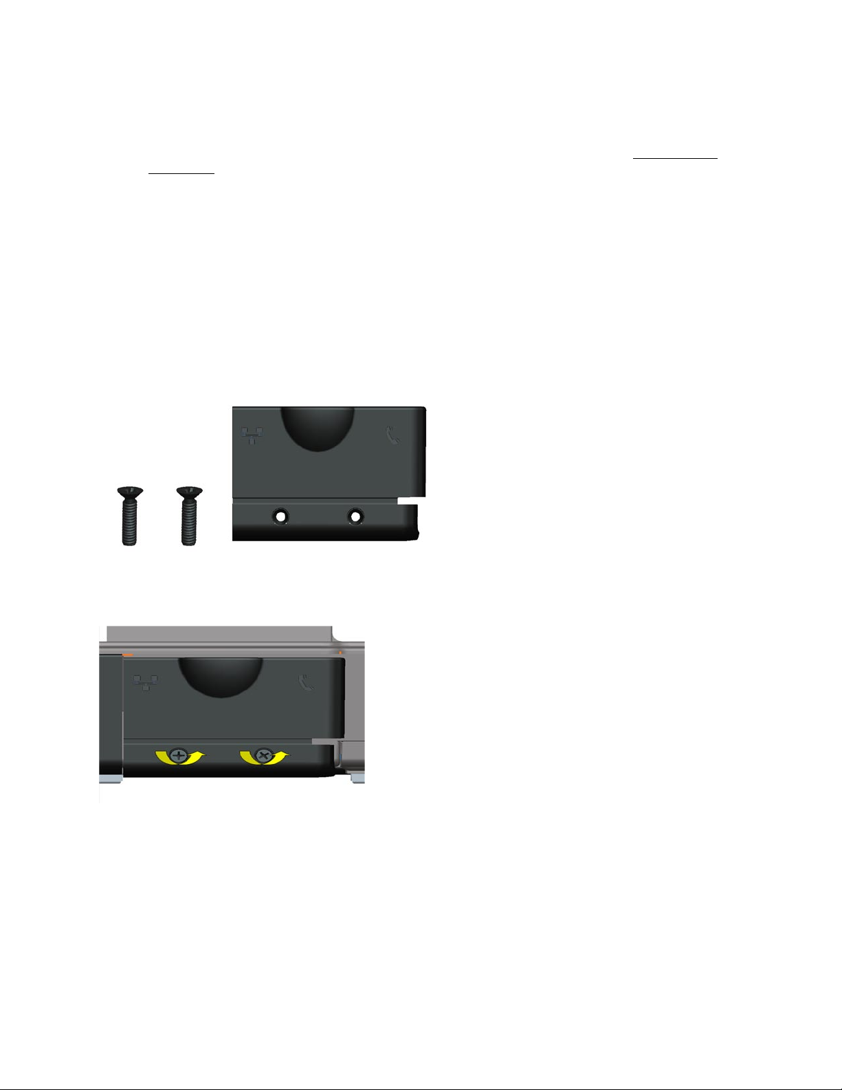
6.1 Comms Door
The Comms Door is located on the notebook’s rear panel and protects the RJ-45 and RJ-11
connectors.
6.1.1 Removing the Comms Door
1. Remove the 2 screws that secure the Comms Door.
2. Remove the Comms Door from the notebook.
Page 22
DellTM XFR D630 Fully Rugged Notebook Service Manual
Page 22 of 106
Revision A01
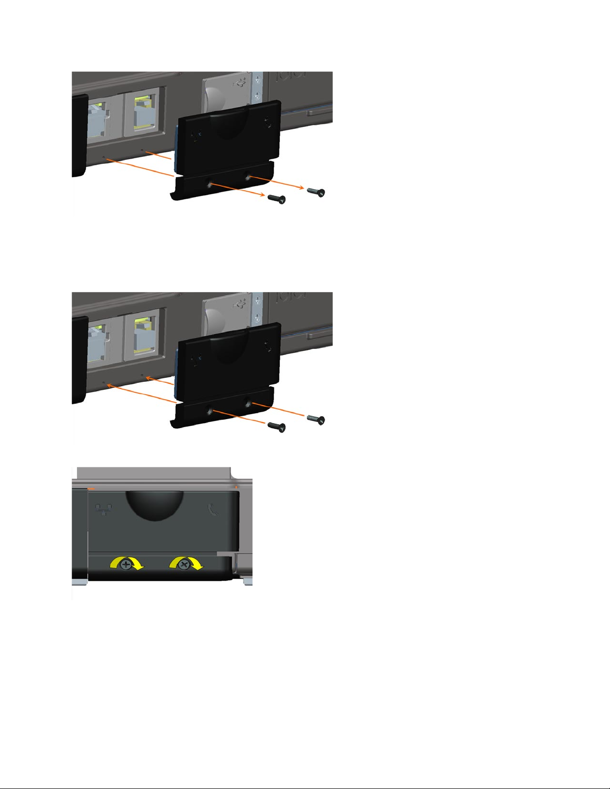
6.1.2 Installing the Comms Door
1. Align the Comms Door with the Comms Door mounting holes on the notebook.
2. Use the 2 screws to secure the Comms Door to the notebook.
6.2 Docking Door
The Docking Door is located on the bottom of the notebook, and protects the docking connector.
6.2.1 Removing the Docking Door
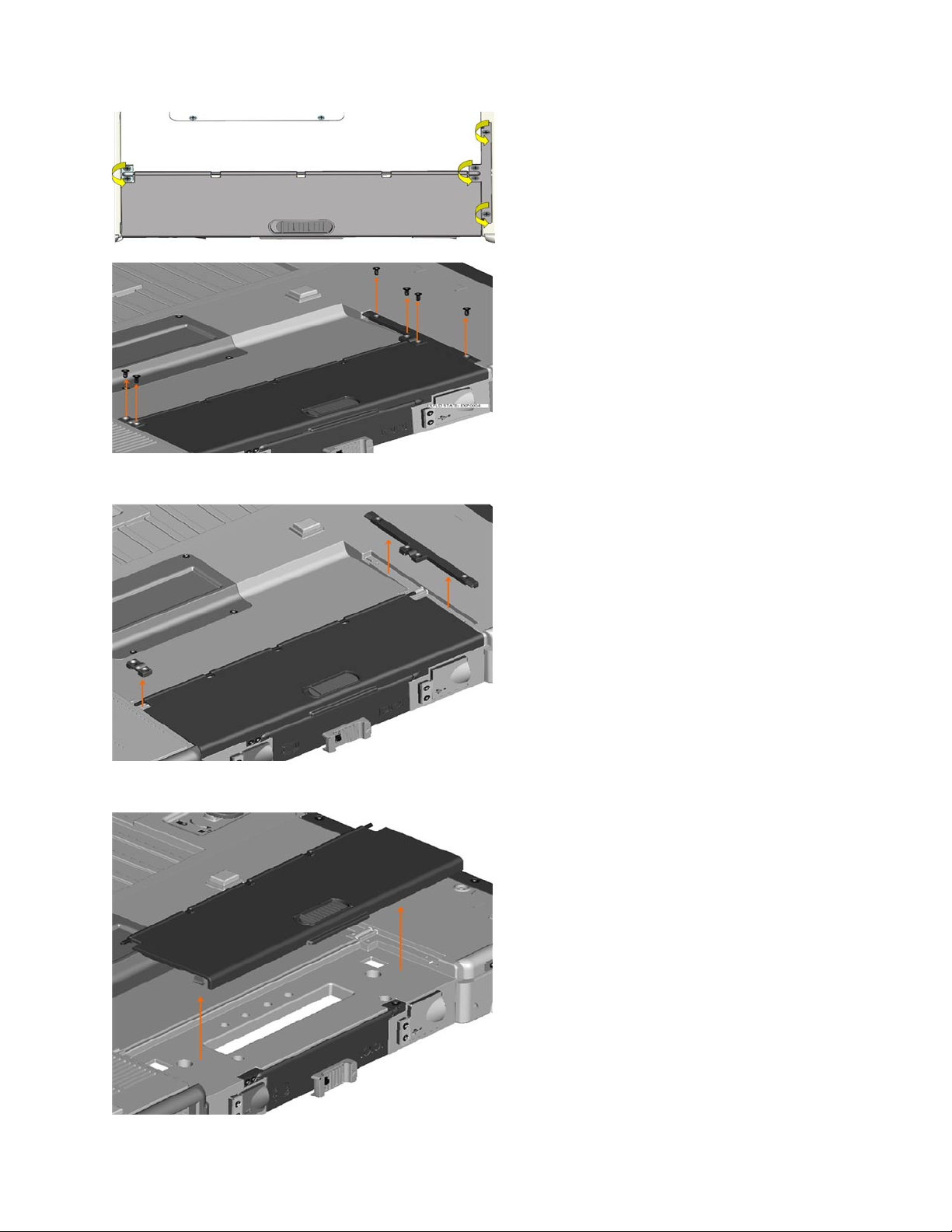
1. Remove the 6 screws that secure the Docking Door to the notebook.
Page 23
DellTM XFR D630 Fully Rugged Notebook Service Manual
Page 23 of 106
Revision A01
2. Remove the 2 brackets that secure the Docking Door.
3. Lift the Docking Door away from the notebook.
Page 24
DellTM XFR D630 Fully Rugged Notebook Service Manual
Page 24 of 106
Revision A01
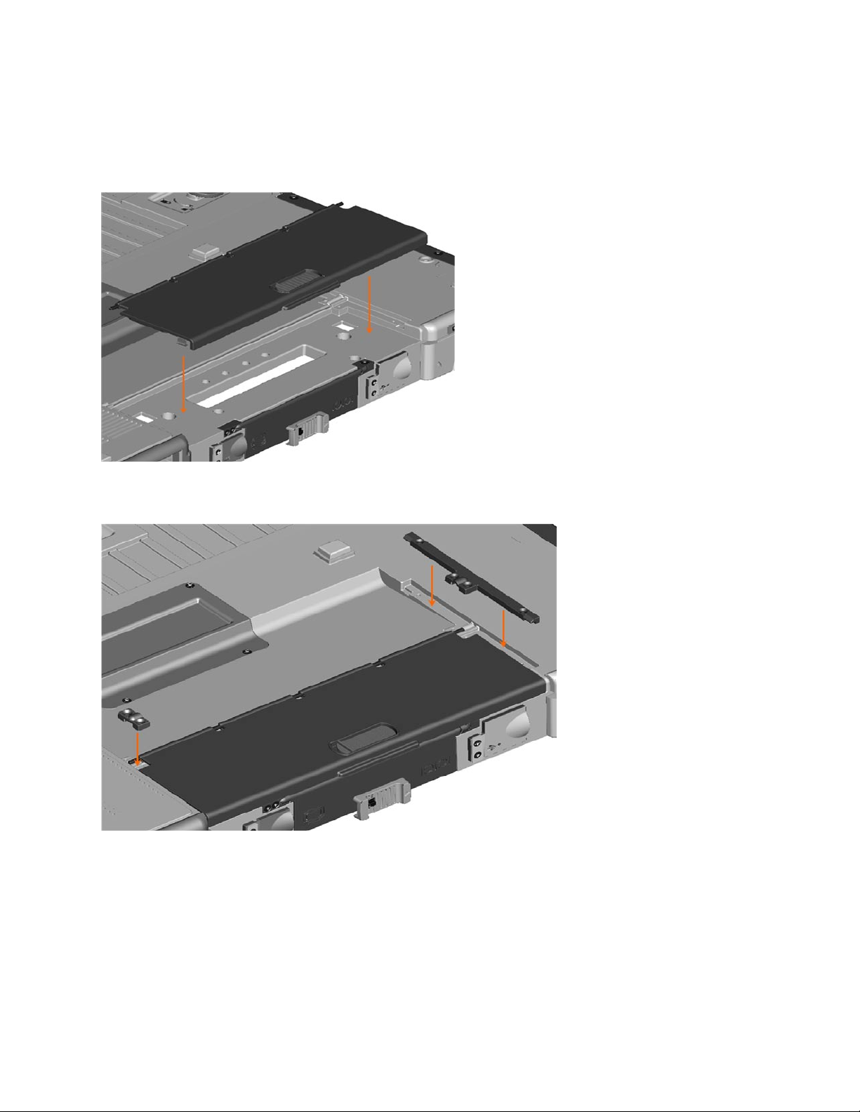
6.2.2 Installing the Docking Door
1. Place the Docking Door onto the notebook aligning it with the 6 mounting holes.
2. Place the two mounting brackets onto the docking door (see figure below).
Page 25
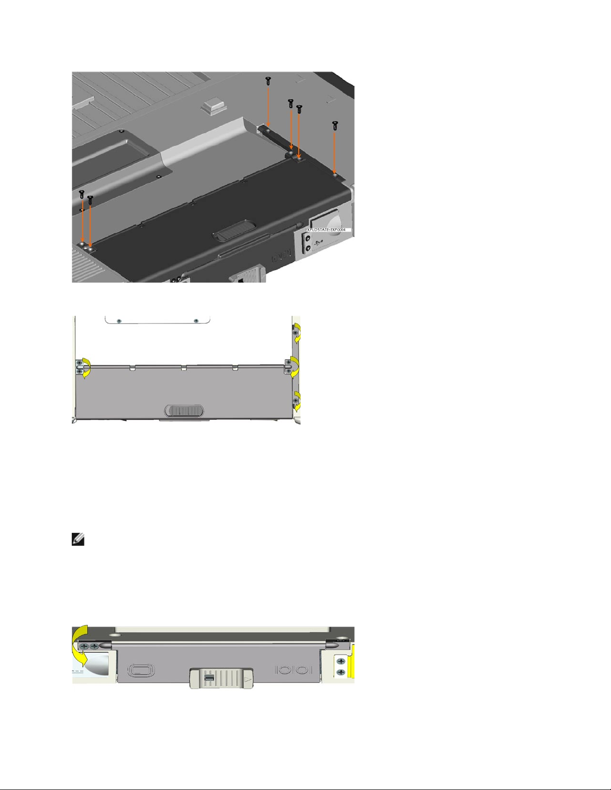
DellTM XFR D630 Fully Rugged Notebook Service Manual
Page 25 of 106
Revision A01
3. Secure the docking door with the 6 screws provided.
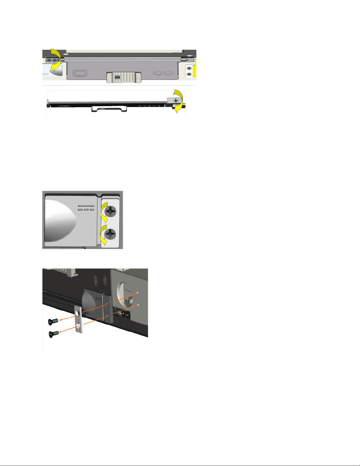
6.3 VGA Door
The VGA Door is located on the rear panel of the notebook, and protects the serial and video
connectors.
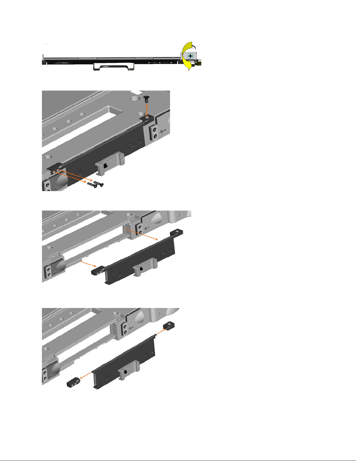
6.3.1 Removing the VGA Door
NOTE: The VGA Door is secured by 3 screws. To access all the screws the notebook must be
turned over. When facing the VGA Door, the right screw is accessed from the top, and the 2 left
screws are accessed from the front.
1. Turn the notebook top side down, to access the VGA Door on the rear panel of the notebook.
2. Remove the 3 screws that secure the VGA Door (one screw on the top right, the other 2 on
the front left).
Page 26
DellTM XFR D630 Fully Rugged Notebook Service Manual
Page 26 of 106
Revision A01
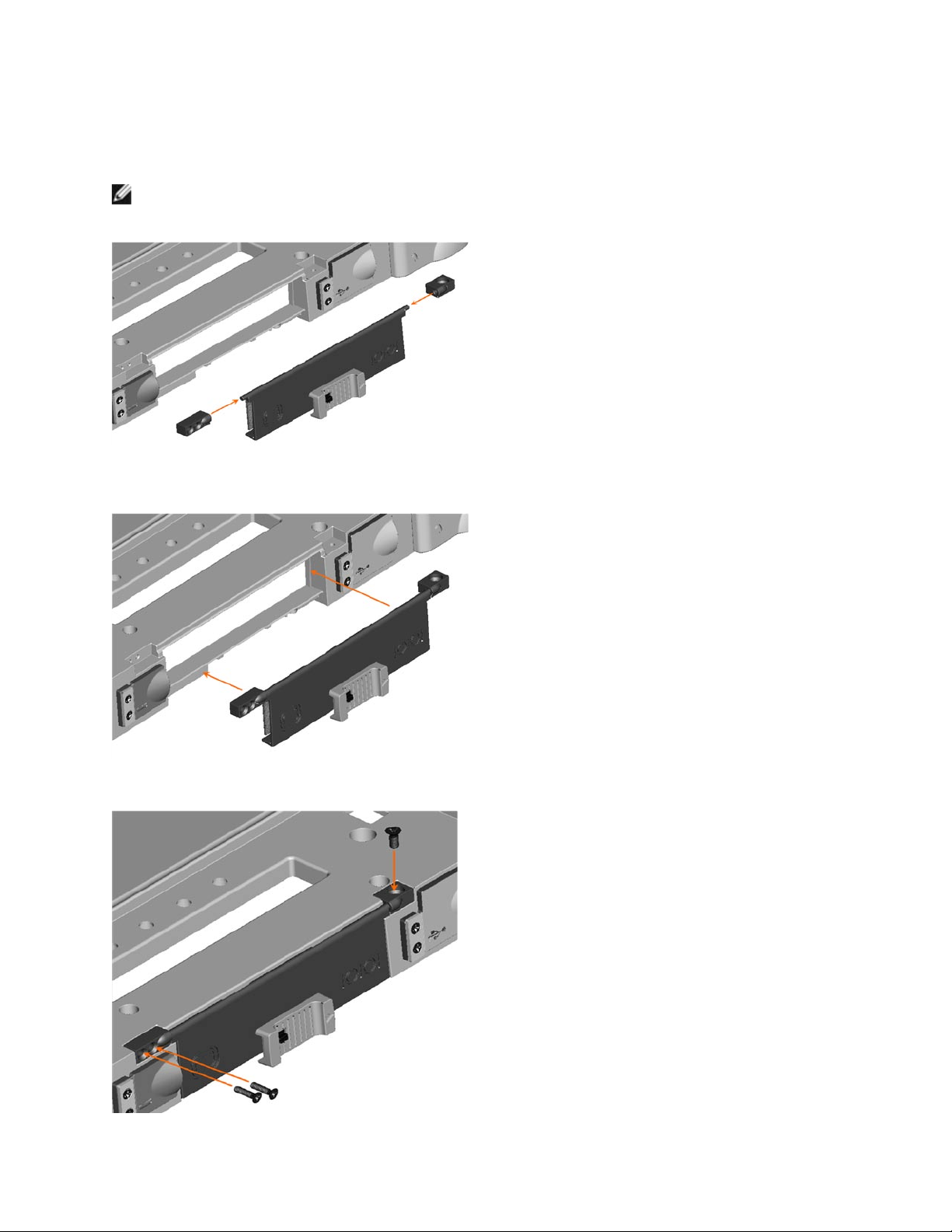
3. Remove the VGA Door from the notebook.
4. Remove the 2 screw mounts from the VGA Door hinge and set aside for later use.
Page 27
DellTM XFR D630 Fully Rugged Notebook Service Manual
Page 27 of 106
Revision A01
6.3.2 Installing the VGA Door
1. Place the 2 screw mounts on the VGA Door hinge.
NOTE: Be careful to ensure that the single screw mount is placed on the right side of the hinge,
while the 2 screw mount is placed on the left side of the hinge.
2. Place the VGA Door and screw mounts onto the notebook and align with the mounting holes
provided.
3. Secure the VGA Door to the notebook, using the 3 screws provided.
Page 28
DellTM XFR D630 Fully Rugged Notebook Service Manual
Page 28 of 106
Revision A01
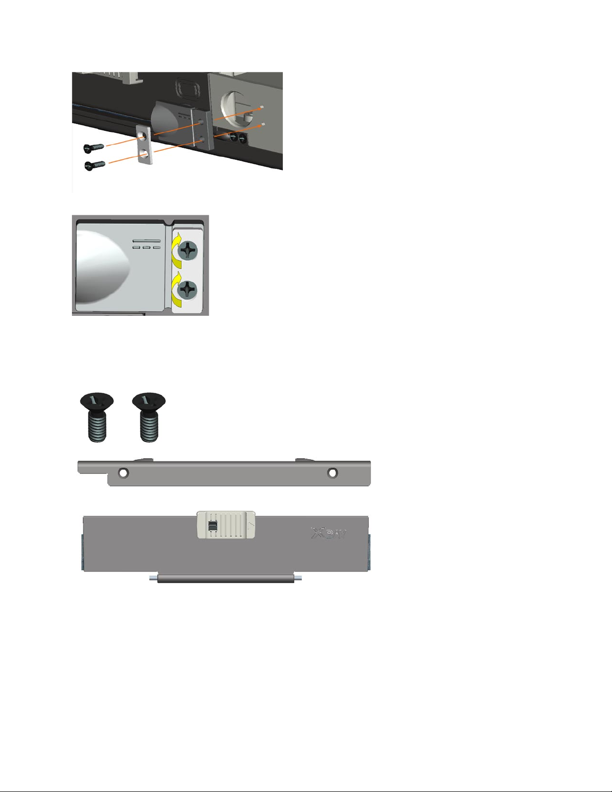
6.4 Power Door
The Power Door is located on the rear panel of the notebook, and protects the notebook’s power
connector.
6.4.1 Removing the Power Door
1. Remove the 2 screws that secure the Power Door to the notebook.
2. Remove the screw plate and the Power Door from the notebook.
6.4.2 Installing the Power Door
1. Align the Power Door and the screw plate with the screw holes provided on the rear panel for
the Power Door.
Page 29
DellTM XFR D630 Fully Rugged Notebook Service Manual
Page 29 of 106
Revision A01
2. Use the 2 screws provided to secure the screw plate and Power Door to the notebook.
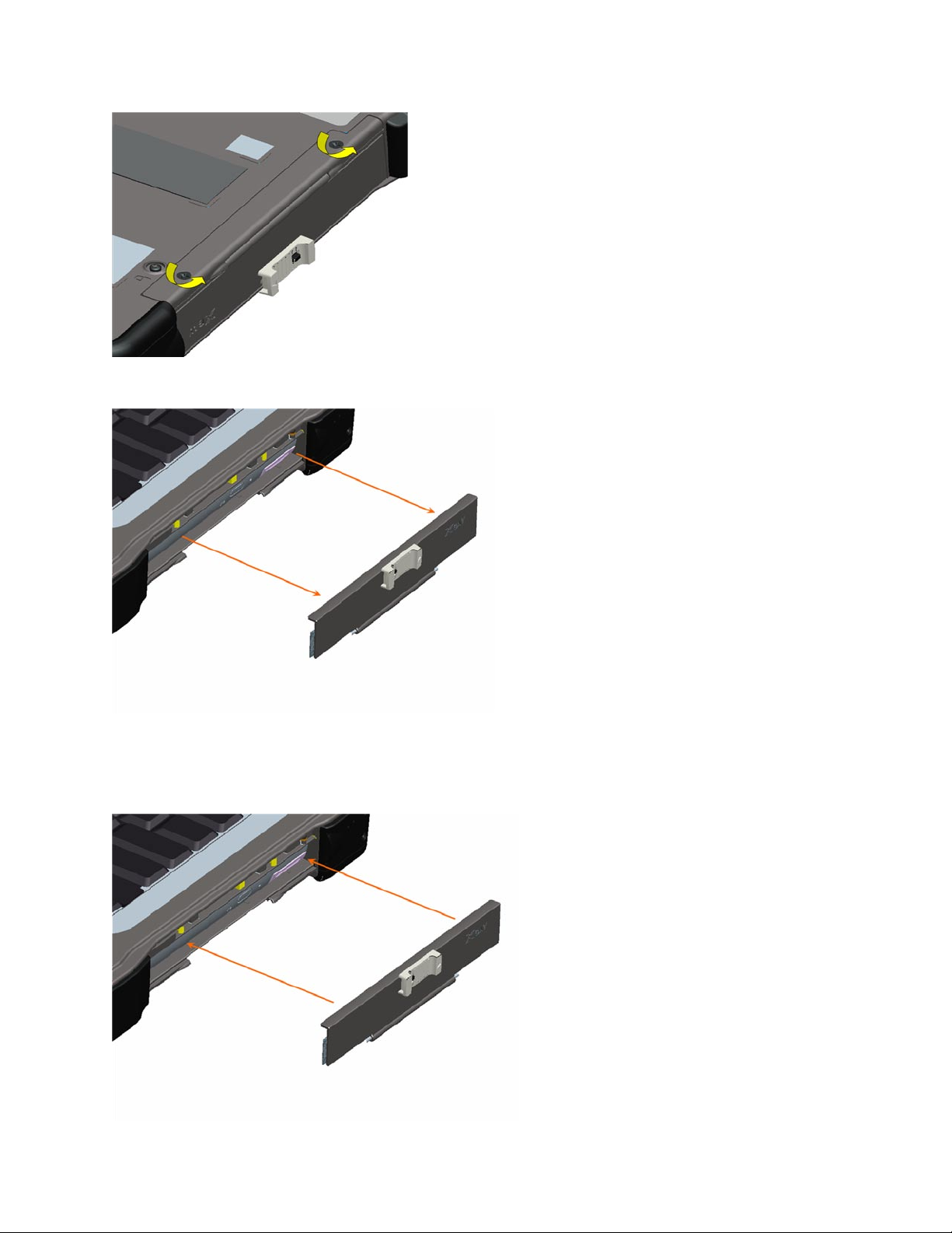
6.5 XBay Door
6.5.1 Removing the XBay Door
The XBay Door is located on the notebook’s right side, and protects the notebook’s optical drive.
1. Turn the notebook top side down, and remove the 2 screws that secure the XBay Door.
Page 30
DellTM XFR D630 Fully Rugged Notebook Service Manual
Page 30 of 106
Revision A01
2. Remove the XBay Door from the notebook.
6.5.2 Installing the XBay Door
1. Place the XBay Door onto the notebook, aligning it with the 2 screw mount holes.
Page 31

DellTM XFR D630 Fully Rugged Notebook Service Manual
Page 31 of 106
Revision A01
2. Using the 2 screws provided, secure the XBay Door to the notebook.
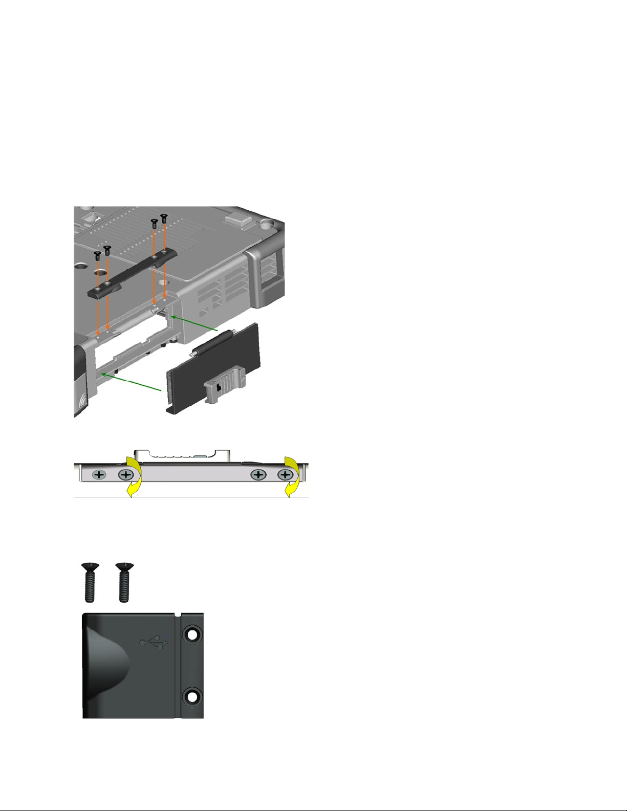
6.6 Audio Ports/WiFi Door
The Audio Ports/WiFi Door is located on the left side of the notebook, and protects the notebook’s
audio connectors, smart card slot, 1394 connector, and wireless switch.
To access the Audio Ports/WiFi Door for service, turn the notebook bottom side up.
6.6.1 Removing the Audio Ports/WiFi Door
1. Remove the 4 screws that secure the Audot Ports/WiFi Door’s hinge retaining bar.
2. Lift the hinge retaining bar away from the notebook, which then allows the door to be
removed from the notebook.
Page 32
DellTM XFR D630 Fully Rugged Notebook Service Manual
Page 32 of 106
Revision A01
6.6.2 Installing the Audio Ports/WiFi Door
1. Place the Audio Ports/Wifi Door’s onto the notebook, aligning the door hinge into the slot on
the notebook.
2. Place the hinge retaining bar over the hinge.
3. Align the holes in the retaining bar with the holes in the notebook.
4. Use the 4 screws to secure the hinge retaining bar.
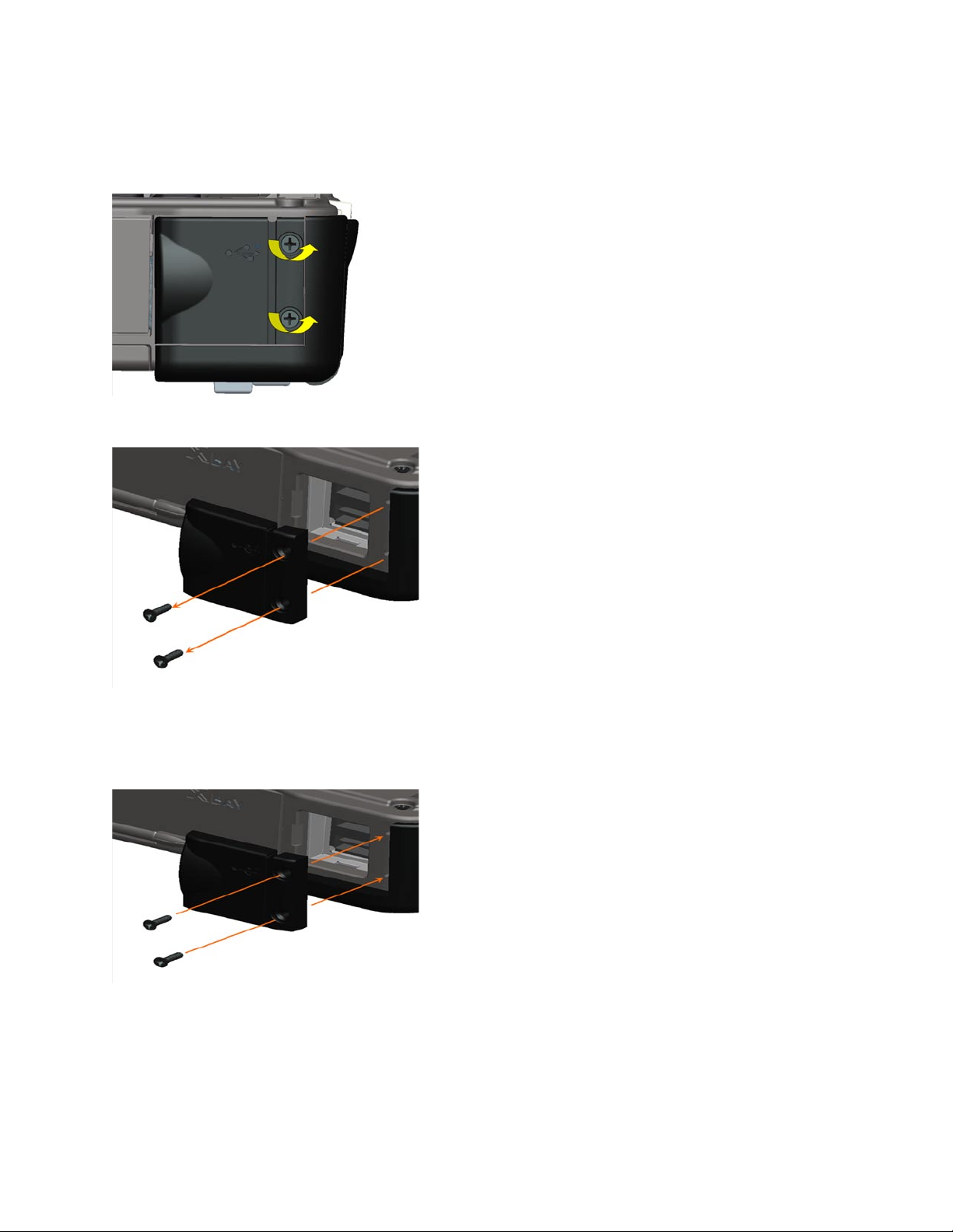
6.7 USB Side Door
The USB Side Door is located on the notebook’s right side, and protects 2 USB connectors.
Page 33
DellTM XFR D630 Fully Rugged Notebook Service Manual
Page 33 of 106
Revision A01
6.7.1 Removing the USB Side Door
1. Remove the 2 screws that secure the USB Side Door to the notebook.
2. Remove the USB Side Door from the notebook.
6.7.2 Installing the USB Side Door
1. Place the USB Side Door onto the notebook, aligning it with the 2 screw mount holes.
2. Install the 2 screws to secure the USB Side Door to the notebook.
Page 34
DellTM XFR D630 Fully Rugged Notebook Service Manual
Page 34 of 106
Revision A01
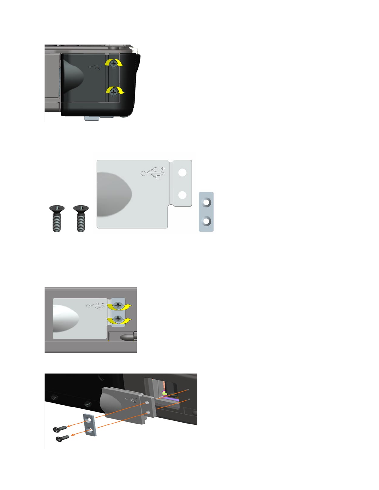
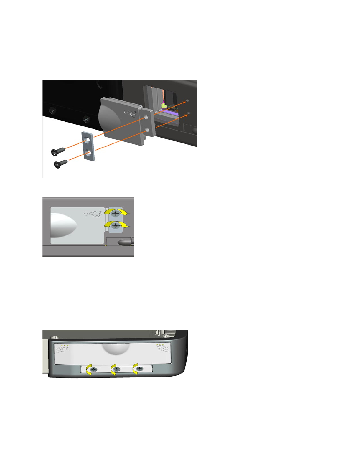
6.8 USB Rear Door
The USB Rear Door is located on the notebook’s rear panel, and protects 2 USB connectors.
6.8.1 Removing USB Rear Door
1. Remove the 2 screws that secure the USB Rear Door to the chassis. Also remove the gasket
which is positioned between the screws and the door.
2. Remove the USB Rear Door from the notebook.
Page 35
DellTM XFR D630 Fully Rugged Notebook Service Manual
Page 35 of 106
Revision A01
6.8.2 Installing USB Rear Door
1. Position the USB Rear Door onto the notebook, aligning it with the 2 screw mount holes on the
notebook. Then align the gasket with the screw holes on the USB Rear Door.
2. Using the 2 screws provided, secure the USB Rear Door and the gasket to the notebook.
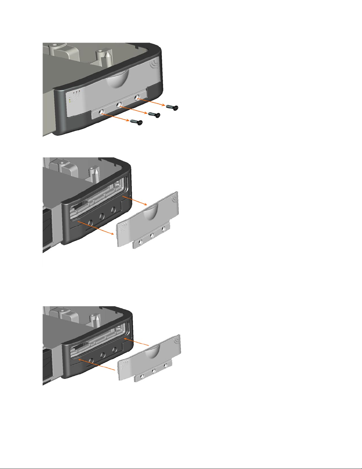
6.9 PC Card Slot Door
The PC Card Slot Door is located on the notebook’s left side, and protects the notebook’s PC
Card/ExpressCard Slot.
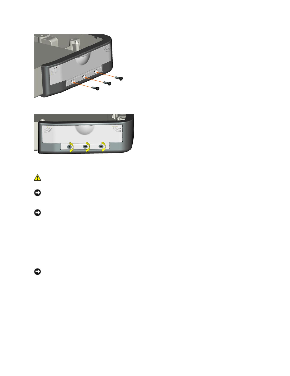
6.9.1 Removing the PC Card Slot Door
1. Remove the 3 screws that secure the PC Card Slot Door to the notebook.
Page 36
DellTM XFR D630 Fully Rugged Notebook Service Manual
Page 36 of 106
Revision A01
2. Remove the PC Card Slot Door from the notebook.
6.9.2 Installing the PC Card Slot Door
1. Align the PC Card Slot Door with the 3 screw mount holes on the notebook.
2. Using the 3 screws provided, secure the PC Card Slot Door to the notebook.
Page 37
DellTM XFR D630 Fully Rugged Notebook Service Manual
Page 37 of 106
Revision A01
7 Hinge Cover
CAUTION: Before working inside your computer, follow the safety instructions in the
XFR D630 Product Information Guide and in the XFR D630 User’s Guide.
NOTICE: To avoid electrostatic discharge, ground yourself by using a wrist grounding strap or by
periodically touching an unpainted metal surface (such as a connector on the back of the
computer).
NOTICE: The hinge cover is fragile and can be damaged if extreme force is used. Be careful
when removing the hinge cover.
7.1 Removing the Hinge Cover
1. Follow the procedures in
98H
Before You Begin
.
2. Turn the computer top-side up, and then open the display all the way (160 degrees).
NOTICE: To avoid damaging the hinge cover, do not lift the cover on both sides simultaneously.
Removing the hinge cover in a different way than described may cause the plastic to break.
Page 38
DellTM XFR D630 Fully Rugged Notebook Service Manual
Page 38 of 106
Revision A01
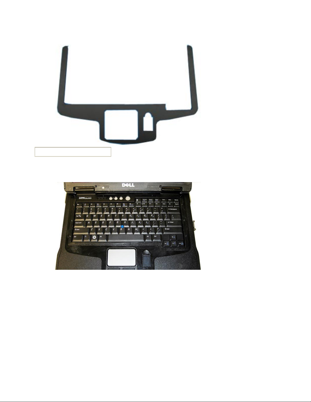
Keyboard/palm rest overlay
3. Remove keyboard/palm rest overlay first. Start in top corners next to each hinge to remove
the overlay. The overlay peels off.
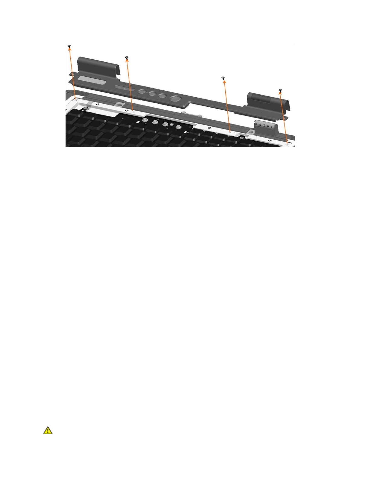
4. Remove the 4 M2 x 5-mm screws that secure the hinge cover to the base. See image below.
Page 39
DellTM XFR D630 Fully Rugged Notebook Service Manual
Page 39 of 106
Revision A01
5. Starting on the right side of the notebook, use a plastic scribe inserted in the hinge area to pry
up the hinge cover. Lift the right side of the hinge cover away from the notebook. Then go to
the left side, and similarly lift the left side of the hinge cover.
6. Remove the hinge cover. Lay the hinge cover aside.
7.2 Installing the Hinge Cover
Before installing the hinge cover, ensure that all cables are routed correctly. Improper routing of the
cables can cause damage to the cables.
1. To replace the hinge cover, insert the left edge of the cover into place and place the hinge
cover over the hinges.
2. Ensure that the hinge cover edges line up with those on the palm rest.
3. Install the 4 screws to secure the hinge cover to the base.
4. Install the new keyboard/palm rest overlay.
a. Remove the backing from the new keyboard/palm rest overlay.
b. Start applying the overlay around the touchpad area to align the overlay.
c. Press evenly and firmly as the overlay is applied.
d. The top of the overlay will cover the hinge cover screws on each side of the hinge cover.
8 Keyboards
The XFR can be equipped with either the standard keyboard or the optional rugged, backlit keyboard.
This section provides instructions for the removal and installation of both keyboards.
8.1 Standard Keyboard
8.1.1 Removing the Standard Keyboard
CAUTION: Before working inside your computer, follow the safety instructions in the
Page 40
DellTM XFR D630 Fully Rugged Notebook Service Manual
Page 40 of 106
Revision A01
XFR D630 Product Information Guide and in the XFR D630 User’s Guide.
NOTICE: To avoid electrostatic discharge, ground yourself by using a wrist grounding strap or by
periodically touching an unpainted metal surface (such as a connector on the back of the
computer).
1. Follow the instructions in
99H
Before You Begin
.
2. Turn the computer right-side up and open it.
3. Remove the hinge cover (see
100H
Removing the Hinge Cover
).
NOTICE: Do not remove the keyboard from the keyboard tray! You are removing the entire
tray, not just the keyboard. The normal keyboard screws above the keyboard attach the
keyboard to the tray. See next step for keyboard tray removal.
4. Loosen the fifteen keyboard tray captive screws.
1
Keyboard tray captive screw (15)
NOTE: Lift the keyboard carefully in step 5 to ensure that you do not pull on the keyboard cable.
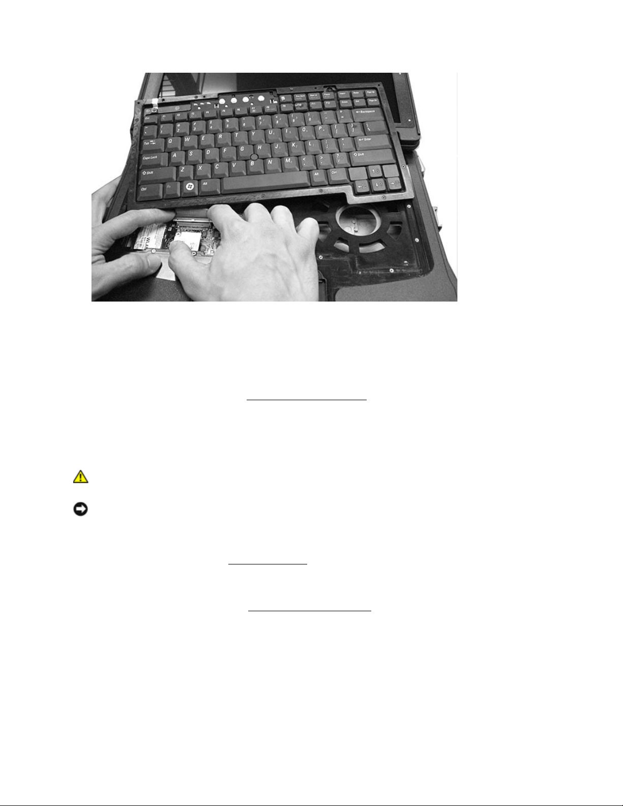
5. Lift the keyboard tray slightly.
6. Pull up on the pull-tab to disconnect the keyboard cable connector from the keyboard
connector on the system board.
1
Page 41
DellTM XFR D630 Fully Rugged Notebook Service Manual
Page 41 of 106
Revision A01
8.1.2 Installing the Standard Keyboard
1. Attach the keyboard cable to the motherboard.
2. Lay the keyboard tray in position and tighten down the 15 captive screws.
3. Replace the hinge cover (see
101H
Installing the Hinge Cover
).
8.2 Rugged Keyboard
8.2.1 Removing the Rugged Keyboard
CAUTION: Before working inside your computer, follow the safety instructions in the
XFR D630 Product Information Guide and in the XFR D630 User’s Guide.
NOTICE: To avoid electrostatic discharge, ground yourself by using a wrist grounding strap or by
periodically touching an unpainted metal surface (such as a connector on the back of the
computer).
1. Follow the instructions in
102H
Before You Begin
.
2. Turn the computer right-side up and open it.
3. Remove the hinge cover (see
103H
Removing the Hinge Cover
).
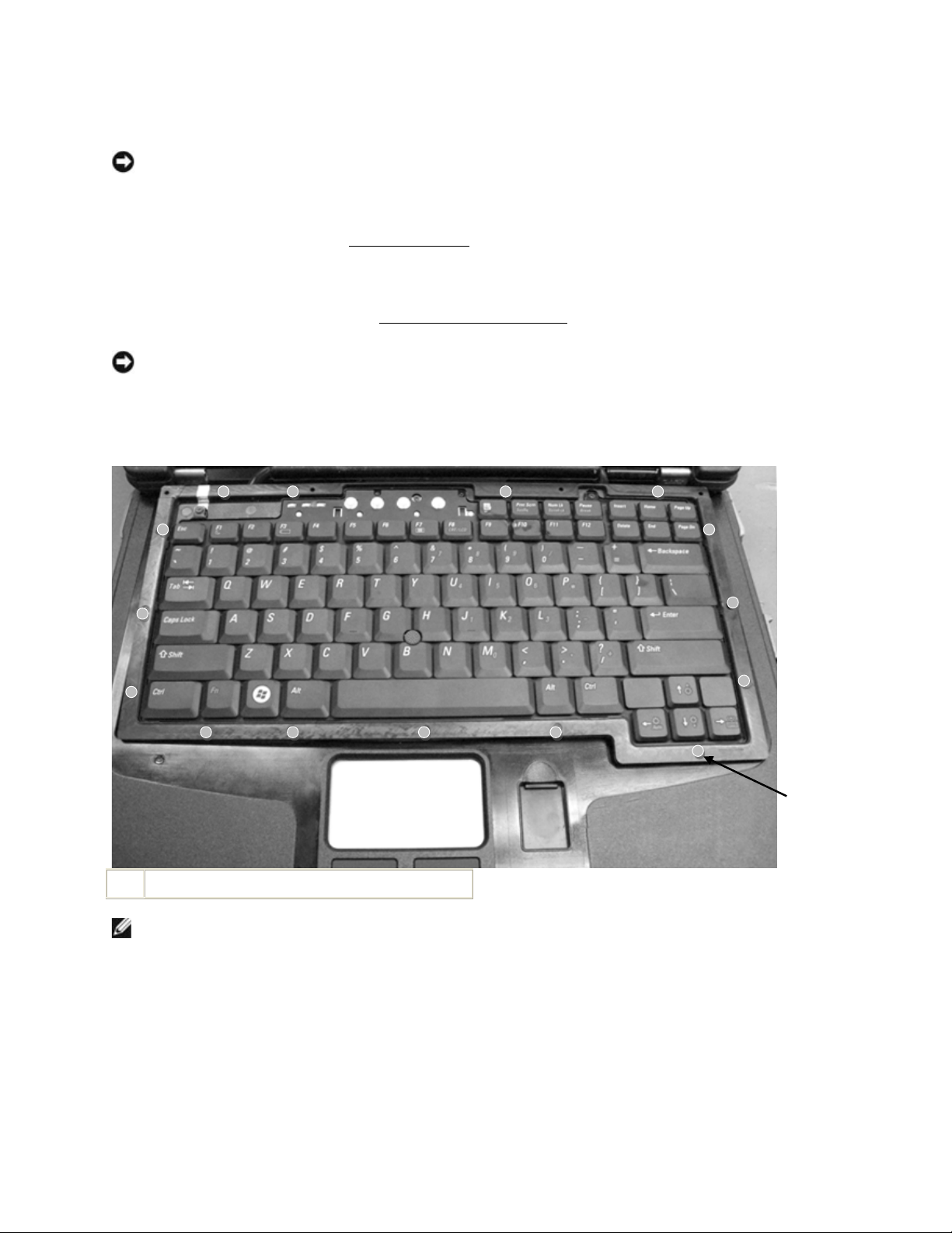
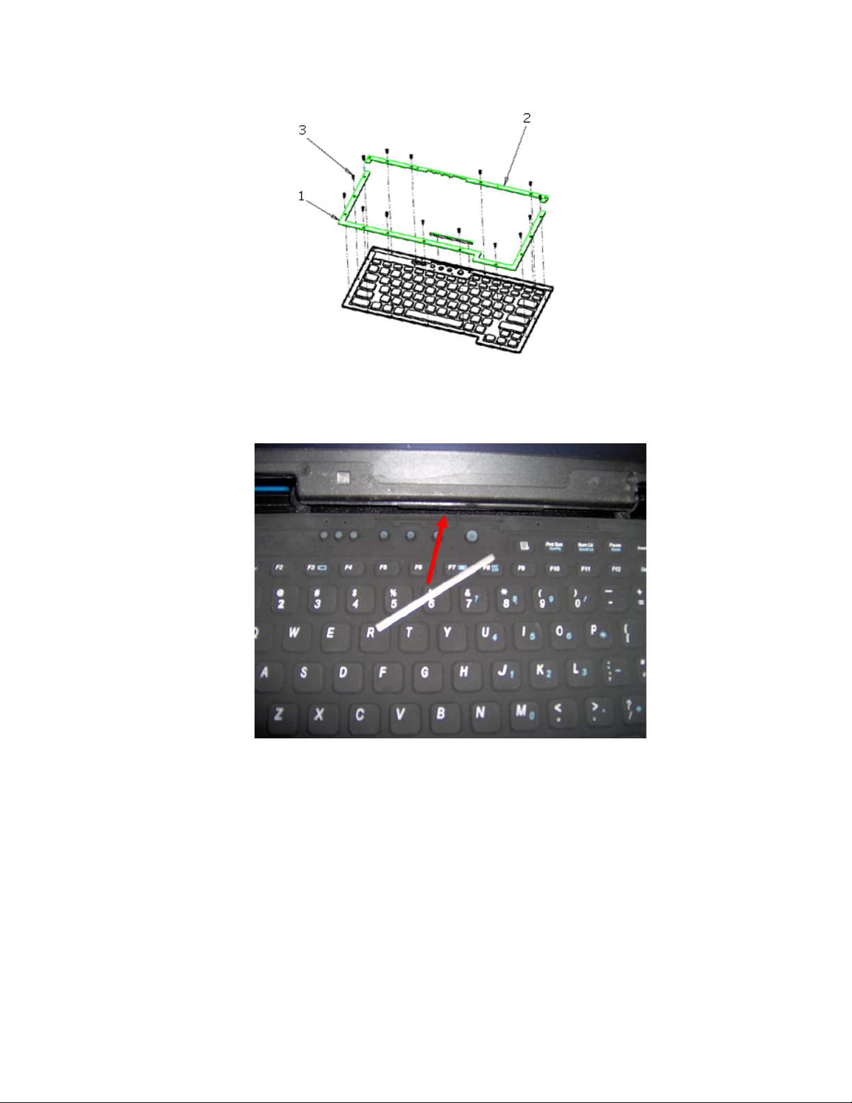
4. Remove the 15 M2x6 captive screws (item 3 in image below) that secure the top and bottom
metal brackets (items 1 and 2 in image below) around the keyboard. Remove the top and
bottom metal brackets.
Page 42
DellTM XFR D630 Fully Rugged Notebook Service Manual
Page 42 of 106
Revision A01
5. Lift up on the rubber lip around the keyboard to lift the keyboard away from the system. Be
sure to locate and remove the keyboard stiffener bar located at the top of the keyboard above
the power and audio buttons.
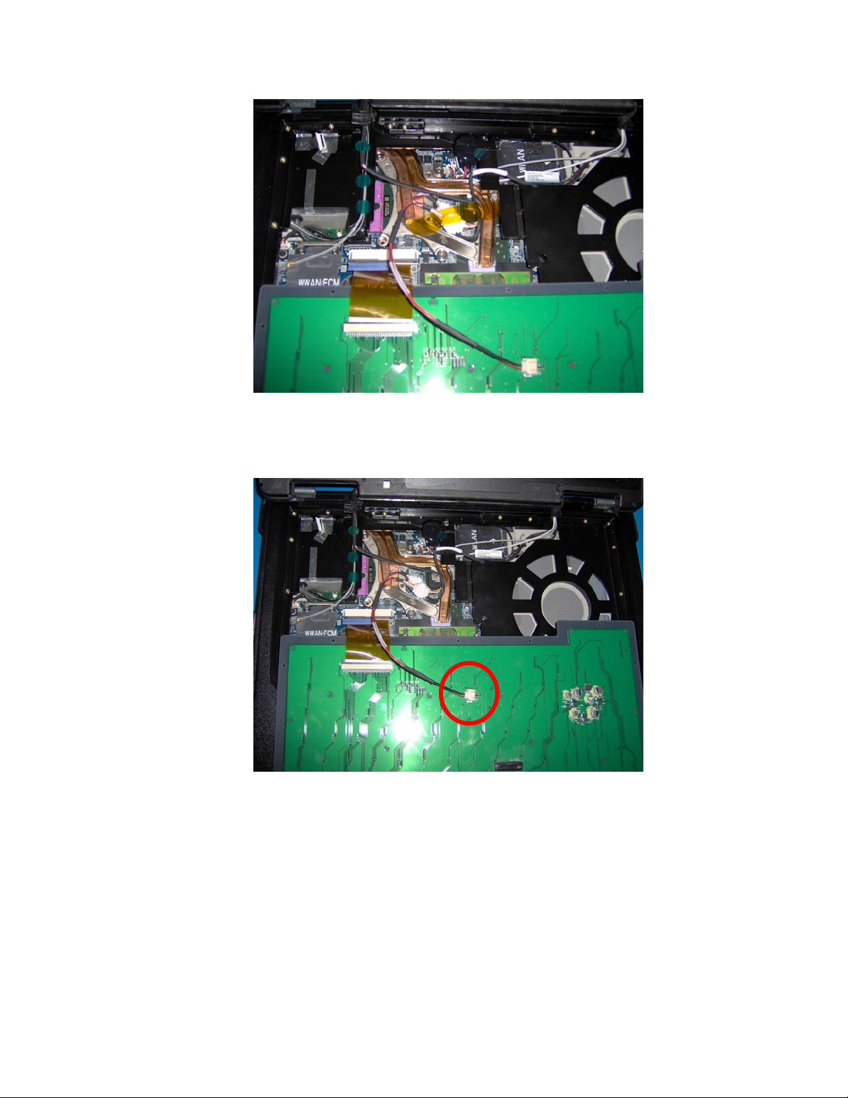
6. Rotate the keyboard towards yourself, so that the bottom of the keyboard and the keyboard
cables are viewable.
Page 43
DellTM XFR D630 Fully Rugged Notebook Service Manual
Page 43 of 106
Revision A01
7. Remove the Kapton tape that secures the spliced cable and the backlight power cable in place.
8. Disconnect the keyboard backlight power cable from the back of the keyboard.
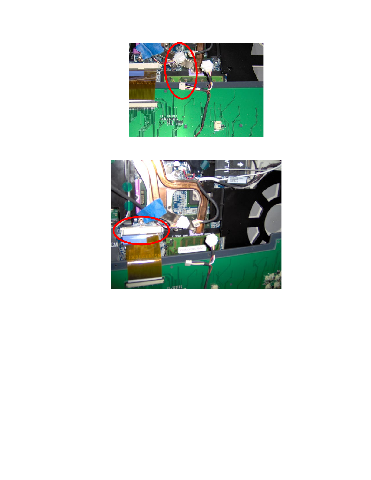
9. Disconnect the keyboard backlight cable from the touch screen splice coming from the mother
board. If this is a touch screen system, also disconnect the keyboard to backlight cable from
the touch screen splice coming from the LCD.
Page 44
DellTM XFR D630 Fully Rugged Notebook Service Manual
Page 44 of 106
Revision A01
9. Disconnect the rugged keyboard connector from the motherboard connector.
8.2.2 Installing the Rugged Keyboard
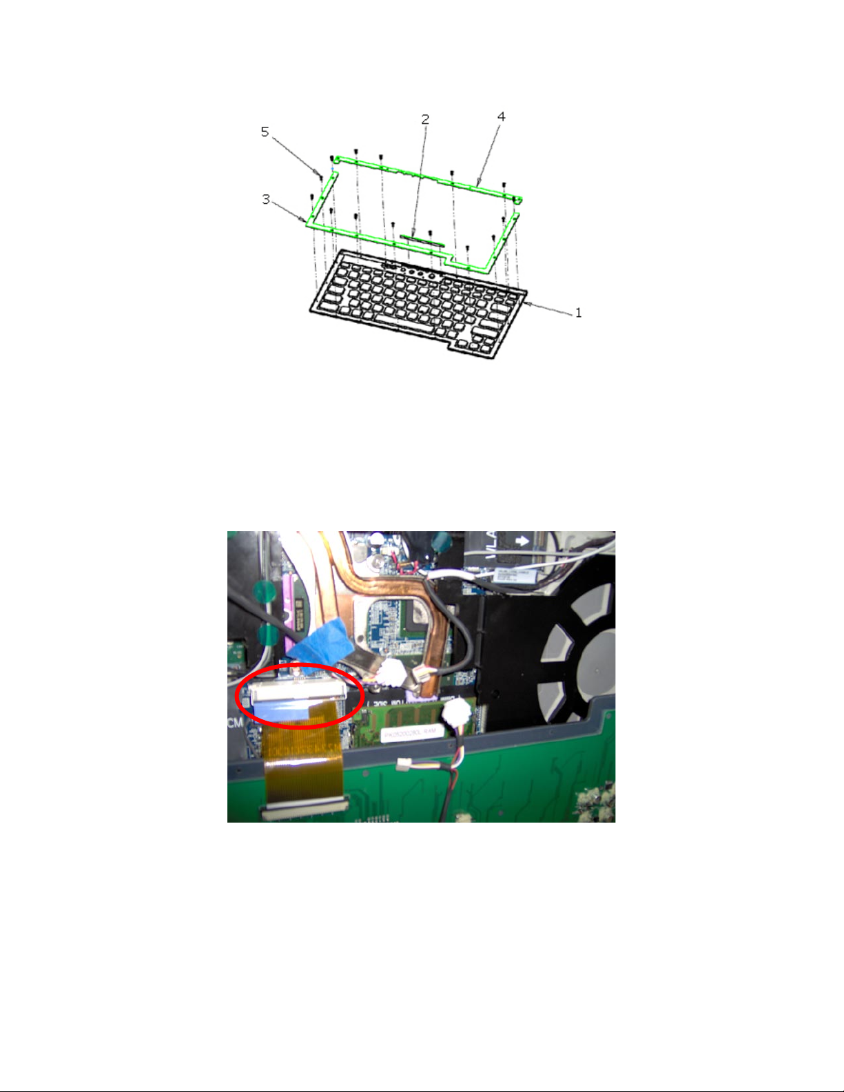
The following parts are required to assemble the rugged keyboard to the Dell XFR.
Page 45
DellTM XFR D630 Fully Rugged Notebook Service Manual
Page 45 of 106
Revision A01
1. KYBD, 87, US, ENG, RGD, XFR
2. Rubber keyboard stiffener bar
3. CLMP, SPRT, PLMST, MET, BOTTOM, XFR
4. CLMP, SPRT, PLMST, MET, TOP, XFR
5. CSK CAPTIVE SCREW M2x6 – BLACK (x15)
6. CABLE ASSY, KYBD, BACKLIGHT (not shown in image above)
Installation Steps:
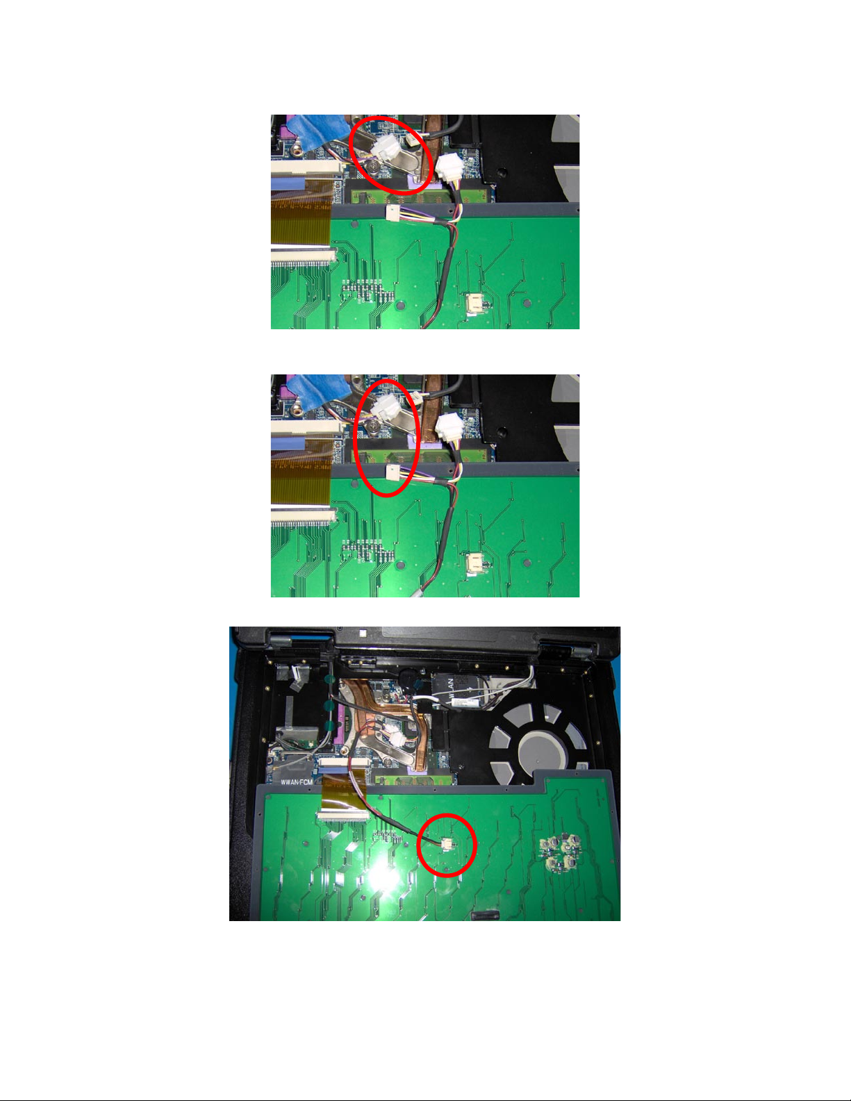
1. Connect the rugged keyboard connector to the mother board connector.
Page 46
DellTM XFR D630 Fully Rugged Notebook Service Manual
Page 46 of 106
Revision A01
2. Connect keyboard backlight cable to the touch screen splice coming from the mother board.
3. Connect keyboard to backlight cable to the touch screen splice coming from the LCD if this is a
touch screen system.
4. Connect the keyboard backlight cable to the back of the keyboard.
Page 47
DellTM XFR D630 Fully Rugged Notebook Service Manual
Page 47 of 106
Revision A01
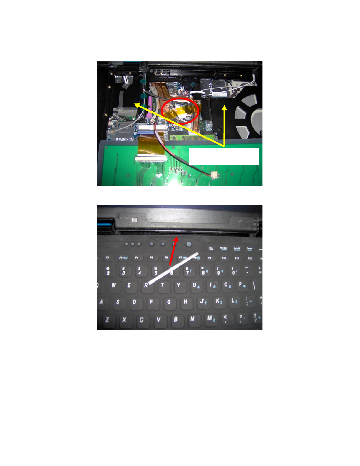
5. Place connectors from the spliced cable and the backlight power cable in the recessed area of
the thermal solution. Stack them and use a 2.5” piece of Kapton tape to hold them in place
below the level of the palmrest.
6. Assemble the keyboard stiffener bar into the slot above the power and audio buttons. Do this
before assembling the keyboard to the palmrest.
Connectors should not
stack above this level.
Page 48
DellTM XFR D630 Fully Rugged Notebook Service Manual
Page 48 of 106
Revision A01
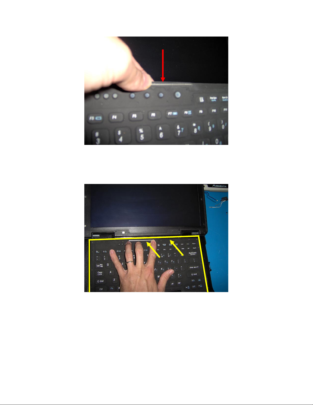
7. Assemble the keyboard onto the palmrest.
a. Apply pressure around the perimeter to ensure the keyboard lip is properly fitted
to the palmrest bucket.
b. Apply pressure on the area around the keyboard stiffener bar and near the right
hinge to ensure there is no bulging.
Page 49
DellTM XFR D630 Fully Rugged Notebook Service Manual
Page 49 of 106
Revision A01
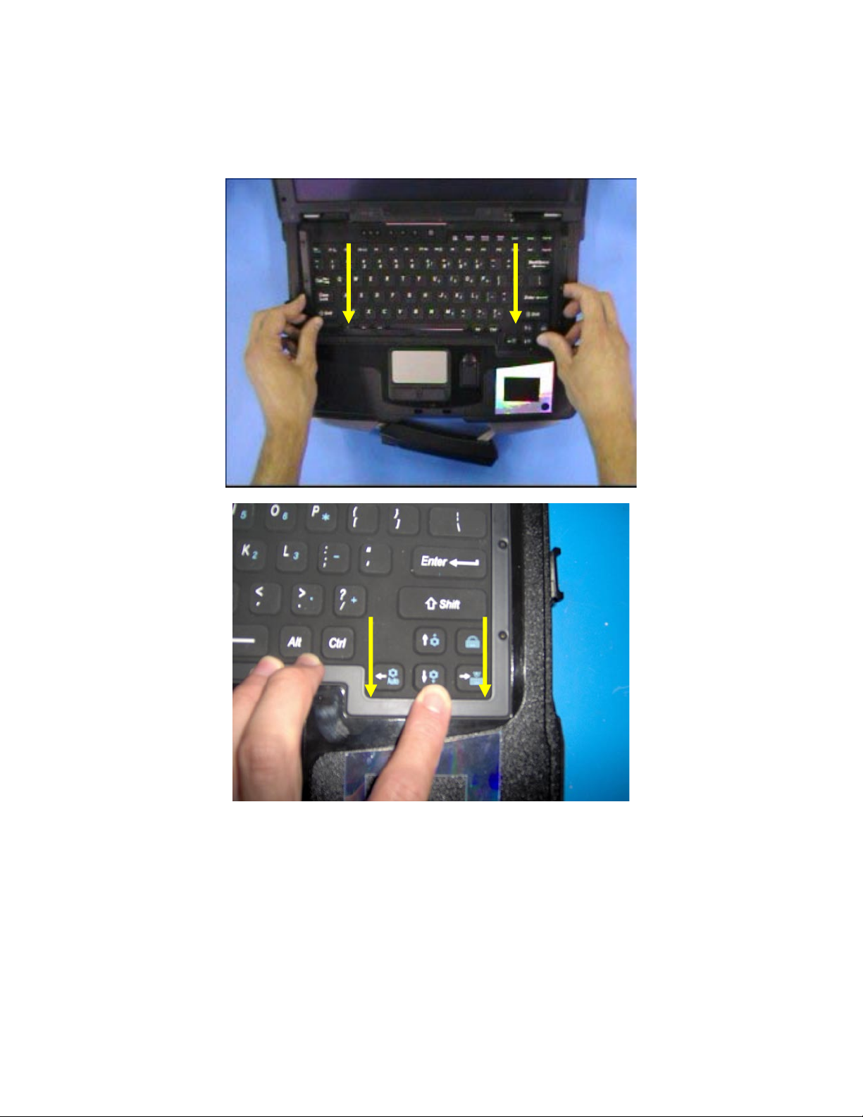
8. Assemble the bottom metal bracket paying close attention to the lower right corner. Move the
bracket in the direction shown in the image below. The bracket should fit in place, pressing
the rubber lip against the palmrest. Make sure the rubber lip looks uniform throughout the
perimeter and that it has not folded under the bracket. Any gaps will compromise the quality
of the seal.
Page 50
DellTM XFR D630 Fully Rugged Notebook Service Manual
Page 50 of 106
Revision A01
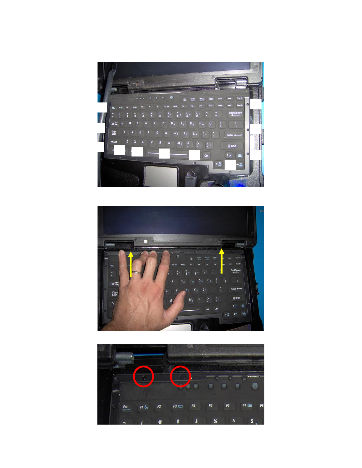
9. Fasten the 11 M2x6 screws in the order shown in the image below to secure the bottom metal
bracket. As each of the screws around the bracket are secured, ensure that the rubber lip is
not folded under the bracket.
10. Assemble the top metal bracket ensuring the rubber lip is not folded under the bracket. Move
the bracket into position in the direction shown in the image below.
11. Fasten the 2 M2x6 screws shown in the image below to the left side of the top metal bracket.
2
1
3
4
5
6
7
8
9
10
11
Page 51
DellTM XFR D630 Fully Rugged Notebook Service Manual
Page 51 of 106
Revision A01
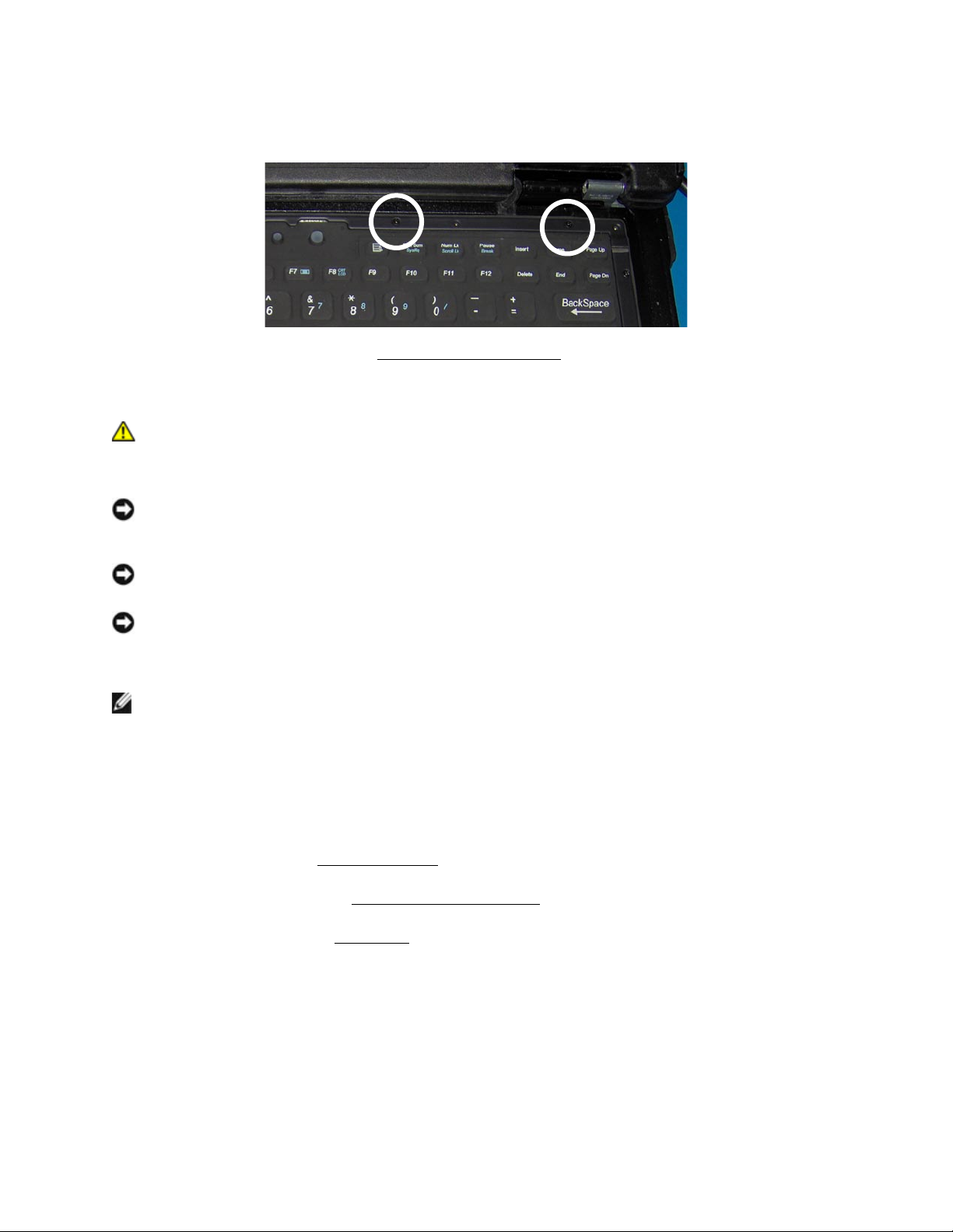
12. Fasten the 2 M2x6 screws shown in the image below to complete the installation of the top
metal bracket.
13. Replace the hinge cover (see
104H
Installing the Hinge Cover
).
9 Memory
CAUTION: Before you begin any of the procedures in this section, follow the safety
instructions in the XFR D630 Product Information Guide and in the XFR D630 User’s
Guide.
NOTICE: To avoid electrostatic discharge, ground yourself by using a wrist grounding strap or by
periodically touching an unpainted metal surface (such as a connector on the back of the
computer).
NOTICE: If your computer has only one memory module, install the memory module in the
connector labeled "DIMM A," which is underneath the keyboard.
NOTICE: If you remove your original memory modules from the computer during a memory
upgrade, keep them separate from any new modules that you may have, even if you purchased
the new modules from Dell. If possible, do not pair an original memory module with a new
memory module. Otherwise, your computer may not function at optimal performance.
NOTE: Memory modules purchased from Dell are covered under your computer warranty.
Your computer has two user-accessible SODIMM sockets, one accessed from beneath the keyboard
(DIMM A), and the other accessed from the bottom of the computer (DIMM B).
9.1 DIMM A
1. Follow the procedures in
105H
Before You Begin
.
2. Remove the hinge cover (see
106H
Removing the Hinge Cover
).
3. Remove the keyboard (see
107H
Keyboards
).
Page 52
DellTM XFR D630 Fully Rugged Notebook Service Manual
Page 52 of 106
Revision A01
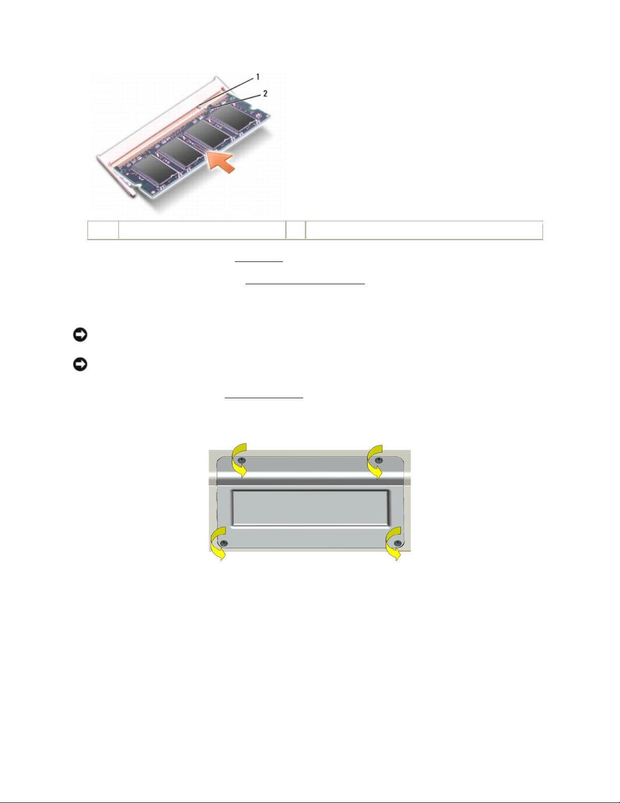
1
memory module (DIMM A)
2
securing clips (2)
NOTICE: To prevent damage to the memory module connector, do not use tools to spread the
memory-module securing clips.
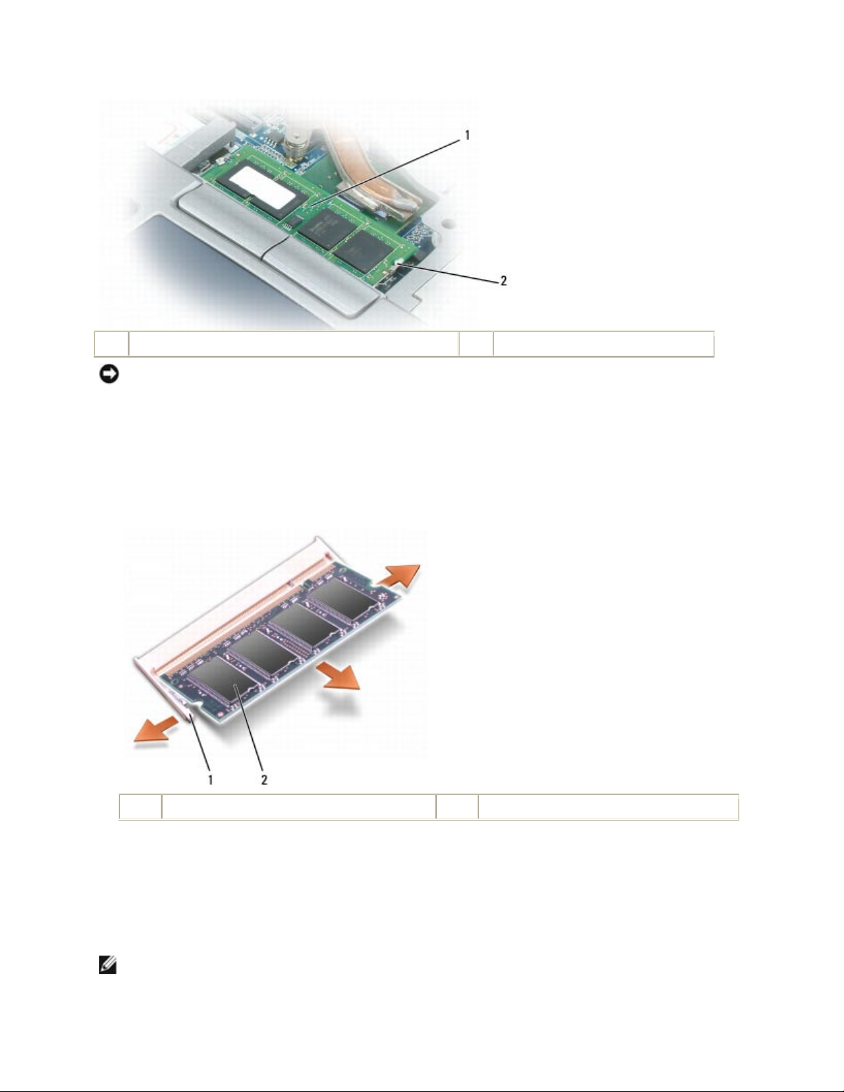
4. If you are replacing a memory module, ground yourself and remove the existing module:
a. Use your fingertips to carefully spread apart the securing clips on each end of the memory
module connector until the module pops up.
b. Remove the module from the connector.
1
securing clips (2)
2
memory module
5. Ground yourself and install the new memory module:
a. Align the notch in the module connector with the tab in the connector slot.
b. Slide the module firmly into the slot at a 45-degree angle, and rotate the module down
until it clicks into place. If you do not feel the click, remove the module and reinstall it.
NOTE: If the memory module is not installed properly, the computer may not boot properly.
No error message indicates this failure.
Page 53
DellTM XFR D630 Fully Rugged Notebook Service Manual
Page 53 of 106
Revision A01
1
tab 2 notch
6. Replace the keyboard (see
108H
Keyboards
).
7. Replace the hinge cover (see
109H
Installing the Hinge Cover
).
9.2 DIMM B
NOTICE: If you need to install memory modules in two connectors, install a memory module in
the connector labeled "DIMM A" before you install a module in the connector labeled "DIMM B."
NOTICE: Insert memory modules at a 45-degree angle to avoid damaging the connector.
1. Follow the procedures in
110H
Before You Begin
.
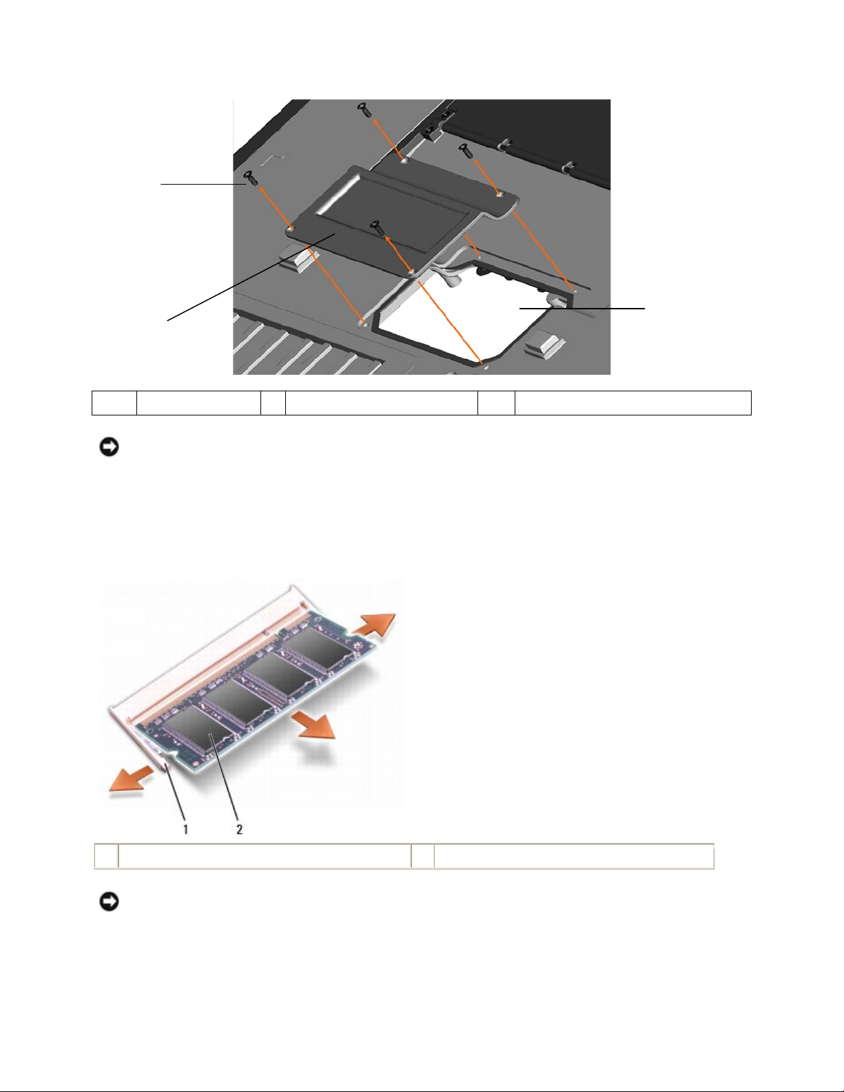
2. Turn the computer bottom-side up, remove the 4 screws that secure the memory module
cover, and then remove the cover.
Page 54
DellTM XFR D630 Fully Rugged Notebook Service Manual
Page 54 of 106
Revision A01
1
Screws (4)
2
Memory module cover
3
Memory module compartment
NOTICE: To prevent damage to the memory module connector, do not use tools to spread the
memory-module securing clips.
3. If you are replacing a memory module, ground yourself and remove the existing module:
a. Use your fingertips to carefully spread apart the securing clips on each end of the
memory module connector until the module pops up.
b. Remove the module from the connector.
1
securing clips (2)
2
memory module
NOTICE: Insert memory modules at a 45-degree angle to avoid damaging the connector.
4. Ground yourself and install the new memory module:
a. Align the notch in the module edge connector with the tab in the connector slot.
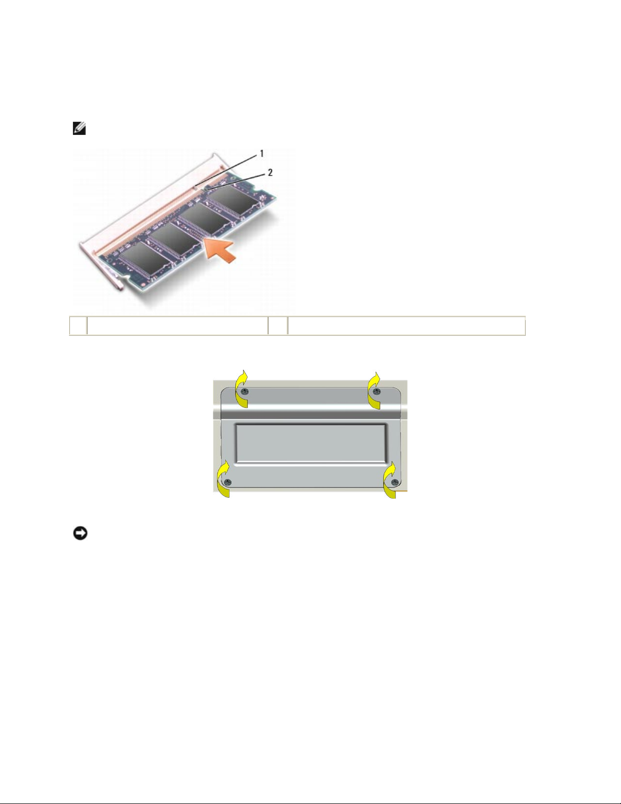
1
2
3
Page 55
DellTM XFR D630 Fully Rugged Notebook Service Manual
Page 55 of 106
Revision A01
b. Slide the module firmly into the slot at a 45-degree angle, and rotate the module
down until it clicks into place. If you do not feel the click, remove the module and
reinstall it.
NOTE: If the memory module is not installed properly, the computer may not boot properly. No
error message indicates this failure.
1
tab 2 notch
5. Replace the memory module cover, and use the 4 screws to secure the cover.
NOTICE: If the cover is difficult to close, remove the module and reinstall it. Forcing the cover to
close may damage your computer.
6. Insert the battery into the battery bay, or connect the AC adapter to your computer and an
electrical outlet.
7. Turn on the computer.
As the computer boots, it detects the additional memory and automatically updates the
system configuration information.
To confirm the amount of memory installed in the computer, click Start -> Help and Support ->
Use Tools to view your computer information and diagnose problems -> My Computer
Information.
10 Display Assembly
Page 56
DellTM XFR D630 Fully Rugged Notebook Service Manual
Page 56 of 106
Revision A01
10.1 Removing the Display Assembly
CAUTION: Before working inside your computer, follow the safety instructions in the
XFR D630 Product Information Guide and in the XFR D630 User’s Guide.
NOTICE: To avoid electrostatic discharge, ground yourself by using a wrist grounding strap or by
periodically touching an unpainted metal surface (such as a connector on the back of the
computer).
1. Follow the instructions in
111H
Before You Begin
.
2. Remove the hinge cover (see
112H
Removing the Hinge Cover
).
3. Remove the keyboard (see
113H
Keyboards
).
NOTICE: To avoid damage to your computer, carefully reroute the cables in the appropriate
cable channels when replacing the display. Route the gray and black antenna cables beneath the
white antenna cable, and the black display cable on top of the white antenna cable.
NOTICE: For the optional Touch Screen Display, remove the touch controller cable from the I/O
board on the right side, near the right hinge.
4. Unplug the display cable:
a. Pull straight up on the pull-tab that is attached to the display-feed flex cable to
disconnect the cable from the system board.
NOTE: The following step is only for the optional Touch Screen display.
b. Disconnect the touch controller cable from the motherboard controller cable,
above the heat sink.
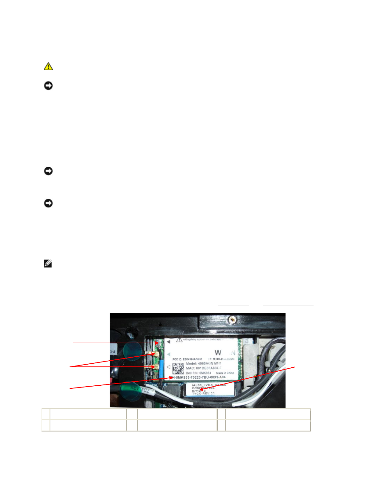
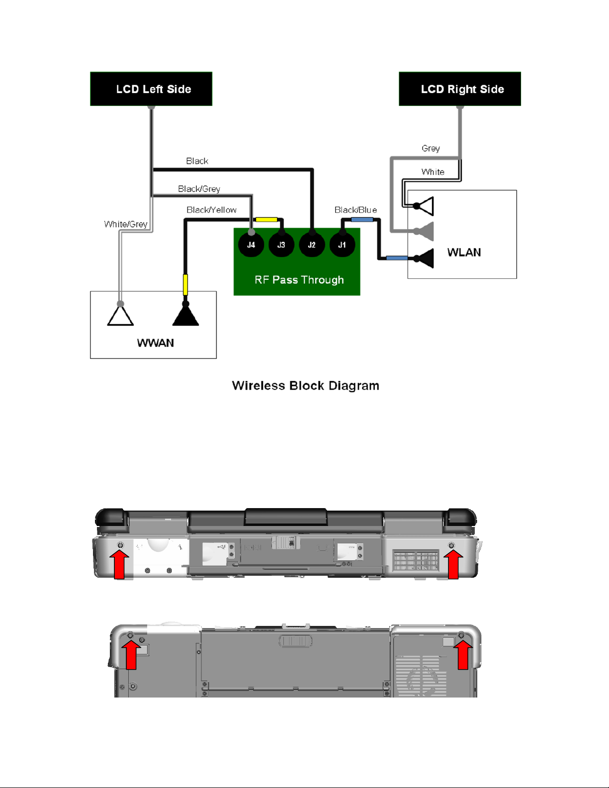
5. Disconnect the antenna cables from their card(s) (see
114H
WLAN Card
and
115H
RF Passthru Board
).
1
WLAN card
2
antenna cable connectors
3
RF Passthru cable connector
4
Display cable connector
1
2
3
4
Page 57
DellTM XFR D630 Fully Rugged Notebook Service Manual
Page 57 of 106
Revision A01
6. Carefully remove the antenna cables and the display cable from their routing guides.
7. Close the display.
8. Turn the computer upside-down with the back of the computer facing you.
9. From the back of the computer, remove the two M2.5 x 8-mm screws.
10. From the bottom of the computer, remove the two M2.5 x 8-mm screws.
11. Turn the computer right-side up and open the display.
Page 58
DellTM XFR D630 Fully Rugged Notebook Service Manual
Page 58 of 106
Revision A01
12. Lift the display assembly out of the base.
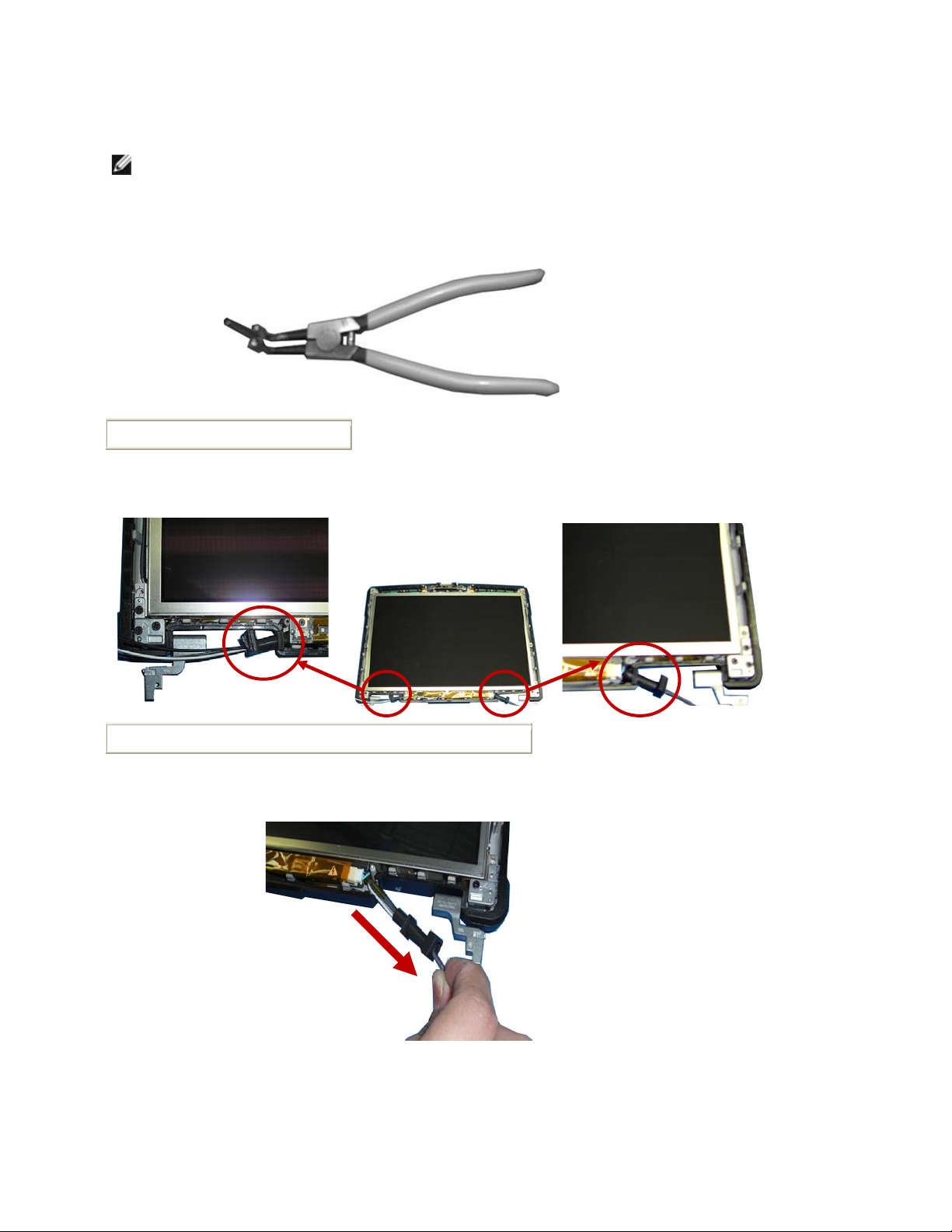
NOTE: The display grommets only need to be removed if you are replacing the display assembly
or replacing the display top cover assembly. The replacement kit will contain the grommet tool
that you need to perform the following steps. If your replacement kit does not contain the
grommet tool, do not perform the following steps.
Grommet tool
13. Follow these steps to remove the grommets from the left and right side of the display
assembly.
Location of left and right display grommets
a. To remove the right side grommet:
i. Lift and slide the grommet partially down the set of antenna cables
ii. Slide the ends of the grommet tool into the end of the grommet
Page 59
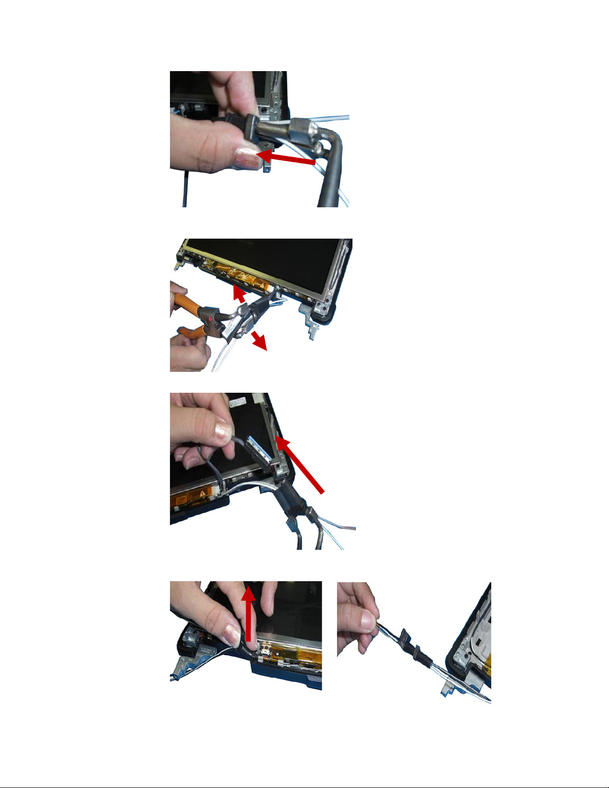
DellTM XFR D630 Fully Rugged Notebook Service Manual
Page 59 of 106
Revision A01
iii. Open the grommet tool, to allow the tool to stretch the grommet open.
iv. With the grommet stretched, pull the ends of the cables through the grommet.
b. To remove the left side grommet:
i. Lift and slide the grommet partially down the set of antenna cables.
ii. Slide the cables through the grommet.
Page 60

DellTM XFR D630 Fully Rugged Notebook Service Manual
Page 60 of 106
Revision A01
10.2 Installing the Display Assembly
NOTICE: To avoid damage to your computer, when replacing the display assembly be careful to
reroute the cables in the appropriate cable channels.
NOTE: If the display assembly was disassembled, the grommets had to be removed. The
following steps explain how to install the grommets. If the grommets are already installed on the
display cables, skip to step 2.
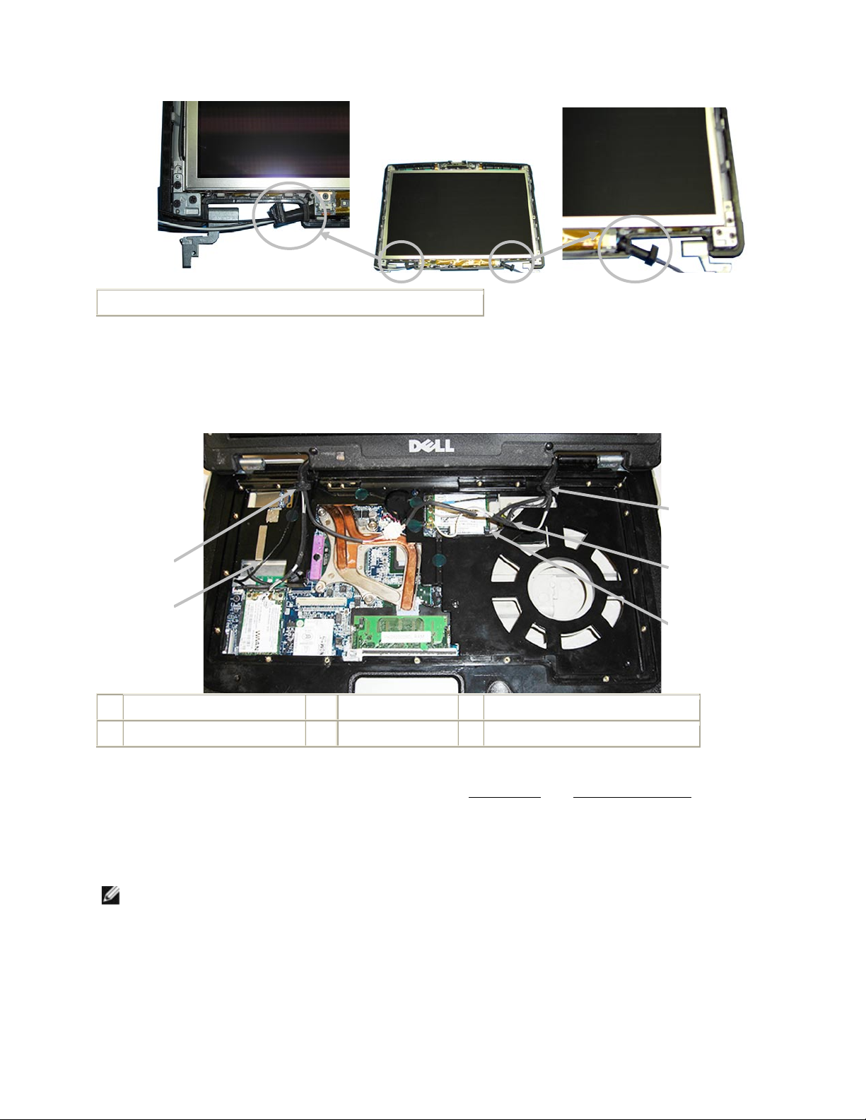
1. Install the display cable grommets on the left and right side of the display assembly.
a. To install the right side grommet, use the grommet tool to spread the grommet open,
and slide the cables through the grommet
b. To install the left side grommet, slide the left side cables through the grommet.
Page 61
DellTM XFR D630 Fully Rugged Notebook Service Manual
Page 61 of 106
Revision A01
Location of left and right display grommets
2. From the bottom of the computer, install the two M2.5 x 8-mm screws.
3. From the back of the computer, install the two M2.5 x 8-mm screws.
4. Carefully place the antenna cables and the display cable into their routing guides.
1
Left side grommet
2
Antenna cable
3
Right side grommet
4
Antenna cables
5
Display cable
5. Connect the antenna cables to their card(s) (see
116H
WLAN Card
and
117H
RF Passthru Board
).
6. Connect the display cable:
a. Attach the display-feed flex cable to the system board.
NOTE: The following step is only for the optional Touch Screen display.
b. Attach the touch controller cable to the motherboard controller cable, above the
heat sink.
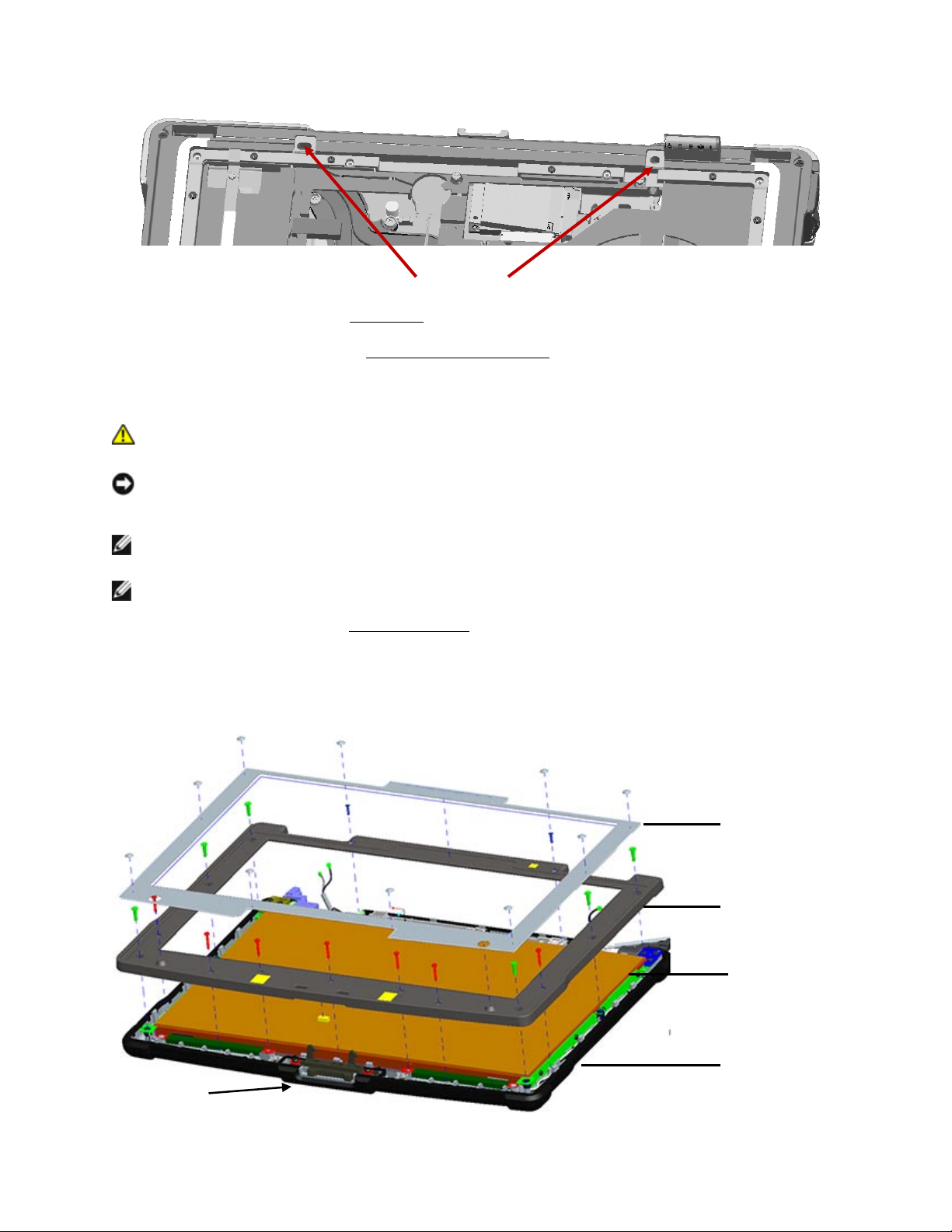
7. Seat the cable grommets into the square cavities on each side of the palm rest base.
1
2
3
4
5
Page 62
DellTM XFR D630 Fully Rugged Notebook Service Manual
Page 62 of 106
Revision A01
Grommets
8. Install the keyboard (see
118H
Keyboards
).
9. Install the hinge cover (see
119H
Installing the Hinge Cover
).
10.3 Removing the Display Bezel
CAUTION: Before working inside your computer, follow the safety instructions in the
XFR D630 Product Information Guide and in the XFR D630 User’s Guide.
NOTICE: To avoid electrostatic discharge, ground yourself by using a wrist grounding strap or by
periodically touching an unpainted metal surface (such as a connector on the back of the
computer).
NOTE: Replacing the display bezel does not require removing the display assembly from the
base.
NOTE: Replacement keyboard/palm rest overlays are not included in the bezel service kits.
1. Follow the instructions in
120H
Before You Begin
.
2. Turn the computer top-side up, and then open the display all the way (160 degrees).
3. Remove bezel overlay. Start in the upper left or right corner to peel the overlay off of the
bezel.
1
2
3
4
Top of Display
Page 63
DellTM XFR D630 Fully Rugged Notebook Service Manual
Page 63 of 106
Revision A01
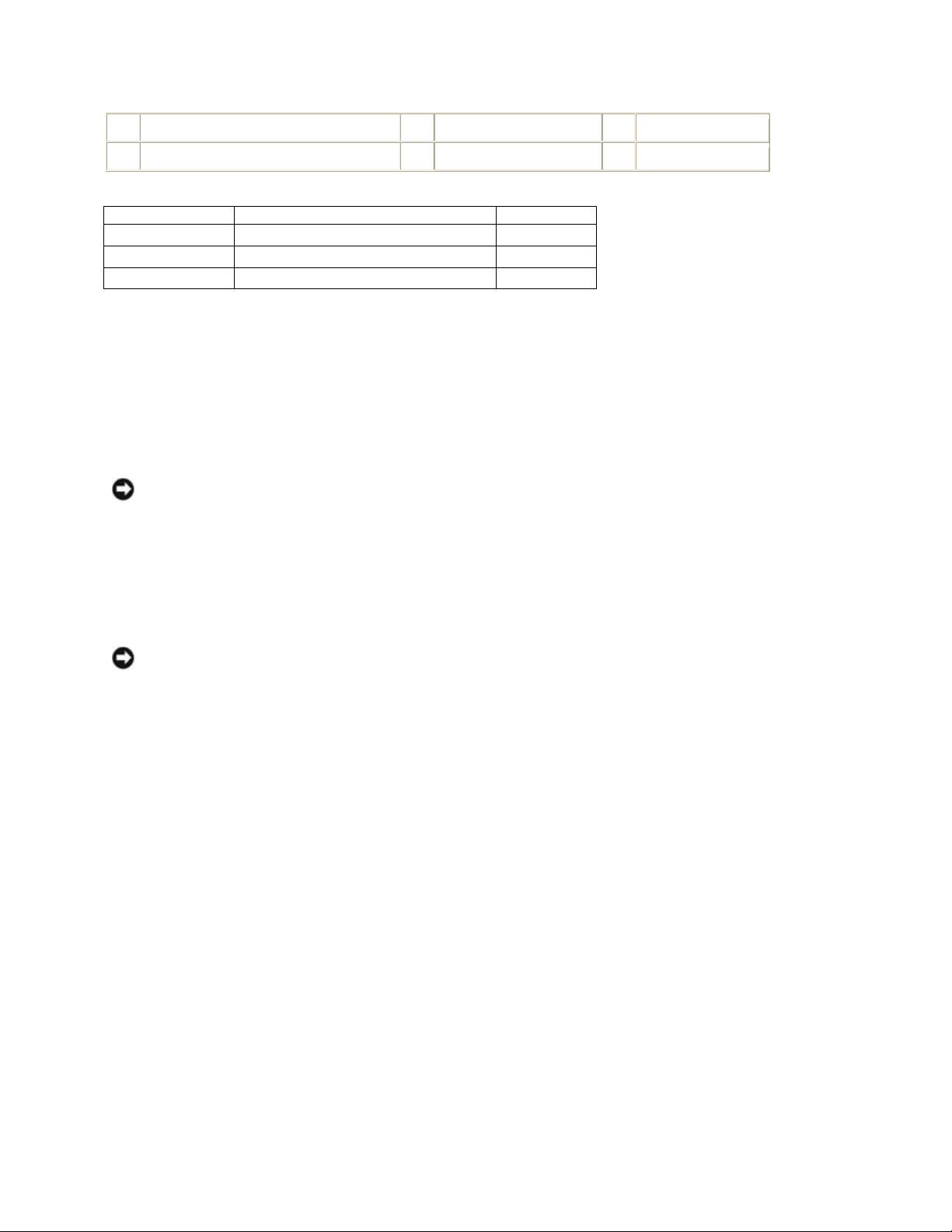
1
display bezel overlay
2
display bezel
3
display panel
4
display back cover
PART NUMBER
SCREW TYPE
QUANTITY
18428
CSK SCREW M2 X 8-BLACK
2
18417
PAN HEAD SCREW M2 X 12-BLACK
7
18114
SHOULDER SCREW M2.5
6
4. Remove the fifteen (15) screws that secure the bezel:
• Two - SCR,M2X8,PHH,MSCR,ZPS,XFR
• Seven - SCR,M2X12,PHH,MSCR,ZPS,XFR
• Six - SCR,M2.5X10,PHH,MSCR,SHLDR,XFR
NOTICE: Carefully separate the bezel from the display back cover to avoid damage to the bezel.
5. Starting from the outside edges of the bezel, use your fingers to gently pry the bezel upward
from the display panel. Release the sides of the bezel next; if necessary, use a plastic scribe
to carefully release the corners of the bezel from the display panel.
10.4 Installing the Display Bezel
NOTICE: To avoid damaging the computer when replacing the display bezel, ensure that the
bezel edges line up with those on the display back cover, and snap into place around the entire
perimeter of the display back cover.
1. Align the display bezel, and install the fifteen (15) screws that secure the bezel:
• Two - SCR,M2X8,PHH,MSCR,ZPS,XFR
• Seven - SCR,M2X12,PHH,MSCR,ZPS,XFR
• Six - SCR,M2.5X10,PHH,MSCR,SHLDR,XFR
2. Install the new bezel overlay.
a. Remove the backing material from the bezel overlay.
b. Initially position the overlay around the top two Display bumpers.
c. Press evenly and firmly to apply the overlay.
3. Install the 2 screw covers to the bottom center screws.
4. Remove the 8 screw covers from the original bezel overlay and apply to the new overlay.
Each screw cover location on the overlay is marked by a white dot.
10.5 Removing the Display Panel
Page 64
DellTM XFR D630 Fully Rugged Notebook Service Manual
Page 64 of 106
Revision A01
CAUTION: Before working inside your computer, follow the safety instructions in the
XFR D630 Product Information Guide and in the XFR D630 User’s Guide.
NOTICE: To avoid electrostatic discharge, ground yourself by using a wrist grounding strap or by
periodically touching an unpainted metal surface (such as a connector on the back of the
computer).
1. Follow the instructions in
121H
Before You Begin
.
2. Remove the display assembly (see
122H
Removing the Display Assembly
).
NOTE: Ensure the display cable grommets were removed by following the grommet removal
instructions provided in
123H
Removing the Display Assembly
at step 13.
3. Remove the display bezel (see
124H
Removing the Display Bezel
).
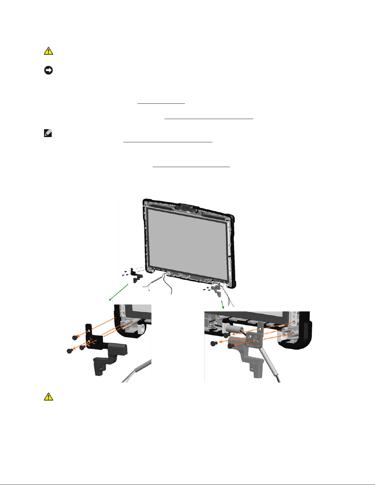
4. Remove hinges. Remove 3 M2.5 x 5-mm screws from each side of the display panel and
remove the hinge from each side.
CAUTION: To avoid damage to your display panel, handle the panel by the bracket tabs
only.
5. Pull the LVDS cable thru the rubber grommet in the LVDS/antenna cable assembly, near the
right side hinge. These antenna cables are part of the back cover assembly and must be
separated from the LVDS cable to allow removal of the Display Panel.
Page 65
DellTM XFR D630 Fully Rugged Notebook Service Manual
Page 65 of 106
Revision A01
6. For the optional Touch Screen displays, pull the touch controller cable through the rubber
grommet in the antenna cable assembly on the left side hinge. These antenna cables are part
of the back cover assembly and must be separated from the touch controller cable to allow for
the removal of the Display Panel.
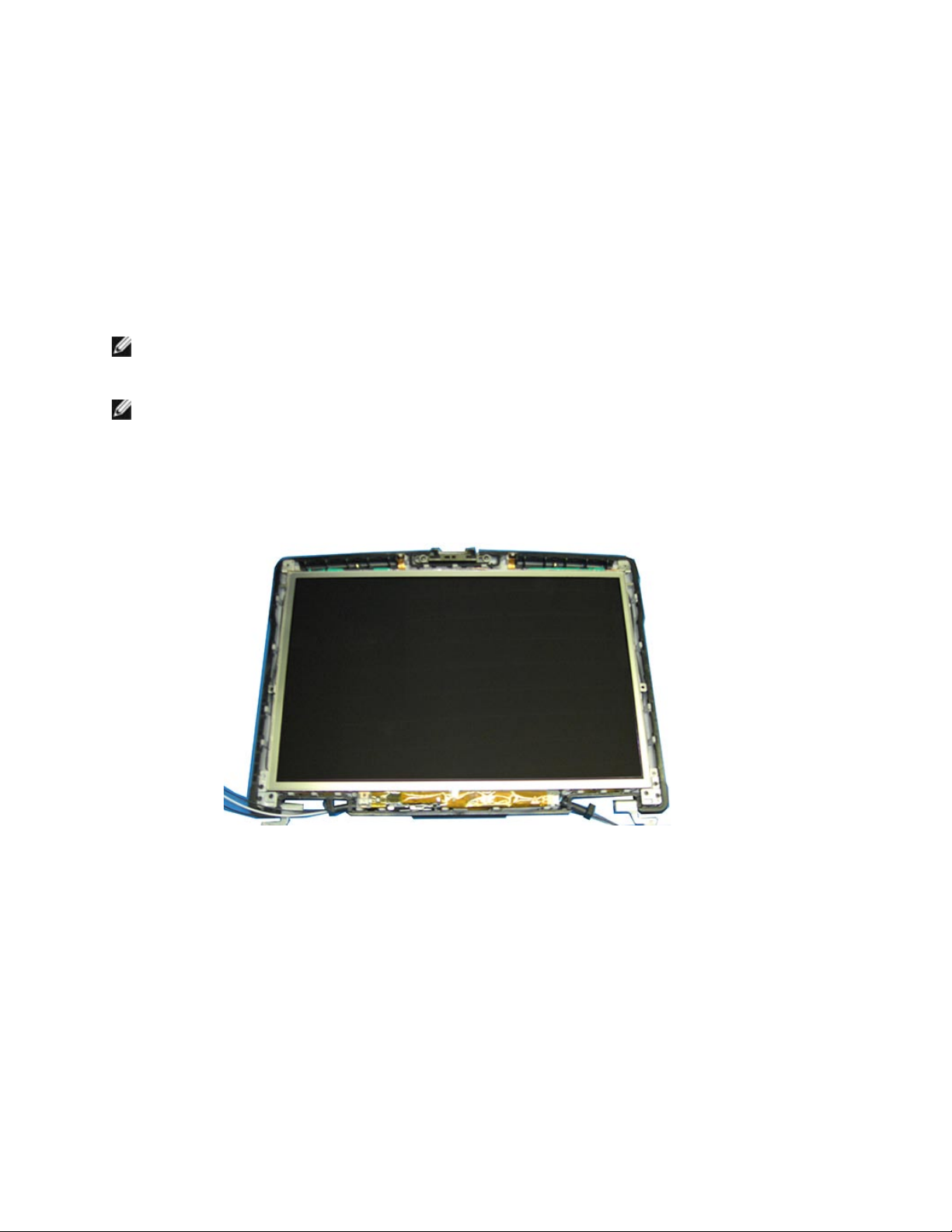
7. Lift the display panel a few inches from the display back cover.
8. Draw the LED ribbon-cable release tab away from the display panel to release the ribbon
cable, and lift the display panel fully from the display back cover.
10.6 Installing the Display Panel
NOTE: Remove the replacement display panel assembly from its packaging. The new part will
have packing material covering the LVDS connector. The LVDS cable will be taped to the back of
the panel on top of the copper foil backing so care is needed during tape removal.
NOTE: For optional Touch Screen Display panels, the touch controller cable is also taped to the
back of the panel on top of the copper foil backing, and similar care is needed during tape
removal.
1. Connect the LED cable.
2. Align the display panel in the top cover.
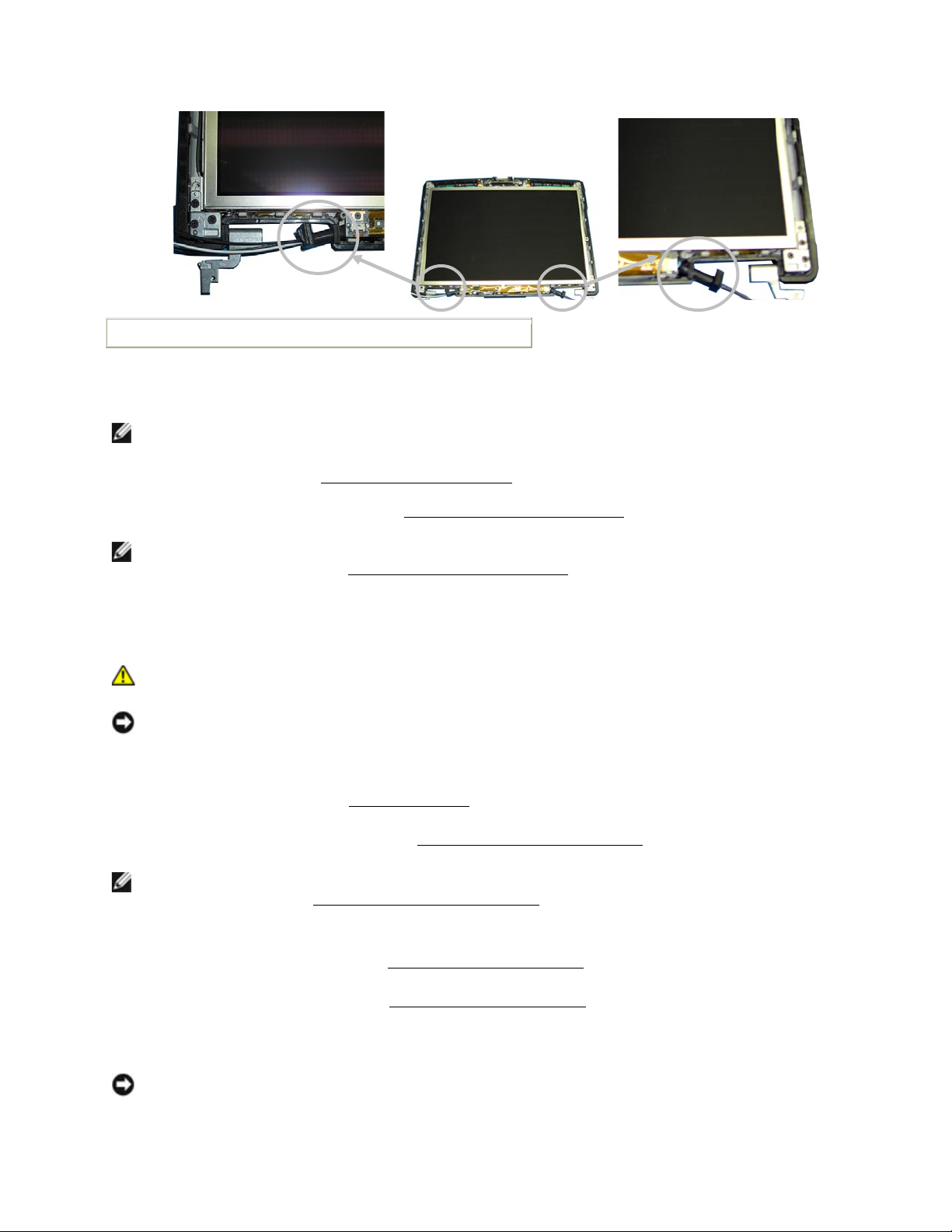
3. Check cable routing on each side of the inverter. On the right side, verify LVDS cable and
antenna cables are correctly placed to exit the top cover as shown. On the left side, verify
antenna cables and touch controller cable (for touch screen Displays only) are correctly placed
to exit the top cover as shown above.
4. Route cables into the grommets on each side using the grommet tool.
5. Align grommet on each side with top cover edge, to seal the opening where cables exit the
Display Assembly.
Page 66
DellTM XFR D630 Fully Rugged Notebook Service Manual
Page 66 of 106
Revision A01
Location of left and right display grommets
6. Install hinge on each side, on top of display panel brackets. Secure each hinge to top cover
with 3 M2.5 X 5-mm screws.
NOTE: Hinges are labeled R (right) and L (left) and must be installed on the correct side.
7. Install the bezel (see
125H
Installing the Display Bezel
).
8. Install the display assembly (see
126H
Installing the Display Assembly
).
NOTE: Ensure the display cable grommets are properly installed by following the instructions
provided at the beginning of
127H
Installing the Display Assembly
.
10.7 Removing the Display Top Cover
CAUTION: Before working inside your computer, follow the safety instructions in the
XFR D630 Product Information Guide and in the XFR D630 User’s Guide.
NOTICE: To avoid electrostatic discharge, ground yourself by using a wrist grounding strap or by
periodically touching an unpainted metal surface (such as a connector on the back of the
computer).
1. Follow the instructions in
128H
Before You Begin
.
2. Remove the display assembly (see
129H
Removing the Display Assembly
).
NOTE: Ensure the display cable grommets were removed by following the grommet removal
instructions provided in
130H
Removing the Display Assembly
at step 13.
3. Remove the display bezel (see
131H
Removing the Display Bezel
).
4. Remove the display panel (see
132H
Removing the Display Panel
).
10.8 Installing the Display Top Cover
NOTE: If replacing the display top cover, remove the replacement display top cover from its
packaging. The new part will have a mylar covering. The antenna cable will be taped to the
inside of the cover. Carefully remove the tape from the antenna cable.
Page 67
DellTM XFR D630 Fully Rugged Notebook Service Manual
Page 67 of 106
Revision A01
1. Follow the instructions in
133H
Before You Begin
.
2. Install the display panel (see
134H
Installing the Display Panel
).
3. Install the display bezel (see
135H
Installing the Display Bezel
).
4. Install the display assembly (see
136H
Installing the Display Assembly
)
NOTE: Ensure the display cable grommets are properly installed by following the instructions
provided at the beginning of
137H
Installing the Display Assembly
.
10.9 Removing the Display Latch
CAUTION: Before working inside your computer, follow the safety instructions in the
XFR D630 Product Information Guide and in the XFR D630 User’s Guide.
NOTICE: To avoid electrostatic discharge, ground yourself by using a wrist grounding strap or by
periodically touching an unpainted metal surface (such as a connector on the back of the
computer).
NOTE: Replacing the display latch does not require removing the display assembly from the
base.
NOTE: Replacement keyboard/palm rest overlays are not included in the latch service kits.
1. Follow the procedures in
138H
Before You Begin
.
2. Turn the computer top-side up, and then open the display all the way (160 degrees).
3. Remove the display bezel (see
139H
Removing the Display Bezel
).
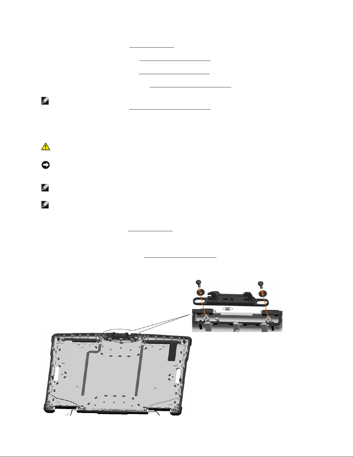
4. Remove the 2 latch screws and washers.
Page 68

DellTM XFR D630 Fully Rugged Notebook Service Manual
Page 68 of 106
Revision A01
5. Remove the latch spring from the top cover and slide the latch out of the top cover.
10.10 Installing the Display Latch
1. Install the latch and secure with the 2 screws and washers. Do not fully tighten screws at this
time.
2. Apply the spring to the latch, and then to the top cover hook.
3. Tighten the 2 screws installed in step 1.
4. Check the latch movement.
5. Install the display bezel (see
140H
Installing the Display Bezel
).
11 Internal Card with Bluetooth® Wireless
Technology
CAUTION: Before working inside your computer, follow the safety instructions in your
XFR D630 Product Information Guide and in the XFR D630 User’s Guide.
NOTICE: To avoid electrostatic discharge, ground yourself by using a wrist grounding strap or by
periodically touching a connector on the back panel of the computer.
NOTICE: To avoid damaging the system board, you must remove the main battery before you
begin working inside the computer (see
141H
Before Working Inside Your Computer
).
11.1 Removing the Bluetooth® Wireless Card
1. Follow the procedures in
142H
Before You Begin
.
2. Remove the hinge cover (see
143H
Removing the Hinge Cover
).
3. Remove the keyboard (see
144H
Keyboards
).
NOTICE: Be careful when removing the card to avoid damaging the card, card cable, or
surrounding components.
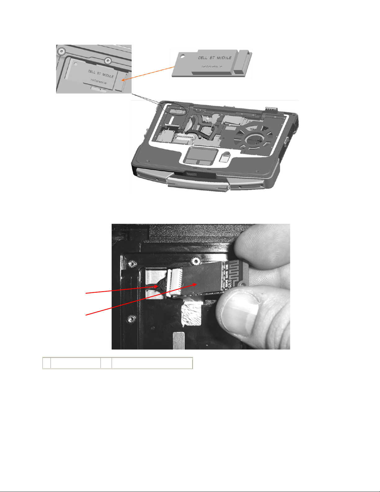
4. Use the plastic scribe to gently pry the card out of its compartment. The card is located
upside-down in the compartment.
Page 69
DellTM XFR D630 Fully Rugged Notebook Service Manual
Page 69 of 106
Revision A01
5. Lift the card from the compartment, ensuring that you do not pull on the card cable with
excessive force.
1
Wireless card
2
Wireless card cable
6. Disconnect the card from the cable and remove the card from the computer.
11.2 Installing the Bluetooth® Wireless Card
1. Grasp the Bluetooth Wireless cable, and gently extend it.
2. Connect the Bluetooth Wireless Card to the cable.
3. Gently insert the card into its compartment.
1
2
Page 70

DellTM XFR D630 Fully Rugged Notebook Service Manual
Page 70 of 106
Revision A01
4. Install the keyboard (see
145H
Keyboards
).
5. Install the hinge cover (see
146H
Installing the Hinge Cover
).
12 WWAN, FCM & SIM Cards
12.1 Mobile Broadband Network (WWAN) Card
NOTE: Mobile Broadband network cards may not be available in certain regions.
If you ordered a Mobile Broadband network card with your computer, the card is already installed.
CAUTION: Before you begin any of the procedures in this section, follow the safety
instructions in the XFR D630 Product Information Guide and in the XFR D630 User’s
Guide.
NOTICE: To avoid electrostatic discharge, ground yourself by using a wrist grounding strap or by
periodically touching an unpainted metal surface (such as a connector on the back of the
computer).
NOTE: The WWAN card slot is located on the left center, next to the keyboard connector.
1. Follow the procedures in
147H
Before You Begin
.
2. Remove the hinge cover (see
148H
Removing the Hinge Cover
).
3. Remove the keyboard (see
149H
Keyboards
).
NOTICE: To prevent damage to the connector, do not use tools to release the securing tabs.
NOTICE: Do not insert a WLAN card into the Mobile Broadband network card connector. The
WWAN slot is marked WWAN/FCM.
4. If a Mobile Broadband network card is not already installed, go to step 5. If you are replacing
a Mobile Broadband network card, remove the existing card:
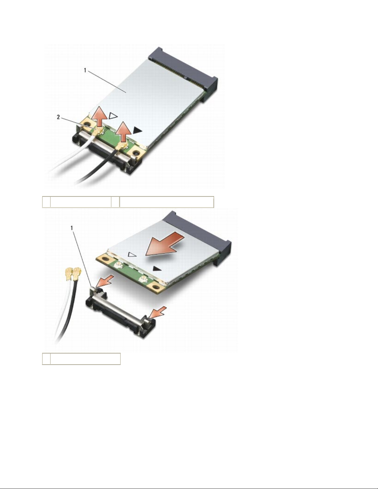
a. Disconnect the antenna cables from the Mobile Broadband network card.
b. Release the card by pushing the metal securing tabs away from the card until the card
pops up slightly.
c. Slide the card at a 45-degree angle out of its connector.
NOTICE: The connectors are keyed to ensure correct insertion. If you feel resistance, check the
connectors and realign the card.
Page 71
DellTM XFR D630 Fully Rugged Notebook Service Manual
Page 71 of 106
Revision A01
1
WWAN card
2
antenna cable connectors
1
metal securing tabs (2)
Page 72
DellTM XFR D630 Fully Rugged Notebook Service Manual
Page 72 of 106
Revision A01
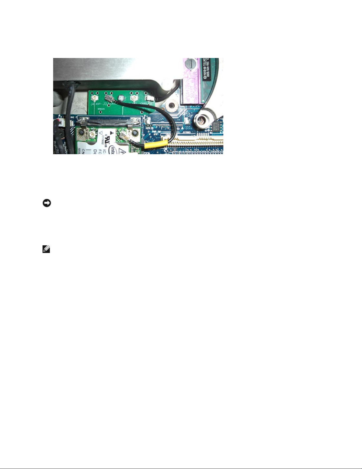
WWAN with Passthu Board & Passthru Cable
5. To install a Mobile Broadband network card:
a. Move any antenna cables out of the way to make space for the Mobile Broadband
network card.
NOTICE: To avoid damaging the Mobile Broadband network card, never place cables on top of or
under the card and ensure that you route the cables properly.
b. Insert the card into the system board connector at a 45-degree angle, and press the
card into the metal securing tabs until you feel a click.
NOTE: For more specific information about which cable to connect to which connector, see the
documentation that came with your Mobile Broadband network card.
6. Connect the antenna cables to the Mobile Broadband network card, ensuring that you route
the cables correctly.
Page 73
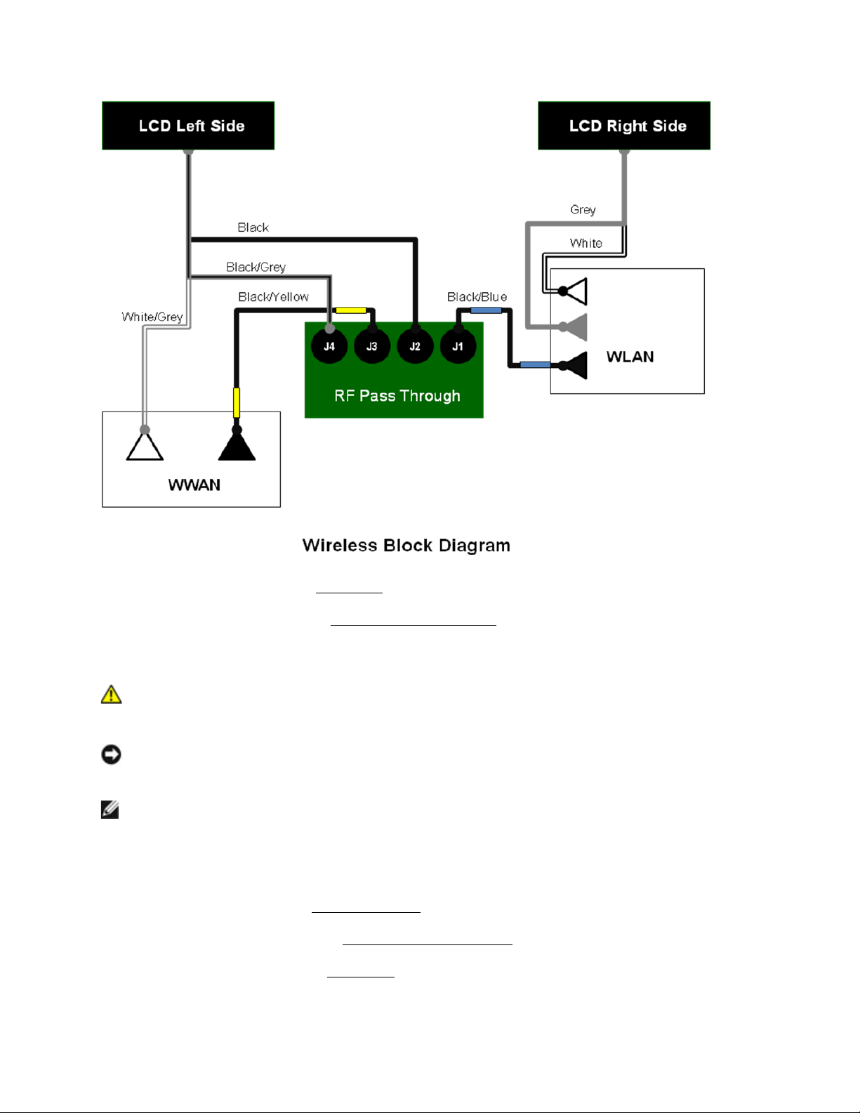
DellTM XFR D630 Fully Rugged Notebook Service Manual
Page 73 of 106
Revision A01
7. Install the keyboard (see
150H
Keyboards
).
8. Install the hinge cover (see
151H
Installing the Hinge Cover
).
12.2 Flash Cache Module
CAUTION: Before you begin any of the procedures in this section, follow the safety
instructions in the XFR D630 Product Information Guide and in the XFR D630 User’s
Guide.
NOTICE: To avoid electrostatic discharge, ground yourself by using a wrist grounding strap or by
periodically touching an unpainted metal surface (such as a connector on the back of the
computer).
NOTE: The WWAN card slot is located on the left center, next to the keyboard connector. The
FCM is installed into the WWAN card slot.
12.2.1 Removing the Flash Cache Module
1. Follow the procedures in
152H
Before You Begin
.
2. Remove the hinge cover (see
153H
Removing the Hinge Cover
).
3. Remove the keyboard (see
154H
Keyboards
).
Page 74
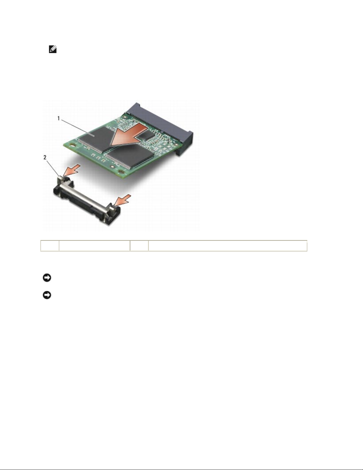
DellTM XFR D630 Fully Rugged Notebook Service Manual
Page 74 of 106
Revision A01
NOTE: If you leave the area, ground yourself again when you return to the computer.
4. Release the FCM by pushing the metal securing brackets away from the card until the card
pops up slightly.
5. Remove the FCM.
1
FCM Card
2
metal securing tabs (2)
12.2.2 Installing the Flash Cache Module
NOTICE: Install the FCM in the WWAN/FCM slot. Do not install an FCM in the WLAN card slot.
Doing so may cause damage to your computer.
NOTICE: Ensure that the antenna cables remain out of the way. The antenna cables need to be
routed above the WWAN/FCM slot in the area near the fan cable connector.
Page 75
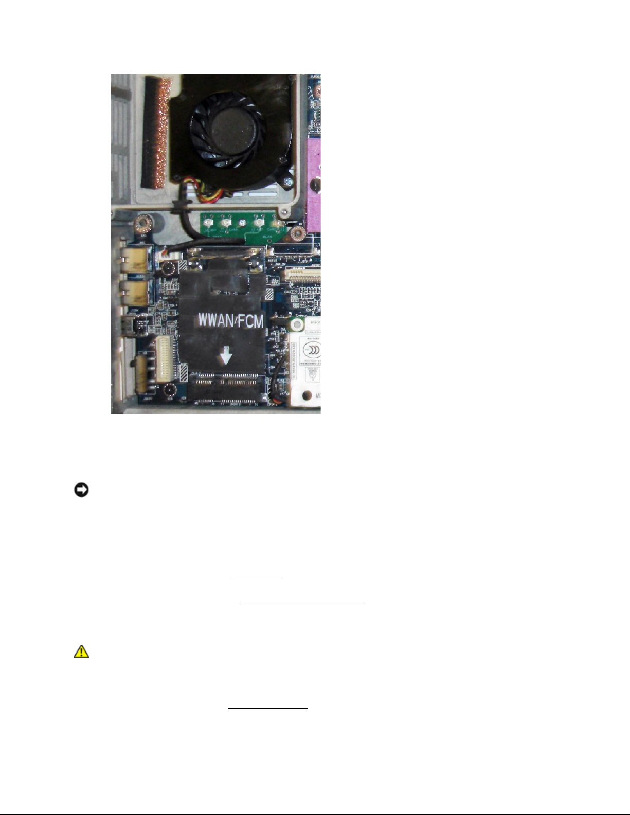
DellTM XFR D630 Fully Rugged Notebook Service Manual
Page 75 of 106
Revision A01
1. To install a FCM card:
a. Move any antenna cables out of the way to make space for the FCM card.
NOTICE: To avoid damaging the FCM card, never place cables on top of or under the card and
ensure that you route the cables properly.
b. Insert the card into the system board connector at a 45-degree angle, and press the
card into the metal securing tabs until you feel a click.
2. Install the keyboard (see
155H
Keyboards
).
3. Install the hinge cover (see
156H
Installing the Hinge Cover
).
12.3 Subscriber Identity Module (SIM) Card
CAUTION: Before you begin any of the procedures in this section, follow the safety
instructions in the XFR D630 Product Information Guide and in the XFR D630 User’s
Guide.
1. Follow the procedures in
157H
Before You Begin
.
Page 76
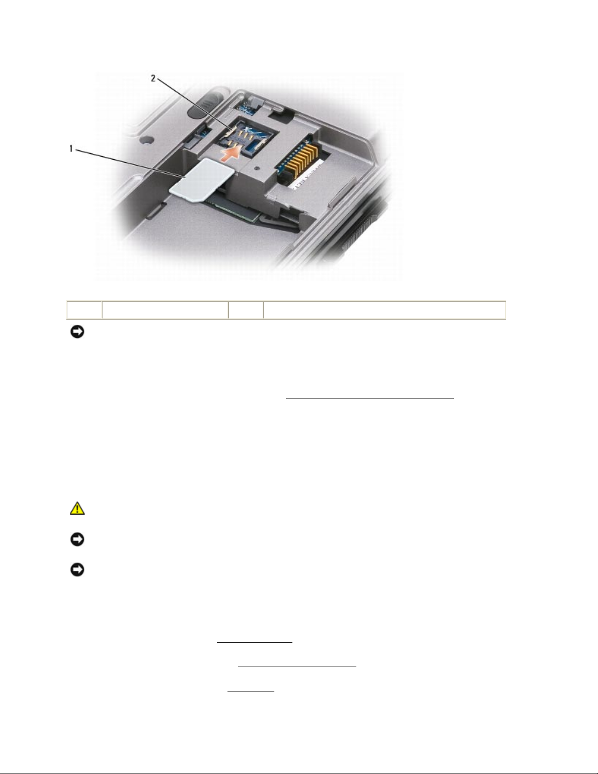
DellTM XFR D630 Fully Rugged Notebook Service Manual
Page 76 of 106
Revision A01
1
SIM card
2
metal brackets (2)
NOTICE: To prevent electrostatic discharge (ESD), hold the card in your hand before you insert
or remove the card. Do not touch the SIM card connectors.
2. Turn the computer upside-down with the front of the computer facing you.
3. Ensure that the battery is removed (see
158H
Before Working Inside Your Computer
).
4. With the cut-off corner on the card facing away from the card compartment, insert the SIM
card into the compartment (as shown) so that it slides under the metal bracket on the sides.
5. Replace the battery and battery cover.
13 Coin-Cell Battery
CAUTION: Before working inside your computer, follow the safety instructions in your
XFR D630 Product Information Guide and in the XFR D630 User’s Guide.
NOTICE: To avoid electrostatic discharge, ground yourself by using a wrist grounding strap or by
periodically touching a connector on the back panel of the computer.
NOTICE: To avoid damaging the system board, you must remove the main battery before you
begin working inside the computer.
13.1 Removing the Coin-Cell Battery
1. Follow the procedures in
159H
Before You Begin
.
2. Remove the hinge cover (see
160H
Removing the Hinge Cover
).
3. Remove the keyboard (see
161H
Keyboards
).
Page 77
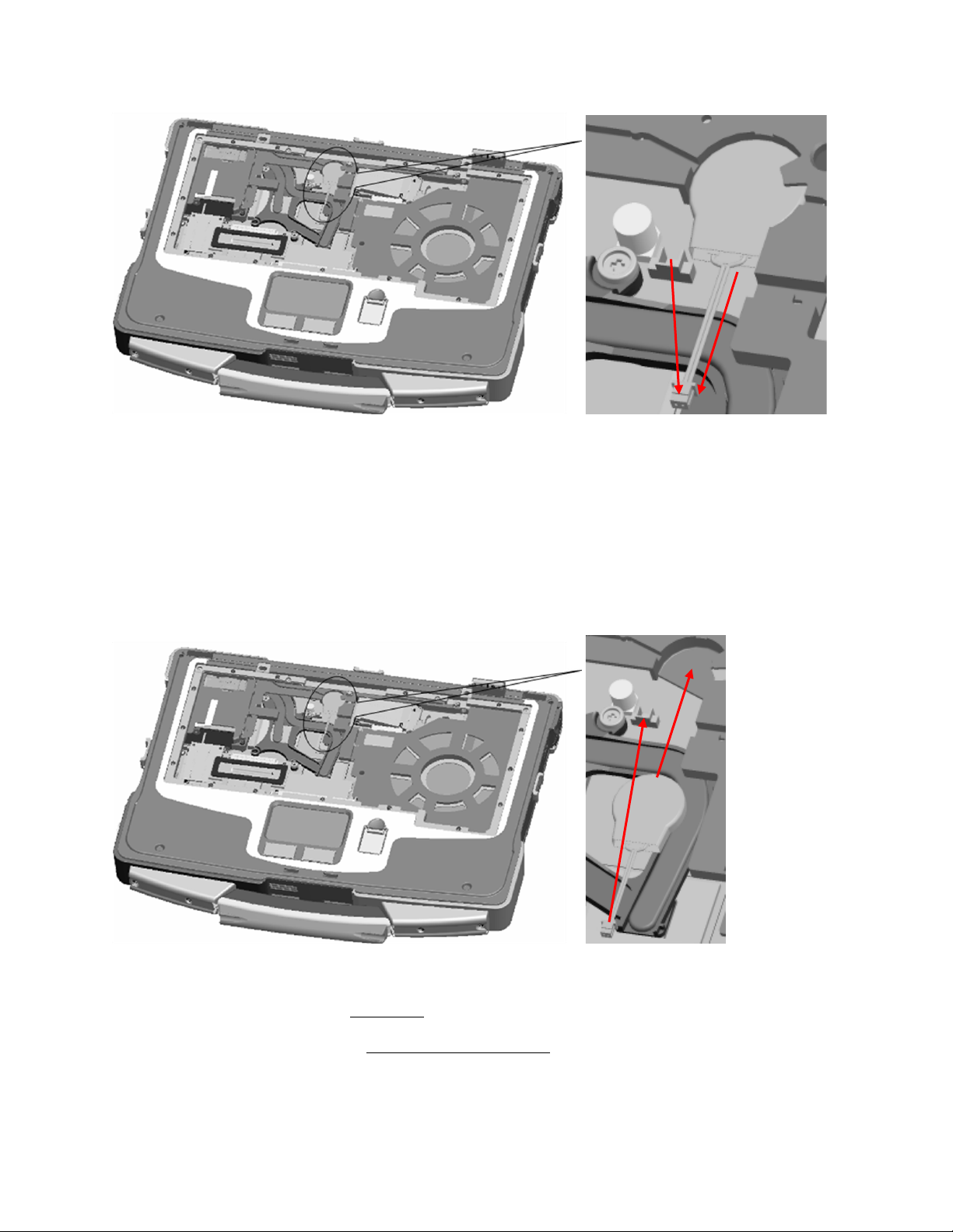
DellTM XFR D630 Fully Rugged Notebook Service Manual
Page 77 of 106
Revision A01
4. Remove the battery cable connector from the connector on the system board.
5. Being careful not to break the plastic, lift the battery slightly and slide the battery out from
under the plastic tab until it has been removed from the battery compartment.
13.2 Installing the Coin-Cell Battery
1. Being careful not to break the plastic, lift the plastic tab slightly, and gently “toe” in the coincell battery at an angle and push into the battery compartment.
2. Connect the battery cable connector to the connector on the system board.
3. Install the keyboard (see
162H
Keyboards
).
4. Install the hinge cover (see
163H
Installing the Hinge Cover
).
5. Install the battery.
Page 78
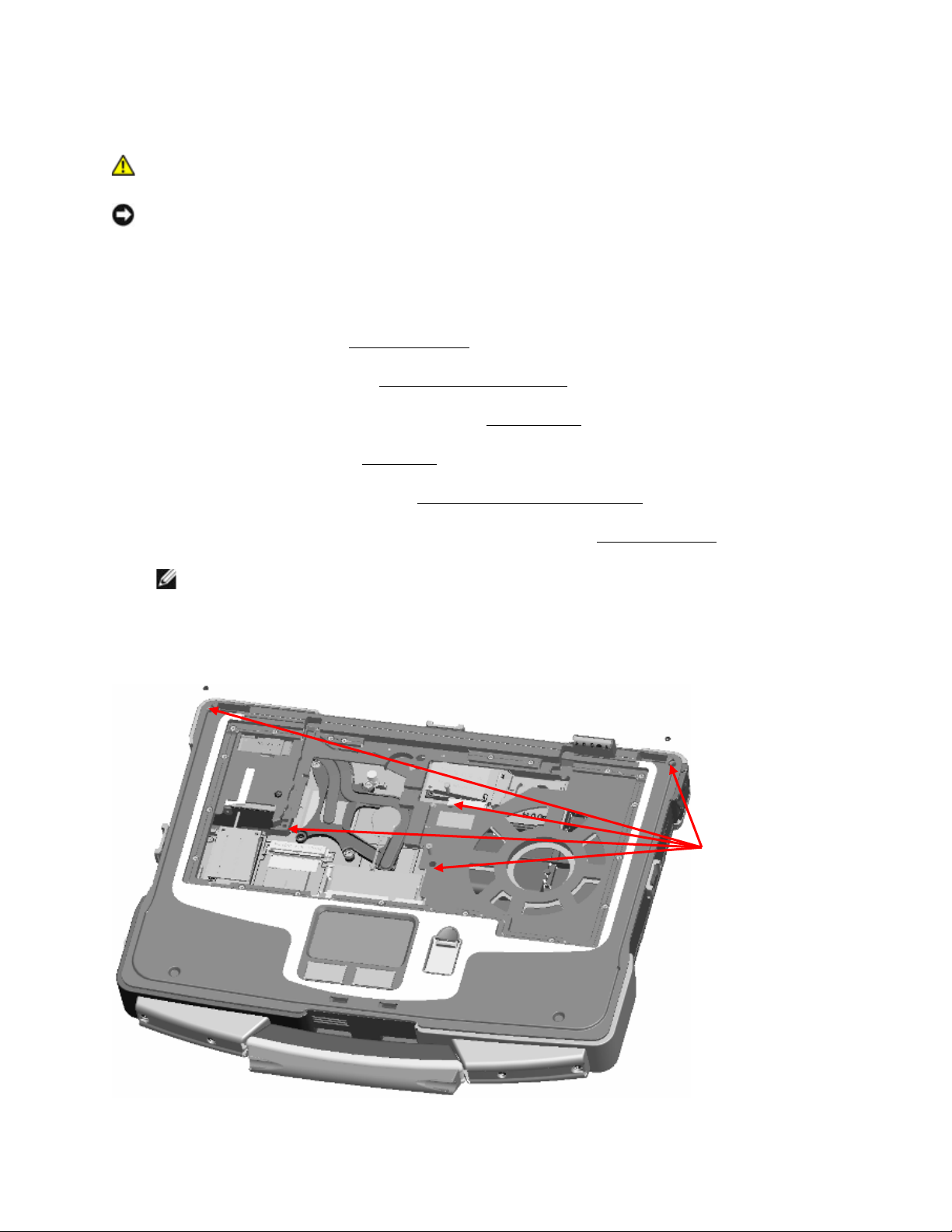
DellTM XFR D630 Fully Rugged Notebook Service Manual
Page 78 of 106
Revision A01
14 Palm Rest
CAUTION: Before working inside your computer, follow the safety instructions in the
XFR D630 Product Information Guide and in the XFR D630 User’s Guide.
NOTICE: To avoid electrostatic discharge, ground yourself by using a wrist grounding strap or by
periodically touching an unpainted metal surface (such as a connector on the back of the
computer).
14.1 Removing the Palm Rest
1. Follow the instructions in
164H
Before You Begin
.
2. Remove the hinge cover (see
165H
Removing the Hinge Cover
).
3. Remove any installed media bay device (see
166H
XBay Devices
).
4. Remove the keyboard (see
167H
Keyboards
).
5. Remove the display assembly (see
168H
Removing the Display Assembly
).
6. Disconnect the coin-cell battery from the system board (see
169H
Coin-Cell Battery
).
NOTE: You can leave the coin-cell battery in place (on the palm rest) unless you are
installing a replacement palm rest, in which case you need to remove the coin-cell battery
and place it in the replacement palm rest.
7. Remove the five screws from the top of the palm rest.
Palm rest
screws
Page 79
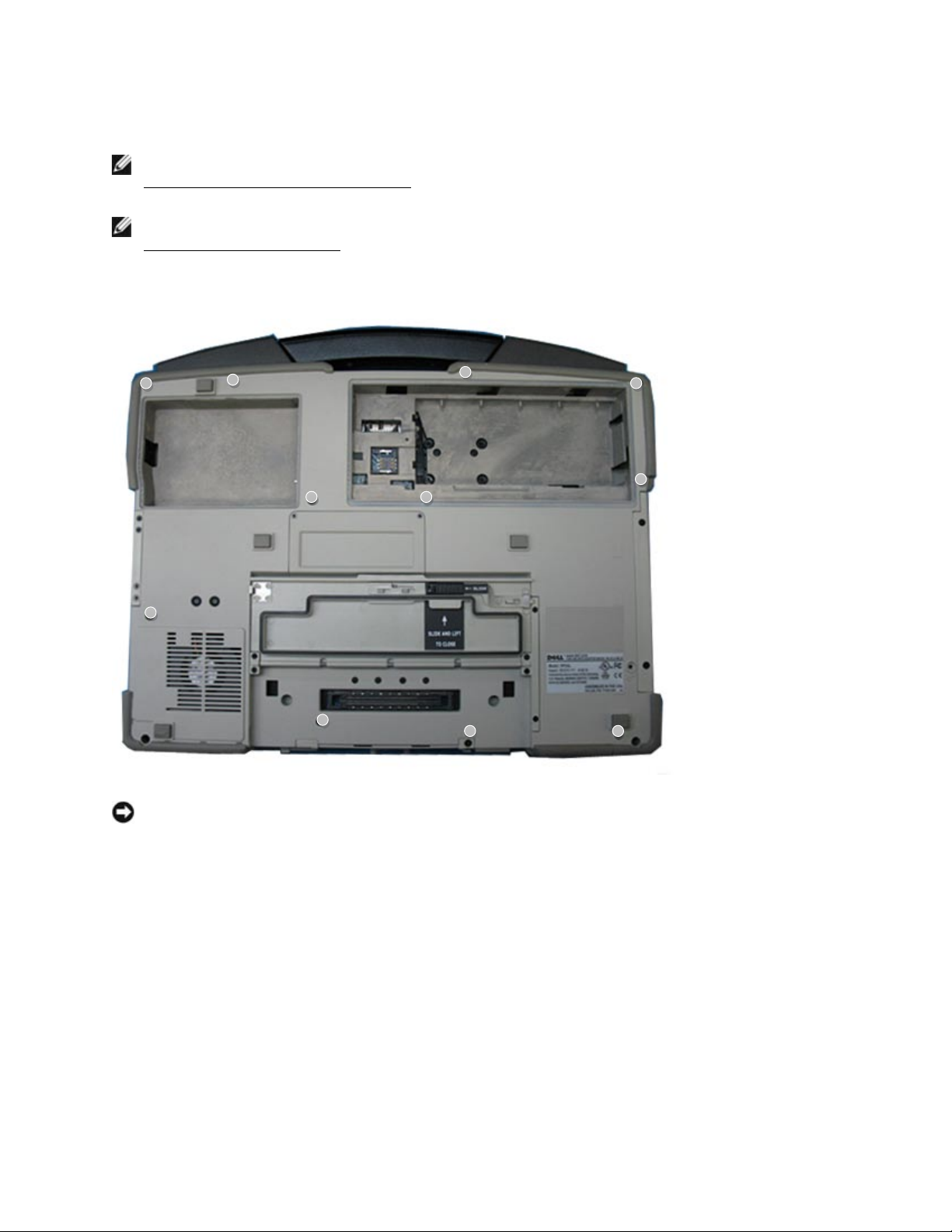
DellTM XFR D630 Fully Rugged Notebook Service Manual
Page 79 of 106
Revision A01
8. Turn the computer upside-down.
NOTE: Before proceeding, ensure that the main battery has been removed from the system (see
170H
Before Working Inside Your Computer
). One of the palm rest screws is located in the battery
bay.
NOTE: Open the Docking Door. Two of the palm rest screws are located beneath this door (see
171H
Removing the Docking Door
.)
9. Remove the 11 screws that secure the palm rest.
NOTICE: Carefully separate the palm rest from the base to avoid damage to the palm rest.
10. Turn the computer top-side up, slightly raise the palm rest, and then disconnect the touch-pad
cable connector from the system board.
11. Continue to raise the palm rest, and then disconnect the USB control cable from the system
board. Remove the palm rest.
Screws
(11)
Page 80
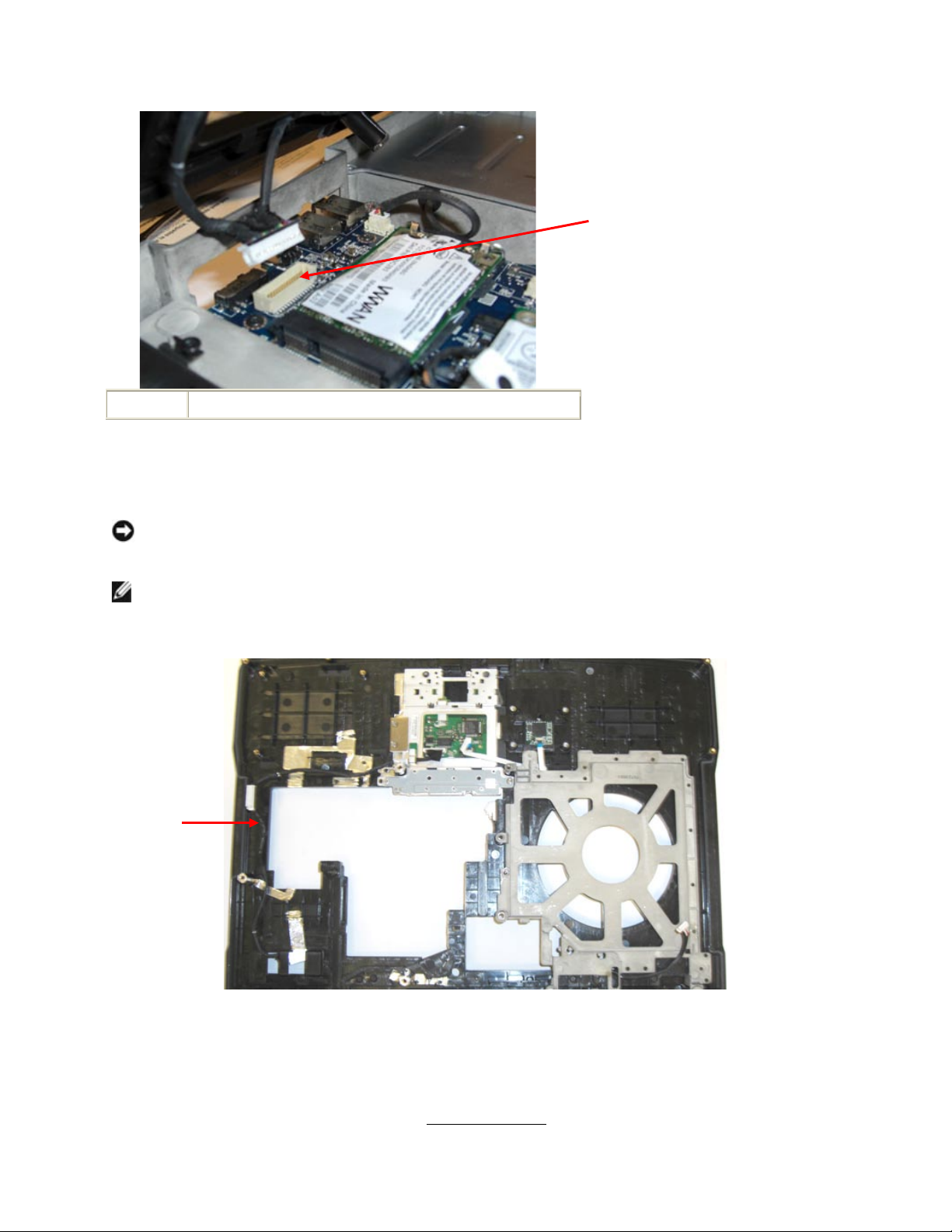
DellTM XFR D630 Fully Rugged Notebook Service Manual
Page 80 of 106
Revision A01
1
touch pad connector
14.2 Installing the Palm Rest
NOTICE: When reinstalling the palm rest, ensure that you reconnect the USB cable to the IO
dash board, and then reconnect the touch pad cable connector to the system board before
replacing the palm rest screws.
NOTE: If you are replacing the palm rest, remove the USB Control cable from the original palm
rest and route the same way in the new palm rest.
Underside of Palm Rest showing Touchpad Cable Route
1. Install the 5 top-side screws.
2. Turn the system over.
3. Install the 11 bottom screws.
4. Reconnect the coin-cell battery (see
172H
Coin-Cell Battery
).
Touch pad
connector
Touchpad
cable
Page 81

DellTM XFR D630 Fully Rugged Notebook Service Manual
Page 81 of 106
Revision A01
5. Replace the display assembly (see
173H
Installing the Display Assembly
).
6. Replace the keyboard (see
174H
Keyboards
).
7. Replace the XBay device (see
175H
XBay Devices
).
8. Replace the hinge cover (see
176H
Installing the Hinge Cover
).
9. Install the battery.
15 Wireless Local Area Network (WLAN)
Cards
If you ordered a WLAN card with your computer, the card is already installed.
CAUTION: Before you begin any of the procedures in this section, follow the safety
instructions in the XFR D630 Product Information Guide and in the XFR D630 User’s
Guide.
NOTICE: To avoid electrostatic discharge, ground yourself by using a wrist grounding strap or by
periodically touching an unpainted metal surface (such as a connector on the back of the
computer).
15.1 Removing the WLAN Card
1. Follow the procedures in
177H
Before You Begin
.
6. Remove the hinge cover (see
178H
Removing the Hinge Cover
).
3. Remove the keyboard (see
179H
Keyboards
).
4. Remove the display assembly (see
180H
Removing the Display Assembly
).
5. Remove the palm rest (see
181H
Removing the Palm Rest
).
NOTICE: To prevent damage to the connector, do not use tools to release the securing tabs.
6. If a WLAN card is not already installed, go to step 5. If you are replacing a WLAN card,
remove the existing card:
a. Disconnect the antenna cables from the card.
NOTE: The WLAN card may have two or three antenna connectors, depending on the type
of card you have.
b. Release the card by pushing the metal securing tabs away from the card until the card
pops up slightly.
c. Slide the card at a 45-degree angle out of its connector.
Page 82
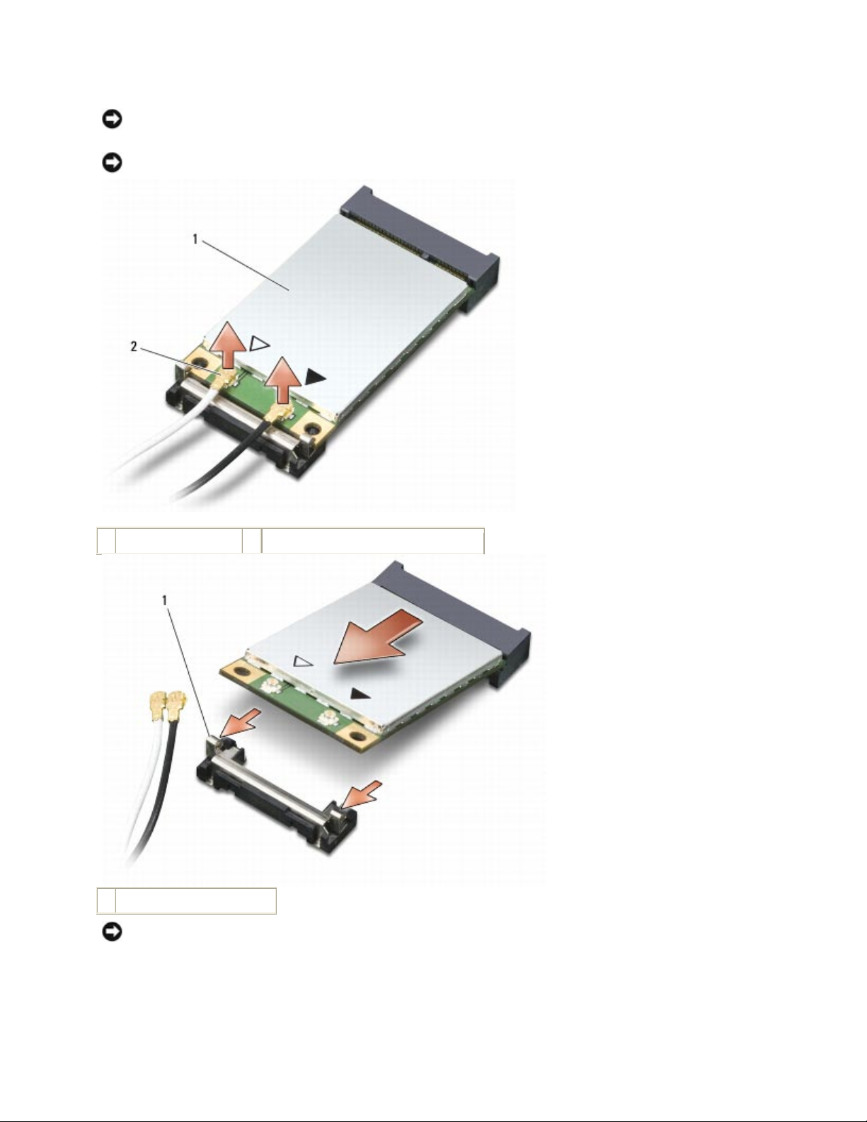
DellTM XFR D630 Fully Rugged Notebook Service Manual
Page 82 of 106
Revision A01
NOTICE: The card connector is keyed to ensure correct insertion. If you feel resistance, check
the connector and realign the card.
NOTICE: Do not insert a Mobile Broadband network (WWAN) card into the WLAN card connector.
1
WLAN card
2
antenna cable connectors
1
metal securing tabs (2)
NOTICE: To avoid damaging the WLAN card, never place cables on top of or under the card.
Page 83
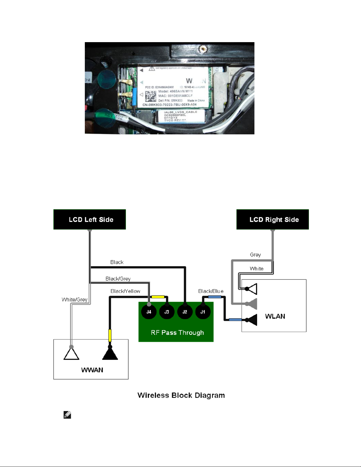
DellTM XFR D630 Fully Rugged Notebook Service Manual
Page 83 of 106
Revision A01
15.2 Installing the WLAN Card
1. Move any antenna cables out of the way to make space for the WLAN card.
2. Insert the WLAN card into the system board connector at a 45-degree angle, and press the
card into the metal securing tabs until you feel a click.
3. Connect the antenna cables to the WLAN card, ensuring that you route the cables correctly.
NOTE: For more specific information about which cable to connect to which connector,
see the documentation that came with your WLAN card.
Page 84

DellTM XFR D630 Fully Rugged Notebook Service Manual
Page 84 of 106
Revision A01
4. Replace the palm rest (see
182H
Installing the Palm Rest
).
5. Replace the display assembly (see
183H
Installing the Display Assembly
).
6. Replace the keyboard (see
184H
Keyboards
).
7. Replace the hinge cover (see
185H
Installing the Hinge Cover
).
16 Modem
CAUTION: Before you begin the following procedure, see the safety instructions in the
XFR D630 Product Information Guide and in the XFR D630 User’s Guide.
NOTICE: To avoid electrostatic discharge, ground yourself by using a wrist grounding strap or by
periodically touching an unpainted metal surface (such as a connector on the back of the
computer).
NOTICE: To avoid damaging the system board, you must remove the main battery before you
begin working inside the computer (see
186H
Before Working Inside Your Computer
).
16.1 Removing the Modem
1. Follow the instructions in
187H
Before You Begin
.
2. Remove the hinge cover (see
188H
Removing the Hinge Cover
).
3. Remove any installed media bay device (see
189H
XBay Devices
).
4. Remove the keyboard (see
190H
Keyboards
).
5. Remove the display assembly (see
191H
Removing the Display Assembly
).
6. Remove the palm rest (see
192H
Removing the Palm Rest
).
7. Remove the M2 x 3-mm screw that attaches the modem to the system board.
8. Pull up on the pull-tab to disconnect the modem from the connector on the system board.
Page 85
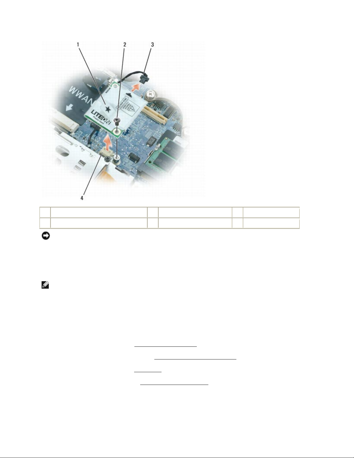
DellTM XFR D630 Fully Rugged Notebook Service Manual
Page 85 of 106
Revision A01
1
modem pull-tab
2
M2 x 3-mm screw
3
modem cable
4
system board connector
NOTICE: Do not disconnect the modem cable from the system board.
9. Disconnect the modem cable from the modem.
16.2 Installing the Modem
NOTE: When replacing the modem, it is easier to connect the modem cable to the modem before
you press the modem into the system board connector.
1. Connect the modem cable to the modem.
2. Connect the modem to the connector on the system board.
3. Install the M2 x 3mm screw that attaches the modem to the system board.
4. Replace the palm rest (see
193H
Installing the Palm Rest
).
5. Replace the display assembly (see
194H
Installing the Display Assembly
).
6. Replace the keyboard (see
195H
Keyboards
).
7. Replace the hinge cover (see
196H
Installing the Hinge Cover
).
17 Processor Thermal-Cooling Assembly
Page 86
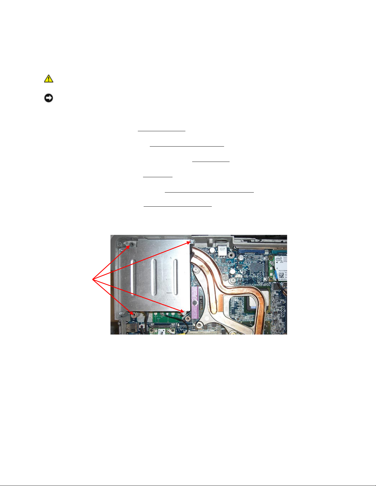
DellTM XFR D630 Fully Rugged Notebook Service Manual
Page 86 of 106
Revision A01
17.1 Removing the Processor Thermal-Cooling
Assembly
CAUTION: Before working inside your computer, follow the safety instructions in the
XFR D630 Product Information Guide and in the XFR D630 User’s Guide.
NOTICE: To avoid electrostatic discharge, ground yourself by using a wrist grounding strap or by
periodically touching an unpainted metal surface (such as a connector on the back of the
computer).
1. Follow the instructions in
197H
Before You Begin
.
2. Remove the hinge cover (see
198H
Removing the Hinge Cover
).
3. Remove any installed media bay device (see
199H
XBay Devices
).
4. Remove the keyboard (see
200H
Keyboards
).
5. Remove the display assembly (see
201H
Removing the Display Assembly
).
6. Remove the palm rest (see
202H
Removing the Palm Rest
).
7. Remove the fan cover by removing the 4 screws that secure the fan cover, and then lift the
fan cover out of the base.
8. Remove, in consecutive order, the three screws labeled "1" through "3," on the assembly.
Fan cover
screws (4)
Page 87
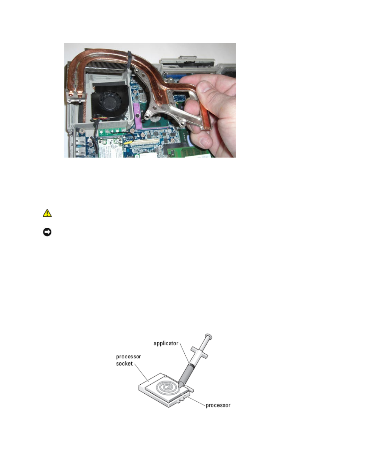
DellTM XFR D630 Fully Rugged Notebook Service Manual
Page 87 of 106
Revision A01
9. Lift the processor thermal-cooling assembly out of the computer.
17.2 Installing the Processor Thermal-Cooling
Assembly
CAUTION: Before working inside your computer, follow the safety instructions in the
XFR D630 Product Information Guide and in the XFR D630 User’s Guide.
NOTICE: To prevent static damage to components inside your computer, discharge static
electricity from your body before you touch any of your computer's electronic components. You
can do so by touching an unpainted metal surface.
1. If you are installing the original processor thermal-cooling assembly, skip to step 5; otherwise
continue to the next step.
2. Clean the heat sink. Use the cleaning pad provided with the processor thermal-cooling
assembly kit to clean the area between the 4 captive screws.
3. Apply the thermal grease. Follow the instructions provided with the processor thermalcooling assembly kit when using the syringe to apply thermal grease in a spiral pattern to the
processor thermal-cooling assembly.
4. Check the motherboard. Check the system board for any thermal pads on the large IC's next
to the processor. Remove any pads on top of the IC's. These came from the original
Page 88

DellTM XFR D630 Fully Rugged Notebook Service Manual
Page 88 of 106
Revision A01
processor thermal-cooling assembly. The new processor thermal-cooling assembly has new
pads already installed.
5. Install the heat sink. Place the processor thermal-cooling assembly on the system board.
6. Tighten in consecutive order the four captive screws, labeled "1" through "4," on the thermalcooling assembly.
7. Replace the fan cover and secure with the 4 screws.
8. Replace the palm rest (see
203H
Installing the Palm Rest
).
NOTE: Ensure that you reconnect the coin-cell battery (see
204H
Coin-Cell Battery
) before you replace
the keyboard.
9. Replace the display assembly (see
205H
Installing the Display Assembly
).
10. Replace the keyboard (see
206H
Keyboards
).
11. Replace the media bay device (see
207H
XBay Devices
).
12. Replace the hinge cover (see
208H
Installing the Hinge Cover
).
13. Replace the battery.
18 Processor
18.1 Removing the Processor
CAUTION: Before working inside your computer, follow the safety instructions in the
XFR D630 Product Information Guide and in the XFR D630 User’s Guide.
NOTICE: To avoid electrostatic discharge, ground yourself by using a wrist grounding strap or by
periodically touching an unpainted metal surface (such as a connector on the back of the
computer).
NOTICE: To prevent intermittent contact between the ZIF-socket cam screw and the processor
when removing or replacing the processor, press, to apply slight pressure to the center of the
processor while turning the cam screw.
NOTICE: To avoid damage to the processor, hold the screwdriver so that it is perpendicular to
the processor when turning the cam screw.
1. Follow the instructions in
209H
Before You Begin
.
2. Remove the hinge cover (see
210H
Removing the Hinge Cover
).
3. Remove any installed media bay device (see
211H
XBay Devices
).
4. Remove the keyboard (see
212H
Keyboards
).
5. Remove the display assembly (see
213H
Removing the Display Assembly
).
6. Remove the palm rest (see
214H
Removing the Palm Rest
).
Page 89
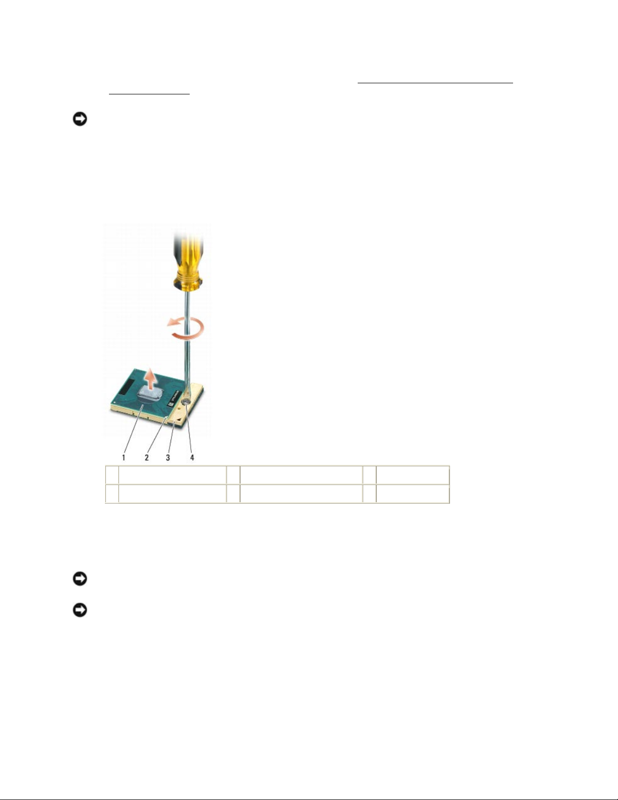
DellTM XFR D630 Fully Rugged Notebook Service Manual
Page 89 of 106
Revision A01
7. Remove the processor thermal-cooling assembly (see
215H
Removing the Processor Thermal-
Cooling Assembly
).
NOTICE: When removing the processor, pull it straight up. Be careful not to bend the pins on the
processor.
8. To loosen the ZIF socket, use a small, flat-blade screwdriver and rotate the ZIF-socket cam
screw counterclockwise until it comes to the cam stop.
The ZIF-socket cam screw secures the processor to the system board. Take note of the arrow
on the ZIF-socket cam screw.
1
processor
2
pin-1 corner of processor
3
ZIF socket
4
ZIF-socket cam screw
9. Use a processor extraction tool to remove the processor.
18.2 Installing the Processor
NOTICE: Ensure that the cam lock is in the fully open position before seating the processor.
Seating the processor properly in the ZIF socket does not require force.
NOTICE: A processor that is not properly seated can result in an intermittent connection or
permanent damage to the processor and ZIF socket.
1. Align the pin-1 corner of the processor so that it points to the triangle on the system board,
and insert the processor into the ZIF socket.
When the processor is correctly seated, all four corners are aligned at the same height. If one
or more corners of the processor are higher than the others, the processor is not seated
correctly.
Page 90
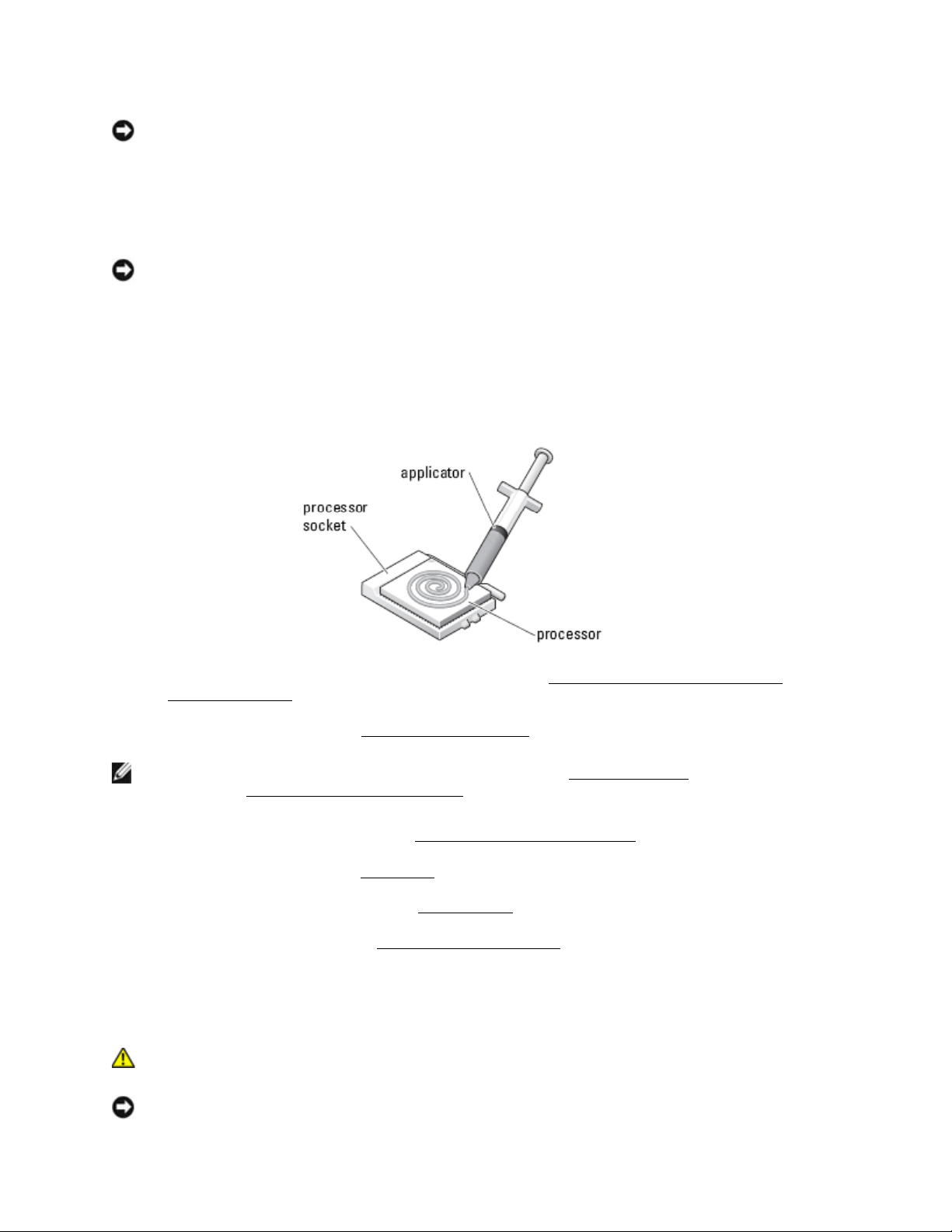
DellTM XFR D630 Fully Rugged Notebook Service Manual
Page 90 of 106
Revision A01
NOTICE: To prevent intermittent contact between the ZIF-socket cam screw and the processor
when removing or replacing the processor, press to apply slight pressure to the center of the
processor while turning the cam screw.
2. Tighten the ZIF socket by turning the cam screw clockwise to secure the processor to the
system board.
NOTICE: If you are installing the original processor, skip to step 5. To install a new processor,
continue with step 3.
3. Clean the heat sink. Use the cleaning pad provided with the processor kit to remove any old
thermal grease between the 3 captive screws.
4. Apply the thermal grease. Follow the instructions provided with the processor kit, to use the
syringe to apply thermal grease in a spiral pattern to the processor thermal-cooling assembly.
5. Replace the processor thermal-cooling assembly (see
216H
Installing the Processor Thermal-
Cooling Assembly
).
6. Replace the palm rest (see
217H
Installing the Palm Rest
).
NOTE: Ensure that you reconnect the coin-cell battery (see
218H
Coin-Cell Battery
) before you replace
the keyboard.
219H
Installing the Coin-Cell Battery
7. Replace the display assembly (see
220H
Installing the Display Assembly
).
8. Replace the keyboard (see
221H
Keyboards
).
9. Replace the media bay device (see
222H
XBay Devices
).
10. Replace the hinge cover (see
223H
Installing the Hinge Cover
).
11. Replace the battery.
19 PC Card Reader
CAUTION: Before working inside your computer, follow the safety instructions in the
XFR D630 Product Information Guide and in the XFR D630 User’s Guide.
NOTICE: To avoid electrostatic discharge, ground yourself by using a wrist grounding strap or by
Page 91
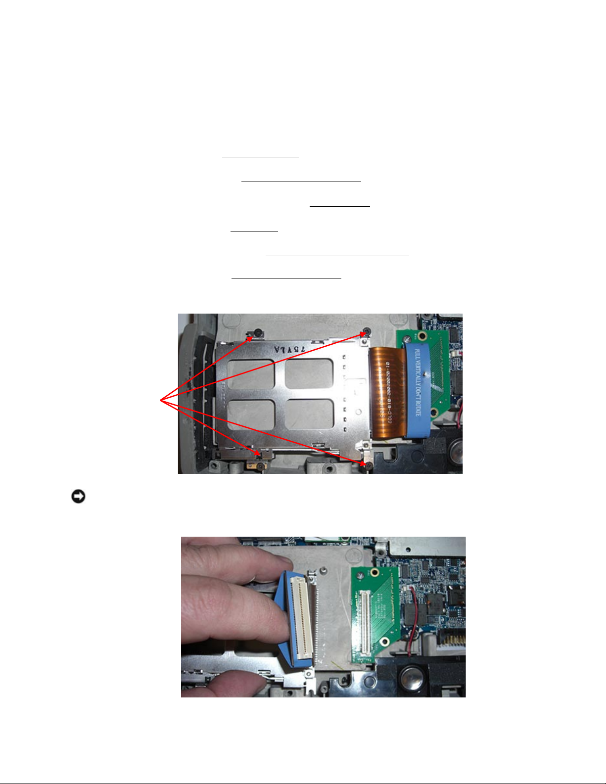
DellTM XFR D630 Fully Rugged Notebook Service Manual
Page 91 of 106
Revision A01
periodically touching an unpainted metal surface (such as a connector on the back of the
computer).
19.1 Removing the PC Card Cage
1. Follow the instructions in
224H
Before You Begin
.
2. Remove the hinge cover (see
225H
Removing the Hinge Cover
).
3. Remove any installed media bay device (see
226H
XBay Devices
).
4. Remove the keyboard (see
227H
Keyboards
).
5. Remove the display assembly (see
228H
Removing the Display Assembly
).
6. Remove the palm rest (see
229H
Removing the Palm Rest
).
7. Remove the four M2 x 3-mm screws that secure the PC Card reader to the computer.
NOTICE: To avoid damaging the PC Card reader connector, do not rotate or rock the connector
as you remove it. Use firm and even pressure to lift the pull-tab vertically.
8. Use the pull-tab to disconnect the PC Card reader connector from the PC Card interface board.
9. Remove the PC Card Reader assembly.
PC card reader
screws (4)
Page 92

DellTM XFR D630 Fully Rugged Notebook Service Manual
Page 92 of 106
Revision A01
NOTICE: If you are servicing the system board, RF Passthru board or bottom chassis, continue
with next steps to remove the PC Card interface board.
10. Remove the screw and then disconnect the interface board connector from the system board.
Remove the PC Card interface board.
19.2 Installing the PC Card Cage
NOTICE: If you removed the PC Card Reader only, skip to step 2. If you also removed the PC
Card interface board, start with step 1.
1. Install the PC Card interface. Connect the PC Card interface board to the system board and
secure with the screw to the bottom chassis.
2. Install the PC Card cage. Connect the PC Card Reader cable to the interface board. Install the
four M2x3-mm screws.
3. Replace the palm rest (see
230H
Installing the Palm Rest
).
NOTE: Ensure that you reconnect the coin-cell battery (see
231H
Coin-Cell Battery
) before you replace
the keyboard.
4. Replace the display assembly (see
232H
Installing the Display Assembly
).
5. Replace the keyboard (see
233H
Keyboards
).
6. Replace the media bay device (see
234H
XBay Devices
).
7. Replace the hinge cover (see
235H
Installing the Hinge Cover
).
8. Replace the battery.
20 Speaker
CAUTION: Before working inside your computer, follow the safety instructions in the
XFR D630 Product Information Guide and in the XFR D630 User’s Guide.
NOTICE: To avoid electrostatic discharge, ground yourself by using a wrist grounding strap or by
periodically touching an unpainted metal surface (such as a connector on the back of the
computer).
20.1 Removing the Speaker
1. Follow the instructions in
236H
Before You Begin
.
2. Remove the hinge cover (see
237H
Removing the Hinge Cover
).
3. Remove any installed media bay device (see
238H
XBay Devices
).
4. Remove the keyboard (see
239H
Keyboards
).
5. Remove the display assembly (see
240H
Removing the Display Assembly
).
Page 93
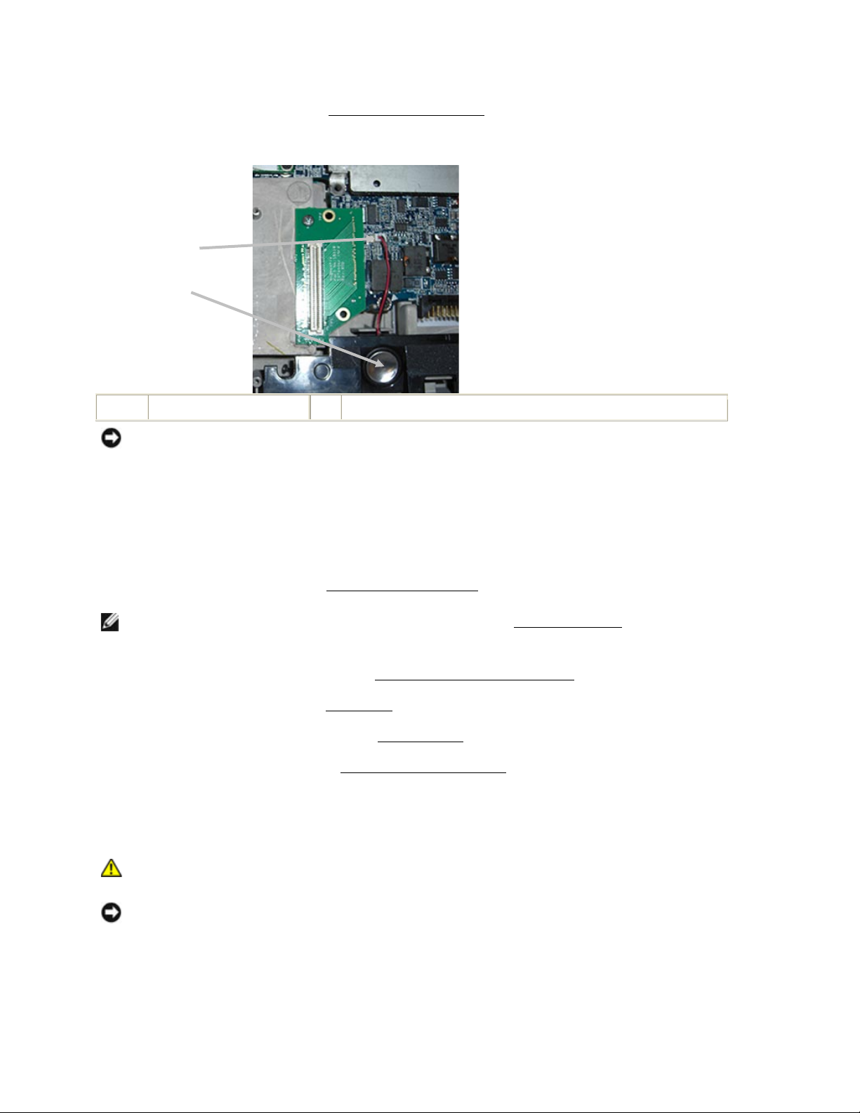
DellTM XFR D630 Fully Rugged Notebook Service Manual
Page 93 of 106
Revision A01
6. Remove the palm rest (see
241H
Removing the Palm Rest
).
7. Disconnect the speaker connector from the system board.
1
Speaker
2
Speaker connector
NOTICE: Handle the speakers with care to avoid damaging them.
8. Pull the speaker straight up and out of the base.
20.2 Installing the Speaker
1. Install the speaker in the base and attach the speaker cable to the system board.
2. Replace the palm rest (see
242H
Installing the Palm Rest
).
NOTE: Ensure that you reconnect the coin-cell battery (see
243H
Coin-Cell Battery
) before you replace
the keyboard.
3. Replace the display assembly (see
244H
Installing the Display Assembly
).
4. Replace the keyboard (see
245H
Keyboards
).
5. Replace the media bay device (see
246H
XBay Devices
).
6. Replace the hinge cover (see
247H
Installing the Hinge Cover
).
7. Replace the battery.
21 Fan
CAUTION: Before working inside your computer, follow the safety instructions in the
XFR D630 Product Information Guide and in the XFR D630 User’s Guide.
NOTICE: To avoid electrostatic discharge, ground yourself by using a wrist grounding strap or by
periodically touching an unpainted metal surface (such as a connector on the back of the
computer).
21.1 Removing the Fan
1
2
Page 94
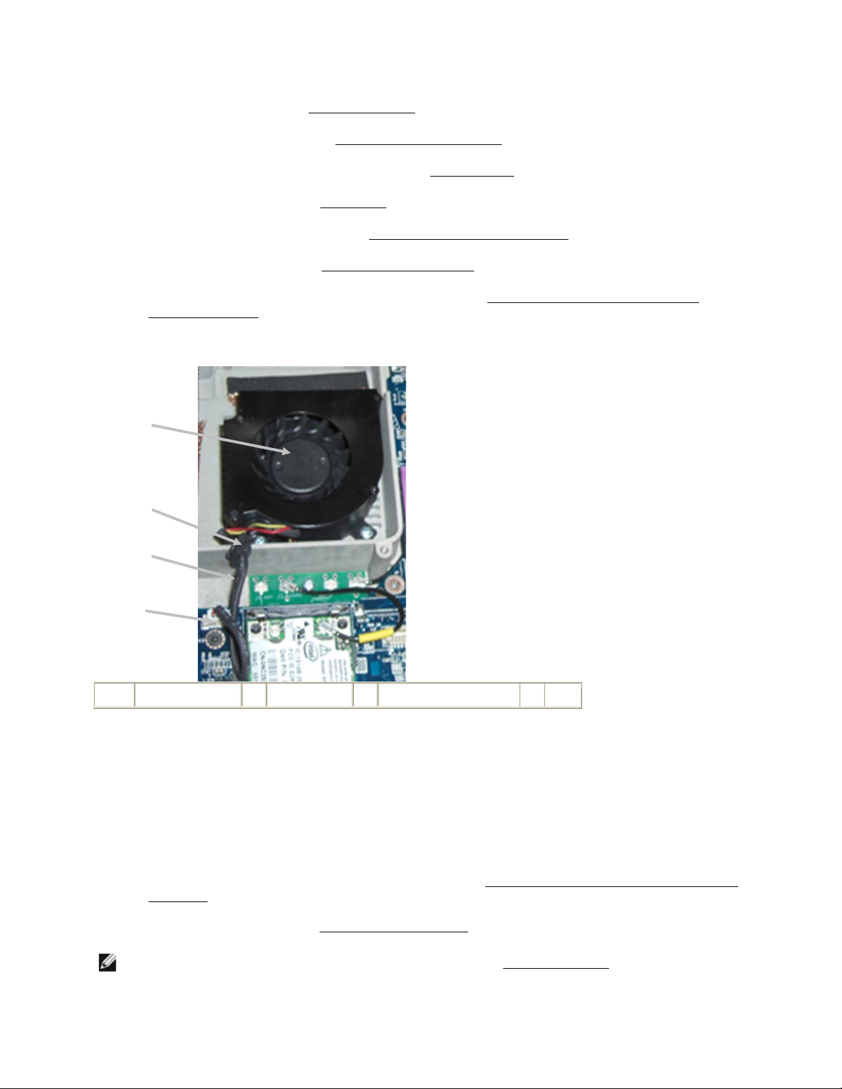
DellTM XFR D630 Fully Rugged Notebook Service Manual
Page 94 of 106
Revision A01
1. Follow the instructions in
248H
Before You Begin
.
2. Remove the hinge cover (see
249H
Removing the Hinge Cover
).
3. Remove any installed media bay device (see
250H
XBay Devices
).
4. Remove the keyboard (see
251H
Keyboards
).
5. Remove the display assembly (see
252H
Removing the Display Assembly
).
6. Remove the palm rest (see
253H
Removing the Palm Rest
).
7. Remove the processor thermal-cooling assembly (see
254H
Removing the Processor Thermal-
Cooling Assembly
).
8. Remove the 3 M3 x 4-mm screws that secure the fan to the base.
1
Fan connector
2
Fan cable
3
Fan cable grommet
4
Fan
9. Disconnect the fan cable from the system board and remove the fan.
21.2 Installing the Fan
1. Install the fan and attach to the base using the 3 M3 x 4-mm screws.
2. Attach the fan cable to the system board. Then attach the grommet on the fan cable to the
cage enclosure.
3. Replace the processor thermal-cooling assembly (see
255H
Installing the Processor Thermal-Cooling
Assembly
).
4. Replace the palm rest (see
256H
Installing the Palm Rest
).
NOTE: Ensure that you reconnect the coin-cell battery (see
257H
Coin-Cell Battery
) before you replace
the keyboard.
1
2
3
4
Page 95

DellTM XFR D630 Fully Rugged Notebook Service Manual
Page 95 of 106
Revision A01
5. Replace the display assembly (see
258H
Installing the Display Assembly
).
6. Replace the keyboard (see
259H
Keyboards
).
7. Replace the media bay device (see
260H
XBay Devices
).
8. Replace the hinge cover (see
261H
Installing the Hinge Cover
).
22 System Board
22.1 Removing the System Board
CAUTION: Before working inside your computer, follow the safety instructions in the
XFR D630 Product Information Guide and in the XFR D630 User’s Guide.
NOTICE: To avoid electrostatic discharge, ground yourself by using a wrist grounding strap or by
periodically touching an unpainted metal surface (such as a connector on the back of the
computer).
The system board's BIOS chip contains the Service Tag, which is also visible on a barcode label on the
bottom of the computer. The replacement kit for the system board includes a CD that provides a utility
for transferring the Service Tag to the replacement system board.
1. Follow the instructions in
262H
Before You Begin
.
2. Remove the hard disk drive (see
263H
Hard Drive
).
3. Remove the hinge cover (see
264H
Removing the Hinge Cover
).
4. Remove the keyboard (see
265H
Keyboards
).
5. Remove any installed media bay device (see
266H
XBay Devices
).
6. Remove the memory module(s) (see
267H
Memory
).
7. Remove the palm rest (see
268H
Removing the Palm Rest
).
8. Remove any installed wireless communications cards (see
269H
WWAN, FCM & SIM Cards
,
270H
Wireless
Local Area Network (WLAN) Cards
,
271H
Internal Card with Bluetooth® Wireless Technology
).
9. Remove the modem (see
272H
Removing the Modem
).
9. Remove the speaker (see
273H
Removing the Speaker
).
10. Remove the PC Card reader (see
274H
Removing the PC Card Cage
).
11. Remove any installed smart cards or smart card blanks from the smart card slot.
Page 96
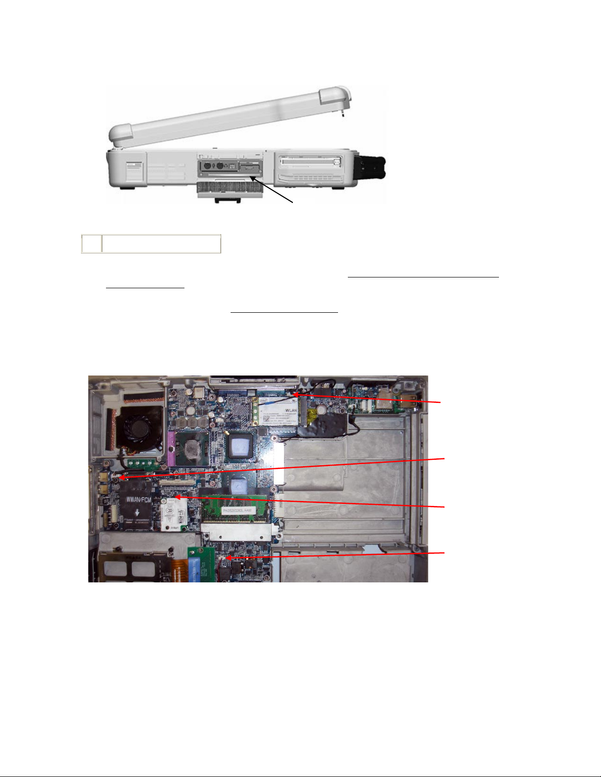
DellTM XFR D630 Fully Rugged Notebook Service Manual
Page 96 of 106
Revision A01
1
smart card slot
12. Remove the processor thermal-cooling assembly (see
275H
Removing the Processor Thermal-
Cooling Assembly
).
13. Remove the processor (see
276H
Removing the Processor
).
14. Disconnect the fan cable from the system board.
16. Disconnect the cables near the WLAN card and the modem connector from the system board.
17. Remove the four M2.5 x 5-mm screws (labeled with silver triangles on the system board).
WLAN
Connector
Modem
Connector
Fan
Connector
1
Speaker
Connector
Page 97
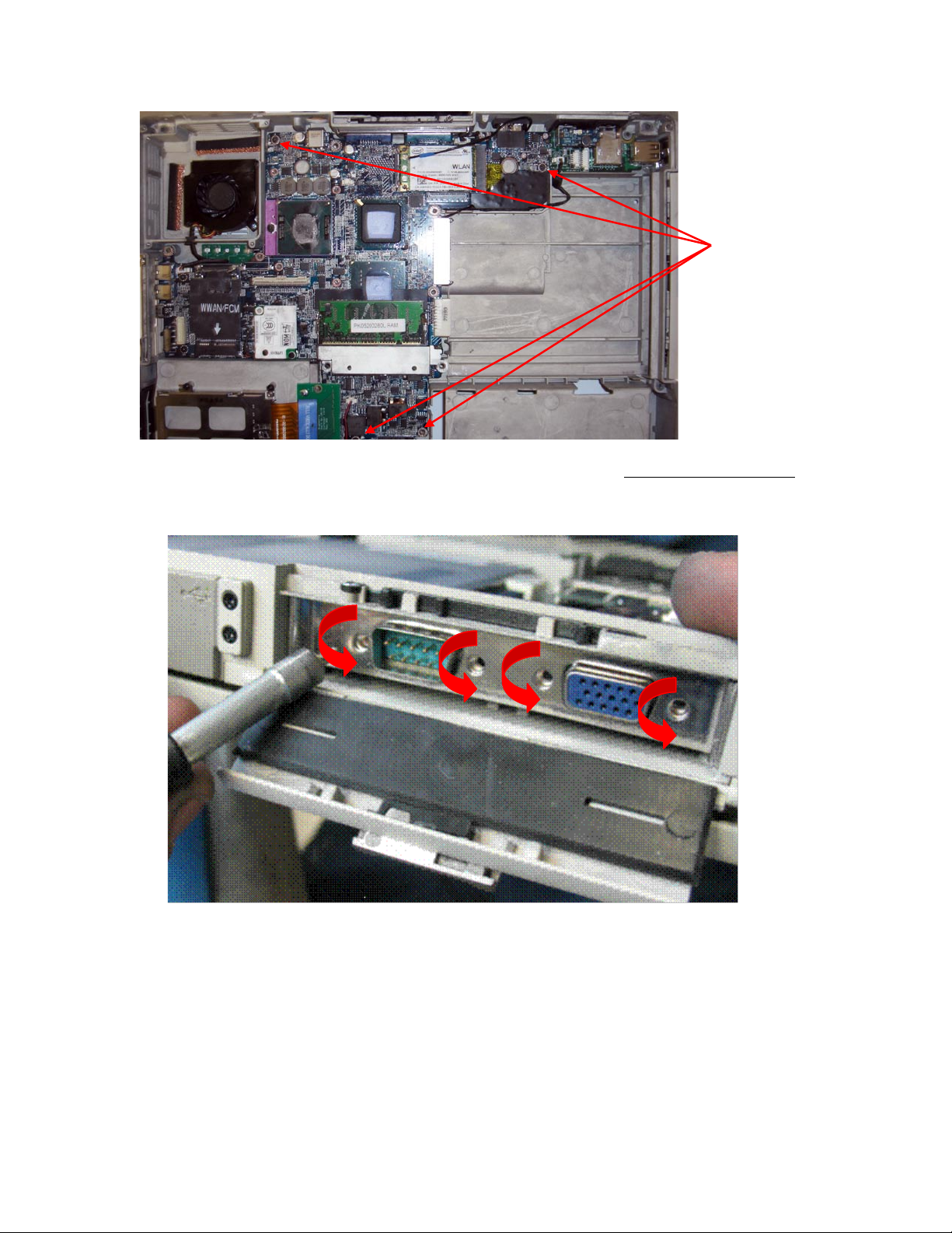
DellTM XFR D630 Fully Rugged Notebook Service Manual
Page 97 of 106
Revision A01
17. Remove the VGA Door from the rear panel of the notebook (see
277H
Removing the VGA Door
).
18. Remove the four 5-mm hex screws on the back of the computer.
19. To remove the system board:
a. Lift the lower corner near the speaker.
b. Grasp the system board next to the I/O dash board and lift up until the USB
connectors and the gasket on the right side clear the base.
c. While keeping the system board raised on the right side, push on the VGA connector
to clear the base. Pull the system board towards the front and right to clear the audio
ports and Wi-Fi switch on the left side, and lift out of the base.
System Board
Screw Locations
Page 98
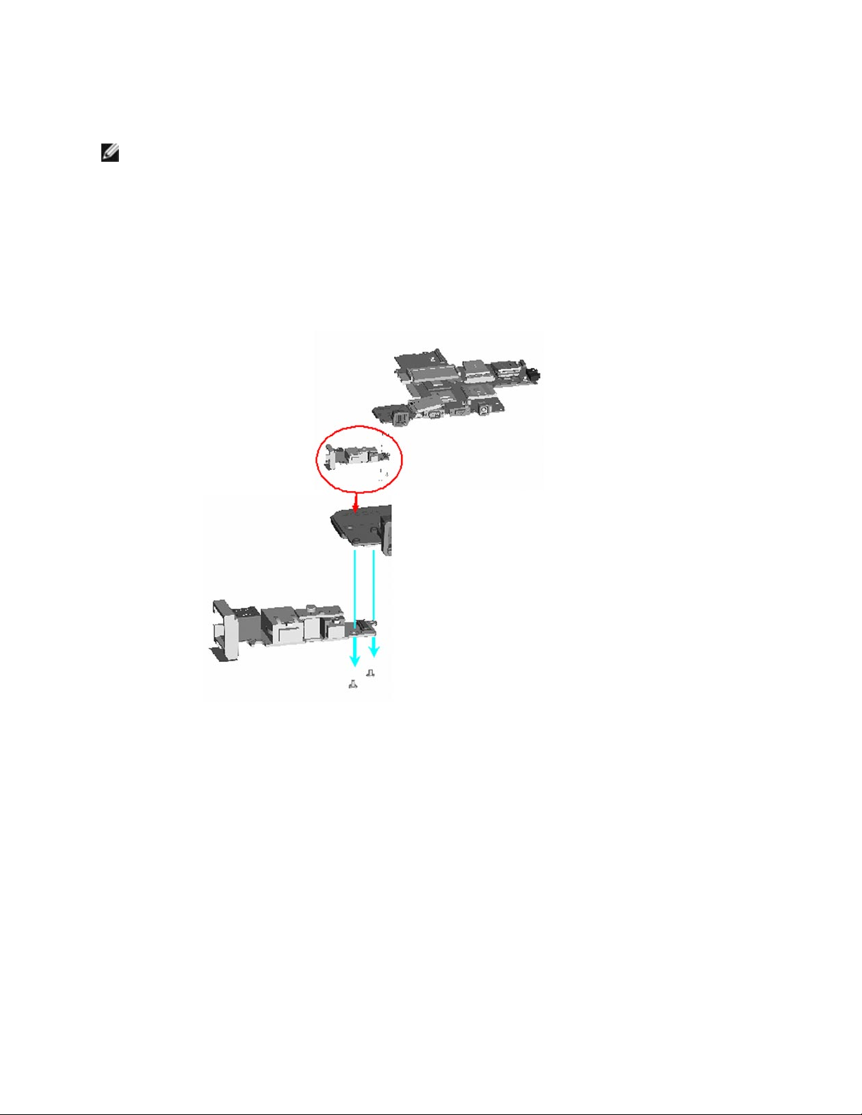
DellTM XFR D630 Fully Rugged Notebook Service Manual
Page 98 of 106
Revision A01
22.2 Installing the System Board
NOTE: If a new system board is installed, the kit includes a new system board and separate new
IO dash board, with instructions.
1. If you are installing a new system board, follow these instructions:
a. Remove the 2 M2 x 3-mm screws on the bottom of the original system board to
separate the system board from the IO dash board.
b. Use the 2 M2 x 3-mm screws just removed to secure the new IO dash board to the
new system board.
c. On the original system board, remove the 3 gaskets from the power port, rear USB
port and side USB port.
Page 99
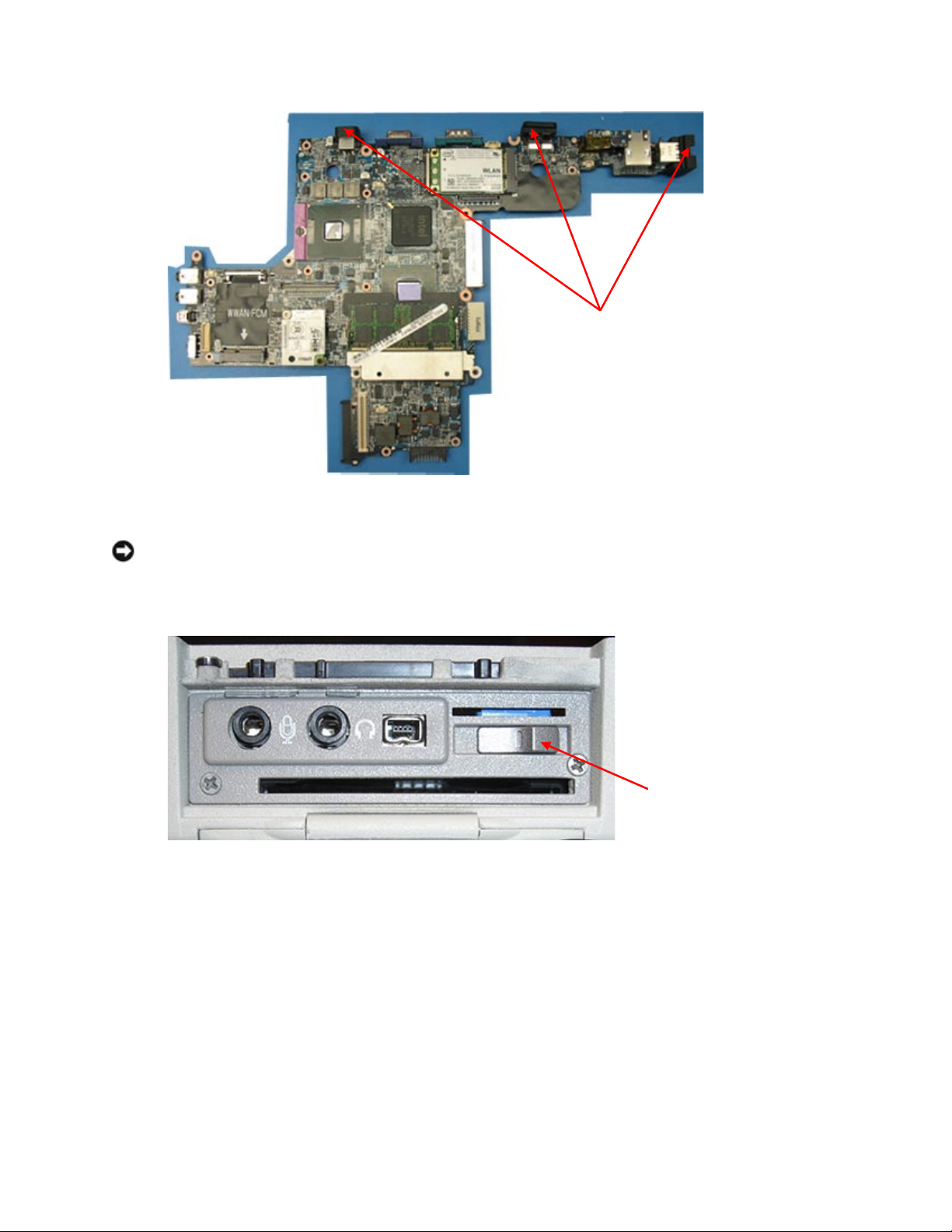
DellTM XFR D630 Fully Rugged Notebook Service Manual
Page 99 of 106
Revision A01
d. Install these 3 gaskets from the original system board onto the new system board.
NOTICE: When installing the system board, ensure that the fan cable antenna cables, and the 3
modem cables are clear of the system board before fitting it into the base, that the audio
connectors are properly seated, and that the tab for the wireless switch fits properly into the
detent on the slider mechanism before installing the system board into the base.
Once system board is partially seated, position the modem cables and the antenna cables by the RF
passthru board so they are not pinched.
Three gaskets
Wireless
Switch
Page 100
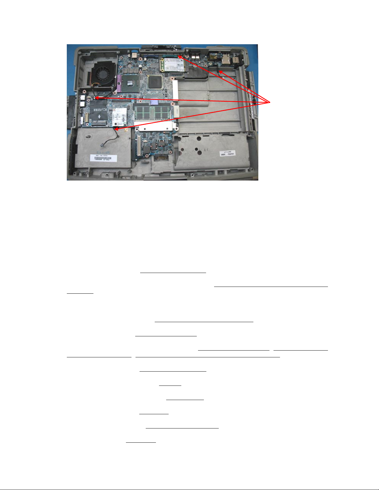
DellTM XFR D630 Fully Rugged Notebook Service Manual
Page 100 of 106
Revision A01
2. Complete the seating of the system board and again verify the cables are in the correct
positions, and the 3 gaskets for the power port, rear USB port and side USB port are correctly
positioned.
3. Secure the system board using the 4 M2.5 x 5-mm screws (labeled with silver triangles on the
system board).
4. Reconnect the cables near the WLAN card and the modem connector to the system board.
5. Reconnect the fan cable to the system board.
6. Install the processor (see
278H
Installing the Processor
).
7. Install the processor thermal-cooling assembly (see
279H
Installing the Processor Thermal-Cooling
Assembly
).
8. Install any smart cards or smart card blanks into the smart card slot.
9. Install the PC card reader (see
280H
Installing the PC Card Reader Cage
).
10. Install the speaker (see
281H
Installing the Speaker
).
11. Install any wireless communication cards (see
282H
WWAN, FCM & SIM Cards
,
283H
Wireless Local Area
Network (WLAN) Cards
,
284H
Internal Card with Bluetooth® Wireless Technology
).
12. Install the palm rest (see
285H
Installing the Palm Rest
).
13. Install the memory module (see
286H
Memory
).
14. Install any media bay devices (see
287H
XBay Devices
).
15. Install the keyboard (see
288H
Keyboards
).
16. Install the hinge cover (see
289H
Installing the Hinge Cover
).
17. Install the HDD (see
290H
Hard Drive
).
Ensure cables
are properly
routed.
 Loading...