

Page 1

Dell EMC
VxBlock™ and Vblock® Systems 240
Administration Guide
Document revision 1.4
January 2018
Page 2
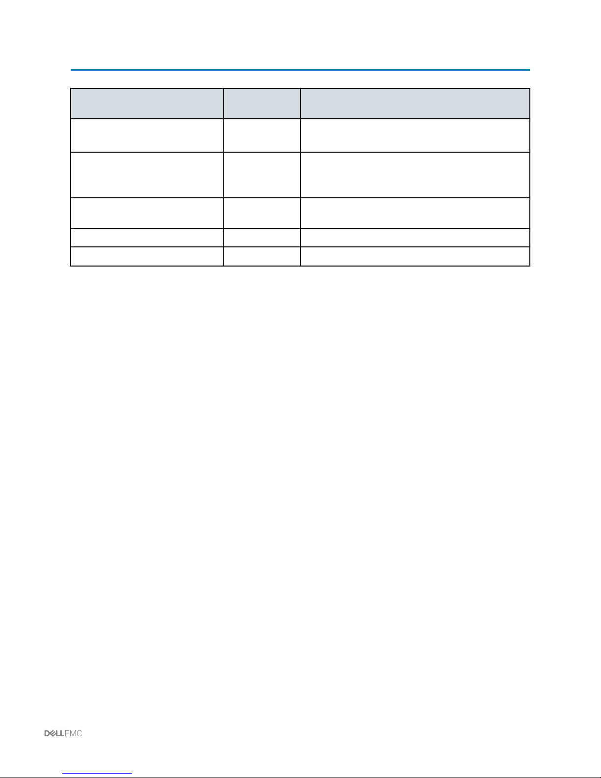
Revision history
Date Document
revision
January 2018 1.4 Added support for VMware vSphere 6.5.
December 2016 1.3 Added support for AMP-2 Cisco UCS M4 servers with
April 2016 1.2 Added support for VxBlock System 240, VMware
August 2015 1.1 IPI content added
August 2014 1.0 Initial release
Description of changes
Removed VMware vSphere 5.5.
VMware vSphere 5.5.
Removed VLAN 118 from topics.
vSphere 6.0, and Cisco UCS M4 servers.
Revision history | 2
Page 3

Contents
Introduction.................................................................................................................................................7
Intelligent Physical Infrastructure appliance........................................................................................... 8
Managing the AMP......................................................................................................................................9
Upgrading the Cisco UCS C220 Server on the Advanced Management Platform.................................9
Upgrading the Cisco UCS C2x0 Server (CIMC 2.x firmware).............................................................. 10
Configuring RAID devices.....................................................................................................................11
Backing up the AMP............................................................................................................................. 11
Creating a backup directory........................................................................................................... 11
Backing up AMP targets................................................................................................................ 12
Restoring a configuration file......................................................................................................... 13
Managing compute resources.................................................................................................................15
Modifying the time zone setting using CIMC........................................................................................ 15
Adding a syslog server using CIMC..................................................................................................... 15
Adding an SNMP server using CIMC................................................................................................... 15
Creating a vNIC using CIMC................................................................................................................ 17
Modifying vNIC properties using CIMC................................................................................................ 17
Adding virtualized servers: configuring vEthernet interfaces................................................................21
Adding virtualized servers: configuring static vEthernet interfaces on the Cisco Nexus
5548UP switches........................................................................................................................... 23
Virtual server interface numbering standards................................................................................ 25
Adding virtualized servers: modifying the Cisco UCS C220 Server components................................ 25
Enabling network interface virtualization on the converged network adapter................................ 26
Configuring the management vNICs .............................................................................................26
Configuring the vSphere vMotion vNICs........................................................................................26
Configuring the production vNICs..................................................................................................27
Configuring the Cisco Nexus 1000V Switch layer 3 Control vNICs............................................... 27
Configuring the NFS vNICs (Unified configuration only)................................................................28
Configuring the virtual HBAs..........................................................................................................28
Power cycling the host and verifying the host virtual Fibre Channel..............................................29
Adding virtualized servers: modifying boot options.............................................................................. 29
Configuring the boot table..............................................................................................................29
Mapping to the ISO file and rebooting the server.......................................................................... 29
Updating the boot order in BIOS....................................................................................................30
Adding a bare metal host: overview..................................................................................................... 30
Statically configuring vEthernet interfaces.....................................................................................31
Bare metal host static interface numbering standards...................................................................35
Dynamically configuring vEthernet interfaces................................................................................ 35
Bare metal host dynamically created interface numbering standards........................................... 39
Adding a bare metal host: modifying the Cisco UCS C220 rack server components.................... 39
Adding a bare metal host: modifying boot options.........................................................................41
Using the Cisco Trusted Platform Module............................................................................................42
Managing networking resources.............................................................................................................43
3 | Contents
Page 4

Creating VLANs and ports on the Cisco Nexus 5548UP Switch..........................................................43
Removing a VLAN from the Cisco Nexus series switches................................................................... 44
Configuring zones for storage.............................................................................................................. 45
Configuring Cisco Nexus 5000 Series NX-OS Adapter-FEX software.................................................46
Manually creating virtual Ethernet interfaces....................................................................................... 48
Managing virtual HBA interfaces on the Cisco UCS VIC 1225............................................................ 49
Creating virtual HBAs........................................................................................................................... 49
Viewing virtual HBA properties.............................................................................................................50
Modifying virtual HBA properties.......................................................................................................... 50
Upgrading the Cisco Nexus 3048 Switch software.............................................................................. 53
Downgrading Cisco Nexus series switch software...............................................................................57
Managing storage resources...................................................................................................................59
Logging on to a storage array.............................................................................................................. 59
Creating storage pools......................................................................................................................... 59
Expanding a storage pool.....................................................................................................................61
Monitoring a storage pool.....................................................................................................................62
Creating a boot LUN.............................................................................................................................62
Creating a data LUN.............................................................................................................................63
Expanding LUN capacity ..................................................................................................................... 64
Deleting a LUN..................................................................................................................................... 65
Creating a storage group......................................................................................................................65
Adding a host to a storage group......................................................................................................... 66
Adding a LUN to a storage group.........................................................................................................66
Monitoring a RAID group......................................................................................................................67
Using VMware EVC with Cisco UCS rack servers............................................................................... 67
Creating X-Blades.....................................................................................................................................69
Managing NFS...........................................................................................................................................70
Creating a file system on a storage array.............................................................................................70
Creating an NFS export on a storage array......................................................................................... 72
Mounting the NFS export..................................................................................................................... 73
Unmounting the NFS export.................................................................................................................73
Deleting the NFS Export.......................................................................................................................74
Managing CIFS..........................................................................................................................................75
Creating a CIFS file system..................................................................................................................75
Creating a CIFS share..........................................................................................................................76
Mapping the CIFS share...................................................................................................................... 77
Unmapping a CIFS share.....................................................................................................................78
Deleting a CIFS share.......................................................................................................................... 78
Managing VMware vSphere ESXi 6.x...................................................................................................... 80
Installing the latest VMware vSphere ESXi patch (vSphere 6.x)..........................................................80
Configuring advanced settings for VMware vSphere ESXi (vSphere 6.x)............................................81
Restoring default settings for VMware vSphere ESXi.......................................................................... 83
Hardening security on VMware vSphere ESXi hosts........................................................................... 83
Installing vCenter Server root certificates on Web Browser (vSphere 6.5).......................................... 83
Increasing VMFS datastore capacity ...................................................................................................84
Contents | 4
Page 5

Managing VMware vSphere virtual machines........................................................................................85
Increasing the disk timeout on Microsoft Windows virtual machines................................................... 85
Setting up Java and Internet Explorer on the management virtual machine........................................85
Managing VMware vCenter Single Sign-On for VMware vSphere 6.x..................................................87
VMware vCenter Single Sign-On overview.......................................................................................... 87
Unlocking and resetting the VMware vCenter Single Sign-On administrator password (VMware
vSphere 6.0).........................................................................................................................................87
Managing the lockout status of VMware vCenter Single Sign-On account (VMware vSphere 6.0)..... 87
Managing VMware vCenter Single Sign-On default password policies (VMware vSphere 6.0).......... 88
Managing VMware vCenter Single Sign-On lockout policies (VMware vSphere 6.0).......................... 88
Adding an Active Directory identity source to VMware vCenter Single Sign-On (VMware vSphere
6.0)....................................................................................................................................................... 88
Backing up or restoring the VMware external Platform Services Controller configuration (VMware
vSphere 6.0).........................................................................................................................................90
File-based backing up and restoring vCenter Server Applicance (vSphere 6.5)..................................90
Redirecting VMware vCenter Server to the secondary external Platform Services Controller
(VMware vSphere 6.0)......................................................................................................................... 90
Enabling fault tolerance for external Platform Services Controller (VMware vSphere 6.0).................. 91
Managing VMware vSphere ESXi 6.0...................................................................................................... 92
Configuring the persistent scratch location (vSphere 6.0)....................................................................92
Configuring the firewall on VMware ESXi hosts (vSphere 6.0)............................................................ 93
Configuring advanced settings for VMware ESXi hosts (vSphere 6.0) (AMP-2M4).............................93
Configuring NTP on VMware ESXi hosts (vSphere 6.0)...................................................................... 94
Configuring DNS on VMware ESXi hosts (vSphere 6.0) (AMP-2 M4)................................................. 94
Configuring VMware ESXi core dump collector service (vSphere 6.0)................................................ 95
Managing VMware VDS............................................................................................................................ 97
Managing licenses................................................................................................................................97
Provisioning a VMware VDS configuration...........................................................................................97
Modifying an existing distributed port group.................................................................................. 97
Creating a distributed port group................................................................................................... 99
Configuring a VMkernel interface...................................................................................................99
Associating VMware vSphere ESXi hosts to an existing VMware VDS.......................................101
Configuring jumbo frames on VMware VDS................................................................................ 102
Configuring jumbo frames on distributed port groups.................................................................. 102
Modifying class of service settings...............................................................................................103
Decommissioning VMware VDS components....................................................................................104
Deleting a distributed port group..................................................................................................104
Disassociating the VMware vSphere ESXi host.......................................................................... 106
Removing a VMware VDS............................................................................................................111
Backing up and restoring a VMware VDS data configuration.............................................................114
Exporting a backup of a VMware dvSwitch configuration............................................................ 114
Importing a backup of a dvSwitch configuration...........................................................................115
Restoring a backup of the dvSwitch configuration....................................................................... 115
VMware VDS basic troubleshooting................................................................................................... 116
Managing the Cisco Nexus 1000V Series Switch.................................................................................117
5 | Contents
Page 6

Managing licenses..............................................................................................................................117
Adding hosts.......................................................................................................................................117
Creating a port profile......................................................................................................................... 117
Modifying the uplink port profiles........................................................................................................ 118
Removing the uplink port profiles....................................................................................................... 119
Modifying vEthernet data port profiles................................................................................................120
Modifying the QoS settings ............................................................................................................... 122
Upgrading the VEM software............................................................................................................. 123
Troubleshooting the Cisco Nexus 1000V switch................................................................................ 123
Guidelines for backing up system configuration files........................................................................ 125
Backing up configuration files.............................................................................................................125
Backing up network devices running Cisco NX-OS software.............................................................125
Backing up network devices running Cisco IOS software.................................................................. 127
Backing up the VMware vCenter SQL Server database.................................................................... 129
Contents | 6
Page 7

Introduction
This document explains how to perform administrative tasks on the Converged System after it has been
installed.
In this document, the Vblock System and the VxBlock System are referred to as Converged System.
The target audience for this document includes those responsible for managing the Converged System,
including the system administrator and personnel responsible for remote management of the Converged
System. The document assumes that the person administering the Converged System:
Is familiar with VMware, storage technologies, and Cisco compute and networking technologies
•
Is familiar with Converged System concepts and terminology
•
Has Converged System troubleshooting skills
•
The Glossary provides terms, definitions, and acronyms.
7 | Introduction
Page 8

IPI Appliance
The IPI Appliance provides an intelligent gateway to gather information about power, thermals, security,
alerts, and all components in the physical infrastructure of each cabinet.
Vision Intelligent Operations uses SNMP to poll the status of the IPI Appliance and then passes the
results to VMware vCenter.
For cabinet-related operations such as adding users or cabinet access cards, refer to the VCE Intelligent
Physical Infrastructure Appliance User Manual.
Refer to the management release certification matrix (RCM) to identify the recommended firmware
version for your IPI Appliance. Contact Support with any questions.
Accessing the IPI Appliance
To access the IPI Appliance in a given cabinet, connect a laptop to the appropriate subnet and use a
browser to access the IPI Appliance.
The following default settings apply:
IP address: 192.168.0.253
•
Mask: 255.255.255.0
•
Gateway: 192.168.0.1
•
IPI Appliance | 8
Page 9

Managing the Advanced Management Platform
Upgrading the Cisco UCS C220 Server on the Advanced
Management Platform
Use this procedure to prepare the ISO for a remote upgrade using a Keyboard, Video, Mouse (KVM)
switch.
Before you begin
If you are upgrading a Cisco UCS C220 Server on the Advanced Management Platform:
1 Power off or migrate VMs on the host being upgraded before running the upgrade procedure.
Refer to the Cisco Host Upgrade Utility Release 1.4(4) Quick Start Guide.
2 Find the ISO file download for your server online and download it to a temporary location
accessible from the Cisco UCS C220 being upgraded.
About this task
If you are upgrading a Cisco UCS C220 Server on the AMP, you lose management access to the
Converged System. Verify that the AMP VMs come back up and specific application services restart for
database servers, the VMware vCenter server, and associated VUM servers.
Procedure
1 Use a web browser to navigate to the CIMC Manager software on the server that you are
upgrading.
a Type the CIMC IP address for the server in the address field of the browser.
b Type your username and password.
c From the toolbar, click Launch KVM Console.
d The access method for the virtual media depends on the version of the KVM console that you
are using. If the KVM Console window has a VM tab, select that tab, otherwise, select
Tools > Launch Virtual Media.
e Click Add Image and select the downloaded ISO file.
f In the Client View, select the checkbox in the Mapped column for the ISO file that you added
and then wait for mapping to complete. The KVM displays the progress in the Details
section.
g Verify the ISO file appears as a mapped remote device.
h Boot the server and press F6 when prompted to open the Boot Menu screen.
2 On the Boot Menu screen, select Cisco Virtual CD/DVD and press Enter. The server reboots
from the selected device.
3 When the server BIOS and CIMC firmware versions appear, at the Have you read the Cisco
EULA? prompt, type: Y
9 | Managing the Advanced Management Platform
Page 10

4 From the Host Upgrade menu, at the Enter Choice prompt, select all of the above.
5 After all upgrades are successful, select the appropriate CIMC settings to use during the reboot
from the Host Upgrade menu.
6 Select Reboot to retain the current settings of CIMC.
7 Verify that all VMs are powered up and have access to the VMware vCenter.
Upgrading the Cisco UCS C2x0 Server (CIMC 2.x firmware)
Perform a remote upgrade using KVM with CIMC for the Cisco UCS C2x0 Server firmware.
About this task
This topic is applicable to servers running CIMC 2.x firmware.
Before you begin
Migrate the VMs off the host that is being upgraded. Find the ISO file download for your server online and
download it to a temporary location accessible from the Cisco UCS C2x0 Server being upgraded.
For additional information, refer to the Cisco Host Upgrade Utility User Guide.
Procedure
1 Use a web browser to navigate to the CIMC Manager software on the server that you are
upgrading.
a Type the CIMC IP address for the server in the address field of the browser.
b Type your username and password.
c From the toolbar, click Launch KVM Console.
d The access method for the virtual media depends on the version of the KVM console that you
are using. If the KVM Console window has a Virtual Media (VM) tab, select that tab.
Otherwise, select Tools > Launch Virtual Media.
e Click Add Image and select the downloaded ISO file.
f In the Client Viewin the Mapped column select the ISO file that you added and then wait for
mapping to complete.
g Verify the ISO file appears as a mapped remote device.
h Boot the server and press F6 when prompted to open the Boot Menu screen.
2 On the Boot Menu screen, select Cisco vKVM-Mapped vDVD1.22 and press Enter.
3 When the server BIOS and CIMC firmware versions appear, at the Have you read the Cisco
EULA?, select I agree
4 From the Host Upgrade menu, select Update All.
Managing the Advanced Management Platform | 10
Page 11

5 At the Confirmation screen, select Yes.
6 From the Confirmation screen for the BIOS update, select Yes.
7 After reboot is complete, verify that the VMware vSphere ESXi host is accessible to the AMP-2
vCenter Server instance.
Configuring RAID devices
Use this procedure to set up RAID devices on the AMP-2P Cisco UCS C2x0 server that has an LSI
MegaRAID controller card.
Before you begin
The utility requires Java and Flash.
About this task
Create two RAID devices for use as data stores.
•
Perform this procedure on the AMP-2P Cisco UCS C2x0 server.
•
Procedure
1 Log on to CIMC of the Cisco UCS AMP server as admin.
2 Navigate to Storage > Cisco 12G SAS Modular Raid > Controller Info.
3 Select Create Virtual Drive from Unused Physical Drives.
If there are pre-existing virtual drives, delete them and proceed.
4 Create one RAID-1 virtual drive using 49 percent of the available capacity of all unused physical
drives. Use the name RAID1_MI01.
A slight variation in size allows you to differentiate the devices if you perform a query
through a script. The variation in size also allows for capacity usage by lifeboat files on
secondary data store.
5 Select Create Virtual Drive from an Existing Virtual Drive Group.
6 Create one RAID-1 virtual drive using the remaining available capacity of all physical drives. Use
the name RAID1_MI02.
Backing up the AMP
Creating a backup directory
Use this procedure to build the environment to support the back up of Converged System configuration
files for change management and recovery.
11 | Managing the Advanced Management Platform
Page 12

About this task
This process is required to support the recovery of the Cisco network device configurations in the
Converged System.
Establish a process to perform network device configuration backups and that you place the repository on
the AMP VM that hosts the fabric manager service.
Before you begin
Access a copy of the PuTTY software used to verify device connectivity and login credentials
•
Access a copy of the TFTP server software that provides a method to accept a remote copy of
•
device configuration files
Identify the VM within the AMP deployment where the repository is to be created
•
Monitor disk storage resources to prevent overuse issues and data unavailability
•
Procedure
1 To create the backup directory, type: mkdir drive :\Cisco.
Use the the D:\ drive. However, if the D:\ drive is not available, use the C:\ drive. This drive is
referenced throughout these instructions.
2 Create the named devices and data subdirectories. It is recommended that you create one set of
empty subdirectories and then copy them to the other device directories. The directory names are
the major model numbers with 00 substituted for the last two digits of the device model.
The list of device models is provided as an example. Create only the entries needed to
support the Converged System being deployed.
3 Install the TFTP server.
4 To configure the TFTP server, in the home directory is the location created above drive :
\Cisco, restrict read/write access to the IP range of devices sending configuration files.
5 To verify the procedure, check the directories and make sure entries from the network devices
exist.
What to do next
Initiate network device configuration backups.
Backing up AMP targets
Back up targets in the AMP servers.
About this task
The AMP servers are:
VMware vCenter Server, Web Server, and Inventory Service
•
Managing the Advanced Management Platform | 12
Page 13

VMware vCenter SQL database (if VMware vSphere vCenter has been deployed on Windows)
•
VMware vCenter Update Manager
•
Platform Services Controller (VMware vSphere 6.0)
•
Element Manager
•
Other VMs identified as part of the Core or Optional workloads to manage the Converged
•
System.
Recommended backup schedule:
Perform daily backups of all VMs at 7 A.M. and 7 P.M.
•
Perform daily backups of the VMware vCenter SQL Server database every four hours. This
•
coincides with server daily backups at 3, 7, 11 A.M. and 3, 7, 11 P.M.
Set the retention value set to 35 days.
•
Disk storage resources should be monitored to prevent overuse issues and data
unavailability.
To ensure the ability to recover data, store the AMP server backups on backup media. Otherwise, you will
be unable, or severely limited, in the ability to manage or recover the Converged System.
You must perform configuration backups for these devices:
Cisco management switches
•
Cisco network switches
•
Storage platform
•
To back up targets in AMP, refer to the documentation provided with the backup tool vendor.
Restoring a configuration file
Restore a network or storage device configuration file in the event of failure, corruption, or other data loss
event.
About this task
Follow the vendor recommended restore processes for the device.
Before you begin
Verify that local or remote connectivity exists to the impacted device.
•
Access the configuration file needed to restore operational status.
•
Obtain a method to transfer the configuration file from the source location to the impacted device
•
whether it be FTP, or copy and paste.
13 | Managing the Advanced Management Platform
Page 14

Procedure
To restore a configuration file, refer to the documentation provided with the vendor to restore the device.
Managing the Advanced Management Platform | 14
Page 15

Managing compute resources
Modifying the time zone setting using CIMC
In the Server Summary window of the CIMC, the Current Time field shows the current date and time,
that is retrieved from the server BIOS.
Procedure
1 Reboot the server and press the F2 key when prompted to access the BIOS configuration menu.
2 Select the BIOS configuration tab and change the date and/or time.
Adding a syslog server using CIMC
When you add a syslog server, logs are sent to the server to facilitate reporting alerts and
troubleshooting.
Before you begin
Before performing this task, a syslog server must be deployed and accessible.
About this task
Use the syslog server to facilitate the reporting of alerts and to help troubleshoot.
Procedure
1 From the Admin tab within CIMC, click CIMC Log.
2 From the CIMC Log window, select the Logging Controls tab.
3 In the Remote Syslog Server 1 section, click Enabled.
4 In the IP Address field, type the IP address of the syslog server on which the CIMC log should be
stored.
5 Verify that logs are being received on the syslog server.
6 To disable the logging of alerts, in the RemoteSyslogServer 1 section, click disabled.
Adding an SNMP server using CIMC
This procedure describes how to add an Simple Network Management Protocol (SNMP) server.
Before you begin
You must log on with admin privileges to perform this task.
15 | Managing compute resources
Page 16

About this task
Use an SNMP server to monitor, send alerts and reports, and to help troubleshoot. SNMP v3 is
recommended as the most secure option in using the SNMP protocol.
Procedure
1 In the Navigation window in CIMC, select the Admin tab.
2 On the Admin tab, click Communications Services.
3 In the Communications Services window, select the SNMP tab.
4 In the SNMP Properties area, edit the following fields:
—
Enabled check box: Check this box to send SNMP traps to the designated host.
—
SNMP Port field: This field displays the port that the server uses to communicate with the
SNMP host. This value cannot be changed.
—
Access Community String field: Type the default SNMP v1 or v2c community name or
SNMP v3 username that CIMC includes on any trap messages it sends to the SNMP host.
The name can include up to 18 characters.
—
System Contact field: Type the name of the person responsible for the SNMP
implementation. This name or information can include up to 254 characters, such as an email
address or a name and telephone number.
—
System Location field: Type the location of the host on which the SNMP agent (server) runs.
The location can include up to 254 characters.
5 In the SNMP Users area, edit the following properties:
—
Add button: Select an available row in the table then click Add to add a new SNMP user.
—
ID column: Displays the system-assigned identifier for the SNMP user.
—
Name column: Type the SNMP user name.
—
Auth Type column: Type the user authentication type.
—
Privacy Type column: Type the user privacy type.
6 In the Common Trap Destination Settings area, complete the following fields:
—
Trap Community String field: Type the name of the SNMP community group to which trap
information should be sent.
—
SNMP Version drop-down list: Select the SNMP version used for the trap.
—
Type field: If you select V2c for the version, select the type of trap to send.
Managing compute resources | 16
Page 17

7 In the Trap Destinations area, complete the following fields:
—
ID column: Type the trap destination ID. This value cannot be modified.
—
Enabled column: For each SNMP trap destination that you want to use, check the associated
box in this column.
—
Trap Destination IP Address column: Type the IP address to which SNMP trap information
is sent.
8 Click Save Changes.
Creating a vNIC using CIMC
Use the following steps to create a virtual network interface card (vNIC) using CIMC.
Procedure
1 On the Navigation pane, select the Server tab.
2 On the Server tab, click Inventory.
3 On the Inventory pane, select the Network > Adapters tab.
4 In the Adapter Cards area, select the adapter card.
If the server is powered on, the resources of the selected adapter card appear in the tabbed
menu below the Adapter > Cards area.
5 In the tabbed menu below the Adapter Cards area, select the vNICs tab.
6 In the Host Ethernet Interface area, perform one of these actions:
Option Description
To create a vNIC using default configuration settings... Click Add.
To create a vNIC using the same configuration settings as an existing
vNIC...
Select that vNIC and click Clone.
7 In the Add vNIC dialog box, enter a name for the vNIC in the Name entry box.
8 Click Add vNIC.
Modifying vNIC properties using CIMC
Use the following steps to modify vNIC properties using CIMC.
Procedure
1 On the Navigation pane, select the Server tab.
2 On the Server tab, click Inventory.
3 On the Inventory pane, select the Network > Adapters tab.
17 | Managing compute resources
Page 18

4 In the Adapter Cards area, select the adapter card.
If the server is powered on, the resources of the selected adapter card appear in the tabbed
menu below the Adapter Cards area.
5 In the tabbed menu below the Adapter Cards area, select the vNICs tab.
6 In the Host Ethernet Interfaces area, select a vNIC from the table.
7 Click Properties to open the vNIC Properties dialog box.
Managing compute resources | 18
Page 19

8 You can update any of the fields in the following areas. When you are finished, click Save
Changes.
General Area
Description
Field name
Name User-defined name for the vNIC. Once you create the vNIC, the name cannot be
changed.
MTU Maximum transmission unit, or packet size, that this vNIC accepts, between 1500 and
9000.
Uplink Port Uplink port associated with this vNIC. All traffic for this vNIC goes through this uplink
port.
MAC Address MAC address associated with the vNIC. To let the adapter select an available MAC
address from its internal pool, select Auto. To specify an address, click the second
radio button and enter the MAC address in the corresponding field.
Class of Service Class of service (CoS) to associate with traffic from this vNIC, ranging between 0 and
6, with 0 as the lowest priority and 6 as the highest priority.
Trust Host CoS Check this box if you want the vNIC to use the CoS provided by the host operating
system.
PCI Order Order in which this vNIC will be used.
To allow the system to set the order, select Any. To specify an order, select the
second radio button and enter an integer between 0 and 99.
Default VLAN If there is no default VLAN for this vNIC, click None. Otherwise, click the second radio
button and enter a VLAN ID between 1 and 4094.
VLAN Mode To use VLAN trunking, select TRUNK. Otherwise, select ACCESS.
Rate Limit To provide the vNIC with an unlimited data rate, select OFF. Otherwise, click the
second radio button and enter a rate limit between 1 and 10,000 Mbps.
Enable PXE Boot Check this box if the vNIC can perform a Preboot eXecution Environment (PXE) boot.
Ethernet Interrupt Area
Field name Description
Interrupt Count Number of interrupt resources, between 1 and 514, to allocate. In general, this value
should equal the number of completion queue resources.
Coalescing Time Time between interrupts or the idle period before an interrupt is sent. Enter a value
between 1 and 65535. To turn off interrupt coalescing, enter 0 (zero).
Coalescing Type Select MIN to make the system wait for the time specified in the Coalescing Time field
before sending another interrupt event.
Select IDLE to make the system send an interrupt after no activity occurs as least as
long as the time specified in the Coalescing Time field.
Interrupt Mode Driver interrupt mode. Choose one of the following:
—
MSI-X: Message Signaled Interrupts (MSI) with the optional extension. This is the
recommended option.
—
MSI: MSI only.
—
INTx: PCI INTx interrupts.
19 | Managing compute resources
Page 20
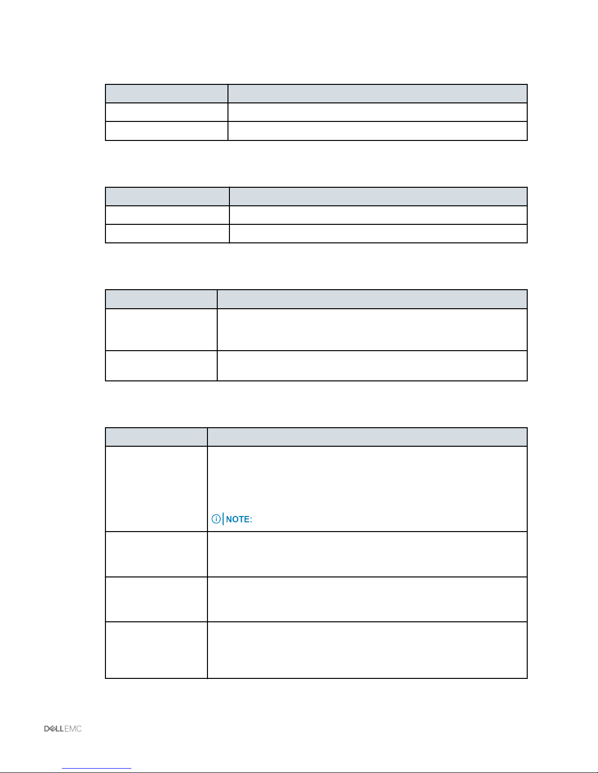
Ethernet Receive Queue Area
Field name Description
Receive Queue Count Number of receive queue resources to allocate, between 1 and 256.
Receive Queue Ring Size Number of descriptors in each receive queue, between 64 and 4096.
Ethernet Transmit Queue Area
Field name Description
Transmit Queue Count Number of transmit queue resources to allocate, between 1 and 256.
Transmit Queue Ring Size Number of descriptors in each transmit queue, between 64 and 4096.
Completion Queue Area
Field name Description
Completion Queue
Count
Completion Queue Ring
Size
Number of completion queue resources to allocate. In general, the number
should equal the number of transmit queue resources, plus the number of
receive queue resources. Enter an integer between 1 and 512.
Number of descriptors in each completion queue. This value cannot be
changed.
TCP Offload Area
Field name Description
Enable TCP
Segmentation Offload
Enable TCP Rx
Offload Checksum
Validation
Enable TCP Tx Offload
Checksum Generation
If this option is selected, the CPU sends large TCP packets to the hardware to
be segmented. This option might reduce CPU overhead and increase
throughput rate.
If this option is not selected, the CPU segments large packets.
If this option is selected, the CPU sends all packet checksums to the hardware
for validation. This option might reduce CPU overhead.
If this option is not selected, the CPU validates all packet checksums.
If this option is selected, the CPU sends all packets to the hardware so that the
checksum can be calculated. This option might reduce CPU overhead.
If this option is not selected, the CPU calculates all packet checksums.
This option is also known as Large Send Offload (LSO).
Enable Large Receive If this option is selected, the hardware reassembles all segmented packets
Receive Side Scaling Area
before sending them to the CPU. This option might reduce CPU utilization and
increase inbound throughput.
If this option is not selected, the CPU processes all large packets.
Managing compute resources | 20
Page 21

Field name Description
Enable TCP
Receive Side
Scaling
Enable IPv4 RSS If this option is selected, RSS is enabled on IPv4 networks.
Enable TCP-IPv4
RSS
Enable IPv6 RSS If this option is selected, RSS is enabled on IPv6 networks.
Enable TCP-IPv6
RSS
Enable IPv6
Extension RSS
Enable TCP-IPv6
Extension RSS
RSS distributes network receive processing across multiple CPUs in
multiprocessor systems.
If this option is selected, network receive processing is shared across processors
whenever possible.
If this option is not selected, network receive processing is handled by a single
processor, even if additional processors are available.
If this option is not selected, RSS is not enabled on IPv4 networks.
If this option is selected, RSS is enabled for TCP transmissions on IPv4 networks.
If this option is not selected, RSS is not enabled for TCP transmissions on IPv4
networks.
If this option is not selected, RSS is not enabled on IPv6 networks.
If this option is selected, RSS is enabled for TCP transmissions on IPv6 networks.
If this option is not selected, RSS is not enabled for TCP transmissions on IPv6
networks.
If this option is selected, RSS is enabled forIPv6 extensions.
If this option is not selected, RSS is not enabled for IPv6 extensions.
If this option is selected, RSS is enabled for TCP transmissions on IPv6 networks.
If this option is not selected, RSS is not enabled for TCP transmissions on IPv6
networks.
Adding virtualized servers: configuring vEthernet interfaces
With the Cisco NX-OS Adapter-FEX feature, there are two ways to logically configure the Cisco Nexus
5548UP Switches virtual Ethernet (vEthernet) interfaces for connectivity to the servers.
Static vEthernet creation of the Cisco Nexus 5548UP Switches is the standard for virtual servers.
•
Cisco Nexus 5548UP Switches on the Converged System are configured similarly and conform to
standards, which helps with identification and troubleshooting. Valid interface IDs should be less
than 32768.
Dynamic vEthernet creation of the Cisco Nexus 5548UP Switches entails less logical
•
configuration but sacrifices some customization. vEthernet interfaces are created dynamically as
the server boots up, with IDs greater than 32768. Once the vEthernet interfaces are created and
the configuration is saved, the interfaces remain the same across reboots. This method is not a
best practice; therefore, it is not documented.
21 | Managing compute resources
Page 22
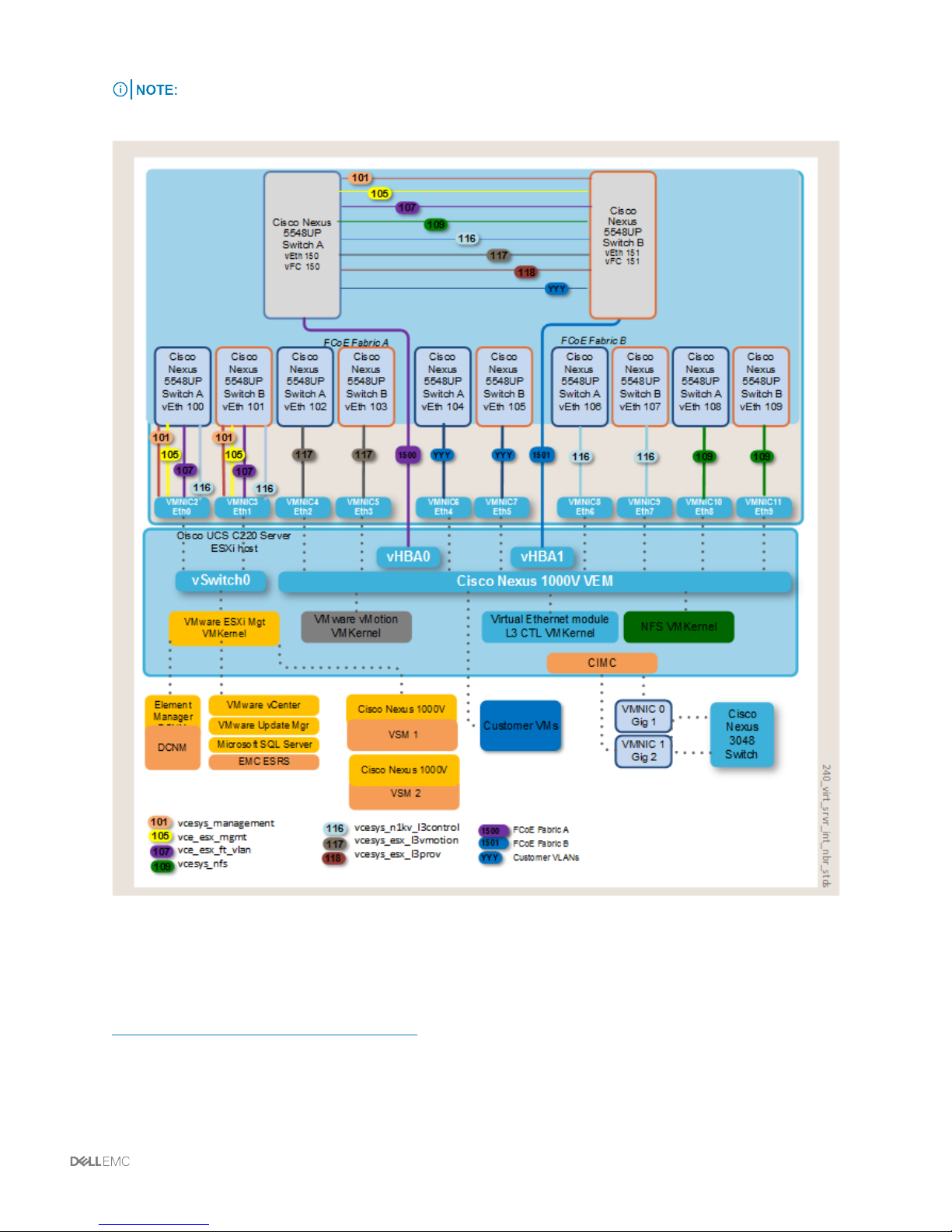
In the following illustration and in the following sections, the server is connected to port Eth1/7
on both Cisco Nexus 5548UP Switches. Your configuration may be different.
Related information
Virtual server interface numbering standards (see page 25)
Managing compute resources | 22
Page 23

Adding virtualized servers: configuring static vEthernet interfaces on
the Cisco Nexus 5548UP switches
About this task
In this example procedure, the server is connected to port Eth1/7 on both Cisco Nexus 5548UP switches.
Before you begin
Make sure the host has been zoned, masked, and allocated an appropriate sized boot LUN. This
example assumes all VLANs are trunked where necessary.
Procedure
1 To enable virtual network tag (VNTag) for the port that connects to the server, on Cisco Nexus
5548UP switches A and B, type the following commands in configuration mode:
interface Ethernet 1/7
switchport mode vntag
2 Create the VLANs (if needed):
vlan 301
name PROD-VLAN-301
3 Create the vEthernet port-profile. (This step is optional, most port-profiles should already be
created.)
port-profile type vethernet PROD-VLAN-301
switchport access vlan 301
switchport mode access
state enabled
23 | Managing compute resources
Page 24

4 Create static vEthernet interfaces (on both Cisco Nexus 5548UP switches) for the server’s vNICs.
5548-A
interface Vethernet700
inherit port-profile management
bind interface Ethernet1/7 channel 1
interface Vethernet702
inherit port-profile vmotion
bind interface Ethernet1/7 channel 5
interface Vethernet704
inherit port-profile production
bind interface Ethernet1/7 channel 7
interface Vethernet706
inherit port-profile n1k_L3_control
bind interface Ethernet1/7 channel 9
interface Vethernet708 (If unified configuration)
inherit port-profile nfs
bind interface Ethernet1/7 channel 11
5548-B
interface Vethernet701
inherit port-profile management
bind interface Ethernet1/7 channel 2
interface Vethernet703
inherit port-profile vmotion
bind interface Ethernet1/7 channel 6
interface Vethernet705
inherit port-profile production
bind interface Ethernet1/7 channel 8
interface Vethernet707
inherit port-profile n1k_L3_control
bind interface Ethernet1/7 channel 10
interface Vethernet709 If unified configuration)
inherit port-profile nfs
bind interface Ethernet1/7 channel 12
5 Create the vEthernet and virtual Fibre Channel (vFC) interfaces on Cisco Nexus 5548-A and add
the vFC interface to the virtual storage area network (VSAN) database. On Cisco Nexus 5548-A
only, enter the following commands:
interface Vethernet750
switchport mode trunk
switchport trunk allowed vlan 1,1500 (replace 1500 with Fabric A FCoE VLAN)
bind interface Ethernet1/7 channel 3
interface vfc750
bind interface Vethernet750
switchport trunk allowed vsan 10 (replace 10 with Fabric A VSAN)
no shutdown
vsan database
vsan 10 interface vfc 750 (replace 10 with Fabric A VSAN)
Managing compute resources | 24
Page 25

6 Create the vEthernet and vFC interfaces for booting on Cisco Nexus 5548-B and add the vFC to
the VSAN database. On Cisco Nexus 5548-B only, enter the following commands:
interface Vethernet751
switchport mode trunk
switchport trunk allowed vlan 1,1501 (replace 1501 with Fabric B FCoE VLAN)
bind interface Ethernet1/7 channel 4
interface vfc751
bind interface Vethernet751
switchport trunk allowed vsan 11 (replace 11 with Fabric B VSAN)
no shutdown
vsan database
vsan 11 interface vfc 751 (replace 11 with Fabric B VSAN)
Virtual server interface numbering standards
The following table provides the numbering standards for the virtual server interfaces. Servers are racked
from the bottom of the cabinet from A (1) to L (12).
Server Managemen
t vEth
Interface
5548-A5548-B5548-A5548-B5548-A5548-B5548-A5548-B5548-A5548-B5548-A5548-B5548-A5548-
A (1) 100 101 102 103 104 105 106 107 108 109 150 151 150 151
B (2) 200 201 202 203 204 205 206 207 208 209 250 251 250 251
C (3) 300 301 302 303 304 305 306 307 308 309 350 351 350 351
D (4) 400 401 402 403 404 405 406 407 408 409 450 451 450 451
E (5) 500 501 502 503 504 505 506 507 508 509 550 551 550 551
F (6) 600 601 602 603 604 605 606 607 608 609 650 651 650 651
G (7) 700 701 702 703 704 705 706 707 708 709 750 751 750 751
H (8) 800 801 802 803 804 805 806 807 808 809 850 851 850 851
I (9) 900 901 902 903 904 905 906 907 908 909 950 951 950 951
J (10) 1000 1001 1002 1003 1004 1005 1006 1007 1008 1009 1050 1051 1050 1051
K (11) 1100 1101 1102 1103 1104 1105 1106 1107 1108 1109 1150 1151 1150 1151
vMotion
vEth
Interface
VM Data
vEth
Interface
VEM L3
Control
vEth
Interface
NFS vEth
Interface
FCoE vEth
Interface
FCoE vFC
Interface
B
L (12) 1200 1201 1202 1203 1204 1205 1206 1207 1208 1209 1250 1251 1250 1251
Adding virtualized servers: modifying the Cisco UCS C220
Server components
Perform the tasks in the following sections to modify the Cisco UCS C220 Server.
25 | Managing compute resources
Page 26

Enabling network interface virtualization on the converged network
adapter
To enable VNTAG on the converged network adapter (CNA), perform the following steps:
Procedure
1 Log on to Cisco Integrated Management Controller (CIMC) on the server. On the left pane, select
Inventory. On the top right pane, select Cisco VIC Adapters. On the middle right pane, ensure
that General is selected. Select Modify Adapter Properties.
2 Select Enable VNTAG Mode and click Save Changes.
3 Reboot the server. On the left pane, select Summary > Power Cycle Server and select OK.
Configuring the management vNICs
To configure the management vNICs, perform the following steps:
Procedure
1 Log on to CIMC on the server. Select Inventory > Network Adapters > vNICS.
2 On the vNIC tab, select Eth0 and select Properties.
3 Verify that the Uplink Port field is set to 0.
4 Clear the PXE Boot check box. (It should not be selected.)
5 Set the Port Profile to management.
6 Verify that the Channel Number field is set to 1.
7 Click Save Changes.
8 Repeat these steps for Eth1, except make sure the Uplink Port field is set to 1 and the Channel
Number field is set to 2.
9 Click Save Changes.
Configuring the vSphere vMotion vNICs
To configure the vSphere vMotion vNICs, perform the following steps:
Procedure
1 Select Inventory > Network Adapters > vNICS .
2 Select Add.
3 In the Name field, enter Eth2.
4 Ensure the Uplink Port field is set to 0.
Managing compute resources | 26
Page 27

5 Select Trust Host CoS.
6 In the Channel Number field, enter 5.
7 In the Port Profile field, select vmotion.
8 Click Add vNIC.
9 Repeat these steps for Eth3, except ensure the Uplink Port field is set to 1, and in the Channel
Number field, enter 6.
Configuring the production vNICs
To configure the production vNICs, perform the following steps:
Procedure
1 Select Inventory > Network Adapters > vNICS.
2 Select Add.
3 In the Name field, enter Eth4.
4 Ensure the Uplink Port field is set to 0.
5 Select Trust Host CoS.
6 In the Channel Number field, enter 7.
7 In the Port Profile field, select production.
8 Click Add vNIC.
9 Repeat these steps for Eth5, except ensure the Uplink Port field is set to 1, and in the Channel
Number field, enter 8.
Configuring the Cisco Nexus 1000V Switch layer 3 Control vNICs
To configure the Cisco Nexus 1000V Switch layer 3 Control vNICs, perform the following steps:
Procedure
1 Select Inventory > Network Adapters > vNICS.
2 Select Add.
3 In the Name field, enter Eth6.
4 Ensure the Uplink Port field is set to 0.
5 Select Trust Host CoS.
6 In the Channel Number field, enter 9.
27 | Managing compute resources
Page 28

7 In the Port Profile field, select n1k_L3_control.
8 Click Add vNIC.
9 Repeat these steps for Eth7, except ensure the Uplink Port field is set to 1, and in the Channel
Number field, enter 10.
Configuring the NFS vNICs (Unified configuration only)
If you have a unified configuration, use the following steps to configure the NFS vNICs:
Procedure
1 Select Inventory > Network Adapters > vNICS.
2 Select Add.
3 In the Name field, enter Eth8.
4 In the MTU field, enter 9000.
5 Ensure the Uplink Port field is set to 0.
6 Select Trust Host CoS.
7 In the Channel Number field, enter 11.
8 In the Port Profile field, select nfs.
9 Click Add vNIC.
10 Repeat these steps for Eth9, except ensure the Uplink Port field is set to 1, and in the Channel
Number field, enter 12.
Configuring the virtual HBAs
To configure the virtual HBAs (vHBAs), perform the following steps:
Procedure
1 Select Inventory > Network Adapters > Adapter Cards.
2 From the vHBA tab, select FC0 and click Properties.
3 Select FC SAN Boot.
4 Verify that the Uplink Port field is set to 0.
5 Set the Default VLAN field to 1500.
6 Verify that the Channel Number field is set to 3.
7 Verify that the Port Profile field is blank.
Managing compute resources | 28
Page 29

8 Click Save Changes.
9 Repeat these steps for FC1, except make sure the Uplink Port field is set to 1, the Default
VLAN field is set to 1501, and the Channel Number field is set to 4.
Power cycling the host and verifying the host virtual Fibre Channel
After configuring all the components, perform the following steps:
Procedure
1 Power cycle the host.
2 Log on to both Cisco Nexus 5548UP Switches and ensure the host’s virtual Fibre Channel (vFC)
interface is up. For example, you can use the command show interface brief. Additional
vEthernet interfaces do not appear until the operating system is loaded.
Adding virtualized servers: modifying boot options
To configure the boot options, perform the tasks in the following sections.
Configuring the boot table
To configure the boot table, perform the following steps:
Procedure
1 Log on to CIMC on the server. On the left pane, select Inventory > Network > Adapters >
vHBAs.
2 Highlight fc0 and select Boot > Table.
3 Select Add and enter the first target for SAN booting and LUN ID. Select Add > Boot > Entry.
4 Select Add and enter the second target for SAN booting and LUN ID. Select Add Boot Entry.
5 Select Close.
6 Repeat these steps for fc1.
Mapping to the ISO file and rebooting the server
To map the ISO file, perform the following tasks:
Procedure
1 Log on to CIMC on the server. On the left pane, select Summary.
2 Select Launch KVM > Console.
3 On the Virtual > Media tab, select Add > Image.
29 | Managing compute resources
Page 30

4 Browse to the ISO file you will be installing and select Mapped.
5 Reboot the server.
Updating the boot order in BIOS
To update the boot order in BIOS, perform the following steps:
Procedure
1 During the boot process, when prompted in the BIOS, press F6 to enter the Boot menu.
2 Select Enter > Setup and press Enter.
3 Select Boot > Options.
4 Under UCSM boot order rules, press Enter, and change to Strict. Press Enter.
5 Under Boot Option #1, press Enter and select Cisco Virtual CD/DVD. Press Enter.
6 Under Boot Option #2, select DGC. Press Enter.
7 Under Hard Drive BBS Priorities, press Enter and select the following:
a For Boot Option #1, select the SP port to boot from first. Press Enter.
b For Boot Option #2, select the SP port to boot from second. Press Enter.
c For Boot Option #3, select the SP port to boot from third. Press Enter.
d For Boot Option #4, select the SP port to boot from fourth. Press Enter.
8 Press F10 to save and exit, select Yes to confirm. Press Enter.
9 Continue with normal operating system installation procedures.
Adding a bare metal host: overview
The Converged System can have half of the servers as bare metal servers. Dell EMC provides limited
support for bare metal servers. For more information, consult Support about the Bare Metal Support
Policy.
Adapter failover is recommended, which removes the need to configure NIC teaming in the operating
system.
With the Cisco NX-OS Adapter-FEX feature, there are two ways to logically configure the Cisco Nexus
5548UP Switches vEthernet interfaces for connectivity to the servers:
Create static vEthernet interfaces on the Cisco Nexus 5548UP Switches, which is the standard
•
for virtual servers. Cisco Nexus 5548UP Switches are configured similarly and conform to
standards, which aides with identification and troubleshooting. Valid interface IDs should be less
than 32768.
Managing compute resources | 30
Page 31

Create dynamic vEthernet interfaces of the Cisco Nexus 5548UP Switches, which entails less
•
logical configuration but sacrifices some customization. vEthernet interfaces are dynamically
created as the server boots up, with IDs greater than 32768. Once the vEthernet interfaces are
created and the configuration is saved, the interfaces remain the same across reboots.
For more information, see the Cisco white paper: Network Adapter Virtualization Design (Adapter-FEX)
with Cisco Nexus 5500 Switches and Cisco Nexus 2232 Fabric Extenders.
Related information
Bare metal host dynamically created interface numbering standards (see page 39)
Bare metal host static interface numbering standards (see page 35)
Statically configuring vEthernet interfaces
This topic explains how to statically configure dual vNIC (fail-over) vEthernet interfaces on the Cisco
Nexus 5548UP Switches.
About this task
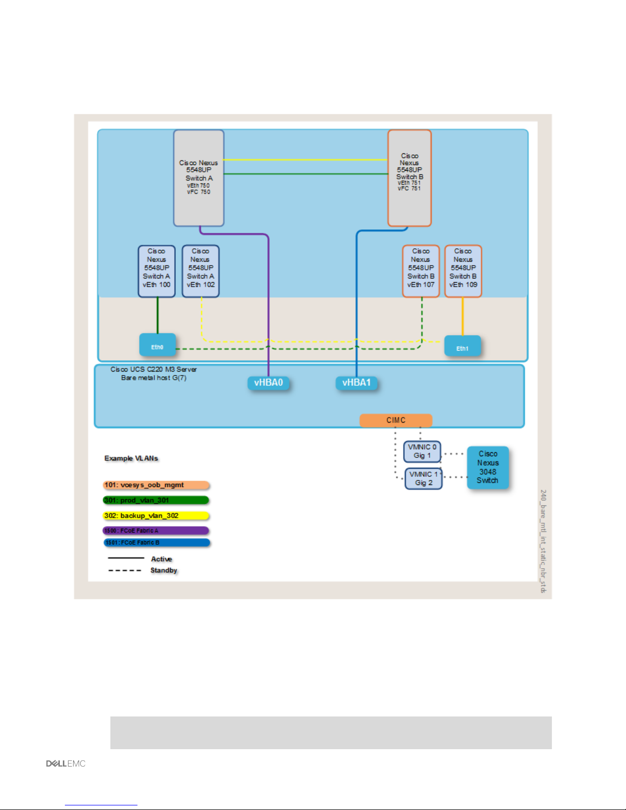
The server in this example (Server 7) is connected to port Eth1/7 on both Cisco Nexus 5548UP Switches,
as shown in the following illustration. Your configuration may be different.
31 | Managing compute resources
Page 32
Before you begin
Make sure the host has been zoned, masked, and allocated an appropriately sized boot LUN. This
example assumes all VLANs are trunked where necessary.
On Cisco Nexus 5548UP Switches A and B, enter the following commands:
Procedure
1 Enter the following commands in configuration mode to enable virtual network tagging (VNTag)
for the port that connects to the server:
interface Ethernet 1/7
switchport mode vntag
Managing compute resources | 32
Page 33

2 Create the VLANs:
vlan 301
name PROD-VLAN-301
vlan 302
name BACKUP-VLAN-302
3 Create the vEthernet port-profile:
port-profile type vethernet PROD-VLAN-301
switchport access vlan 301
switchport mode access
state enabled
port-profile type vethernet BACKUP-VLAN-302
switchport access vlan 302
switchport mode access
state enabled
4 Create static vEthernet interfaces (on both Cisco Nexus 5548UP Switches) for the server's
vNICs.
Due to failover mode and static vETH interface creation, identical vETH interfaces
must be created on both Cisco Nexus 5548UP Switches.
5548-A
interface Vethernet700
inherit port-profile PROD-VLAN-301
bind interface Ethernet1/7 channel 1
interface Vethernet701
inherit port-profile BACKUP-VLAN-302
bind interface Ethernet1/7 channel 2
5548-B
interface Vethernet700
inherit port-profile PROD-VLAN-301
bind interface Ethernet1/7 channel 1
interface Vethernet701
inherit port-profile BACKUP-VLAN-302
bind interface Ethernet1/7 channel 2
5 Create the vEthernet and vFC interfaces on Cisco Nexus 5548-A and add the VFC interface to
the virtual storage area network (vSAN) database. On the Cisco Nexus 5548-A Switch only, enter
the following commands:
interface Vethernet750
switchport mode trunk
switchport trunk allowed vlan 1,1500
bind interface Ethernet1/7 channel 3
interface vfc750
bind interface Vethernet750
switchport trunk allowed vsan 10
no shutdown
vsan database
vsan 10 interface vfc 750
33 | Managing compute resources
Page 34

6 Create the vEthernet and vFC interfaces for booting on the Cisco Nexus 5548-B Switch and add
the vFC to the vSAN database. On the Cisco Nexus 5548-B Switch only, enter the following
commands:
interface Vethernet751
switchport mode trunk
switchport trunk allowed vlan 1,1501
bind interface Ethernet1/7 channel 4
interface vfc751
bind interface Vethernet751
switchport trunk allowed vsan 11
no shutdown
vsan database
vsan 11 interface vfc 751
Some operating system installations require only one active path to storage. If this is
the case, one of the paths can be shut down on the Cisco Nexus 5548UP Switch. For
example, on 5548-B, you can enter the following commands:
interface vfc 751
shutdown
7 After successful installation of the operating system, you can enable the interface with the
following commands:
interface vfc 751
no shutdown
Related information
Bare metal host static interface numbering standards (see page 35)
Managing compute resources | 34
Page 35

Bare metal host static interface numbering standards
The following table provides the numbering standards for the bare metal interfaces. Servers are racked
from the bottom of the cabinet from A (1) to L (12).
Server Production
vEth Interface
5548-A 5548-B 5548-A 5548-B 5548-A 5548-B 5548-A 5548-B
A (1) 100 100 101 101 150 151 150 151
B (2) 200 200 201 201 250 251 250 251
C (3) 300 300 301 301 350 351 350 351
D (4) 400 400 401 401 450 451 450 451
E (5) 500 500 501 501 550 551 550 551
F (6) 600 600 601 601 650 651 650 651
G (7) 700 700 701 701 750 751 750 751
H (8) 800 800 801 801 850 851 850 851
I (9) 900 900 901 901 950 951 950 951
J (10) 1000 1000 1001 1001 1050 1051 1050 1051
K (11) 1100 1100 1101 1101 1150 1151 1150 1151
L (12) 1200 1200 1201 1201 1250 1251 1250 1251
Backup
vEth Interface
FCoE
vEth Interface
FCoE
vFC Interface
Related information
Bare metal host static interface numbering standards (see page 35)
Dynamically configuring vEthernet interfaces
This topic explains how to dynamically configure dual vNIC (fail-over) vEthernet interfaces on the Cisco
Nexus 5548UP Switches.
Before you begin
Make sure that the host has been zoned, masked, and allocated an appropriate sized boot LUN. This
example assumes all VLANs are trunked where necessary.
35 | Managing compute resources
Page 36
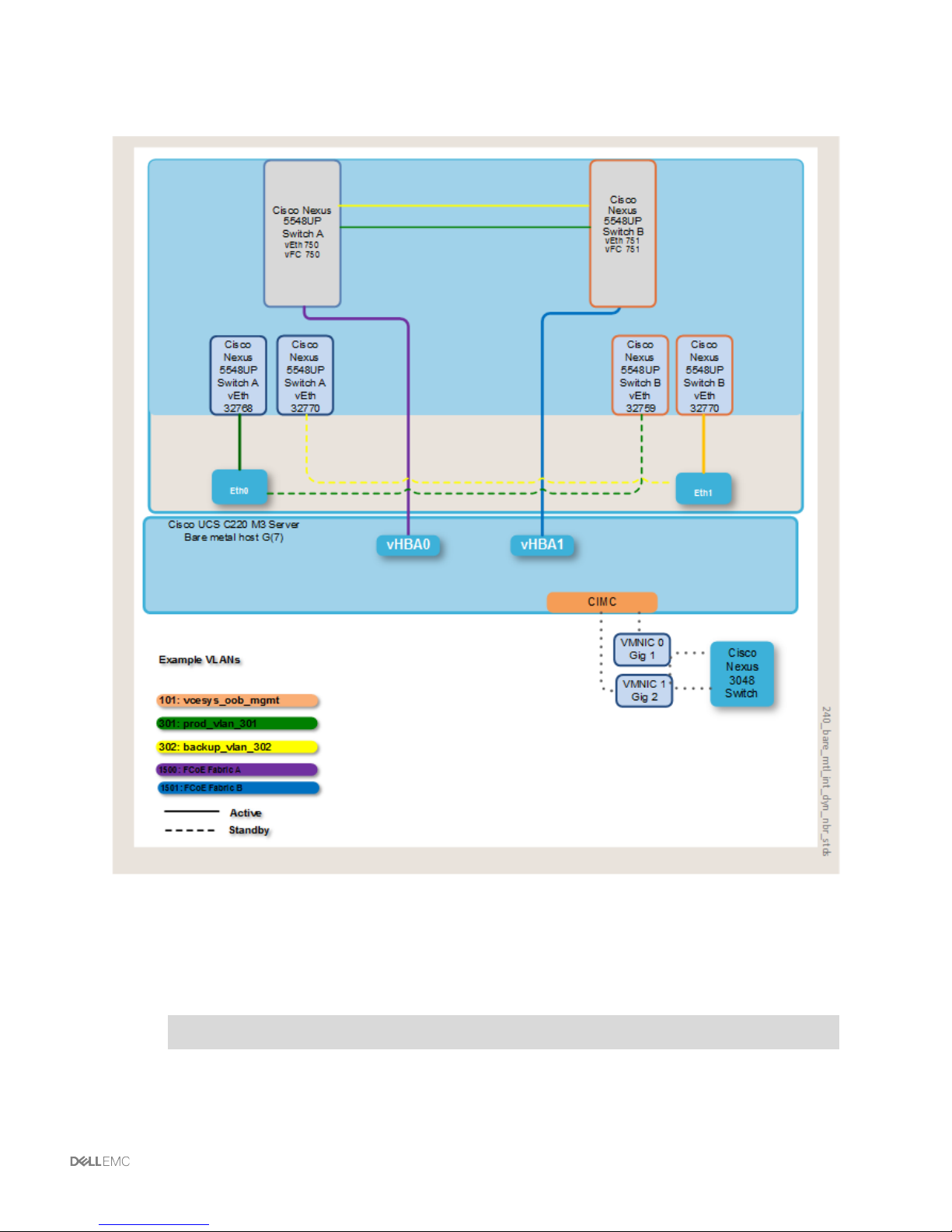
The server (Server 7) in this example is connected to port Eth1/7 on both Cisco Nexus 5548UP switches,
as shown in the following illustration. Your configuration may be different.
On Cisco Nexus 5548UP Switches A and B, enter the following commands:
Procedure
1 Enable the auto-creation of the Cisco Nexus 5548UP Switches vEthernet interfaces:
vethernet auto-create
Managing compute resources | 36
Page 37

2 Enable virtual network tagging (VNTag) for the port that connects to the server:
interface Ethernet 1/7
switchport mode vntag
3 Create the VLANs:
vlan 301
name PROD-VLAN-301
vlan 302
name BACKUP-VLAN-302
4 Create the vEthernet port-profile:
port-profile type vethernet PROD-VLAN-301
switchport access vlan 301
switchport mode access
state enabled
port-profile type vethernet BACKUP-VLAN-302
switchport access vlan 302
switchport mode access
state enabled
5 Create the vEthernet and vFC interfaces on the Cisco Nexus 5548-A Switch and add the VFC
interface to the vSAN database. On the Cisco Nexus 5548-A Switch only, enter the following
commands:
interface Vethernet750
switchport mode trunk
switchport trunk allowed vlan 1,1500
bind interface Ethernet1/7 channel 3
interface vfc750
bind interface Vethernet750
switchport trunk allowed vsan 10
no shutdown
vsan database
vsan 10 interface vfc 750
37 | Managing compute resources
Page 38

6 Create the vEthernet and vFC interfaces for booting on the Cisco Nexus 5548-B Switch and add
the vFC to the vSAN database. On the Cisco Nexus 5548-B Switch only, enter the following
commands:
interface Vethernet751
switchport mode trunk
switchport trunk allowed vlan 1,1501
bind interface Ethernet1/7 channel 4
interface vfc751
bind interface Vethernet751
switchport trunk allowed vsan 11
no shutdown
vsan database
vsan 11 interface vfc 751
Some operating system installations require only one active path to storage. If this is
the case, one of the paths can be shut down on the Cisco Nexus 5548UP Switch. For
example, on Cisco Nexus 5548-B, you can enter the following commands:
interface vfc 751
shutdown
7 After successful installation of the operating system, you can enable the interface with the
following commands:
interface vfc 751
no shutdown
Related information
Bare metal host dynamically created interface numbering standards (see page 39)
Bare metal host static interface numbering standards (see page 35)
Managing compute resources | 38
Page 39

Bare metal host dynamically created interface numbering standards
The numbers for production and backup vEthernet interfaces are established when the server boots up,
and are greater than 32,768. Servers are racked from the bottom of the cabinet from A (1) to L (12).
Server Production
vEth Interface
5548-A 5548-B 5548-A 5548-B 5548-A 5548-B 5548-A 5548-B
A (1) > 32768 > 32768 > 32768 > 32768 150 151 150 151
B (2) > 32768 > 32768 > 32768 > 32768 250 251 250 251
C (3) > 32768 > 32768 > 32768 > 32768 350 351 350 351
D (4) > 32768 > 32768 > 32768 > 32768 450 451 450 451
E (5) > 32768 > 32768 > 32768 > 32768 550 551 550 551
F (6) > 32768 > 32768 > 32768 > 32768 650 651 650 651
G (7) > 32769 > 32769 > 32770 > 32770 750 751 750 751
H (8) > 32768 > 32768 > 32768 > 32768 850 851 850 851
I (9) > 32768 > 32768 > 32768 > 32768 950 951 950 951
J (10) > 32768 > 32768 > 32768 > 32768 1050 1051 1050 1051
K (11) > 32768 > 32768 > 32768 > 32768 1150 1151 1150 1151
L (12) > 32768 > 32768 > 32768 > 32768 1250 1251 1250 1251
Backup
vEth Interface
FCoE
vEth Interface
FCoE
vFC Interface
Related information
Bare metal host static interface numbering standards (see page 35)
Modifying the Cisco UCS C220 rack server components
On the Cisco UCS C220 rack server, perform the following tasks.
Procedure
1 Enable network interface virtualization on the converged network adapter.
a Log on to CIMC on the server. On the left pane select Inventory. On the top right pane select
Network Adapters. On the middle right pane ensure General is selected. Select Modify
Adapter Properties.
b Select Enable NIV Mode and click Save Changes.
c Reboot the server. On the left pane, select Summary > Power Cycle Server and select OK.
2 Configure virtual network interfaces on the hosts.
a Log on to CIMC on the server. Select Inventory > Network Adapters > vNICS.
b From the vNIC tab, select Eth0 and select Properties.
39 | Managing compute resources
Page 40

c If jumbo frames are required, change the MTU to 9000. Otherwise leave the setting at 1500.
d Verify that the Uplink Port field is set to 0, which ensures that in the event of a failure, traffic
fails over automatically to 5548-B.
e Clear the PXE Boot check box. It should not be selected.
f Set the Port Profile to PROD-VLAN-301.
g Select the box for Enable Uplink Failover.
h Enter a value of 5 for Failback Timeout.
i From the vNIC tab, select Eth1 and select Properties.
j If jumbo frames are required, change MTU to 9000. Otherwise leave the setting at 1500.
If you need only one port, skip the following three steps. This will result in the
second vNIC being disabled.
k Verify that the Uplink Port field is set to 1, which ensures that in the event of a failure, traffic
fails over automatically to 5548-A.
l Clear the PXE Boot check box. It should not be selected.
m Set the Port Profile to BACKUP-VLAN-302.
n Select the box for Enable Uplink Failover.
o Enter a value of 5 for Failback Timeout.
p Click Save Changes.
3 Configure the virtual HBAs.
a Select Inventory > Network Adapters > Adapter Cards.
b From the vHBA tab, select FC0 and click Properties.
c Select FC SAN Boot.
d Set the Default VLAN field to 1500 for Fabric A
e Click Save Changes.
f Repeat these steps for FC1, except make sure the Default VLAN field is set to 1501 for
Fabric B.
4 Power cycle the host and verify the host vFC.
a Power cycle the host.
b Log on to both Cisco Nexus 5548UP Switches and ensure the host's vFC interface is up.
Additional vEthernet interfaces do not appear until the operating system is loaded.
Managing compute resources | 40
Page 41

Related information
Bare metal host static interface numbering standards (see page 35)
Modifying boot options
To configure the boot options, perform the following tasks.
Procedure
1 Configure the boot table.
a Log on to CIMC on the server. On the left pane, select Inventory > Network Adapters >
vHBAs
b Highlight fc0 and click Boot Table.
c Select Add and enter the first target for SAN booting and LUN ID. Select Add Boot Entry.
d Select Add and enter the second target for SAN booting and LUN ID. Add Boot Entry.
e Select Close.
f Repeat these steps for fc1.
2 Map to the ISO file and reboot the server.
a Log on to CIMC on the server. On the left pane, select Summary.
b Select Launch KVM Console.
c On the Virtual Media tab, select Add Image.
d Browse to the ISO file you will be installing and select the Mapped check box.
e Reboot the server.
3 Update the boot order in BIOS.
a During the boot process, when prompted in the BIOS, press F6 to enter the Boot menu.
b Select Enter Setup and press Enter.
c Select Boot Options.
d Under UCSM boot order rules, press Enter and change to Strict. Press Enter.
e Under Boot Option #1, press Enter and select Cisco Virtual CD/DVD. Press Enter.
f Under Boot Option #2, select DGC. Press Enter.
41 | Managing compute resources
Page 42

g Under Hard Drive BBS Priorities, press Enter and select the following:
i For Boot Option #1, select the SP port to boot from first. Press Enter.
ii For Boot Option #2, select the SP port to boot from second. Press Enter.
iii For Boot Option #3, select the SP port to boot from third. Press Enter.
iv For Boot Option #4, select the SP port to boot from fourth. Press Enter.
h Press F10 to save and exit, select Yes to confirm. Press Enter.
i Continue with normal operating system installation procedures.
Related information
Bare metal host static interface numbering standards (see page 35)
Using the Cisco Trusted Platform Module
The Cisco Trusted Platform Module (TPM) is a computer chip that securely stores artifacts such as
measurements, passwords, certificates, or encryption keys, which are used to authenticate the
Converged System. The Cisco TPM provides authentication and attestation services that enable safer
computing in all environments.
The Cisco TPM module is available by default in the Converged System as a component in some Cisco
UCS Blade Servers and Rack Servers and is shipped disabled.
Dell EMC supports Cisco TPM hardware but does not support the Cisco TPM functionality. Using Cisco
TPM features involves using a software stack from a vendor with significant domain experience in trusted
computing. Consult your software stack vendor for configuration and operational considerations relating
to the Cisco TPMs.
For more information, refer to www.cisco.com.
Managing compute resources | 42
Page 43

Managing networking resources
Creating VLANs and ports on the Cisco Nexus 5548UP
Switch
Use this procedure to create VLANs and ports on the Cisco Nexus 5548UP Switch.
About this task
VLANs on the Cisco Nexus 5548UP Switches allow network administrators to create logical broadcast
domains that can span multiple switches, regardless of their locations. They allow groups of users to be
logically grouped without being physically located in the same place. For more information on configuring
VLANs on Cisco Nexus 5548UP Switches, refer to the Cisco Nexus 5000 Series NX-OS Software
Configuration Guide
Before you begin
VTP mode is OFF. VTP BPDUs are dropped on all interfaces of a Cisco Nexus 5000 Series Switch, which
partitions VTP domains if other switches have VTP turned on.
About this task
The Cisco Nexus 5000 Series Switch supports VLAN numbers 1 to 4094 in compliance with the IEEE
802.1Q standard. These VLANs are organized into ranges. You use each range slightly differently. The
switch is physically limited in the number of VLANs it can support. The hardware also shares this
available range with its VSANs. For details of the number of supported VLANs and VSANs, see the
"Configuration Limits" section of the Cisco Nexus 5000 Series NX-OS Software Configuration Guide. The
following table details the VLAN ranges:
VLAN numbers Range Use
1 Normal Cisco default. You can use this VLAN, but you cannot modify or delete it.
2 to 1005 Normal You can create, use, modify, and delete these VLANs.
1006 to 4094 Extended You can create, name, and use these VLANs. You cannot change the
following parameters:
State is always active.
•
VLAN is always enabled. You cannot shut down these VLANs.
•
3968 to 4047 and
4094
All configured ports belong to the default VLAN (VLAN1) when you first bring up the switch. The default
VLAN uses only default values, and you cannot create, delete, or suspend activity in the default VLAN.
Internally
allocated
These 80 VLANs, plus VLAN 4094, are for internal use. You cannot
create, delete, or modify these VLANs. You can display these VLANs and
their associated use.
You create a VLAN by assigning a number to it; you can delete VLANs and move them from the active
state to the suspended state. If you try to create a VLAN with an existing VLAN ID, the switch goes into
the VLAN submode but does not create the same VLAN again.
Newly created VLANs remain unused until ports are assigned to the VLAN. All ports are assigned to
VLAN1 by default.
43 | Managing networking resources
Page 44

Depending on the range of the VLAN, you can configure the following parameters for VLANs (except the
default VLAN):
VLAN name
•
Shutdown or no shutdown
•
When you delete a VLAN, the ports associated with that VLAN are shut down and no traffic flows.
However, the system retains the VLAN-to-port mapping for that VLAN. When you reenable or recreate the
specified VLAN, the system automatically reinstates those ports to that VLAN.
To create a VLAN in global configuration mode, log on to the Cisco Nexus 5000 Switch and enter the
following commands:
switch> enable
switch# configure terminal
switch(config)# vlan {vlan-id | vlan-range}
If you enter a number that is assigned to an internally allocated VLAN, the system returns an error
message. However, if you enter a range of VLANs and one or more of the specified VLANs is outside the
range of internally allocated VLANs, the command takes effect on only those VLANs outside the range.
Removing a VLAN from the Cisco Nexus series switches
Remove a VLAN from the Cisco Nexus switches using Cisco NX-OS commands.
About this task
IPv4 addresses are supported on Vblock Systems and VxBlock Systems.
Before you begin
Verify that the Cisco Nexus switches are up and reachable through the console or the management
connection.
Verify connectivity information for the Cisco Nexus switches, such as:
Console information
•
Credentials for logging on
•
IPv4 address
•
Access method (SSH/TELNET)
•
VLAN names
•
Procedure
1 To view all VLANs, type: show vlan
2 To enter configuration mode, type: configure terminal
Managing networking resources | 44
Page 45

3 To enter VLAN configuration mode, type: vlan vlan_id
4 To delete the specified VLAN, type: no vlan vlan_id
Configuring zones for storage
Zoning enables you to set up access control between storage devices or user groups. If you have
administrator privileges in your fabric, you can create zones to increase network security and to prevent
data loss or corruption. Zoning is enforced by examining the source-destination ID field.
About this task
For more information on configuring zones for storage, see the "Configuring and Managing Zones"
section of the Cisco Nexus 5000 Series Switch CLI Software Configuration Guide
Cisco Nexus 5000 Series Switches automatically support the following basic zone features (no additional
configuration is required):
Zones are contained in a VSAN.
•
Hard zoning cannot be disabled.
•
Name server queries are soft-zoned.
•
Only active zone-sets are distributed.
•
Unzoned devices cannot access each other.
•
A zone or zone-set with the same name can exist in each VSAN.
•
Each VSAN has a full database and an active database.
•
Active zone-sets cannot be changed, without activating a full zone database.
•
Active zone-sets are preserved across switch reboots.
•
Changes to the full database must be saved.
•
Zone reactivation (a zone-set is active and you activate another zone set) does not disrupt
•
existing traffic.
If required, you can also configure the following zone features:
Propagate full zone-sets to all switches on a per VSAN basis.
•
Change the default policy for unzoned members.
•
Bring E ports out of isolation.
•
Use the following steps to create and activate a zone:
Procedure
switch# configuration terminal
1
45 | Managing networking resources
Page 46

switch(config)# zone name zone-name vsan vsan-id
2
switch(config-zone)# member type value
3
switch(config)# zoneset activate name zoneset-name vsan vsan-id
4
Configuring Cisco Nexus 5000 Series NX-OS Adapter-FEX
software
The Cisco NX-OS Adapter-FEX feature combines the advantages of the FEX link architecture with server
I/O virtualization to create multiple virtual interfaces over a single Ethernet interface. This allows you to
deploy a dual-port NIC on the server and to configure more than two virtual interfaces that the server
sees as a regular Ethernet interface. TTis approach allows you to reduce power and cooling needs and to
reduce the number of network ports.
About this task
Adapter-FEX can be thought of as a way to divide a single physical link into multiple virtual links or
channels. Each channel is identified by a unique channel number, and its scope is limited to the physical
link. The physical link connects a port on a server network adapter with an Ethernet port on the switch.
This allows the channel to connect a vNIC on the server with a vEthernet interface on the switch. Packets
on each channel are tagged with a VNTag that has a specific source virtual interface identifier (VIF). The
VIF allows the receiver to identify the channel that the source used to transmit the packet.
For more information about the Adapter-FEX feature, see the
FEX Software Configuration Guide.
Procedure
1 Enable the Adapter-FEX feature on each of the switches to which the server is connecting.
switch# configure terminal
a
switch(config)# install feature-set virtualization
b
switch(config)# feature-set virtualization
c
(Optional) switch(config)# vethernet auto-create
d
2 Configure the switch by creating a port profile to support Adapter-FEX.
switch# port-profile type vethernet port-profile_name
a
switch# switchport mode trunk
b
switch# switchport trunk allowed vlan 5,6,8-10
c
switch# state enabled
d
Cisco Nexus 5000 Series NX-OS Adapter-
switch# configure terminal
e
f switch(config)# interface Ethernet1/5
switch(config-if)# switchport mode vntag
g
Managing networking resources | 46
Page 47

3 Configure a server network adapter. Use the network adapter configuration utility on the server to
enable NIV mode on the network adapter. See the documentation of your specific server network
adapter for details. To complete the configuration, you might have to reboot the server to reset the
network adapter. For the Cisco UCS 1225 VIC, refer to the Cisco UCS 1225 VIC documentation.
When connecting the server network adapter to the enabled VNTag mode Ethernet port on a
switch or to a FEX, a handshake is initiated. An exchange of information about NIV capabilities
takes place and communications begin in VNTag mode. The switch passes the list of configured
port-profiles (type vEthernet) down to the adapter. These port-profile names are displayed in the
server network adapter’s configuration utility as options for selection.
Only port-profile names are passed to the server network adapter. The configurations in the portprofile are not passed to the server network adapter. If the server network adapter is not
connected to the switch, it is still possible to configure the vNICs on the server. However the portprofile names are not available on the adapter.
4 Configure vNICs on Server Network Adapter. Use the network adapter configuration utility on the
server to create the appropriate number of vNICs. Create each vNIC with the appropriate
properties, such as unique channel number, MAC address, uplink failover properties, or portprofile names. After the initial handshake and negotiation, the list of port-profiles configured on
the switch are available on the server adapter. You can associate these port-profile names to the
vNICs.
Each vNIC has a unique channel number associated with it. A vNIC is identified on the
switch by the bind command that associates a physical port and the vNIC’s channel
number to a vEthernet interface. Refer to the documentation of your specific server
network adapter for details. For the Cisco UCS 1225 VIC, refer to the Cisco UCS 1225
VIC documentation.
47 | Managing networking resources
Page 48

5 Initialize the Server Network Adapter. After you configure the vNICs on the server network
adapter, you might have to reboot the server and reset the server network adapter and reload the
drivers. See the documentation for your specific server network adapter for details. When the
configuration is complete, the server network adapter and the switch re-establishes a link and
performs the initial handshake and negotiation process. The server network adapter and the
switch also establish higher level control plane connectivity using the Virtual Interface
Configuration (VIC) protocol.
The VIC protocol allows you to provision and manage virtual interfaces on a remote
device.
When the VIC protocol connectivity is established, the server network adapter requests
that the switch create a vEthernet interface for each vNIC that is configured on the
server network adapter. The server network adapter also passes the following
attributes over the uplink in addition to the create vEthernet interface request:
—
Port-profile name
—
Channel number
—
Active/standby status
The switch responds by creating a vEthernet interface for each vNIC on the server network
adapter and associates the port-profile and channel number to the vEthernet interface. The
server boot process might be held at the BIOS configuration phase until the vEthernet creation
has completed. After the vEthernet is created, the boot process resumes and the operating
system is loaded. Refer to the documentation for your specific adapter for details.
The global configuration command, no vethernet auto-create, stops the vEthernet interfaces
from being automatically created. If the switch is not configured with the vethernet auto-create
command, you must configure the vEthernet interfaces manually with the appropriate binding and
port-profile configurations.
vEthernet interfaces created by the switch are numbered automatically as they are created.
These vEthernet numbers start from 32769. The switch picks the lowest unused number when
creating a vEthernet interface. When you manually create vEthernet interfaces, you may select
any number for the vEthernet . However, as a best practice, you should choose a number that is
less than 32678.
Manually creating virtual Ethernet interfaces
When a server network adapter is connected to a VNTag-mode Ethernet interface on a switch, the
vEthernet interfaces are created. However, vEthernet interfaces can also be created manually interface
vethernet veth-id command.
When manually configuring vEthernet interfaces, use the no vethernet auto-create command to disable
the automatic creation of vEthernet interfaces.
When a server network adapter is connected and a request to create a vEthernet is received,
the switch checks for a manually configured vEthernet interface that matches the channel
number of the vEthernet creation request. If the manually configured vEthernet interface
already exists, it is used and a new vEthernet interface is not created.
The commands in the following example manually create a vEthernet interface:
Managing networking resources | 48
Page 49

5548A:
interface Vethernet100 (defines the vethernet interface)
inherit port-profile management (defines the port-profile to apply)
bind interface Ethernet1/1 channel 1 (defines the physical port connected
to the server and the channel of the vNIC)
5548B:
interface Vethernet101 (defines the vethernet interface)
inherit port-profile management (defines the port-profile to apply)
bind interface Ethernet1/1 channel 2 (defines the physical port connected
to the server and the channel of the vNIC)
Managing virtual HBA interfaces on the Cisco UCS VIC 1225
The Cisco UCS VIC1225 is a high-performance, converged network adapter that provides acceleration
for the various new operational modes introduced by server virtualization. It brings superior flexibility,
performance, and bandwidth to the new generation of Cisco UCS C-Series Rack-Mount Servers.
The Cisco UCS VIC 1225 implements the Cisco Virtual Machine Fabric Extender (VM-FEX), which unifies
virtual and physical networking into a single infrastructure. It provides VM visibility from the physical
network and a consistent network operations model for physical and virtual servers. In virtualized
environments, this highly configurable and self-virtualized adapter provides integrated, modular LAN
interfaces on Cisco UCS C-Series Rack-Mount Servers.
Later versions of Cisco CIMC firmware refer to the NIV feature as VNTag.
For more information about Cisco UCS VIC 1225 vHBAs, see the Cisco UCS C-Series Servers Integrated
Management Controller CLI Configuration Guide, Release 1.4.
Creating virtual HBAs
The Cisco UCS VIC 1225 provides two vHBAs (fc0 and fc1). If NIV mode is enabled, you can create up to
16 additional vHBAs.
Before you begin
Log on with administrator privileges through SSH to CIMC IP to create a vHBA.
Procedure
1 Server# scope chassis
2 Server /chassis# scope adapter num
3 Server /chassis/adapter# create host-fc-if name
4 Server /chassis/adapter/host-fc-if#commit
49 | Managing networking resources
Page 50

Results
Reboot the server to create the vHBA. If configuration changes are required, configure the new vHBA.
For more information about Cisco UCS VIC 1225 vHBAs, see the Cisco UCS C-Series Servers Integrated
Management Controller CLI Configuration Guide, Release 1.4. .
Related information
Modifying virtual HBA properties (see page 50)
Viewing virtual HBA properties
Use the show host-fc-if [fc0 | fc1] [detail] command to display the properties of a single
vHBA, if specified, or all vHBAs.
The following example displays the properties of both vHBAs in summary mode:
Server /chassis # scope adapter 1
Server /chassis/adapter # show host-fc-if
Name World Wide Port Name FC SAN Boot Uplink Port
-------- ------------------------ ----------- ----------fc0 20:00:00:22:BD:D6:5C:35 Disabled 0
fc1 20:00:00:22:BD:D6:5C:36 Disabled 1
The following example displays the properties of a specified vHBA in detail:
Server /chassis # scope adapter 1
Server /chassis/adapter # show host-fc-if fc0 detail
Name fc0:
World Wide Node Name: 10:00:00:22:BD:D6:5C:35
World Wide Port Name: 20:00:00:22:BD:D6:5C:35
FC SAN Boot: Disabled
Persistent LUN Binding: Disabled
Uplink Port: 0
MAC Address: 00:22:BD:D6:5C:35
CoS: 3
VLAN: NONE
Rate Limiting: OFF
PCIe Device Order: ANY
EDTOV: 2000
RATOV: 10000
Maximum Data Field Size: 2112
Modifying virtual HBA properties
To modify vHBA properties, log on to the switch with administrator privileges. You can use the following
commands to modify the properties.
For more information about Cisco UCS VIC 1225 vHBAs, see the
Management Controller CLI Configuration Guide, Release 1.4.
Cisco UCS C-Series Servers Integrated
Managing networking resources | 50
Page 51

To enter the host FC interface command mode for the specified vHBA, enter the following commands
through SSH to CIMC IP address:
Server# scope chassis
Server /chassis # scope adapter index
Server /chassis/adapter # scope host-fc-if {fc0 | fc1 | name}
From FC interface command mode, you can enter the following commands:
Command Description
set wwnn wwnn Unique World Wide Node Name (WWNN) for the adapter in the form
hh:hh:hh:hh:hh:hh:hh:hh.
set wwpn wwpn Unique World Wide Port Name (WWPN) for the adapter in the form
hh:hh:hh:hh:hh:hh:hh:hh.
set boot {disable | enable} Enables or disables FC SAN boot. The default is disabled.
set persistent-lun-binding
{disable | enable}
set mac-addr mac-addr MAC address for the vHBA.
set vlan {none | vlan-id} Default VLAN for this vHBA. Valid VLAN numbers are 1 to 4094. The default is none.
set cos cos-value Class of service (CoS) value to be marked on received packets unless the vHBA is
set rate-limit {off | rate} Maximum data rate for the vHBA. The range is 1 to 10000 Mbps; the default is off.
set order {any | 0-99} Relative order of this device for PCIe bus device number assignment; the default is
set error-detect-timeout
msec
set resource-allocationtimeout msec
set max-field-size size Maximum size of the Fibre Channel frame payload (in bytes) that the vHBA supports.
Enables or disables persistent LUN binding. The default is disabled.
configured to trust host CoS. Valid CoS values are 0 to 6; the default is 0. Higher
values indicate more important traffic.
any.
Error detect timeout value
(EDTOV), which is the number of milliseconds to wait before the system assumes
that an error has occurred. The range is 1000 to 100000; the default is 2000
milliseconds.
Resource allocation timeout value (RATOV), the number of milliseconds to wait
before the system assumes that a resource cannot be properly allocated. The range
is 5000 to 100000; the default is 10000 milliseconds.
The range is 1 to 2112; the default is 2112 bytes.
To enter FC error recovery mode, enter the scope error-recovery command from FC interface command
mode. From FC error recovery mode, you can enter the following commands:
Command Description
set fcp-error-recovery
{disable | enable}
set link-down-timeout
msec
Enables or disables FCP Error Recovery. The default is disabled.
Link down timeout value, the number of milliseconds the uplink port should be offline
before it informs the system that the uplink port is down and fabric connectivity has
been lost. The range is 0 to 240000; the default is 30000 milliseconds.
51 | Managing networking resources
Page 52

Command Description
set port-down-io-retrycount count
set port-down-timeout
msec
Port down I/O retries value, the number of times an I/O request to a port is returned
because the port is busy before the system decides the port is unavailable. The range
is 0 to 255; the default is 8 retries.
Port down timeout value, the number of milliseconds a remote Fibre Channel port
should be offline before informing the SCSI upper layer that the port is unavailable. The
range is 0 to 240000; the default is 10000 milliseconds.
To enter the interrupt command mode, enter the scope interrupt command from FC interface command
mode. From interrupt command mode, you can specify the FC interrupt mode using the set interrupt-
mode {intx | msi | msix} command. The modes are as follows:
intx: Line-based interrupt (INTx)
•
msi: Message-Signaled Interrupt (MSI)
•
msix: Message Signaled Interrupts with the optional extension (MSI-X). This is the recommended
•
and default option.
To enter the FC port command mode, enter the scope port command from FC interface command mode.
From FC port command mode, you can enter the following commands:
Command Description
set outstanding-io-count
count
I/O throttle count, the number of I/O operations that can be pending in the vHBA at one
time. The range is 1 to 1024; the default is 512 operations.
set max-target-luns count Maximum LUNs per target, the maximum number of LUNs that the driver will discover.
This is usually an operating system platform limitation. The range is 1 to 1024; the
default is 256 LUNs.
To enter FC fabric login command mode, enter the scope port-f-logi command from FC interface
command mode. From FC fabric login command mode, you can enter the following commands:
Command Description
set flogi-retries {infinite |
count}
set flogi-timeout msec FLOGI timeout value, the number of milliseconds that the system waits before it tries to
Fabric login (FLOGI) retries value, the number of times that the system tries to log on to
the fabric after the first failure. Enter a number between 0 and 4294967295 or enter
infinite; the default is infinite retries.
log on again. The range is 1 to 255000; the default is 2000 milliseconds.
To enter FC port login command mode, enter the scope port-p-logi command from FC interface
command mode. From FC port login command mode, you can enter the following commands:
Command Description
set plogi-retries count Port login (PLOGI) retries value, the number of times that the system tries to log on to the
fabric after the first failure. The range is 0 and 255; the default is 8 retries.
set plogi-timeout msec PLOGI timeout value, the number of milliseconds that the system waits before it tries to log
on again. The range is 1 to 255000; the default is 2000 milliseconds.
Managing networking resources | 52
Page 53

Upgrading the Cisco Nexus 3048 Switch software
Use this procedure to upgrade both the NX-OS Kickstart and NX-OS System images on the Cisco Nexus
3048 Switch.
About this task
Upgrade recommendations:
Upgrading the two images together.
•
Ensuring the version numbers of the images are the same.
•
Backing up the original configuration.
•
Verifying that the configuration has been updated successfully and then creating a backup of the
•
new configuration.
Ensuring two switches are upgraded. Verify that the first switch has not experienced a platform
•
outage before upgrading the second switch.
Before you begin
Obtain:
Console (terminal) access
•
Management IP access
•
A Cisco account to download any images
•
An SCP, TFTP, FTP, or SFTP server
•
Access to the software code
•
Release notes from Cisco
•
Sufficient free space on bootflash on the switch
•
Procedure
1 Go to the Cisco Support website and download the NX-OS Kickstart and NX-OS System
Software for the Cisco Nexus 3xxx series switch.
2 Upload the two files to the switch using TFTP, SCP, FTP, or SFTP to bootflash.
3 To back up the switch running the configuration, type:
copy running-config startup-config
53 | Managing networking resources
Page 54

4 To verify the switch has enough space for the new image, type:
switch# dir bootflash:
The system lists the contents of the bootflash:
495 Apr 06 03:47:56 2011 license_XXXXXXXX.lic
49152 Apr 06 03:51:08 2011 lost+found/
1893 May 26 23:14:43 2011 mts.log
25164288 Apr 06 03:41:50 2011 n3000-uk9-kickstart.5.0.2.N2.1.bin
156932426 Apr 06 03:42:36 2011 n3000-uk9.5.0.2.N2.1.bin
4096 Jan 01 03:45:25 2009 vdc_2/
4096 Jan 01 03:45:25 2009 vdc_3/
4096 Jan 01 03:45:26 2009 vdc_4/
Usage for bootflash://sup-local
299823104 bytes used
1351081984 bytes free
1650905088 bytes total
5 If there is not enough space, type:
delete bootflash:filename
If you delete the active system or kickstart image, do not reboot the switch.
6 To copy the updated images to the switch, type:
copy ftp: bootflash:
a When prompted for the source filename, type the filename of the kickstart bin file from the
Cisco download site. For example, n3000-uk9-kickstart.5.0.3.N1.1c.bin
b When prompted for the VRF, type management.
c Enter the hostname or IP address of the FTP server.
d Enter the username and password of the FTP server.
The system copies the images to the switch, and following message appears:
***** Transfer of file Completed Successfully *****
Managing networking resources | 54
Page 55

7 To display the impact of the upgrade, type:
switch(config)# show install all impact kickstart bootflash:n5000-uk9kickstart.5.0.3.N1.1c.bin
As the system performs the upgrade, it displays status messages like the following:
Verifying image bootflash:/n5000-uk9-kickstart.5.0.3.N1.1c.bin for boot variable
"kickstart".[####################] 100% -- SUCCESS
Verifying image bootflash:/n5000-uk9.5.0.2.N2.1.bin for boot variable "system".
[####################] 100% -- SUCCESS
Verifying image type.
Extracting "system" version from image bootflash:/n5000-uk9.5.0.2.N2.1.bin.
[####################] 100% -- SUCCESS
Extracting "kickstart" version from image bootflash:/n5000-uk9-kickstart.
5.0.3.N1.1c.bin.
[####################] 100% -- SUCCESS
Extracting "bios" version from image bootflash:/n5000-uk9.5.0.2.N2.1.bin.
[####################] 100% -- SUCCESS
Performing module support checks.
[####################] 100% -- SUCCESS
Notifying services about system upgrade.
[####################] 100% -- SUCCESS
Compatibility check is done:
Module bootable Impact Install-type Reason
------ -------- -------------- ------------ -----1 no n/a n/a Incompatible image
Images will be upgraded according to following table:
Module Image Running-Version New-Version Upg-Required
------ ---------- ---------------------- ---------------------- -----------1 system 5.0(2)N2(1) 5.0(2)N2(1) no
1 kickstart 5.0(2)N2(1) 5.0(3)N1(1c) no
1 bios v1.8.0(10/06/2010) v1.8.0(10/06/2010) no
1 power-seq v3.0 v3.0 no
2 power-seq v1.0 v1.0 no
1 uC v1.1.0.1 v1.0.0.14 no
Additional info for this installation:
-------------------------------------Port: port-channel52 in VLAN0001 is Designated. Topology change could occur during
ISSU.
Upgrade needs to be disruptive!!!
55 | Managing networking resources
Page 56

8 To install the new Cisco NX-OS images, type install all kickstart bootflash:n5000-
uk9-kickstart.5.0.3.N1.1c.bin system bootflash:n5000uk9.5.0.3.N1.1c.bin
To view the progress of the installation during the installation process, type show install
all. As the system performs the installation, it displays status messages like the following:
Verifying image bootflash:/n5000-uk9-kickstart.5.0.3.N1.1c.bin for boot variable
"kickstart". [####################] 100% -- SUCCESS
Verifying image bootflash:/n5000-uk9.5.0.3.N1.1c.bin for boot variable "system".
[####################] 100% -- SUCCESS
Verifying image type. [####################] 100% -- SUCCESS
Extracting "system" version from image bootflash:/n3000-uk9.5.0.3.N1.1c.bin.
[####################]
100% -- SUCCESS
Extracting "kickstart" version from image bootflash:/n3000-uk9-kickstart.5.0.3.N
1.1c.bin.
[####################] 100% -- SUCCESS
Extracting "bios" version from image bootflash:/n3000-uk9.5.0.3.N1.1c.bin.
[####################] 100% -- SUCCESS
Performing module support checks.
[####################] 100% -- SUCCESS
Notifying services about system upgrade.
[####################] 100% -- SUCCESS
Compatibility check is done:
Module bootable Impact Install-type Reason
------ -------- -------------- ------------ -----1 yes disruptive reset STP ISSU preupgrade check failed
- Upgrade needs to be disruptive!
Images will be upgraded according to following table:
Module Image Running-Version New-Version Upg-Required
------ ---------- ---------------------- ---------------------- -----------1 system 5.0(2)N2(1) 5.0(3)N1(1c) yes
1 kickstart 5.0(2)N2(1) 5.0(3)N1(1c) yes
1 bios v1.8.0(10/06/2010) v3.5.0(02/03/2011) yes
1 power-seq v3.0 v3.0 no
2 power-seq v1.0 v1.0 no
1 uC v1.1.0.1 v1.0.0.14 no
Additional info for this installation:
-------------------------------------Port: port-channel52 in VLAN0001 is Designated. Topology change could occur during
ISSU.
Upgrade needs to be disruptive!!!
If you are performing a disruptive upgrade, the following warning appears:
Switch will be reloaded for disruptive upgrade.
Do you want to continue with the installation (y/n)? [n] y
Install is in progress, please wait.
Performing runtime checks.
[####################] 100% -- SUCCESS
Setting boot variables.
[####################] 100% -- SUCCESS
Performing configuration copy.
[####################] 100% -- SUCCESS
Module 1: Refreshing compact flash and upgrading bios/loader/bootrom/power-seq.
Warning: please do not remove or power off the module at this time.
Note: Power-seq upgrade needs a power-cycle to take into effect.
On success of power-seq upgrade, SWITCH OFF THE POWER to the system and then, power
it up.
Note: Micro-controller upgrade needs a power-cycle to take into effect.
On success of micro-controller upgrade, SWITCH OFF THE POWER to the system and then,
power it up.
[####################] 100% -- SUCCESS
Finishing the upgrade, switch will reboot in 10 seconds.
Managing networking resources | 56
Page 57

2011 Sep 8 18:16:43 VSJ3X2N3048A Sep 8 18:16:43 %KERN-0SYSTEM_MSG: Shutdown Ports.. - kernel
2011 Sep 8 18:16:43 VSJ3X2N3048A Sep 8 18:16:43 %KERN-0-SYSTEM_MSG: writing reset
reason 49, - kernel
Broadcast message from root (Thu Sep 8 18:16:43 2011):
The system is going down for reboot NOW!
Type Y to continue with the installation.
9 When the switch reboots, to verify that the updated version of the software is running,type:
At the bottom of the output, the Last Reset section displays the previous running
version before the reboot.
show version.
The following information appears:
Cisco Nexus Operating System (NX-OS) Software
TAC support: http://www.cisco.com/tac
Copyright (c) 2002-2011, Cisco Systems, Inc. All rights reserved.
The copyrights to certain works contained herein are owned by
other third parties and are used and distributed under license.
Some parts of this software are covered under the GNU Public
License. A copy of the license is available at http://www.gnu.org/licenses/gpl.html.
Software
BIOS: version 3.5.0
loader: version N/A
kickstart: version 5.0(3)N1(1c)
system: version 5.0(3)N1(1c)
power-seq: Module 1: version v3.0
Module 2: version v1.0
Module 3: version v2.0
uC: version v1.1.0.1
BIOS compile time: 02/03/2011
kickstart image file is: bootflash:/n3000-uk9-kickstart.5.0.3.N1.1c.bin
kickstart compile time: 5/4/2011 3:00:00 [05/04/2011 10:43:31]
system image file is: bootflash:/n3000-uk9.5.0.3.N1.1c.bin
system compile time: 5/4/2011 3:00:00 [05/04/2011 12:35:20]
Hardware
cisco Nexus3048 Chassis ("O2 32X10GE/Modular Supervisor")
Intel(R) Xeon(R) CPU with 8299528 kB of memory.
Processor Board ID JAF1513CCCF
Device name: VSJ3X2N3048A
bootflash: 2007040 kB
Kernel uptime is 0 day(s), 0 hour(s), 8 minute(s), 43 second(s)
Last reset at 696441 usecs after Thu Sep 8 18:16:43 2011
Reason: Disruptive upgrade
System version: 5.0(2)N2(1)
Service:
plugin
Core Plugin, Ethernet Plugin
Downgrading Cisco Nexus switch software
Downgrade Cisco Nexus switch software to restore the original version after a failed upgrade.
Procedure
To reverse a Cisco Nexus series switch software upgrade, perform the upgrade steps using the earlier
version of the software.
57 | Managing networking resources
Page 58

Related information
http://www.cisco.com/c/en/us/td/docs/switches/datacenter/nexus3000/sw/upgrade/7_x/
Cisco_n3k_Upgrade_Downgrade_7x.html?
Cisco Nexus 9000 Series NX-OS Software Upgrade and Downgrade Guide
Managing networking resources | 58
Page 59

Managing storage resources
Logging on to a storage array
Use this procedure to log on to the storage array.
Before you begin
Before performing this task, obtain the:
IP addresses of the two storage processors.
•
IP address of the primary control station (unified only).
•
Username and password for the storage array.
•
Procedure
1 Open a browser and type the IP address of either storage processor or the primary control
station.
Always use the IP address of the primary control station when the Converged System
contains unified VNX.
2 From the EMC Unisphere window, click Start a new EMC Unisphere session.
3 Type your name and password for the storage array, or type the LDAP user ID (select Use LDAP
in this instance) and click Login.
4 From the NAT Mode window, type the required IP addresses, and click Add IP.
The NAT Mode window does not appear when connecting from within the Converged
System or when using the native IP addresses of the storage processors or the control
station. The NAT Mode window only appears when connecting to Unisphere from
outside of a Converged System.
5 When the Agreement window appears, click Accept.
6 From the EMC > Unisphere window, under the list of storage arrays, select a storage array.
7 From the main menu of the storage array, the remaining tasks that require action appear. The
menu bar at the top lists all of the options available for the array. Click any of the main menu
options to view the available sub-menus.
Creating storage pools
Use this procedure to create a storage pool in the storage array.
Before you begin
Verify that drives are available in the storage array in the storage pool.
59 | Managing storage resources
Page 60

About this task
Use the following guidelines:
Use drives in multiples of RAID group sizes. Create new virtual provisioning (VP) pools only to
•
support new application requirements.
Bare metal hosts require separate disk drives. The boot LUNs and data LUNs for bare metal
•
cannot coexist with the same disk groups or VP pools used for ESX boot and ESX data volumes.
RecoverPoint Replica Journals and Replica Volumes must be placed in a dedicated disk group
•
and VP pool. For example, for RAID 1/0 or RAID 6, add drives in multiples of 8. For RAID 5, add
drives in multiples of 5.
Bare metal applications require a dedicated storage pool.
•
Thin pools may reach an oversubscription ratio of 4:1. When a pool reaches 60 percent of
•
capacity, a warning event is generated. When a pool reaches 80 percent, more drives must be
added to bring the pool below 60 percent.
Procedure
1 Log on to the storage device on which you want to create the storage pool.
2 Select Storage > Storage Configuration > Storage Pools.
3 When the Storage Pools window appears, click Create.
4 From the Create Storage Pool window, select Pool for the Storage Pool Type, type the name of
the pool, and select a RAID type.
5 Under Disks, click Manual for disk selection and click Select.
6 From the Disk Selection window, a list of available disks appears. Highlight the disks you want to
use for the storage pool and use the arrow key to add them to the list of Selected Disks. Click
OK. When the Create Storage Pools window appears, the list of added disks appears.
7 Select Scheduled Auto-Tiering to enable FAST VP automated data movement if desired.
8 Select the Advanced tab to change the pool threshold from 70% to 60%.
9 Verify that all of the information is correct and click Apply.
10 When the confirmation window appears, click Yes.
11 A confirmation message appears or, if you selected a number of drives that is not a multiple of the
RAID group size, a warning appears. Click OK to confirm the success or No to go back and
reselect disks.
12 From the Pools menu, the last entry is the pool that has just been created and is in the process
of being initialized. Once complete, the State appears as Ready.
13 To verify the procedure, select Storage > Storage Configuration > Storage Pools. From the list
of storage pools, verify that the new pool appears.
Managing storage resources | 60
Page 61

What to do next
After the storage pool has been created, you can create LUNs in the storage pool.
Expanding a storage pool
Use this procedure to grow a storage pool.
Before you begin
Before performing this task, verify that storage pools exist and disk drives are available to expand the
storage pool. The best practice is for the pool to be expanded by the same number of drives in the pool,
but this is not always feasible.
About this task
Verify that UIM/P discovery occurs after expansion of the pool; otherwise, space is not seen as available
for provisioning.
Expand the storage group in multiples of the RAID group size.
A storage pool cannot be reduced to its previous size.
Procedure
1 Log on to the storage device to create the storage pool.
2 Select Storage > Storage Configuration > Storage Pools .
3 When the Pools window appears, select the storage pool and click Expand.
4 From the Expand Storage Pool window, under Disks, select Manual and click Select.
5 When the Disk Selection window appears, verify that All Cabinets is selected.
6 Under Available Disks, highlight a disk and use the arrow key to add it to the Selected Disks
field. Click OK.
7 From the Expanded Storage Pool window, view your pool, and click OK.
8 If your selection does not support best practices, an error message appears. You can click Yes to
continue or No to cancel out and repeat the procedure.
9 When the confirmation window appears, click OK.
10 To verify that disks have been added, right-click the storage pool and select Properties. Select
the Disks tab and view the storage pool. The list of disks should include the old disks and the
new ones that were added.
What to do next
Use the expanded capacity to grow existing LUNs or create new ones.
61 | Managing storage resources
Page 62

Monitoring a storage pool
Use this procedure to monitor pools in a storage array.
Procedure
1 Log on to Unisphere and select the storage array you want to monitor.
2 Select Storage > Storage Configuration > Storage Pools.
3 When the Pools window appears, select the storage pool you want to monitor and click
Properties.
4 From the Storage Pool Properties window, there are four tabs that can be used to monitor
different aspects of the storage pool. The General tab shows the physical and virtual capacities,
including total capacity, consumed capacity and the percentage full.
5 Select the Disks tab to view the state of the individual drives that make up the storage pool.
6 Click OK when done.
Creating a boot LUN
Use this procedure to create a boot LUN.
About this task
The information in this procedure is specific to environments or situations where Ionix UIM/P is not used.
To provision a new service using Ionix UIM/P, refer to the Ionix Unified Infrastructure Manager
Provisioning Center Administration and User Guide
As you create the LUNs, consider the following points:
Boot LUNs are created as thick LUNs.
•
VMware ESXi Boot LUNs are 10 GB.
•
Bare metal boot LUNs vary in size.
•
When creating a boot LUN, ensure that LUNs are distributed evenly across the SPs. Even LUN
•
IDs are owned by SP A, and odd LUN IDs are owned by SP B.
The sum capacity of all thin LUNs and LUNs (not the thin pools) and all RAID groups should not
•
exceed the maximum capacity of the array.
You can change a VP pool LUN allocation owner only by deleting the LUN. Make sure you
•
properly assign SP ownership and distribute the LUNs evenly across the SPs before adding data
to the LUNs.
Managing storage resources | 62
Page 63

Procedure
1 Log on to Unisphere and select a storage array to create the LUN.
2 Select Storage > LUNs > LUNs.
3 The LUNs menu shows a list of existing LUNs. To create a new LUN, click Create.
4 When the Create LUN window appears, under the General tab, select Pool for the Storage >
Pool > Type and the RAID type. Once the RAID type has been selected, the storage pools of
that RAID type appear.
5 Select the storage pool to create the LUN.
6 Under LUN > Properties > User > Capacity, enter the size of the LUN.
7 Select the next available LUN ID between 0 and 132 from the list of available IDs, and select 1 for
the number of LUNs to be created.
8 Under LUN > Name, select Name and enter a name for the LUN.
9 Select the Advanced tab to select the appropriate SP owner and click Apply.
10 When the confirmation message appear, click Yes and OK.
11 To create additional LUNs, repeat this procedure, or if you are finished, click Cancel to exit.
12 To verify that the LUN has been created, from the LUNs menu, look for the new LUN in the list.
Related information
Adding a host to a storage group (see page 66)
Creating a data LUN
Use this procedure to create a LUN in a storage pool.
Before you begin
Verify that there is available space on the storage pool for the LUN.
About this task
Create a LUN that is large enough to grow over time, but is not so large that other LUNs cannot be
created.
If Ionix UIM/P manages the Converged System resources, follow the Ionix Unified Infrastructure Manager
Provisioning Center Administration and User Guide to add storage to a host. The information in this
procedure is specific to environments or situations where Ionix UIM/P is not used.
As you create a data LUN, consider the following points:
VMware ESXi 5.x can support larger LUNs. Dell EMC recommends using a maximum size of 2
•
TB until larger LUNs have been validated.
63 | Managing storage resources
Page 64

Bare metal LUN sizes vary, depending on the application requirements.
•
When creating a LUN, ensure that LUNs are distributed evenly across the SPs. Even LUN IDs
•
are owned by SP A, and odd LUN IDs are owned by SP B.
You can change a VP pool LUN allocation owner only by deleting the LUN. Make sure you
•
properly assign SP ownership and distribute the LUNs evenly across the SPs before adding data
to the LUNs.
When using thin LUNs for VMware, ensure that the VMware Datastore is not created as thin.
•
The sum capacity of all thin and thick LUNs (not the thin pools) and all RAID groups should not
•
exceed the maximum capacity of the array.
Procedure
1 Log on to Unisphere and select a storage array to create the LUN.
2 Select Storage > LUNs > LUNs.
3 The LUNs menu shows a list of existing LUNs. To create a new LUN, click Create.
4 When the Create > LUN window appears, under the General tab, select Pool for the Storage
Pool Type and the RAID type. Once the RAID type has been selected, the storage pools of that
RAID type appear.
5 Select the storage pool to create the LUN.
6 Under LUN > Properties, check Thin, and under User > Capacity, type the size of the LUN.
7 Select a LUN ID from the list of available IDs, and select 1 for the number of LUNs to be created.
8 Under LUN > Name, select Name and type a name for the LUN.
9 Select the Advanced tab to select the appropriate SP owner and click Apply.
10 When the confirmation message appears, click Yes and OK.
11 To create additional LUNs, repeat this procedure, or if you are finished, click Cancel to exit.
12 To verify the LUNs were added, from the LUNs menu, look for the new LUN in the list.
Related information
Adding a LUN to a storage group (see page 66)
Expanding LUN capacity
Use this procedure to increase the capacity of a SAN Boot LUN or Data LUNs.
About this task
Use the VNX Unisphere GUI to expand already provisioned LUN.
Managing storage resources | 64
Page 65

Before you begin
Obtain the IP address and the log on credentials for the VNXe array.
•
Confirm that increasing LUN capacity will not exceed the total array capacity.
•
Procedure
1 Log on to Unisphere.
2 Select Storage > LUNs.
3 Right click the LUN that needs to be expanded and select Expand.
4 In the LUN Expand Storage dialog, specify the new user capacity.
5 Click OK.
6 Verify the LUN reflects the new expanded capacity.
Deleting a LUN
Deleting a LUN deletes all of the data associated with that LUN.
Procedure
1 Select Storage > LUNs > LUNs
2 From the list of existing LUNs, select the LUN and click Delete.
Creating a storage group
Use this procedure to create a storage group on a storage array using Unisphere.
Procedure
1 Log on to Unisphere and select a storage array to create the storage group.
2 Select Hosts > Storage Groups.
3 From the Storage Groups window, a list of existing storage groups in the storage array appears.
To create a new group, click Create.
4 When the Create Storage Group window appears, type a name and click Apply.
5 When the confirmation window appears, click Yes.
6 When the second confirmation window appears, you are prompted to add more LUNs. Click No
to end the procedure or click Yes to add more LUNs. Refer to the appropriate procedure for
adding LUNs and hosts.
7 To verify that the storage group was created, select Storage > Storage Groups and look for the
new storage group in the list.
65 | Managing storage resources
Page 66

8 To delete a storage group, select Hosts > Storage Groups. From the list of storage groups,
select the storage group and click Delete.
What to do next
Connect the hosts and the LUNs to the storage group.
Adding a host to a storage group
Use this procedure to connect hosts to a storage group.
Before you begin
Before performing this task, the storage group must exist, and the hosts that you want to connect to
should appear in the list of hosts seen by the storage array.
Procedure
1 Log on to Unisphere and select the storage array on which you want to connect the host.
2 Select Hosts > Storage Groups.
3 When the Storage Groups window appears, select a storage group to which you want to connect
the host and click Connect Hosts.
4 From the Storage Group Properties window, select the Hosts tab.
By default, Show Hosts: Not connected is selected. Do not change this setting
unless you want to add a host to more than one storage group.
5 From the list of available hosts, use the arrow key to select the host you want to add to the Hosts
to be Connected field, and click Apply.
6 When the confirmation messages appear, click Yes and OK.
7 To verify that the hosts were added, from the Storage Groups menu, right-click Storage Group,
and select Properties. Select the Hosts tab and look for the hosts you connected to the storage
group.
Related information
Adding a LUN to a storage group (see page 66)
Adding a LUN to a storage group
Use this procedure to connect a LUN to a storage group.
Before you begin
Verify that the LUNs and storage groups exist.
Managing storage resources | 66
Page 67

Procedure
1 Log on to Unisphere and select the storage array on which you want to connect the LUN.
2 Select Hosts > Storage Groups.
3 From the Storage Groups window, select a storage group and click Connect LUNs.
4 When the Storage Group Properties window appears, select the LUNs tab.
5 In the Show LUNs field, select ALL.
6 Under Available LUNs, expand the list, select the LUN you want to connect, and click Add.
7 When the LUN appears in the Selected LUNs field, modify the host ID, if necessary, and click
Apply.
Use the LUN ID as the host ID, except in the case of boot LUNs.
8 When the confirmation windows appear, click Yes and OK.
9 To view the LUNs, select Hosts > Storage Groups. Select the storage group and select
Properties. Select the LUNs tab and view the LUN.
Monitoring a RAID group
Monitor a RAID group on a storage array using Unisphere.
Procedure
1 Log on to Unisphere and select the storage array to monitor.
2 Select Storage > Storage Configuration > Storage Pools.
3 When the next screen appears, select the RAID Group tab.
4 Right-click the RAID group to monitor and select Properties.
5 From the RAID Group Properties window, the General, Disks, and Partitions tabs can be used
to monitor different aspects of the RAID group, such as total capacity and free capacity.
Using VMware EVC with Cisco UCS rack servers
Use these guidelines to ensure compatibility when upgrading Cisco UCS rack servers in a Converged
System.
Guidelines
Mixing Cisco UCS rack server types within a cluster is not recommended. However, there are instances
when it is necessary to mix rack types for certain situations, including upgrades.
67 | Managing storage resources
Page 68

When upgrading Cisco UCS rack servers in a Converged System, consider the following guidelines:
Enable EVC mode only if you are adding or planning to add hosts with newer CPUs to an existing
•
cluster.
Cisco UCS rack servers all support EVC mode Intel® Nehalem Generation (Xeon® Core™ i7).
•
Individual Cisco UCS rack servers support several EVC modes, but only Xeon Core i7 is a
commonly supported mode across all Cisco UCS rack servers. If the CPU feature sets are
greater than the EVC mode you are enabling, you may need to power down all VMs in the cluster
and enable or modify the EVC mode.
Some Cisco UCS rack servers support additional CPU features (such as those provided in 32-
•
nanometer EVC mode), but some of those features might not be enabled in the BIOS (due to
U.S. export rules). To ensure complete and reliable vMotion compatibility when mixing rack types
in a single cluster, use Intel Xeon® Core™ i7 EVC mode.
If all the Cisco UCS rack servers in the cluster have the same CPU type, set the EVC mode to
•
that of the CPU architecture. This allows vMotion compatibility between Cisco UCS rack servers
and other hosts.
Set the EVC mode before you add Cisco UCS rack servers with newer CPUs to the cluster. This
•
eliminates the need to power down the VMs running on the rack servers. Setting a lower EVC
mode than the CPU can support may hide some CPU features, which may impact performance.
Proper planning is needed if performance or future compatibility within the cluster is desired.
Related information
Enable EVC on an existing cluster
vMotion/EVC incompatibility issues due to AES/PCLMULQDQ
Managing storage resources | 68
Page 69

Creating X-Blades
Configuring Virtual Data Movers on VNX provides information on creating X-Blades.
Refer to Configuring Virtual Data Movers on VNX.
69 | Creating X-Blades
Page 70

Managing NFS
Creating a file system on a storage array
Use this procedure to create a file system on a storage array.
Before you begin
Verify that there is sufficient space in the NAS pool to create the file system.
About this task
Use the following guidelines for file system slicing:
When using VP pool volumes (TDEVS/Thin LUNs), slicing is permitted, except with CLARiiON
•
(VNX, CX) VP pools, which are FAST VP enabled. Slicing is permitted on thick VP pool LUNs or
RAID group LUNs on CLARiiON (VNX, CX).
Be familiar with replication requirements that may restrict slicing.
•
—
TF/SRDF requires full volumes; slicing is not permitted.
—
Celerra Replicator replicates the file system, regardless of the underlying storage volume
configuration. Slicing is permitted.
—
When using traditional volumes (STDs/thick LUNs on RAID groups), slicing is permitted.
Do not thin a file system with a thin (TDEV or thin VP Pool LUN) backend volume. Only thin the
•
file system with a thick volume on the backend. A backend volume is a traditional thick LUN
(STD, fully allocated or thick VP Pool LUN, or RG volume).
Do not use auto-extend unless specifically requested by the customer.
•
—
The auto-extended file system displays the maximum size of the file system on the NFS
client.
—
Use of auto-extend on many file systems can decrease the performance of the file systems
due to the control station managing the file system extension rather than the storage array.
—
Use of auto-extend reduces the possibility of a file system full event, but requires more
monitoring and space management.
The recommended file system size is no larger than what can be backed up and restored while
•
maintaining SLAs. The maximum size is 16 TB.
Enable uncached write on the NFS file systems that are to be used as VMware datastores.
•
—
You can increase performance by caching writes in the X-Blade and not requiring
downstream acknowledgements from the array before acknowledging the write to the host.
These techniques create data integrity issues. The X-Blade is not designed to preserve
cached writes if an extended power outage occurs.
—
If the customer desires increased performance by not bypassing the X-Blade cache, make
sure that they understand the risks involved.
Managing NFS | 70
Page 71

Procedure
1 Log on to the primary Control Station using Unisphere on the storage management VM.
2 From the main menu, select Storage > Storage Configuration > File Systems.
3 When the File Systems list appears, to create a new file system, click Create.
4 From the Create File System window, perform the following:
a From the Create from field, select Storage Pool.
b Type a File System Name.
c From the Storage Pool field, select a storage pool.
d Enter the Storage Capacity.
e The Auto Extend Enabled, Thin Enabled, Slice Volumes, Deduplication Enabled, and
Mount Point fields are set by default and should not be changed.
A mount point can be customized. Using the default mount point results in a mount
point with the same name as the file system.
f Select the X-Blade that you want to use.
g Click Apply.
5 A message confirming the creation of the file system appears in the top of the window. Click
Cancel if you are done creating file systems.
6 To verify that Uncached Write is enabled, from the CLI, perform the following:
a Log on to the primary control station using PuTTY/SSH from the storage management VM.
b If the file system is mounted, type:
#server_unmount <xbladename> -perm <fs_name> <fs_mountpoint>
c To mount the system with Uncached Write enabled, type:
#server_mount <xbladename> -option rw, uncached <fs_name>
<fs_mountpoint>
d To verify the setting, type:
#server_mount ALL
7 To view the new file system, select Storage > Storage Configuration > File Systems. The new
file system appears in the list of file systems.
8 To delete a file system, elect the file system and click Delete.
71 | Managing NFS
Page 72

Related information
Mounting the NFS export (see page 73)
Creating an NFS export on a storage array (see page 72)
Creating an NFS export on a storage array
Use this procedure to create an NFS export on a storage array.
Before you begin
Creating a file system on a storage array (see page 70)
Procedure
1 Log on to the primary Control Station using Unisphere on the storage management VM.
2 Select Storage > Shared Folders > NFS.
3 To create a new NFS export, click Create.
4 From the Create NFS Export window, select an X-Blade from the Choose Data Mover field.
a From the File > System field, select a file system and type a path.
b In the Host Access field, type the IP addresses of the hosts that require access to the NFS
export.
In this example, all of the hosts in the 192.168.X.X range have full access to the
NFS export. This type of access is specific to a lab environment and should not be
set in other environments. These formats can be used as guidance for enabling
host access:
192.168.109.0/255.255.255.0 (109 subnet)
192.168.109.101,192.168.109.102 (specific hosts)
c Click Apply.
5 A confirmation message appears in the top of the window. Click Cancel if you are done creating
exports.
6 To verify that the exported file system appears, select Storage > Shared Folders > NFS.
Related information
Mounting the NFS export (see page 73)
Managing NFS | 72
Page 73

Mounting the NFS export
Use this procedure to mount the NFS export on VMware vSphere ESX.
Before you begin
Set export permissions on the storage array to allow the host to access the export.
•
Verify that there is network connectivity between the storage array and the host where the NFS
•
export is to be mounted.
Procedure
1 From the VMware vSphere vCenter, select Home > Inventory > Hosts and Clusters.
2 From the host list, select the host on which to mount the NFS export.
3 From the Configuration tab, and under Hardware, select Storage.
4 When the list of datastores appears, select Add Storage from the top menu.
5 When the Add Storage wizard appears, select Network File System and click Next.
6 In the Add Storage wizard, perform the following:
a In the Server field, type the IP address of the NFS virtual interface of the X-Blade where the
NFS export exists.
b In the Folder field, type the path of the NFS export.
c In the Datastore Name field, type a name for NFS export to be listed in the datastores.
d Click Next.
7 When the Summary window appears, review the information and click Finish.
8 To verify that the NFS export is mounted, right-click the data store, and select Browse Datastore.
The lost + found and etc directories appear in datastore. There may be other directories that
also appear. To verify that you have read/write access to the datastore, create a test directory and
copy the data to that directory.
Related information
Creating an NFS export on a storage array (see page 72)
Unmounting the NFS export
Use this procedure to unmount the NFS export on VMware vSphere ESX/ESXi.
Procedure
1 From the Datastores window, right-click the datastore and select Unmount.
73 | Managing NFS
Page 74

2 When the warning message appears, click Yes to unmount the NFS export.
Deleting the NFS Export
Use this procedure to delete the NFS export.
Procedure
1 Log on to the primary control station using Unisphere on the storage management VM.
2 Select Storage > Shared Folders > NFS .
3 From the list of NFS exports, right-click the NFS export and select Delete.
4 If a warning message appears indicating a problem with the website's security certificate, click
Continue to this website.
5 When the Confirm Delete window appears, click OK.
6 Verify that the datastore that was unmounted no longer appears.
Related information
Unmounting the NFS export (see page 73)
Managing NFS | 74
Page 75

Managing CIFS
Creating a CIFS file system
Use this procedure to create a CIFS file system.
Before you begin
Verify that:
A CIFS server exists and is licensed on the storage array.
•
CIFS services are up and running.
•
The CIFS server is joined with an Active Directory domain, or a different authentication method
•
must be used to access the CIFS share.
About this task
Use the following guidelines for file system slicing:
When using VP pool volumes (TDEVS/Thin LUNs), slicing is permitted.
•
Be familiar with the following replication requirements that may restrict slicing:
•
—
TF/SRDF requires full volumes; slicing is not permitted.
—
Celerra Replicator replicates the file system, regardless of the underlying storage volume
configuration. Slicing is permitted.
—
When using traditional volumes (STDs/Thick LUNs on RAID groups), slicing is permitted.
Do not thin a file system with a thin (TDEV or Thin VP Pool LUN) backend volume. Only thin the
•
file system with a thick volume on the backend. A backend volume is a traditional thick LUN
(STD, fully allocated or thick VP Pool LUN, or RG volume).
Do not use auto-extend unless specifically requested by the customer. The following guidelines
•
apply to auto-extend:
—
The auto-extended file system displays the maximum size of the file system on the NFS
client.
—
Use of auto-extend on many file systems can decrease the performance of the file systems
because he control station must manage the file system extension rather than manage the
storage array.
—
Use of auto-extend reduces the possibility of a file system full event, but requires more
monitoring and space management.
The recommended file system size is no larger than what can be backed up and restored while
•
maintaining SLAs. The maximum size is 16 TB.
75 | Managing CIFS
Page 76

Procedure
1 Log on to the Primary Control Station using Unisphere on the storage management VM.
2 Select Storage > Storage Configuration > File Systems.
3 When the File Systems list appears, click Create.
4 From the Create File System window, perform the following:
a From the Create from field, select Storage Pool.
b Type a File System Name.
c From the Storage Pool field, select a storage pool.
d Type the Storage Capacity.
e Do not select:
■
Auto Extend Enabled unless specifically requested by the customer.
■
Thin Enabled unless using STD volumes on the back end.
■
Slice Volumes unless using RAID groups or disk groups.
■
Deduplication Enabled unless specifically requested by customer.
f From the Data Mover (R/W) field, select the X-Blade on which the CIFS server resides. If the
CIFS server resides on a virtual X-Blade , select the X-Blade name.
g For the Mount Point field, select Default to use the file system name as the mount point or
click Custom to designate a specific mount point.
h Click OK.
5 Click OK to confirm.
6 To verify the procedure, select Storage > Storage Configuration > File Systems. From the list
of file systems, verify that the new file system appears.
Related information
Creating a CIFS share (see page 76)
Creating a CIFS share
Use this procedure to create a CIFS share.
Before you begin
Verify that a CIFS server exists and is licensed on the storage array and that CIFS services are
•
up and running.
Managing CIFS | 76
Page 77

Verify that the CIFS server is joined with an Active Directory domain, or a different
•
authentication method must be used to access the CIFS share.
Verify that NTP is running on the X-Blades and the time on the X-Blades is in sync with the AD
•
servers. NTP configuration is performed on the Control Station CLI.
—
To check if NTP is running issue the command: server_date ALL timesvc stats ntp
—
To check time on the X-Blades, type the command: server_date ALL
Procedure
1 Log on to the primary Control Station using Unisphere on the storage management VM.
2 From the main menu, select Storage > Shared Folders > CIFS.
3 When the Shares list appears, click Create.
4 If a warning message appears indicating a problem with the website's security certificate, click
Continue to this website.
5 When the Create CIFS Share window appears, perform the following:
a From the Choose Data Mover field, select the X-Blade on which you want to create the CIFS
share.
b Type a CIFS share name.
c From File System field, select the file system.
d Check the CIFS server box to create the CIFS share on.
e In the Path field, a default path appears. Type a new path if you do not want to use the
default.
f Type a User Limit if needed.
g Click Apply.
A confirmation message appears at the top of the page indicating that a new CIFS share was
created successfully.
6 Click Cancel if you are finished.
7 To verify that the new share is created, select Storage > Shared Folders > CIFS. Verify that the
new share appears.
Related information
Mapping the CIFS share (see page 77)
Mapping the CIFS share
Use this procedure to map a CIFS share.
77 | Managing CIFS
Page 78

Before you begin
Verify that the guest operating system on which the share is being mapped has access to the CIFS share
using an authentication method, such as Active Directory.
Procedure
1 From the guest operating system where the CIFS share is to be mapped, right-click My
Computer, and select Map Network Drive.
2 Select a Drive letter to map the CIFS share.
3 In the Folder field, type the IP address of the CIFS server, and the full path name of the CIFS
share.
4 If not already checked, select Reconnect at logon, and click Finish.
You may have to re-type user credentials when the drive is being mapped.
5 To verify that the CIFS share is mapped, select the mapped drive and make sure the .etc and
lost+found directories exist. Create a new test directory to verify that you have read-write
privileges to this share.
Unmapping a CIFS share
Use this procedure to disconnect a CIFS share.
Before you begin
Verify that the share is mapped.
•
Verify that the guest operating system on which the share is being mapped has access to the
•
CIFS share using an authentication method, such as Active Directory.
Procedure
1 On the system from which you want to disconnect from the CIFS share, right-click My Computer
and select Disconnect Network Drive.
2 Select the drive that you wish to disconnect, and click OK.
3 To verify that the CIFS share was unmapped properly, go to My Computer and verify that the
CIFS share does not appear.
Deleting a CIFS share
Use this procedure to delete a share.
Procedure
1 Log on to the primary control station using EMC Unisphere on the storage management VM.
2 From the main menu, select Storage > Shared Folders > CIFS.
Managing CIFS | 78
Page 79

3 From the listing of CIFS Shares, right-click the CIFS share and select Delete.
4 When Confirm Delete message appears, click OK.
5 To verify that that CIFS share was deleted, select Storage > Shared Folders > CIFS. From the
list of shares, verify that the deleted share does not appear.
79 | Managing CIFS
Page 80

Managing VMware vSphere ESXi 6.x
Installing the latest VMware vSphere ESXi patch (vSphere
6.x)
Install the latest supported VMware vSphere ESXi patch.
About this task
Refer to the Converged Systems Release Certification Matrix and Converged Systems Release Notes for
the latest information about installing supported VMware vSphere ESXi releases.
The following release of VMware vSphere ESXi is supported:
6.x
•
Dell EMC recommends that you use the VMware Update Manager (VUM) if upgrading to a newer
supported build, however, you can use the CLI to install the patch.
Do not use this procedure for major upgrades.
Before you begin
Verify that the host is in Maintenance mode and all the VMs are evacuated.
•
Verify the software compatibility for the Cisco Nexus 1000V Series Switch or VDS, PowerPath
•
VE, and the build to which you are upgrading. You might need to upgrade third-party software
prior to updating to the latest release of VMware ESXi.
Obtain the Release Certification Matrix and Release Notes with the version to which you want to
•
update. Look for the supported version of the VMware patch (build) in the Virtualization section.
Determine which patch to install. Refer to the appropriate Release Certification Matrix and
•
Release Notes.
Procedure
1 Download the latest VMware vSphere ESXi patch supported for this release.
2 Using a browser, navigate to https://www.vmware.com/patchmgr/
findPatchByReleaseName.portal.
3 In the Search by Product menu, select ESXi (Embedded and Installable) 6.x.
4 Click Search.
5 Select and download the latest supported VMware vSphere ESXi patch.
6 Install the patch as described in Patching VMware vSphere ESXi hosts with the VMware Update
Manager.
7 To verify the installation, on the VMware vSphere ESXi host Splash Screen (through Cisco UCS
vKVM), confirm that the build number matches the update just applied.
Managing VMware vSphere ESXi 6.x | 80
Page 81

8 Reboot the VMware vSphere ESXi host.
Configuring advanced settings for VMware vSphere ESXi
(vSphere 6.x)
Configure advanced VMware vSphere ESXi settings for compute servers.
About this task
The following advanced settings are available:
Setting Value to configure Default value to restore for
VMware vSphere 5.5 (if
applicable)
Disk.UseDevic
eReset
NFS.MaxVolu
mes
Net.TcpipHeap
Size
Net.TcpipHeap
Max
Net.TcpipHeap
Max
0 1 1
256 8 8
30 0 0
512 for VMware vSphere 6.0 512 512
512 for VMware vSphere 5.5 256 512
Default value to restore for
VMware vSphere 6.x
NFS performance is enhanced when advanced configuration options are set. Apply NFS options before
connecting any NFS share to the VMware vSphere ESXi hosts.
You can configure the settings on each host individually using the VMware vSphere client or run the
VMware vSphere PowerCLI script to configure the settings on all VMware vSphere ESXi hosts.
Before you begin
If configuring with the following script, verify the VMware PowerCLI is installed on a workstation
•
with administrative access to VMware vCenter.
Obtain the IP address and local root user credentials for the VMware vSphere ESXi host or
•
appropriate administrative credentials to the VMware vCenter.
Procedure
1 In the VMware vSphere client, select the host.
2 Select the Configuration tab.
3 In the Software section, select Advanced Settings.
4 Set the parameters in the window.
81 | Managing VMware vSphere ESXi 6.x
Page 82

5 To configure the settings on each VMware vSphere ESXi host in the VMware vCenter using the
script:
a Verify VMware vSphere PowerCLI is installed on a Microsoft Windows machine.
b Verify you have network access to the VMware vCenter server.
c Copy the script to a .ps1 file on your hard drive.
d Modify the $vcenter variable.
6 Execute the script in the VMware vSphere PowerCLI environment.
This script does NOT set jumbo frames on the vmknics. You must perform jumbo
frame settings manually or using another tool.
##########################################################
# Set NFS advanced settings for all servers in vCenter. If
# hosts were built using UIM, or built manually, this script can
# be run to assist with the configuration of NFS. It does NOT
# set jumbo frames on the vmknics: you must do this by using
# the command line or another tool.
##########################################################
$vcenter = Read-Host "What is the name/IP of the vCenter Server?"
##########################################################
connect-viserver $vcenter
$esxHosts = Get-VMHost | Sort Name
foreach($esx in $esxHosts){
Write-Host "Updating TCP and NFS advanced configuration Settings on $esx"
# Update TCP settings
if((Get-VMHostAdvancedConfiguration -VMHost $esx -Name Net.TcpipHeapSize).Values -ne
"30"){
Set-VMHostAdvancedConfiguration -VMHost $esx -Name Net.TcpipHeapSize -Value 30 Confirm:$false
}
if((Get-VMHostAdvancedConfiguration -VMHost $esx -Name Net.TcpipHeapMax).Values -ne
"128"){
####################################################################
Set-VMHostAdvancedConfiguration -VMHost $esx -Name Net.TcpipHeapMax –Value 512 –
Confirm:$false
# for vSphere 5.5 or 6.0
####################################################################
# Set-VMHostAdvancedConfiguration -VMHost $esx -Name Net.TcpipHeapMax -Value 128 Confirm:$false
# for vSphere 5.1
}
# Update NFS settings
if((Get-VMHostAdvancedConfiguration -VMHost $esx -Name NFS.MaxVolumes).Values -ne
"256"){
Set-VMHostAdvancedConfiguration -VMHost $esx -Name NFS.MaxVolumes -Value 256 -Confirm:
$false
}
if((Get-VMHostAdvancedConfiguration -VMHost $esx -Name NFS.HeartbeatTimeout).Values ne "5"){
Set-VMHostAdvancedConfiguration -VMHost $esx -Name NFS.HeartbeatTimeout -Value 5 Confirm:$false
What to do next
Reboot the VMware vSphere ESXi host(s).
Managing VMware vSphere ESXi 6.x | 82
Page 83

Restoring default settings for VMware vSphere ESXi
After configuring advanced settings for VMware vSphere ESXi, if you want to discard those changes and
restart the configuration process, use this procedure.
Before you begin
You must have access the VMware vSphere Client software.
Procedure
1 Using the VMware vSphere Client, log on to the server.
2 In the left pane, select a host.
3 Select the Configuration tab.
4 In the right pane, from the Software menu, select Advanced Settings.
The Advanced Settings window appears.
5 Referring to the table at the top of Configuring advanced settings for VMware vSphere ESXi (see
page 81), restore the default values for the following parameters:
—
Disk.UseDeviceReset
—
NFS.MaxVolumes
—
Net.TcpipHeapSize
—
Net.TcpipHeapMax
What to do next
Reboot the VMware vSphere ESXi host(s).
Hardening security on VMware vSphere ESXi hosts
About this task
For information on hardening security on the VMware vSphere ESXi hosts, refer to the VMware vSphere
Security Hardening Guides.
Installing vCenter Server root certificates on Web Browser
(vSphere 6.5)
This topic explains how to install the trusted root certificate authority (CA) certificates.
83 | Managing VMware vSphere ESXi 6.x
Page 84

About this task
This task is applicable for Internet Explorer only. For browsers other than Internet Explorer, refer to
respective browser documentation.
Procedure
1 Open the Internet Explorer web browser and go to https://vcsa_fqdn.
2 In the vCenter getting started page, select Download trusted root CA certificates and save the
file locally.
3 Unzip the downloaded files.
4 Right click on each .crt file and click Open. In the pop up dialog click Install Certificate. Select
Local Machine and click Next, Next, and Finish.
For more information, refer the following VMware Knowledge Base: https://
kb.vmware.com/s/article/2108294
Increasing VMFS datastore capacity
Complete this task to increase the capacity of VMFS datastores connected to ESXi hosts. If you are
upgrading to ESXi 6.5 from earlier versions of ESXi, use this task to increase the SAN boot VMFS
datatstore capacity for compute hosts. Dell EMC recommended Boot LUN capacity for ESXi 6.5 to be
increased to 15G from 10G to accommodate additional space for scratch.
About this task
Use the VMware vSphere Web client GUI to increase the VMFS datastore storage capacity.
Before you begin
Complete the task Expanding LUN capacity in this document before performing the steps below.
Procedure
1 Login to vSphere Web client
2 Click Home > Storage.
3 Select the data store that needs to be expanded and click Configure.
4 In the General section, click the Increase button.
5 In the Increase Datastore Capacity page, select the LUN which is hosting the datastore and
click Next.
6 From Specify Configuration, choose Use free space to expand the datastore option for the
partition configuration and click Next.
7 Review the changes and click Finish.
Managing VMware vSphere ESXi 6.x | 84
Page 85

Managing VMware vSphere VMs
Increasing the disk timeout on Microsoft Windows VMs
Increase the amount of time for a Microsoft Windows VM to wait for unresponsive disk I/O operations.
About this task
Increase the disk timeout value to 190 seconds. VMware tools, version 3.0.2 and later sets the
•
value to 60 seconds.
Include this registry setting on all Microsoft Windows VMs and templates to accommodate
•
unresponsive disk I/O operations.
For more information, refer the VMware Knowledge Base entry 1014.
•
Procedure
1 Using the Microsoft regedit application, navigate to HKEY_LOCAL_MACHINE > /System > /
CurrentControlSet > Services > /Disk .
2 Right-click and select New > DWORD (32-bit) Value.
3 Type the value name TimeOutValue. The name is case sensitive.
4 Set the data type to REG_DWORD.
5 Set the data to 190 (decimal).
6 Reboot the VM.
Setting up Java and Internet Explorer on the management
workstation or VM
Set up Java and Internet Explorer version 11 on the management workstation or VM (element manager) if
Unisphere or other web-based applications fail to launch. Configure the Java security setting to support
web-based applications.
Before you begin
Ensure Java version 7 Update 51 or later is installed on the management workstation or VM.
•
Ensure the Java security level complies with your corporate security policy.
•
Procedure
1 Using administrative privileges, log on to Microsoft Windows on the management workstation or
virtual machine.
2 Navigate to the Java Windows Control Panel.
85 | Managing VMware vSphere VMs
Page 86

3 Select the Security tab.
4 Set the security level to the lowest setting (least secure).
5 Click Edit Site List..., which opens in the Exception Site List popup window.
6 Add the URLs of web-based applications. For example: https://
ip_address_of_web_based_application
7 Click OK to close the Exception Site List popup window.
8 Click OK to close the Java Windows Control Panel.
Managing VMware vSphere VMs | 86
Page 87

Managing VMware vCenter SSO for VMware
vSphere 6.x
VMware vCenter SSO is an authentication mechanism used to configure security policies and lock out or
disable an account for VMware vSphere 6.x. Default policies do not require modification. You may have to
modify policies or accounts if regulations require different policies or if you are troubleshooting a problem.
VMware vCenter SSO overview
VMware vCenter SSO is an authentication mechanism used to configure security policies and lock out or
disable an account for VMware vSphere. Default policies do not require modification. However, you might
have to modify policies or accounts if regulations require different policies or if you are troubleshooting a
problem.
Unlocking and resetting the VMware vCenter SSO
administrator password
The VMware vSphere knowledge base article KB 2034608 contains instructions to unlock a VMware
vCenter SSO administrator account.
About this task
For security purposes, the VMware vCenter administrator account is locked after three failed log on
attempts.
Procedure
Follow the procedure in the VMware knowledge base article 2034608.
Managing the lockout status of VMware vCenter SSO
View the lockout status of a VMware vCenter SSO account for VMware vSphere.
Procedure
1 Log on to the VMware vSphere Web Client as an SSO administrator. By default, the user is
administrator@vsphere.local.
2 From the home page, select Administration > Single Sign-On > Users and Groups.
3 Each tab shows information from the identity sources about configured accounts that are on the
system. Select the Users tab.
4 The Locked or Disabled columns show the status of each configured SSO account. Right-click
the appropriate account and select Enable/Disable or Unlock.
The Locked Users and Disabled Users tabs show information for the identity sources
only.
87 | Managing VMware vCenter SSO for VMware vSphere 6.x
Page 88

5 Click Yes to confirm.
Managing VMware vCenter SSO default password policies
Manage the VMware vCenter SSO default password policies for VMware vSphere.
About this task
By default, the SSO passwords expire after 365 days, including the SSO administrator password. You can
modify the expiration policy to manage administrative passwords.
Procedure
1 Log on to the VMware vSphere Web Client as an SSO administrator. By default, this user is
2 From the home page, select Administration > Single Sign-On > Configuration.
3 To view current SSO password policies, select the Policies tab and click Password Policies.
4 To modify the password policy, click Edit.
5 Make the required changes and click OK.
Managing VMware vCenter SSO lockout policies
Modify the strict lockout policy of VMware vCenter SSO for VMware vSphere.
Procedure
1 Log on to the VMware vSphere Web Client as an SSO administrator. By default, this user is
2 From the home page, select Administration > Single Sign-On > Configuration.
3 Select the Policies tab and then select Lockout Policy to view the current lockout policies.
4 To modify the lockout policy, select Edit.
5 Make the required changes and click OK.
Adding an AD identity source to VMware vCenter SSO for
IPv4
Associate Windows AD to the VMware vCenter SSO service for VMware vSphere 6.x on the PSCs.
Before you begin
Obtain network access to the VMware vCenter Web Client and AD Domain Admin privileges.
Managing VMware vCenter SSO for VMware vSphere 6.x | 88
Page 89

Procedure
1 Log on to the VMware vSphere 6.x Web Client on the vCenter VM or Element Manager VM using
this URL account at: https://FQDN / IP:9443/vsphere-client/
2 Log on using the [email protected] administrator account (username and password
are case-sensitive). For credentials information, refer to Converged Systems usernames and
passwords.
3 Select Administration>Deployment>System Configuration>Nodes.
4 Select Platform Services Controller 2's hostname, select the Manage tab and click Settings.
5 Under Advanced, select Active Directory, and click Join….
6 Type the AD Domain, User name, and Password (with appropriate AD domain administrative
rights). Leave Organizational unit blank, and click OK.
7 Reboot the Platform Service Controller Node under the Actions menu.
8 Repeat step 5 but select Platform Services Controller 1’s hostname.
9 Reboot the Platform Service Controller Node under the Actions menu.
Rebooting the (primary) Platform Service Controller Node 1 affects the following:
—
All running tasks on the node are cancelled or interrupted.
—
All users currently accessing this node temporarily lose connectivity.
—
If this node is a vCenter Server, features such as DRS and vMotion will temporarily
become unavailable.
—
If this node is a PSC, services such as SSO, licensing and certificate, running on
this node will temporarily go down.
10 Select Administration > Single Sign-On > Configuration.
11 Select the Identity Sources tab, then click the green + icon to type the details for the AD domain
that is to be added.
12 Select Active Directory (Integrated Windows Authentication) under Identity source type.
13 Verify the domain name that was previously registered to the Platform Services Controller will be
assigned to this AD domain registration.
14 Select Use machine account and click OK.
15 The AD registration is complete. While logged into vCenter through the Web Client or vSphere
Client (6.0) as the [email protected] administrative user, you must assign
Administrator roles/permissions for domain user accounts or groups that will require access to
vCenter 6.x. By default, only the [email protected] administrator account can access
vCenter until additional permissions are explicitly assigned to domain users.
89 | Managing VMware vCenter SSO for VMware vSphere 6.x
Page 90

Backing up or restoring the VMware external PSC
configuration
Back up or restore the VMware vCenter PSC for VMware vSphere 6.x.
About this task
Maintaining a back-up of the PSC configuration ensures continued VMware vSphere access for VMware
vCenter Server components.
Procedure
1 Follow the back-up and restore procedure in the VMware knowledge base article KB 2149237.
2 Refer to the Backing Up and Restoring vCenter Server section in the VMware vSphere 6.x
Documentation Center, which you can find here:
ESXi and vCenter Server 6.x Documentation > vSphere Installation and Setup > Backing
Up and Restoring vCenter Server.
File-based backing up and restoring vCenter Server
Applicance (vSphere 6.5)
Follow this task to back up or restore the VMware vCenter Appliance for VMware vSphere 6.5.
Before you begin
Maintaining a back-up of the PSC configuration ensures continued VMware vSphere access for VMware
vCenter Server components. The vCenter Server Appliance supports a file based backup and restore. In
vSphere 6.5, the vCenter Server Appliance Management Interface is used to create a file-based backup
of the vCenter Server Appliance and Platform Services Controller.
Procedure
Refer to the File-Based Backup and Restore of vCenter Server Appliance section in the VMware vSphere
6.5 Documentation Center, located here: ESXi and vCenter Server 6.5 Documentation > vSphere
Installation and Setup > File-Based Backup and Restore of vCenter Server Appliance
Redirecting VMware vCenter Server to the secondary
external PSC
For VMware vSphere 6.x, if the primary external PSC fails and there are multiple PSCs that are
replicating without fault tolerance configured, you need to repoint the vCenter Server for authentication.
Refer to the Repointing the Connections Between vCenter Server and PSC section of the vSphere
Installation and Setup Guide. You can find the section here: ESXi and vCenter Server 6.x
Documentation > vSphere Installation and Setup > After You Install vCenter Server or Deploy the
vCenter Server Appliance.
For more information, refer to the VMware Platform Services Controller 6.x FAQs.
Managing VMware vCenter SSO for VMware vSphere 6.x | 90
Page 91

Enabling fault tolerance for the external PSC
Enable fault tolerance on the external PSC for VMware vSphere 6.x.
About this task
For multiple PSCs, you can create fault tolerant pairing to provide continuous availability for VMware
vCenter Server instance authentication.
Before you begin
1 Read the Providing Fault Tolerance for Virtual Machines section in the VMware vSphere
Availability Guide from the VMware vSphere 6.x Documentation Center.
2 Review and resolve all validation and compliance checks needed to ensure fault tolerance is
operational.
3 Confirm the PSC VM CD/DVD drive is set to Client Device.
4 Confirm that the VMKernel flagged for fault tolerance logging is created on all appropriate ESXi
hosts.
Procedure
Follow the Turn On Fault Tolerance procedure in the VMware vSphere Availability Guide of the VMware
vSphere 6.x Documentation Center.
91 | Managing VMware vCenter SSO for VMware vSphere 6.x
Page 92

Managing VMware vSphere ESXi 6.0
Configuring the persistent scratch location (vSphere 6.0)
When all VMware vSphere ESXi hosts have been added to vCenter, you can configure the persistent
scratch location on all hosts with the tasks in this procedure.
About this task
Follow this procedure on each VMware vSphere ESXi host. VMware considers a Boot-from-SAN LUN as
a "remote disk" and may write scratch data to a RAM disk. This procedure (in conjunction with use of the
Core Dump Collector Service) is required to ensure scratch data is stored on persistent storage.
Before you begin
To perform the tasks in this procedure, you must have vSphere Client installed on a Windows machine.
You must have network access and administrative privileges to the VMware vCenter server. Data stores
must be assigned to the VMware vSphere ESXi host.
Procedure
1 Connect to vCenter Server or the VMware vSphere ESXi host using the vSphere Client.
2 Click the VMware vSphere ESXi host in the inventory, select the Configuration tab, highlight
Storage in the hardware frame.
3 Right-click Boot-from-SAN datastore (that is, VB20023082esx01-localstorage), click
Browse.
This datastore will comprise of the unused capacity of the 10 GB or 20 GB boot-fromSAN LUN.
4 Create a uniquely-named directory for this VMware vSphere ESXi host (for
example, .locker_ESXHostname).
5 Close the Datastore browser.
6 Click Advanced Settings under the Software frame.
7 Select the ScratchConfig section.
8 Update the ScratchConfig.ConfiguredScratchLocation parameter field:
a Enter the full path to directory created in the prior step, for example, /vmfs/volumes/
VB20023082esx01-localstorage/.locker_ESXHostname
b Click OK.
9 Put the VMware vSphere ESXi host into maintenance mode and reboot for the configuration
change to take effect.
Managing VMware vSphere ESXi 6.0 | 92
Page 93

What to do next
Configure VMware vSphere ESXi core dump collector service
Configuring the firewall on VMware ESXi hosts (vSphere 6.0)
Follow this task once to configure the firewall services all VMware ESXi hosts.
About this task
Perform this procedure on all Cisco UCS server(s) in AMP-2 M4.
Before you begin
You must have network access and administrative privileges to the ESXi host.
Procedure
1 Within the vSphere client, select the host.
2 Click the Configuration tab.
3 Select Security Profile, click Properties associated with the Firewall section.
4 Enable or confirm the following services for access through the firewall:
a Syslog
b SSH Client
c NTP Client
d vCenter Update Manager
5 Click OK.
Configuring advanced settings for VMware ESXi hosts
(vSphere 6.0) (AMP-2 M4)
Configure advanced VMware ESXi settings on the hosts as described in this procedure to ensure that full
capacity is available and that full performance can be achieved.
About this task
Perform this procedure on all Cisco UCS server(s) in AMP-2 M4.
Before you begin
To perform the tasks in this procedure you must have the vSphere Client installed.
•
VMware ESXi installation must be complete.
•
You must have network access to the ESXi host.
•
93 | Managing VMware vSphere ESXi 6.0
Page 94

Procedure
1 Within the vSphere client, select the host.
2 Click the Configuration tab.
3 Click Advanced Settings, select the type shown below for each setting.
4 Update configuration to enable service with the following parameter updates; Refer to theLogical
Configuration Survey for client specific information.
Setting Value
Disk.UseDeviceReset 0
Net.TcpipHeapSize 32
Net.TcpipHeapMax 512
5 Click Ok.
Configuring NTP on VMware vSphere ESXi hosts (VMware
vSphere 6.0)
Use this procedure to configure NTP (Network Time Protocol) on VMware vSphere ESXi hosts.
Before you begin
Ensure you have network access and administrative privileges to the VMware vSphere ESXi hosts
Procedure
1 Within the vSphere client, select the host.
2 Select Time Configuration.
3 Click Properties > Check > NTP Client Enabled > Options > Start automatically if ports are
open > NTP Settings. Click Add.
4 Update configuration to enable service. Refer to the LCS (Logical Configuration Survey) for client
specific information.
5 Check Restart NTP service to apply changes.
6 Click OK for all options.
What to do next
Configure DNS on VMware vSphere ESXi hosts
Configuring DNS on VMware ESXi hosts (vSphere 6.0)
(AMP-2 M4) (IPv4)
Complete this task to configure DNS on VMware ESXi hosts.
Managing VMware vSphere ESXi 6.0 | 94
Page 95

About this task
Perform this procedure on all Cisco UCS server(s) in AMP-2 M4.
Before you begin
Obtain the DNS server IP information.
Procedure
1 In the VMware vSphere client, highlight the host.
2 In the Configuration tab, click DNS and Routing.
3 Click Properties in the upper right corner of the screen.
4 Click Use the following DNS server address.
5 In the Preferred DNS server field, enter the primary DNS server if it is not already specified.
6 In the Alternate DNS server field, enter the alternate DNS server if it is not already specified.
7 Update the Hostname and Domain fields if necessary.
8 Click OK.
9 Repeat this process for each host.
Configuring VMware ESXi core dump collector service
(vSphere 6.x) (IPv4)
As part of the VMware ESXi installation, configure the core dump collector for each VMware ESXi host
using the VMware vSphere CLI or within the VMware ESXi host.
About this task
Before you begin
Determine the VMware vCenter VM IP address assignment.
95 | Managing VMware vSphere ESXi 6.0
Page 96

Procedure
Configure the core dump collector for a VMware ESXi host in either of the following ways:
—
From the VMware vSphere CLI, type:
esxcli -server <ip_address_of_esxi_host> system coredump network set -i
<ip_address_of_core_dump_collector-on-vCenter> -v vmk0 -o 6500
esxcli -server <ip_address_of_esxi_host> system coredump network set -enable true
—
From the VMware ESXi host, type:
esxcli system coredump network set -i <ip_address_of_core_dump_collectoron-vCenter> -v vmk0 -o 6500
esxcli system coredump network set --enable true
Managing VMware vSphere ESXi 6.0 | 96
Page 97

Managing VMware VDS
The section provides the most common procedures for managing an existing VMware vSphere
Distributed Switch (VDS).
Managing licenses
This section provides an overview of how to manage VMware vSphere Distributed Switch (VDS) licenses.
The VMware VDS is an enterprise feature of VMware vSphere vCenter Server 5.5 and later and requires
that the VMware vSphere ESXi hosts are licensed with the VMware vSphere Enterprise Plus edition. A
non-Enterprise Plus edition does not support VMware VDS functionality. No additional license is required
to be installed or managed for the VMware VDS.
Provisioning a VMware VDS configuration
Provision an existing VMware VDS configuration requires changes to the port group, VMKernel interface,
VMware vSphere ESXi hosts, jumbo frames and class of service settings.
Modifying an existing distributed port group
From the VMware vSphere Web Client, modify distributed port group settings such as the name, VLAN
ID, teaming and failover policy, traffic filtering and marking policies.Standard configuration settings must
not be changed to ensure proper Converged System operation.
About this task
Using the VMware vSphere Web Client, only one distributed port group can be edited at a time. If several
port groups require modification, use the VMware PowerCLI or vSphere vCLI command line/script tools.
Before you begin
Identify the VMware VDS containing the distributed ports. The default switch name used is DVSwitch01-
A.
Procedure
1 To launch the VMware vSphere Web Client from VMware vCenter Server, open a browser and
type the following URL: https://<vCenterIP>:9443/vsphere-client You can also launch
the VMware vSphere Web Client by selecting Start Menu > All Programs > VMware > VMware
vSphere Web Client. The alternative launch method above does not apply to vSphere 6.5.
2 Log on to the VMware vSphere Web Client with the [email protected] user account
(Single Sign-On (SSO) account) or other administrative account with appropriate permissions.
3 On the VMware vSphere Web Client Home tab, under Inventories, click Networking.
4 Expand DVSwitch01-A and right-click the distributed port group to modify and click Edit
Settings.
97 | Managing VMware VDS
Page 98
5 The following table shows recommended settings:
Edit option Field: recommended setting
General
Advanced
Security
Traffic shaping
VLAN
Teaming and failover
—
Name: the name chosen for the distributed port group
—
Port binding: Static Binding
—
Port allocation: Elastic
—
Number of ports: 8 (increases automatically as long as Elastic is
selected for port allocation)
—
Network resource pool: use default setting
—
Description: Add details about distributed port groups
—
Configure reset at disconnect: Enabled
—
Override port policies: use default setting
—
Promiscuous mode: Reject
—
MAC address changes: Reject
—
Forged transmit: Reject
—
Ingress traffic shaping: Disabled
—
Egress traffic shaping: Disabled
—
VLAN type: VLAN
—
VLAN ID: Refer to the Logical Configuration Survey
—
Load balancing: Route based on physical NIC load. The vMotion port
group only has one active uplink (associated with vNIC2 fabric A). The
other uplink should be in standby mode
—
Network failure detection: Link status only
—
Notify switches: Yes
—
Failback: Yes
Monitoring Netflow: default
Traffic filtering and
marking
—
Status: enable this option for vMotion NFS distributed port groups. All
other port groups should be disabled
—
vMotion Traffic Rule Enabled - use the + sign to make edits
—
Action tag
—
COS value checkbox is selected
—
Set CoS to 4
—
Set traffic direction to Ingress for VMware vSphere 6.x.
—
Type System Traffic and set Protocol/Traffic Type to vMotion
—
NFS Traffic Rule Enabled - use the + sign to make edits
—
Action tag
—
COS value checkbox is selected
—
Set CoS to 2
—
Set traffic direction to Ingress for VMware vSphere 6.x.
—
Type IP and set Protocol/Traffic Type to Any
See the VMware vSphere 6.x Release Notes for
information about ingress and egress parameters.
Refer to the VMware vSphere 6.x Release Notes for
information about ingress and egress parameters.
Managing VMware VDS | 98
Page 99

Edit option Field: recommended setting
Miscellaneous Block all ports: No
Creating a distributed port group
You can use the VMware vSphere Web Client to create and add virtual and VMKernel distributed port
groups to an existing VMware VDS. After you create a distributed port group, you must configure the port
group.
Procedure
1 To launch the VMware vSphere Web Client from the VMware vCenter Server, open a browser
and type the following URL: https://<vCenterIP>:9443/vsphere-client.
You can also launch the VMware vSphere Web Client by selecting Start Menu > All
Programs > VMware > VMware vSphere Web Client.
The alternative launch method above does not apply to vSphere 6.5.
2 Log on to the VMware vSphere Web Client with the [email protected] user account
(Single Sign-On (SSO) account) or other administrative account with appropriate permissions.
3 On the VMware vSphere Web Client Home tab, under Inventories, click Networking.
4 Right-click DVSwitch01-A and select New Distribution Port Group.
5 From the New Distributed Port Group wizard, to create the distributed port group, perform the
following:
a Type the name of the distributed port group and click Next.
b Leave Port binding and Port allocation to the default settings Static binding and Elastic.
c Leave the Number of Ports to the default setting of eight.
d Set the VLAN type to VLAN and change the VLAN ID.
e Leave Customize default policies configuration unchecked.
f Click Next.
g Review and verify the settings for the new distributed port group and click Finish.
Virtual distributed port groups can be assigned to the VMs. VMKernel distributed port groups
require configuration.
What to do next
As an option, assign VMKernel distributed port groups to the VMware vSphere ESXi hosts.
Configuring a VMKernel interface
Configure a VMKernel (vMotion or NFS) interface using the Add and Manage Host wizard.
99 | Managing VMware VDS
Page 100

About this task
IPv4 addresses are supported on Vblock Systems and VxBlock Systems.
Before you begin
Create a VMkernel distributed port group.
IPv6 is not supported on vSphere 6.5.
Procedure
1 From the VMware vSphere Web Client Home tab, under Inventories, select Networking.
2 Right-click DVSwitch01-A and select Add and Manage Hosts.
3 From the Add and Manage Hosts wizard, perform the following:
a Select Manage host networking and select Next.
b Select Attach hosts.
c From the Select member hosts window, select the VMware vSphere ESXi host, and click
OK.
d Verify that the selected host(s) have been added to the list and click Next.
e From the Select network adapter tasks window, deselect Manage physical adapters and
verify that Manage VMKernel adapters is selected.
f Click Next.
g Select the VMware vSphere ESXi host and click New adapter.
h From the Add Networking window, verify that Select an existing Distributed Port Group is
selected and click Browse.
i Select VMKernel (vMotion or NFS) distributed port group and click OK.
j Click Next.
k For the vMotion distributed port group only, select vMotion traffic and click Next.
l For the NFS distributed port group only, verify that Enable services is unchecked and click
Next.
m When the Analyze impact window appears, click Next.
n From the Ready to complete window, validate the settings and click Finish.
o Select the new VMKernel.
p Select Edit adapter.
q Select NIC settings.
Managing VMware VDS | 100
 Loading...