

Page 1

Dell Vostro 330 Owner's Manual
Regulatory Model W02C
Regulatory Type W02C001
Page 2

Notes, Cautions, and Warnings
NOTE: A NOTE indicates important information that helps you make better use of your
computer.
CAUTION: A CAUTION indicates potential damage to hardware or loss of data if
instructions are not followed.
WARNING: A WARNING indicates a potential for property damage, personal injury, or
death.
Information in this publication is subject to change without notice.
© 2011 Dell Inc. All rights reserved.
Reproduction of these materials in any manner whatsoever without the written permission of Dell Inc. is
strictly forbidden.
Trademarks used in this text:
Latitude™, Latitude ON™, OptiPlex™, Vostro™, and Wi-Fi Catcher™ are trademarks of Dell Inc. Intel®,
Pentium®, Xeon®, Core™, Atom™, Centrino®, and Celeron® are registered trademarks or trademarks of Intel
Corporation in the U.S. and other countries. AMD® is a registered trademark and AMD Opteron™,
AMD Phenom™, AMD Sempron™, AMD Athlon™, ATI Radeon™, and ATI FirePro™ are trademarks of
Advanced Micro Devices, Inc. Microsoft®, Windows®, MS-DOS®, Windows Vista®, the Windows Vista start
button, and Office Outlook
United States and/or other countries.
(BDA) and licensed for use on discs and players. The
owned by the
registered trademark of Wireless Ethernet Compatibility Alliance, Inc.
Other trademarks and trade names may be used in this publication to refer to either the entities claiming the
marks and names or their products, Dell Inc. disclaims any proprietary interest in trademarks and trade
names other than its own.
Bluetooth
Dell™, the DELL logo, Dell Precision™, Precision ON™,ExpressCharge™,
®
are either trademarks or registered trademarks of Microsoft Corporation in the
®
SIG, Inc. and any use of such mark by Dell Inc. is under license.
Blu-ray Disc
™
is a trademark owned by the Blu-ray Disc Association
Bluetooth
®
word mark is a registered trademark and
Wi-Fi
®
is a
2011 – 7
Rev. A00
Page 3

Contents
Notes, Cautions, and Warnings..................................................................2
1 Working on Your Computer......................................................................7
Before Working Inside Your Computer.............................................................................7
Recommended Tools.........................................................................................................8
Turning Off Your Computer................................................................................................8
After Working Inside Your Computer................................................................................9
2 Cover..........................................................................................................11
Removing The Cover.......................................................................................................11
Installing The Cover.........................................................................................................12
3 Front Stand................................................................................................13
Removing The Front Stand..............................................................................................13
Installing The Front Stand...............................................................................................14
4 Back Stand Cover.....................................................................................15
Removing The Back Stand Cover....................................................................................15
Installing The Back Stand Cover.....................................................................................16
5 Back Stand................................................................................................17
Removing The Back Stand..............................................................................................17
Installing The Back Stand...............................................................................................18
6 Convertor Board.......................................................................................19
Removing The Convertor Board......................................................................................19
Installing The Convertor Board.......................................................................................20
7 Touch-Control Board...............................................................................21
Removing The Touch-Control Board...............................................................................21
Page 4

Installing The Touch-Control Board................................................................................22
8 Hard Drive..................................................................................................23
Removing The Hard Drive................................................................................................23
Installing The Hard Drive.................................................................................................25
9 Memory......................................................................................................27
Removing The Memory...................................................................................................27
Installing The Memory.....................................................................................................29
10 System Board Shield.............................................................................31
Removing The System Board Shield...............................................................................31
Installing The System Board Shield................................................................................33
11 Coin-Cell Battery....................................................................................35
Removing The Coin-Cell Battery.....................................................................................35
Installing The Coin-Cell Battery.......................................................................................36
12 Wireless Local Area Network (WLAN) Card.....................................37
Removing The WLAN Card..............................................................................................37
Installing The WLAN Card...............................................................................................38
13 Optical Drive............................................................................................39
Removing The Optical Drive............................................................................................39
Installing The Optical Drive.............................................................................................41
14 Middle Bezel...........................................................................................43
Removing The Middle Bezel............................................................................................43
Installing The Middle Bezel.............................................................................................45
15 Speaker....................................................................................................47
Removing The Speakers..................................................................................................47
Installing The Speakers...................................................................................................48
Page 5

16 Video Card Fan........................................................................................49
Removing The Video Card Fan........................................................................................49
Installing The Video Card Fan.........................................................................................50
17 Video Card And Heat Sink.....................................................................51
Removing The MXM Video Card And Heat Sink.............................................................51
Installing The MXM Video Card And Heat Sink..............................................................53
18 Thermal Fan.............................................................................................55
Removing The Processor Fan.........................................................................................55
Installing The Processor Fan...........................................................................................56
19 Heat Sink..................................................................................................57
Removing The Processor Heat Sink................................................................................57
Installing The Processor Heat Sink.................................................................................59
20 Processor................................................................................................61
Removing The Processor................................................................................................61
Installing The Processor.................................................................................................62
21 System Board..........................................................................................63
Removing The System Board..........................................................................................63
Installing The System Board...........................................................................................68
22 Front Bezel...............................................................................................69
Removing The Front Bezel...............................................................................................69
Installing The Front Bezel................................................................................................76
23 Display Panel..........................................................................................77
Removing The Display Panel...........................................................................................77
Installing The Display Panel............................................................................................80
24 Speaker Cover........................................................................................81
Removing The Speaker Cover.........................................................................................81
Page 6

Installing The Speaker Cover..........................................................................................83
25 Bluetooth Card........................................................................................85
Removing The Bluetooth Card.........................................................................................85
Installing The Bluetooth Card..........................................................................................87
26 Camera.....................................................................................................89
Removing The Web Camera............................................................................................89
Installing The Web Camera.............................................................................................91
27 AV Cable..................................................................................................93
Removing The AV Cable..................................................................................................93
Installing The AV Cable...................................................................................................94
28 Antenna....................................................................................................95
Removing The Antenna...................................................................................................95
Installing The Antenna....................................................................................................98
29 Specifications.........................................................................................99
Specifications..................................................................................................................99
30 Troubleshooting....................................................................................105
Diagnostic Beep Codes.................................................................................................105
Diagnostic Power LED Codes........................................................................................106
Diagnostic Error Messages...........................................................................................106
31 System Setup........................................................................................109
Entering System Setup..................................................................................................109
System Setup Overview................................................................................................109
System Setup Screens..................................................................................................109
System Setup Options...................................................................................................111
32 Contacting Dell.....................................................................................115
Contacting Dell..............................................................................................................115
Page 7

Working on Your Computer 1
Before Working Inside Your Computer
Use the following safety guidelines to help protect your computer from potential
damage and to help to ensure your personal safety. Unless otherwise noted,
each procedure included in this document assumes that the following
conditions exist:
• You have read the safety information that shipped with your computer.
• A component can be replaced or--if purchased separately--installed by
performing the removal procedure in reverse order.
WARNING: Before working inside your computer, read the safety information that
shipped with your computer. For additional safety best practices information, see
the Regulatory Compliance Homepage at www.dell.com/regulatory_compliance.
CAUTION: Many repairs may only be done by a certified service technician. You
should only perform troubleshooting and simple repairs as authorized in your
product documentation, or as directed by the online or telephone service and
support team. Damage due to servicing that is not authorized by Dell is not covered
by your warranty. Read and follow the safety instructions that came with the
product.
CAUTION: To avoid electrostatic discharge, ground yourself by using a wrist
grounding strap or by periodically touching an unpainted metal surface, such as a
connector on the back of the computer.
CAUTION: Handle components and cards with care. Do not touch the components
or contacts on a card. Hold a card by its edges or by its metal mounting bracket.
Hold a component such as a processor by its edges, not by its pins.
CAUTION: When you disconnect a cable, pull on its connector or on its pull-tab, not
on the cable itself. Some cables have connectors with locking tabs; if you are
disconnecting this type of cable, press in on the locking tabs before you disconnect
the cable. As you pull connectors apart, keep them evenly aligned to avoid bending
any connector pins. Also, before you connect a cable, ensure that both connectors
are correctly oriented and aligned.
NOTE: The color of your computer and certain components may appear differently
than shown in this document.
7
Page 8

To avoid damaging your computer, perform the following steps before you begin
working inside the computer.
1. Ensure that your work surface is flat and clean to prevent the computer
cover from being scratched.
2. Turn off your computer (see Turning Off Your Computer).
CAUTION: To disconnect a network cable, first unplug the cable from your
computer and then unplug the cable from the network device.
3. Disconnect all network cables from the computer.
4. Disconnect your computer and all attached devices from their electrical
outlets.
5. Press and hold the power button while the computer is unplugged to
ground the system board.
6. Remove the cover.
CAUTION: Before touching anything inside your computer, ground yourself by
touching an unpainted metal surface, such as the metal at the back of the
computer. While you work, periodically touch an unpainted metal surface to
dissipate static electricity, which could harm internal components.
Recommended Tools
The procedures in this document may require the following tools:
• Small flat-blade screwdriver
• Phillips screwdriver
• Small plastic scribe
• Flash BIOS update program media
Turning Off Your Computer
CAUTION: To avoid losing data, save and close all open files and exit all open
programs before you turn off your computer.
1. Shut down the operating system:
• In Windows 7:
Click Start , then click Shut Down.
• In Windows Vista:
8
Page 9
Click Start , then click the arrow in the lower-right corner of the Start
menu as shown below, and then click Shut Down.
• In Windows XP:
Click Start → Turn Off Computer → Turn Off . The computer turns off
after the operating system shutdown process is complete.
2. Ensure that the computer and all attached devices are turned off. If your
computer and attached devices did not automatically turn off when you
shut down your operating system, press and hold the power button for
about 6 seconds to turn them off.
After Working Inside Your Computer
After you complete any replacement procedure, ensure you connect any
external devices, cards, and cables before turning on your computer.
1. Replace the cover.
CAUTION: To connect a network cable, first plug the cable into the network device
and then plug it into the computer.
2. Connect any telephone or network cables to your computer.
3. Connect your computer and all attached devices to their electrical outlets.
4. Turn on your computer.
5. Verify that the computer works correctly by running the Dell Diagnostics.
9
Page 10

10
Page 11
Cover 2
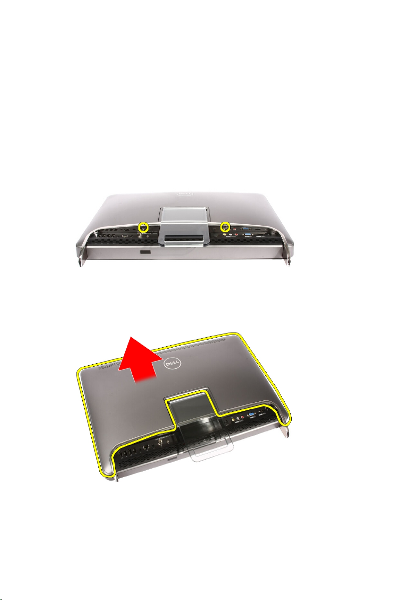
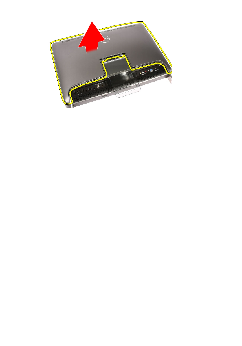
Removing The Cover
1. Follow the procedures in
2. Remove the two screws securing the back cover to the computer.
3. Slide the back cover away from the stand.
Before Working Inside Your Computer
.
4. Remove the back cover.
11
Page 12
Installing The Cover
1. Place the back cover on the computer.
2. Slide the back cover towards the stand.
3. Install the two screws that secure the back cover to the computer.
4. Follow the procedures in
After Working Inside Your Computer
.
12
Page 13
Front Stand 3
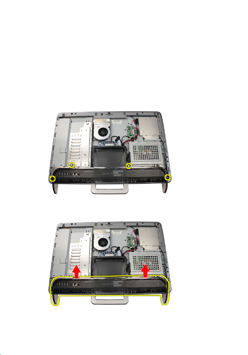
Removing The Front Stand
1. Follow the procedures in
2. Remove the
3. Remove the screws that secure the front stand to the computer.
4. Fold the back stand as far as it will go and then lift the front stand out of the
computer.
cover
Before Working Inside Your Computer
.
.
5. Remove the screws securing the I/O bracket to the front stand.
13
Page 14
6. Remove the I/O panel.
Installing The Front Stand
1. Place the I/O panel on the front stand.
2. Replace the screws securing the I/O bracket to the front stand.
3. Fold the back stand as far as it will go and then place the front stand on the
computer
4. Replace the screws that secure the front stand to the computer.
5. Replace the
6. Follow the procedures in
14
cover
.
After Working Inside Your Computer
.
Page 15
Back Stand Cover 4
Removing The Back Stand Cover
1. Follow the procedures in
2. Remove the
3. Remove the
4. Push the back stand to its maximum extent.
5. Slide the stand cover through the stand and remove the back stand cover
from the computer.
cover
front stand
Before Working Inside Your Computer
.
.
.
15
Page 16

Installing The Back Stand Cover
1. Push the back stand to its maximum extent.
2. Slide the stand cover through the stand and install the back stand cover on
the computer.
3. Replace the
4. Follow the procedures in
cover
.
After Working Inside Your Computer
.
16
Page 17
Back Stand 5
Removing The Back Stand
1. Follow the procedures in
2. Remove the
3. Remove the
4. Remove the
5. Remove the screws that secure the back stand to the computer.
6. Tilt the back stand forward to disengage the tab securing it to the chassis.
cover
front stand
back stand cover
Before Working On Your Computer
.
.
.
.
17
Page 18
7. Remove the back stand.
Installing The Back Stand
1. Place the back stand on the computer.
2. Tilt the stand forward to engage the tab securing it to the chassis.
3. Replace the screws that secure the back stand to the computer.
4. Follow the procedures in
After Working Inside Your Computer
.
18
Page 19
Convertor Board 6
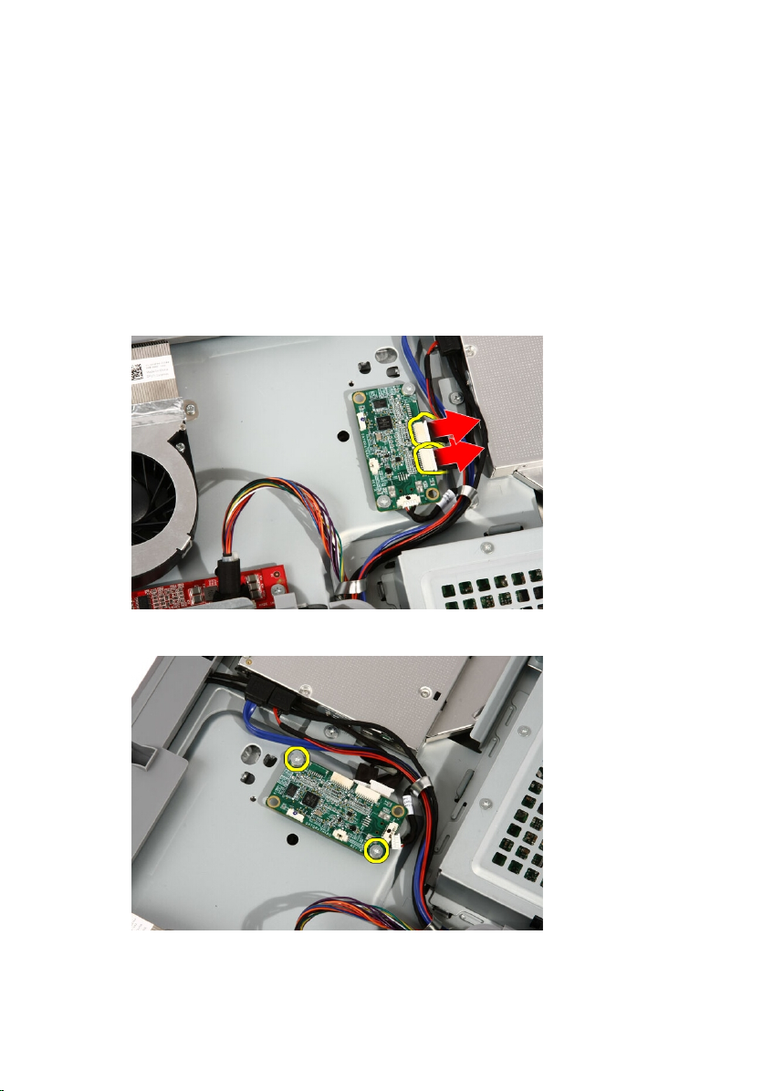
Removing The Convertor Board
1. Follow the procedures in
2. Remove the
3. Disconnect the cables from the convertor board.
4. Remove the screws that secure the convertor board to the computer.
cover
Before Working Inside Your Computer
.
.
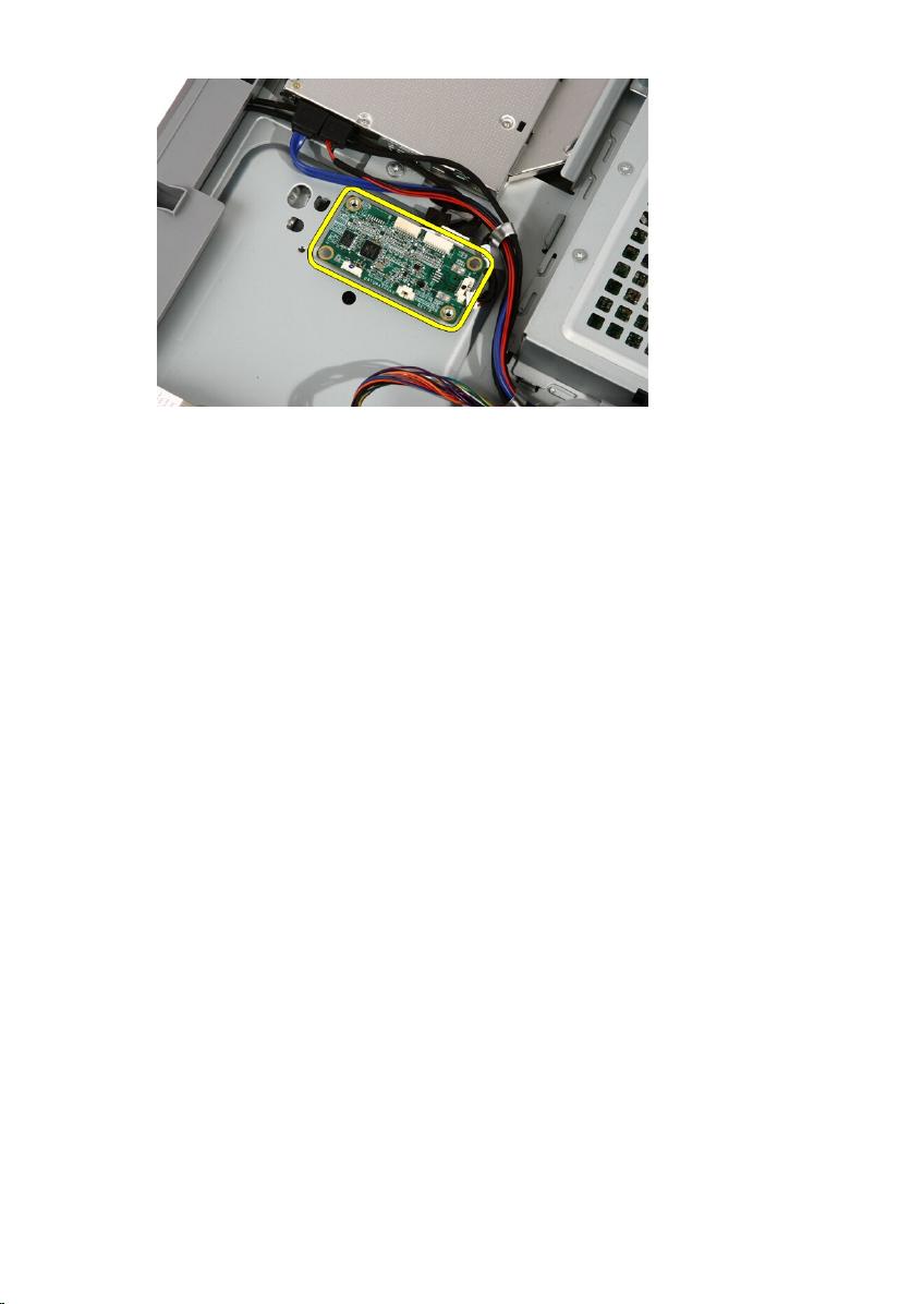
5. Remove the convertor board from the computer.
19
Page 20
Installing The Convertor Board
1. Place the convertor board on the computer.
2. Replace the screws that secure the convertor board to the computer.
3. Connect the display and power cables to the convertor board.
cover
4. Replace the
5. Follow the procedures in
.
After Working Inside Your Computer
.
20
Page 21
Touch-Control Board 7
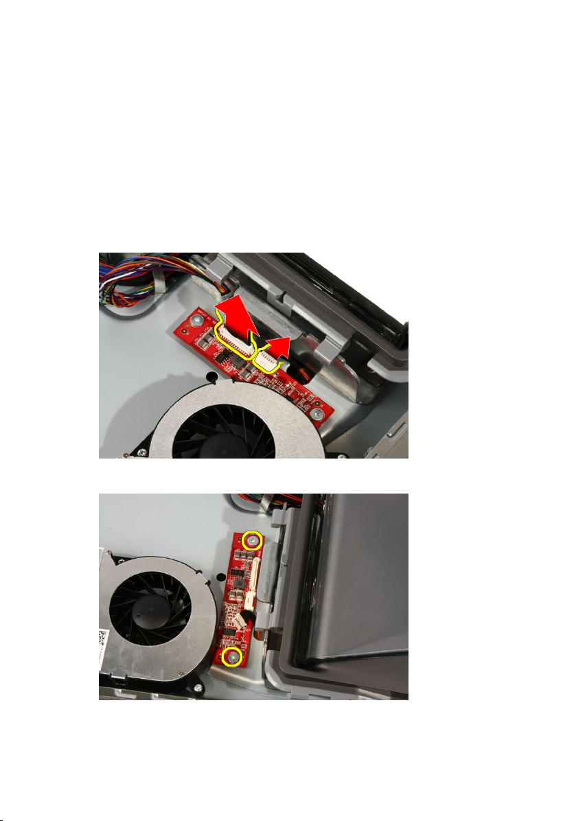
Removing The Touch-Control Board
1. Follow the procedures in
2. Remove the
3. Disconnect the cables from the touch-control board.
4. Remove the screws that secure the touch-control board.
cover
Before Working On Your Computer
.
.
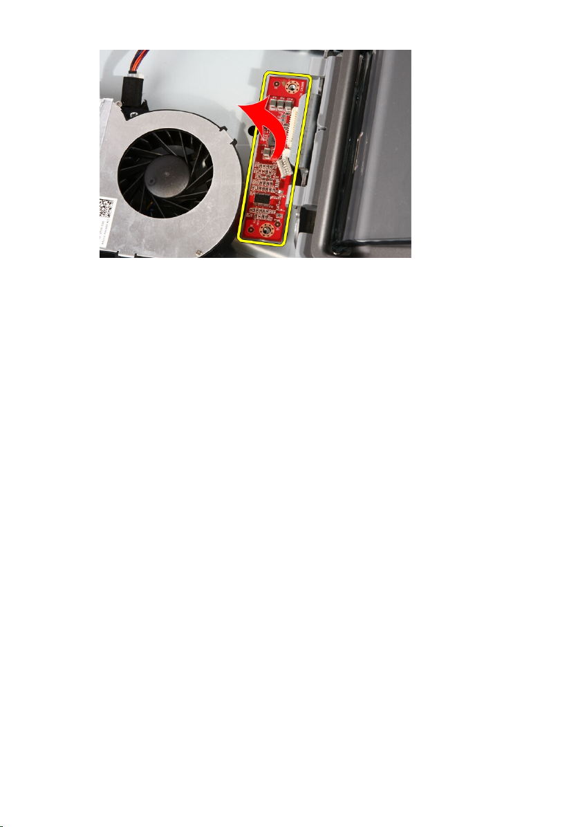
5. Remove the touch-control board from the computer.
21
Page 22
Installing The Touch-Control Board
1. Place the touch-control board on the computer.
2. Replace the screws that secure the touch-control board.
3. Connect the cables to the touch-control board.
cover
4. Replace the
5. Follow the procedures in
.
After Working Inside Your Computer
.
22
Page 23
Hard Drive 8
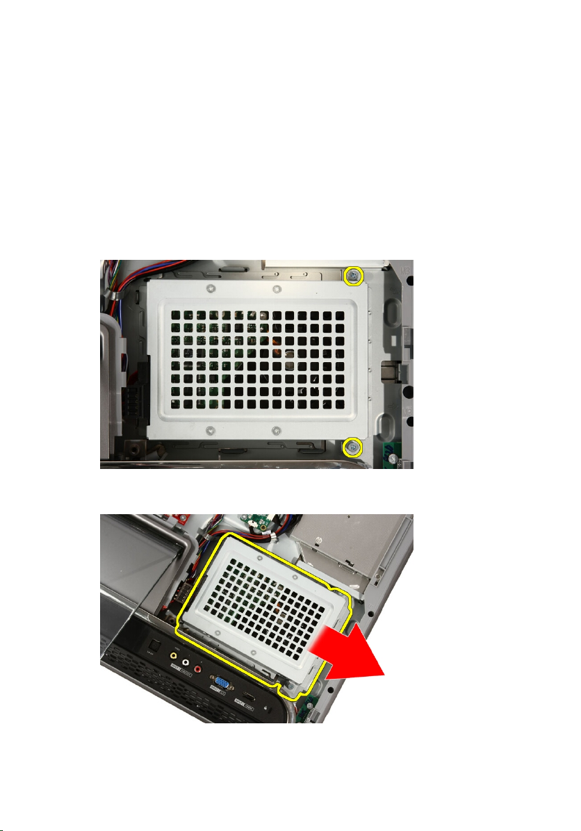
Removing The Hard Drive
1. Follow the procedures in
2. Remove the
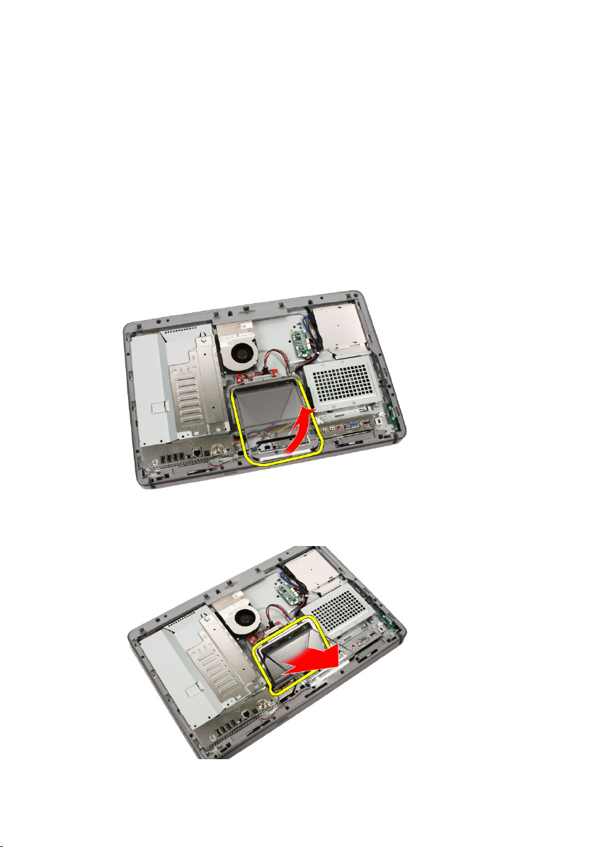
3. Loosen the captive screws that secure the hard drive cage to the
computer.
4. Slide the hard drive bracket away from the computer to release the tabs
from the computer.
cover
Before Working Inside Your Computer
.
.
5. Disconnect the power cable and SATA cable.
23
Page 24
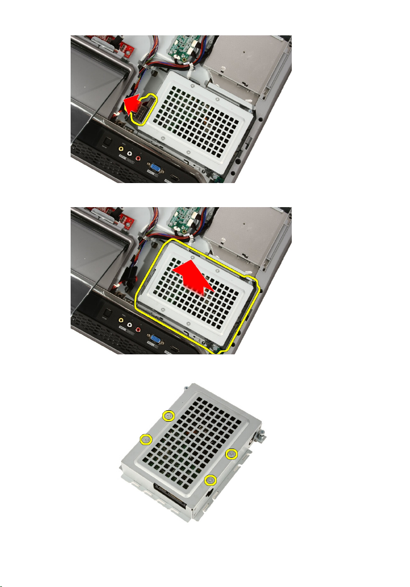
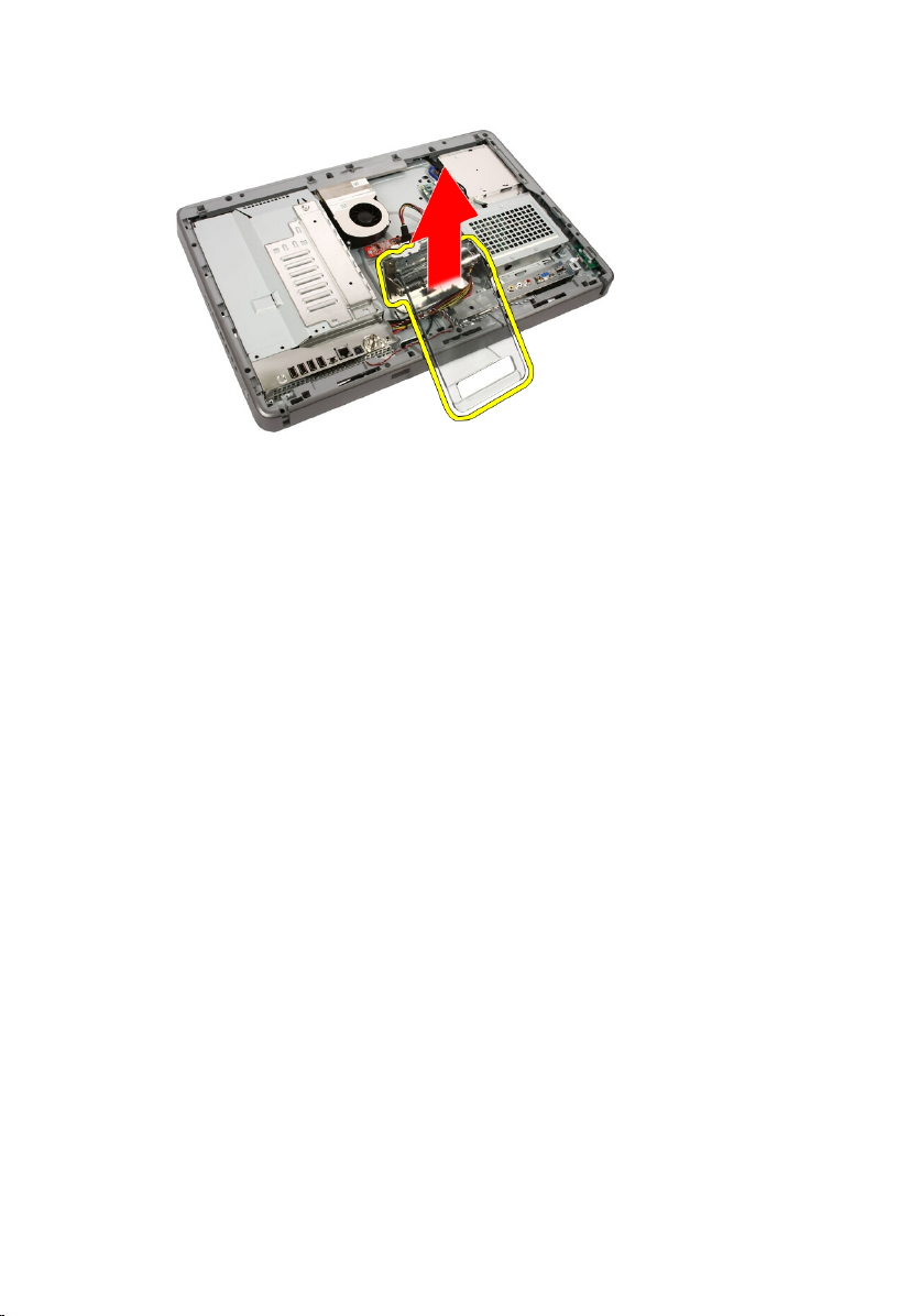
6. Lift the hard drive out of the computer.
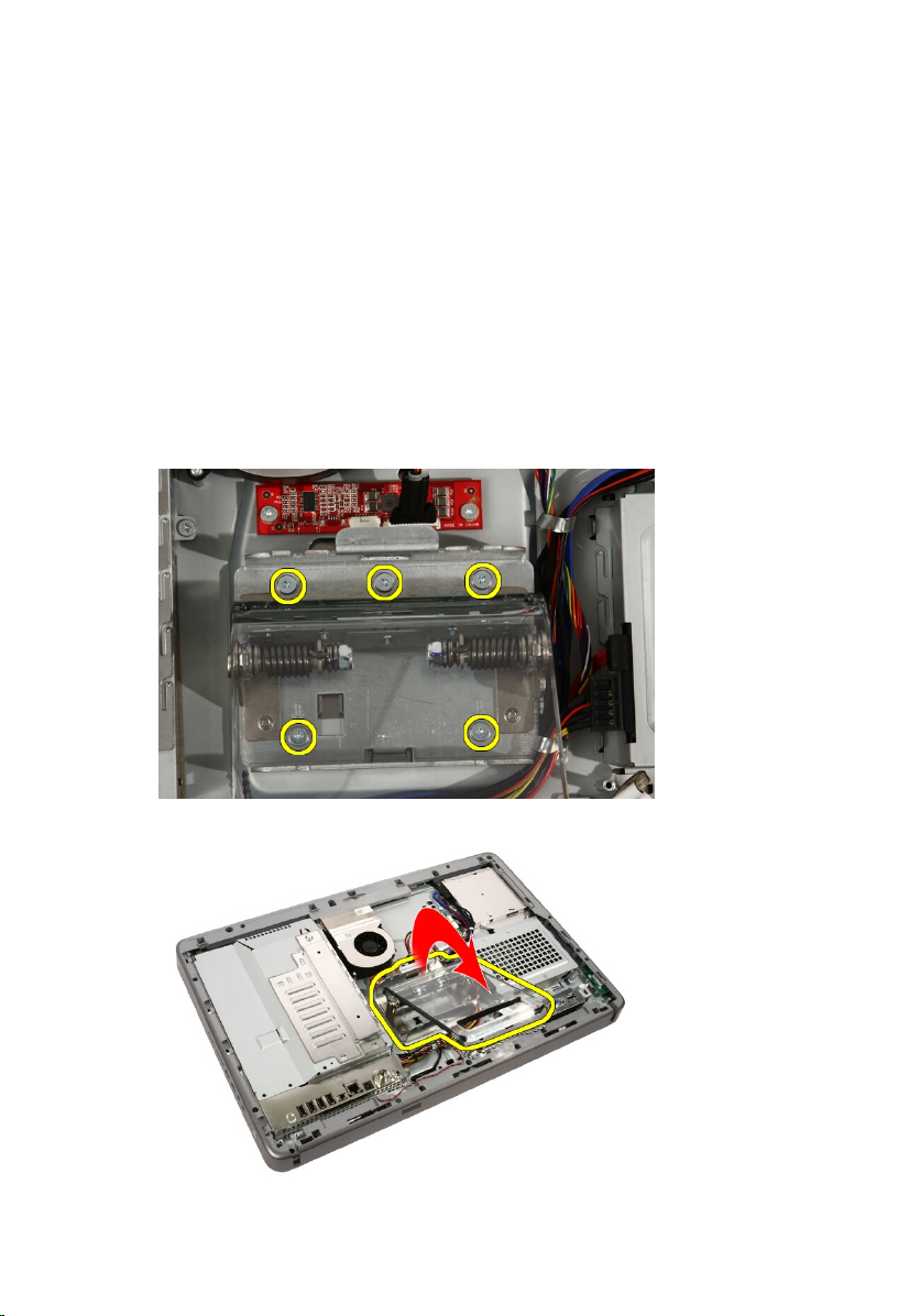
7. Remove the screws that secure the hard drive to the hard drive bracket.
24
Page 25
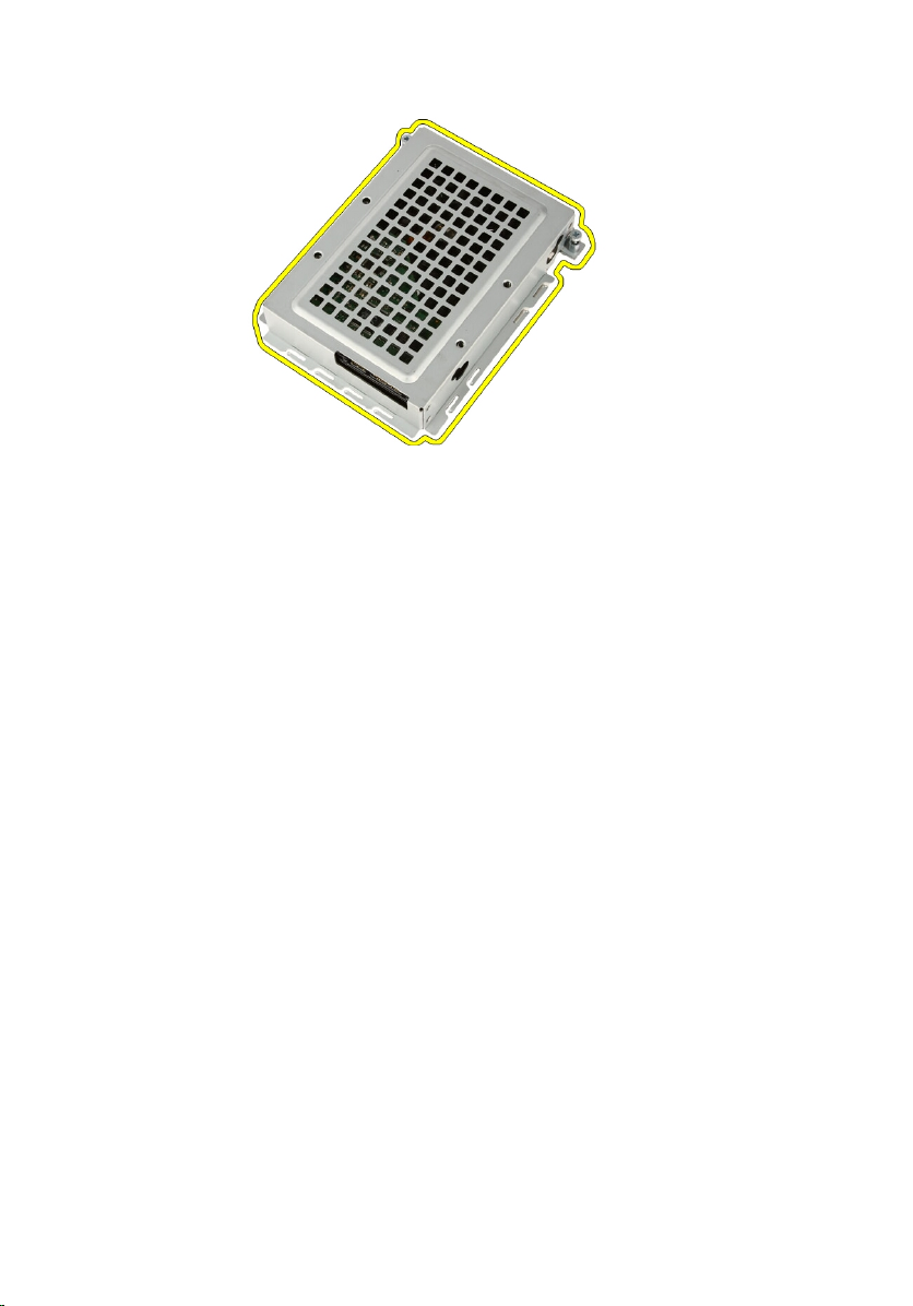
8. Lift the hard drive bracket from the hard drive.
Installing The Hard Drive
1. Place the hard drive bracket on the hard drive.
2. Replace the screws securing the hard drive to the hard drive bracket.
3. Place the hard drive on the computer.
4. Connect the power cable and SATA cable.
5. Slide the hard drive bracket towards the computer to secure the tabs to the
computer.
6. Tighten the captive screws that secure the hard drive cage to the
computer.
7. Replace the
8. Follow the procedures in
cover
.
After Working Inside Your Computer
.
25
Page 26

26
Page 27
Memory 9
Removing The Memory
1. Follow the procedures in
2. Remove the
3. Remove the screw that secures the memory cover to the computer.
4. Slide the memory cover towards the top of the computer.
cover
Before Working Inside Your Computer
.
.
5. Remove the memory cover from the computer.
27
Page 28
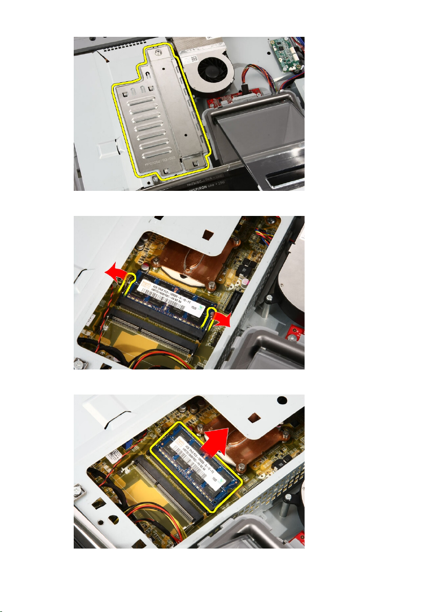
6. Spread the retainer clips until the memory pops out.
7. Pull out the memory out of the computer.
28
Page 29

Installing The Memory
1. Insert the memory into the memory slot at a 45–degree angle and press
down till it clicks into place.
2. Replace the memory cover and slide it towards the bottom of the computer.
3. Replace the screw that secures the memory cover to the computer.
4. Replace the
5. Follow the procedures in
cover
.
After Working Inside Your Computer
.
29
Page 30

30
Page 31

System Board Shield 10
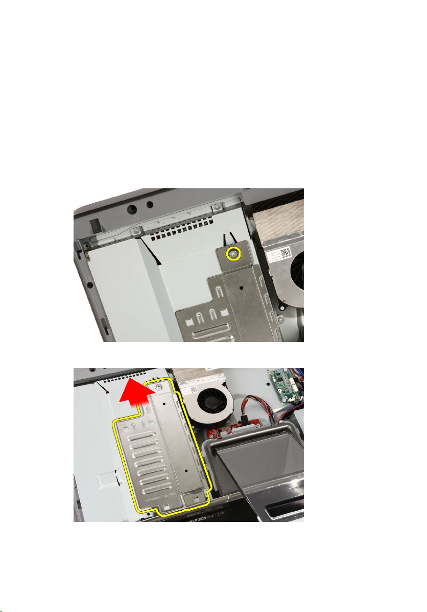
Removing The System Board Shield
1. Follow the procedures in
2. Remove the
3. Remove the
4. Remove the single screw along the bottom edge of the system board shield.
5. Remove the screws that secure the upper part of the system board shield.
cover
front stand
Before Working Inside Your Computer
.
.
.
6. Carefully tilt the system board shield and place it next to the computer.
31
Page 32

7. Disconnect the TV Tuner cable and IR Blaster cable.
8. Remove the system board shield from the computer.
32
Page 33

Installing The System Board Shield
1. Connect the TV Tuner cable and IR Blaster cable to the system board.
2. Carefully tilt the system board shield and place it on the system board.
3. Replace the screws that secure the upper part of the system board shield.
4. Replace the single screw along the bottom edge of the system board shield.
5. Replace the
6. Replace the
7. Follow the procedures in
front stand
cover
.
.
After Working Inside Your Computer
.
33
Page 34

34
Page 35

Coin-Cell Battery 11
Removing The Coin-Cell Battery
1. Follow the procedures in
2. Remove the
3. Remove the
4. Remove the
5. Press the coin-cell battery release tab till the battery pops out.
6. Remove the coin-cell battery from the socket.
cover
front stand
system board shield
Before Working Inside Your Computer
.
.
.
.
35
Page 36

Installing The Coin-Cell Battery
1. Place the coin-cell battery into it's socket.
2. Press the battery till it snaps into the coin-cell battery socket.
3. Replace the
4. Replace the
5. Replace the
6. Follow the procedures in
system board shield
front stand
cover
.
.
After Working Inside Your Computer
.
.
36
Page 37

Wireless Local Area Network
(WLAN) Card 12
Removing The WLAN Card
1. Follow the procedures in
2. Remove the
3. Remove the
4. Remove the
5. Disconnect the antenna cables.
6. Remove the screws that secure the WLAN card to the computer.
cover
front stand
system board shield
Before Working Inside Your Computer
.
.
.
.
37
Page 38

7. Pull the WLAN card out and remove it from the computer.
Installing The WLAN Card
1. Insert the WLAN card into the socket at a 45–degree angle.
2. Press down the WLAN card and replace the screw that secures the WLAN
card to the system board.
3. Connect the antenna cables. Connect the black cable and white cable to
the connector marked with a black and white triangle respectively.
4. Replace the
5. Replace the
6. Replace the
7. Follow the procedures in
38
system board shield
front stand
cover
.
.
.
After Working Inside Your Computer
.
Page 39

Optical Drive 13
Removing The Optical Drive
1. Follow the procedures in
2. Remove the
3. Disconnect the SATA and power cables from the optical drive.
4. Remove the screws that secure the optical drive to the computer.
cover
Before Working On Your Computer
.
.
5. Slide the optical drive out of the computer.
39
Page 40

6. Pry the bezel off the optical drive, to use on the replacement optical drive.
40
Page 41

Installing The Optical Drive
1. Push the bezel onto the optical drive.
2. Slide the optical drive into your computer.
3. Replace the screws that secure the optical drive to the computer.
4. Connect the SATA and power cables from the optical drive.
5. Replace the
6. Follow the procedures in
cover
.
After Working Inside Your Computer
.
41
Page 42

42
Page 43

Middle Bezel 14
Removing The Middle Bezel
1. Follow the procedures in
2. Remove the
3. Remove the
4. Remove the
5. Remove the screws that secure the middle bezel to the computer. The
screws are marked M3 as shown in the image below.
6. Work the middle bezel loose from the chassis.
cover
front stand
system board shield
Before Working On Your Computer
.
.
.
.
43
Page 44

7. If needed, carefully pry the middle bezel up a little, near the ports on the
right side of the computer. The tabs on the bottom of the middle bezel
attach to the chassis here.
8. Tilt the frame up at an angle to loosen the snap tabs from the chassis.
44
Page 45

9. Remove the middle bezel.
Installing The Middle Bezel
1. Place the middle bezel on the computer.
2. Press the middle bezel into the computer till all the tabs snap into place.
3. Replace the screws that secure the middle bezel to the computer.
4. Replace the
5. Replace the
6. Replace the
7. Follow the procedures in
system board shield
front stand
cover
.
.
.
After Working Inside Your Computer
.
45
Page 46

46
Page 47

Speaker 15
Removing The Speakers
1. Follow the procedures in
2. Remove the
3. Remove the
4. Remove the
5. Disconnect the speaker cable from the system board.
6. Remove the screws that secure the speakers to the system board.
cover
front stand
system board shield
Before Working Inside Your Computer
.
.
.
.
47
Page 48

7. Remove the speakers from the system board.
Installing The Speakers
1. Place the speakers on the system board.
2. Replace the screws that secure the speakers to the system board.
3. Connect the speaker cable to the system board.
4. Replace the
5. Replace the
6. Replace the
7. Follow the procedures in
system board shield
front stand
cover
.
.
After Working Inside Your Computer
.
.
48
Page 49

Video Card Fan 16
Removing The Video Card Fan
1. Follow the procedures in
2. Remove the
3. Remove the
4. Remove the
5. Disconnect the video card fan cable from the system board.
6. Remove the screws that secure the video card fan to the computer.
cover
front stand
system board shield
Before Working Inside Your Computer
.
.
.
.
49
Page 50

7. Peel back the tape sealing the video card fan to the video card heat sink.
8. Remove the video card fan from the computer.
Installing The Video Card Fan
1. Place the video card on the computer and paste the tape to seal the video
card fan to the video card heat sink.
2. Replace the screws that secure the video card fan to the computer.
3. Connect the video card fan cable to the system board.
4. Replace the
5. Replace the
6. Replace the
7. Follow the procedures in
50
system board shield
front stand
cover
.
.
.
After Working Inside Your Computer
.
Page 51

Video Card And Heat Sink 17
Removing The MXM Video Card And Heat Sink
1. Follow the procedures in
2. Remove the
3. Remove the
4. Remove the
5. Remove the
6. Remove the screws that secure the MXM card and heat sink to the system
board
The card will pop out at an angle.
7. Remove the MXM video card and heat sink out of the socket.
cover
front stand
system board shield
video card fan
Before Working On Your Computer
.
.
.
.
.
51
Page 52

8. Remove the screws that secure the heat sink to the MXM video card.
9. Pull the heat sink away from the MXM video card.
52
Page 53

10. Pull the MXM video card away from the base plate.
Installing The MXM Video Card And Heat Sink
1. Place the video card on the base plate.
2. Place the heat sink on the video card.
3. Replace the screws that secure the heat sink to the video card.
4. Place the video card and heat sink into it's socket.
5. Replace the screws that secure the video card and heat sink to the system
board.
6. Replace the
7. Replace the
8. Replace the
9. Replace the
10. Follow the procedures in
video card fan
.
system board shield
front stand
cover
.
.
After Working Inside Your Computer
.
.
53
Page 54

54
Page 55

Thermal Fan 18
Removing The Processor Fan
1. Follow the procedures in
2. Remove the
3. Remove the
4. Remove the
5. Disconnect the processor fan cable from the system board.
6. Remove the screws that secure the processor fan to the system board.
cover
front stand
system board shield
Before Working Inside Your Computer
.
.
.
.
55
Page 56

7. Peel back the tape sealing the processor fan to the heat sink.
8. Remove the processor fan from the computer.
Installing The Processor Fan
1. Place the processor fan on the heat sink and paste the tape that secures
the processor fan to the heat sink.
2. Replace the screws that secure the processor fan to the system board.
3. Connect the processor fan cable to the system board.
4. Replace the
5. Replace the
6. Replace the
7. Follow the procedures in
56
system board shield
front stand
cover
.
.
.
After Working Inside Your Computer
.
Page 57

Heat Sink 19
Removing The Processor Heat Sink
1. Follow the procedures in
2. Remove the
3. Remove the
4. Remove the
5. Remove the
6. Remove the
7. Remove the
8. Remove the screws that secure the heat sink to the computer.
9. Remove the screws that secure the heat sink to the system board.
cover
front stand
system board shield
video card fan
video card and heat sink assembly
processor fan
Before Working Inside Your Computer
.
.
.
.
.
.
.
57
Page 58

10. Remove the heat sink from the computer.
58
Page 59

Installing The Processor Heat Sink
1. Place the heat sink on the computer and replace the screws that secure
the heat sink to the system board.
2. Replace the screws that secure the heat sink to the computer.
3. Replace the
4. Replace the
5. Replace the
6. Replace the
7. Replace the
8. Replace the
9. Follow the procedures in
processor fan
video card fan
.
.
video card and heat sink assembly
system board shield
front stand
cover
.
.
.
After Working Inside Your Computer
.
.
59
Page 60

60
Page 61

Processor 20
Removing The Processor
1. Follow the procedures in
2. Remove the
3. Remove the
4. Remove the
5. Remove the
6. Remove the
7. Remove the
8. Remove the
9. Unlock the process screw by turning it counter-clockwise until it clicks in
the unlocked position.
cover
front stand
system board shield
video card fan
video card and heat sink assembly
processor fan
processor heat sink
Before Working On Your Computer
.
.
.
.
.
.
.
.
10. Remove the processor from the socket on the system board.
61
Page 62

Installing The Processor
1. The processor is notched at one end with a triangle marking. The same
marking is also notched on the processor socket. Align these two notches
and slide the processor into the socket and it should slide in nicely and fit
into the socket without any force.
2. Lock the processor into the socket by turning the screw clockwise until it
clicks into the locked position.
3. Replace the
4. Replace the
5. Replace the
6. Replace the
7. Replace the
8. Replace the
9. Replace the
10. Follow the procedures in
processor heat sink
processor fan
video card fan
.
.
.
video card and heat sink assembly
system board shield
front stand
cover
.
.
.
After Working Inside Your Computer
.
.
62
Page 63

System Board 21
Removing The System Board
1. Follow the procedures in
2. Remove the
3. Remove the
4. Remove the
5. Remove the
6. Remove the
7. Remove the
8. Remove the
9. Remove the
10. Remove the
11. Disconnect the AV cable from the system board.
cover
front stand
system board shield
WLAN card
video card fan
video card and heat sink assembly
processor fan
processor heat sink
processor
Before Working On Your Computer
.
.
.
.
.
.
.
.
.
.
12. Disconnect the SATA cable from the system board.
63
Page 64

13. Open the cable clamp and free the cables.
14. Disconnect the two cables.
64
Page 65

15. Disconnect the five cables.
16. Disconnect the speaker cable.
17. Remove the mounting post for the video card fan.
65
Page 66

18. Remove the screws that secure the system board to the computer.
19. Push the system board towards the middle of the computer and lift it out of
the computer.
66
Page 67

20. Remove the system board from the computer.
21. Remove the thermal pads located on the chassis under the system board.
67
Page 68

Installing The System Board
1. Replace the thermal pads under the system board.
2. Replace the two thermal pads under the memory slots.
3. Replace the screws that secure the system board to the computer.
4. Replace the mounting post for the video card fan.
5. Connect the speaker cable.
6. Connect the five cables.
7. Connect the two cables.
8. Tie the cables using a cable clamp for better cable management.
9. Connect the SATA cables to the system board.
10. Connect the AV cable to the system board.
11. Replace the
12. Replace the
13. Replace the
14. Replace the
15. Replace the
16. Replace the
17. Replace the
18. Replace the
19. Follow the procedures in
processor heat sink
processor fan
video card fan
.
.
.
video card and heat sink assembly
memory
system board shield
front stand
cover
.
.
.
.
After Working Inside Your Computer
.
.
68
Page 69

Front Bezel 22
Removing The Front Bezel
1. Follow the procedures in
2. Remove the
3. Remove the
4. Remove the
5. Remove the
6. Remove the
7. Remove the
8. Remove the
9. Remove the
10. Remove the
11. Remove the
12. Remove the
13. Route the Bluetooth cable through the routing slot on the chassis.
cover
front stand
system board shield
WLAN card
video card fan
video card and heat sink assembly
processor fan
processor heat sink
processor
system board
middle bezel
Before Working On Your Computer
.
.
.
.
.
.
.
.
.
.
.
.
14. Un-thread the IR cable and camera cable.
69
Page 70

15. Remove the screws that secure the front bezel to the chassis. The screws
are marked with an arrow as shown in the image below.
16. Hold the assembly together and carefully turn it over.
70
Page 71

17. Hold the panels tightly so the display panel does not fall and get damaged.
18. Lay the assembly on the soft surface.
71
Page 72

19. Peel the tape connecting the web camera to the chassis.
20. Locate the two tabs that secure the bezel.
21. Pull the tab to release it.
72
Page 73

22. Push the tab at the bottom edge of the bezel toward the outside the
computer and release it.
23. Lift the bottom edge of the bezel a little.
73
Page 74

24. Carefully route the Bluetooth cable out through the routing slot.
25. Carefully route out the IR cable and camera cable out through the routing
slot.
74
Page 75

26. Lift the front bezel off the chassis.
75
Page 76

Installing The Front Bezel
1. Place the front bezel on the chassis.
2. Carefully route in the IR cable and camera cable out through the routing
slot.
3. Carefully route-in the Bluetooth cable through the routing slot.
4. Press the bezel till it snaps into the chassis.
5. Hold the assembly together and carefully turn it over.
6. Replace the screws that secure the front bezel to the chassis. The screws
are marked with an arrow.
7. Thread the IR cable and camera cable.
8. Route the bluetooth cable through the routing slot on the chassis.
9. Replace the
10. Replace the
11. Replace the
12. Replace the
13. Replace the
14. Replace the
15. Replace the
16. Replace the
17. Follow the procedures in
processor
processor heat sink
processor fan
video card fan
.
.
.
video card and heat sink assembly
system board shield
front stand
cover
.
.
.
After Working Inside Your Computer
.
.
76
Page 77

Display Panel 23
Removing The Display Panel
1. Follow the procedures in
2. Remove the
3. Remove the
4. Remove the
5. Remove the
6. Remove the
7. Remove the
8. Remove the
9. Remove the
10. Remove the
11. Remove the
12. Remove the
13. Remove the
14. Remove the screws on both sides of the display panel that secure the
display panel to the chassis.
cover
front stand
system board shield
WLAN card
video card fan
video card and heat sink assembly
processor fan
processor heat sink
processor
system board
middle bezel
front bezel
Before Working Inside Your Computer
.
.
.
.
.
.
.
.
.
.
.
.
.
15. Tilt the panel up. Keep holding it so it will not slip down and get damaged.
77
Page 78

16. As you lift the panel, check that all four cables are free of their routing
holes.
17. Remove the display panel.
78
Page 79

79
Page 80

Installing The Display Panel
1. Route all the cables through their routing slots.
2. Place the display panel on the frame.
3. Replace the screws that secure the display panel to the chassis.
4. Route the IR and Bluetooth cables through their respective routing holes.
5. Press the bezel on to the display till all the tabs snap into place.
6. Replace the web camera.
7. Carefully turn the assembly over.
8. Replace the screws that secure the front bezel to the chassis.
9. Route the IR cable and camera cable thorough their routing slots.
10. Connect the camera cables to the DSP board.
11. Connect the display power cable to the converter.
12. Route the Bluetooth cable through the routing slot.
13. Replace the
14. Replace the
15. Replace the
16. Replace the
17. Replace the
18. Replace the
19. Replace the
20. Replace the
21. Replace the
22. Replace the
23. Follow the procedures in
80
front bezel
.
middle bezel
processor
.
processor heat sink
processor fan
video card fan
video card and heat sink assembly
system board shield
front stand
cover
.
.
.
.
.
.
.
.
After Working Inside Your Computer
.
Page 81

Speaker Cover 24
Removing The Speaker Cover
1. Follow the procedures in
2. Remove the
3. Remove the
4. Remove the
5. Remove the
6. Remove the
7. Remove the
8. Remove the
9. Remove the
10. Remove the
11. Remove the
12. Remove the
13. Remove the
14. Locate the speaker panel.
cover
.
front stand
.
system board shield
WLAN card
video card fan
video card and heat sink assembly
processor fan
processor heat sink
processor
.
system board
middle bezel
front bezel
Before Working On Your Computer
.
.
.
.
.
.
.
.
.
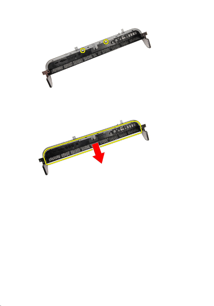
15. Push the two snap tabs toward the outside of the computer to release the
cover.
81
Page 82

16. Lift the speaker cover off the chassis.
82
Page 83

Installing The Speaker Cover
1. Push the speaker cover into its slot on the chassis till the tabs snap into
place.
2. Replace the
3. Replace the
4. Replace the
5. Replace the
6. Replace the
7. Replace the
8. Replace the
9. Replace the
10. Replace the
11. Replace the
12. Follow the procedures in
front bezel
middle bezel
processor
processor heat sink
processor fan
video card fan
.
.
.
.
.
.
video card and heat sink assembly
system board shield
front stand
cover
.
.
.
After Working Inside Your Computer
.
.
83
Page 84

84
Page 85

Bluetooth Card 25
Removing The Bluetooth Card
1. Follow the procedures in
cover
2. Remove the
3. Remove the
4. Remove the
5. Remove the
6. Remove the
7. Remove the
8. Remove the
9. Remove the
10. Remove the
11. Remove the
12. Remove the
13. Remove the
14. Locate the Bluetooth card.
.
front stand
.
system board shield
WLAN card
.
video card fan
video card and heat sink assembly
processor fan
processor heat sink
processor
.
system board
middle bezel
front bezel
Before Working On Your Computer
.
.
.
.
.
.
.
.
15. Remove the Mylar cover.
85
Page 86

16. Remove the screws that secure the Bluetooth card to the front bezel.
17. Remove the Bluetooth card with its cable.
86
Page 87

Installing The Bluetooth Card
1. Place the Bluetooth card at it's location on the front bezel.
2. Replace the screws that secure the Bluetooth card to the front bezel.
3. Replace the Mylar cover.
4. Replace the
5. Replace the
6. Replace the
7. Replace the
8. Replace the
9. Replace the
10. Replace the
11. Replace the
12. Replace the
13. Replace the
14. Follow the procedures in
front bezel
system board
processor heat sink
processor fan
video card fan
.
.
.
.
.
video card and heat sink assembly
WLAN card
system board shield
front stand
cover
.
.
.
.
After Working Inside Your Computer
.
.
87
Page 88

88
Page 89

Camera 26
Removing The Web Camera
1. Follow the procedures in
cover
2. Remove the
3. Remove the
4. Remove the
5. Remove the
6. Remove the
7. Remove the
8. Remove the
9. Remove the
10. Remove the
11. Remove the
12. Remove the
13. Remove the
14. Locate the camera board.
.
front stand
.
system board shield
WLAN card
video card fan
video card and heat sink assembly
processor fan
processor heat sink
processor
.
system board
middle bezel
front bezel
.
Before Working Inside Your Computer
.
.
.
.
.
.
.
.
.
15. Remove the screws that secure the camera board to the front bezel.
89
Page 90

16. Remove the camera board along with the cable.
90
Page 91

Installing The Web Camera
1. Place the camera at it's location on the front bezel.
2. Replace the screws that secure the security camera board to the front
bezel.
3. Replace the
4. Replace the
5. Replace the
6. Replace the
7. Replace the
8. Replace the
9. Replace the
10. Replace the
11. Replace the
12. Replace the
13. Replace the
14. Follow the procedures in
front bezel
middle bezel
system board
processor heat sink
processor fan
video card fan
.
.
.
.
.
.
video card and heat sink assembly
WLAN card
system board shield
front stand
cover
.
.
.
After Working Inside Your Computer
.
.
91
Page 92

92
Page 93

AV Cable 27
Removing The AV Cable
1. Follow the procedures in
2. Remove the
3. Remove the
4. Remove the
5. Remove the
6. Remove the
7. Remove the
8. Remove the
9. Remove the
10. Remove the
11. Remove the
12. Remove the
13. Remove the
14. Remove the
15. Remove the tapes that secure the AV cable, as shown in the image.
cover
front stand
system board shield
WLAN card
video card fan
video card and heat sink assembly
processor fan
processor heat sink
processor
system board
middle bezel
front bezel
display panel
Before Working Inside Your Computer
.
.
.
.
.
.
.
.
.
.
.
.
.
.
93
Page 94

Installing The AV Cable
1. Replace the one large tape and one small tape securing the AV cable, as
shown in the image.
2. Replace the
3. Replace the
4. Replace the
5. Replace the
6. Replace the
7. Replace the
8. Replace the
9. Replace the
10. Replace the
11. Replace the
12. Replace the
13. Follow the procedures in
front bezel
middle bezel
system board
processor heat sink
processor fan
video card fan
.
.
.
.
.
.
video card and heat sink assembly
WLAN card
system board shield
front stand
cover
.
.
.
After Working Inside Your Computer
.
.
94
Page 95

Antenna 28
Removing The Antenna
1. Follow the procedures in
cover
2. Remove the
3. Remove the
4. Remove the
5. Remove the
6. Remove the
7. Remove the
8. Remove the
9. Remove the
10. Remove the
11. Remove the
12. Remove the
13. Remove the
14. Remove the
15. Locate the antenna cables.
.
front stand
.
system board shield
WLAN card
.
video card fan
video card and heat sink assembly
processor fan
processor heat sink
processor
.
system board
middle bezel
front bezel
.
.
display panel
Before Working Inside Your Computer
.
.
.
.
.
.
.
.
16. Work the cables through the routing hole and remove them from the clips.
Then turn the chassis over.
95
Page 96

17. Locate the cables and antennae.
18. Remove the screws that secure the antenna to the chassis.
96
Page 97

19. Peel up the tape securing the cables. Then turn the chassis over.
20. Peel up the metal tape connecting the antenna to the chassis.
21. Remove the antenna with their cables.
97
Page 98

Installing The Antenna
1. Place the antenna on its location on the chassis and paste it to the chassis
using the metal tape.
2. Turn the chassis over. Paste the cables using the metal tape.
3. Replace the screws that secure the antenna to the chassis.
4. Route the cables through the routing slots, and engage the cables to the
clips.
5. Replace the
6. Replace the
7. Replace the
8. Replace the
9. Replace the
10. Replace the
11. Replace the
12. Replace the
13. Replace the
14. Replace the
15. Follow the procedures in
98
front bezel
middle bezel
processor
processor heat sink
processor fan
video card fan
video card and heat sink assembly
system board shield
front stand
cover
.
.
.
.
.
.
.
.
.
.
After Working Inside Your Computer
.
Page 99

Specifications 29
Specifications
NOTE: Offerings may vary by region. For more information regarding the
configuration of your computer, click Start (or Start in Windows XP) Help and
Support, and then select the option to view information about your computer.
System Information
System Chipset Intel HM57 chipset
DMA Channels two 82C37 DMA controllers with seven
independently programmable channels
Interrupt Levels
BIOS Chip (NVRAM) 2 MB (64 KB)
Processor
Processor type
Total Cache up to 6 MB cache depending on processor
Memory
Speed 1333 MHz
Connectors two DIMM slots
Capacity 1 GB, 2 GB, and 4 GB
Minimum Memory 2 GB
• two cascaded 82C59 with 15 interrupts
• integrated I/O APIC capability with 24
interrupts
• Intel Core i3
• Intel Core i5
• Intel Core i7
• Intel Pentium Dual Core
type
99
Page 100

Memory
Maximum memory 8 GB
Video
Video Type:
Integrated Intel HD Graphics
Discrete ATI Mobility Radeon HD
5470
Video Memory:
Integrated up to 384 MB of shared
video memory
Discrete 1 GB DDR3
Audio
Integrated dual-channel High-Definition audio
Communication
Network adapter network interface card capable of
10/100/1000 Mb/s communication
Wireless
Expansion Bus
Bus Type MXM, SATA 1.0A and 2.0, USB 2.0
Bus Speed PCIe X16
Expansion Cards
Mobile PCI Express Module (MXM) one
Drives
Externally Accessible one 5.25–inch SATA drive bay
100
• internal wireless local area network
(WLAN)
• Bluetooth wireless support
 Loading...