

Page 1

Dell Vostro 15-7570
Owner's Manual
Regulatory Model: P71F
Regulatory Type: P71F001
Page 2

Notes, cautions, and warnings
NOTE: A NOTE indicates important information that helps you make better use of your product.
CAUTION: A CAUTION indicates either potential damage to hardware or loss of data and tells you how to avoid the problem.
WARNING: A WARNING indicates a potential for property damage, personal injury, or death.
© 2017 Dell Inc. or its subsidiaries. All rights reserved. Dell, EMC, and other trademarks are trademarks of Dell Inc. or its subsidiaries. Other trademarks
may be trademarks of their respective owners.
2017 - 09
Rev. A00
Page 3
Chassis
This chapter illustrates the multiple chassis' view along with the ports and connectors and also explains the function hot key combinations.
Topics:
• Front open view
• Left view
• Right view
• Palmrest view
• Back view
• Bottom view
• Keyboards hot key denitions
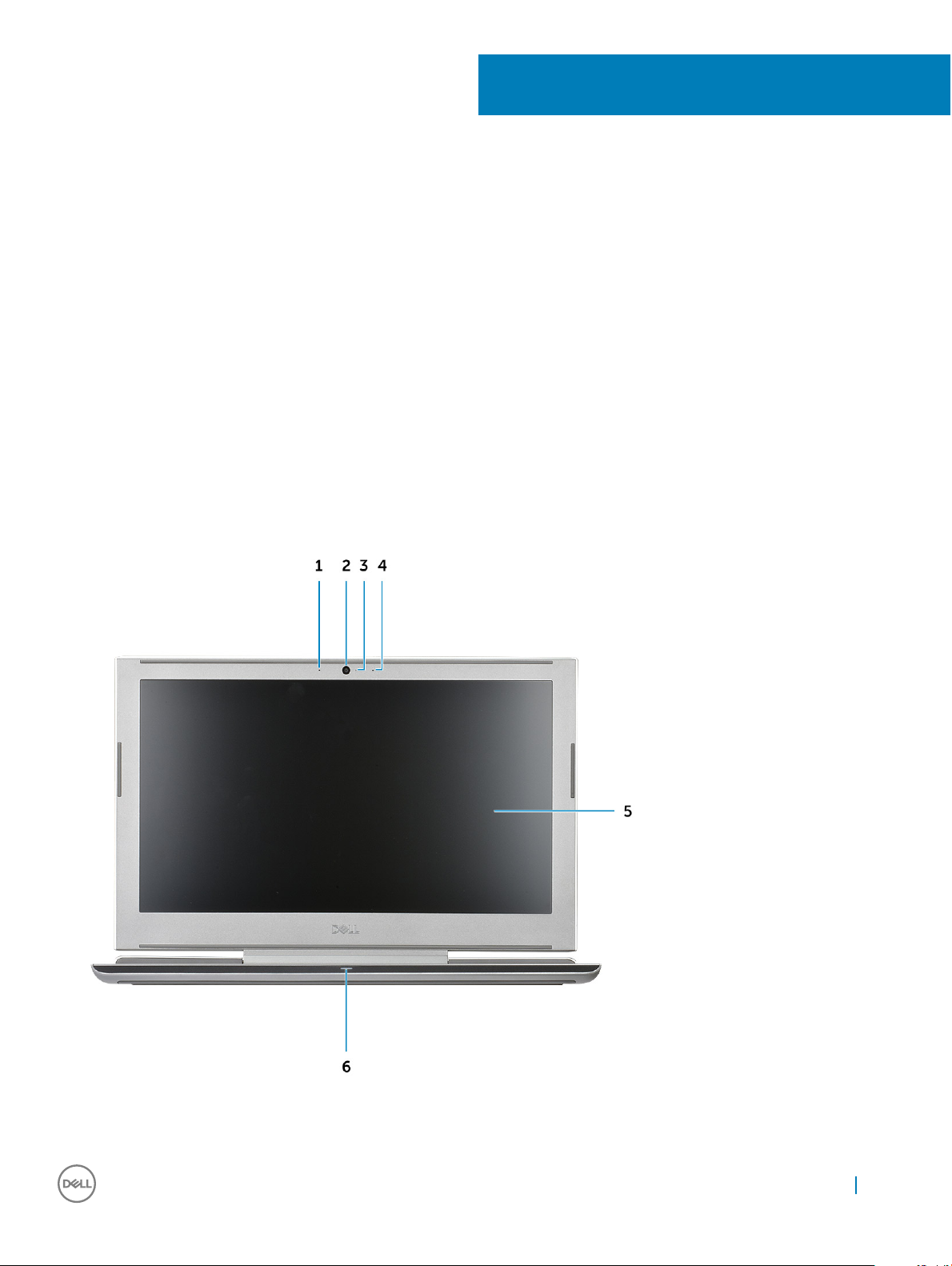
Front open view
1
1
Dual array microphones 2 Camera
Chassis 3
Page 4
3 Camera status light 4 Dual array microphones
5 Display panel 6 LED status light
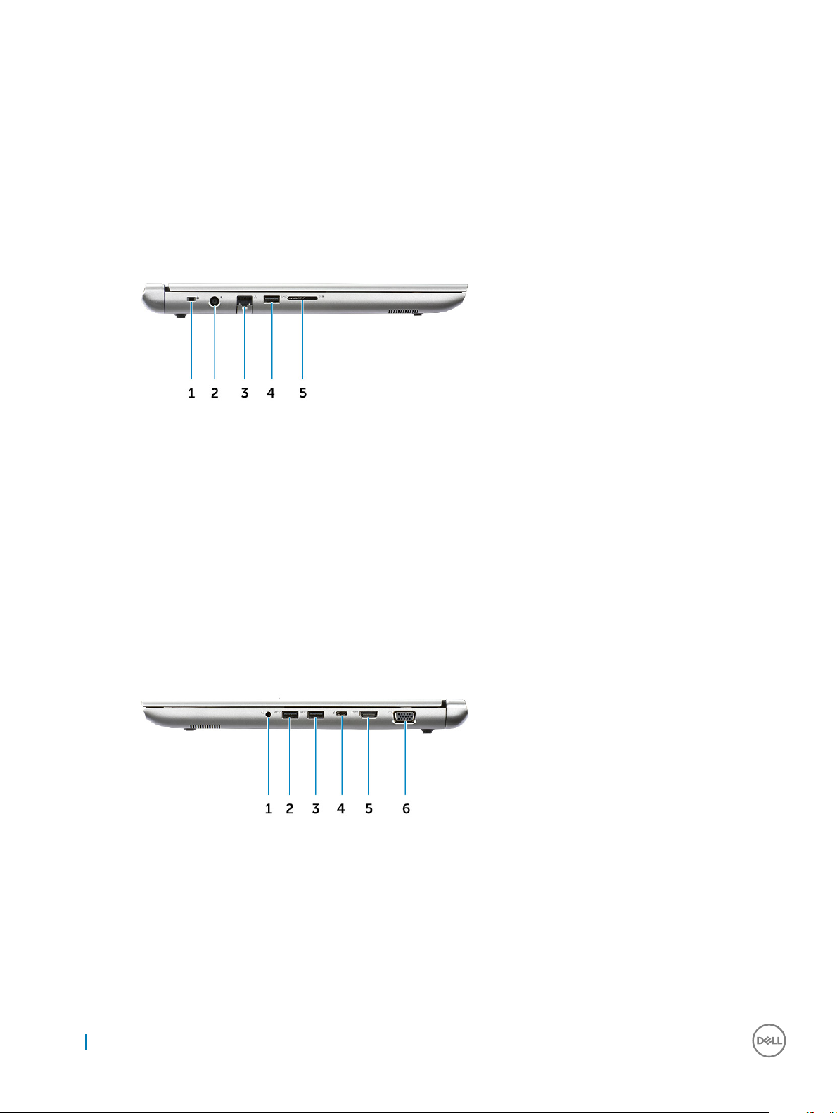
Left view
1 Nobel Wedge lock slot 2 Power connector
3 Network connector 4 USB 3.1 Gen 1 port
5 SD card reader
Right view
1
Headset/Mic port 2 USB 3.1 Gen 1 port
3 USB 3.1 Gen 1 port 4 USB Type-C port with Thunderbolt 3
5 HDMI port 6 VGA port
4 Chassis
Page 5
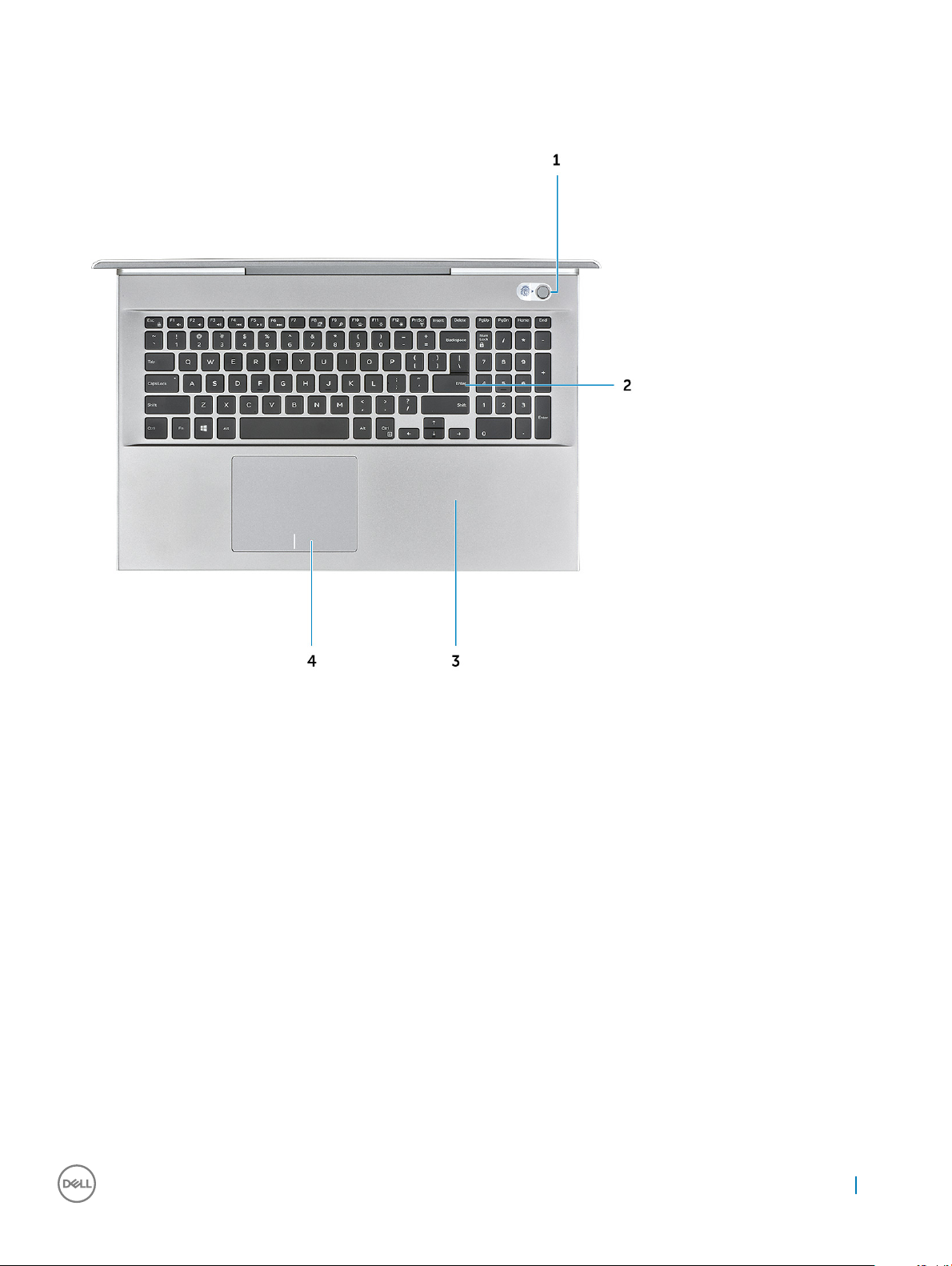
Palmrest view
1 Power button/Fingerprint reader 2 Keyboard
3 Palmrest 4 Touchpad
Chassis 5
Page 6
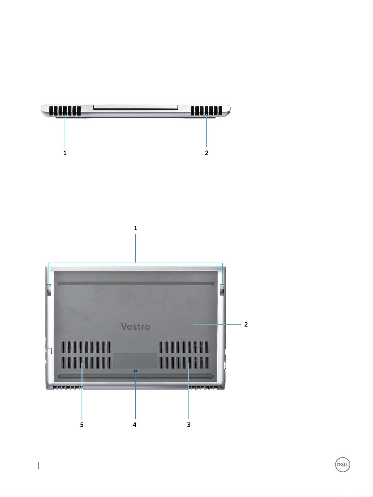
Back view
1 Air vent 2 Air vent
Bottom view
6
Chassis
Page 7

1 Speakers 2 Back cover
3 Air vent 4 Service tag label
5 Air vent
Keyboards hot key denitions
Table 1. Keyboard hot key combination
Fn Key Combination Function
Fn+ESC Fn Toggle
Fn+ F1 Speaker Mute
Fn + F2 Volume Down
Fn + F3 Volume Up
Fn + F4 Previous track
Fn + F5 Play/Pause
Fn + F6 Next track
Fn + F8 Extend display
Fn + F9 Search
Fn + F10 Increase Keyboard Backlight Brightness
(Pressing this function cycles keyboard backlight to the next level in
the sequence: 50%, 100%, o)
Fn + F11 Decrease brightness
Fn + F12 Increase brightness
Fn + PrtScr Turn o/on wireless
Chassis 7
Page 8

Removing and installing components
This section provides detailed information on how to remove or install the components from your computer.
Recommended tools
The procedures in this document require the following tools:
• Phillips #0 screwdriver
• Phillips #1 screwdriver
• Plastic scribe
NOTE: The #0 screw driver is for screws 0-1 and the #1 screw driver is for screws 2-4
Before working inside your computer
1 Ensure that your work surface is at and clean to prevent the computer cover from being scratched.
2 Turn o your computer.
3 If the computer is connected to a docking device (docked), undock it.
4 Disconnect all network cables from the computer (if available).
2
CAUTION
computer.
5 Disconnect your computer and all attached devices from their electrical outlets.
6 Open the display.
7 Press and hold the power button for few seconds, to ground the system board.
CAUTION
8.
CAUTION: To avoid electrostatic discharge, ground yourself by using a wrist grounding strap or by periodically touching
an unpainted metal surface at the same time as touching a connector on the back of the computer.
8 Remove any installed ExpressCards or Smart Cards from the appropriate slots.
: If your computer has an RJ45 port, disconnect the network cable by rst unplugging the cable from your
: To guard against electrical shock unplug your computer from the electrical outlet before performing Step #
After working inside your computer
After you complete any replacement procedure, ensure that you connect external devices, cards, and cables before turning on your
computer.
CAUTION
designed for other Dell computers.
1 Connect any external devices, such as a port replicator or media base, and replace any cards, such as an ExpressCard.
2 Connect any telephone or network cables to your computer.
3 Connect your computer and all attached devices to their electrical outlets.
4 Turn on your computer.
: To avoid damage to the computer, use only the battery designed for this particular Dell computer. Do not use batteries
CAUTION
computer.
: To connect a network cable, rst plug the cable into the network device and then plug it into the
8 Removing and installing components
Page 9
Base cover
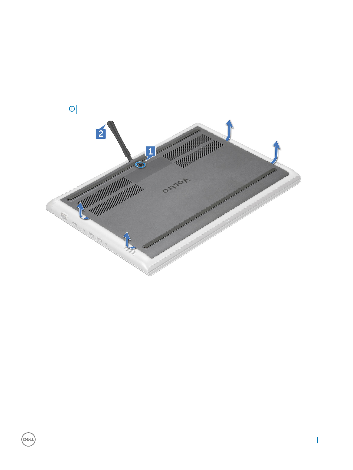
Removing the base cover
1 Follow the procedure in Before working inside your computer.
2 To remove the base cover:
a Loosen the M2.5x2+3.5 captive screws that secure the base cover to the computer [1].
b Pry the base cover from the edge [2].
NOTE: You may need a plastic scribe to pry the base cover from the edge.
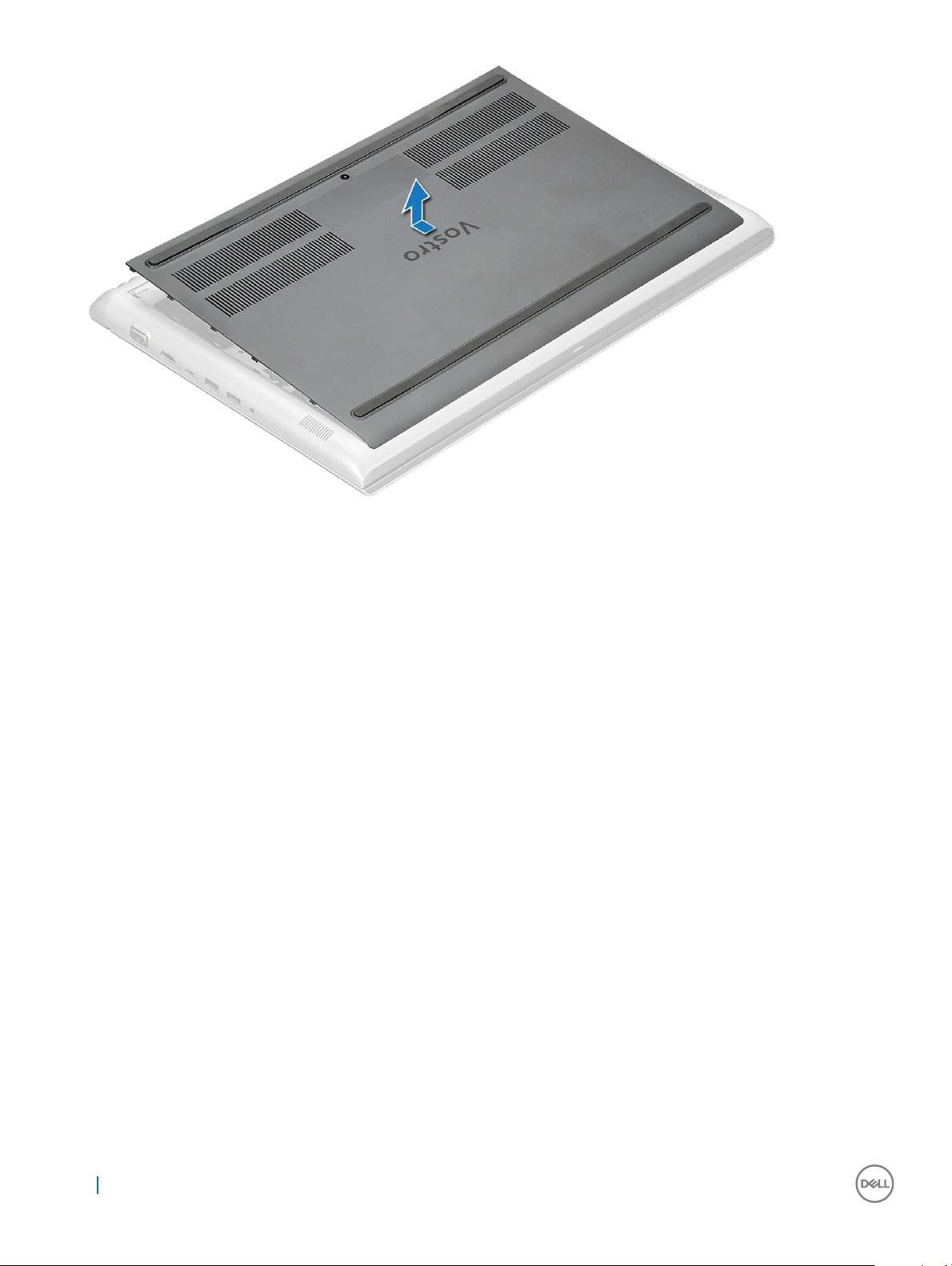
3 Lift the base cover away from the computer.
Removing and installing components
9
Page 10
Installing the base cover
1 Align the base cover with the screw holders on the computer.
2 Press the edges of the cover until it clicks into place.
3 Tighten the M2.5x2+3.5 screws to secure the base cover to the computer.
4 Follow the procedure in After working inside your computer.
Battery
Removing the battery
1 Follow the procedure in Before working inside your computer.
2 Remove the base cover.
3 To remove the battery:
a Disconnect the battery cable from the connector on the system board [1].
b Remove the M2x3L screws that secure the battery to the computer [2].
10
Removing and installing components
Page 11
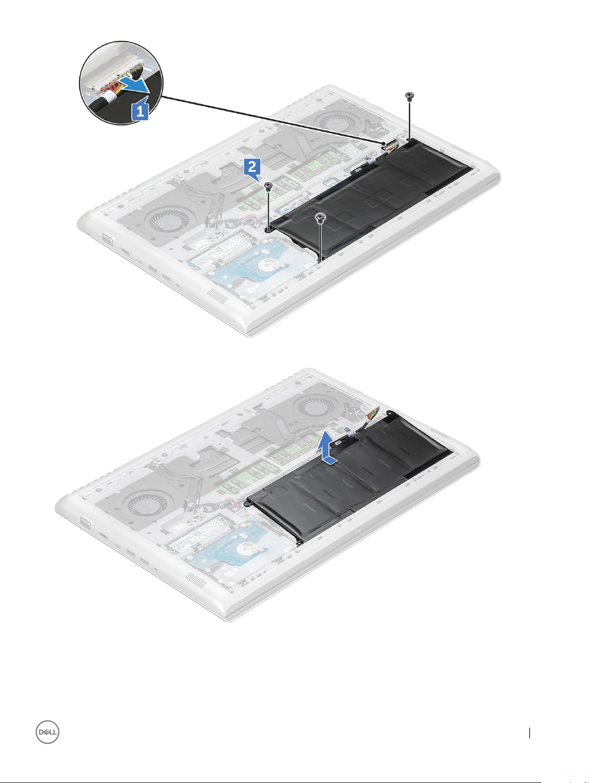
4 Lift the battery away from the computer.
Installing the battery
1 Insert the battery into the slot on the computer.
2 Connect the battery cable to the connector on the battery.
Removing and installing components
11
Page 12
3 Tighten the M2x3L screws to secure the battery to the computer.
4 Install the base cover
5 Follow the procedure in After working inside your computer.
Coin cell battery
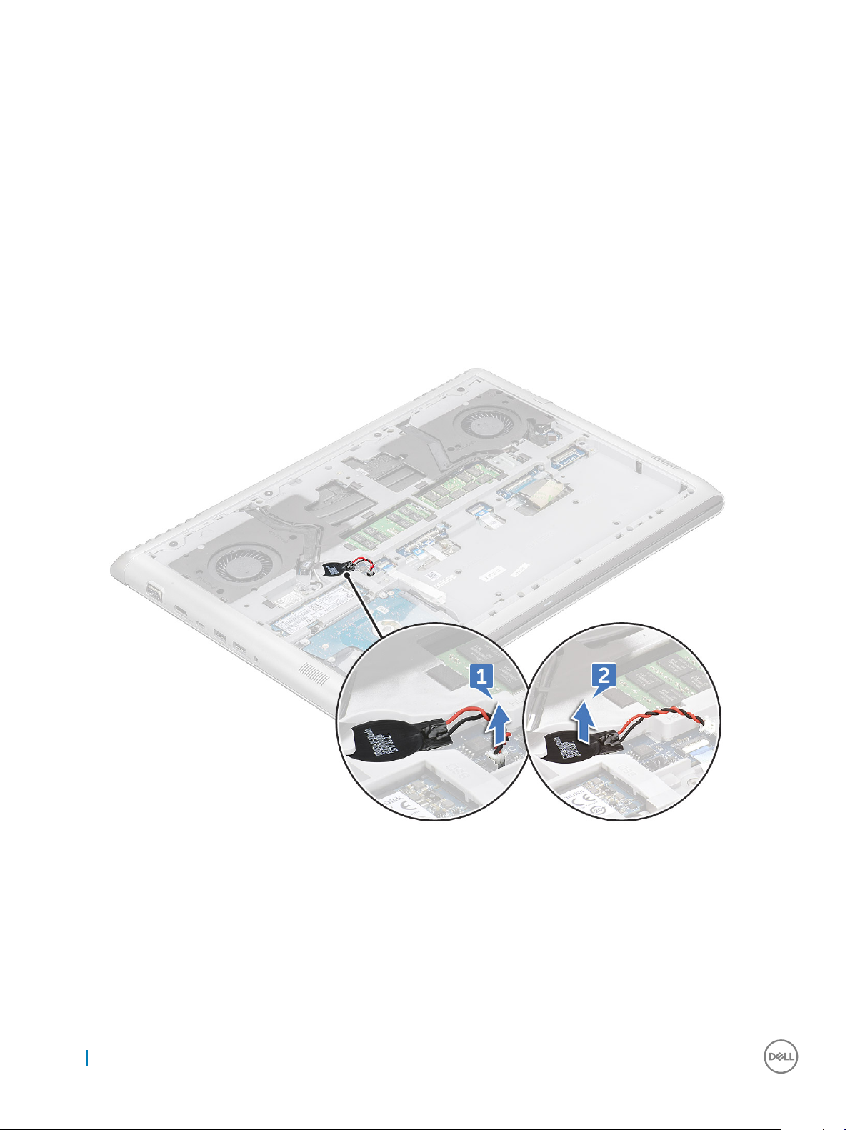
Removing the coin cell battery
1 Follow the procedure in Before working inside your computer.
2 Remove the:
a base cover
b battery
3 To remove the coin cell battery:
a Disconnect the coin cell battery cable from the connector on the system board [1].
b Pry the coin cell battery to release from the adhesive and lift it away from the system board [2].
Installing the coin cell battery
1 Place the coin cell battery into the slot on the system board.
2 Connect the coin cell battery cable to the connector on the system board.
3 Install the:
a battery
b base cover
4 Follow the procedure in After working inside your computer.
12
Removing and installing components
Page 13
Memory modules
Removing the memory module
1 Follow the procedure in Before working inside your computer.
2 Remove the:
a base cover
b battery
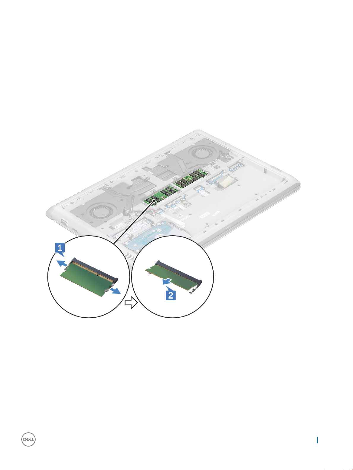
3 To remove the memory module:
a Pry the clips securing the memory module until the memory pops-up [1].
b Lift the memory module away from the connector [2].
Installing the memory module
1 Insert the memory module into the memory module socket until the clips secure the memory module.
2 Install the:
a battery
b base cover
3 Follow the procedure in After working inside your computer.
Removing and installing components
13
Page 14
Hard drive
Removing the hard drive
1 Follow the procedure in Before working inside your computer.
2 Remove the:
a base cover
b battery
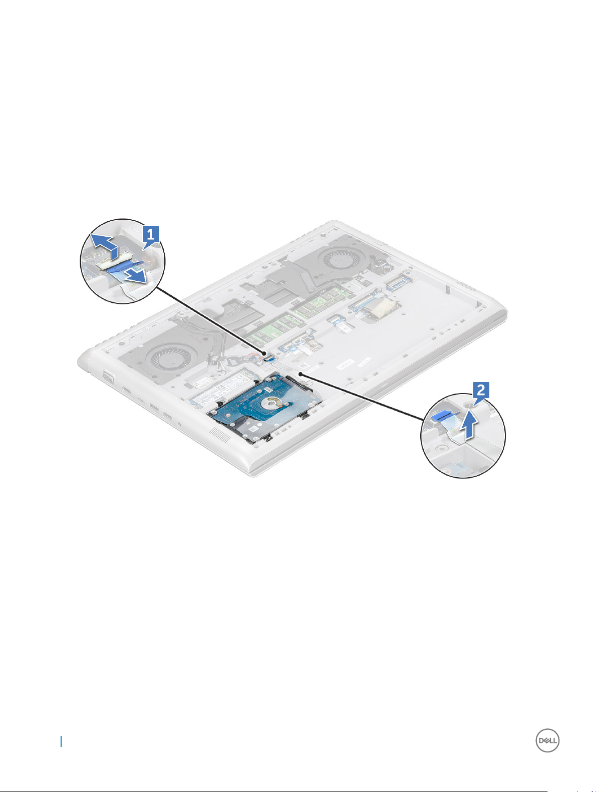
3 To disconnect the cable:
a Lift the latch and disconnect the hard drive cable from the computer [1].
b Pry the hard drive cable to release from the adhesive [2].
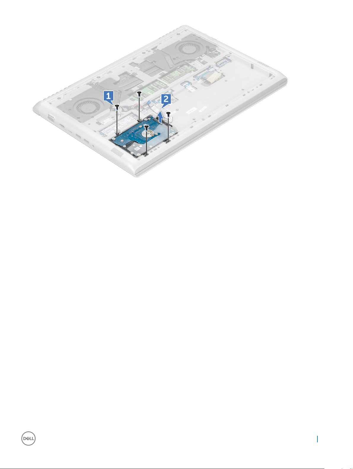
4 To remove the hard drive:
a Remove the M2.5x5L screws that secure the hard drive to the computer [1].
b Lift the hard drive away from the computer [2].
14
Removing and installing components
Page 15
Installing the hard drive
1 Insert the hard drive into the slot on the computer.
2 Replace the M2.5x5L screws to secure the hard drive assembly to the computer.
3 Ax the hard drive cable on the computer.
4 Connect the hard drive cable to the connector on the hard drive and on the system board.
5 Install the:
a battery
b base cover
6 Follow the procedure in After working inside your computer.
Solid State Drive — optional
Removing the M.2 Solid State Drive — SSD
1 Follow the procedure in Before working inside your computer.
2 Remove the:
a base cover
b battery
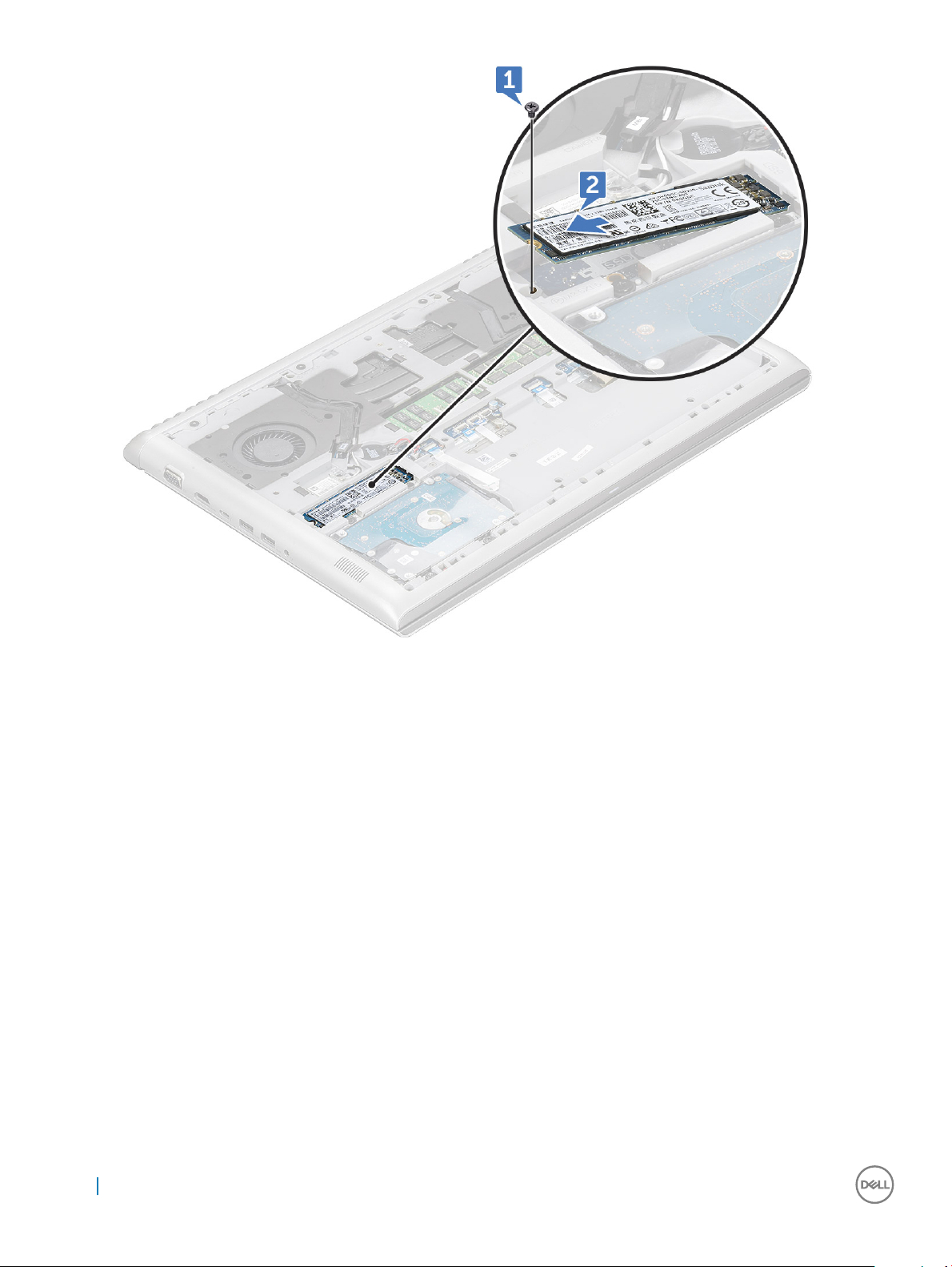
3 To remove the SSD:
a Remove the M3x3L screw that secures the SSD to the computer [1].
b Slide and lift the SSD from the computer [2].
Removing and installing components
15
Page 16
Installing the M.2 Solid State Drive — SSD
1 Insert the SSD into the connector on the computer.
2 Replace the M3x3L screw to secure the SSD to the computer.
3 Install the:
a battery
b base cover
4 Follow the procedure in After working inside your computer.
WLAN card
Removing the WLAN card
1 Follow the procedure in Before working inside your computer.
2 Remove the:
a base cover
b battery
3 To remove the WLAN card:
a Remove the M2x3L screw that secures the WLAN card to the computer [1].
b Remove the tab that secures the WLAN cables [2].
16
Removing and installing components
Page 17
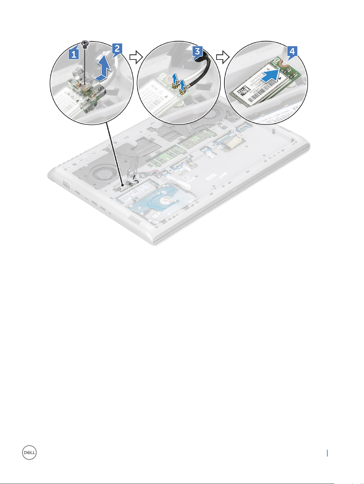
c Disconnect the WLAN cables from the connectors on the WLAN card [3].
d Lift the WLAN card away from the connector [4].
Installing the WLAN card
1 Insert the WLAN card into the slot on the computer.
2 Connect the WLAN cables to the connectors on the WLAN Card.
3 Place the bracket and replace the M2x3L screw to secure it to the computer.
4 Install the:
a battery
b base cover
5 Follow the procedure in After working inside your computer.
Rear cover
Removing the rear cover
1 Follow the procedure in Before working inside your computer.
2 Remove the:
a base cover
b battery
3 To remove the screws:
a Remove the M2x2L(OD7) screws that secure the rear cover to the computer [1].
Removing and installing components
17
Page 18
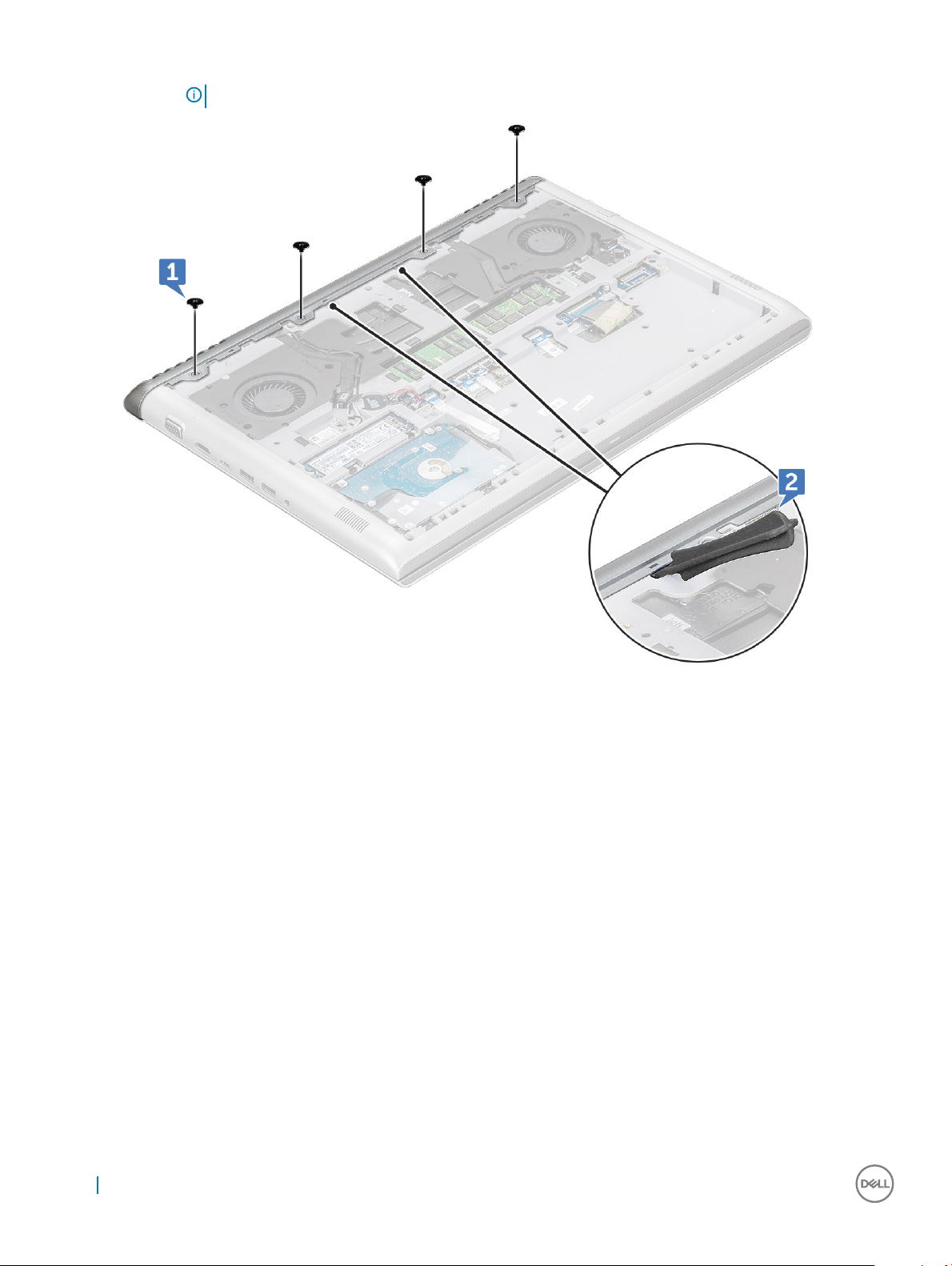
b Pry the rear cover from the edge [2].
NOTE: You may need a plastic scribe to pry the rear cover from the edge.
4 Pry the edges of the rear cover using a plastic scribe.
18
Removing and installing components
Page 19
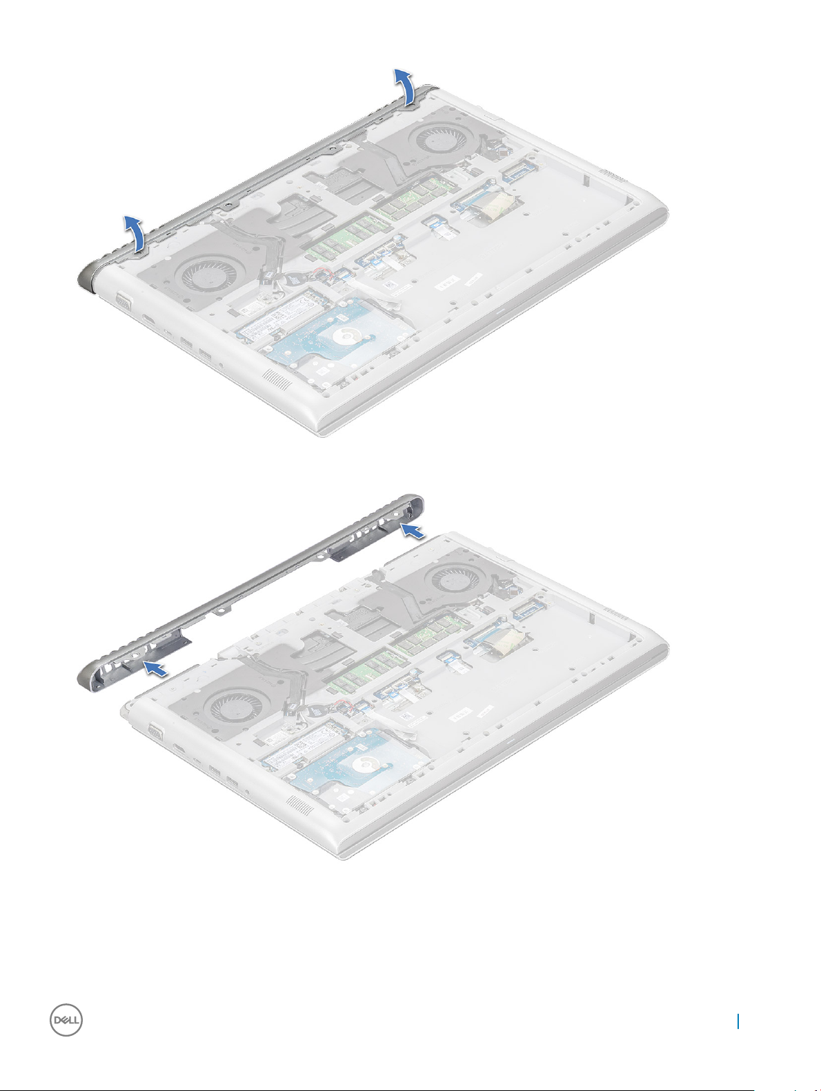
5 Remove the rear cover from the computer.
Installing the rear cover
1 Press the edges of the rear cover until it clicks into place.
2 Tighten the M2x2L(OD7) screws to secure the rear cover to the computer.
Removing and installing components
19
Page 20
3 Install the:
a battery
b base cover
4 Follow the procedure in After working inside your computer.
Back cover
Removing the back cover
1 Follow the procedure in Before working inside your computer.
2 Remove the:
a base cover
b battery
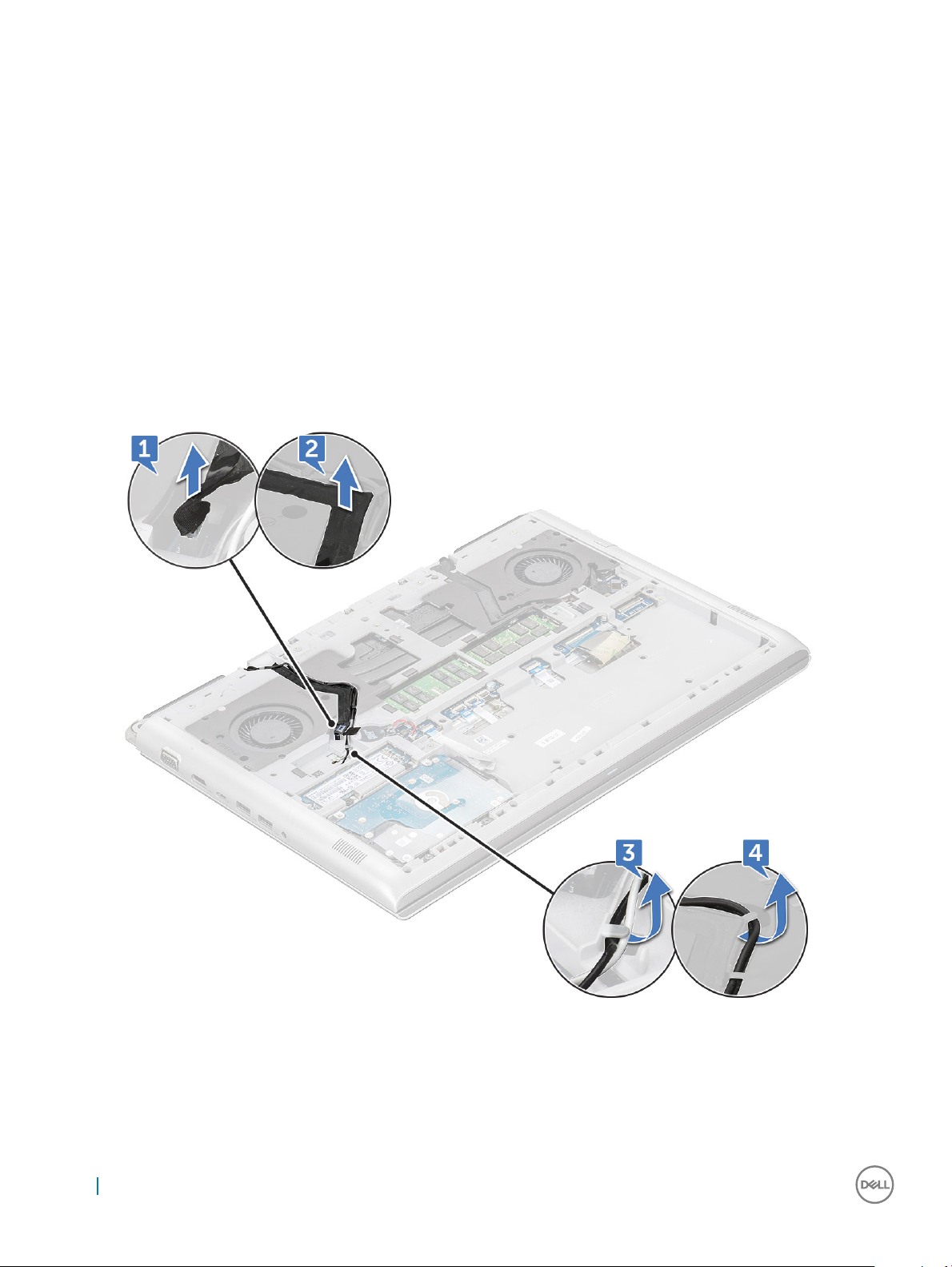
3 To disconnect the cables:
a Disconnect the camera cable and unroute from the routing channel [1, 2].
b Disconnect the WLAN cable and unroute from the routing channel [3, 4].
4 Disconnect the eDP cable:
a Remove the screw (M2x3) that secures the eDP bracket to the computer [1].
b Lift the metal tab from the computer [2].
c Disconnect the eDP cable from the computer [3].
d Unroute the eDP cable from the routing channel [4].
20
Removing and installing components
Page 21
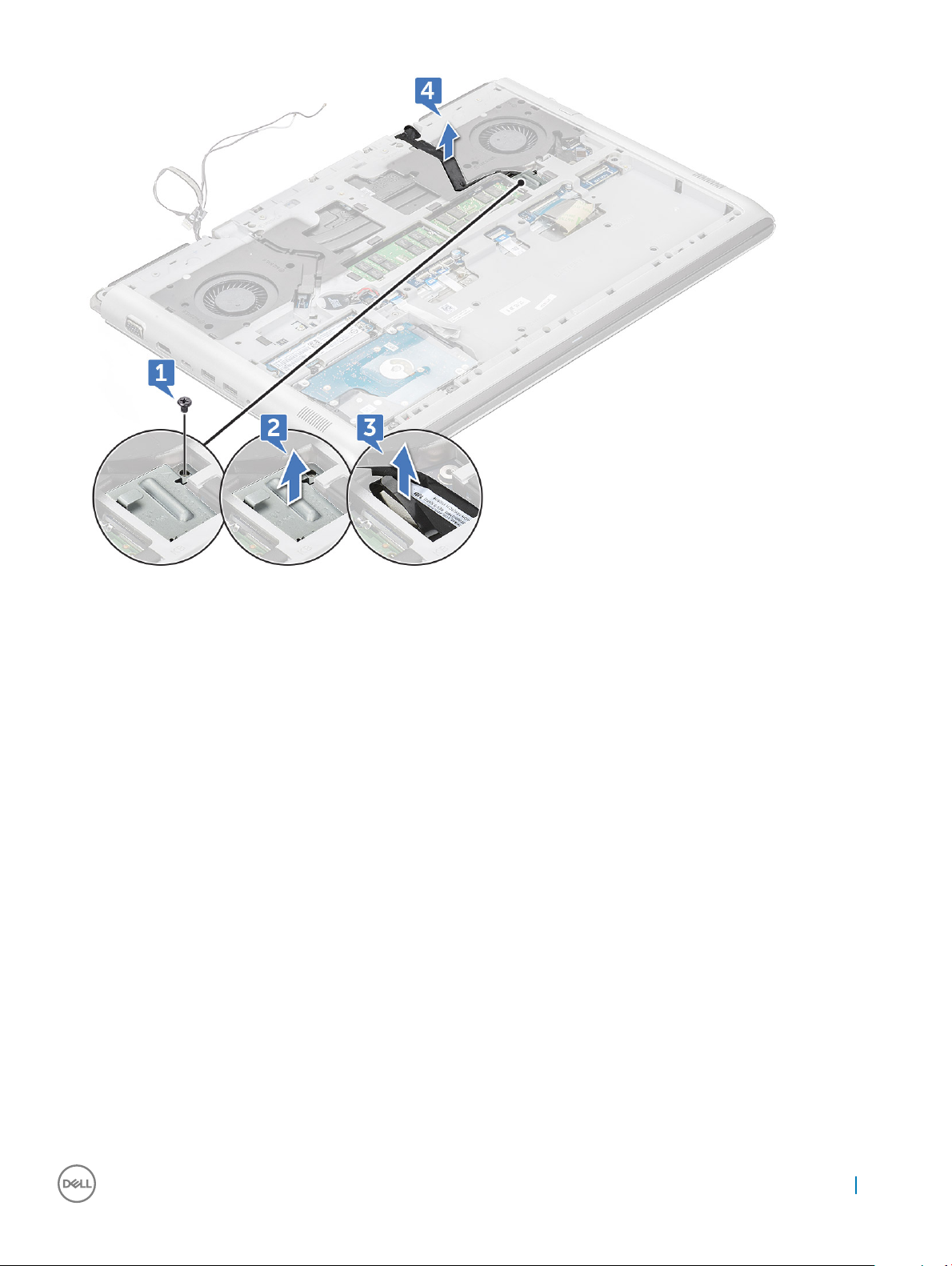
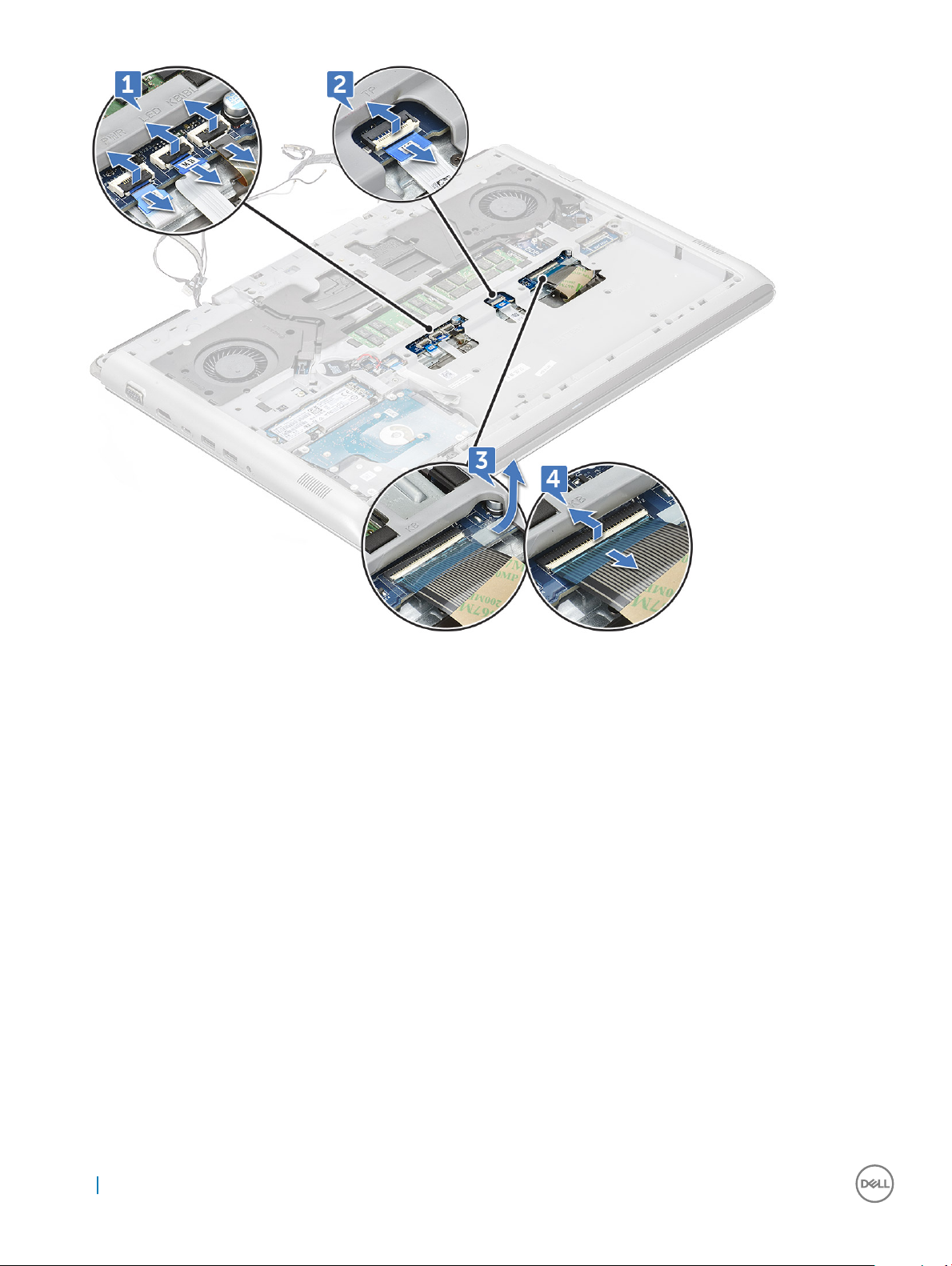
5 Disconnect the following cables:
a Disconnect the Power, LED and Keyboard backlight cable from the connector [1].
b Disconnect the touchpad cable from the connector [2].
c Remove the white adhesive tape and disconnect the keyboard cable from the connector [3, 4].
Removing and installing components
21
Page 22
6 Remove the M2.5xL6 (19) screws that secure the back cover to the computer.
22
Removing and installing components
Page 23
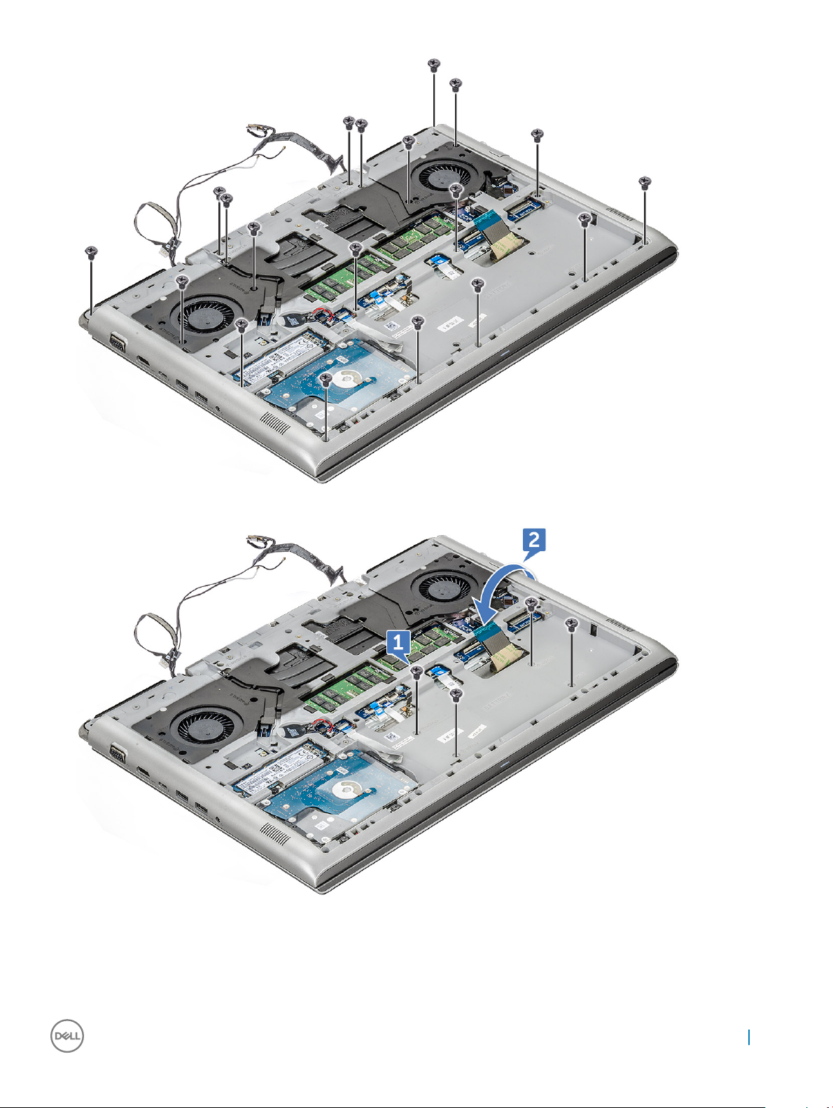
7 Remove the M2L3(4) screws and turn over the system [1, 2].
8 Open the display assembly at 90° angle.
Removing and installing components
23
Page 24
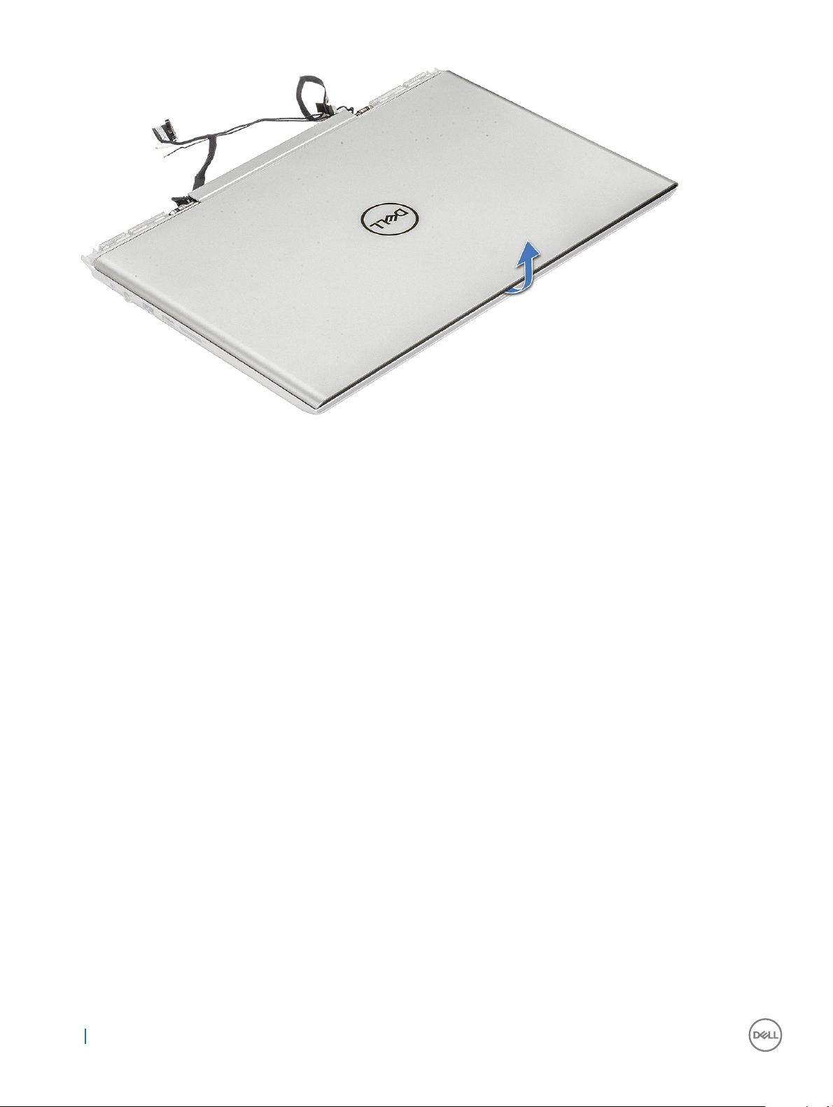
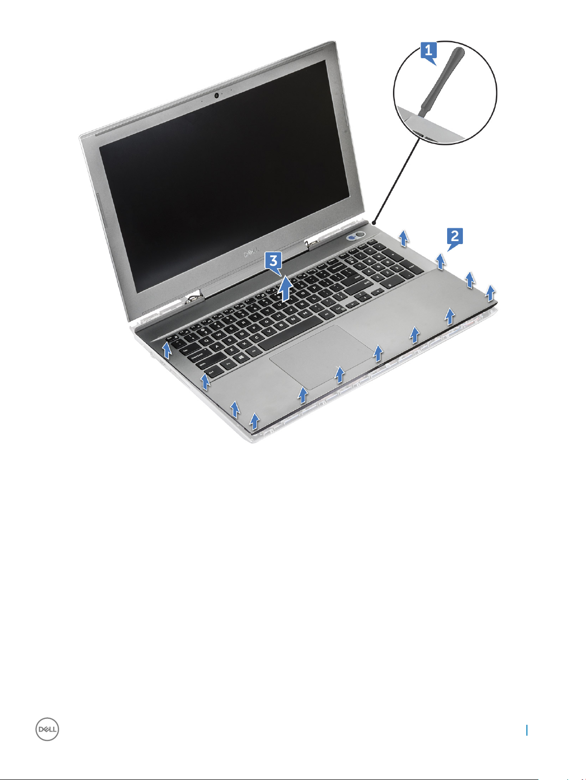
9 To remove the back cover:
a Using a plastic scribe, pry the edges of the plamrest [1, 2].
b Lift the plamrest away from the back cover [3].
24
Removing and installing components
Page 25
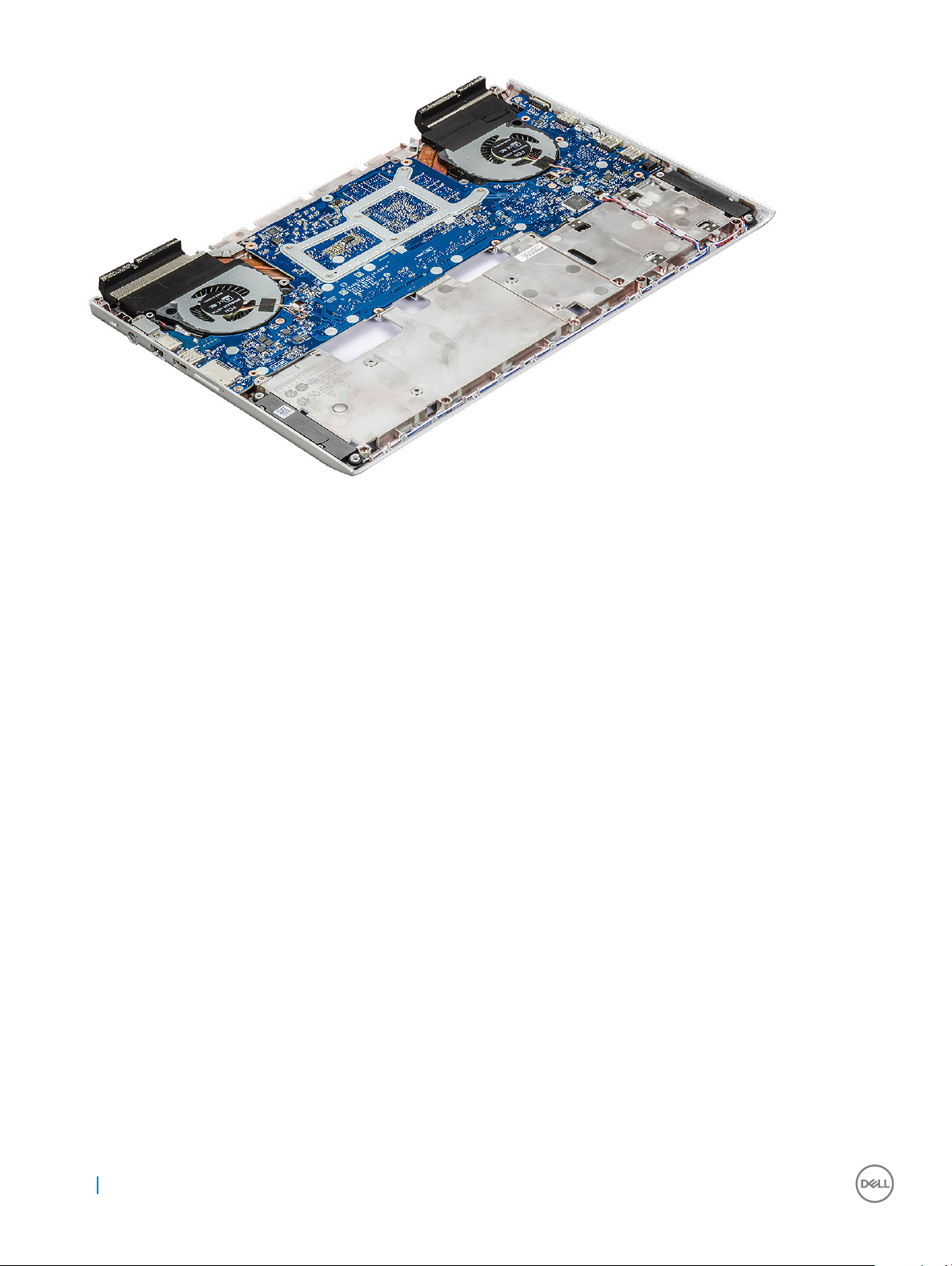
10 The component you are left with is the back cover.
Removing and installing components
25
Page 26
Installing the back cover
1 Press the edges of the back cover until it clicks into place.
2 Close the display assembly and turn over the system.
3 Replace the M2L3(4) and M2.5xL6 (19) screws to the back cover to the computer.
4 Connect the power, LED and Keyboard backlight cable, touchpad, keyboard cable and ax the white adhesive tape to the connector
to the computer.
5 Route the eDP cable through the routing and connect the cable to the computer.
6 Place the metal bracket and replace the M2x3 screw to secure the eDP to the computer.
7 Route the camera and WLAN cables through the routing channel and connect the cable to the computer.
8 Install the:
a battery
b base cover
9 Follow the procedure in After working inside your computer.
Speaker
Removing the speaker
1 Follow the procedure in Before working inside your computer.
2 Remove the:
a base cover
b battery
c SSD card
d memory module
e rear cover
f back cover
26
Removing and installing components
Page 27
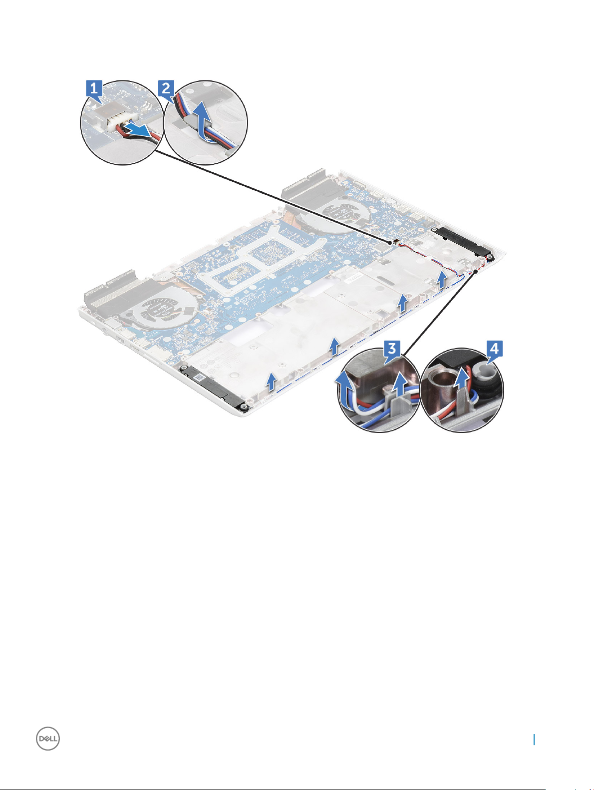
3 To remove the speaker:
a Disconnect the speaker cable [1].
b Unroute the cable from routing channel [2, 3, 4].
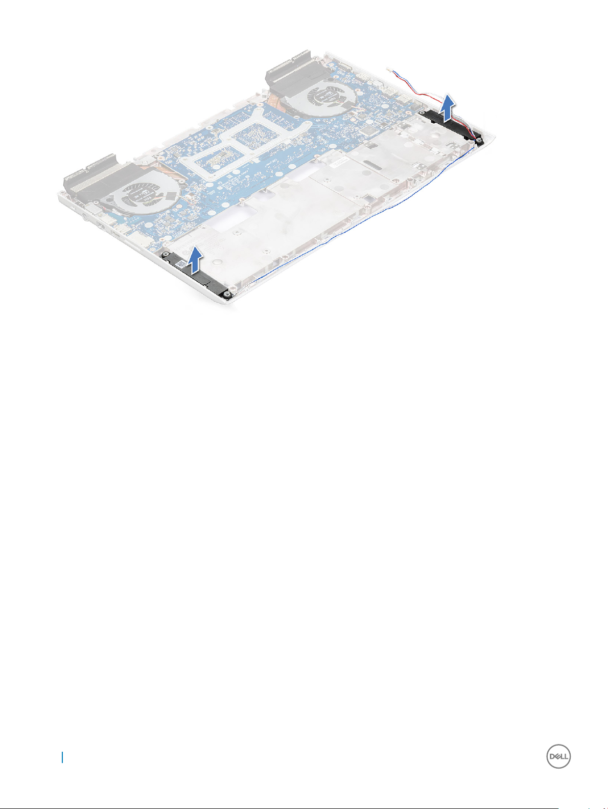
4 Lift the speakers, along with the speaker cable, and remove it away from the back cover.
Removing and installing components
27
Page 28
Installing the speaker
1 Align the speakers along the slots on the computer.
2 Route the speaker cable through the routing tabs on the computer.
3 Connect the speaker cable to the system board.
4 Install the:
a back cover
b rear cover
c memory module
d SSD card
e battery
f base cover
5 Follow the procedure in After working inside your computer.
System board
Removing the system board
1 Follow the procedure in Before working inside your computer.
2 Remove the:
a base cover
b battery
c SSD card
d memory module
e rear cover
f back cover
3 Disconnect the following cable:
28
Removing and installing components
Page 29

a Disconnect the coin cell battery cable from the connector [1].
b Disconnect the hard drive cable from the connector [2].
4 Remove the following metal tab:
a Remove the M2.5xL5(2) screws that secure the metal tab on the system board [1].
b Lift the metal tab that secures the power port on the system board [2].
c Remove the M2.5xL5(2) screws that secure the metal tab on the system board [3].
d Lift the metal tab that secures the Thunderbolt port on the system board [4].
e Disconnect the speaker cable from the system board [5].
Removing and installing components
29
Page 30

5 Remove the M2x3L(4) screws that secure the system fan to the system board.
30
Removing and installing components
Page 31

6 To remove the system board:
a Remove the 2.5x5L(3) screws that secure the system board to the computer [1].
b Lift and remove the system board from the computer [2].
Installing the system board
1 Align the system board into its original position on the computer.
2 Replace the 2.5x5L (3) screws to secure the system board to the computer.
3 Replace the M2x3L(4) screws that secure the system fan to the system board.
4 Connect the speaker cable to the system board.
5 Place the metal on the Thunderbolt port and replace M2.5xL5(2) screws that secures on the system board.
6 Place the metal on the power port and replace M2.5xL5(2) screw that secures on the system board.
7 Connect the coin cell battery and hard drive cable to the connector on the system board.
8 Connect the speaker cable to the system board.
9 Install the:
a back cover
b rear cover
c memory module
d SSD card
e battery
f base cover
10 Follow the procedure in After working inside your computer.
Removing and installing components
31
Page 32

Power connector port
Removing the power connector port
1 Follow the procedure in Before working inside your computer.
2 Remove the:
a base cover
b battery
c SSD card
d memory module
e rear cover
f back cover
g system board
3 To remove power connector port:
a Unroute the power connector port from the routing channel [1].
b Remove the power connector port from the computer [2].
32 Removing and installing components
Page 33

Installing the power connector port
1 Place the power connector port on the computer.
2 Route the power connector port cable through the routing channels on the computer.
3 Install the:
a system board
b back cover
c rear cover
d memory module
e SSD card
f battery
g base cover
4 Follow the procedure in After working inside your computer.
Heat sink
Removing the heat sink assembly
1 Follow the procedure in Before working inside your computer.
2 Remove the:
a base cover
b battery
c SSD card
d memory module
e rear cover
f back cover
3 Disconnect the heat sink assembly cables from the system board [1, 2].
Removing and installing components
33
Page 34

4 To remove the heat sink assembly:
a Turn over the system board and remove the M2x3L(6) screws that secure the heat sink assembly to the system board [1].
NOTE: Loosen the screws based on the numbering on the heat sink.
b Lift the heat sink assembly from the system board [2].
5 The component you are left with is the heat sink assembly.
Installing the heat sink assembly
1 Replace the heat sink assembly on the system board.
2 Replace the M2x3L(6) screws to secure the heat-sink assembly to the system board.
34
Removing and installing components
Page 35

NOTE: Tighten the screws based on the order mentioned in the removal procedure.
3 Turn over the system board.
4 Connect the heat sink assembly cable to the system board.
5 Install the:
a back cover
b rear cover
c memory module
d SSD card
e battery
f base cover
6 Follow the procedure in After working inside your computer.
Touchpad
Removing the touchpad
1 Follow the procedure in Before working inside your computer.
2 Remove the:
a base cover
b battery
c SSD card
d memory module
e rear cover
f back cover
3 Remove the M2x2L (4) screws from the touchpad board and slide from the display assembly [1, 2].
4 Lift the touchpad from the display assembly.
Removing and installing components
35
Page 36

Installing the touchpad
1 Place the touchpad into the slots on the display assembly.
2 Replace the M2x2L (4) screws that secure touchpad on the display assembly.
3 Install the:
a back cover
b rear cover
c memory module
d SSD card
e battery
f base cover
4 Follow the procedure in After working inside your computer.
LED board
Removing the LED board
1 Follow the procedure in Before working inside your computer.
2 Remove the:
a base cover
b battery
c SSD card
d memory module
e rear cover
f back cover
3 To remove LED board:
a Lift the latch and disconnect the LED board cable [1].
b Remove M2x3L screw that secures the LED board cable to the display assembly [2].
36
Removing and installing components
Page 37

c Slide and lift the LED board from the display assembly [3].
Installing the LED board
1 Place the LED board into the slots on the display assembly.
2 Replace the M2x3L screw that secures LED board on the display assembly.
3 Connect the LED board cable to the display assembly.
4 Install the:
a back cover
b rear cover
c memory module
d SSD card
e battery
f base cover
5 Follow the procedure in After working inside your computer.
Power button board
Removing the power button board
1 Follow the procedure in Before working inside your computer.
2 Remove the:
a base cover
b battery
Removing and installing components
37
Page 38

c SSD card
d memory module
e rear cover
f back cover
3 To release the power button board:
a Lift the latch and disconnect the power button board cable [1].
b Peel of the power button board cable from the adhesive [2].
4 To remove power button board:
a Remove the M2x3L (2) screws that secure the power button board [1].
b Lift and remove the power button board [2].
38
Removing and installing components
Page 39

Installing the power button board
1 Place the power button board into the slots on the display assembly.
2 Replace the M2x3L (2) screw that secures power button board on the display assembly.
3 Connect the power button board cable to the display assembly.
4 Install the:
a back cover
b rear cover
c memory module
d SSD card
e battery
f base cover
5 Follow the procedure in After working inside your computer.
Fingerprint reader
Removing the ngerprint reader
1 Follow the procedure in Before working inside your computer.
2 Remove the:
Removing and installing components
39
Page 40

a base cover
b battery
c SSD card
d memory module
e rear cover
f back cover
3 To release the ngerprint reader:
a By using a plastic scribe lift the ngerprint reader board [1].
b Remove the M2x2 screws that secure the ngerprint reader to the palm rest [2].
c Lift the ngerprint reader away from the palm rest [3].
Installing the ngerprint reader
1 Place the ngerprint reader into the slots on the palm rest.
2 Replace the M2x2 (2) screws that secure ngerprint reader on the display assembly.
3 Install the:
a back cover
b rear cover
c memory module
d SSD card
e battery
f base cover
4 Follow the procedure in After working inside your computer.
40
Removing and installing components
Page 41

Keyboard
Removing the keyboard
1 Follow the procedure in Before working inside your computer.
2 Remove the:
a base cover
b battery
c SSD card
d memory module
e rear cover
f back cover
g display hinge
3 Disconnect the following cables:
a power board cable
b LED board cable
c keyboard backlight cable
d touchpad cable
e keyboard cable
4 Remove the M1.6x2.2L (30) screws and lift the keyboard [1, 2].
Removing and installing components
41
Page 42

5 Remove the keyboard from the palm rest.
Installing the keyboard
1 Place the keyboard into the slots on the palm rest.
2 Replace the M1.6x2.2L (30) screws that secure keyboard on the palm rest.
3 Connect the following cable to the display assembly.
a power board cable
42
Removing and installing components
Page 43

b LED board cable
c keyboard backlight cable
d touchpad cable
e keyboard cable
4 Install the:
a display hinge
b back cover
c rear cover
d memory module
e SSD card
f battery
g base cover
5 Follow the procedure in After working inside your computer.
Display assembly
Removing the display assembly
1 Follow the procedure in Before working inside your computer.
2 Remove the:
a base cover
b battery
c SSD card
d memory module
e rear cover
f back cover
3 To remove hinge bracket:
a Remove M2.5x5L(2) screws that secure the hinge bracket to the display assembly [1].
b Lift the hinge bracket from the display assembly [2].
Removing and installing components
43
Page 44

4 Slide and lift the display assembly.
5 The component you are left with is the display assembly.
44
Removing and installing components
Page 45

Installing the display assembly
1 Place the display assembly on the computer.
2 Place the hinge bracket on the display assembly.
3 Replace the M2.5x5L(2) screws that secure the hinge bracket to the display assembly.
4 Install the:
a back cover
b rear cover
c memory module
d SSD card
e battery
f base cover
5 Follow the procedure in After working inside your computer.
Palm rest
Removing the palm rest assembly
1 Follow the procedure in Before working inside your computer.
2 Remove the:
a base cover
b battery
c coin cell battery
d SSD card
e memory module
f hard drive
g WLAN card
h rear cover
i back cover
j touchpad
k LED board
l power button board
m ngerprint reader
n keyboard
o display assembly
p display hinge
NOTE
: After the removal of all the components the component that you are left with is the palm rest
Removing and installing components 45
Page 46

3 Install the following components on the new palm rest.
a display hinge
b display assembly
c keyboard
d ngerprint reader
e power button board
f LED board
g touchpad
h back cover
i rear cover
j WLAN card
k hard drive
l memory module
m SSD card
n coin cell battery
o battery
p base cover
4 Follow the procedure in After working inside your computer
Display bezel
Removing the display bezel
1 Follow the procedure in Before working inside your computer.
2 Remove the:
a base cover
b battery
c SSD card
d memory module
e rear cover
f back cover
46
Removing and installing components
Page 47

g display assembly
3 Using a plastic scribe, pry the edges to release the display bezel from the display assembly [1, 2].
4 Remove the display bezel from display assembly.
Removing and installing components
47
Page 48

Installing the display bezel
1 Place the display bezel on the display assembly.
2 Starting from the top corner, press on the display bezel and work around the entire bezel until it clicks on to the display assembly.
3 Install the:
a display assembly
b back cover
c rear cover
d memory module
e SSD card
f battery
g base cover
4 Follow the procedure in After working inside your computer.
Camera
Removing the camera
1 Follow the procedure in Before working inside your computer.
2 Remove the:
a base cover
b battery
c SSD card
d memory module
e rear cover
f back cover
g display assembly
h display bezel
3 To remove the camera:
a Slide the camera from the display [1].
b Disconnect the camera cable from the connector [2].
c Lift the camera away from the display [3].
48
Removing and installing components
Page 49

Installing the camera
1 Place the camera on the display assembly.
2 Connect the camera cable to the connector on the display assembly.
3 Install the:
a display bezel
b display assembly
c back cover
d rear cover
e memory module
f SSD card
g battery
h base cover
4 Follow the procedure in After working inside your computer.
Display hinges
Removing the display hinge
1 Follow the procedure in Before working inside your computer.
2 Remove the:
Removing and installing components
49
Page 50

a base cover
b battery
c SSD card
d memory module
e rear cover
f back cover
g display assembly
h display bezel
3 To remove the display hinge:
a Remove the M2.5x2.5L (8) screws that secure the display hinge to the display assembly [1].
b Lift the display hinge away from the display assembly [2].
Installing the display hinge
1 Place the display hinge cover on the display assembly.
2 Tighten the M2.5x2.5L (8) screws to secure the display hinge cover to the display assembly.
3 Install the:
a display bezel
b display assembly
c back cover
d rear cover
e memory module
f SSD card
50
Removing and installing components
Page 51

g battery
h base cover
4 Follow the procedure in After working inside your computer.
Display panel
Removing the display panel
1 Follow the procedure in Before working inside your computer.
2 Remove the:
a base cover
b battery
c SSD card
d memory module
e rear cover
f back cover
g display assembly
h display bezel
i display hinge
3 Remove the M2x2.5L (4) screws that secure the display panel to the display assembly [1] and lift to turn over the display panel to
access the eDP cable [2].
4 To remove display panel:
a Remove the adhesive tape [1].
b Lift the latch and disconnect the display cable from the connector on the display panel [2].
c Lift the display panel [3].
Removing and installing components
51
Page 52

Installing the display panel
1 Connect the eDP cable to the connector.
2 Ax the adhesive tape to secure the eDP cable.
3 Replace the display panel to align with the screw holders on the display assembly.
4 Tighten the M2x2.5L (4) screws to secure the display panel to the display assembly.
5 Install the:
a display bezel
b display assembly
c back cover
d rear cover
e memory module
f SSD card
g battery
h base cover
6 Follow the procedure in After working inside your computer.
eDP cable
Removing the eDP cable
1 Follow the procedure in Before working inside your computer.
2 Remove the:
a base cover
b battery
c SSD card
d memory module
e rear cover
52
Removing and installing components
Page 53

f back cover
g display assembly
h display bezel
i display hinge
j display panel
3 Unroute the eDP cable from the routing channel to remove from the display.
Installing the eDP cable
1 Place the eDP cable on the display panel.
2 Route the eDP cable through the routing channel.
3 Install the:
a display panel
b display bezel
c display assembly
d back cover
e rear cover
f memory module
g SSD card
h battery
i base cover
4 Follow the procedure in After working inside your computer.
Removing and installing components
53
Page 54

Display back cover assembly
Removing the display back cover assembly
1 Follow the procedure in Before working inside your computer.
2 Remove the:
a base cover
b battery
c SSD card
d memory module
e rear cover
f back cover
g display assembly
h display bezel
i display hinge
j display panel
k camera
l eDP cable
3 The display back cover assembly is the remaining component, after removing all the components.
Installing the display back cover assembly
1 The display back cover assembly is the remaining component, after removing all the components.
2 Install the:
a eDP cable
b camera
c display panel
d display bezel
e display assembly
54
Removing and installing components
Page 55

f back cover
g rear cover
h memory module
i SSD card
j battery
k base cover
3 Follow the procedure in After working inside your computer.
Removing and installing components 55
Page 56

Technology and components
This chapter details the technology and components available in the system.
Topics:
• AC Adapters
• HM175
• DDR4
• USB features
• USB Type C
• HDMI 1.4
• Intel HD Graphics 630
• NVIDIA GeForce GTX 1050 Graphics
• NVIDIA GeForce GTX 1050Ti Graphics
• NVIDIA GeForce GTX 1060 Graphics
AC Adapters
3
This laptop is shipped with following AC adapter:
• 130 W 3-Pin
• 180 W 3-Pin
• When you disconnect the AC adapter cable from the computer, grasp the connector, not the cable itself, and then pull rmly but gently
to avoid damaging the cable.
• The AC adapter works with electrical outlets worldwide. However, power connectors and power strips vary among countries. Using an
incompatible cable or improperly connecting the cable to the power strip or electrical outlet may cause re or equipment damage.
How to check the status of AC Adapter in BIOS?
1 Restart / Power on your computer.
2 At the rst text on the screen or when the Dell logo appears, tap <F2> until the message Entering Setup appears.
3 Under General > Battery Information, you will see AC Adapter listed.
HM175
Mobile Chipset
The mobile Intel® HM175 Express Chipset is part of the mobile Intel® 7 Series Chipset family.
• It brings in fast I/O capabilities with great exibility and a host of other power packed features to compliment the performance benets
of mobile 7th Gen Intel® Core™ processor.
56 Technology and components
Page 57

• The 100 series PCH oers a host of incremental features compared to the 9 series PCH such as additional USB 3.0 ports and faster
data transfer between the processor and the PCH with DMI 3.0.
• The latest Intel® Rapid Storage Technology 15 with Intel® HM175 chipset supports NVMe* PCIe* x4 Solid State Drives.
Features and Benets
Table 2. HM175 features and benets
Features and Benets
Support for Mobile 6th & 7th Gen Intel Core
Processors
Intel® Rapid Recover Technology
Intel® Identity Protection Technology Help protect your one-time-password (OTP) credentials.
Intel® High Denition Audio Integrated audio support enables premium digital surround sound and delivers advanced
Universal Serial Bus 3.1 Gen 1 Integrated USB 3.1 Gen 1 support, provides a design data rate of up to 5 gigabits per
USB Port Disable Enables individual USB ports to be enabled or disabled as needed. This feature provides
PCI Express 3.0 interface
SATA Port Disable Enables individual SATA ports to be enabled or disabled as needed. This feature provides
Support for 6th & 7th Gen Intel® Core™ processors with great power and performance.
Provides excellent levels of performance, responsiveness, and expandability. Take
advantage of the enhanced performance and low power consumption available with
Intel® RST with one or more SATA or PCIe* storage drives. With additional SATA drives,
Intel® RST provides quick access to digital photo, video, and data les with RAID 0, 5,
and 10, and excellent data protection against a storage disk drive failure with RAID 1, 5,
and 10. Dynamic Storage Accelerator unleashes the maximum performance of Solid State
Drives (SSD) when multitasking.
features such as multiple audio streams and jack re-tasking
second (Gbps) with up to 8 USB 3.1 Gen 1 ports.
added protection of data by preventing malicious removal or insertion of data through
USB ports.
Oers up to 8 GT/s for fast access to peripheral devices and networking with up to 16
PCI Express 3.0 ports, congurable as x1, x2, and x4 depending on motherboard designs.
added protection of data by helping to prevent malicious removal or insertion of data
through SATA ports. Especially targeted for eSATA ports.
USB 2.0 rate matching hub Hi-speed USB 2.0 support with a design data rate of up to 480 megabits per second
(Mbps) with up to 14 USB 2.0 ports.
Serial ATA (SATA) 6 Gb/s and 3 Gb/s High-speed storage interface supporting up to 6 Gb/s transfer rate for improved data
access. Provides up to six SATA ports with up to two ports supporting 6 Gb/s transfer
rates.
eSATA SATA interface designed for use with external SATA devices. Provides a link for 3 Gb/s
data speeds to eliminate bottlenecks found with current external storage solutions.
Intel® integrated 10/100/1000 MAC
NOTE: Not all features mentioned here for the HM175 Express chipset may be available for Dell units, please refer to particular
system specication for detail.
Support for the Intel® I219LM and Intel® I219V Gigabit Network Connection.
DDR4
DDR4 (double data rate fourth generation) memory is a higher-speed successor to the DDR2 and DDR3 technologies and allows up to 512
GB in capacity, compared to the DDR3's maximum of 128 GB per DIMM. DDR4 synchronous dynamic random-access memory is keyed
dierently from both SDRAM and DDR to prevent the user from installing the wrong type of memory into the system.
Technology and components
57
Page 58

DDR4 needs 20 percent less or just 1.2 volts, compared to DDR3 which requires 1.5 volts of electrical power to operate. DDR4 also supports
a new, deep power-down mode that allows the host device to go into standby without needing to refresh its memory. Deep power-down
mode is expected to reduce standby power consumption by 40 to 50 percent.
DDR4 Details
There are subtle dierences between DDR3 and DDR4 memory modules, as listed below.
Key notch dierence
The key notch on a DDR4 module is in a dierent location from the key notch on a DDR3 module. Both notches are on the insertion edge
but the notch location on the DDR4 is slightly dierent, to prevent the module from being installed into an incompatible board or platform.
Figure 1. Notch dierence
Increased thickness
DDR4 modules are slightly thicker than DDR3, to accommodate more signal layers.
Figure 2. Thickness dierence
Curved edge
DDR4 modules feature a curved edge to help with insertion and alleviate stress on the PCB during memory installation.
Figure 3. Curved edge
58
Technology and components
Page 59

Memory Errors
Memory errors on the system display the new ON-FLASH-FLASH or ON-FLASH-ON failure code. If all memory fails, the LCD does not
turn on. Troubleshoot for possible memory failure by trying known good memory modules in the memory connectors on the bottom of the
system or under the keyboard, as in some portable systems.
USB features
Universal Serial Bus, or USB, was introduced in 1996. It dramatically simplied the connection between host computers and peripheral
devices like mice, keyboards, external drivers, and printers.
Let's take a quick look on the USB evolution referencing to the table below.
Table 3. USB evolution
Type Data Transfer Rate Category Introduction Year
USB 3.0/USB 3.1 Gen 2 5 Gbps Super Speed 2010
USB 2.0 480 Mbps High Speed 2000
USB 3.0/USB 3.1 Gen 1 (SuperSpeed USB)
For years, the USB 2.0 has been rmly entrenched as the de facto interface standard in the PC world with about 6 billion devices sold, and
yet the need for more speed grows by ever faster computing hardware and ever greater bandwidth demands. The USB 3.0/USB 3.1 Gen 1
nally has the answer to the consumers' demands with a theoretically 10 times faster than its predecessor. In a nutshell, USB 3.1 Gen 1
features are as follows:
• Higher transfer rates (up to 5 Gbps)
• Increased maximum bus power and increased device current draw to better accommodate power-hungry devices
• New power management features
• Full-duplex data transfers and support for new transfer types
• Backward USB 2.0 compatibility
• New connectors and cable
The topics below cover some of the most commonly asked questions regarding USB 3.0/USB 3.1 Gen 1.
Speed
Currently, there are 3 speed modes dened by the latest USB 3.0/USB 3.1 Gen 1 specication. They are Super-Speed, Hi-Speed and FullSpeed. The new SuperSpeed mode has a transfer rate of 4.8Gbps. While the specication retains Hi-Speed, and Full-Speed USB mode,
commonly known as USB 2.0 and 1.1 respectively, the slower modes still operate at 480Mbps and 12Mbps respectively and are kept to
maintain backward compatibility.
USB 3.0/USB 3.1 Gen 1 achieves the much higher performance by the technical changes below:
Technology and components
59
Page 60

• An additional physical bus that is added in parallel with the existing USB 2.0 bus (refer to the picture below).
• USB 2.0 previously had four wires (power, ground, and a pair for dierential data); USB 3.0/USB 3.1 Gen 1 adds four more for two pairs
of dierential signals (receive and transmit) for a combined total of eight connections in the connectors and cabling.
• USB 3.0/USB 3.1 Gen 1 utilizes the bidirectional data interface, rather than USB 2.0's half-duplex arrangement. This gives a 10-fold
increase in theoretical bandwidth.
With today's ever increasing demands placed on data transfers with high-denition video content, terabyte storage devices, high megapixel
count digital cameras etc., USB 2.0 may not be fast enough. Furthermore, no USB 2.0 connection could ever come close to the 480Mbps
theoretical maximum throughput, making data transfer at around 320Mbps (40MB/s) — the actual real-world maximum. Similarly, USB
3.0/USB 3.1 Gen 1 connections will never achieve 4.8Gbps. We will likely see a real-world maximum rate of 400MB/s with overheads. At this
speed, USB 3.0/USB 3.1 Gen 1 is a 10x improvement over USB 2.0.
Applications
USB 3.0/USB 3.1 Gen 1 opens up the laneways and provides more headroom for devices to deliver a better overall experience. Where USB
video was barely tolerable previously (both from a maximum resolution, latency, and video compression perspective), it's easy to imagine
that with 5-10 times the bandwidth available, USB video solutions should work that much better. Single-link DVI requires almost 2Gbps
throughput. Where 480Mbps was limiting, 5Gbps is more than promising. With its promised 4.8Gbps speed, the standard will nd its way
into some products that previously weren't USB territory, like external RAID storage systems.
Listed below are some of the available SuperSpeed USB 3.0/USB 3.1 Gen 1 products:
• External Desktop USB 3.0/USB 3.1 Gen 1 Hard Drives
• Portable USB 3.0/USB 3.1 Gen 1 Hard Drives
• USB 3.0/USB 3.1 Gen 1 Drive Docks & Adapters
• USB 3.0/USB 3.1 Gen 1 Flash Drives & Readers
• USB 3.0/USB 3.1 Gen 1 Solid-state Drives
• USB 3.0/USB 3.1 Gen 1 RAIDs
• Optical Media Drives
• Multimedia Devices
• Networking
• USB 3.0/USB 3.1 Gen 1 Adapter Cards & Hubs
Compatibility
The good news is that USB 3.0/USB 3.1 Gen 1 has been carefully planned from the start to peacefully co-exist with USB 2.0. First of all,
while USB 3.0/USB 3.1 Gen 1 species new physical connections and thus new cables to take advantage of the higher speed capability of
60
Technology and components
Page 61

the new protocol, the connector itself remains the same rectangular shape with the four USB 2.0 contacts in the exact same location as
before. Five new connections to carry receive and transmitted data independently are present on USB 3.0/USB 3.1 Gen 1 cables and only
come into contact when connected to a proper SuperSpeed USB connection.
Windows 8/10 will be bringing native support for USB 3.1 Gen 1 controllers. This is in contrast to previous versions of Windows, which
continue to require separate drivers for USB 3.0/USB 3.1 Gen 1 controllers.
Microsoft announced that Windows 7 would have USB 3.1 Gen 1 support, perhaps not on its immediate release, but in a subsequent Service
Pack or update. It is not out of the question to think that following a successful release of USB 3.0/USB 3.1 Gen 1 support in Windows 7,
SuperSpeed support would trickle down to Vista. Microsoft has conrmed this by stating that most of their partners share the opinion that
Vista should also support USB 3.0/USB 3.1 Gen 1.
Super-Speed support for Windows XP is unknown at this point. Given that XP is a seven-year-old operating system, the likelihood of this
happening is remote.
USB Type C
USB Type-C is a new, tiny physical connector. The connector itself can support various exciting new USB standard like USB 3.1 and USB
power delivery (USB PD).
Alternate Mode
USB Type-C is a new connector standard that's very small. It's about a third the size of an old USB Type-A plug. This is a single connector
standard that every device should be able to use. USB Type-C ports can support a variety of dierent protocols using “alternate modes,”
which allows you to have adapters that can output HDMI, VGA, DisplayPort, or other types of connections from that single USB port
USB Power Delivery
The USB PD specication is also closely intertwined with USB Type-C. Currently, smartphones, tablets, and other mobile devices often use
a USB connection to charge. A USB 2.0 connection provides up to 2.5 watts of power — that'll charge your phone, but that's about it. A
laptop might require up to 60 watts, for example. The USB Power Delivery specication ups this power delivery to 100 watts. It's bidirectional, so a device can either send or receive power. And this power can be transferred at the same time the device is transmitting
data across the connection.
This could spell the end of all those proprietary laptop charging cables, with everything charging via a standard USB connection. You could
charge your laptop from one of those portable battery packs you charge your smartphones and other portable devices from today. You
could plug your laptop into an external display connected to a power cable, and that external display would charge your laptop as you used
it as an external display — all via the one little USB Type-C connection. To use this, the device and the cable have to support USB Power
Delivery. Just having a USB Type-C connection doesn't necessarily mean they do.
USB Type C and USB 3.1
USB 3.1 is a new USB standard. USB 3's theoretical bandwidth is 5 Gbps, while USB 3.1's is 10 Gbps. That's double the bandwidth, as fast
as a rst-generation Thunderbolt connector. USB Type-C isn't the same thing as USB 3.1. USB Type-C is just a connector shape, and the
underlying technology could just be USB 2 or USB 3.0. In fact, Nokia's N1 Android tablet uses a USB Type-C connector, but underneath it's
all USB 2.0 — not even USB 3.0. However, these technologies are closely related.
Technology and components
61
Page 62

HDMI 1.4
This topic explains the HDMI 1.4 and its features along with the advantages.
HDMI (High-Denition Multimedia Interface) is an industry-supported, uncompressed, all-digital audio/video interface. HDMI provides an
interface between any compatible digital audio/video source, such as a DVD player, or A/V receiver and a compatible digital audio and/or
video monitor, such as a digital TV (DTV). The intended applications for HDMI TVs, and DVD players. The primary advantage is cable
reduction and content protection provisions. HDMI supports standard, enhanced, or high-denition video, plus multichannel digital audio on
a single cable.
NOTE: The HDMI 1.4 will provide 5.1 channel audio support.
HDMI 1.4 Features
• HDMI Ethernet Channel - Adds high-speed networking to an HDMI link, allowing users to take full advantage of their IP-enabled
devices without a separate Ethernet cable
• Audio Return Channel - Allows an HDMI-connected TV with a built-in tuner to send audio data "upstream" to a surround audio system,
eliminating the need for a separate audio cable
• 3D - Denes input/output protocols for major 3D video formats, paving the way for true 3D gaming and 3D home theater applications
• Content Type - Real-time signaling of content types between display and source devices, enabling a TV to optimize picture settings
based on content type
• Additional Color Spaces - Adds support for additional color models used in digital photography and computer graphics
• 4 K Support - Enables video resolutions far beyond 1080p, supporting next-generation displays that will rival the Digital Cinema systems
used in many commercial movie theaters
• HDMI Micro Connector - A new, smaller connector for phones and other portable devices, supporting video resolutions up to 1080p
• Automotive Connection System - New cables and connectors for automotive video systems, designed to meet the unique demands of
the motoring environment while delivering true HD quality
Advantages of HDMI
• Quality HDMI transfers uncompressed digital audio and video for the highest, crispest image quality.
• Low -cost HDMI provides the quality and functionality of a digital interface while also supporting uncompressed video formats in a
simple, cost-eective manner
• Audio HDMI supports multiple audio formats from standard stereo to multichannel surround sound
• HDMI combines video and multichannel audio into a single cable, eliminating the cost, complexity, and confusion of multiple cables
currently used in A/V systems
• HDMI supports communication between the video source (such as a DVD player) and the DTV, enabling new functionality
Intel HD Graphics 630
The Intel HD Graphics 630 (GT2) is an integrated graphics unit, which can be found in various desktop and notebook processors of the
Kaby lake generation. All the Intel's 7th generation Core i7, i5, i3, andHigh-performance Mobile Processors use the Intel HD 630 as their
integrated GPU..
It is manufactured using the 14nm+ technology with minor architectural improvements over the previous generation. The base frequency is
300MHz while the max frequency is 1,150 MHz. However, in the case of some Processors, the base and max frequency is slightly dierent.
It will have the same memory type as your RAM as it is an integrated GPU. Its max Video Memory (VRAM) can be changed from the BIOS
settings.
62
Technology and components
Page 63

Features
• Support for up to three independent displays via HDMI 1.4, DisplayPort (DP) 1.2, an Embedded DisplayPort (eDP) 1.4 interfaces.
• Quick Sync Video
• Clear Video
• Clear Video HD
Power Consumption
The HD Graphics 630 can be found in several notebook and desktop processors of dierent TDP classes (35 — 91 W).
Key Specications
The following table contains the key specications of the Intel HD Graphics 630:
Table 4. Key Specications
Specication Intel HD Graphics 630
HD Graphics Series HD Graphics 630
Codename Kaby-Lake-H-GT2
Architecture Intel Gen 9.5 (Kaby lake)
Pipelines 24 — unied
Core Speed * 300 — 1150 (Boost) MHz
* The specied clock rates are only guidelines for the manufacturer and can be altered by them.
Memory Bus Width 64/128 bit
Shared Memory Yes
Technology 14 nm
Features QuickSync
DirectX DirectX 12 (FL 12_1)
NVIDIA GeForce GTX 1050 Graphics
The Nvidia GTX 1050 is a mainstream GPU based on the Pascal architecture and was announced in January 2017. Contrary to the faster
models, the GTX 1050 uses the GP107 chip.
Features
The GP107 chip is manufactured in a 14 nm FinFET process at Samsung and oers a number of new features, including support for
DisplayPort 1.4 (ready), HDMI 2.0b, HDR, Simultaneous Multi-Projection (SMP) as well as improved H.265 video de- and encoding
(PlayReady 3.0).
Technology and components
63
Page 64

Power Consumption
The NVIDIA GeForce GTX 1050 Graphics can be found in several notebook and desktop processors of dierent TDP classes (40 — 50 W).
Key Specications
The following table contains the key specications of the NVIDIA GeForce GTX 1050:
Table 5. Key Specications
Specication NVIDIA GeForce GTX 1050
HD Graphics Series NVIDIA GeForce GTX 1050
Codename N17P-G0
Architecture Pascal
Pipelines 640 - unied
Core Speed * 1354 - 1493 (Boost) MHz
Memory Bus Width 7000 MHz
Shared Memory No
Technology 14 nm
Features Multi-Projection, G-SYNC, Vulkan, Multi Monitor
DirectX DirectX 12_1
NVIDIA GeForce GTX 1050Ti Graphics
The Nvidia GTX 1050 Tiis a mainstream GPU based on the Pascal architecture and was announced in January 2017. Contrary to the faster
models, the GTX 1050 Ti uses the GP107 chip.
Features
The GP107 chip is manufactured in a 14 nm FinFET process at Samsung and oers a number of new features, including support for
DisplayPort 1.4 (ready), HDMI 2.0b, HDR, Simultaneous Multi-Projection (SMP) as well as improved H.265 video de- and encoding
(PlayReady 3.0).
Power Consumption
The NVIDIA GeForce GTX 1050 Ti Graphics can be found in several notebook and desktop processors of dierent TDP classes (70 W).
Key Specications
The following table contains the key specications of the NVIDIA GeForce GTX 1050 Ti:
64
Technology and components
Page 65

Table 6. Key Specications
Specication NVIDIA GeForce GTX 1050 Ti
HD Graphics Series NVIDIA GeForce GTX 1050 Ti
Codename N17P-G1
Architecture Pascal
Pipelines 768 - unied
Core Speed * 1493 - 1620 (Boost) MHz
Memory Bus Width 7000 MHz
Shared Memory No
Technology 14 nm
Features Multi-Projection, G-SYNC, Vulkan, Multi Monitor
DirectX DirectX 12_1
NVIDIA GeForce GTX 1060 Graphics
The mobile Nvidia GeForce GTX 1060 is a graphics card for high end laptops. It is based on the Pascal architecture and manufactured in 16
nm FinFET at TSMC. The GPU is using the smaller GP106 chip. Compared to the desktop version of the GTX 1060, the laptop version
oers the same amount of shader but slightly lower clock rates.
Features
The GP106 chip is produced in 16nm FinFET at TSMC and oers a range of new features, like DisplayPort 1.4 (ready), HDMI 2.0b, HDR,
Simultaneous Multi-Projection (SMP) and improved H.265 video de- and encoding (PlayReady 3.0).
Power Consumption
NVIDIA GeForce GTX 1060 Graphics can be found in several notebook and desktop processors of dierent TDP classes (80 W).
Key Specications
The following table contains the key specications of the NVIDIA GeForce GTX 1060:
Table 7. Key
Specication NVIDIA GeForce GTX 1060
HD Graphics Series NVIDIA GeForce GTX 1060
Codename N17P-G1
Architecture Pascal
Specications
Pipelines 1280 - unied
Core Speed * 1506 - 1708 (Boost) MHz
Memory Bus Width 8000 MHz
Technology and components 65
Page 66

Specication NVIDIA GeForce GTX 1060
Shared Memory No
Technology 16 nm
Features Multi-Projection, G-SYNC, Vulkan, Multi Monitor
DirectX DirectX 12_1
66 Technology and components
Page 67

System setup
System setup enables you to manage your tabletdesktopnotebook hardware and specify BIOS level options. From the System setup, you
can:
• Change the NVRAM settings after you add or remove hardware
• View the system hardware conguration
• Enable or disable integrated devices
• Set performance and power management thresholds
• Manage your computer security
Topics:
• Boot menu
• Navigation keys
• System setup options
• Updating the BIOS in Windows
• System and setup password
4
Boot menu
Press <F12> when the Dell logo appears to initiate a one-time boot menu with a list of the valid boot devices for the system. Diagnostics
and BIOS Setup options are also included in this menu. The devices listed on the boot menu depend on the bootable devices in the system.
This menu is useful when you are attempting to boot to a particular device or to bring up the diagnostics for the system. Using the boot
menu does not make any changes to the boot order stored in the BIOS.
The options are:
• UEFI Boot:
• Windows Boot Manager
•
• Other Options:
• BIOS Setup
• BIOS Flash Update
• Diagnostics
• Change Boot Mode Settings
Navigation keys
: For most of the System Setup options, changes that you make are recorded but do not take eect until you restart the
NOTE
system.
Keys Navigation
Up arrow Moves to the previous eld.
Down arrow Moves to the next eld.
System setup 67
Page 68

Keys Navigation
Enter Selects a value in the selected eld (if applicable) or follow the link in the eld.
Spacebar Expands or collapses a drop‐down list, if applicable.
Tab Moves to the next focus area.
NOTE: For the standard graphics browser only.
Esc Moves to the previous page until you view the main screen. Pressing Esc in the main screen displays a message
that prompts you to save any unsaved changes and restarts the system.
System setup options
NOTE: Depending on the tabletnotebook and its installed devices, the items listed in this section may or may not appear.
General screen options
This section lists the primary hardware features of your computer.
Option Description
System Information This section lists the primary hardware features of your computer.
• System Information: Displays BIOS Version, Service Tag, Asset Tag, Ownership Tag, Manufacture Date,
Ownership Date, and the Express Service Code.
• Memory Information: Displays Memory Installed, Memory Available, Memory Speed, Memory Channels Mode,
Memory Technology, DIMM A Size, DIMM B Size
• Processor Information: Displays Processor Type, Core Count, Processor ID, Current Clock Speed, Minimum
Clock Speed, Maximum Clock Speed, Processor L2 Cache, Processor L3 Cache, HT Capable, and 64-Bit
Technology.
• Device Information: Displays M.2 SATA, Primary Hard Drive, M.2 PCIe SSD-0, LOM MAC Address, dGPU Vide
Controller, Video BIOS Version, Video Memory, Panel Type, Native Resolution, Audio Controller, Wi-Fi Device,
Bluetooth Device.
Battery Information Displays the battery status and the type of AC adapter connected to the computer.
Boot Sequence Allows you to change the order in which the computer attempts to nd an operating system.
• Windows Boot Manager
• Boot list options:
• Legacy
• UEFI (selected by default)
Advanced Boot
Options
Date/Time Allows you to change the date and time.
This option allows you the legacy option ROMs to load. By default, the Enable Legacy Option ROMs is enabled.
• Enable Attempt Legacy Boot
68 System setup
Page 69

System Conguration screen options
Option Description
Integrated NIC Allows you to congure the integrated network controller. The options are:
• Disabled
• Enabled
• Enabled w/PXE: This option is enabled by default.
SATA Operation Allows you to congure the internal SATA hard-drive controller. The options are:
• Disabled
• AHCI
• RAID On: This option is enabled by default.
Drives Allows you to congure the SATA drives on board. All drives are enabled by default. The options are:
• SATA-0
• SATA-1
• M.2 PCI-e SSD-0
SMART Reporting This eld controls whether hard drive errors for integrated drives are reported during system startup. This
technology is part of the SMART (Self Monitoring Analysis and Reporting Technology) specication. This option is
disabled by default.
USB Conguration
Thunderbolt Adapter
Conguration
• Enable SMART Reporting
This is an optional feature.
This eld congures the integrated USB controller. If Boot Support is enabled, the system is allowed to boot any
type of USB Mass Storage Devices (HDD, memory key, oppy).
If USB port is enabled, device attached to this port is enabled and available for OS.
If USB port is disabled, the OS cannot see any device attached to this port.
The options are:
• Enable Boot support (by default enable)
• Enable external USB ports
NOTE: USB keyboard and mouse always work in the BIOS setup irrespective of these settings.
The options for Thunderbolt Adapter Conguration are:
• Enable Thunderbolt Technology Support (selected by default)
• Enable Thunderbolt Adapter Boot Support
• Enable Thunderbolt Adapter Pre-boot Modules
• Security Level — No Security
• Security Level — User Authorization (selected by default)
• Security Level — Secure Connect
• Security Level — Display Port Only
System setup 69
Page 70

Option Description
USB PowerShare This eld congures the USB PowerShare feature behavior. This option allows you to charge external devices using
the stored system battery power through the USB PowerShare port (disabled by default).
Audio This eld enables or disables the integrated audio controller. By default, the Enable Audio option is selected. The
options are:
• Enable Microphone (by default enable)
• Enable Internal Speaker (by default enable)
Keyboard
Illumination
Keyboard Backlight
with AC
Miscellaneous
Devices
This eld lets you choose the operating mode of the keyboard illumination feature. The keyboard brightness level
can be set from 0% to 100%. The options are:
• Disabled
• Dim
• Bright (selected by default)
The Keyboard Backlight with AC option does not aect the main keyboard illumination feature. Keyboard
Illumination will continue to support the various illumination levels. This eld has an eect when the backlight is
enabled (selected by default).
Allows you to enable or disable the following devices:
• Enable Camera (selected by default)
• Enable HardDrive Free Fall Protection (selected by default)
Video screen options
Option
LCD Brightness Allows you to set the display brightness depending upon the power source. On Battery(50% is default) and On AC
Description
(100 % default).
Security screen options
Option
Admin Password Allows you to set, change, or delete the administrator (admin) password.
System Password Allows you to set, change or delete the system password.
M.2 SATA SSD
Password
70 System setup
Description
NOTE: You must set the admin password before you set the system or hard drive password. Deleting
the admin password automatically deletes the system password and the hard drive password.
NOTE: Successful password changes take eect immediately.
Default setting: Not set
NOTE: Successful password changes take eect immediately.
Default setting: Not set
Allows you to set, change or delete the M.2 SATA SSD.
Page 71

Option Description
NOTE: Successful password changes take eect immediately.
Default setting: Not set
Strong Password Allows you to enforce the option to always set strong passwords.
Default Setting: Enable Strong Password is not selected.
NOTE: If Strong Password is enabled, Admin and System passwords must contain at least one
uppercase character, one lowercase character and be at least 8 characters long.
Password
Conguration
Password Bypass Allows you to enable or disable the permission to bypass the System and the Internal HDD password, when they
Password Change Allows you to enable the disable permission to the System and Hard Drive passwords when the admin password is
Non-Admin Setup
Changes
UEFI Capsule
Firmware Updates
Allows you to specify the minimum and max password lengths of Administrator and System passwords.
• minimum -4(by default, if you want to change you can increase the number)
• maximum -32 ( you can decrease the number)
are set. The options are:
• Disabled
• Reboot bypass
Default setting: Disabled
set.
Default setting: Allow Non-Admin Password Changes is selected.
Allows you to determine whether changes to the setup options are allowed when an Administrator Password is set.
If disabled the setup options are locked by the admin password.
• allow wireless switch changes
Allows you to enable or disable. This option controls whether this system allows BIOS updated via UEFI capsule
update packages. The options are:
• Enable UEFI Capsule Firmware—enabled by default
TPM 2.0 Security Allows you to enable the Trusted Platform Module (TPM) during POST. The options are:
• TPM On (selected by default)
• Clear (option is disabled)
• PPI Bypass for Enabled Commands (selected by default)
• PPI Bypass for Disabled Commands
• Disabled
• Enabled
• Attestation enable (selected by default)
• Key storage enable (selected by default)
• SHA-256 (selected by default)
NOTE: To upgrade or downgrade TPM1.2/2.0, download the TPM wrapper tool (software).
Computrace Allows you to activate or disable the optional Computrace software The options are:
• Deactivate
System setup 71
Page 72

Option Description
• Disable
• Activate (selected by default)
NOTE: The Activate and Disable options will permanently activate or disable the feature and no further
changes will be allowed
CPU XD Support Allows you to enable the Execute Disable mode of the processor.
Enable CPU XD Support (default)
OROM Keyboard
Access
Admin Setup
Lockout
Master password
lockout
Allows you to set an option to enter the Option ROM Conguration screens using hotkeys during boot. The options
are:
• Enable
• One Time Enable
• Disable
Default setting: Enable
Allows you to prevent users from entering Setup when an Administrator password is set.
Default Setting: Disabled
This option is not selected by default
Secure Boot screen options
Option
Secure Boot Enable This option enables or disables the Secure Boot feature.
Description
• Disabled
• Enabled
Expert Key
Management
72 System setup
Default setting: Enabled.
Allows you to manipulate the security key databases only if the system is in Custom Mode. The Enable Custom
Mode option is disabled by default. The options are:
• PK—enabled by default
• KEK
• db
• dbx
If you enable the Custom Mode, the relevant options for PK, KEK, db, and dbx appear. The options are:
• Save to File—Saves the key to a user-selected le
• Replace from File—Replaces the current key with a key from a user-selected le
• Append from File—Adds a key to the current database from a user-selected le
• Delete—Deletes the selected key
• Reset All Keys—Resets to default setting
• Delete All Keys—Deletes all the keys
Page 73

Option Description
NOTE: If you disable the Custom Mode, all the changes made are erased and the keys restore to default
settings.
Intel Software Guard Extensions screen options
Option Description
Intel SGX Enable This eld species you to provide a secured environment for running code/storing sensitive information in the
context of the main OS. The options are:
• Disabled
• Enabled
• Software controlled (default)
Enclave Memory
Size
This option sets SGX Enclave Reserve Memory Size. The options are:
• 32 MB
• 64 MB
• 128 MB (default)
Performance screen options
Option
Multi Core Support This eld species whether the process has one or all cores enabled. The performance of some applications
Intel SpeedStep Allows you to enable or disable the Intel SpeedStep feature.
Description
improves with the additional cores.
• All (selected by default)
• 1
• 2
• 3
• Enable Intel SpeedStep
Default setting: The option is enabled.
C-States Control Allows you to enable or disable the additional processor sleep states.
• C states
Default setting: The option is enabled.
Intel TurboBoost Allows you to enable or disable the Intel TurboBoost mode of the processor.
• Enable Intel TurboBoost
Default setting: The option is enabled.
System setup 73
Page 74

Power Management screen options
Option Description
AC Behavior Allows you to enable or disable the computer from turning on automatically when an AC adapter is connected.
Default setting: Wake on AC is not selected.
Enable Intel Speed
Shift Technology
Auto On Time Allows you to set the time at which the computer must turn on automatically. The options are:
USB Wake Support Allows you to enable USB devices to wake the system from Standby.
Wake on LAN Allows you to enable or disable the feature that powers on the computer from the O state when triggered by a
Allows you to enable or disable the Intel Speed Shift Technology.
Default setting: Enabled
• Disabled
• Every Day
• Weekdays
• Select Days
Default setting: Disabled
NOTE: This feature is only functional when the AC power adapter is connected. If the AC power
adapter is removed during Standby, the system setup removes power from all the USB ports to
conserve battery power.
• Enable USB Wake Support
LAN signal.
• Disabled (Enabled)
• LAN Only
Advanced Battery
Charge
Conguration
Primary Battery
Charge
Conguration
Type-C connector
power
74 System setup
This option enables you to maximize the battery health. By enabling this option, your system uses the standard
charging algorithm and other techniques, during the non-work hours to improve the battery health.
Allows you to select the charging mode for the battery. The options are:
• Adaptive (default)
• Standard — Fully charges your battery at a standard rate.
• ExpressCharge — The battery charges over a shorter period of time using Dell’s fast charging technology. This
option is enabled by default.
• Primarily AC use
• Custom
If Custom Charge is selected, you can also congure Custom Charge Start and Custom Charge Stop.
NOTE: All charging mode may not be available for all the batteries. To enable this option, disable the
Advanced Battery Charge Conguration option.
• 7.5 Watts(selected by default)
• 15 Watts
Page 75

POST Behavior screen options
Option Description
Adapter Warnings Allows you to enable or disable the system setup (BIOS) warning messages when you use certain power adapters.
Default setting: Enable Adapter Warnings
Numlock Enable Allows you to enable the Numlock option when the computer boots.
Enable Network. This option is enabled by default.
Fn Lock Options
Fastboot Allows you to speed up the boot process by bypassing some of the compatibility steps. The options are:
Extended BIOS
POST Time
Full Screen Logo This option will display full screen logo if your image match screen resolution
Allows you to let hot key combinations Fn + Esc toggle the primary behavior of F1–F12, between their standard
and secondary functions. If you disable this option, you cannot toggle dynamically the primary behavior of these
keys. The available options are:
• Fn Lock. This option is selected by default.
• Lock Mode Disable/Standard
• Lock Mode Enable/Secondary
• Minimal
• Thorough (default)
• Auto
Allows you to create an additional preboot delay. The options are:
• 0 seconds. This option is enabled by default.
• 5 seconds
• 10 seconds
• Enable Full Screen Logo
Sign of Life
Indication
This option will allows system to indicate during POST that the power button press has been acknowledge in a
manner the user can either hear or feel.
Enable Sign of Life keyboard Backlight Indication (enabled by default
Virtualization support screen options
Option
Virtualization Allows you to enable or disable the Intel Virtualization Technology.
VT for Direct I/O Enables or disables the Virtual Machine Monitor (VMM) from utilizing the additional hardware capabilities provided
Description
Enable Intel Virtualization Technology (default).
by Intel® Virtualization technology for direct I/O.
Enable VT for Direct I/O - enabled by default.
System setup 75
Page 76

Wireless screen options
Option Description
Wireless Switch Allows to set the wireless devices that can be controlled by the wireless switch. The options are:
• WLAN
• Bluetooth
All the options are enabled by default.
Wireless Device
Enable
Allows you to enable or disable the internal wireless devices.
• WLAN
• Bluetooth
All the options are enabled by default.
Maintenance screen options
Option
Service Tag Displays the Service Tag of your computer.
Asset Tag Allows you to create a system asset tag if an asset tag is not already set. This option is not set by default.
BIOS Downgrade This controls ashing of the system rmware to previous revisions.
Data Wipe This eld allows users to erase the data securely from all internal storage devices. The following is list of devices
Description
aected:
• Internal SATA HDD/SSD
• Internal M.2 SATA SDD
• Internal M.2 PCIe SSD
• Internal eMMC
BIOS Recovery This eld allows you to recover from certain corrupted BIOS conditions from a recover le on the user primary hard
drive or an external USB key.
• BIOS Recovery from Hard Drive (enabled by default)
• BIOS Auto-Recovery
• Always perform integrity check (disabled by default)
System Log screen options
Option
BIOS Events Allows you to view and clear the System Setup (BIOS) POST events.
Thermal Events Allows you to view and clear the System Setup (Thermal) events.
Power Events Allows you to view and clear the System Setup (Power) events.
76 System setup
Description
Page 77

SupportAssist System Resolution
Option Description
Auto OS Recovery
Threshold
SupportAssist OS
Recovery
Allows you to control the automatic boot ow for SupportAssist System. Options are:
• O
• 1
• 2 (Enabled by default)
• 3
Allows you to recover the SupportAssist OS Recovery (Disabled by default)
Updating the BIOS in Windows
It is recommended to update your BIOS (System Setup), on replacing the system board or if an update is available. For laptops, ensure that
your computer battery is fully charged and connected to a power outlet
NOTE: If BitLocker is enabled, it must be suspended prior to updating the system BIOS, and then re-enabled after the BIOS
update is completed.
1 Restart the computer.
2 Go to Dell.com/support.
• Enter the Service Tag or Express Service Code and click Submit.
• Click Detect Product and follow the instructions on screen,
3 If you are unable to detect or nd the Service Tag, click the Choose from all products.
4 Choose the Products category from the list.
NOTE
: Choose the appropriate category to reach the product page
5 Select your computer model and the Product Support page of your computer appears.
6 Click Get drivers and click Drivers and Downloads.
The Drivers and Downloads section opens.
7 Click Find it myself.
8 Click BIOS to view the BIOS versions.
9 Identify the latest BIOS le and click Download.
10 Select your preferred download method in the Please select your download method below window, click Download File.
The File Download window appears.
11 Click Save to save the le on your computer.
12 Click Run to install the updated BIOS settings on your computer.
Follow the instructions on the screen.
NOTE
: It is recommended not to update the BIOS version for more than 3 revisions. For example: If you want to update the BIOS
from 1.0 to 7.0, then install version 4.0 rst and then install version 7.0.
System and setup password
You can create a system password and a setup password to secure your computer.
Password type
System password Password that you must enter to log on to your system.
Description
System setup 77
Page 78

Password type Description
Setup password Password that you must enter to access and make changes to the BIOS settings of your computer.
CAUTION: The password features provide a basic level of security for the data on your computer.
CAUTION: Anyone can access the data stored on your computer if it is not locked and left unattended.
NOTE: Your computer is shipped with the system and setup password feature is disabled.
Assigning a system password and setup password
You can assign a new System Password only when the status is in Not Set.
To enter the system setup, press F2 immediately after a power-on or re-boot.
1 In the System BIOS or System Setup screen, select Security and press Enter.
The Security screen is displayed.
2 Select System Password and create a password in the Enter the new password eld.
Use the following guidelines to assign the system password:
• A password can have up to 32 characters.
• The password can contain the numbers 0 through 9.
• Only lower case letters are valid, upper case letters are not allowed.
• Only the following special characters are allowed: space, (”), (+), (,), (-), (.), (/), (;), ([), (\), (]), (`).
3 Type the system password that you entered earlier in the Conrm new password eld and click OK.
4 Press Esc and a message prompts you to save the changes.
5 Press Y to save the changes.
The computer reboots.
Deleting or changing an existing system and or setup password
Ensure that the Password Status is Unlocked (in the System Setup) before attempting to delete or change the existing System and/or
Setup password. You cannot delete or change an existing System or Setup password, if the Password Status is Locked.
To enter the System Setup, press F2 immediately after a power-on or reboot.
1 In the System BIOS or System Setup screen, select System Security and press Enter.
The System Security screen is displayed.
2 In the System Security screen, verify that Password Status is Unlocked.
3 Select System Password, alter or delete the existing system password and press Enter or Tab.
4 Select Setup Password, alter or delete the existing setup password and press Enter or Tab.
NOTE
: If you change the System and/or Setup password, re-enter the new password when promoted. If you delete the
System and/or Setup password, conrm the deletion when promoted.
5 Press Esc and a message prompts you to save the changes.
6 Press Y to save the changes and exit from System Setup.
The computer reboots.
78
System setup
Page 79

System specications
NOTE: Oerings may vary by region. The following specications are only those required by law to ship with your computer. For
more information about the conguration of your computer, go to Help and Support in your Windows operating system and
select the option to view information about your computer.
Topics:
• System information
• Processor
• Memory
• Video
• Audio
• Communication
• Ports and connectors
• Display
• Keyboard
• Touchpad
• Camera
• Storage
• Battery
• AC adpter
• Physical dimension
• Environmental
5
System information
Feature
System Chipset Intel HM175
Specication
Processor
Feature
Processor type Intel Kaby Lake -H
L1 cache Up to 32 KB cache depending on processor type
L2 cache Up to 256 KB cache depending on processor type
L3 cache Up to 8 MB cache depending on processor type
Intel Smart cache
with Last Level
Cache
Specication
Up to 8 MB cache depending on processor type
System specications 79
Page 80

Memory
Feature Specication
Type DDR4 SDRAM
Speed 2400 MHz
Connectors 4
Capacity 4 GB, 8GB, 16 GB
Minimum Memory 4 GB ( 1 x 4GB)
Maximum memory 32 GB
Video
Feature Specication
Type MXM type-A add-in card
Data bus PCIE x16, Gen3
Video controller and
memory:
• Intel HD Graphics 630
• NVIDIA GeForce GTX 1050 Graphics with 2GB/4GB GDDR5 vRAM
• NVIDIA GeForce GTX 1050Ti Graphics with 4GB GDDR5 vRAM
• NVIDIA GeForce GTX 1060 Graphics with 6GB GDDR5 vRAM
Audio
Features
Integrated dual-channel High-Denition audio
Specication
Communication
Feature
Ethernet adapter network interface card capable of 10/100/1000 mb/s communication
Wireless
Specication
WLAN options:
• Qualcomm QCA9377 802.11ac Dual Band (1x1) Wireless Adapter+ Bluetooth 4.1
• Intel Wireless-AC 3165 1x1 802.11AC Wi-Fi + BT 4.2 LE Wireless Card
• DW1820 2x2 ac 802.11ac+BT4.1
Ports and connectors
Feature
Audio Universal audio jack connector
Network Adapter one RJ45 connector
80 System specications
Specication
Page 81

USB C connector
with Thunderbolt
one (optional)
USB 3.1 with Gen 1
(with PowerShare)
Video HDMI 2.0
Memory card reader SD 4.0
three
Display
Features Specication
Type FHD (1920 x 1080)
Size 15.6 inches
Dimensions:
Height 193.59 mm (7.62 inches)
Width 344.16 mm (13.54 inches)
Diagonal 396.24 mm (15.60 inches)
Active area (X/Y) FHD (1920 x 1080)
Maximum resolution FHD (1920 x 1080)
Maximum
Brightness
15.6" FHD Anti-Glare LED-backlit —220 nits
Operating angle 0° (closed) to 135°
Refresh rate 60 Hz
Minimum viewing
angles:
Horizontal FHD (80/80/80/80)
Vertical FHD (80/80/80/80)
Keyboard
Features
Number of keys
Layout QWERTY/AZERTY/Kanji
Specication
• United States: 82 keys
• United Kingdom: 83 keys
• Japan: 105 keys
Touchpad
Features
X/Y position
resolution
Specication
• X: 41.27+-4.13 counts/mm
• Y: 38.75+-3.88 counts/mm
System specications 81
Page 82

• 1048/984 cpi
Size Sensor-active area:
• Width: 99.5 mm (3.92 inches)
• Height: 53 mm (2.09 inches)
Multi-Touch Congurable single nger and multi-nger gestures
Camera
Features Specication
Type CMOS Sensor
Still Resolution 1280 x 720 Pixels (Maximum)
Video Resolution 1280 x 720 Pixels (Maximum)
Diagonal 74 degrees
Storage
Features Specication
Storage:
• 1 TB 5400 RPM HDD 2.5" (7 mm)
• 512 GB M.2 2230 PCIe NVMe SSD
• 500 GB 7200 RPM HDD 2.5" (7 mm)
• 256 GB M.2 2280 SATA SSD
• 256 GB M.2 2230 PCIe NVMe SSD
• 128 GB M.2 2280 SATA SSD
Battery
Features
Wattage 56 Whr (4 Cell) Prismatic with ExpressCharge
Type Li-polymer
Length 233.06 mm (9.170 inches)
Height 5.9 mm (0.232 inches)
Width 90.73 mm (3.572 inches)
Weight 250.00 g
Voltage 15.2 VDC
Specication
Life span
Temperature range:
Operating
82 System specications
• 300 discharge/charge cycles
• 1000 discharge/charge cycles (LCL)
• Charge: 0° C to 50° C (32° F to 158° F)
Page 83

• Discharge: 0° C to 70° C (32° F to 122° F)
Non-Operating -20° C to 65° C (4° F to 149° F)
Coin-cell battery 3 V CR2032 lithium ion cell
AC adpter
Features Specication
Wattage 180 W
Input voltage 100 VAC to 240 VAC
Input current
(maximum)
Input frequency 50 Hz to 60 Hz
Output current 9.23 A (continuous)
Rated output
voltage
Height 30.4 mm (1.2 inches)
Width 76.2 mm (3.0 inches)
Depth 154.9 mm (6.1 inches)
Weight 0.57 kg (1.25 lb)
Temperature range:
Operating 0°C to 40°C (32°F to 104°F)
Non-Operating –40°C to 70°C (–40°F to 158°F)
3.5 A
19.50 VDC
Physical dimension
Feature
Weight (pounds/
kilograms)
Specication
5.86 lb/2.66 kg
Dimensions
Height (inches/mm)
Front 23.95 mm (0.94 inch)
Rear 24.95 mm (0.98 inch)
Width (inches/mm) 389.0 mm (15.31 inch)
Depth (inches/mm) 270.0 mm (10.62 inches)
Environmental
Feature
Temperature range:
Specication
System specications 83
Page 84

Operating 10° C to 35° C (50° F to 95° F)
Storage -40° C to 65° C (-40° F to 149° F)
Relative humidity
(maximum):
Storage 20% to 80% (non-condensing)
Maximum vibration:
Operating 5 to 350 Hz at 0.0002 G²/Hz
Storage 5 to 500 Hz at 0.001 to 0.01 G²/Hz
Maximum shock:
Operating 40 G +/- 5% with pulse duration of 2 msec +/-10% (equivalent to 51 cm/sec [20 in/sec])
Storage 105 G +/- 5% with pulse duration of 2 msec +/-10% (equivalent to 127 cm/sec [50 in/sec])
Maximum Altitude:
Operating –15.2 to 3048 m (–50 to 10,000 ft)
Storage –15.2 to 10,668 m (–50 to 35,000 ft)
84 System specications
Page 85

This chapter details the supported operating systems along with instructions on how to install the drivers.
Topics:
• Operating system congurations
• Device drivers
Operating system congurations
This topic lists the operating system supported by
Table 8. Operating systems
6
Software
Windows 10
Others
• Microsoft Windows 10 Home 64 bit
• Microsoft Windows10 Professional 64 bit
• Microsoft Windows 10 National Academic 64-bit (Bid Desk)
• Ubuntu 16.04 LTS 64-bit
Device drivers
This section provides information about Windows 10 drivers. Drivers can be downloaded from the Dell Support website. Most of the device
drivers are pre-installed during the Windows installation process. For best results, Dell recommends installing the chipset driver utility rst,
followed by the rest of the devices' drivers/software packages in any sequence.
Table 9. Device drivers
Categories Driver Name
Chipset Drivers Intel Chipset
Intel Management Engine Interface
Intel Serial I/O
Intel Dynamic Platform and Thermal Framework Drivers
Intel Software Guard Extensions
Intel HID Event Filter
Display Drivers Intel HD Graphics
Audio Driver Realtek audio driver
Network Drivers Bluetooth Drivers
Realtek Ethernet
Realtek Card Reader
Security Fingerprint Reader
Software 85
Page 86

Intel chipset drivers
Verify if the Intel chipset drivers are already installed in the laptop.
Table 10. Intel chipset drivers
Before installation After installation
Intel management engine interface
Verify if the Intel management engine interface drivers are already installed in the laptop.
86
Software
Page 87

Table 11. Intel management engine interface
Before installation After installation
Intel Serial Input Output
Verify if the Intel Serial I/O driver is already installed in the system, by referring to the illustration below.
Software
87
Page 88

Table 12. Intel Serial Input Output
Before installation After installation
Intel dynamic platform and thermal framework drivers
Verify if the Intel dynamic platform and thermal framework drivers are already installed in the laptop.
Table 13. Intel dynamic platform and thermal framework drivers
Before installation After installation
Intel software guard extensions
There is no visible change in the Device Manager after the Software Guard Extensions driver is installed.
Before you can install this driver, Intel Software Guard Extensions must be enabled in BIOS.
88
Software
Page 89

Intel HID event lter
Verify if the Intel HID event lter driver are already installed in the laptop.
Table 14. Intel HID event lter
Before installation After installation
Intel HD Graphics
Verify if the Intel HD Graphics driver is already installed in the system, by referring to the illustration below.
Table 15. Intel HD Graphics
Before installation After installation
Realtek audio driver
Verify if the Realtek audio driver are already installed in the laptop.
Table 16. Realtek audio driver
Before installation After installation
|
Bluetooth drivers
This platform supports a variety of Bluetooth drivers. The following is an example.
Software
89
Page 90

Table 17. Bluetooth drivers
Before installation After installation
Intel Ethernet controller drivers
Verify if the Intel ethernet controller drivers are already installed in the laptop. There is no visible change before and after installation
Table 18. Intel Ethernet controller drivers
Before installation After installation
RealTek card reader drivers
Verify if the RealTek card reader drivers are already installed in the laptop.
Table 19. RealTek card reader drivers
Before installation After installation
Fingerprint Reader
Verify if the Fingerprint Reader driver is already installed in the system, by referring to the illustration below.
Table 20. Fingerprint Readers
Before installation After installation
90 Software
Page 91

7
Troubleshooting
Enhanced Pre-Boot System Assessment — ePSA diagnostics
The ePSA diagnostics (also known as system diagnostics) performs a complete check of your hardware. The ePSA is embedded with the
BIOS and is launched by the BIOS internally. The embedded system diagnostics provides a set of options for particular devices or device
groups allowing you to:
• Run tests automatically or in an interactive mode
• Repeat tests
• Display or save test results
• Run thorough tests to introduce additional test options to provide extra information about the failed device(s)
• View status messages that inform you if tests are completed successfully
• View error messages that inform you of problems encountered during testing
CAUTION
results or error messages.
NOTE: Some tests for specic devices require user interaction. Always ensure that you are present at the computer terminal
when the diagnostic tests are performed.
: Use the system diagnostics to test only your computer. Using this program with other computers may cause invalid
Running the ePSA diagnostics
1 Power-on the computer.
2 As the computer boots, press the F12 key as the Dell logo appears.
3 On the boot menu screen, select the Diagnostics option.
4 Click the arrow key at the bottom left corner.
Diagnostics front page is displayed.
5 Press the arrow in the lower-right corner to go to the page listing.
The items detected are listed.
6 To run a diagnostic test on a specic device, press Esc and click Yes to stop the diagnostic test.
7 Select the device from the left pane and click Run Tests.
8 If there are any issues, error codes are displayed.
Note the error code and validation number and contact Dell.
Diagnostic LED
This section details the diagnostic features of the battery LED in a notebook.
Instead of beep codes errors are indicated via the bicolor Battery Charge LED. A specic blink pattern is followed by ashing a pattern of
ashes in amber, followed by white. The pattern then repeats.
: The diagnostic pattern will consist of a two digit number being represented by a rst group of LED blinks (1 through 9) in
NOTE
amber, followed by a 1.5 second pause with the LED o, and then a second group of LED blinks (1 through 9) in white. This is
then followed by a three second pause, with the LED o, before repeating over again. Each LED blink takes 0.5 seconds.
Troubleshooting 91
Page 92

The system will not shutdown when displaying the Diagnostic Error Codes. Diagnostic Error Codes will always supersede any other use of
the LED. For instance, on Notebooks, battery codes for Low Battery or Battery Failure situations will not be displayed when Diagnostic
Error Codes are being displayed:
Table 21. LED pattern
Blinking pattern Problem Description Suggested Resolution
Amber White
2 1 processor processor failure
2 2 system board, BIOS ROM system board, covers BIOS corruption or ROM error
2 3 memory no memory/no RAM detected
2 4 memory memory failure/RAM failure
2 5 memory invalid memory installed
2 6 system board; chipset system board/ chipset error
2 7 display display failure
3 1 RTC power failure coin-cell battery failure
3 2 PCI/Video PCI/Video card/chip failure
3 3 BIOS recovery 1 recovery image nor found
3 4 BIOS recovery 2 recovery image found but invalid
Battery status lights
If the computer is connected to an electrical outlet, the battery light operates as follows:
Alternately blinking
amber light and
white light
Alternately blinking
amber light with
steady white light
Constantly blinking
amber light
Light o Battery in full charge mode with AC adapter present.
White light on Battery in charge mode with AC adapter present.
An unauthenticated or unsupported non-Dell AC adapter is attached to your laptop.
Temporary battery failure with AC adapter present.
Fatal battery failure with AC adapter present.
Dell Docking Solution
Thunderbolt 3 Type-C port does not support certain docking systems features
The Vostro 15-7570 system do not support all of the Dell Docking solution features of the Dell Thunderbolt Dock TB16, Dell Dock WD15, Dell
Universal Dock D6000, as well as third-party docking solutions features.
NOTE
: The Dell Power Manager (DPM V3.0) will pop up an alert message informing you of this issue.
92 Troubleshooting
Page 93

Table 22. Dell Docking solution features not supported
Features Description
Power Delivery Allows Dell Docks (Thunderbolt Dock TB16 / Dell Dock WD15/ Dell
Universal Dock D6000) to provide power input through the Type-C
connector.
Power/ Wake on dock button
Port Disablement Allows IT managers to turn o ports in the dock for securing
Error Message and Dock Event Notications User will be notied when an insucient power adapter or cable is
Wake on dock attached
Cable FW updates Ability to receive future enhancements or xes from Dell (Dell
Cable LED Indicates dock connection status (Dell Thunderbolt Dock TB16 and
Run Time MAC address Overwrite Bypasses the docking MAC address so IT professionals can identify
Dock rmware updates Ability to receive future enhancements or xes from Dell (Dell
LAN Cable detection WLAN/WWAN is auto disabled when LAN is attached to the dock
Ability to power on laptops by using the dock button (Dell
Thunderbolt Dock TB16 and Dell Dock WD15)
condential information (Dell Thunderbolt Dock TB16 and Dell Dock
WD15)
paired with the dock and advised to use the recommended
accessory. Notications of rmware updates and port disablement.
Examples include Wake on LAN and LAN Cable detect (Dell
Thunderbolt Dock TB16 and Dell Dock WD15)
Dock will power on the system automatically (Dell Thunderbolt
Dock TB16 and Dell Dock WD15)
Thunderbolt Dock TB16 and Dell Dock WD15)
Dell Dock WD15)
the user by the notebook/Tablet MAC address and not the
common address in the docking stations (Dell Thunderbolt Dock
TB16 and Dell Dock WD15)
Thunderbolt Dock TB16 and Dell Dock WD15)
(Dell Thunderbolt Dock TB16 and Dell Dock WD15)
Third-party docking solutions features
• The Vostro 15-7570 system supports standard Thunderbolt 3 protocol/features on external graphic docks. However, performance has
not been validated in many third-party Thunderbolt 3 eGfx docks and so users may experience certain unexpected compatibility issues.
Hybrid Power
Users may observe certain behaviors when the system is heavily loaded or in certain gaming conditions, such as:
• Battery capacity does not increase even when connected to the power adapter.
• Battery charges slowly when connected to the power adapter.
The hybrid power feature in the Vostro 15–7570 systems enable the battery to output power to the system during heavy loading and in
certain gaming conditions to support overall system power demand (as long as battery capacity is above 10 %).
Battery charging will resume immediately as soon as the system exits the heavy loading condition.
Troubleshooting
93
 Loading...