

Dell Vostro 15 User Manual

Dell Vostro 15 – 3546
Owner's Manual
Regulatory Model: P45F
Regulatory Type: P45F001

Notes, Cautions, and Warnings
NOTE: A NOTE indicates important information that helps you make better use of your computer.
CAUTION: A CAUTION indicates either potential damage to hardware or loss of data and tells you
how to avoid the problem.
WARNING: A WARNING indicates a potential for property damage, personal injury, or death.
Copyright © 2014 Dell Inc. All rights reserved. This product is protected by U.S. and international copyright and
intellectual property laws. Dell™ and the Dell logo are trademarks of Dell Inc. in the United States and/or other
jurisdictions. All other marks and names mentioned herein may be trademarks of their respective companies.
2014 - 08
Rev. A00

Contents
1 Working on Your Computer................................................................................5
Connecting the Power Adapter............................................................................................................ 5
System Overview...................................................................................................................................6
Front and Back View .......................................................................................................................6
Before Working Inside Your Computer................................................................................................ 7
Recommended Tools............................................................................................................................8
Turning Off Your Computer..................................................................................................................8
After Working Inside Your Computer................................................................................................... 9
2 Removing and Installing Components...........................................................10
Removing the Battery..........................................................................................................................10
Installing the Battery............................................................................................................................ 11
Removing the Optical Drive................................................................................................................ 11
Installing the Optical Drive.................................................................................................................. 11
Removing the Access Panel................................................................................................................ 11
Installing the Access Panel..................................................................................................................12
Removing the Hard Drive....................................................................................................................12
Installing the Hard Drive......................................................................................................................13
Removing the Memory Module.......................................................................................................... 13
Installing the Memory Module............................................................................................................ 14
Removing the WLAN Card.................................................................................................................. 14
Installing the WLAN Card.................................................................................................................... 14
Removing the Keyboard......................................................................................................................15
Installing the Keyboard........................................................................................................................16
Removing the Palmrest Assembly.......................................................................................................17
Installing the Palmrest Assembly........................................................................................................ 19
Removing the Battery Connector.......................................................................................................19
Installing the Battery Connector........................................................................................................ 20
Removing the Coin-Cell Battery........................................................................................................ 20
Installing the Coin-cell battery........................................................................................................... 21
Removing the Optical Drive Connector.............................................................................................21
Installing the Optical Drive Connector...............................................................................................22
Removing the Input/Output (I/0) Board.............................................................................................22
Installing the Input/Output (I/O) Board..............................................................................................23
Removing the Speakers...................................................................................................................... 24
Installing the Speakers........................................................................................................................ 25
Removing the System Board.............................................................................................................. 25
Installing the System Board................................................................................................................ 26

Removing the Display Assembly.........................................................................................................27
Installing the Display Assembly...........................................................................................................29
Removing the Camera........................................................................................................................30
Installing the Camera...........................................................................................................................31
Removing the Heatsink....................................................................................................................... 31
Installing the Heatsink Assembly........................................................................................................ 32
Removing the Power Connector........................................................................................................32
Installing the Power Connector..........................................................................................................33
3 System Setup.......................................................................................................34
Boot Sequence....................................................................................................................................34
Navigation Keys...................................................................................................................................34
System Setup Options.........................................................................................................................35
Updating the BIOS ..............................................................................................................................39
System and Setup Password...............................................................................................................39
Assigning a System Password and Setup Password.................................................................... 40
Deleting or Changing an Existing System and/or Setup Password............................................ 40
4 Diagnostics.......................................................................................................... 41
Enhanced Pre-Boot System Assessment (ePSA) Diagnostics............................................................41
Device Status Lights............................................................................................................................ 41
Power Status Lights.............................................................................................................................42
5 Specifications...................................................................................................... 43
Specifications...................................................................................................................................... 43
6 Contacting Dell...................................................................................................48
Contacting Dell................................................................................................................................... 48
Working on Your Computer
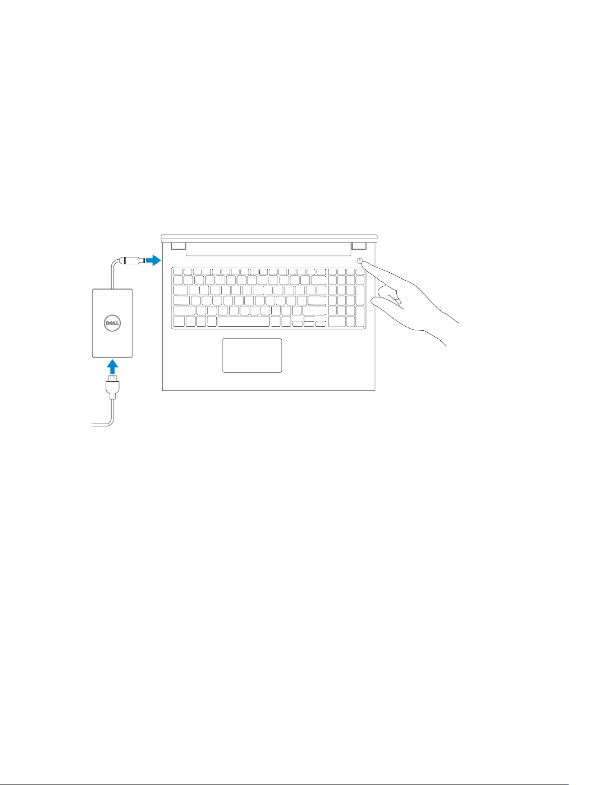
Connecting the Power Adapter
Connect the power adapter and turn on your computer.
1
5
System Overview
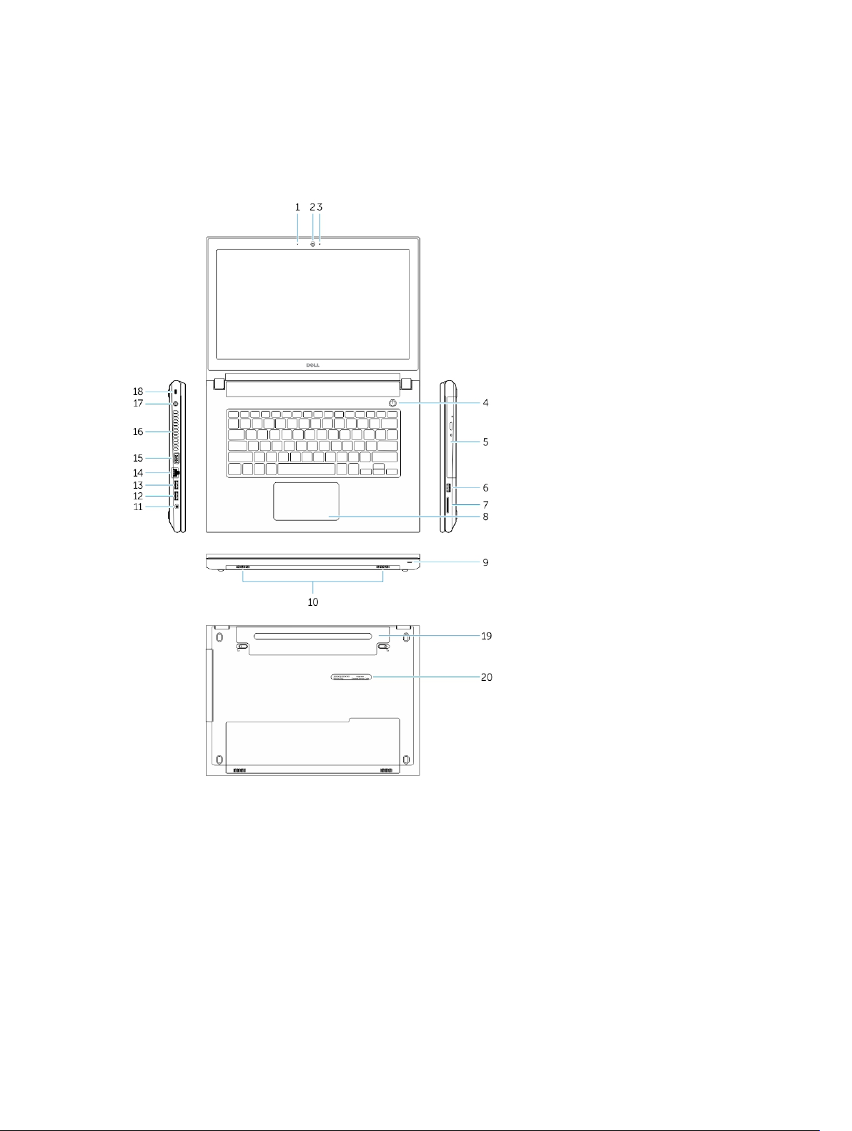
Front and Back View
1. microphone 2. camera
3. camera-status light 4. power button
5. optical drive 6. USB 2.0 connector
7. memory-card reader 8. touchpad
9. power and battery-status light 10. speakers
11. audio connector 12. USB 3.0 connector
13. USB 2.0 connector 14. network connector
6
15. VGA connector 16. air vents
17. power connector 18. security-cable slot
19. battery 20. service-tag label
Before Working Inside Your Computer
Use the following safety guidelines to help protect your computer from potential damage and to help to
ensure your personal safety. Unless otherwise noted, each procedure included in this document assumes
that the following conditions exist:
• You have read the safety information that shipped with your computer.
• A component can be replaced or--if purchased separately--installed by performing the removal
procedure in reverse order.
WARNING: Disconnect all power sources before opening the computer cover or panels. After you
finish working inside the computer, replace all covers, panels, and screws before connecting to
the power source.
WARNING: Before working inside your computer, read the safety information that shipped with
your computer. For additional safety best practices information, see the Regulatory Compliance
Homepage at
CAUTION: Many repairs may only be done by a certified service technician. You should only
perform troubleshooting and simple repairs as authorized in your product documentation, or as
directed by the online or telephone service and support team. Damage due to servicing that is
not authorized by Dell is not covered by your warranty. Read and follow the safety instructions
that came with the product.
CAUTION: To avoid electrostatic discharge, ground yourself by using a wrist grounding strap or
by periodically touching an unpainted metal surface, such as a connector on the back of the
computer.
CAUTION: Handle components and cards with care. Do not touch the components or contacts
on a card. Hold a card by its edges or by its metal mounting bracket. Hold a component such as a
processor by its edges, not by its pins.
CAUTION: When you disconnect a cable, pull on its connector or on its pull-tab, not on the cable
itself. Some cables have connectors with locking tabs; if you are disconnecting this type of cable,
press in on the locking tabs before you disconnect the cable. As you pull connectors apart, keep
them evenly aligned to avoid bending any connector pins. Also, before you connect a cable,
ensure that both connectors are correctly oriented and aligned.
NOTE: The color of your computer and certain components may appear differently than shown in
this document.
www.dell.com/regulatory_compliance
To avoid damaging your computer, perform the following steps before you begin working inside the
computer.
1. Ensure that your work surface is flat and clean to prevent the computer cover from being scratched.
2. Turn off your computer (see Turning off Your Computer).
3. If the computer is connected to a docking device (docked), undock it.
CAUTION: To disconnect a network cable, first unplug the cable from your computer and
then unplug the cable from the network device.
4. Disconnect all network cables from the computer.
7
5. Disconnect your computer and all attached devices from their electrical outlets.
6. Close the display and turn the computer upside-down on a flat work surface.
NOTE: To avoid damaging the system board, you must remove the main battery before you
service the computer.
7. Remove the main battery.
8. Turn the computer top-side up.
9. Open the display.
10. Press the power button to ground the system board.
CAUTION: To guard against electrical shock, always unplug your computer from the
electrical outlet before opening the display.
CAUTION: Before touching anything inside your computer, ground yourself by touching an
unpainted metal surface, such as the metal at the back of the computer. While you work,
periodically touch an unpainted metal surface to dissipate static electricity, which could
harm internal components.
11. Remove any installed ExpressCards or Smart Cards from the appropriate slots.
Recommended Tools
The procedures in this document may require the following tools:
• Small flat-blade screwdriver
• #0 Phillips screwdriver
• #1 Phillips screwdriver
• Small plastic scribe
Turning Off Your Computer
CAUTION: To avoid losing data, save and close all open files and exit all open programs before
you turn off your computer.
1. Shut down the operating system:
• In Windows 8.1:
– Using a touch-enabled device:
a. Swipe in from the right edge of the screen, opening the Charms menu and select
Settings.
b. Select the and then select Shut down.
– Using a mouse:
a. Point to upper-right corner of the screen and click Settings.
b. Click the and select Shut down.
• In Windows 7:
1. Click Start .
8
2. Click Shut Down.
or
1. Click Start .
2. Click the arrow in the lower-right corner of the Start menu as shown below, and then click
Shut Down .
2. Ensure that the computer and all attached devices are turned off. If your computer and attached
devices did not automatically turn off when you shut down your operating system, press and hold
the power button for about 6 seconds to turn them off.
After Working Inside Your Computer
After you complete any replacement procedure, ensure you connect any external devices, cards, and
cables before turning on your computer.
CAUTION: To avoid damage to the computer, use only the battery designed for this particular
Dell computer. Do not use batteries designed for other Dell computers.
1. Connect any external devices, such as a port replicator or media base, and replace any cards, such as
an ExpressCard.
2. Connect any telephone or network cables to your computer.
CAUTION: To connect a network cable, first plug the cable into the network device and then
plug it into the computer.
3. Replace the battery.
4. Connect your computer and all attached devices to their electrical outlets.
5. Turn on your computer.
9
Removing and Installing Components
This section provides detailed information on how to remove or install the components from your
computer.
Removing the Battery
1. Follow the procedures in Before Working Inside Your Computer.
2. Perform the following steps as shown in the illustration:
a. Slide the latches outward [1].
b. Release the battery [2].
2
3. Lift the battery to remove it from the computer.
10
Installing the Battery
1. Insert the battery into the battery slot and press to lock in place.
2. Follow the procedures in After Working Inside Your computer.
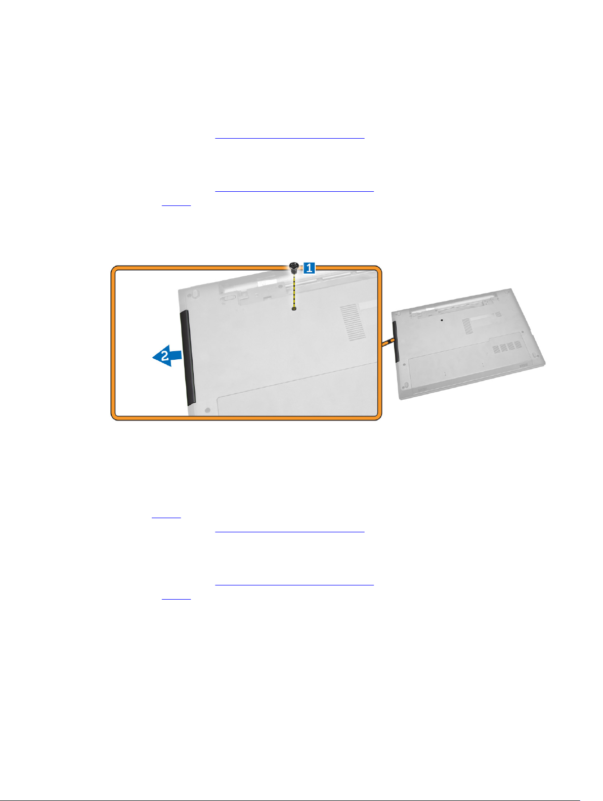
Removing the Optical Drive
1. Follow the procedures in Before Working Inside Your Computer
2. Remove the battery.
3. Perform the following steps as shown in the illustration:
a. Remove the screw that secures the optical drive [1].
b. Slide the optical drive out of the computer [2].
Installing the Optical Drive
1. Slide the optical drive into the computer.
2. Tighten the screw to secure the optical drive.
3. Install the battery.
4. Follow the procedures in After Working Inside Your computer.
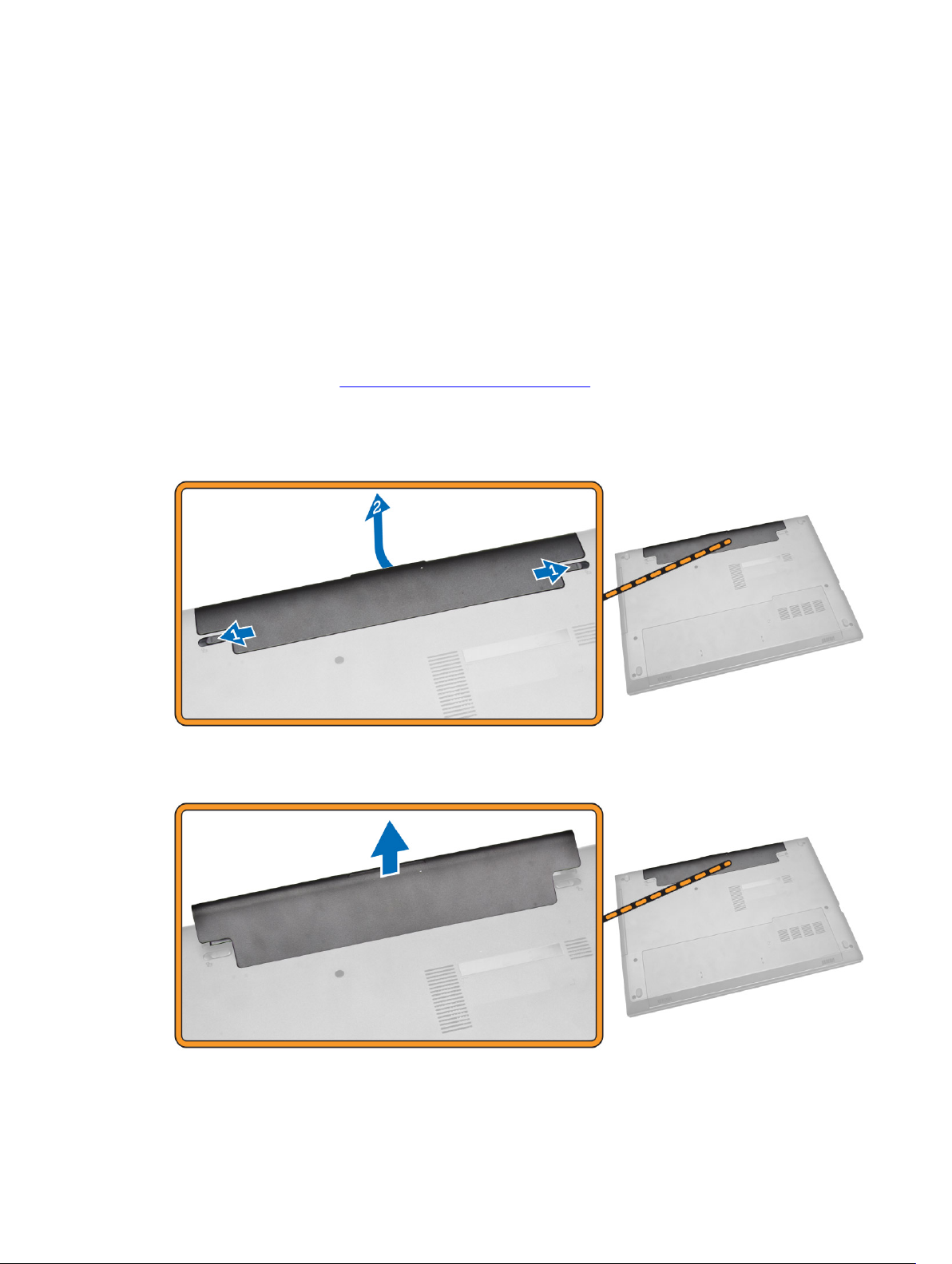
Removing the Access Panel
1. Follow the procedures in Before Working Inside Your Computer.
2. Remove the battery.
3. Perform the following steps as shown in the illustration:
a. Loosen the screw that secures access panel to computer [1].
b. Slide the access panel from the computer [2].
11
4. Lift the access panel off the computer.
Installing the Access Panel
1. Insert the access panel into the chassis.
2. Tighten the screw to secure the access panel to the chassis.
3. Install battery.
4. Follow the procedures in After Working Inside Your computer.
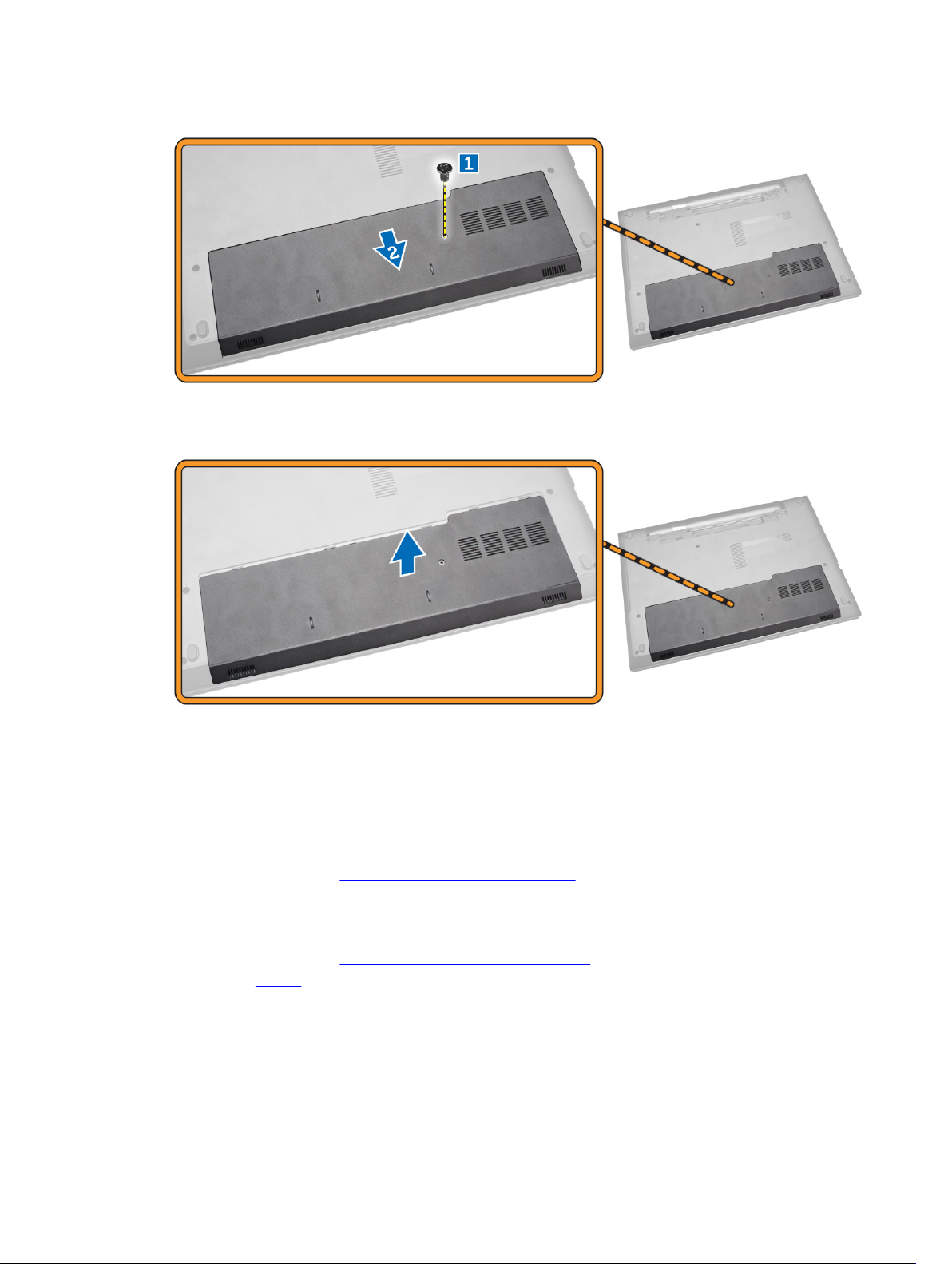
Removing the Hard Drive
1. Follow the procedures in Before Working Inside Your Computer.
2. Remove the battery.
3. Remove the access panel.
4. Perform the following steps as shown in the illustration:
a. Remove the screw that secures the hard drive to the computer [1].
b. Slide the hard drive out from the computer [2].
12
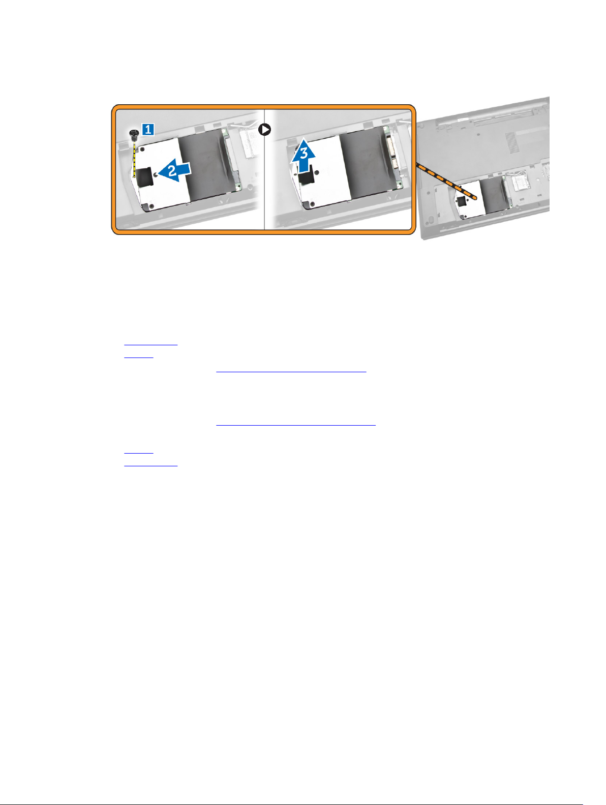
c. Lift the hard drive upwards from the computer [3].
Installing the Hard Drive
1. Slide the hard drive into the connector.
2. Tighten the screw to secure it to the chassis.
3. Install:
a. access panel
b. battery
4. Follow the procedures in After Working Inside Your computer.
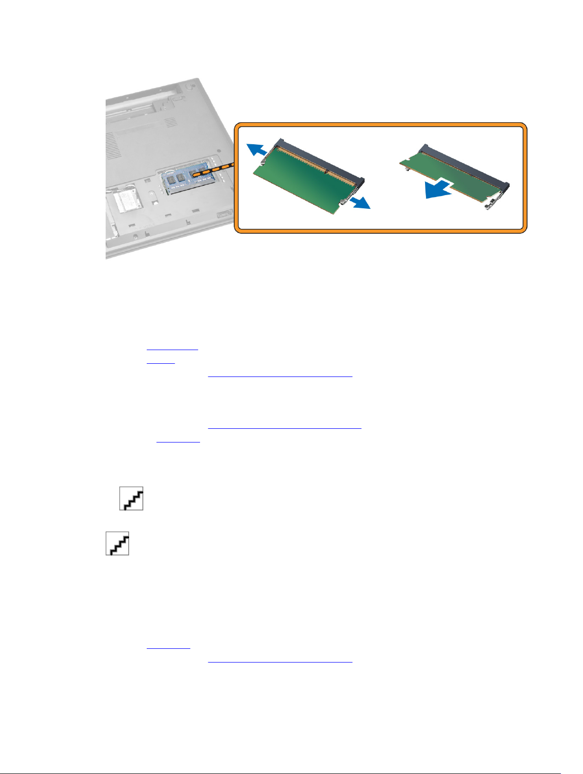
Removing the Memory Module
1. Follow the procedures in Before Working Inside Your Computer.
2. Remove:
a. battery
b. access panel
3. Pry the securing clips away from the memory module until it pops up.
4. Remove the memory module from its socket on the system board.
13
Installing the Memory Module
1. Insert the memory module into the socket and press to lock the securing clips.
2. Install the access panel.
3. Install the battery.
4. Follow the procedures in After Working Inside Your computer.
Removing the WLAN Card
1. Follow the procedures in Before Working Inside Your Computer.
2. Remove the base cover.
3. Perform the following steps to remove the WLAN card:
a. Disconnect the WLAN cables from its connectors [1].
b. Remove the screw that secures the WLAN card to the computer [2].
4. Pull the WLAN card to remove from the computer.
Installing the WLAN Card
1. Place the WLAN card into its slot on the computer.
2. Connect the WLAN cables to its connectors on the WLAN Card.
3. Tighten the screw that secures the WLAN card to the computer.
4. Install the base cover.
5. Follow the procedures in After Working Inside Your computer.
14
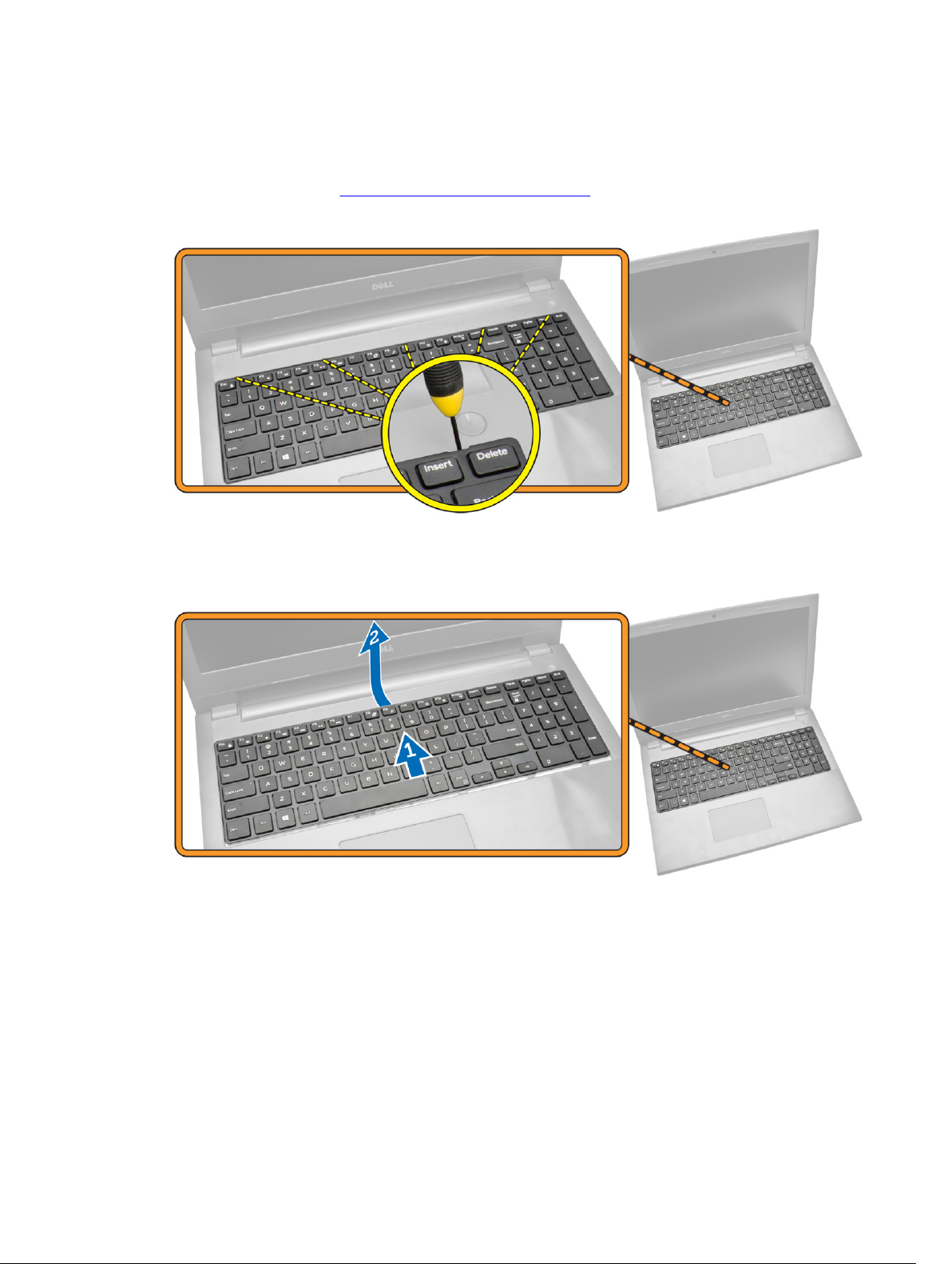
Removing the Keyboard
1. Follow the procedures in Before Working Inside Your Computer.
2. Release the keyboard by pressing the tabs using a scribe.
3. Perform the following steps as shown in the illustration:
a. Slide the keyboard from the computer [1].
b. Flip the keyboard to access the cable below [2].
4. Perform the following steps as shown in the illustration:
a. Lift the locking tab and disconnect the cable from the locking tab [1].
b. Disconnect the keyboard cable from the computer [2].
15
 Loading...