

Page 1

VEP4600
Setup Guide
Page 2

Notes, cautions, and warnings
NOTE: A NOTE indicates important information that helps you make better use of
your product.
CAUTION: A CAUTION indicates either potential damage to hardware or loss of data
and tells you how to avoid the problem.
WARNING: A WARNING indicates a potential for property damage, personal injury,
or death.
Copyright © 2018 Dell Inc. or its subsidiaries. All rights reserved. Dell, EMC, and other trademarks are
trademarks of Dell Inc. or its subsidiaries. Other trademarks may be trademarks of their respective
owners.
2018 - 04
Rev. A00
Page 3

Contents
1 About this guide...............................................................................5
Related documents................................................................................... 6
Information symbols..................................................................................6
2 Site preparations............................................................................. 7
Site selection..............................................................................................7
Cabinet placement.................................................................................... 8
Rack mounting...........................................................................................8
System ground...........................................................................................8
Fans and airow........................................................................................ 8
Power..........................................................................................................9
Storing components..................................................................................9
3 VEP4600 installation......................................................................10
Unpack...................................................................................................... 10
Ground cable.............................................................................................11
Rack or cabinet installation.....................................................................12
Rack mount safety considerations...................................................13
Two-post installation................................................................................13
1U front-rack installation................................................................... 14
Four-post installation...............................................................................16
Optics installation.....................................................................................18
Optics removal................................................................................... 18
Platform power-up.................................................................................. 19
Power up sequence...........................................................................19
4 Specications............................................................................... 20
Chassis physical design.......................................................................... 20
Contents
3
Page 4

5 Support.........................................................................................23
4 Contents
Page 5
About this guide
This guide provides site preparation recommendations, step-by-step procedures for rack
mounting and desk mounting, inserting modules, and connecting to a power source.
CAUTION: To avoid electrostatic discharge (ESD) damage, wear grounding wrist
straps when handling this equipment.
WARNING: Only trained and qualied personnel can install this equipment. Read this
guide before you install and power up this equipment. This equipment contains two
power cords. Disconnect both power cords before servicing.
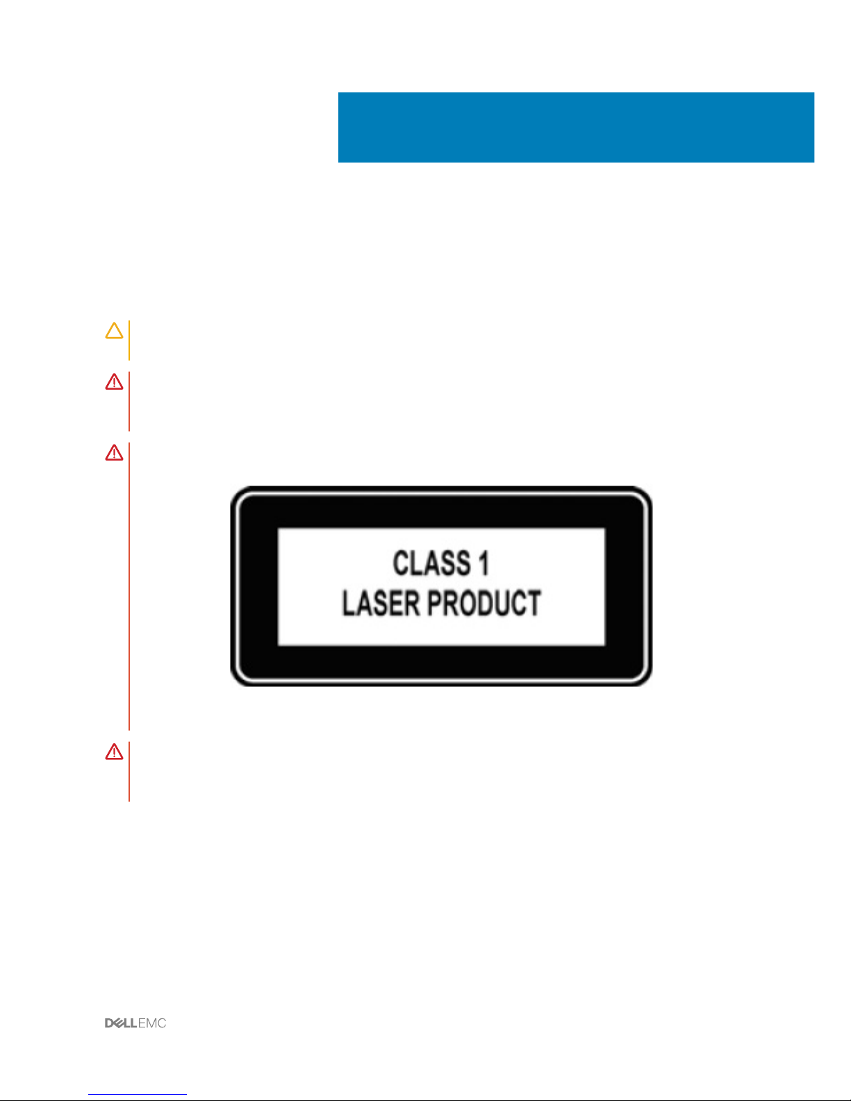
WARNING: This equipment contains optical transceivers, which comply with the
limits of Class 1 laser radiation.
Figure 1. Class 1 laser product tag
WARNING: When no cable is connected, visible and invisible laser radiation may be
emitted from the aperture of the optical transceiver ports. Avoid exposure to laser
radiation, and do not stare into open apertures.
Topics:
• Related documents
• Information symbols
1
About this guide 5
Page 6

Related documents
For more information about the Virtual Edge Platform 4600 (VEP4600), see the following
documents:
• VEP4600 Installation Guide
• VEP4600 Release Notes
NOTE: For the most recent documentation, see the support site: www.dell.com/
support.
Information symbols
This book uses the following information symbols:
NOTE: The Note icon signals important operational information.
CAUTION: The Caution icon signals information about situations that could result in
equipment damage or loss of data.
WARNING: The Warning icon signals information about hardware handling that
could result in injury.
WARNING: The ESD Warning icon requires that you take electrostatic precautions
when handling the device.
6 About this guide
Page 7

Site preparations
VEP4600 is universal customer premise equipment (uCPE). To connect the service provider
edge or enterprise branch to the cloud, use VEP4600 to host multiple virtual network
functions (VNFs), such as SD-WAN, routing, rewall, and deep-packet inspection.
For more information about VEP4600 specications, see Chassis physical design.
NOTE: Install the platform into a rack or cabinet before installing any optional
components.
Topics:
• Site selection
• Cabinet placement
• Rack mounting
• System ground
• Fans and airow
• Power
• Storing components
Site selection
Install your equipment in restricted access areas. A restricted access area is one where
service personnel can only gain access using a special tool, lock, key, or other means of
security. The authority responsible for the location controls access to the restricted area.
Ensure that the area where you install your platform meets the following safety
requirements:
• Near an adequate power source. Connect the platform to the appropriate branch circuit
protection according to your local electrical codes.
• Environmental—platform location—continuous temperature range is from 0°C to 45°C
(32°F to 113°F).
2
Site preparations 7
Page 8

• Operating humidity is from 5 to 90 percent non-condensing, continuous.
• In a dry, clean, well-ventilated, and temperature-controlled room, away from heat sources
such as hot cooling vents or direct sunlight.
• Away from sources of severe electromagnetic noise.
• Positioned in a rack or cabinet, or on a desktop with adequate space in the front, back,
and sides for proper ventilation and access.
• Install the platform in Information Technology Rooms in accordance with Article 645 of
the National Electrical Code and NFPA 75.
For more information about platform storage and environmental temperatures, see
Specications.
Cabinet placement
Install VEP4600 only in indoor cabinets designed for use in a controlled environment.
Do not install the platform in outside cabinets. For cabinet placement requirements, see Site
selection.
The cabinet must meet minimum size requirements. Airow must be in accordance with the
Electronic Industries Alliance (EIA) standard. Ensure that there is a minimum of 5 inches
(12.7 cm) between the intake and exhaust vents and the cabinet wall.
Rack mounting
When you prepare your equipment rack, ensure that the rack is grounded. Ground the
equipment rack to the same ground point the power service in your area uses. The ground
path must be permanent.
System ground
Dell recommends grounding your system. Use VEP4600 in a CBN.
Fans and airow
Fan installation is done as part of the factory install based on stock keeping unit (SKU) type.
VEP 4600 supports an AC normal fan unit with fan airow from the I/O to the PSU.
8
Site preparations
Page 9

For proper ventilation, position the platform in an equipment rack or cabinet with a minimum
of 5 inches (12.7 cm) of clearance around the exhaust vents. The fan speed varies based on
internal temperature monitoring. The platform never intentionally turns o the fans.
Power
Connect the platform to the applicable power source using the appropriate power cable. An
AC power cable is included with the platform.
When installing AC platforms, follow the requirements of the National Electrical Code ANSI/
NFPA 70, where applicable.
The platform is powered-up when the power cable is connected between the platform and
the power source.
CAUTION: Always disconnect the power cable before you service the power supply
slots. The platform has multiple power cords. Before servicing, ensure that all power
cords are disconnected.
CAUTION: Use the power supply cable as the main disconnect device. Ensure that
the socket-outlet is located/installed near the equipment and is easily accessible.
Storing components
If you do not install the VEP4600 and components immediately, properly store the platform
and all optional components following these guidelines:
• Storage location temperature must remain constant. The storage range is from -40°C to
70°C (-40°F to 158°F).
• Store on a dry surface or oor, away from direct sunlight, heat, and air conditioning
ducts.
• Store in a dust-free environment.
NOTE
: ESD damage can occur when components are mishandled. Always wear an
ESD-preventive wrist or heel ground strap when handling the platform and its
accessories. After you remove the original packaging, place the VEP4600 and its
components on an anti-static surface.
Site preparations 9
Page 10

VEP4600 installation
To install VEP4600, complete the installation procedures in the order presented in this
section.
Always handle the platform and its components with care. Avoid dropping the platform or
any eld replaceable units (FRUs).
NOTE: ESD damage can occur if components are mishandled. Always wear an ESD-
preventive wrist or heel ground strap when handling the platform and its
components. As with all electrical devices of this type, take all the necessary safety
precautions to prevent injury when installing this platform.
Topics:
• Unpack
• Ground cable
• Rack or cabinet installation
• Two-post installation
• Four-post installation
• Optics installation
• Platform power-up
Unpack
NOTE
: Before unpacking the platform, inspect the container and immediately report
any evidence of damage.
When unpacking VEP4600, make sure that the following items are included:
• One VEP4600
• One RJ-45 to DB-9 female cable
3
10 VEP4600 installation
Page 11

• Two-post rail kit, no tools required
• One or two AC PSUs, depending on the conguration
• Five AC normal fan units
• One or two country- and region-specic AC power cords, depending on the
conguration
• Ground lug kit (included in the accessories box)
• VEP4600 Setup Guide
• Safety and Regulatory Information
• Warranty and Support Information
1 Place the container on a clean, at surface and cut all straps securing the container.
2 Open the container.
3 Carefully remove the platform from the container and place it on a secure and clean
surface.
4 Remove all packing material.
5 Inspect the product and accessories for damage.
Ground cable
To attach a ground cable to the switch, use the included two M3 ground lug bracket screws.
The switch ships with the M3 ground lug bracket screws attached.
NOTE: For AC-powered platforms, although the third conductor of the AC power
cord provides a ground path, Dell EMC recommends grounding your platform with a
dedicated ground wire.
The ground cable is not included. To properly ground the platform, Dell EMC recommends a
one- or two-hole lug, M3 hole size. The ground lug must be a UL-recognized, crimp-type lug.
CAUTION
: Grounding conductors
must
be made of copper. Do not use aluminum
conductors.
NOTE: Coat the one-hole lug with an anti-oxidant compound before crimping. Also,
bring any unplated mating surfaces to a shiny nish and coat with an anti-oxidant
before mating. Plated mating surfaces must be clean and free from contamination.
NOTE: The rack installation ears are not suitable for grounding.
VEP4600 installation 11
Page 12
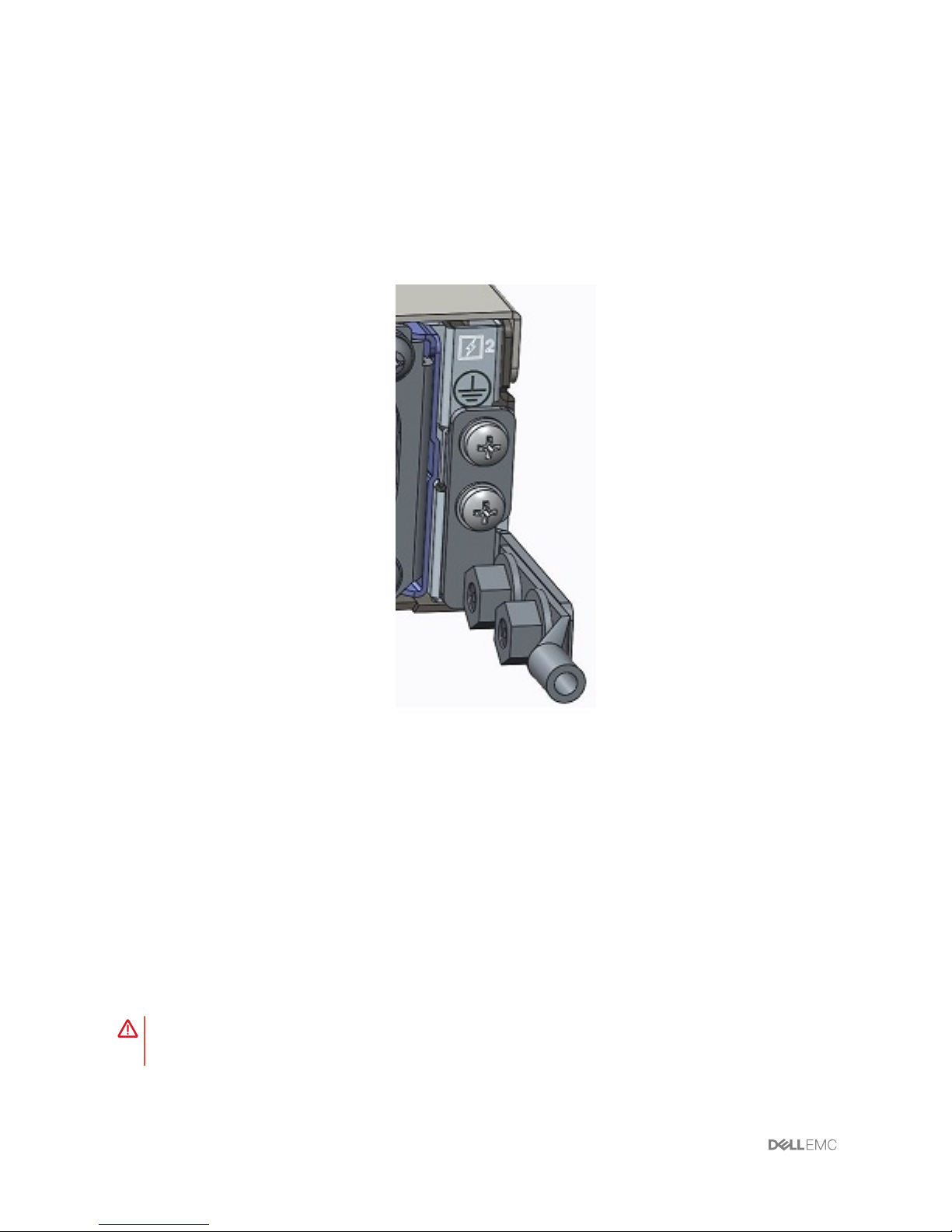
Before you install the switch into the dual-tray:
1 Cut the ground cable (not included) to the desired length. The cable length must
facilitate proper operation of the fault interrupt circuits. Use the shortest cable route
allowable.
2 Unscrew the two attached M3 screws and set aside.
3 Attach the ground lug and bracket to the switch using the M3 screws.
Figure 2. VEP4600 ground lug attached
4 Attach the other end of the ground cable to a suitable ground point such as the rack or
cabinet.
Rack or cabinet installation
You may either place the platform on a rack shelf or mount the platform directly into a 19"
wide, EIA-310- E-compliant rack.
The platform includes two-post rail assemblies.
WARNING
: This guide is a condensed reference. Read the safety instructions in
your
Safety, Environmental, and Regulatory
information booklet before you begin.
12 VEP4600 installation
Page 13

NOTE: The illustrations in this section are not intended to represent a specic
platform.
NOTE: Do not the use the mounted two-post rails as a shelf or a workplace.
Rack mount safety considerations
• Rack loading—Overloading or uneven loading of racks may result in shelf or rack failure,
possibly damaging the equipment and causing personal injury. Stabilize racks in a
permanent location before loading begins. Mount the components starting at the bottom
of the rack, then work to the top. Do not exceed your rack’s load rating.
• Power considerations—Connect only to the power source specied on the unit. When
you install multiple electrical components in a rack, ensure that the total component
power ratings do not exceed the circuit capabilities. Overloaded power sources and
extension cords present re and shock hazards.
• Elevated ambient temperature—If you install the platform in a closed rack assembly, the
operating temperature of the rack environment may be greater than the room ambient
temperature. Use care not to exceed the 45°C (113°F) maximum ambient temperature
of the platform.
• Reduced air ow—Do not compromise the amount of airow required for safe operation
of the equipment. Install the equipment in the rack so that the equipment constantly has
the correct amount of airow surrounding it.
• Reliable earthing—Maintain reliable earthing of rack-mounted equipment. Pay particular
attention to the supply connections other than the direct connections to the branch
circuit, for example; use of power strips.
• Do not mount the equipment with the fan panel facing in the downward position.
Two-post installation
To easily congure your rack for installation of the VEP4600, use the two-post rack
mounting system provided. To complete this installation, supply four rack-mounting screws.
NOTE
: To be NEBS-compliant, you must install the VEP4600 in a four-post rack.
To begin installation, separate each rail assembly by sliding the inside rail out of the outside
rail.
NOTE
: For more installation instructions, see the installation labels attached to the
rail assembly.
VEP4600 installation 13
Page 14
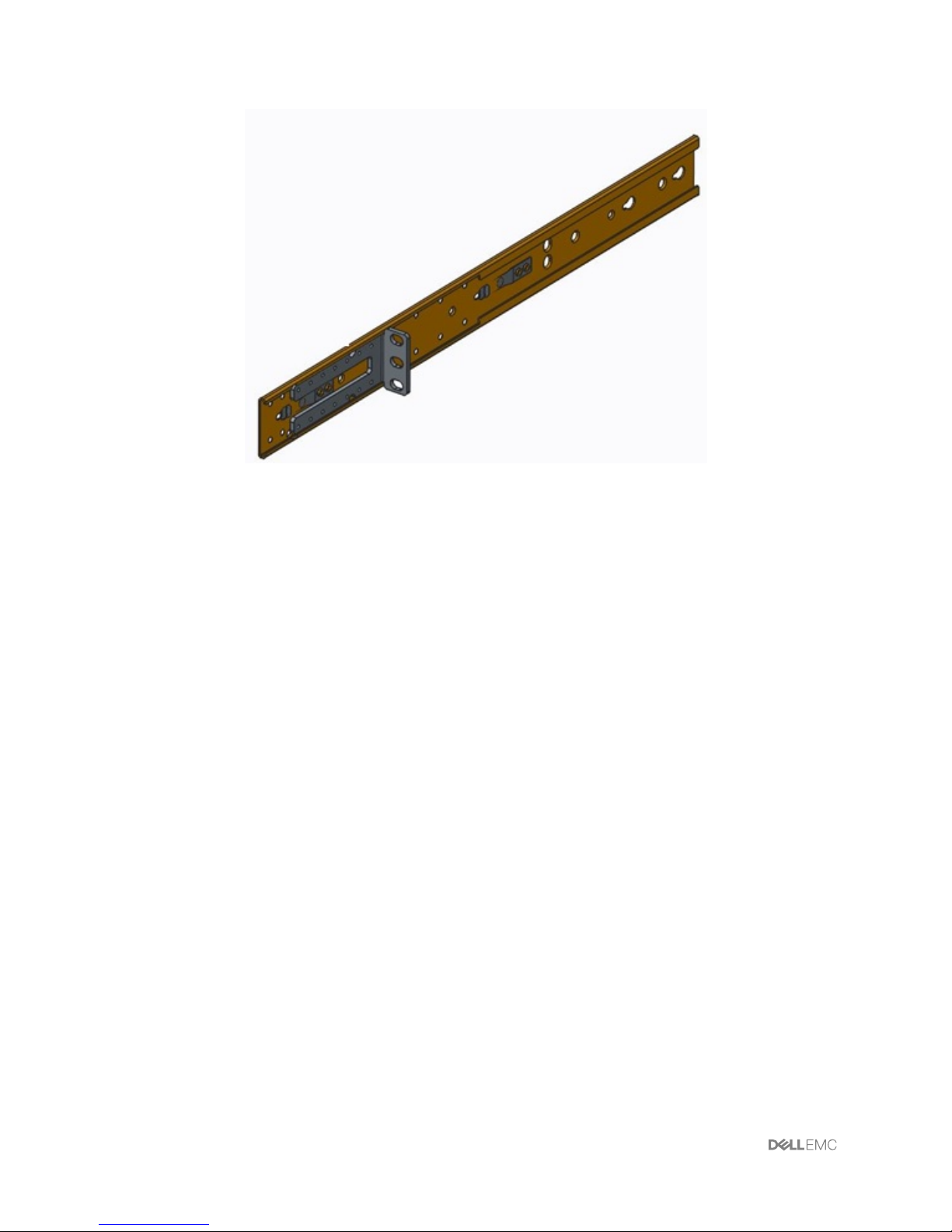
Figure 3. Two-post rail
1U front-rack installation
1 Attach the inner platform rails to the VEP4600.
Line up the half-holes on the rail with the mounting heads on the platforms and attach
the rail to the platform. Slide the rail back until it locks into place.
14
VEP4600 installation
Page 15
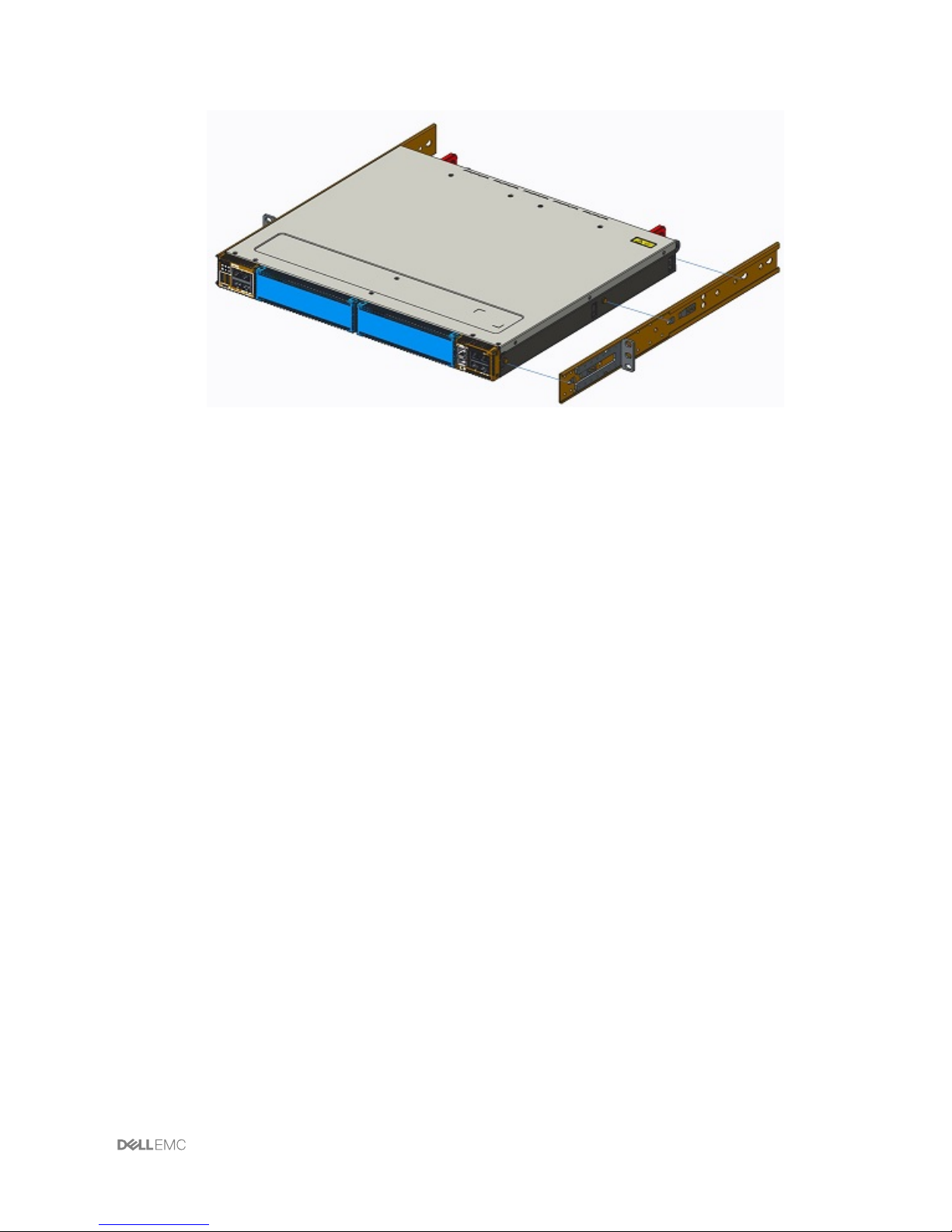
Figure 4. Platfrom rail attachment
2 Repeat on the other side of the platform.
3 Attach the outer platform rails to the two-post rack rails using two user-supplied
screws on each side.
4 After you install both rails, line up the platform rails with the installed rack rails. Slide the
platform in until it is ush with the front of rack.
About three inches before you fully insert your platform, the rail locking feature engages
to keep the platform from inadvertently sliding out and falling.
VEP4600 installation 15
Page 16
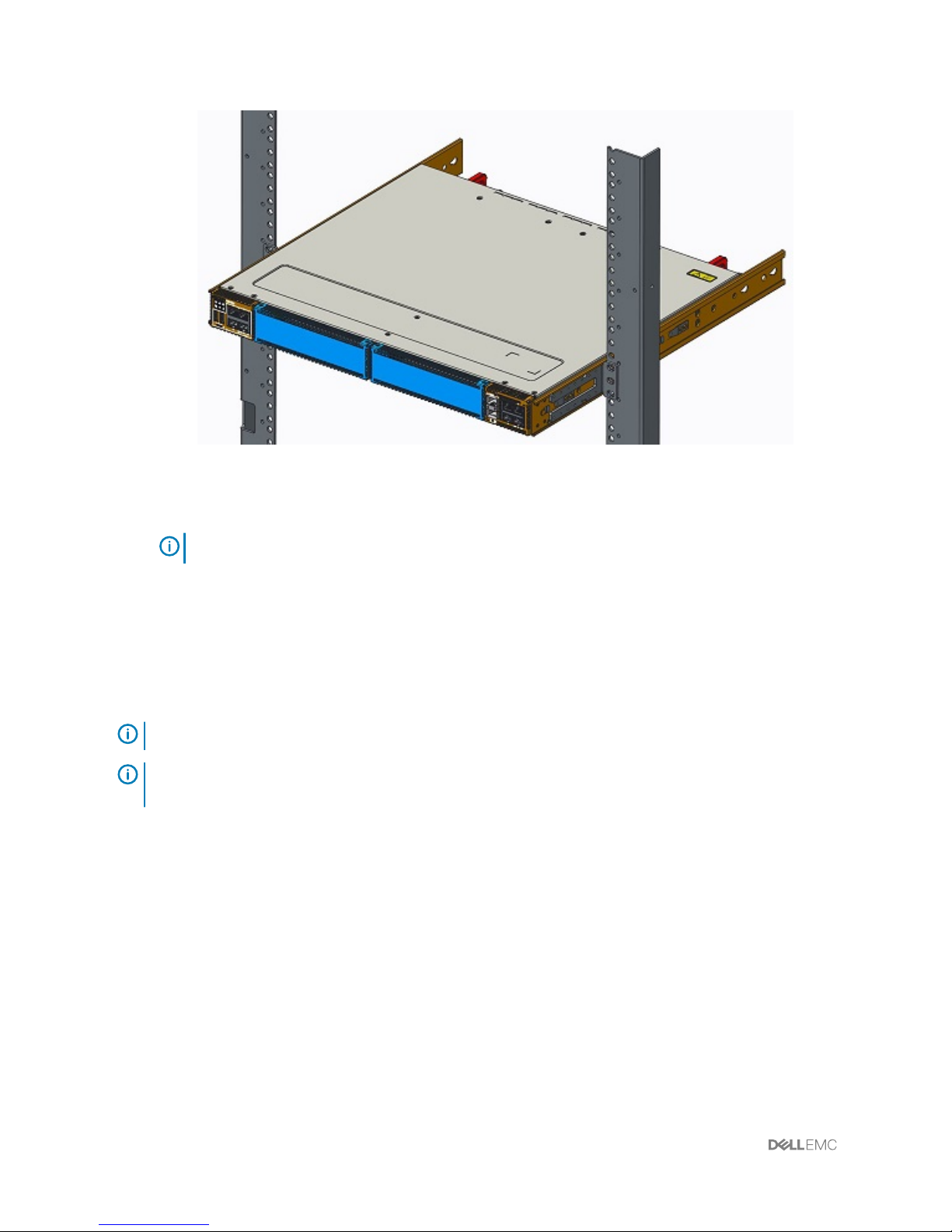
Figure 5. Platform two-post installed
NOTE: Do not the use the mounted rails as a shelf or a workplace.
To remove the platform, unscrew the rack-mounting screws and slide the platform forward.
Four-post installation
To complete this installation, supply eight rack mounting screws.
NOTE
: The following installation instructions are for NEBS-compliant platforms.
NOTE: For more installation instructions, see the installation labels attached to the
rail assembly.
1 Separate each rail assembly by sliding the inside rail out of the outside rail.
2 Attach the inner platform rails to the VEP4600.
Line up the half-holes on the rail with the mounting heads on the platforms and attach
the rail to the platform. Slide the rail back until it locks into place.
16
VEP4600 installation
Page 17
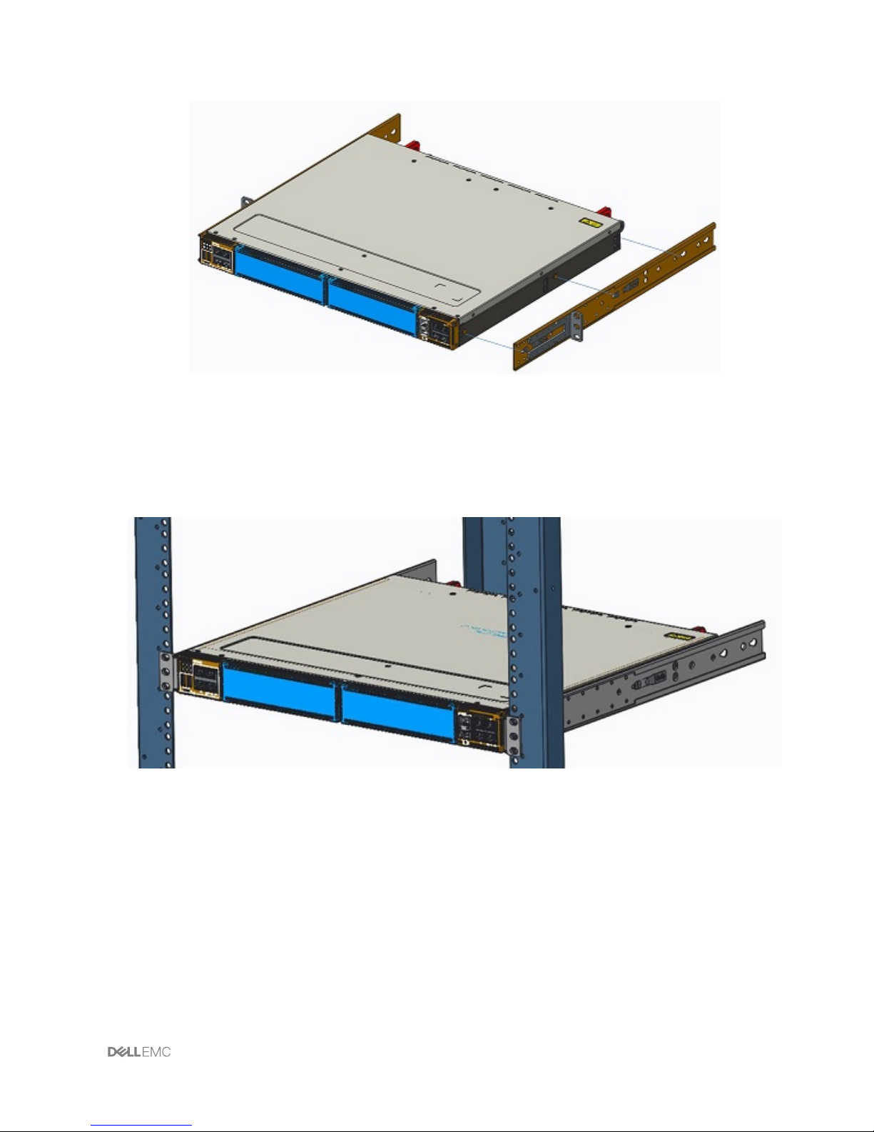
Figure 6. Platform rail attachment
3 Repeat on the other side of the platform.
4 Attach the platform rails to the four-post rack rails using two user-supplied screws on
each side.
Figure 7. Platform four-post front installed
5 Slide the rear platform rail from the back to the front bracket. Secure with two user-
supplied screws on each side.
VEP4600 installation
17
Page 18
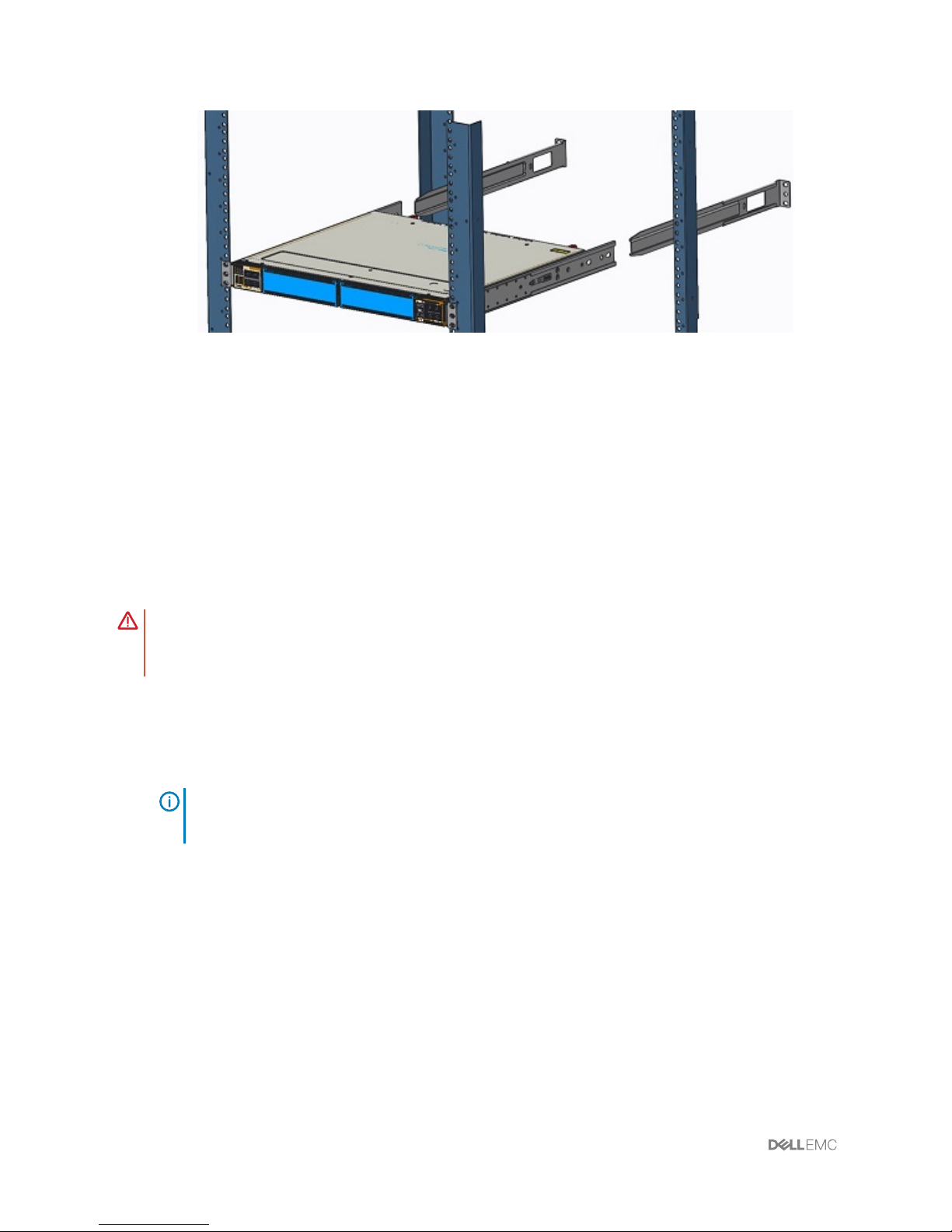
Figure 8. Platform four-post rear installed
About three inches before you fully insert your platform, the rail locking feature engages
to keep the platform from inadvertently sliding out and falling.
To remove the platform, unscrew the rack-mounting screws and slide the platform forward.
Optics installation
WARNING: When working with optical bers, follow all warning labels and always
wear eye protection. Never look directly into the end of a terminated or
unterminated ber or connector as it may cause eye damage.
1 Position the optic so it is in the correct position.
The optic has a key that prevents it from being inserted incorrectly.
2 Insert the optic into the port until it gently snaps into place.
NOTE
: When you cable the ports, be sure not to interfere with the airow from
the small vent holes above and below the ports.
Optics removal
Remove an optic by pushing the tab on the optic and sliding the optic from the port.
When removing optics with direct attach cables (DACs) from the port, pull the release tab
rmly and steadily. Before pulling the release tab, you may need to gently push the optic into
the port to ensure that it is seated properly. Do not jerk or tug repeatedly on the tab.
18
VEP4600 installation
Page 19

Platform power-up
Supply power to the VEP4600 after you mount it in a rack or cabinet.
Reinspect your platform before power-up. Verify the following:
• The equipment is properly secured to the rack. Dell EMC recommends properly
grounding the platform.
• The ambient temperature around the unit, which may be higher than the room
temperature, is within the limits specied for the VEP4600, see Specications.
• There is sucient airow around the unit.
• The input circuits are correctly sized for the loads and that you use sucient overcurrent
protection devices.
• All protective covers are in place.
• Blank panels are installed if you do not install optional modules.
CAUTION: Do not power up the platform if you did not install a fan module.
NOTE: A US AC power cable is included for powering up an AC power supply. You
must order all other power cables separately.
NOTE: ESD damage can occur if components are mishandled. Always wear an ESD-
preventive wrist or heel ground strap when handling the platform and its
components.
Power up sequence
When the platform powers up, the fans immediately come on at high speed. The fan speed
slows as the platform continues to boot up.
VEP4600 installation
19
Page 20

Specications
This section lists the VEP4600 specications.
CAUTION: Operate the product at an ambient temperature not higher than 0°C to
45°C (32°F to 113°F).
CAUTION: Lithium Battery Caution: There is a danger of explosion if the battery is
incorrectly replaced. Replace only with same or equivalent type of battery. Dispose
of the batteries according to the manufacturer's instructions.
NOTE: For RoHS information, see Restricted Material Compliance.
Chassis physical design
Table 1. Chassis physical design
Parameter Specications
Height 1.75 inches (44 mm)
Width 17.1 inches (434 mm)
Depth
15 inches (381 mm)
PSU/fan tray handle: 1.57 inches (40 mm)
Chassis weight with factory-installed
components
• 13.75 lbs (6.24 kg) (1 PSU and 4 fans)
• 13.90 lbs (6.30 kg) (1 PSUs and 5 fans)
• 15.75 lbs (7.14 kg) (2 PSUs and 5 fans)
Rack clearance required
Front: 5 inches (12.7 cm)
4
20 Specications
Page 21

Parameter Specications
Back: 5 inches (12.7 cm)
Table 2. Environmental parameters
Parameter Specications
Operating temperature 0°C to 45°C (23°F to 113°F) continuously
-5°C to 45°C (23°F to 113°F) short term
Short term is </= 1% of operational hours
per year.
NOTE: Reduce maximum
temperature by 1°C/125 meters
(1°F/228 feet) above 950 meters
(3,117 feet).
Operating humidity 5% to 90% (RH), non-condensing
Storage temperature –40° to 70°C (–40° to 158°F )
Storage humidity 5% to 90%, non-condensing
Maximum thermal output 500 W = 1706 BTU/Hr
Maximum operational altitude 10,000 feet (3,048 meters)
Maximum non-operational altitude 35,000 feet (10,668 meters)
Shock Dell EMC Spec SV0115
Table 3. AC power requirements
Parameter Specications
Power supply 100–240 VAC 50/60 Hz
Maximum current draw per system 5A/4.17A at 100/120V AC 2.5A/2.1A at
200/240V AC
Maximum power consumption*
• 5-fan 16-core CPU: 300W
• 4-fan 8-core CPU: 230W
Specications 21
Page 22

Parameter Specications
• 4-fan 4-core CPU: 220W
Typical power consumption* 240W
*For the most current power consumption specications, see the Installation Guide at
www.Dell.com/support.
22 Specications
Page 23

Support
The support site provides documents and tools to help you eectively use your equipment
and mitigate network outages. Through the support site you can obtain technical
information, access software upgrades and patches, download available management
software, and manage your open cases. The support site provides integrated, secure access
to these services.
To access the support site, go to www.dell.com/support/. To display information in your
language, scroll down to the bottom of the web page and select your country from the dropdown menu.
• To obtain product-specic information, enter the 7-character service tag, known as a
luggage tag, or 11-digit express service code of your platform and click Submit.
To view the chassis service tag or express service code, pull out the tag on the upperright side of the platform.
• To receive more technical support, click Contact Us. On the Contact Information web
page, click
Technical Support.
To access platform documentation, go to www.dell.com/manuals/.
To search for drivers and downloads, go to www.dell.com/drivers/.
To participate in community blogs and forums, go to www.dell.com/community.
5
Support 23
 Loading...