

Dell Storage NX430 User Manual

Dell EMC NX430 System
Owner's Manual
Regulatory Model: E34S Series
Regulatory Type: E34S001

Notes, cautions, and warnings
NOTE: A NOTE indicates important information that helps you make better use of your computer.
CAUTION: A CAUTION indicates either potential damage to hardware or loss of data and tells you how to avoid the problem.
WARNING: A WARNING indicates a potential for property damage, personal injury, or death.
© 2016 - 2019 Dell Inc. or its subsidiaries. All rights reserved. Dell, EMC, and other trademarks are trademarks of Dell Inc. or its subsidiaries. Other
trademarks may be trademarks of their respective owners.
2019 - 02
Rev. A01

Contents
1 About your system..........................................................................................................................................7
Supported congurations..................................................................................................................................................7
Front panel features and indicators..................................................................................................................................7
LCD panel......................................................................................................................................................................8
Back panel features and indicators.................................................................................................................................10
Hot swappable hard drive indicator codes.....................................................................................................................12
iDRAC Direct LED indicator codes..................................................................................................................................12
NIC indicator codes..........................................................................................................................................................14
Indicator codes for redundant power supply unit.........................................................................................................14
Locating Service Tag of your system.............................................................................................................................16
2 Documentation resources............................................................................................................................. 17
3 Technical specications................................................................................................................................19
Dimensions and weight....................................................................................................................................................19
Processor specications..................................................................................................................................................19
Expansion bus specications...........................................................................................................................................19
Memory specications.................................................................................................................................................... 20
Power specications........................................................................................................................................................20
Drive specications..........................................................................................................................................................20
Connectors specications............................................................................................................................................... 21
Video specications..........................................................................................................................................................21
Expanded operating temperature...................................................................................................................................21
Environmental specications.......................................................................................................................................... 22
4 Initial system setup and conguration.......................................................................................................... 24
Setting up your system................................................................................................................................................... 24
iDRAC conguration........................................................................................................................................................ 24
Options to set up iDRAC IP address........................................................................................................................24
Log in to iDRAC..........................................................................................................................................................25
Reinstalling the NAS operating system by using DVD.................................................................................................25
5 Pre-operating system management applications..........................................................................................26
Options to manage the pre-operating system applications........................................................................................26
System Setup...................................................................................................................................................................26
Viewing System Setup.............................................................................................................................................. 26
System Setup details.................................................................................................................................................26
System BIOS...............................................................................................................................................................27
iDRAC Settings utility.................................................................................................................................................41
Device Settings...........................................................................................................................................................41
Dell Lifecycle Controller...................................................................................................................................................42
Embedded systems management............................................................................................................................42
Boot Manager...................................................................................................................................................................42
Contents
3

Viewing Boot Manager..............................................................................................................................................42
Boot Manager main menu.........................................................................................................................................42
6 Installing and removing system components................................................................................................ 44
Safety instructions...........................................................................................................................................................44
Before working inside your system................................................................................................................................45
After working inside your system...................................................................................................................................45
Recommended tools........................................................................................................................................................45
Front bezel (optional)......................................................................................................................................................45
Installing the optional front bezel.............................................................................................................................45
Removing the optional front bezel...........................................................................................................................46
System cover....................................................................................................................................................................46
Removing the system cover.....................................................................................................................................46
Installing the system cover........................................................................................................................................47
Inside the system............................................................................................................................................................. 48
Intrusion switch................................................................................................................................................................49
Removing the intrusion switch.................................................................................................................................49
Installing the intrusion switch...................................................................................................................................50
Cooling shroud................................................................................................................................................................. 50
Removing the cooling shroud...................................................................................................................................50
Installing the cooling shroud......................................................................................................................................51
System memory................................................................................................................................................................51
General memory module installation guidelines......................................................................................................52
Mode-specic guidelines.......................................................................................................................................... 53
Sample memory congurations................................................................................................................................54
Removing memory modules..................................................................................................................................... 54
Installing memory modules....................................................................................................................................... 55
Hard drives........................................................................................................................................................................56
Supported hard drive conguration.........................................................................................................................57
Removing a 3.5-inch hot swappable hard drive carrier blank...............................................................................57
Installing a 3.5-inch hot swappable hard drive carrier blank.................................................................................58
Removing a hot swappable hard drive carrier........................................................................................................58
Installing a hot swappable hard drive carrier.......................................................................................................... 59
Installing a 2.5-inch hot swappable hard drive into a 3.5-inch hard drive adapter.............................................60
Removing a 2.5-inch hot swappable hard drive from a 3.5-inch hard drive adapter......................................... 61
Installing a 3.5-inch hard drive into the 3.5-inch hot swappable hard drive carrier............................................61
Removing a 3.5-inch hard drive from a 3.5-inch hot swappable hard drive carrier............................................61
Optical drive (optional)....................................................................................................................................................62
Removing the optional optical drive........................................................................................................................ 62
Installing the optional optical drive...........................................................................................................................63
Cooling fans......................................................................................................................................................................64
Removing the cooling fan blank...............................................................................................................................64
Installing the cooling fan blank................................................................................................................................. 65
Removing a cooling fan.............................................................................................................................................66
Installing a cooling fan................................................................................................................................................67
Expansion cards and expansion card riser.................................................................................................................... 67
Expansion card installation guidelines......................................................................................................................67
Contents
4

Removing the expansion card riser..........................................................................................................................69
Installing the expansion card riser............................................................................................................................70
Removing an expansion card....................................................................................................................................70
Installing an expansion card.......................................................................................................................................71
Removing the internal PERC card........................................................................................................................... 72
Installing the internal PERC card..............................................................................................................................73
iDRAC port card (optional)..............................................................................................................................................74
Replacing an optional SD vFlash card......................................................................................................................74
Removing the optional iDRAC port card................................................................................................................. 74
Installing the optional iDRAC port card................................................................................................................... 75
Processor and heat sink..................................................................................................................................................76
Removing a processor...............................................................................................................................................76
Installing a processor................................................................................................................................................. 78
Power supply units...........................................................................................................................................................80
Hot spare feature.......................................................................................................................................................80
Removing a redundant power supply unit.............................................................................................................. 80
Installing a redundant power supply unit..................................................................................................................81
Removing the power supply unit blank................................................................................................................... 82
Installing the power supply unit blank......................................................................................................................82
System battery.................................................................................................................................................................83
Replacing the system battery...................................................................................................................................83
Hard drive backplane.......................................................................................................................................................84
Removing the hard drive backplane........................................................................................................................84
Installing the hard drive backplane...........................................................................................................................86
Control panel assembly....................................................................................................................................................87
Removing the LCD control panel assembly............................................................................................................ 87
Installing the LCD control panel assembly.............................................................................................................. 89
Power interposer board...................................................................................................................................................89
Removing the power interposer board....................................................................................................................89
Installing the power interposer board......................................................................................................................90
Trusted Platform Module.................................................................................................................................................91
Installing the Trusted Platform Module....................................................................................................................91
Reenabling the TPM for TXT users.........................................................................................................................92
System board....................................................................................................................................................................92
Removing the system board.....................................................................................................................................92
Installing the system board....................................................................................................................................... 94
7 Using system diagnostics.............................................................................................................................98
Dell Embedded System Diagnostics..............................................................................................................................98
When to use the Embedded System Diagnostics..................................................................................................98
Running the Embedded System Diagnostics from Boot Manager......................................................................98
Running the Embedded System Diagnostics from the Dell Lifecycle Controller............................................... 98
System diagnostic controls.......................................................................................................................................99
8 Jumpers and connectors ........................................................................................................................... 100
System board jumper settings......................................................................................................................................100
System board connectors..............................................................................................................................................101
Contents
5

Disabling a forgotten password.....................................................................................................................................102
9 Troubleshooting your system......................................................................................................................103
Safety rst — for you and your system......................................................................................................................103
Troubleshooting system startup failure........................................................................................................................103
Troubleshooting external connections......................................................................................................................... 104
Troubleshooting the video subsystem......................................................................................................................... 104
Troubleshooting a USB device......................................................................................................................................104
Troubleshooting a serial I/O device..............................................................................................................................105
Troubleshooting a NIC................................................................................................................................................... 105
Troubleshooting a wet system......................................................................................................................................105
Troubleshooting a damaged system.............................................................................................................................106
Troubleshooting the system battery.............................................................................................................................107
Troubleshooting power supply units.............................................................................................................................107
Troubleshooting power source problems...............................................................................................................107
Power supply unit problems.................................................................................................................................... 107
Troubleshooting cooling problems................................................................................................................................108
Troubleshooting cooling fans.........................................................................................................................................108
Troubleshooting system memory..................................................................................................................................109
Troubleshooting an internal USB key........................................................................................................................... 109
Troubleshooting an SD card...........................................................................................................................................110
Troubleshooting an optical drive....................................................................................................................................110
Troubleshooting a tape backup unit...............................................................................................................................111
Troubleshooting a hard drive...........................................................................................................................................111
Troubleshooting expansion cards.................................................................................................................................. 112
Troubleshooting processors........................................................................................................................................... 113
10 Getting help...............................................................................................................................................114
Contacting Dell................................................................................................................................................................ 114
Documentation feedback...............................................................................................................................................114
Accessing system information by using QRL...............................................................................................................114
Quick resource locator..............................................................................................................................................115
6
Contents
About your system
The Dell Storage NX430 NAS system supports one processor based on the Intel E3-1200V5 series, up to four DIMMs, and up to four hard
drives or solid-state drives (SSDs).
Topics:
• Supported congurations
• Front panel features and indicators
• Back panel features and indicators
• Hot swappable hard drive indicator codes
• iDRAC Direct LED indicator codes
• NIC indicator codes
• Indicator codes for redundant power supply unit
• Locating Service Tag of your system
Supported congurations
The Dell Storage NX430 NAS system supports the following conguration:
1
Table 1. Supported
System Conguration
Four hard drive system Up to four 3.5-inch or four 2.5-inch hot-swappable hard drives in
congurations
3.5-inch hard drive adapters.
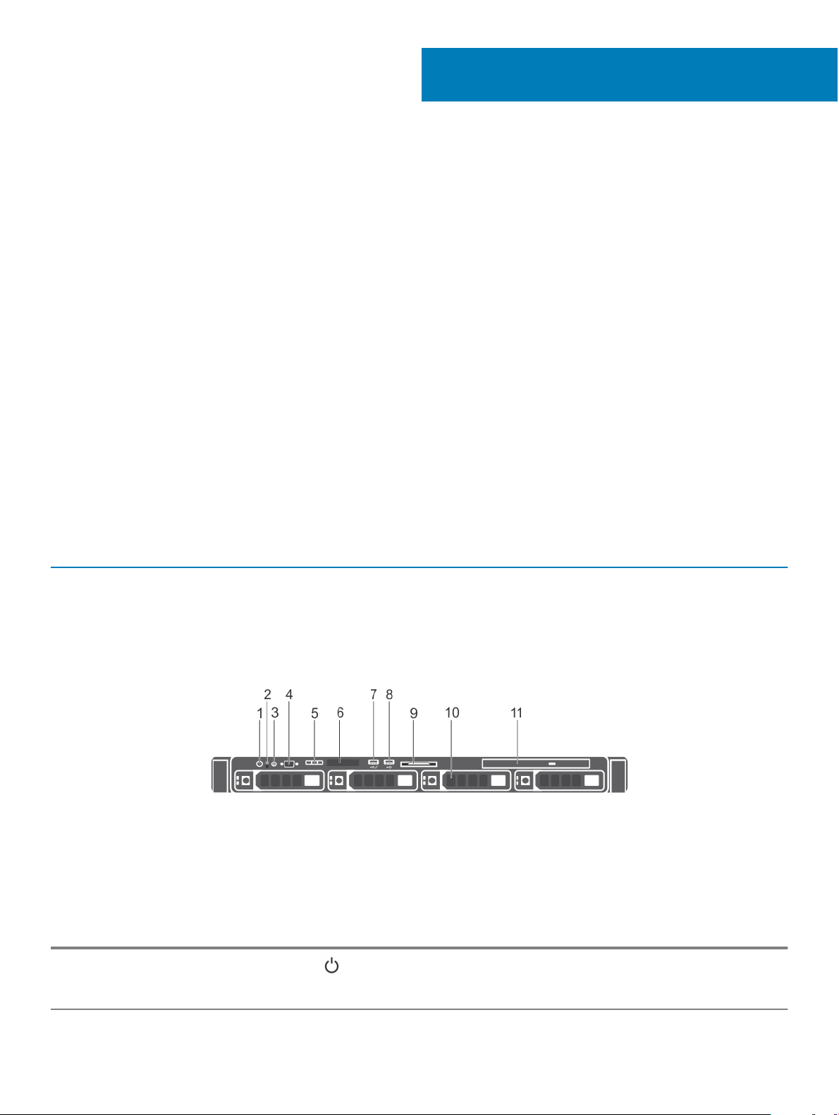
Front panel features and indicators
Figure 1. Front panel features and indicators — four 3.5-inch hot-swappable hard drive chassis
Table 2. Front panel features and indicators— four 3.5-inch hot-swappable hard drive chassis
Item Indicator, button, or connector Icon Description
1 Power-on indicator, power
button
Enables you to know the power status of the system. The power-on
indicator glows when the system power is on. The power button
controls the power supply output to the system.
About your system 7

Item Indicator, button, or connector Icon Description
NOTE: On ACPI-compliant operating systems, turning o
the system by pressing the power button causes the system
to perform a graceful shutdown before power to the system
is turned o.
2 NMI button
3 System identication button Enables you to locate a particular system within a rack. The
4 Video connector Enables you to connect a display to the system.
5 LCD menu buttons Enables you to navigate the control panel LCD menu.
6 LCD panel Displays system ID, status information, and system error messages.
Enables you to troubleshoot software and device driver errors when
running certain operating systems. This button can be pressed by
using the end of a paper clip.
Use this button only if directed to do so by qualied support personnel
or by the operating system's documentation.
identication buttons are on the front and back panels. When one of
these buttons is pressed, the LCD panel on the front and the system
status indicator on the back ash until one of the buttons is pressed
again.
Press the system identication button to turn the system ID on or o.
If the system stops responding during POST, press and hold the
system ID button for more than ve seconds to enter BIOS progress
mode.
To reset iDRAC (if not disabled in F2 iDRAC setup), press and hold the
button for more than 15 seconds.
See the LCD panel features section.
7 USB management port/iDRAC
managed USB port
8 USB connector Enables you to connect USB devices to the system. The port is USB
9 Information tag Contains system information such as service tag, NIC, MAC address
10 Hard drives slots Enables you to install up to four 3.5-inch hot-swappable hard drives or
11 Optical drive slot Enables you to install an optional slim SATA DVD-ROM drive or DVD
Functions as a regular USB port or provide access to the iDRAC
Direct features. For more information, see the iDRAC User’s Guide at
Dell.com/idracmanuals.
2.0-compliant.
for your reference. The information tag is a slide-out label panel.
four 2.5-inch hot-swappable hard drives in 3.5-inch hard drive
adapters.
+/-RW drive.
LCD panel
The LCD panel of your system provides system information, status, and error messages to indicate if the system is functioning correctly or
if the system needs attention. For more information about error messages, see the Dell Event and Error Messages Reference Guide at
Dell.com/openmanagemanuals >OpenManage software.
• The LCD backlight turns blue during normal operating conditions.
About your system
8
• When the system needs attention, the LCD turns amber, and displays an error code followed by descriptive text.
NOTE: If the system is connected to a power source and an error is detected, the LCD turns amber regardless of whether
the system is turned on or o.
• The LCD backlight is turned o when the system is in standby mode and can be turned on by pressing either the Select, Left, or Right
button on the LCD panel.
• The LCD backlight remains o if LCD messaging is turned o using the iDRAC utility, the LCD panel, or other tools.
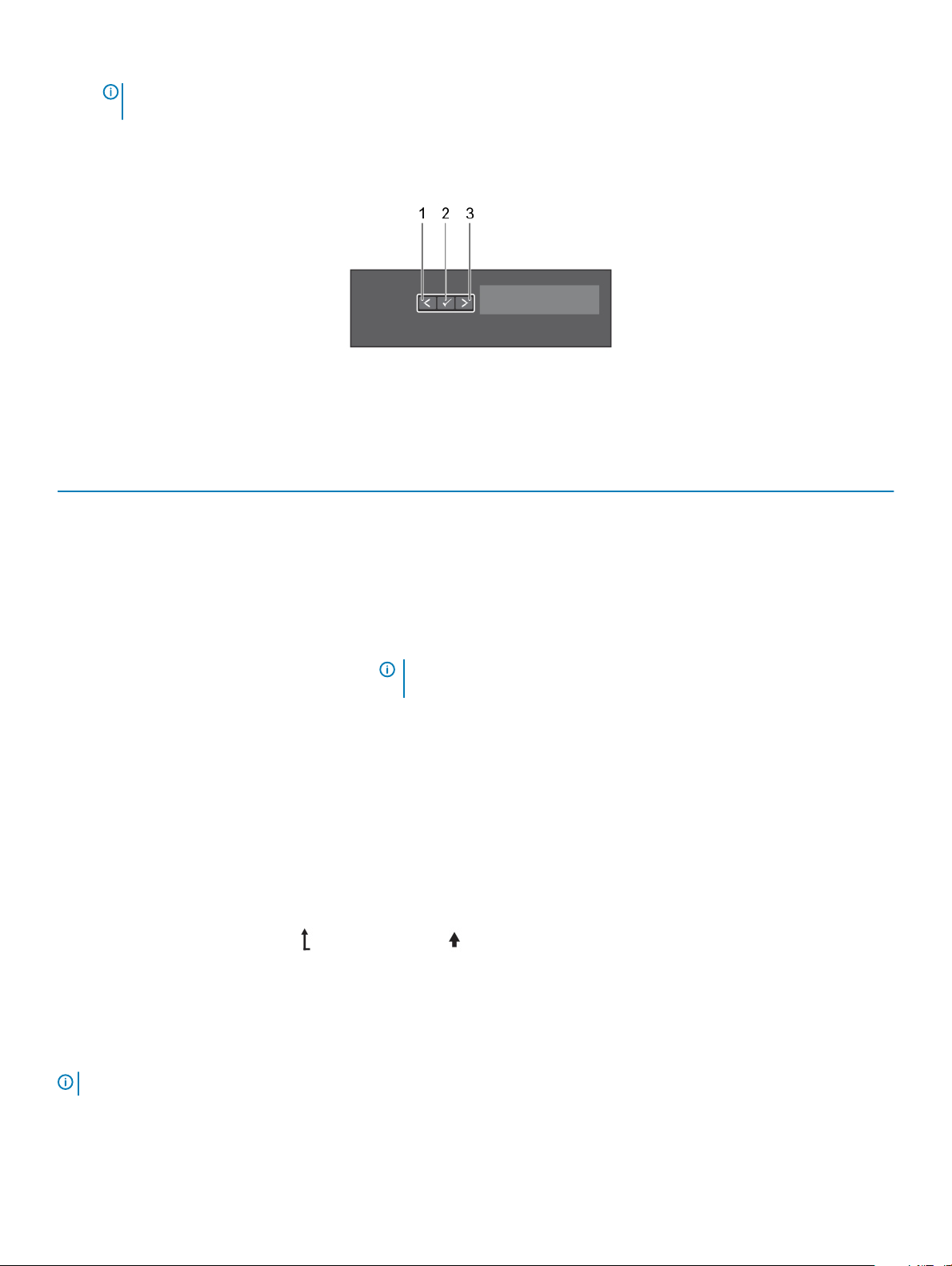
Figure 2. LCD panel features
Table 3. LCD panel features
Item Button Description
1 Left Moves the cursor back in one-step increments.
2 Select Selects the menu item highlighted by the cursor.
3 Right Moves the cursor forward in one-step increments.
During message scrolling:
• Press and hold the button to increase scrolling speed.
• Release the button to stop.
NOTE: The display stops scrolling when the button is released. After 45
seconds of inactivity the display starts scrolling.
Viewing Home screen
About this task
The Home screen displays user-congurable information about the system. This screen is displayed during normal system operation when
there are no status messages or errors. When the system is in standby mode, the LCD backlight turns o after a few minutes of inactivity,
if there are no error messages.
Steps
1 To view the Home screen, press one of the three navigation buttons (Select, Left, or Right).
2 To navigate to the Home screen from another menu, complete the following steps:
a Press and hold the up arrow until the Home icon is displayed.
b Select the Home icon.
c On the Home screen, press the Select button to enter the main menu.
Setup menu
: When you select an option in the Setup menu, you must conrm the option before proceeding to the next action.
NOTE
About your system 9
Option Description
iDRAC Select DHCP or Static IP to congure the network mode. If Static IP is selected, the available elds are IP,
Subnet (Sub), and Gateway (Gtw). Select Setup DNS to enable DNS and to view domain addresses. Two
separate DNS entries are available.
Set error Select SEL to view LCD error messages in a format that matches the IPMI description in the SEL. This enables you
to match an LCD message with an SEL entry.
Select Simple to view LCD error messages in a simplied user-friendly description. For more information about
error messages, see the Dell Event and Error Messages Reference Guide at Dell.com/openmanagemanuals >
OpenManage software.
Set home Select the default information to be displayed on the Home screen. See View menu section for the options and
option items that can be set as the default on the Home screen.
View menu
NOTE: When you select an option in the View menu, you must conrm the option before proceeding to the next action.
Option Description
iDRAC IP Displays the IPv4 or IPv6 addresses for iDRAC8. Addresses include DNS (Primary and Secondary), Gateway, IP,
and Subnet (IPv6 does not have Subnet).
MAC Displays the MAC addresses for iDRAC, iSCSI, or Network devices.
Name Displays the name of the Host, Model, or User String for the system.
Number Displays the Asset tag or the Service tag for the system.
Power Displays the power output of the system in BTU/hr or Watts. The display format can be congured in the Set
home submenu of the Setup menu.
Temperature Displays the temperature of the system in Celsius or Fahrenheit. The display format can be congured in the Set
home submenu of the Setup menu.
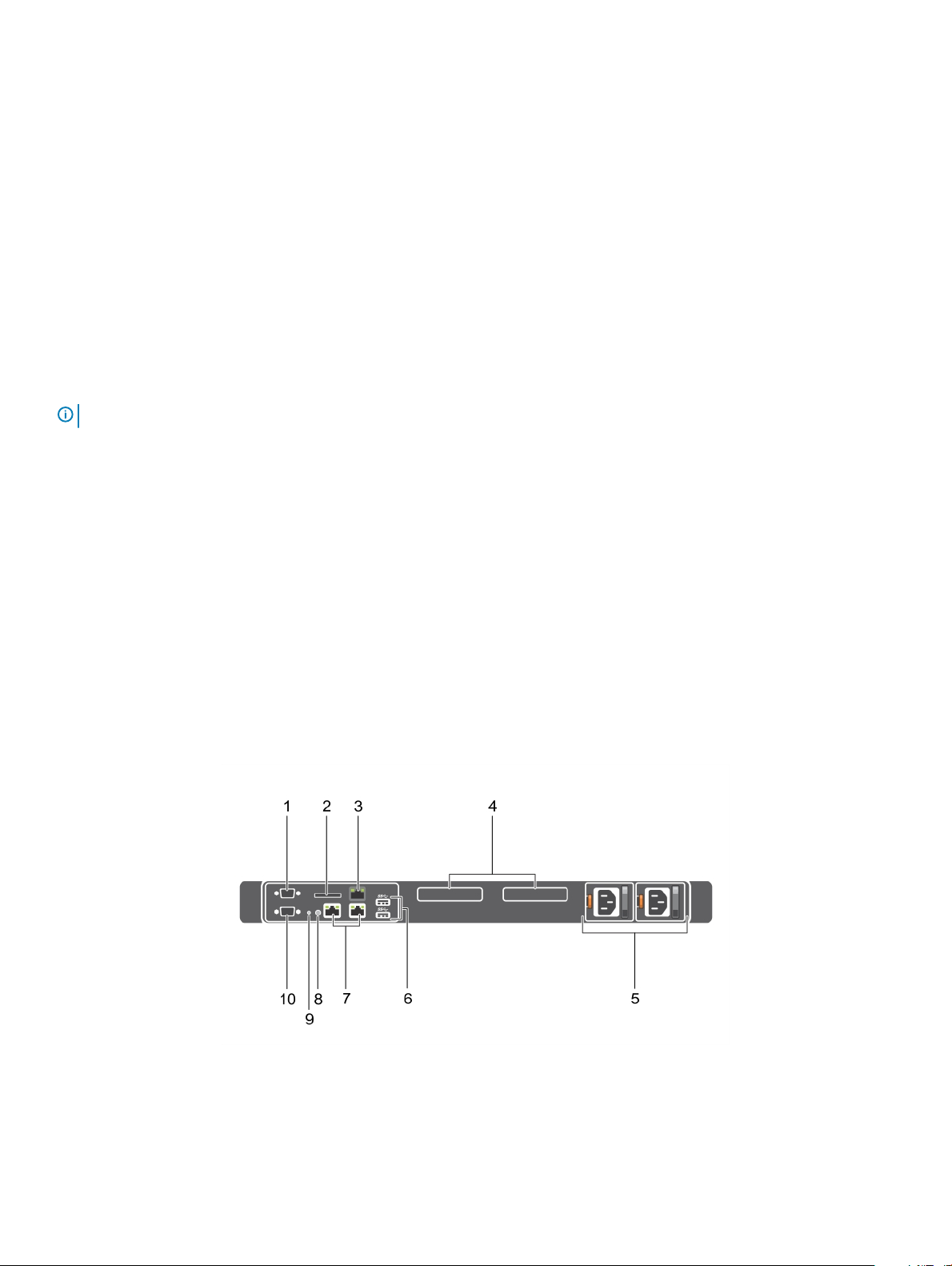
Back panel features and indicators
Figure 3. Back panel features and indicators
About your system
10

Table 4. Back panel features and indicators
Item Indicator, button, or connector Icon Description
1 Serial connector Enables you to connect a serial device to the system.
2 vFlash card slot (optional) Enables you to connect the vFlash card.
3 iDRAC port (optional) Enables you to install a dedicated management port card.
4 PCIe expansion card slots (2) Enables you to connect PCI Express expansion cards.
5 Power supply unit (PSU1 and
PSU2)
6 USB connectors Enables you to connect USB devices to the system. These ports are
7 Ethernet connectors Enables you to connect Integrated 10/100/1000 Mbps NIC
8 System identication button Enables you to locate a particular system within a rack. The
9 System identication connector Connects the optional system status indicator assembly through
Enables you to install up to two 350 W redundant AC power supply
units.
USB 3.0-compliant.
connectors.
identication buttons are on the front and back panels. When one
of these buttons is pressed, the LCD panel on the front and the
system status indicator on the back ash until one of the buttons is
pressed again.
Press the system identication button to turn the system ID on or
o.
If the system stops responding during POST, press and hold the
system ID button for more than ve seconds to enter BIOS
progress mode.
To reset iDRAC (if not disabled in F2 iDRAC setup), press and hold
the button for more than 15 seconds.
the optional cable management arm.
10 Video connector Enables you to connect a VGA display to the system.
About your system 11
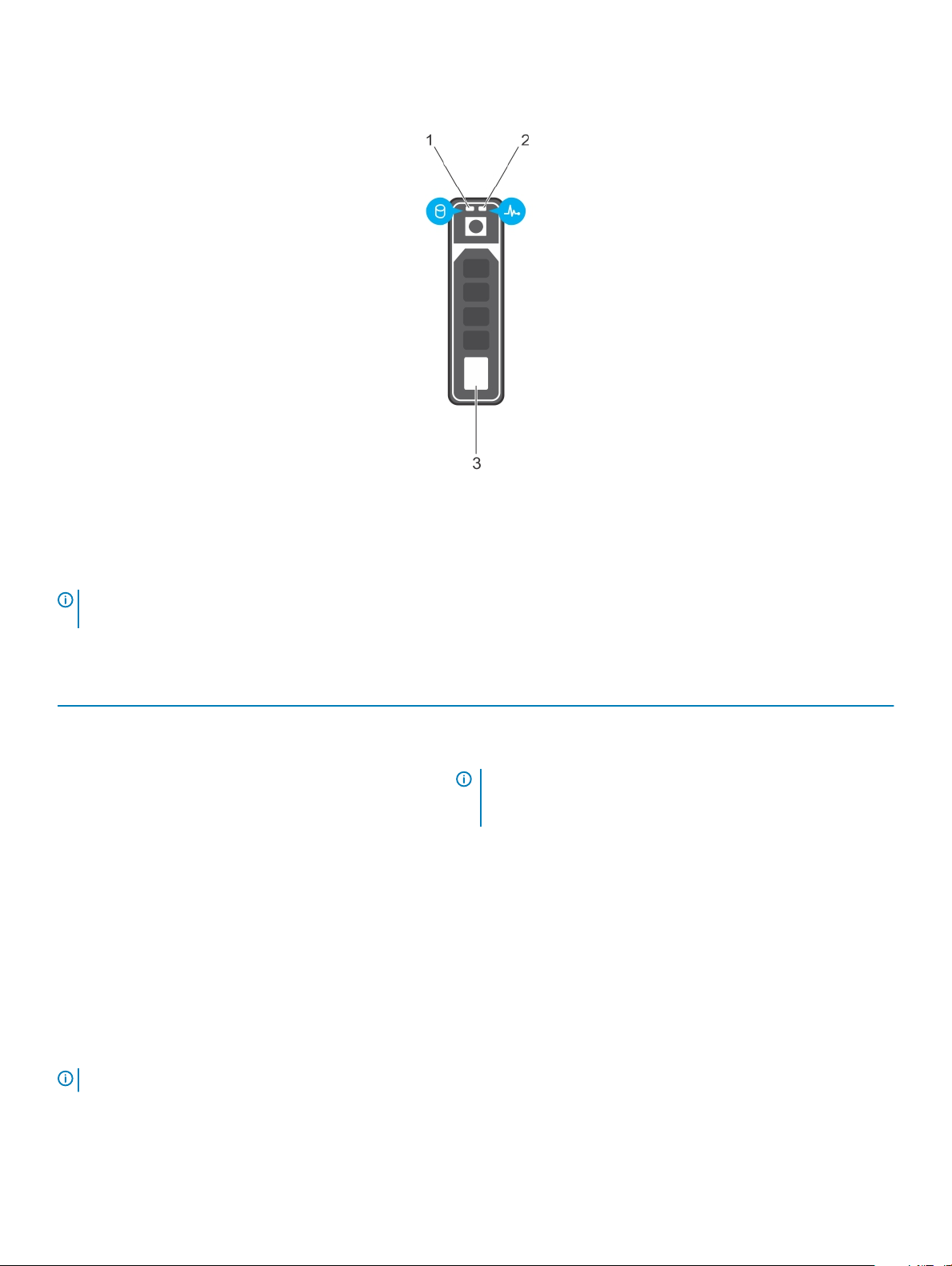
Hot swappable hard drive indicator codes
Figure 4. Hot swappable hard drive indicators
1
hard drive activity indicator 2 hard drive status indicator
3 hard drive
NOTE: If the hard drive is in Advanced Host Controller Interface (AHCI) mode, the status indicator (on the right side) does not
function and remains OFF.
Table 5. Hot swappable hard drive indicators
Drive-status indicator pattern (RAID only) Condition
Flashes green two times per second Identifying drive or preparing for removal.
OFF Drive ready for insertion or removal.
NOTE: The drive status indicator remains OFF until all hard
drives are initialized after the system is turned on. Drives are
not ready for insertion or removal during this time.
Flashes green, amber, and turns o Predicted drive failure
Flashes amber four times per second Drive failed
Flashes green slowly Drive rebuilding
Turns green Drive online
Flashes green three seconds, amber three seconds, and turns
o six seconds
Rebuild stopped
iDRAC Direct LED indicator codes
: The iDRAC Direct LED indicator does not turn on when the USB port is used in the USB mode.
NOTE
12 About your system

Figure 5. iDRAC Direct LED indicator
1 iDRAC Direct status indicator
The iDRAC Direct LED indicator table describes iDRAC Direct activity when conguring iDRAC Direct by using the management port (USB
XML Import).
Table 6. iDRAC Direct LED indicators
Convention iDRAC Direct LED
A Green Turns green for a minimum of two seconds to indicate the start and end of a le transfer.
B Flashing green Indicates le transfer or any operation tasks.
C Green and turns o Indicates that the le transfer is complete.
D Not lit Indicates that the USB is ready to be removed or that a task is complete.
The following table describes iDRAC Direct activity when conguring iDRAC Direct by using your laptop and cable (Laptop Connect):
Table 7. iDRAC Direct LED indicator patterns
iDRAC Direct LED
indicator pattern
Solid green for two seconds Indicates that the laptop is connected.
Flashing green (on for two
seconds and o for two
seconds)
Turns o Indicates that the laptop is unplugged.
indicator pattern
Condition
Indicates that the laptop connected is recognized.
Condition
About your system 13
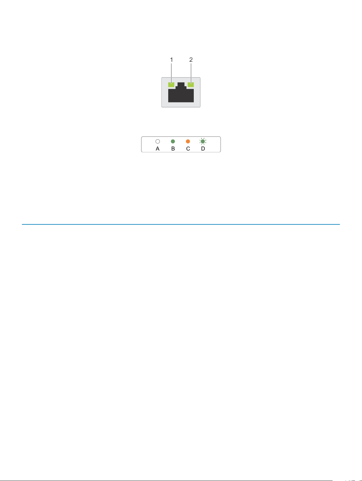
NIC indicator codes
Figure 6. NIC indicators
1 link indicator 2 activity indicator
Table 8. NIC indicators
Convention Indicators Condition
A Link and activity indicators are o The NIC is not connected to the network.
B Link indicator is green
C Link indicator is amber The NIC is connected to a valid network at less than
its maximum port speed.
D Activity indicator is ashing green Network data is being sent or received.
Indicator codes for redundant power supply unit
Each AC power supply unit (PSU) has an illuminated translucent handle that indicates whether power is present or whether a power fault
has occurred.
14
About your system

Figure 7. AC PSU status indicator
1 AC PSU status indicator or handle
Table 9. Redundant AC PSU status indicator
Convention Power Indicator
Pattern
A Green A valid power source is connected to the PSU and the PSU is operational.
B Flashing green When the PSU rmware is being updated, the PSU handle ashes green.
C Flashing green and
turns o
D Flashing amber Indicates a problem in the PSU.
Condition
CAUTION: Do not disconnect the power cord or unplug the PSU when updating
rmware. If rmware update is interrupted, the PSUs will not function. You must
roll back the PSU rmware by using Dell Lifecycle Controller. For more
information, see Dell Lifecycle Controller User’s Guide at Dell.com/idracmanuals.
When hot-adding a PSU, the PSU handle ashes green ve times at 4 Hz rate and turns
o. This indicates that there is a PSU mismatch with respect to eciency, feature set,
health status, and supported voltage. Ensure that both the PSUs are the same.
CAUTION: When correcting a PSU mismatch, replace only the PSU with the
ashing indicator. Swapping the other PSU to make a matched pair can result in
an error condition and unexpected system shutdown. To change from a High
Output conguration to a Low Output conguration or vice versa, you must turn
o the system.
CAUTION: AC PSUs support both 220 V and 110 V input voltages with the
exception of Titanium PSUs, which support only 220 V. When two identical
PSUs receive dierent input voltages, they can output dierent wattages, and
trigger a mismatch.
CAUTION: If two PSUs are used, they must be of the same type and have the
same maximum output power.
CAUTION: Combining AC and DC PSUs is not supported and triggers a
mismatch.
E Not lit Power is not connected.
About your system 15

Locating Service Tag of your system
Your system is identied by a unique Express Service Code and Service Tag number. The Express Service Code and Service Tag are found
on the front of the system by pulling out the information tag. Alternatively, the information may be on a sticker on the chassis of the
system. This information is used by Dell to route support calls to the appropriate personnel.
16 About your system

Documentation resources
This section provides information about the documentation resources for your system.
Task Document Location
2
Setting up your system For information about installing the system into a
rack, see the Rack documentation included with
your rack solution.
For information about turning on the system and
the technical specications of your system, see the
Getting Started With Your System document that
shipped with your system.
For information about procedures for setting up
the storage system and internal storage, see
Setting Up Your Dell Storage NX430 Network
Attached Storage System .
Conguring your system For information about conguring, managing,
updating, and restoring the system, see the Dell
EMC Network Attached Storage System using
Windows Storage Server 2016 Administrator's
Guide.
For information about the iDRAC features,
conguring and logging in to iDRAC, and managing
your system remotely, see the Integrated Dell
Remote Access Controller User's Guide.
For information about understanding Remote
Access Controller Admin (RACADM)
subcommands and supported RACADM interfaces,
see the RACADM Command Line Reference Guide
for iDRAC.
Dell.com/storagemanuals
Dell.com/storagemanuals
Dell.com/idracmanuals
Dell.com/idracmanuals
For information about updating drivers and
rmware.
Troubleshooting your system For information about troubleshooting the
hardware issues, see the Dell EMC Network
Attached Storage Systems using Windows Storage
Server 2016 Troubleshooting Guide.
Managing your system For information about the features of the Dell
OpenManage Systems Management, see the Dell
OpenManage Systems Management Overview
Guide.
For information about setting up, using, and
troubleshooting OpenManage, see the Dell
OpenManage Server Administrator User’s Guide.
Dell.com/support/drivers
Dell.com/storagemanuals
Dell.com/openmanagemanuals
Dell.com/openmanagemanuals
Documentation resources 17

Task Document Location
Working with the Dell EMC
PowerEdge RAID controllers
Understanding event and error
messages
For information about installing, using, and
troubleshooting Dell OpenManage Essentials, see
the Dell OpenManage Essentials User’s Guide.
For information about installing and using Dell
System E-Support Tool (DSET), see the Dell
System E-Support Tool (DSET) User's Guide.
For understanding the features of Dell Lifecycle
Controller, see the Dell Lifecycle Controller User’s
Guide.
For information about enterprise systems
management partner programs, see the
OpenManage Connections Enterprise Systems
Management documents.
For information about connections and client
systems management, see the OpenManage
Connections Client Systems Management
documentation.
For information about understanding the features
of the Dell PowerEdge RAID controllers (PERC)
and deploying the PERC cards, see the Storage
controller documentation.
For information about checking the event and error
messages generated by the system rmware and
agents that monitor system components, see the
Event and Error Message Reference Guide for 14th
Generation Dell EMC PowerEdge Servers.
Dell.com/openmanagemanuals
Dell.com/DSET
Dell.com/idracmanuals
Dell.com/
omconnectionsenterprisesystemsmanagement
Dell.com/dellclientcommandsuitemanuals
Dell.com/storagecontrollermanuals
Dell.com/openmanagemanuals > OpenManage
Software
18 Documentation resources

Dimensions and weight
Physical Dimensions
Height 42.8 mm (1.68 inch)
3
Technical specications
Width with rack
latches
Width without rack
latches
Depth without bezel 610 mm (24 inch)
Maximum weight for
four hard drive
chassis
Empty weight for
four hard drive
chassis
482.38 mm (18.99 inch)
434.15 mm (17.09 inch)
13.8 kg (30.42 lbs)
6.0 kg (13.22 lbs)
Processor specications
Processor
Type One Intel E3-1200 V5 series
Specication
Expansion bus specications
PCI Express
(PCIe)
Generation 3
expansion slots
(with optional
expansion card
risers)
Specication
LP SLOT 1 One half-height, half-length x4 link
FH SLOT 2 One full-height, half-length x8 link
PCI Express
Generation 3
expansion slots
(without
expansion card
risers)
PCIE_G3_X4 One half-height, half-length x4 link for PERC card
Specication
Technical specications 19

PCI Express
Specication
Generation 3
expansion slots
(without
expansion card
risers)
PCIE_G3_X8 One x8 link for riser
Memory specications
Memory Specication
Architecture 1600 MT/s, 1866 MT/s, or 2133 MT/s DDR4 Unbuered DIMMs
Support for advanced ECC or memory optimized operation
Memory module
sockets
Memory module
capacities (UDIMM)
Minimum RAM 4 GB
Maximum RAM 64 GB
Four 288-pin sockets
4 GB (single-rank), 8 GB (single- and dual-rank), 16 GB (single- and dual-rank)
Power specications
Power supply
unit
Power rating per
power supply unit
Heat dissipation 1357.1 BTU/hr
Voltage 100-240 V AC, autoranging, 50/60 Hz
Specication
350 W (Platinum) (100–240 V AC, 50/60 Hz, 4.8 A–2.4 A)
NOTE: Heat dissipation is calculated by using the power supply wattage rating.
NOTE: This system is also designed to be connected to IT power systems with a phase-to-phase voltage
not exceeding 230 V.
Drive specications
Drives
Four hard drive
systems
Optical drive One optional slim SATA DVD-ROM or DVD+/-RW drive.
20 Technical specications
Specication
Up to four 3.5-inch hot swappable SAS, SATA, or Nearline SAS hard drives
NOTE: For more information about PERC, see the Dell PowerEdge RAID Controller (PERC)
documentation at Dell.com/storagecontrollermanuals.

Connectors specications
Back connectors Specication
NIC Two 10/100/1000 Mbps
Serial DB-9 Serial Port connector
USB Two 9-pin, USB 3.0-compliant
Video 15-pin VGA
iDRAC8 One optional 1 GbE Ethernet
External SD vFlash One optional SD vFlash memory card
NOTE: The card slot is available for use only if the iDRAC8 Enterprise license is installed on your system.
Front
Specication
connectors
USB Two 4-pin, USB 2.0-compliant
Video 15-pin VGA
Internal
Specication
connectors
USB One 9-pin, USB 3.0-compliant
Internal Dual SD
Module
Two optional ash memory card slots with the internal SD module
NOTE: One card slot is dedicated for redundancy.
Video specications
Video
Video type Integrated Matrox G200
Video memory 16 MB shared
Specication
Expanded operating temperature
NOTE
: When operating in the expanded temperature range, system performance may be impacted.
NOTE: When operating in the expanded temperature range, ambient temperature warnings may be reported on the LCD and in
the System Event Log.
Expanded
Specications
operating
temperature
≤ 10% of annual
operating hours
5°C to 40°C at 5% to 85% RH with 26°C dew point.
NOTE: Outside the standard operating temperature (10°C to 35°C), the system can operate down to
5°C or up to 40°C for a maximum of 10% of its annual operating hours.
For temperatures between 35°C and 40°C, de-rate maximum allowable dry bulb temperature by 1°C per 175 m
above 950 m (1°F per 319 ft).
Technical specications 21

Expanded
operating
temperature
Specications
≤ 1% of annual
operating hours
Expanded Operating
Temperature
Restrictions
–5°C to 45°C at 5% to 90% RH with 26°C dew point.
NOTE: Outside the standard operating temperature (10°C to 35°C), the system can operate down to –
5°C or up to 45°C for a maximum of 1% of its annual operating hours.
For temperatures between 40°C and 45°C, de-rate maximum allowable dry bulb temperature by 1°C per 125 m
above 950 m (1°F per 228 ft).
• The operating temperature specied is for a maximum altitude of 3048 m (10,000 ft).
• Non-redundant power supply units are not supported.
• Non Dell qualied peripheral cards and/or peripheral cards greater than 25 W are not supported.
• Do not perform a cold startup below 5°C.
• Enable processor performance degrade.
Environmental specications
NOTE: For additional information about environmental measurements for specic system congurations, see Dell.com/
environmental_datasheets.
Temperature Specications
Storage –40°C to 65°C (–40°F to 149°F)
Continuous
operation (for
altitude less than
950 m or 3117 ft)
10°C to 35°C (50°F to 95°F) with no direct sunlight on the equipment.
Fresh air For information on fresh air, see Expanded Operating Temperature section.
Maximum
temperature
gradient (operating
and storage)
20°C/h (36°F/h)
Relative humidity Specications
Storage 5% to 95% RH with 33°C (91°F) maximum dew point. Atmosphere must be non-condensing at all times.
Operating 10% to 80% Relative Humidity with 29°C (84.2°F) maximum dew point.
Maximum
Specications
vibration
Operating 0.26 G
Storage 1.88 G
at 5 Hz to 350 Hz (all operation orientations).
rms
at 10 Hz to 500 Hz for 15 min (all six sides tested).
rms
Maximum shock Specications
Operating Six consecutively executed shock pulses in the positive and negative x, y, and z axes of 40 G for up to 2.3 ms.
Storage Six consecutively executed shock pulses in the positive and negative x, y, and z axes (one pulse on each side of the
system) of 71 G for up to 2 ms.
22 Technical specications

Maximum
altitude
Specications
Operating
Storage 12,000 m (39,370 ft).
Operating
3048 m (10,000 ft).
Specications
temperature derating
Up to 35 °C (95 °F) Maximum temperature is reduced by 1°C/300 m (1°F/547 ft) above 950 m (3,117 ft)
The following section denes the limits to help avoid IT equipment damage and/or failure from particulates and gaseous contamination. If
the levels of particulates or gaseous pollution are beyond the specied limits and cause equipment damage or failure, you may need to
rectify the environmental conditions. Remediation of environmental conditions is the responsibility of the customer.
Particulate
Specications
contamination
Air ltration Data center air ltration as dened by ISO Class 8 per ISO 14644-1 with a 95% upper condence limit.
NOTE: Applies to data center environments only. Air ltration requirements do not apply to IT equipment
designed to be used outside a data center, in environments such as an oce or factory oor.
NOTE: Air entering the data center must have MERV11 or MERV13 ltration.
Conductive dust Air must be free of conductive dust, zinc whiskers, or other conductive particles.
NOTE: Applies to data center and non-data center environments.
Corrosive dust
Gaseous
• Air must be free of corrosive dust.
• Residual dust present in the air must have a deliquescent point less than 60% relative humidity.
NOTE: Applies to data center and non-data center environments.
Specications
contamination
Copper coupon
corrosion rate
Silver coupon
corrosion rate
NOTE: Maximum corrosive contaminant levels measured at ≤50% relative humidity.
<300 Å/month per Class G1 as dened by ANSI/ISA71.04-1985.
<200 Å/month as dened by AHSRAE TC9.9.
Technical specications 23

4
Initial system setup and conguration
Setting up your system
Complete the following steps to set up your system:
1 Unpack the system.
2 Install the system into the rack. For more information about installing the system into the rack, see your system Rack Installation
Placemat
3 Connect the peripherals to the system.
4 Connect the system to its electrical outlet.
5 Turn the system on by pressing the power button or by using iDRAC.
6 Turn on the attached peripherals.
iDRAC conguration
The Integrated Dell Remote Access Controller (iDRAC) is designed to make system administrators more productive and improve the overall
availability of Dell systems. iDRAC alerts administrators to system issues, helps them perform remote system management, and reduces the
need for physical access to the system.
at Dell.com/poweredgemanuals.
Options to set up iDRAC IP address
You must congure the initial network settings based on your network infrastructure to enable the communication to and from iDRAC. You
can set up the IP address by using one of the following interfaces:
Interfaces
iDRAC Settings
utility
Dell Deployment
Toolkit
Dell Lifecycle
Controller
Chassis or Server
LCD panel
You must use the default iDRAC IP address 192.168.0.120 to congure the initial network settings, including setting up DHCP or a static IP
for iDRAC.
: To access iDRAC, ensure that you install the iDRAC port card or connect the network cable to the Ethernet connector 1
NOTE
on the system board.
NOTE: Ensure that you change the default user name and password after setting up the iDRAC IP address.
Document/Section
See Dell Integrated Dell Remote Access Controller User's Guide at Dell.com/idracmanuals
See Dell Deployment Toolkit User’s Guide at Dell.com/openmanagemanuals
See Dell Lifecycle Controller User’s Guide at Dell.com/idracmanuals
See the LCD panel section
24 Initial system setup and conguration

Log in to iDRAC
You can log in to iDRAC as:
• iDRAC user
• Microsoft Active Directory user
• Lightweight Directory Access Protocol (LDAP) user
The default user name and password are root and calvin. You can also log in by using Single Sign-On or Smart Card.
NOTE: You must have iDRAC credentials to log in to iDRAC.
For more information about logging in to iDRAC and iDRAC licenses, see the Integrated Dell Remote Access Controller User's Guide at
Dell.com/idracmanuals.
Reinstalling the NAS operating system by using DVD
About this task
CAUTION: Back up the internal disk drives on your system before reinstalling or upgrading the NAS Operating System. The DVD
reinstall process formats or deletes the OS disks (virtual disk 0) resulting in loss of any data or installed applications. The DVD
reinstall process does not install RASR USB Recovery application.
Steps
1 Back up data that is stored on any internal disk drives or external storage arrays.
2 If required, connect the external USB DVD drive to your NAS system.
3 Insert your Dell Storage NAS Operating System resource media into your NAS system.
4 Restart your NAS system and ensure that your NAS system boots from the resource media.
The OS reinstallation begins and proceeds without any user intervention, if no errors are encountered. This process takes around 60 to
90 minutes to complete. Errors encountered are also agged on the front panel LCD of your device. To resolve issues, see the Dell
Storage Network Attached Storage (NAS) Systems Troubleshooting Guide available at Dell.com/storagemanuals.
5 After reinstalling the OS, complete the initial conguration tasks.
NOTE
: For information about the initial conguration tasks, see the Initial conguration of your NAS system section in
Dell Storage Network Attached Storage (NAS) Systems Running Windows Storage Server 2016 or 2012 R2
Administrator's Guide
.
Initial system setup and conguration 25

Pre-operating system management applications
You can manage basic settings and features of a system without booting to the operating system by using the system rmware.
Options to manage the pre-operating system applications
Your system has the following options to manage the pre-operating system applications:
• System Setup
• Dell Lifecycle Controller
• Boot Manager
• Preboot Execution Environment (PXE)
NOTE: The NX430 system does not support UEFI mode.
System Setup
5
By using the System Setup screen, you can congure the BIOS settings, iDRAC settings, and device settings of your system.
: Help text for the selected eld is displayed in the graphical browser by default. To view the help text in the text browser,
NOTE
press F1.
You can access system setup by using two methods:
• Standard graphical browser—The browser is enabled by default.
• Text browser—The browser is enabled by using Console Redirection.
Viewing System Setup
To view the System Setup screen, perform the following steps:
1 Turn on, or restart your system.
2 Press F2 immediately after you see the following message:
F2 = System Setup
NOTE
: If your operating system begins to load before you press F2, wait for the system to nish booting, and then
restart your system and try again.
System Setup details
The System Setup Main Menu screen provides the following options.
: The NX Series systems support only BIOS mode. Do not change the boot mode to UEFI because the system will not load
NOTE
the appliance OS when in UEFI mode.
26 Pre-operating system management applications

Option Description
System BIOS Enables you to congure BIOS settings.
iDRAC Settings Enables you to congure the iDRAC settings.
The iDRAC settings utility is used to set up and congure the iDRAC parameters. You can enable or disable various
iDRAC parameters using the iDRAC settings utility. For more information about this utility, see Integrated Dell
Remote Access Controller User’s Guide at Dell.com/idracmanuals.
Device Settings Enables you to congure device settings.
System BIOS
You can use the System BIOS screen to edit specic functions such as boot order, system password, setup password, set the RAID mode,
and enable or disable USB ports.
Viewing System BIOS
To view the System BIOS screen, perform the following steps:
1 Turn on, or restart your system.
2 Press F2 immediately after you see the following message:
F2 = System Setup
NOTE
: If your operating system begins to load before you press F2, wait for the system to nish booting, and then
restart your system and try again.
3 On the System Setup Main Menu screen, click System BIOS.
System BIOS Settings details
The System BIOS Settings screen provides the following options.
: The NX Series systems support only BIOS mode. Do not change the boot mode to UEFI because the system will not load
NOTE
the appliance OS when in UEFI mode.
Option Description
System Information Species information about the system such as the system model name, BIOS version, and Service Tag.
Memory Settings Species information and options related to the installed memory.
Processor Settings Species information and options related to the processor such as speed and cache size.
SATA Settings Species options to enable or disable the integrated SATA controller and ports.
Boot Settings Species options to choose the Boot mode and allows you to modify the boot settings.
Network Settings Species options to manage the network settings and boot protocols.
Legacy network settings are managed from the Device Settings menu.
Integrated Devices Species options to manage integrated device controllers and ports, species related features and options.
Serial
Communication
System Prole
Settings
Species options to manage the serial ports, its related features and options.
Species options to change the processor power management settings, memory frequency.
Pre-operating system management applications 27

Option Description
System Security Species options to congure the system security settings, such as system password, setup password, and
Trusted Platform Module (TPM) security. This option also manages the power button on the system.
Miscellaneous
Settings
Species options to change the system date and time.
Boot Settings
You can use the Boot Settings screen to set the boot mode to either BIOS. It also enables you to specify the boot order.
Viewing Boot Settings
To view the Boot Settings screen, perform the following steps:
1 Turn on, or restart your system.
2 Press F2 immediately after you see the following message:
F2 = System Setup
NOTE: If your operating system begins to load before you press F2, wait for the system to nish booting, and then
restart your system and try again.
3 On the System Setup Main Menu screen, click System BIOS.
4 On the System BIOS screen, click Boot Settings.
Boot Settings details
The Boot Settings screen details are explained as follows:
Option
Boot Mode Enables you to set the boot mode of the system.
Boot Sequence
Retry
Hard-Disk Failover Species the drive that is booted in the event of a drive failure. The devices are selected in the Hard-Disk Drive
Boot Option
Settings
BIOS Boot Settings Enables or disables BIOS boot options.
Description
CAUTION: Switching the boot mode may prevent the system from booting if the operating system is not
installed in the same boot mode.
Enables or disables the Boot Sequence Retry feature. If this option is set to Enabled and the system fails to boot,
the system re-attempts the boot sequence after 30 seconds. This option is set to Enabled by default.
Sequence on the Boot Option Setting menu. When this option is set to Disabled, only the rst drive in the list is
attempted to boot. When this option is set to Enabled, all drives are attempted to boot in the order selected in the
Hard-Disk Drive Sequence. This option is set to Disabled by default.
Congures the boot sequence and the boot devices.
NOTE: This option is enabled only if the boot mode is BIOS.
Choosing the system boot mode
System Setup enables you to specify one of the following boot modes for installing your operating system:
About this task
• BIOS boot mode (the default) is the standard BIOS-level boot interface.
• Unied Extensible Firmware Interface (UEFI) boot mode is an enhanced 64-bit boot interface. If you have congured your system to
boot to UEFI mode, it overlays the system BIOS.
Pre-operating system management applications
28

NOTE: The NX Series systems support only BIOS mode. Do not change the boot mode to UEFI because the system will not load
the appliance OS when in UEFI mode.
Steps
1 From the System Setup Main Menu, click Boot Settings, and select Boot Mode.
2 Select the boot mode you want the system to boot into.
CAUTION: Switching the boot mode may prevent the system from booting if the operating system is not installed in the
same boot mode.
After the system boots in the specied boot mode, proceed to install your operating system from that mode.
3
NOTE: Operating systems must be UEFI-compatible to be installed from the UEFI boot mode. DOS and 32-bit operating systems
do not support UEFI and can only be installed from the BIOS boot mode.
NOTE: For the latest information about supported operating systems, go to Dell.com/ossupport.
Changing the boot order
You may have to change the boot order if you want to boot from a USB key or an optical drive. The following instructions may vary if you
have selected BIOS for Boot Mode.
1 On the System Setup Main Menu screen, click System BIOS > Boot Settings.
2 Click Boot Option Settings > Boot Sequence.
3 Use the arrow keys to select a boot device, and use the plus (+) and minus (-) sign keys to move the device down or up in the order.
4 Click Exit, and then click Yes to save the settings on exit.
System Security
You can use the System Security screen to perform specic functions such as setting the system password, setup password and disabling
the power button.
Viewing System Security
To view the System Security screen, perform the following steps:
1 Turn on, or restart your system.
2 Press F2 immediately after you see the following message:
F2 = System Setup
NOTE
: If your operating system begins to load before you press F2, wait for the system to nish booting, and then
restart your system and try again.
3 On the System Setup Main Menu screen, click System BIOS.
4 On the System BIOS screen, click System Security.
System Security Settings details
The System Security Settings screen provides the following options:
Option
Intel AES-NI Improves the speed of applications by performing encryption and decryption by using the Advanced Encryption
Description
Standard Instruction Set (AES-NI). This option is set to Enabled by default.
System Password Sets the system password. This option is set to Enabled by default and is read-only if the password jumper is not
installed in the system.
Setup Password Sets the setup password. This option is read-only if the password jumper is not installed in the system.
Password Status Locks the system password. This option is set to Unlocked by default.
Pre-operating system management applications 29

Option Description
TPM Security
TPM Information Changes the operational state of the TPM. This option is set to No Change by default.
TPM Status Species the TPM status.
TPM Command
Intel TXT Enables or disables the Intel Trusted Execution Technology (TXT) option. To enable the Intel TXT option,
Power Button Enables or disables the power button on the front of the system. This option is set to Enabled by default.
NMI Button Enables or disables the NMI button on the front of the system. This option is set to Disabled by default.
AC Power Recovery Sets how the system behaves after AC power is restored to the system. This option is set to Last by default.
AC Power Recovery
Delay
User Dened Delay
(60s to 240s)
NOTE: The TPM menu is available only when the TPM module is installed.
Enables you to control the reporting mode of the TPM. The TPM Security option is set to O by default. You can
only modify the TPM Status, TPM Activation, and Intel TXT elds if the TPM Status eld is set to either On with
Pre-boot Measurements or On without Pre-boot Measurements.
CAUTION: Clearing the TPM results in the loss of all keys in the TPM. The loss of TPM keys may aect
booting to the operating system.
Clears all the contents of the TPM. The TPM Clear option is set to No by default.
virtualization technology and TPM Security must be enabled with Pre-boot measurements. This option is set to O
by default.
Sets the time delay for the system to power up after AC power is restored to the system. This option is set to
Immediate by default.
Sets the User Dened Delay option when the User Dened option for AC Power Recovery Delay is selected.
UEFI Variable
Access
Secure Boot Enables Secure Boot, where the BIOS authenticates each pre-boot image by using the certicates in the Secure
Secure Boot Policy When Secure Boot policy is set to Standard, the BIOS uses the system manufacturer’s key and certicates to
Secure Boot Policy
Summary
NOTE: The NX430 system does not support UEFI mode. This option cannot be used.
Provides varying degrees of securing UEFI variables. When set to Standard (the default), UEFI variables are
accessible in the operating system per the UEFI specication. When set to Controlled, selected UEFI variables are
protected in the environment and new UEFI boot entries are forced to be at the end of the current boot order.
Boot Policy. Secure Boot is disabled by default.
authenticate pre-boot images. When Secure Boot policy is set to Custom, the BIOS uses the user-dened key and
certicates. Secure Boot policy is set to Standard by default.
Species the list of certicates and hashes that secure boot uses to authenticate images.
Secure Boot Custom Policy Settings
Secure Boot Custom Policy Settings is displayed only when Secure Boot Policy is set to Custom.
Viewing Secure Boot Custom Policy Settings
To view the Secure Boot Custom Policy Settings screen, perform the following steps:
1 Turn on, or restart your system.
2 Press F2 immediately after you see the following message:
F2 = System Setup
: If your operating system begins to load before you press F2, wait for the system to nish booting, and then
NOTE
restart your system and try again.
30 Pre-operating system management applications
 Loading...