

Dell Storage NX3230 User Manual

Dell Storage NX3230 Systems
Owner's Manual
July 2020
Rev. A02

Notes, cautions, and warnings
NOTE: A NOTE indicates important information that helps you make better use of your product.
CAUTION: A CAUTION indicates either potential damage to hardware or loss of data and tells you how to avoid the
problem.
WARNING: A WARNING indicates a potential for property damage, personal injury, or death.
© 2017 - 2020 Dell Inc. or its subsidiaries. All rights reserved. Dell, EMC, and other trademarks are trademarks of Dell Inc. or its subsidiaries. Other
trademarks may be trademarks of their respective owners.

Contents
Chapter 1: About your system.......................................................................................................... 7
Back-panel features and indicators..................................................................................................................................... 7
Front-panel features and indicators....................................................................................................................................8
Diagnostic indicators on the front panel.............................................................................................................................9
Drive indicator codes............................................................................................................................................................11
iDRAC Direct LED indicator codes......................................................................................................................................11
NIC indicator codes..............................................................................................................................................................13
Power supply unit indicator codes..................................................................................................................................... 13
Locating Service Tag of your system................................................................................................................................15
Chapter 2: Documentation resources.............................................................................................. 16
Chapter 3: Technical specifications.................................................................................................18
Chapter 4: Initial system setup and configuration............................................................................ 23
Setting up your system.......................................................................................................................................................23
Options to set up iDRAC IP address................................................................................................................................. 23
Log in to iDRAC................................................................................................................................................................... 23
Managing your system remotely....................................................................................................................................... 24
Methods to download firmware and drivers....................................................................................................................24
Chapter 5: Pre-operating system management applications............................................................. 25
Options to manage the pre-operating system applications...........................................................................................25
System Setup.......................................................................................................................................................................25
Viewing System Setup..................................................................................................................................................25
System Setup details.....................................................................................................................................................26
System BIOS.................................................................................................................................................................. 26
iDRAC Settings utility....................................................................................................................................................43
Device Settings..............................................................................................................................................................44
Dell Lifecycle Controller...................................................................................................................................................... 44
Embedded systems management............................................................................................................................... 44
Boot Manager...................................................................................................................................................................... 44
Viewing Boot Manager..................................................................................................................................................44
Boot Manager main menu............................................................................................................................................ 44
PXE boot.............................................................................................................................................................................. 45
Chapter 6: Installing and removing system components................................................................... 46
Safety instructions.............................................................................................................................................................. 46
Before working inside your system....................................................................................................................................47
After working inside your system...................................................................................................................................... 47
Recommended tools............................................................................................................................................................47
Front bezel (optional)..........................................................................................................................................................47
Removing the front bezel............................................................................................................................................. 47
Installing the optional front bezel.................................................................................................................................48
Contents 3

Removing the system cover.............................................................................................................................................. 48
Installing the system cover.................................................................................................................................................49
Inside the system.................................................................................................................................................................49
Cooling shroud.....................................................................................................................................................................50
Removing the cooling shroud...................................................................................................................................... 50
Installing the cooling shroud..........................................................................................................................................51
System memory...................................................................................................................................................................52
General memory module installation guidelines......................................................................................................... 52
Mode-specific guidelines.............................................................................................................................................. 53
Sample memory configurations................................................................................................................................... 53
Removing memory modules.........................................................................................................................................55
Installing memory modules........................................................................................................................................... 56
Hard drives...........................................................................................................................................................................58
Removing a 3.5-inch hard drive blank........................................................................................................................ 58
Installing a 3.5-inch hard drive blank...........................................................................................................................59
Removing a 2.5 inch hard drive blank (rear)..............................................................................................................60
Installing a 2.5 inch hard drive blank (rear)................................................................................................................ 60
Removing a hot swappable hard drive or solid state drive....................................................................................... 61
Installing a hot swappable hard drive.......................................................................................................................... 62
Removing hard drive from hard-drive carrier............................................................................................................ 63
Installing hard drive into hard-drive carrier.................................................................................................................64
Cooling fans......................................................................................................................................................................... 65
Removing a cooling fan.................................................................................................................................................65
Installing a cooling fan...................................................................................................................................................66
Cooling fan assembly ......................................................................................................................................................... 67
Removing the cooling fan assembly............................................................................................................................67
Installing the cooling fan assembly.............................................................................................................................. 68
Expansion cards and expansion card riser........................................................................................................................69
Expansion card installation guidelines..........................................................................................................................70
Removing an expansion card from expansion card riser 2 or 3................................................................................71
Installing an expansion card into the expansion card riser 2 or 3............................................................................ 73
Removing an expansion card from the expansion card riser 1.................................................................................74
Installing an expansion card into the expansion card riser 1.....................................................................................75
Removing the riser 1 blank............................................................................................................................................76
Installing the riser 1 blank...............................................................................................................................................77
Removing expansion card risers...................................................................................................................................77
Installing expansion card risers.....................................................................................................................................82
SD vFlash card (optional)...................................................................................................................................................82
Removing the optional SD vFlash card.......................................................................................................................82
Removing the vFlash media unit..................................................................................................................................83
Installing the vFlash media unit.................................................................................................................................... 84
Integrated storage controller card.................................................................................................................................... 85
Removing integrated storage controller card............................................................................................................ 85
Installing integrated storage controller card...............................................................................................................86
Network daughter card.......................................................................................................................................................87
Removing the network daughter card .......................................................................................................................87
Installing the network daughter card.......................................................................................................................... 88
Processors and heat sinks..................................................................................................................................................90
Removing a processor.................................................................................................................................................. 90
Installing a processor.....................................................................................................................................................92
4
Contents

PCIe card holder..................................................................................................................................................................94
Removing the PCIe card holder...................................................................................................................................95
Installing PCIe card holder............................................................................................................................................95
Opening and closing the PCIe card holder latch....................................................................................................... 96
Cable retention bracket...................................................................................................................................................... 97
Removing the cable retention bracket........................................................................................................................97
Installing the cable retention bracket..........................................................................................................................98
Power supply units..............................................................................................................................................................99
Hot spare feature.......................................................................................................................................................... 99
Removing the power supply unit blank.......................................................................................................................99
Installing the power supply unit blank........................................................................................................................100
Removing an AC power supply unit............................................................................................................................101
Installing an AC power supply unit............................................................................................................................. 102
Wiring instructions for a DC power supply unit........................................................................................................103
Removing a DC power supply unit.............................................................................................................................104
Installing a DC power supply unit............................................................................................................................... 105
System battery...................................................................................................................................................................106
Replacing system battery........................................................................................................................................... 106
Hard disk drive backplane................................................................................................................................................. 107
Removing HDD backplane...........................................................................................................................................107
Installing HDD backplane..............................................................................................................................................110
Removing the optional HDD backplane (back)..........................................................................................................111
Installing the optional HDD backplane (back)........................................................................................................... 112
Control panel....................................................................................................................................................................... 113
Removing the control panel ........................................................................................................................................113
Installing the control panel ..........................................................................................................................................114
Removing the I/O panel ..............................................................................................................................................115
Installing the I/O panel................................................................................................................................................. 116
System board...................................................................................................................................................................... 117
Removing system board...............................................................................................................................................117
Installing system board................................................................................................................................................ 120
Trusted Platform Module...................................................................................................................................................121
Installing the Trusted Platform Module.....................................................................................................................122
Initializing the TPM for BitLocker users.................................................................................................................... 123
Initializing the TPM for TXT users..............................................................................................................................123
Chapter 7: Using system diagnostics............................................................................................. 124
Dell Embedded System Diagnostics................................................................................................................................ 124
When to use the Embedded System Diagnostics....................................................................................................124
Running the Embedded System Diagnostics from Boot Manager........................................................................ 124
Running the Embedded System Diagnostics from the Dell Lifecycle Controller................................................. 124
System diagnostic controls.........................................................................................................................................125
Chapter 8: Jumpers and connectors ............................................................................................. 126
System board jumper settings..........................................................................................................................................126
System board connectors.................................................................................................................................................127
Disabling forgotten password...........................................................................................................................................128
Chapter 9: Troubleshooting your system....................................................................................... 130
Contents
5

Troubleshooting system startup failure...........................................................................................................................130
Troubleshooting external connections............................................................................................................................ 130
Troubleshooting the video subsystem............................................................................................................................. 131
Troubleshooting a USB device..........................................................................................................................................131
Troubleshooting iDRAC Direct (USB XML configuration)............................................................................................132
Troubleshooting iDRAC Direct (Laptop connection).................................................................................................... 132
Troubleshooting a serial I/O device.................................................................................................................................133
Troubleshooting a NIC.......................................................................................................................................................133
Troubleshooting a wet system......................................................................................................................................... 133
Troubleshooting a damaged system................................................................................................................................134
Troubleshooting the system battery............................................................................................................................... 135
Troubleshooting power supply units................................................................................................................................135
Troubleshooting power source problems..................................................................................................................136
Power supply unit problems........................................................................................................................................136
Troubleshooting cooling problems................................................................................................................................... 136
Troubleshooting cooling fans............................................................................................................................................137
Troubleshooting system memory.....................................................................................................................................137
Troubleshooting an internal USB key.............................................................................................................................. 138
Troubleshooting an SD card............................................................................................................................................. 139
Troubleshooting a hard drive or SSD.............................................................................................................................. 139
Troubleshooting a storage controller...............................................................................................................................140
Troubleshooting expansion cards..................................................................................................................................... 141
Troubleshooting processors.............................................................................................................................................. 141
System messages.............................................................................................................................................................. 142
Warning messages....................................................................................................................................................... 142
Diagnostic messages....................................................................................................................................................142
Alert messages............................................................................................................................................................. 142
Chapter 10: Getting help.............................................................................................................. 143
Contacting Dell...................................................................................................................................................................143
Documentation feedback..................................................................................................................................................143
Quick Resource Locator ...................................................................................................................................................143
6
Contents
1
About your system
The Dell Storage NX3230 is a rack system that supports up to two processors based on the Intel Haswell E5-2600 v3 processor family, up
to 24 DIMMs, and storage capacity up to 12 internal, hot-swappable 3.5-inch hard disk drives (HDDs) or solid state drives (SSDs).
Topics:
• Back-panel features and indicators
• Front-panel features and indicators
• Diagnostic indicators on the front panel
• Drive indicator codes
• iDRAC Direct LED indicator codes
• NIC indicator codes
• Power supply unit indicator codes
• Locating Service Tag of your system
Back-panel features and indicators
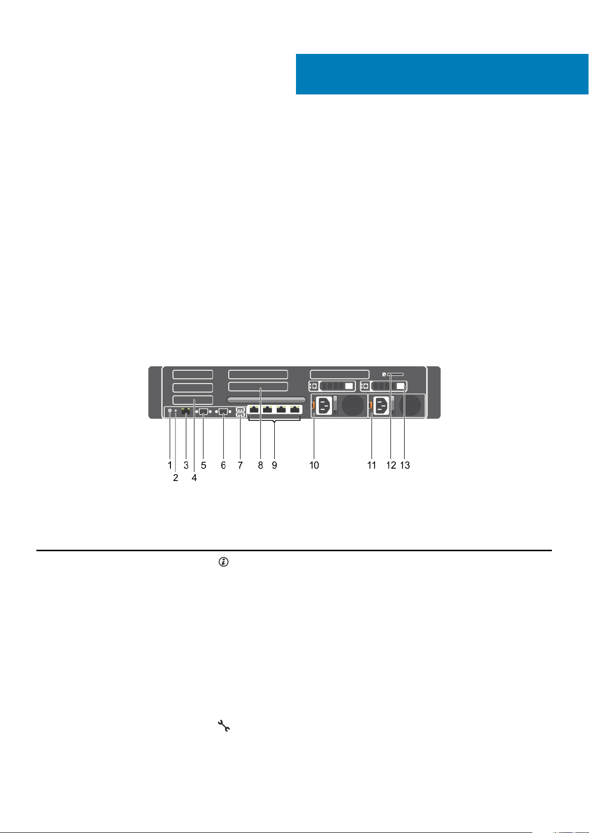
Figure 1. Back-panel features and indicators
Table 1. Back-panel features and indicators
Item Indicator, button, or connector Icon Description
1 System identification button The identification buttons on the front and back panels can be used
to locate a particular system within a rack.
When one of these buttons is pressed, the system status indicator
on the back flashes until one of the buttons is pressed again.
Press to toggle the system ID on and off.
If the system stops responding during POST, press and hold the
system ID button for more than five seconds to enter BIOS progress
mode.
To reset iDRAC (if not disabled in F2 iDRAC setup), press and hold
the button for more than 15 seconds.
2 System identification connector Connects the optional system status indicator assembly through the
optional cable management arm.
3 iDRAC8 Enterprise port Dedicated management port.
About your system 7
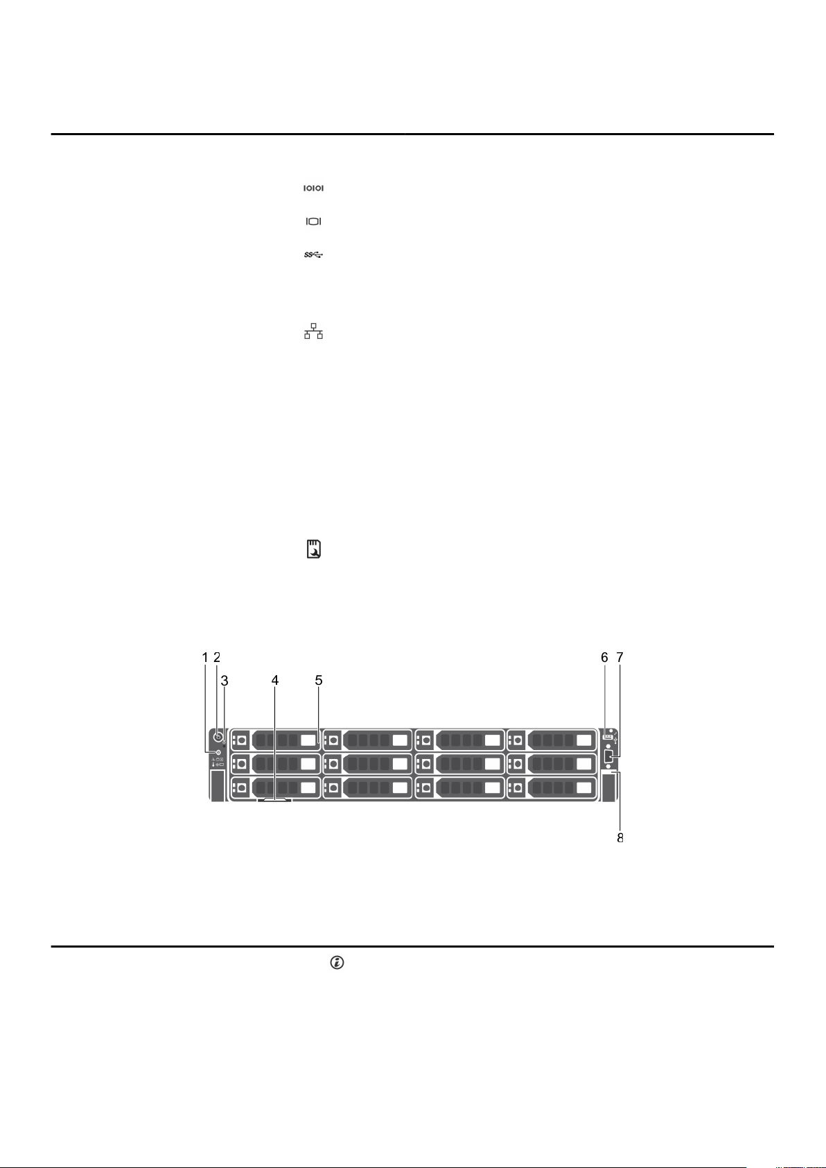
Table 1. Back-panel features and indicators (continued)
Item Indicator, button, or connector Icon Description
4 Half-height PCIe expansion-card
slot (3)
5 Serial connector Allows you to connect a serial device to the system.
6 Video connector Allows you to connect a VGA display to the system.
7 USB connector (2) Allows you to connect USB drives to the system. The ports are USB
8 Full-height PCIe expansion-card slot
(3)
9 Ethernet connector (4) Four integrated 10/100/1000 Mbps NIC connectors
10 Power supply unit (PSU1)
11 Power supply unit (PSU2)
12 vFlash media card slot Allows you to insert a vFlash media card.
Allows you to connect up to three half-height PCI Express expansion
cards.
3.0-compliant.
Allows you to connect up to three full-height PCI Express expansion
cards.
Or
Four integrated connectors that include:
• Two 10/100/1000 Mbps NIC connectors
• Two 100 Mbps/1 Gbps/10 Gbps SFP+/10 GbE T connectors
AC 750 W, or 1100 W
Or
DC 750 W or 1100 W
13 HDD (2) (back) Up to two hot-swappable 2.5-inch HDDs.
Front-panel features and indicators
Figure 2. Front-panel features and indicators (twelve 3.5-inch HDD chassis)
Table 2. Front-panel features and indicators
Item Indicator, Button, or
Connector
1 System identification button The identification buttons on the front and back panels can be
Icon Description
used to locate a particular system within a rack. When one of these
buttons is pressed, the system status indicator on the back flashes
until one of the buttons is pressed again.
Press to toggle the system ID on and off.
8 About your system

Table 2. Front-panel features and indicators (continued)
Item Indicator, Button, or
Connector
Icon Description
If the system stops responding during POST, press and hold the
system ID button for more than five seconds to enter BIOS
progress mode.
To reset the iDRAC (if not disabled in F2 iDRAC setup), press and
hold the button for more than 15 seconds.
2 Power-on indicator, power
button
3 NMI button Used to troubleshoot software and device driver errors when
4 Information tag A slide-out label panel which allows you to record system
5 HDDs Up to twelve 3.5-inch hot-swappable HDDs.
6 USB management port/iDRAC
Direct
The power-on indicator glows when the system power is on. The
power button controls the power supply output to the system.
NOTE: On ACPI-compliant operating systems, turning
off the system using the power button causes the
system to perform a graceful shutdown before power to
the system is turned off.
running certain operating systems. This button can be pressed
using the end of a paper clip.
Use this button only if directed to do so by qualified support
personnel or by the operating system's documentation.
information such as Service Tag, NIC, MAC address, and so on as
per your need.
Allows you to connect USB devices to the system or provides
access to the iDRAC Direct features. For more information, see the
Integrated Dell Remote Access Controller User’s Guide at
Dell.com/esmmanuals. The USB management port is USB 2.0compliant.
NOTE: If the system is connected to a power source and
an issue is detected, the LCD glows amber regardless of
whether the system is turned on or turned off.
7 Video connector Allows you to connect a VGA display to the system.
8 Quick Sync (optional)
NOTE: By default, the Quick Sync option is not available
for the Dell Storage NX3230 system.
Indicates a Quick Sync enabled system. The Quick Sync feature is
optional and requires a Quick Sync bezel. This feature allows
management of the system using mobile devices. This feature
aggregates hardware/firmware inventory and various system level
diagnostic/error information that can be used in troubleshooting
the system. For more information, see the Integrated Dell Remote
Access Controller User’s Guide at Dell.com/esmmanuals.
Diagnostic indicators on the front panel
NOTE: The diagnostic indicators are not present if the system is equipped with an LCD display.
NOTE: No diagnostic indicators are lit when the system is turned off. To start the system, plug it into a working power
source and press the power button.
About your system 9

Table 3. Diagnostic indicators
Icon Description Condition Corrective action
Health indicator The indicator turns solid blue if the
system is in good health.
The indicator flashes amber:
• When the system is turned on.
• When the system is in standby.
• If any error condition exists. For
example, a failed fan, PSU, or a
hard drive.
Hard drive
indicator
Electrical indicator The indicator flashes amber if the
Temperature
indicator
Memory indicator The indicator flashes amber if a
The indicator flashes amber if there is
a hard drive error.
system experiences an electrical error
(for example, voltage out of range, or
a failed power supply unit (PSU) or
voltage regulator).
The indicator flashes amber if the
system experiences a thermal error
(for example, the ambient
temperature is out of range or fan
failure).
memory error occurs.
None required.
Check the System Event Log or system messages for
the specific issue. For more information about error
messages, see the Dell Event and Error Messages
Reference Guide at Dell.com/openmanagemanuals >
OpenManage software.
The POST process is interrupted without any video
output due to invalid memory configurations. See the
Getting help section.
Check the System Event Log to determine the hard drive
that has an error. Run the appropriate Online Diagnostics
test. Restart the system and run embedded diagnostics
(ePSA). If the hard drives are configured in a RAID array,
restart the system and enter the host adapter
configuration utility program.
Check the System Event Log or system messages for
the specific issue. If it is due to a problem with the PSU,
check the LED on the PSU. Reseat the PSU. If the
problem persists, see the Getting help section.
Ensure that none of the following conditions exist:
• A cooling fan has been removed or has failed.
• System cover, cooling shroud, EMI filler panel,
memory module blank, or back filler bracket is
removed.
• Ambient temperature is too high.
• External airflow is obstructed.
See the Getting help section.
Check the system event log or system messages for the
location of the failed memory. Reseat the memory
module. If the problem persists, see the Getting help
section.
10 About your system

Drive indicator codes
Each drive carrier has an activity LED indicator and a status LED indicator. The indicators provide information about the current status of
the drive. The activity LED indicator indicates whether the drive is currently in use or not. The status LED indicator indicates the power
condition of the drive.
Figure 3. Hard drive indicators
1. hard drive activity indicator
2. hard drive status indicator
3. hard drive
Drive status indicator code
Flashes green twice per second Identifying drive or preparing for removal
Off Drive ready for removal
Flashes green, amber, and then turns off Predicted drive failure
Flashes amber four times per second Drive failed
Flashes green slowly Drive rebuilding
Solid green Drive online
Flashes green for three seconds, amber for three seconds, and
then turns off after six seconds
Condition
NOTE: The drive status indicator remains off until all drives
are initialized after the system is turned on. Drives are not
ready for removal during this time.
Rebuild stopped
iDRAC Direct LED indicator codes
The iDRAC Direct LED indicator lights up to indicate that the port is connected and is being used as a part of the iDRAC subsystem.
NOTE: The iDRAC Direct LED indicator does not turn on when the USB port is used in the USB mode.
About your system 11

1. iDRAC Direct status indicator
The iDRAC Direct LED indicator table describes iDRAC Direct activity when configuring iDRAC Direct by using the management port (USB
XML Import).
Table 4. iDRAC Direct LED indicators
Convention iDRAC Direct LED
indicator pattern
A Green Turns green for a minimum of two seconds to indicate the start and end of a
B Flashing green Indicates file transfer or any operation tasks.
C Green and turns off Indicates that the file transfer is complete.
D Not lit Indicates that the USB is ready to be removed or that a task is complete.
The following table describes iDRAC Direct activity when configuring iDRAC Direct by using your laptop and cable (Laptop Connect):
Condition
file transfer.
Table 5. iDRAC Direct LED indicator patterns
iDRAC Direct LED indicator pattern Condition
Solid green for two seconds Indicates that the laptop is connected.
Flashing green (on for two seconds and
off for two seconds)
Turns off Indicates that the laptop is unplugged.
Indicates that the laptop connected is recognized.
12 About your system

NIC indicator codes
The NIC on the back panel has an indicator that provides information about the network activity and link status. The activity LED indicates
whether the NIC is currently connected or not. The link LED indicates the speed of the connected network.
Figure 4. NIC Indicator Codes
1. link indicator
2. activity indicator
Table 6. NIC indicators
Convention Status Condition
A Link and activity indicators are off
B Link indicator is green. The NIC is connected to a valid network at its maximum
C Link indicator is amber The NIC is connected to a valid network at less than its
D Activity indicator is flashing green Network data is being sent or received.
The NIC is not connected to the network
port speed (1 Gbps or 10 Gbps)
maximum port speed
Power supply unit indicator codes
AC power supply units (PSUs) have an illuminated translucent handle that serves as an indicator and DC PSUs have an LED that serves as
an indicator. The indicator shows whether power is present or a power fault has occurred.
About your system
13
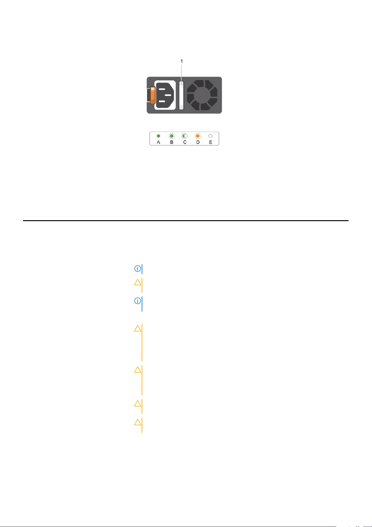
Figure 5. AC PSU status indicator
1. AC PSU status indicator/handle
Table 7. AC PSU status indicators
Convention Power indicator
pattern
A Green A valid power source is connected to the PSU and the PSU is operational.
B Flashing green When the firmware of the PSU is being updated, the PSU handle flashes green.
C Flashing green and
turns off
D Flashing amber Indicates a problem with the PSU.
Condition
When hot-adding a PSU, the PSU handle flashes green five times at 4 Hz rate and turns
off. This indicates a PSU mismatch with respect to efficiency, feature set, health status,
and supported voltage.
NOTE: Ensure that both the PSUs are of the same capacity.
CAUTION: For AC PSUs, use only PSUs with the Extended Power
Performance (EPP) label on the back.
NOTE: Mixing PSUs from previous generations of Dell PowerEdge servers can
result in a PSU mismatch condition or failure to turn the system on.
CAUTION: When correcting a PSU mismatch, replace only the PSU with the
flashing indicator. Swapping the PSU to make a matched pair can result in an
error condition and unexpected system shutdown. To change from a high
output configuration to a low output configuration or vice versa, you must
turn off the system.
CAUTION: AC PSUs support both 220 V and 110 V input voltages with the
exception of Titanium PSUs, which support only 220 V. When two identical
PSUs receive different input voltages, they can output different wattages,
and trigger a mismatch.
CAUTION: If two PSUs are used, they must be of the same type and have the
same maximum output power.
CAUTION: Combining AC and DC PSUs is not supported and triggers a
mismatch.
E Not lit Power is not connected.
14 About your system
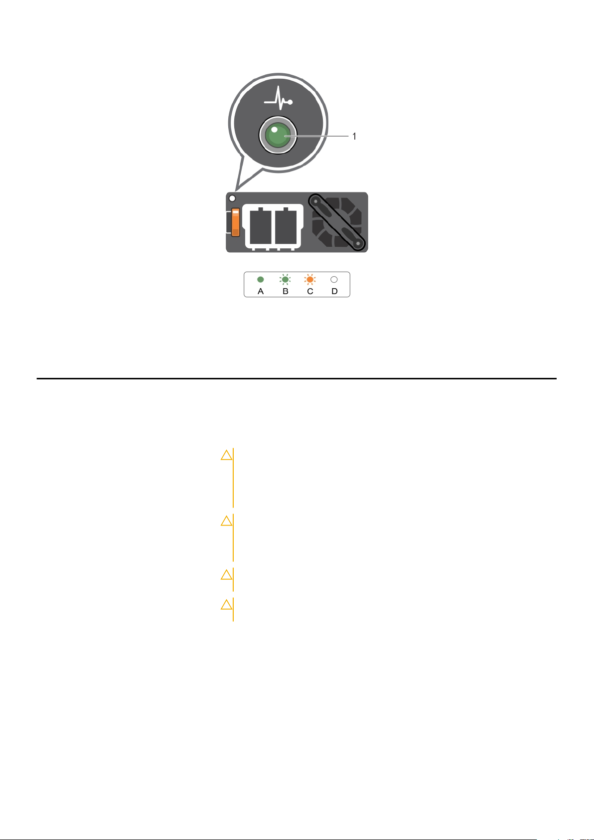
Figure 6. DC PSU status indicator
1. DC PSU status indicator
Table 8. DC PSU status indicators
Convention Power indicator pattern Condition
A Green A valid power source is connected to the PSU and that the PSU is operational.
B Flashing green When hot-adding a PSU, the PSU indicator flashes green. This indicates that there is a
PSU mismatch with respect to efficiency, feature set, health status, and supported
voltage. Ensure that both the PSUs are of the same capacity.
C Flashing amber Indicates a problem with the PSU.
CAUTION: When correcting a PSU mismatch, replace only the PSU with the
flashing indicator. Swapping the PSU to make a matched pair can result in
an error condition and unexpected system shutdown. To change from a
High Output configuration to a Low Output configuration or vice versa, you
must turn off the system.
CAUTION: AC PSU support both 220 V and 110 V input voltages with the
exception of Titanium PSU, which support only 220 V. When two identical
PSU receive different input voltages, they can output different wattages,
and trigger a mismatch.
CAUTION: If two PSU are used, they must be of the same type and have the
same maximum output power.
CAUTION: Combining AC and DC PSU is not supported and triggers a
mismatch.
D Not lit Power is not connected.
Locating Service Tag of your system
Your system is identified by a unique Express Service Code and Service Tag number. The Express Service Code is and Service Tag are
found on the front of the system by pulling out the information tag. Alternatively, the information may be on a sticker on the chassis of the
system. This information is used by Dell to route support calls to the appropriate personnel.
About your system
15

Documentation resources
This section provides information about the documentation resources for your system.
Task Document Location
2
Setting up your system For information about installing the system into a
rack, see the Rack documentation included with
your rack solution.
For information about turning on the system and
the technical specifications of your system, see the
Getting Started With Your System document that
shipped with your system.
For information about procedures for setting up
the storage system and internal storage, see
Setting up Your Dell Storage Network Attached
Storage System.
Configuring your system For information about configuring, managing,
updating, and restoring the system, see the Dell
EMC Network Attached Storage System using
Windows Storage Server 2016 Administrator's
Guide.
For information about the iDRAC features,
configuring and logging in to iDRAC, and managing
your system remotely, see the Integrated Dell
Remote Access Controller User's Guide.
For information about understanding Remote
Access Controller Admin (RACADM)
subcommands and supported RACADM interfaces,
see the RACADM Command Line Reference Guide
for iDRAC.
For information about updating drivers and
firmware.
Troubleshooting your system For information about troubleshooting the
hardware issues, see the Dell EMC Network
Attached Storage Systems using Windows
Storage Server 2016 Troubleshooting Guide.
Managing your system For information about the features of the Dell
OpenManage Systems Management, see the Dell
OpenManage Systems Management Overview
Guide.
For information about setting up, using, and
troubleshooting OpenManage, see the Dell
OpenManage Server Administrator User’s Guide.
For information about installing, using, and
troubleshooting Dell OpenManage Essentials, see
the Dell OpenManage Essentials User’s Guide.
For information about installing and using Dell
System E-Support Tool (DSET), see the Dell
System E-Support Tool (DSET) User's Guide.
www.dell.com/storagemanuals
www.dell.com/storagemanuals
www.dell.com/idracmanuals
www.dell.com/idracmanuals
www.dell.com/support/drivers
www.dell.com/storagemanuals
www.dell.com/
openmanagemanuals>OpenManage Essentials
www.dell.com/
openmanagemanuals>OpenManage Server
Administrator
www.dell.com/
openmanagemanuals>OpenManage Essentials
www.dell.com/DSET
16 Documentation resources

Task Document Location
Working with the Dell EMC
PowerEdge RAID controllers
Understanding event and error
messages
For understanding the features of Dell Lifecycle
Controller, see the Dell Lifecycle Controller User’s
Guide.
For information about enterprise systems
management partner programs, see the
OpenManage Connections Enterprise Systems
Management documents.
For information about connections and client
systems management, see the OpenManage
Connections Client Systems Management
documentation.
For information about understanding the features
of the Dell PowerEdge RAID controllers (PERC)
and deploying the PERC cards, see the Storage
controller documentation.
For information about checking the event and
error messages generated by the system firmware
and agents that monitor system components, see
the Event and Error Message Reference Guide for
14th Generation Dell EMC PowerEdge Servers.
www.dell.com/idracmanuals
www.dell.com/
omconnectionsenterprisesystemsmanagement
www.dell.com/dellclientcommandsuitemanuals
www.dell.com/storagecontrollermanuals
www.dell.com/
openmanagemanuals>OpenManage Software
Documentation resources 17

Technical specifications
Table 9. Processor specifications
Processor
Processor type One or two Haswell processor E5-2600 v3 product family
Table 10. Power specifications
Power
AC power supply (per power supply)
Wattage 750 W, or 1100 W
Heat dissipation
NOTE: Heat dissipation is calculated using the power
supply wattage rating.
2891 BTU/hr maximum (750 W power supply)
2843 BTU/hr maximum (750 W Titanium power supply)
4100 BTU/hr maximum (1100 W power supply)
4416 BTU/hr maximum (DC1100W power supply)
2891 BTU/hr maximum (750 W mixed mode power supply)
3
Voltage
NOTE: This system is also designed to be connected to
IT power systems with a phase to phase voltage not
exceeding 230 V.
100–240 V AC, autoranging, 50/60 Hz
Or
200–240 V AC, autoranging, 50/60 Hz, for 750 W Titanium
power supply
Table 10. Power specifications
DC power supply (per power supply)
Wattage 1100 W or 750 W (Platinum power supply for China only)
Heat dissipation
NOTE: Heat dissipation is calculated using the power
supply wattage rating.
Voltage
NOTE: This system is also designed to be connected to
IT power systems with a phase to phase voltage not
exceeding 230 V.
System battery CR 2032 3.0-V lithium coin cell
4416 BTU/hour maximum
–(48–60) V DC
Table 11. Expansion bus specification
Expansion Bus
Bus type PCI Express Generation 3
Expansion cards For a list of supported expansion cards, see the Expansion cards
and expansion-card risers section in this document.
Expansion slots using riser card:
Riser 1 (Slot 1) One half-height, low-profile x8 link
(Slot 2) One half-height, low-profile x8 link
(Slot 3) One half-height, low-profile x8 link
Riser 2 (Slot 4) One full-height, full-length x16 link
18 Technical specifications

Table 11. Expansion bus specification (continued)
Expansion Bus
NOTE: To use slots 1–4, both the processors must be
installed.
(Slot 5) One full-height, full-length x8 link
Riser 3 (default) (Slot 6) One full-height, full-length x8 link
(Slot 7) One full-height, full-length x8 link
Riser 3 (alternate for GPU) (Slot 6) One full-height, full-length x16 link
Table 12. Memory specifications
Memory
Architecture 1333 MT/s, 1600 MT/s, 1866 MT/s, or 2133 MT/s DDR4
registered, load-reduced Error Correcting Code (ECC) DIMMs
Support for advanced ECC or memory optimized operation
Memory module sockets Twenty-four 288-pin
Memory module capacities
LRDIMMs 32 GB quad-ranked
RDIMMs 4 GB single-ranked, 8 GB, or 16 GB dual-ranked
Minimum RAM 4 GB with a single processor
8 GB with a dual processor (minimum one memory module per
processor)
Maximum RAM Up to 768 GB with a dual processor
Up to 384 GB with a single processor
Table 13. Drive specification
Hard Drives
Twelve plus two–hard-drive systems Up to twelve 3.5 inch and two optional 2.5 inch back-accessible, internal, hot-
swappable SAS, SATA, SAS/SATA SSD, or Nearline SAS drives in hard-drive
slots 0–11 and 12–13.
Table 14. Connector specification
Connectors
Back
NIC Four 1 Gbps, two 1 Gbps plus two 10 Gbps, or four 10 Gbps
Serial 9-pin, DTE, 16550-compatible
USB Two 4-pin, USB 3.0-compliant
Video 15-pin VGA
External vFlash card One flash memory card slot with iDRAC8 Enterprise card
NOTE: The card slot is available for use only if the
iDRAC8 Enterprise license is installed on your system.
Front
USB
One 4-pin, USB 2.0-compliant
One USB management port/iDRAC Direct
Video 15-pin VGA
Internal
Technical specifications 19

Table 14. Connector specification (continued)
Connectors
USB One 4-pin, USB 3.0-compliant
Internal Dual SD Module Two optional flash memory card slots with the internal SD module
NOTE: One card slot is dedicated for redundancy.
Table 15. Video specification
Video
Video type Matrox G200eR2
Video memory 16 MB
Table 16. Dimensions and weight
Physical
Height 8.73 cm (3.44 inch)
Width 48.2 cm (18.98 inch)
Depth 75.58 cm (29.75 inch)
Maximum configuration weight
• 30.4 kg (67.02 lb) (2.5-inch hard drive systems)
• 36.5 kg (80.47 lb) (3.5-inch hard drive systems)
Empty weight
• 19 kg (41.89 lb) (2.5-inch hard drive systems)
• 23.2 kg (51.15 lb) (3.5-inch hard drive systems)
Table 17. Expanded operating temperature
Expanded Operating Temperature
NOTE: When operating in the expanded temperature range, system performance may be impacted.
NOTE: When operating in the expanded temperature range, ambient temperature warnings may be reported on the
LCD and in the System Event Log.
< 10% of annual operating hours Continuous Operation 5 °C–40°C at 5% to 85% RH with 29°C
dew point.
NOTE: Outside the standard operating temperature
(10°C–35°C), the system can operate continuously
down to 5°C or as high as 40°C.
For temperatures between 35°C- 40°C, derate maximum
allowable temperature by 1°C per 175 m above 950 m (1°F per
319 ft).
< 1% of annual operating hours –5 °C–45°C at 5% to 90% RH with 29°C (84.2°F) maximum
dew point.
NOTE: Outside the standard operating temperature
(10°C–35°C), the system can operate down to –5°C or
up to 45°C for a maximum of 1% of its annual operating
hours.
Expanded Operating Temperature Restrictions
20 Technical specifications
For temperatures between 40 °C–45 °C, derate maximum
allowable dry bulb temperature by 1°C per 125 m above 950 m
(1°F per 228 ft).
• Do not perform a cold startup below 5°C.
• The operating temperature specified is for a maximum altitude
of 3050 m (10,000 ft).
• 160 W (10 core) processor is not supported.

Table 17. Expanded operating temperature (continued)
Expanded Operating Temperature
• Tape Backup Unit (TBU) is not supported.
• Redundant power supplies are required.
• Non Dell qualified peripheral cards and/or peripheral cards
greater than 25 W are not supported.
• PCIe SSD and GPU is not supported.
• Maximum 120 W processor supported on 3.5 inch hard drive
chassis.
• Maximum 145 W processor supported on 2.5 inch hard drive
chassis.
• Only SSDs are allowed in the hard drive slots at the back of
the 3.5 inch hard drive chassis.
Table 18. Environmental specification
Environmental
NOTE: For additional information about environmental measurements for specific system configurations, see Dell.com/
environmental_datasheets.
Temperature
Storage –40°C–65°C (–40°F–149°F)
Continuous operation (for altitude less than 950 m or 3117 ft) 10°C to 35°C (50°F to 95°F) with no direct sunlight on the
equipment.
Fresh air For information on fresh air, see Expanded Operating
Temperature section.
Maximum temperature gradient (operating and storage) 20°C/h (36°F/h)
Relative humidity
Storage 5% to 95% RH with 33°C (91 °F) maximum dew point.
Atmosphere must be non-condensing always.
Operating 10% to 80% Relative Humidity with 29°C (84.2°F) maximum
dew point.
Maximum vibration
Operating 0.26 G
Storage 1.87 G
at 5 Hz to 350 Hz (all operation orientations).
rms
at 10 Hz to 500 Hz for 15 min (all six sides tested).
rms
Maximum shock
Operating Six consecutively executed shock pulses in the positive and
negative x, y, and z axes of 40 G for up to 2.3 ms.
Storage Six consecutively executed shock pulses in the positive and
negative x, y, and z axes (one pulse on each side of the
system) of 71 G for up to 2 ms.
Maximum altitude
Operating
3,048 (10,000 ft)
Storage 12,000 m (39,370 ft).
Operating altitude de-rating
Up to 35°C (95°F) Maximum temperature is reduced by 1°C/300 m (1°F/547 ft)
above 950 m (3,117 ft).
35 °C–40°C (95 °F–104°F) Maximum temperature is reduced by 1°C/175 m (1°F/319 ft)
above 950 m (3,117 ft).
Technical specifications 21

Table 18. Environmental specification (continued)
Environmental
40 °C–45°C (104 °F–113°F) Maximum temperature is reduced by 1°C/125 m (1°F/228 ft)
above 950 m (3,117 ft).
Particulate contamination
NOTE: This section defines the limits to help avoid IT equipment damage and/or failure from particulates and gaseous
contamination. If it is determined that levels of particulates or gaseous pollution are beyond the limits specified below
and are the reason for the damage and/or failures to your equipment, it may be necessary for you to re-mediate the
environmental conditions that are causing the damage and/or failures. Re-mediation of environmental conditions will
be the responsibility of the customer.
Air filtration
NOTE: Applies to data center environments only. Air
filtration requirements do not apply to IT equipment
designed to be used outside a data center, in
environments such as an office or factory floor.
Conductive dust
NOTE: Applies to data center and non-data center
environments.
Corrosive dust
NOTE: Applies to data center and non-data center
environments.
Gaseous contamination
NOTE: Maximum corrosive contaminant levels measured at ≤50% relative humidity.
Copper coupon corrosion rate <300 Å/month per Class G1 as defined by ANSI/
Silver coupon corrosion rate <200 Å/month as defined by AHSRAE TC9.9.
Related References
Expansion cards and expansion card riser on page 69
Data center air filtration as defined by ISO Class 8 per ISO
14644-1 with a 95 percent upper confidence limit.
NOTE: Air entering the data center must have
MERV11 or MERV13 filtration.
Air must be free from conductive dust, zinc whiskers, or other
conductive particles.
• Air must be free of corrosive dust.
• Residual dust present in the air must have a deliquescent
point less than 60% relative humidity.
ISA71.04-1985.
22
Technical specifications

Initial system setup and configuration
Topics:
• Setting up your system
• Options to set up iDRAC IP address
• Log in to iDRAC
• Managing your system remotely
• Methods to download firmware and drivers
Setting up your system
Complete the following steps to set up your system:
Steps
1. Unpack the system.
2. Install the system into the rack. For more information about installing the system into the rack, see your system Rack Installation
Placemat at Dell.com/poweredgemanuals.
3. Connect the peripherals to the system.
4. Connect the system to its electrical outlet.
5. Turn the system on by pressing the power button or by using iDRAC.
6. Turn on the attached peripherals.
4
Options to set up iDRAC IP address
You must configure the initial network settings based on your network infrastructure to enable the communication to and from iDRAC.
You can set up the IP address by using one of the following interfaces:
Interfaces
iDRAC Settings
utility
Dell Deployment
Toolkit
Dell Lifecycle
Controller
Chassis or Server
LCD panel
You must use the default iDRAC IP address 192.168.0.120 to configure the initial network settings, including setting up DHCP or a static IP
for iDRAC.
To access iDRAC, ensure that you install the iDRAC port card or connect the network cable to the Ethernet
NOTE:
connector 1 on the system board.
NOTE: Ensure that you change the default user name and password after setting up the iDRAC IP address.
Document/Section
See Dell Integrated Dell Remote Access Controller User's Guide at Dell.com/idracmanuals
See Dell Deployment Toolkit User’s Guide at Dell.com/openmanagemanuals
See Dell Lifecycle Controller User’s Guide at Dell.com/idracmanuals
See the LCD panel section
Log in to iDRAC
You can log in to iDRAC as:
• iDRAC user
Initial system setup and configuration 23

• Microsoft Active Directory user
• Lightweight Directory Access Protocol (LDAP) user
The default user name and password are root and calvin. You can also log in by using Single Sign-On or Smart Card.
NOTE: You must have iDRAC credentials to log in to iDRAC.
For more information about logging in to iDRAC and iDRAC licenses, see the latest Integrated Dell Remote Access Controller User's Guide
at http://www.dell.com/support/home/us/en/19/Products/software/remote_ent_sys_mgmt/rmte_ent_sys_rmte_access_cntrllr.
Managing your system remotely
To perform out-of-band systems management by using iDRAC, configure iDRAC for remote accessibility, set up the management station
and managed system, and configure the supported web browsers. For more information, see the Integrated Dell Remote Access
Controller User’s Guide at Dell.com/idracmanuals.
You can also remotely monitor and manage the server by using the Dell OpenManage Server Administrator (OMSA) software and
OpenManage Essentials (OME) systems management console. For more information, see Dell.com/openmanagemanuals >
OpenManage Server Administrator or Dell.com/openmanagemanuals > OpenManage Essentials.
Methods to download firmware and drivers
You can download the firmware and drivers from the Dell Support site available at Dell.com/DHMSmanuals.
24 Initial system setup and configuration

Pre-operating system management
applications
You can manage basic settings and features of a system without booting to the operating system by using the system firmware.
Topics:
• Options to manage the pre-operating system applications
• System Setup
• Dell Lifecycle Controller
• Boot Manager
• PXE boot
Options to manage the pre-operating system applications
Your system has the following options to manage the pre-operating system applications:
• System Setup
• Boot Manager
• Dell Lifecycle Controller
• Preboot Execution Environment (PXE)
5
System Setup
By using the System Setup screen, you can configure the BIOS settings, iDRAC settings, and device settings of your system.
NOTE:
Help text for the selected field is displayed in the graphical browser by default. To view the help text in the text
browser, press F1.
You can access system setup by using two methods:
• Standard graphical browser — The browser is enabled by default.
• Text browser — The browser is enabled by using Console Redirection.
Viewing System Setup
To view the System Setup screen, perform the following steps:
Steps
1. Turn on, or restart your system.
2. Press F2 immediately after you see the following message:
F2 = System Setup
If your operating system begins to load before you press F2, wait for the system to finish booting, and then
NOTE:
restart your system and try again.
Pre-operating system management applications 25

System Setup details
The System Setup Main Menu screen details are explained as follows:
Option Description
System BIOS Enables you to configure BIOS settings.
iDRAC Settings Enables you to configure iDRAC settings.
The iDRAC settings utility is an interface to set up and configure the iDRAC parameters by using UEFI (Unified
Extensible Firmware Interface). You can enable or disable various iDRAC parameters by using the iDRAC settings
utility. For more information about this utility, see Integrated Dell Remote Access Controller User’s Guide at
Dell.com/idracmanuals.
Device Settings Enables you to configure device settings.
System BIOS
You can use the System BIOS screen to edit specific functions such as boot order, system password, setup password, set the RAID
mode, and enable or disable USB ports.
Viewing System BIOS
To view the System BIOS screen, perform the following steps:
Steps
1. Turn on, or restart your system.
2. Press F2 immediately after you see the following message:
F2 = System Setup
NOTE:
If your operating system begins to load before you press F2, wait for the system to finish booting, and then
restart your system and try again.
3. On the System Setup Main Menu screen, click System BIOS.
System BIOS Settings details
About this task
The System BIOS Settings screen details are explained as follows:
Option
System
Information
Memory Settings Specifies information and options related to the installed memory.
Processor
Settings
SATA Settings Specifies options to enable or disable the integrated SATA controller and ports.
Boot Settings Specifies options to specify the boot mode (BIOS or UEFI). Enables you to modify UEFI and BIOS boot settings.
Network Settings Specifies options to change the network settings.
Integrated Devices Specifies options to manage integrated device controllers and ports and specify related features and options.
Serial
Communication
System Profile
Settings
Description
Specifies information about the system such as the system model name, BIOS version, and Service Tag.
Specifies information and options related to the processor such as speed and cache size.
Specifies options to manage the serial ports and specify related features and options.
Specifies options to change the processor power management settings, memory frequency, and so on.
26 Pre-operating system management applications

Option Description
System Security Specifies options to configure the system security settings, such as system password, setup password, Trusted
Platform Module (TPM) security. It also manages the power and NMI buttons on the system.
Miscellaneous
Settings
Specifies options to change the system date, time, and so on.
Boot Settings
You can use the Boot Settings screen to set the boot mode to either BIOS or UEFI. It also enables you to specify the boot order.
Viewing Boot Settings
To view the Boot Settings screen, perform the following steps:
Steps
1. Turn on, or restart your system.
2. Press F2 immediately after you see the following message:
F2 = System Setup
NOTE: If your operating system begins to load before you press F2, wait for the system to finish booting, and then
restart your system and try again.
3. On the System Setup Main Menu screen, click System BIOS.
4. On the System BIOS screen, click Boot Settings.
Boot Settings details
About this task
The Boot Settings screen details are explained as follows:
Option
Boot Mode Enables you to set the boot mode of the system.
Boot Sequence
Retry
Hard-Disk Failover Specifies the hard drive that is booted in the event of a hard drive failure. The devices are selected in the Hard-
Boot Option
Settings
BIOS Boot
Settings
Description
CAUTION: Switching the boot mode may prevent the system from booting if the operating system
is not installed in the same boot mode.
If the operating system supports UEFI, you can set this option to UEFI. Setting this field to BIOS allows
compatibility with non-UEFI operating systems. This option is set to BIOS by default.
NOTE: Setting this field to UEFI disables the BIOS Boot Settings menu. Setting this field to BIOS
disables the UEFI Boot Settings menu.
Enables or disables the Boot Sequence Retry feature. If this option is set to Enabled and the system fails to boot,
the system reattempts the boot sequence after 30 seconds. This option is set to Enabled by default.
Disk Drive Sequence on the Boot Option Setting menu. When this option is set to Disabled, only the first
hard drive in the list is attempted to boot. When this option is set to Enabled, all hard drives are attempted to
boot in the order selected in the Hard-Disk Drive Sequence. This option is not enabled for UEFI Boot Mode.
Configures the boot sequence and the boot devices.
Enables or disables BIOS boot options.
NOTE: This option is enabled only if the boot mode is BIOS.
UEFI Boot
Settings
Enables or disables UEFI Boot options. The Boot options include IPv4 PXE and IPv6 PXE. This option is set to
IPv4 by default.
NOTE: This option is enabled only if the boot mode is UEFI.
Pre-operating system management applications 27

Choosing the system boot mode
System Setup enables you to specify one of the following boot modes for installing your operating system:
• BIOS boot mode (the default) is the standard BIOS-level boot interface.
• Unified Extensible Firmware Interface (UEFI) (the default) boot mode is an enhanced 64-bit boot interface. If you have configured
your system to boot to UEFI mode, it replaces the system BIOS.
1. From the System Setup Main Menu, click Boot Settings, and select Boot Mode.
2. Select the boot mode you want the system to boot into.
CAUTION: Switching the boot mode may prevent the system from booting if the operating system is not installed in
the same boot mode.
3. After the system boots in the specified boot mode, proceed to install your operating system from that mode.
NOTE: Operating systems must be UEFI-compatible to be installed from the UEFI boot mode. DOS and 32-bit operating
systems do not support UEFI and can only be installed from the BIOS boot mode.
NOTE: For the latest information about supported operating systems, go to Dell.com/ossupport.
Changing the boot order
You may have to change the boot order if you want to boot from a USB key or an optical drive. The following instructions may vary if you
have selected BIOS for Boot Mode.
Steps
1. On the System Setup Main Menu screen, click System BIOS > Boot Settings.
2. Click Boot Option Settings > Boot Sequence.
3. Use the arrow keys to select a boot device, and use the plus (+) and minus (-) sign keys to move the device down or up in the order.
4. Click Exit, and then click Yes to save the settings on exit.
Network Settings
You can use the Network Settings screen to modify PXE device settings. The network settings option is available only in the UEFI mode.
NOTE:
The BIOS does not control network settings in the BIOS mode. For the BIOS boot mode, the optional Boot ROM
of the network controllers handles the network settings.
Viewing Network Settings
To view the Network Settings screen, perform the following steps:
Steps
1. Turn on, or restart your system.
2. Press F2 immediately after you see the following message:
F2 = System Setup
NOTE:
If your operating system begins to load before you press F2, wait for the system to finish booting, and then
restart your system and try again.
3. On the System Setup Main Menu screen, click System BIOS.
4. On the System BIOS screen, click Network Settings.
28
Pre-operating system management applications

Network Settings screen details
The Network Settings screen details are explained as follows:
About this task
Option Description
PXE Device n (n =
1 to 4)
PXE Device n
Settings(n = 1 to
4)
Enables or disables the device. When enabled, a UEFI boot option is created for the device.
Enables you to control the configuration of the PXE device.
UEFI iSCSI Settings
You can use the iSCSI Settings screen to modify iSCSI device settings. The iSCSI Settings option is available only in the UEFI boot mode.
BIOS does not control network settings in the BIOS boot mode. For the BIOS boot mode, the option ROM of the network controller
handles the network settings.
Viewing UEFI iSCSI Settings
To view the UEFI iSCSI Settings screen, perform the following steps:
Steps
1. Turn on, or restart your system.
2. Press F2 immediately after you see the following message:
F2 = System Setup
NOTE:
If your operating system begins to load before you press F2, wait for the system to finish booting, and then
restart your system and try again.
3. On the System Setup Main Menu screen, click System BIOS.
4. On the System BIOS screen, click Network Settings.
5. On the Network Settings screen, click UEFI iSCSI Settings.
UEFI iSCSI Settings details
The UEFI ISCSI Settings screen details are explained as follows:
Option
ISCSI Initiator
Name
ISCSI Device n (n
= 1 to 4)
Description
Specifies the name of the iSCSI initiator (iqn format).
Enables or disables the iSCSI device. When disabled, a UEFI boot option is created for the iSCSI device
automatically.
System Security
You can use the System Security screen to perform specific functions such as setting the system password, setup password and
disabling the power button.
Viewing System Security
To view the System Security screen, perform the following steps:
Steps
1. Turn on, or restart your system.
2. Press F2 immediately after you see the following message:
F2 = System Setup
Pre-operating system management applications
29

NOTE: If your operating system begins to load before you press F2, wait for the system to finish booting, and then
restart your system and try again.
3. On the System Setup Main Menu screen, click System BIOS.
4. On the System BIOS screen, click System Security.
System Security Settings details
About this task
The System Security Settings screen details are explained as follows:
Option Description
Intel AES-NI Improves the speed of applications by performing encryption and decryption by using the Advanced Encryption
Standard Instruction Set (AES-NI). This option is set to Enabled by default.
System Password Sets the system password. This option is set to Enabled by default and is read-only if the password jumper is not
installed in the system.
Setup Password Sets the setup password. This option is read-only if the password jumper is not installed in the system.
Password Status Locks the system password. This option is set to Unlocked by default.
TPM Security
TPM Information Changes the operational state of the TPM. This option is set to No Change by default.
TPM Status Specifies the TPM status.
TPM Command
NOTE: The TPM menu is available only when the TPM module is installed.
Enables you to control the reporting mode of the TPM. The TPM Security option is set to Off by default. You
can only modify the TPM Status, TPM Activation, and Intel TXT fields if the TPM Status field is set to either On
with Pre-boot Measurements or On without Pre-boot Measurements.
CAUTION: Clearing the TPM results in the loss of all keys in the TPM. The loss of TPM keys may
affect booting to the operating system.
Clears all the contents of the TPM. The TPM Clear option is set to No by default.
Intel TXT Enables or disables the Intel Trusted Execution Technology (TXT) option. To enable the Intel TXT option,
virtualization technology and TPM Security must be enabled with Pre-boot measurements. This option is set to
Off by default.
Power Button Enables or disables the power button on the front of the system. This option is set to Enabled by default.
NMI Button Enables or disables the NMI button on the front of the system. This option is set to Disabled by default.
AC Power
Recovery
AC Power
Recovery Delay
User Defined
Delay (60s to
240s)
UEFI Variable
Access
Secure Boot Enables Secure Boot, where the BIOS authenticates each pre-boot image by using the certificates in the Secure
Secure Boot
Policy
Secure Boot
Policy Summary
Sets how the system behaves after AC power is restored to the system. This option is set to Last by default.
Sets the time delay for the system to power up after AC power is restored to the system. This option is set to
Immediate by default.
Sets the User Defined Delay option when the User Defined option for AC Power Recovery Delay is selected.
Provides varying degrees of securing UEFI variables. When set to Standard (the default), UEFI variables are
accessible in the operating system per the UEFI specification. When set to Controlled, selected UEFI variables
are protected in the environment and new UEFI boot entries are forced to be at the end of the current boot
order.
Boot Policy. Secure Boot is disabled by default.
When Secure Boot policy is set to Standard, the BIOS uses the system manufacturer’s key and certificates to
authenticate pre-boot images. When Secure Boot policy is set to Custom, the BIOS uses the user-defined key
and certificates. Secure Boot policy is set to Standard by default.
Specifies the list of certificates and hashes that secure boot uses to authenticate images.
30 Pre-operating system management applications
 Loading...