

Page 1

Dell Precision Workstation 470 and 670 Computers User's Guide
Dell Precision™ Workstation 470 and 670 Computers
User's Guide
Information About Your Computer
Your Dell Precision™ 670 Computer
Your Dell Precision™ 470 Computer
Advanced Features
RAID
Removing and Replacing Parts
Model WHM and WHL
For information on other documentation included with your computer, see "Finding Information."
Tools to Help Solve Problems
Solving Problems
Cleaning Your Computer
Features of Microsoft Windows XP
Appendix
Glossary
Notes, Notices, and Cautions
NOTE: A NOTE indicates important information that helps you make better use of your computer.
NOTICE: A NOTICE indicates either potential damage to hardware or loss of data and tells you how to avoid the
problem.
CAUTION: A CAUTION indicates a potential for property damage, personal injury, or death.
Abbreviations and Acronyms
For a complete list of abbreviations and acronyms, see the "Glossary."
If you purchased a Dell™ n Series computer, any references in this document to Microsoft® Windows® operating systems are
not applicable.
The Drivers and Utilities CD, Quick Reference Guide, and Operating System CD are optional and may not ship with your
computer.
Information in this document is subject to change without notice.
© 2004–2006 Dell Inc. All rights reserved.
Reproduction in any manner whatsoever without the written permission of Dell Inc. is strictly forbidden.
Trademarks used in this text: Dell, the DELL logo, Inspiron, Dell Precision, Dimension, OptiPlex, Latitude, PowerEdge, PowerVault, PowerApp, Axim ,
and Dell OpenManage are trademarks of Dell Inc.; Red Hat is a registered trademark of Red Hat, Inc.; Intel is a registered trademark and Xeon is
a trademark of Intel Corporation; Microsoft and Windows are registered trademarks of Microsoft Corporation.
Other trademarks and trade names may be used in this document to refer to either the entities claiming the marks and names or their products.
Dell Inc. disclaims any proprietary interest in trademarks and trade names other than its own.
Models WHM and WHL
September 2006 P/N U3524 Rev. A04
file:///T|/htdocs/systems/ws670/EN/ug_en/index.htm[3/20/2013 9:31:41 AM]
Page 2
Information About Your Computer: Dell Precision Workstation 470 and 670 Computers User's Guide
Back to Contents Page
Information About Your Computer
Dell Precision™ Workstation 470 and 670 Computers User's Guide
Finding Information
Specifications
Caring for Your Computer
Finding Information
What Are You Looking For? Find it Here
A diagnostic program for
my computer
Drivers for my computer
My device documentation
Desktop System Software
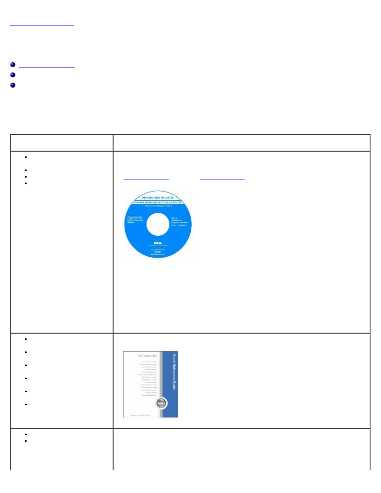
Drivers and Utilities CD (also known as the ResourceCD)
Documentation and drivers are already installed on your computer. You can use the CD
to reinstall drivers
Readme files may be included on your CD to provide last-minute updates about
technical changes to your computer or advanced technical-reference material for
technicians or experienced users.
NOTE: The latest drivers and documentation updates can be found at
support.dell.com.
NOTE: The Drivers and Utilities CD is optional and may not ship with your computer.
or run the Dell Diagnostics.
How to set up my
computer
How to care for my
computer
Troubleshooting
information
How to run the Dell
Diagnostics
Error codes and diagnostic
lights
How to open my computer
cover
System board connectors
Location of system board
components
file:///T|/htdocs/systems/ws670/EN/ug_en/about.htm[3/20/2013 9:31:42 AM]
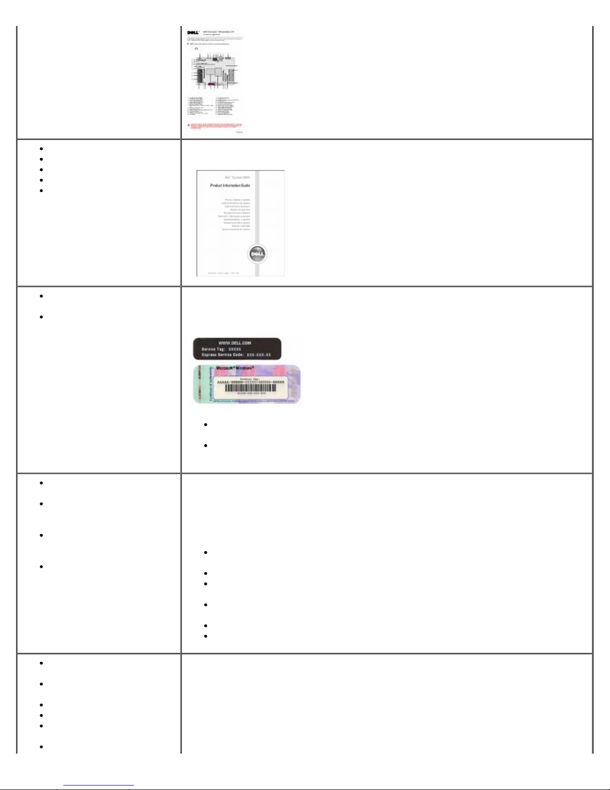
Quick Reference Guide
System Information Label
Located on the inside cover of your computer.
NOTE: This document is available as a PDF at
support.dell.com.
NOTE: The Quick Reference Guide is optional and may not ship
with your computer.
Page 3
Information About Your Computer: Dell Precision Workstation 470 and 670 Computers User's Guide
Warranty information
Safety instructions
Regulatory information
Ergonomics information
End User License
Agreement
Service Tag and Express
Service Code
Microsoft Windows License
Label
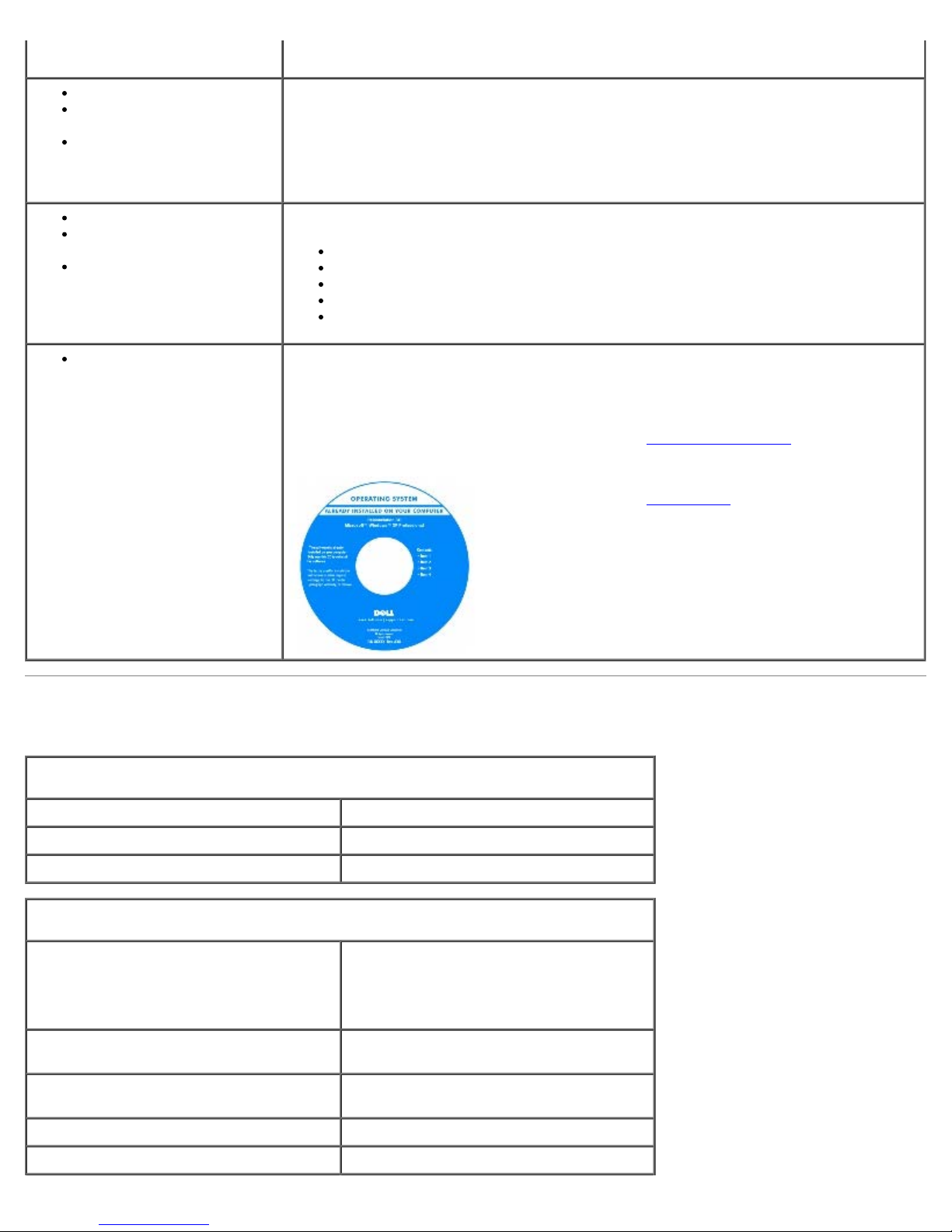
Dell™ Product Information Guide
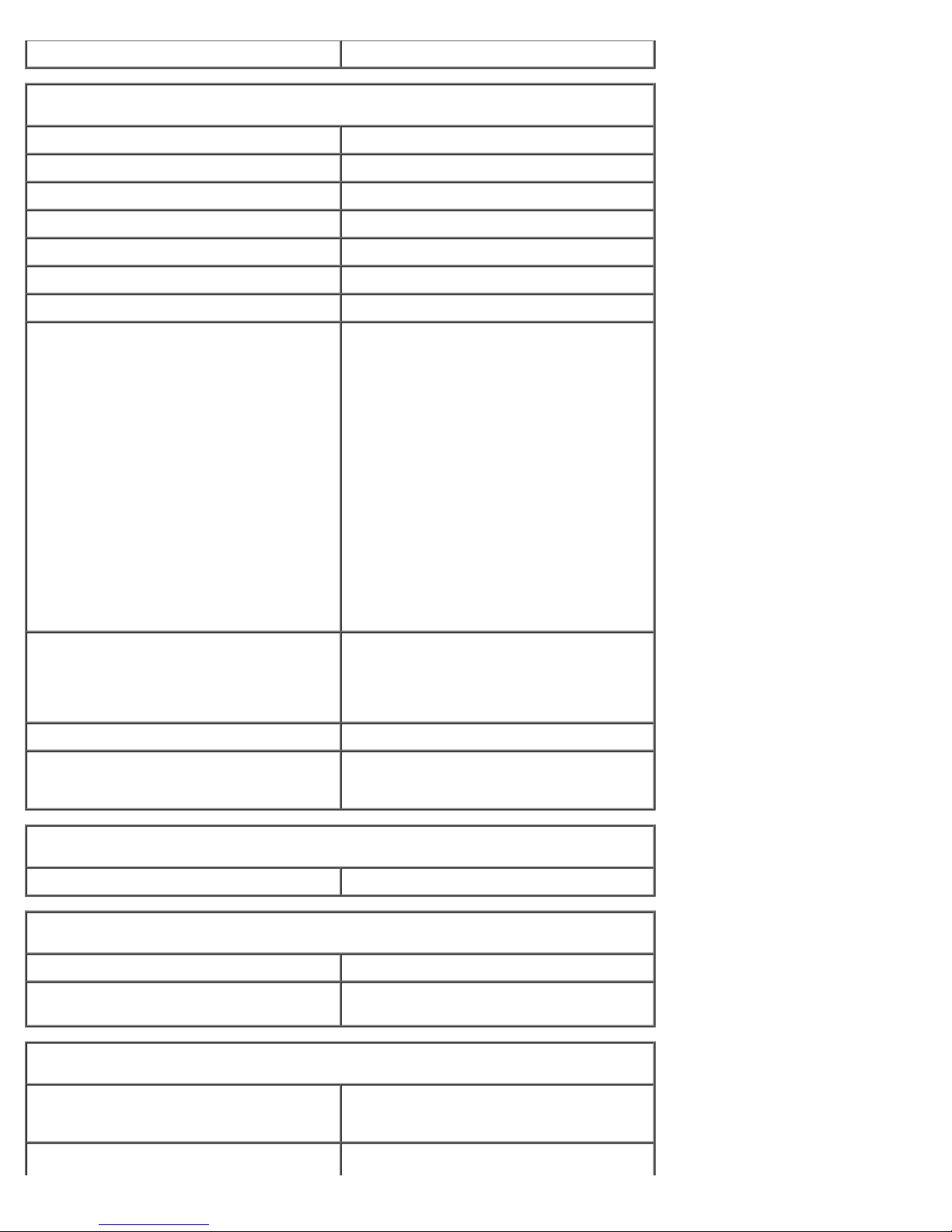
Service Tag and Microsoft Windows License
These labels are located on your computer.
Use the Service Tag to identify your computer when you use support.dell.com
or contact technical support.
Enter the Express Service Code to direct your call when contacting technical
support. The Express Service Code is not available in all countries.
Latest drivers for my
computer
Answers to technical
service and support
questions
Online discussions with
other users and technical
support
Documentation for my
computer
Service call status and
support history
Top technical issues for my
computer
Frequently asked questions
File downloads
Details on my computer
configuration
Service contract for my
Dell Support Website — support.dell.com
NOTE: Select your region to view the appropriate support site.
The Dell Support website provides several online tools, including:
Solutions — Troubleshooting hints and tips, articles from technicians, and online
courses
Community — Online discussion with other Dell customers
Upgrades — Upgrade information for components, such as memory, the hard
drive, and the operating system
Customer Care — Contact information, order status, warranty, and repair
information
Downloads — Drivers, patches, and software updates
Reference — Computer documentation, product specifications, and white papers
Dell Premier Support Website — premiersupport.dell.com
The Dell Premier Support website is customized for corporate, government, and
education customers. This website may not be available in all regions.
file:///T|/htdocs/systems/ws670/EN/ug_en/about.htm[3/20/2013 9:31:42 AM]
Page 4
Information About Your Computer: Dell Precision Workstation 470 and 670 Computers User's Guide
computer
How to use Windows XP
Documentation for my
computer
Documentation for devices
(such as a modem)
How to use Red Hat® Linux
E-mail discussions with Dell
Precision® and Linux users
Additional information
regarding Linux and my
Dell Precision computer
How to reinstall my
operating system
Windows Help and Support Center
1. Click the Start button and click Help and Support.
2. Type a word or phrase that describes your problem and click the arrow icon.
3. Click the topic that describes your problem.
4. Follow the instructions on the screen.
Dell Supported Linux Sites
http://linux.dell.com
http://lists.us.dell.com/mailman/listinfo/linux-precision
http://docs.us.dell.com/docs/software/oslinux/
http://docs.us.dell.com/docs/software/OSRHEL3/
http://docs.us.dell.com/docs/software/OSRHEL4/
Operating System CD
The operating system is already installed on your computer. To reinstall your operating
system, use the Operating System CD. See this document for instructions.
After you reinstall your operating system, use the Drivers and Utilities
drivers for the devices that came with your computer.
Your operating system product key
computer.
label is located on your
CD to reinstall
NOTE: The color of your CD varies based on the operating
system you ordered.
NOTE: The Operating System CD is optional and may not
ship with your computer.
Specifications
Microprocessor
Microprocessor type Intel® Xeon™
Level 1 (L1) cache 8 KB
Level 2 (L2) cache 1024 KB
Memory
Type 400-MHz DDR2 SDRAM
NOTE: Your computer supports only
registered memory.
Memory connectors Dell Precision 470 computer: 6
Dell Precision 670 computer: 6
Memory capacities 256-MB, 512-MB, 1-GB, 2-GB, and 4-GB
ECC
Minimum memory 512 MB
Maximum memory 16 GB
file:///T|/htdocs/systems/ws670/EN/ug_en/about.htm[3/20/2013 9:31:42 AM]
Page 5
Information About Your Computer: Dell Precision Workstation 470 and 670 Computers User's Guide
BIOS address F0000h
Computer Information
Chipset Intel E7525
Data bus width 64 bits
Address bus width 36 bits
DMA channels eight
Interrupt levels 23
BIOS chip (NVRAM) 4 MB
Memory speed DDR2 400 MHz
NIC Integrated network interface with ASF
1.03 support as defined by DMTF
Capable of 10/100/1000 communication
Green — A good connection exists
between a 10-Mbps network and the
computer.
Orange — A good connection exists
between a 100-Mbps network and the
computer.
Yellow — A good connection exists
between a 1-Gb (or 1000-Mbps)
connection and the computer.
Off — The computer is not detecting a
physical connection to the network.
SCSI controller Dell Precision 470 computer — Add-in
U320 SCSI
Dell Precision 670 computer — Integrated
U320 SCSI
SATA controller SATA 1.5
System clock 800-MHz data rate
Video
Type PCI Express x16 150 W
Audio
Type AC97, Sound Blaster emulation
Stereo conversion 16-bit analog-to-digital; 20-bit digital-to-
analog
Expansion Bus
Bus type
one PCI Express x16 150 W
one PCI Express x4
Bus speed PCI: 33 MHz
file:///T|/htdocs/systems/ws670/EN/ug_en/about.htm[3/20/2013 9:31:42 AM]
Page 6
Information About Your Computer: Dell Precision Workstation 470 and 670 Computers User's Guide
PCIX: 100 MHz
PCI Express:
x4 slot bidirectional speed is 20
Gbps
x16 slot bidirectional speed is 80
Gbps
Dell Precision 470 computer
PCI
connector one
connector size 120 pins
connector data width (maximum) 32 bits
PCIX
connector one
connector size 188 pins
connector data width (maximum) 64 bits
PCI Express x16
connector one
connector size 164 pins
connector data width (maximum) 16 bits
PCI Express x8 (runs at x4 only)
connector one
connector size 98 pins
connector data width (maximum) 8 bits
Dell Precision 670 computer
PCI
connector one
connector size 120 pins
connector data width (maximum) 32 bits
PCIX
connectors three
connector size 188 pins
connector data width (maximum) 64 bits
PCI Express x16
connector one
connector size 164 pins
connector data width (maximum) 16 bits
PCI Express x8 (runs at x4 only)
connector one
connector size 98 pins
connector data width (maximum) 4 bits
file:///T|/htdocs/systems/ws670/EN/ug_en/about.htm[3/20/2013 9:31:42 AM]
Page 7
Information About Your Computer: Dell Precision Workstation 470 and 670 Computers User's Guide
Drives
Externally accessible:
Dell Precision 470 computer one floppy drive bay (for an optional
floppy drive)
two CD/DVD drive bays
Dell Precision 670 computer one floppy drive bay (for an optional
floppy drive)
three CD/DVD drive bays
Internally accessible:
Dell Precision 470 computer two bays for two 1-inch high or one 1.6-
inch high hard drives
Dell Precision 670 computer three bays for three 1-inch high or two
1.6-inch high hard drives
NOTE: You can purchase a conversion
bracket from Dell that allows you to use a
5.25-inch drive bay as an additional hard
drive bay.
Connectors
External connectors:
Serial two 9-pin connector; 16550C-compatible
Parallel one 25-hole connector (bidirectional)
IEEE 1394a Dell Precision 670 computer: two 6-pin
Network adapter RJ45 connector
PS/2 (keyboard and mouse) 6-pin mini-DIN
USB two front-panel and six back-panel USB
Audio Dell Precision 670 computer — Three
connectors
Dell Precision 470 computer: available
with add-in PCI IEEE 1394a card
2.0–compliant connectors
connectors for line-in, line-out, and
microphone on back panel; one
speaker/headphone and one microphone
connector on the front panel
Dell Precision 470 computer — Three
connectors for line-in, line-out, and
microphone on back panel; one
speaker/headphone on the front panel
System board connectors:
Primary IDE 40-pin connector on PCI local bus
Secondary IDE 40-pin connector on PCI local bus
Serial ATA (SATA_0 and SATA_1) 7-pin connector
Floppy 34-pin connector
Fan 5-pin connector
SCSI 68-pin connector (Dell Precision 670
computer)
file:///T|/htdocs/systems/ws670/EN/ug_en/about.htm[3/20/2013 9:31:42 AM]
Page 8
Information About Your Computer: Dell Precision Workstation 470 and 670 Computers User's Guide
I/O panel 34-pin connector
USB/IEEE 1394a 16-pin connector
CD drive audio interface 4-pin connector
Power_1 connector 24-pin connector
Power_2 connector 20 pin connector
Telephony (MODEM) 4-pin connector
Key Combinations
<Ctrl><Alt><Del> launches Windows task manager
<F2> starts embedded system setup (during
start-up only)
<F12> or <Ctrl><Alt><F8> boots from the network (during start-up
only)
<Ctrl><Alt><F10> launches the utility partition (if installed)
during computer start-up
<Ctrl><Alt><d> launches the hard-drive diagnostics utility
during computer start-up
Controls and Lights
Power control push button
Power light green light — Blinking green in sleep
state; solid green for power-on state.
amber light — Blinking amber indicates a
problem with an installed device; solid
amber indicates an internal power
problem (see "Power Problems
").
Hard-drive access light green
Link integrity light (on integrated network
adapter)
green light for 10-Mb operation; orange
light for 100-Mb operation; yellow light
for a 1000-Mb (1-Gb) operation
Activity light (on integrated network
yellow blinking light
adapter)
Diagnostic lights four lights on the front panel
Standby power light AUX_PWR on the system board
Memory power light AUX_LED on the system board (blinks in
S1 or S3 suspend mode)
Power
DC power supply:
Wattage Dell Precision 670 computer: 650 W
Dell Precision 470 computer: 550 W
Heat dissipation Dell Precision 670 computer: 2218 BTU/hr
Dell Precision 470 computer: 1877 BTU/hr
Note: Heat dissipation is calculated based
upon the power supply wattage rating.
file:///T|/htdocs/systems/ws670/EN/ug_en/about.htm[3/20/2013 9:31:42 AM]
Page 9
Information About Your Computer: Dell Precision Workstation 470 and 670 Computers User's Guide
Voltage 90 to 135 V at 50/60 Hz; 180 to 265 V at
50/60 Hz
Backup battery 3-V CR2032 lithium coin cell
Physical
Dell Precision 670 computer
Height 49.1 cm (19.3 inches)
Width 22.2 cm (8.7 inches)
Depth 48.8 cm (19.2 inches)
Weight 19 kg (42 lb)
Dell Precision 470 computer
Height 16.5–16.8 cm (6.5–6.6 inches)
Width 44.7 cm (17.6 inches)
Depth 44.5 cm (17.5 inches)
Weight 18.6 kg (41 lb)
Supported monitor weight (in
desktop orientation)
The power supply has an auto-ranging AC
input between the 90-135 VAC and 180265 VAC ranges.
45.4 kg (100 lb)
Environmental
Temperature:
Operating 10° to 35°C (50° to 95°F)
NOTE: At 35°C (95°F), the maximum
operating altitude is 914 m (3000 ft).
Storage –40° to 65°C (–40° to 149°F)
Relative humidity 20% to 80% (noncondensing)
Maximum vibration:
Operating 0.25 G at 3 to 200 Hz at 0.5 octave/min
Storage 0.5 G at 3 to 200 Hz at 1 octave/min
Maximum shock:
Operating bottom half-sine pulse with a change in
velocity of 20 inches/sec (50.8 cm/sec)
Storage 27-G faired square wave with a velocity
change of 200 inches/sec (508 cm/sec)
Altitude:
Operating –15.2 to 3048 m (–50 to 10,000 ft)
Storage –15.2 to 10,668 m (–50 to 35,000 ft)
Caring for Your Computer
file:///T|/htdocs/systems/ws670/EN/ug_en/about.htm[3/20/2013 9:31:42 AM]
Page 10

Information About Your Computer: Dell Precision Workstation 470 and 670 Computers User's Guide
To help maintain your computer, follow these suggestions:
To avoid losing or corrupting data, never turn off your computer when the hard drive light is on.
Schedule regular virus scans using virus software.
Manage hard drive space by periodically deleting unnecessary files and defragmenting the drive.
Back up files on a regular basis.
Periodically clean your monitor screen, mouse, and keyboard (see "Cleaning Your Computer").
Back to Contents Page
file:///T|/htdocs/systems/ws670/EN/ug_en/about.htm[3/20/2013 9:31:42 AM]
Page 11
Your Dell Precision™ 670 Computer: Dell Precision Workstation 470 and 670 Computers User's Guide
Back to Contents Page
Your Dell Precision™ 670 Computer
Dell Precision™ Workstation 470 and 670 Computers User's Guide
Front View
Back View
Inside Your Computer
System Board Components
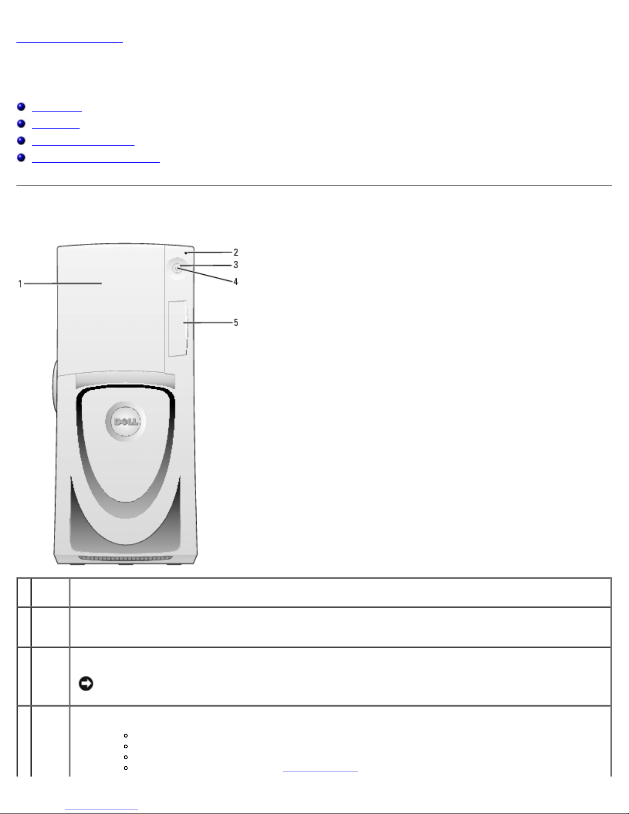
Front View
1 drive
door
2 hard-
drive
light
3 power
button
4 power
light
file:///T|/htdocs/systems/ws670/EN/ug_en/abtmetro.htm[3/20/2013 9:31:44 AM]
Open the drive door to access the optional floppy drive and CD/DVD drives.
The hard-drive light is on when the computer reads data from or writes data to the hard drive. The light might
also be on when a device such as your CD player is operating.
Press this button to turn on the computer.
NOTICE: To avoid losing data, do not use the power button to turn off the computer. Instead, perform a
Microsoft® Windows® shutdown.
The power light illuminates and blinks or remains solid to indicate different states:
No light — The computer is turned off.
Steady green — The computer is in a normal operating state.
Blinking green — The computer is in a power-saving state.
Blinking or solid yellow — See "Power Problems."
Page 12
Your Dell Precision™ 670 Computer: Dell Precision Workstation 470 and 670 Computers User's Guide
6 diagnostic Use the lights to help you troubleshoot a computer problem based on the diagnostic code. For more
To exit from a power-saving state, press the power button or use the keyboard or the mouse if it is configured
as a wake device in the Windows Device Manager. For more information about sleep states and exiting from a
power-saving state, see "Power Management
."
" for a description of light codes that can help you troubleshoot problems with your
5 front-
panel
door
See "Diagnostic Lights
computer.
Open the door to use the front-panel connectors and view the diagnostic lights.
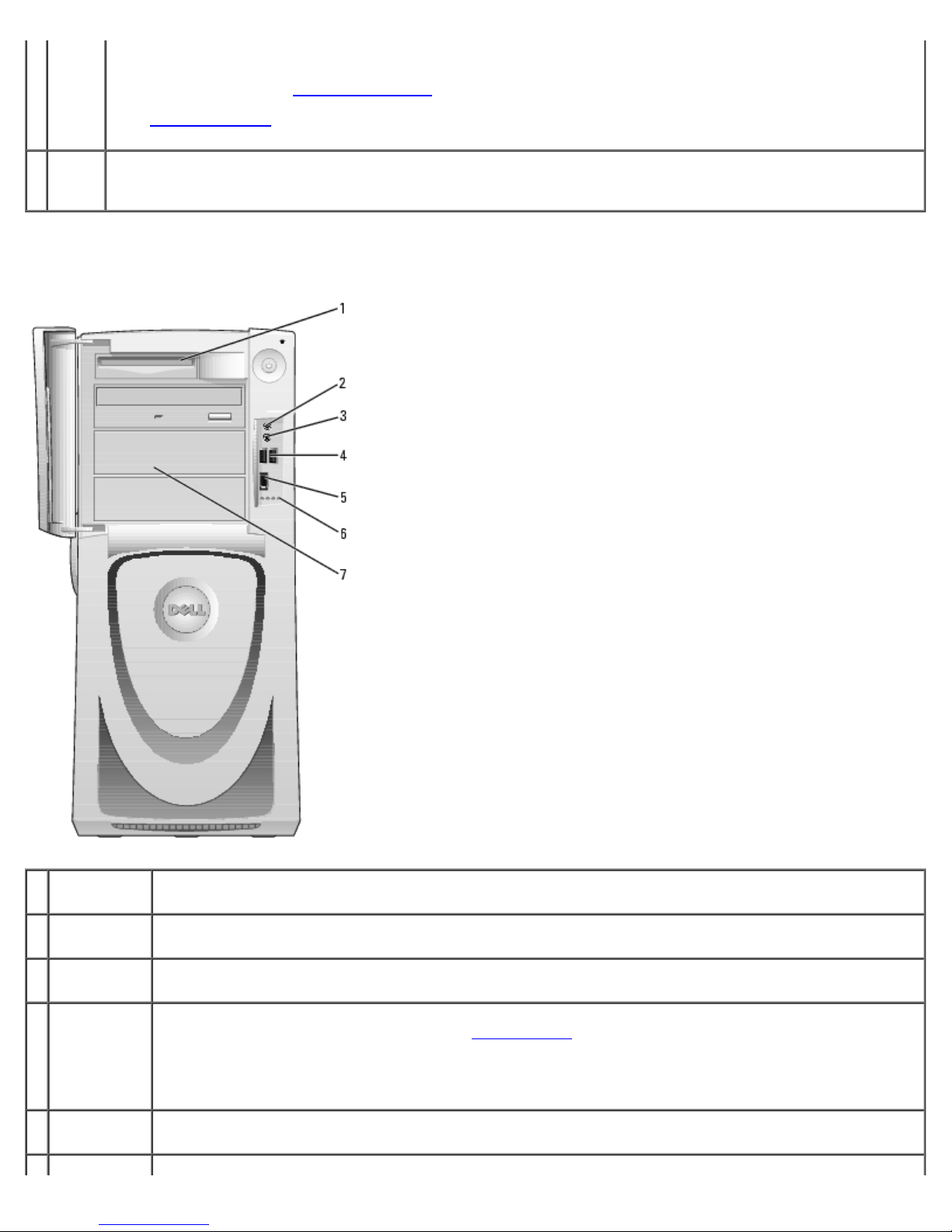
Front View (Doors Open)
1 floppy drive
(optional)
2 headphone
connector
3 microphone
connector
4 USB 2.0
connectors
(2)
5 IEEE 1394a
connector
file:///T|/htdocs/systems/ws670/EN/ug_en/abtmetro.htm[3/20/2013 9:31:44 AM]
Access the optional floppy drive.
Attach headphones.
Attach a microphone.
Use the front USB connectors for devices that you connect occasionally, such as flash memory key or
cameras, or for bootable USB devices (see "System Setup
device).
It is recommended that you use the back USB connectors for devices that typically remain connected, such
as printers and keyboards.
Attach high-speed serial multimedia devices, such as a digital video camera.
" for more information on booting to a USB
Page 13
Your Dell Precision™ 670 Computer: Dell Precision Workstation 470 and 670 Computers User's Guide
lights (4) information, see "Diagnostic Lights."
7 externally
accessible
drives
Access additional drives, such as a CD or DVD drive. Drive arrangement varies on computer configuration.
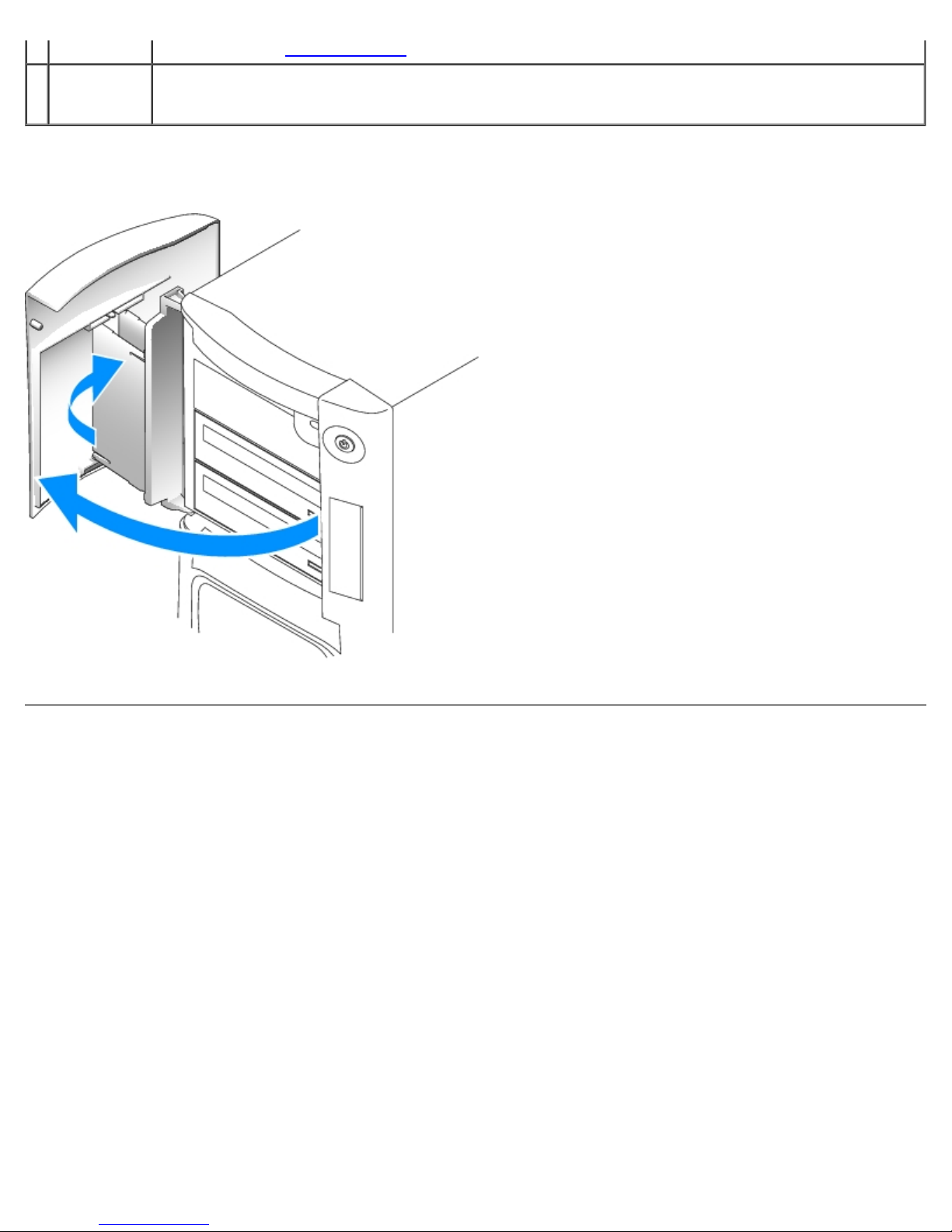
Opening the Drive Door
Back View
file:///T|/htdocs/systems/ws670/EN/ug_en/abtmetro.htm[3/20/2013 9:31:44 AM]
Page 14
Your Dell Precision™ 670 Computer: Dell Precision Workstation 470 and 670 Computers User's Guide
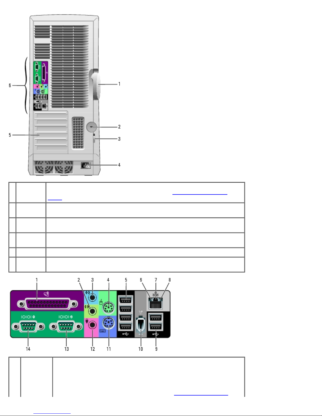
1 cover
latch
release
2 security
To open the computer, lay the computer on its side with the cover latch release
at the top and then push the latch to the left. See "Opening the Computer
Cover."
Use a security cable with the slot to help secure your computer.
cable slot
3 padlock
Insert a padlock to lock the computer cover.
ring
4 power
Insert the power cable.
connector
5 card slots Access connectors for any installed cards.
6 back panel
Plug serial, USB, and other devices into the appropriate connectors.
connectors
1 parallel
connector
Connect a parallel device, such as a printer, to the parallel connector. If you
have a USB printer, plug it into a USB connector.
NOTE: The integrated parallel connector is automatically disabled if the
computer detects an installed card containing a parallel connector configured
to the same address. For more information, see "System Setup Options
file:///T|/htdocs/systems/ws670/EN/ug_en/abtmetro.htm[3/20/2013 9:31:44 AM]
."
Page 15
Your Dell Precision™ 670 Computer: Dell Precision Workstation 470 and 670 Computers User's Guide
2 line-out
connector
3 line-in
connector
4 mouse
connector
5 USB 2.0
connectors
(4)
6 link
integrity
light
Use the green line-out connector to attach headphones and most speakers
with integrated amplifiers.
On computers with a sound card, use the connector on the card.
Use the blue line-in connector to attach a record/playback device such as a
cassette player, CD player, or VCR.
On computers with a sound card, use the connector on the card.
Plug a standard mouse into the green mouse connector. Turn off the
computer and any attached devices before you connect a mouse to the
computer. If you have a USB mouse, plug it into a USB connector.
If your computer is running the Microsoft Windows XP operating system, the
necessary mouse drivers have been installed on your hard drive.
Use the back USB connectors for devices that typically remain connected,
such as printers and keyboards.
It is recommended that you use the front USB connectors for devices that you
connect occasionally, such as flash memory key or cameras, or for bootable
USB devices.
Green — A good connection exists between a 10-Mbps network and
the computer.
Orange — A good connection exists between a 100-Mbps network and
the computer.
Yellow — A good connection exists between a 1000-Mbps (or 1-Gbps)
network and the computer.
Off — The computer is not detecting a physical connection to the
network.
7 network
adapter
connector
8 network
activity
light
9 USB 2.0
connectors
(2)
10 IEEE 1394a
connector
11 keyboard
connector
To attach your computer to a network or broadband device, connect one end
of a network cable to either a network jack or your network or broadband
device. Connect the other end of the network cable to the network adapter
connector on your computer. A click indicates that the network cable has
been securely attached.
NOTE: Do not plug a telephone cable into the network connector.
On computers with a network connector card, use the connector on the card.
It is recommended that you use Category 5 wiring and connectors for your
network. If you must use Category 3 wiring, force the network speed to 10
Mbps to ensure reliable operation.
Flashes a yellow light when the computer is transmitting or receiving network
data. A high volume of network traffic may make this light appear to be in a
steady "on" state.
Use the back USB connectors for devices that typically remain connected,
such as printers and keyboards.
It is recommended that you use the front USB connectors for devices that you
connect occasionally, such as flash memory key or cameras, or for bootable
USB devices.
Attach high-speed serial multimedia devices, such as a digital video camera.
If you have a standard keyboard, plug it into the purple keyboard connector.
If you have a USB keyboard, plug it into a USB connector.
12 microphone
connector
Use the pink microphone connector to attach a personal computer
microphone for voice or musical input into a sound or telephony program.
On computers with a sound card, the microphone connector is on the card.
13,14serial
connectors
file:///T|/htdocs/systems/ws670/EN/ug_en/abtmetro.htm[3/20/2013 9:31:44 AM]
Connect a serial device, such as a handheld device, to the serial port. The
default designations are COM1 for serial connector 1 and COM2 for serial
Page 16
Your Dell Precision™ 670 Computer: Dell Precision Workstation 470 and 670 Computers User's Guide
connector 2.
For more information, see "System Setup Options."
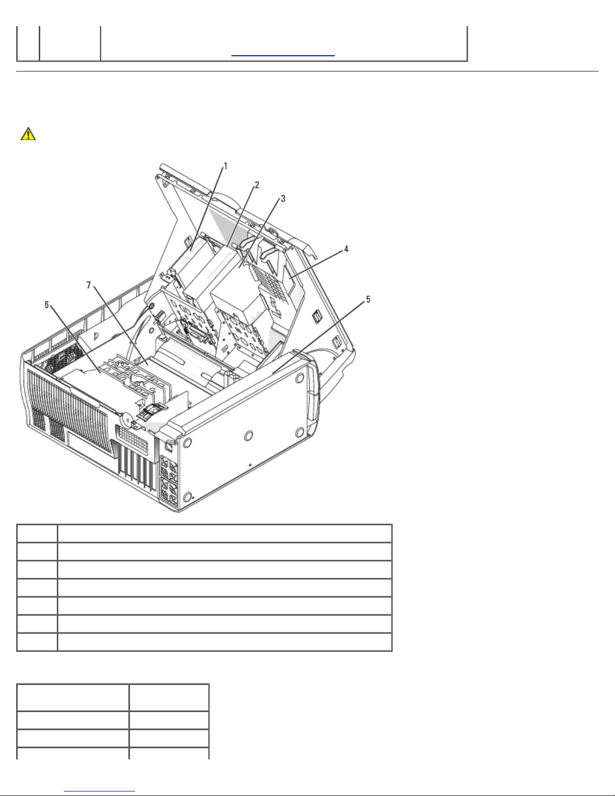
Inside Your Computer
CAUTION: Before you begin any of the procedures in this section, follow the safety instructions located in
the Product Information Guide.
1 floppy drive (optional)
2 CD/DVD drive
3 hard drive shroud
4 card cage/video fan
5 power supply
6 processor shroud/fan
7 system board
Cable Colors
Device Color
Hard drive Blue cables
Floppy drive (optional) Black pull-tab
file:///T|/htdocs/systems/ws670/EN/ug_en/abtmetro.htm[3/20/2013 9:31:44 AM]
Page 17
Your Dell Precision™ 670 Computer: Dell Precision Workstation 470 and 670 Computers User's Guide
CD/DVD drive Orange pull-tab
I/O panel Yellow pull-tab
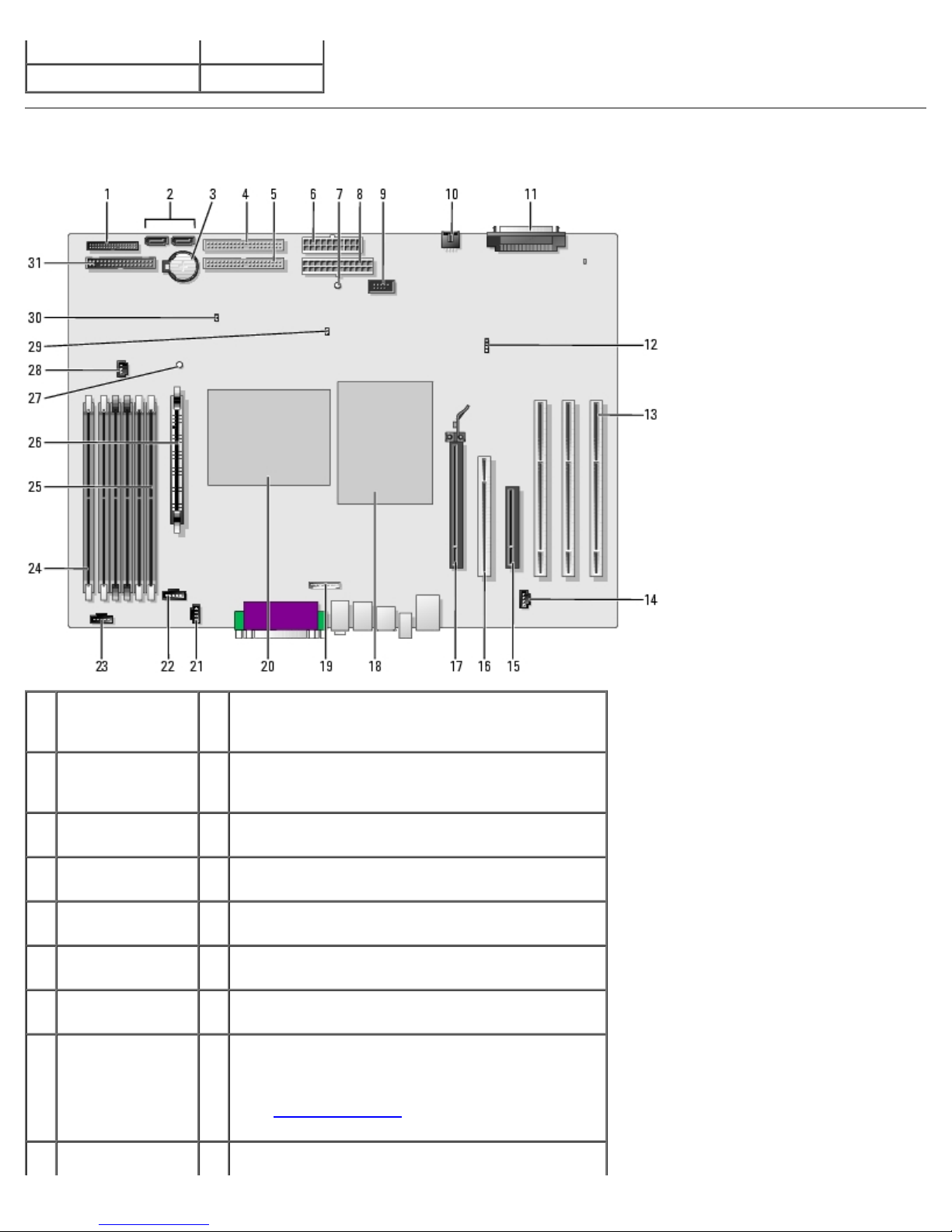
System Board Components
1 front-panel
connector
(PANEL)
2 SATA connectors
(2) (SATA_0 and
SATA_1)
3 battery socket
(BATTERY)
4 CD/DVD drive
connector (IDE1)
5 CD/DVD drive
connector (IDE2)
6 power connector
(POWER_2)
7 standby power
light (AUX_PWR)
8 power connector
(POWER_1)
9 IEEE 1394a 25 memory module connector (DIMM_6)
17 PCI Express x16 connector
18 processor (CPU_0)
19 front-panel audio cable connector (FRONTAUDIO)
20 processor (CPU_1)
21 CD-drive audio cable connector (CD_IN)
22 processor fan connector (FAN_P0)
23 processor fan connector (FAN_P1)
24 memory module connector (DIMM _1)
The connectors are labeled DIMM_1 through
DIMM_6 with DIMM_1 at the edge of the board.
See "Memory Overview
installing memory.
" for instructions on
file:///T|/htdocs/systems/ws670/EN/ug_en/abtmetro.htm[3/20/2013 9:31:44 AM]
Page 18
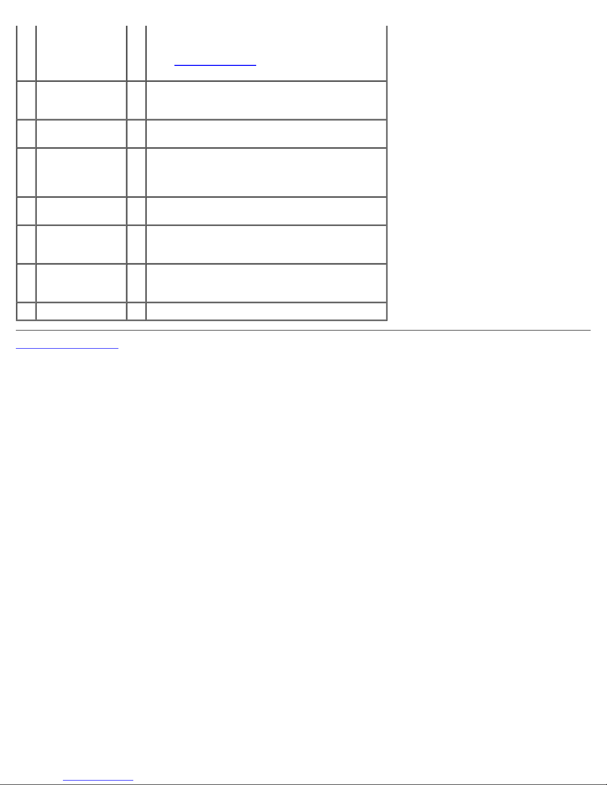
Your Dell Precision™ 670 Computer: Dell Precision Workstation 470 and 670 Computers User's Guide
connector
(FP1394a)
10 card fan
26 Voltage Regulator Module (VRM)
connector
(FAN_CCAG)
11 SCSI connector
27 suspend-to-RAM light (STR_LED)
(SCSI)
12 auxiliary hard-
28 memory fan connector (FAN_MEM)
drive activity light
connector
(AUX_LED)
13 PCIX card
29 password jumper (PSWD)
connectors
14 telephony
30 RTC reset jumper (RTCRST)
connector
(MODEM)
15 PCI Express x8
31 floppy-drive connector (DISKETTE)
connector (runs
at x4 only)
16 PCI connector
The connectors are labeled DIMM_1 through
DIMM_6 with DIMM_6 closest to the processor.
See "Memory Overview
" for instructions on
installing memory.
Back to Contents Page
file:///T|/htdocs/systems/ws670/EN/ug_en/abtmetro.htm[3/20/2013 9:31:44 AM]
Page 19
Your Dell Precision™ 470 Computer: Dell Precision Workstation 470 and 670 Computers User's Guide
Back to Contents Page
Your Dell Precision™ 470 Computer
Dell Precision™ Workstation 470 and 670 Computers User's Guide
Front View
Back View
Inside Your Computer
System Board Components
Front View
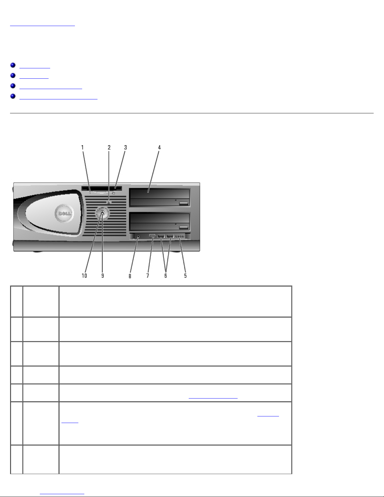
1 floppy-
drive
activity
light
2 hard-drive
activity
light
3 floppy
drive
(optional)
4 CD/DVD
drive(s)
5 diagnostic
lights (4)
6 USB 2.0
connectors
(2)
7 IEEE
1394a
connector
The floppy drive light is on when the computer reads data from or writes data
to the optional floppy drive. Wait until this light turns off before you remove
the floppy disk from the drive.
The hard drive light is on when the computer reads data from or writes data to
the hard drive. The light might also be on when a device such as your CD
player is operating.
Access the optional floppy drive.
Access additional drives, such as a CD or DVD drive. Drive arrangement varies
on computer configuration.
Use the lights to help you troubleshoot a computer problem based on the
diagnostic code. For more information, see "Diagnostic Lights
Use the front USB connectors for devices that you connect occasionally, such
as flash memory key or cameras, or for bootable USB devices (see "System
Setup" for more information on booting to a USB device).
It is recommended that you use the back USB connectors for devices that
typically remain connected, such as printers and keyboards.
Attach high-speed serial multimedia devices, such as digital video cameras.
NOTE: This connector is available if you purchase an add-in IEEE 1394a card.
."
file:///T|/htdocs/systems/ws670/EN/ug_en/abtdev.htm[3/20/2013 9:31:45 AM]
Page 20
Your Dell Precision™ 470 Computer: Dell Precision Workstation 470 and 670 Computers User's Guide
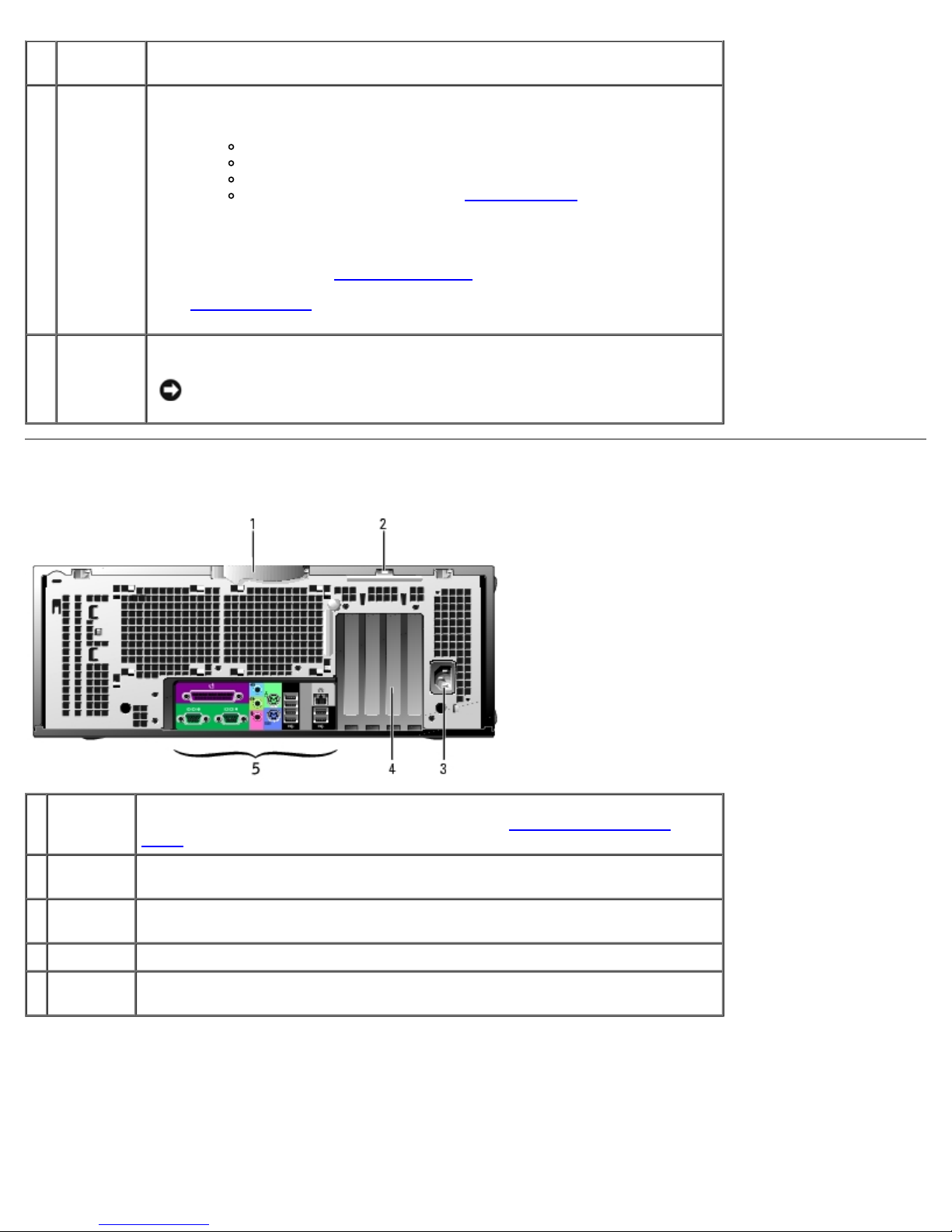
8 headphone
connector
9 power
light
10 power
button
Use the headphone connector to attach headphones and most kinds of
speakers.
The power light illuminates and blinks or remains solid to indicate different
states:
To exit from a power-saving state, press the power button or use the keyboard
or the mouse if it is configured as a wake device in the Windows Device
Manager. For more information about sleep states and how to exit from a
power-saving state, see "Power Management
See "Diagnostic Lights
troubleshoot problems with your computer.
Press to turn on the computer.
Back View
No light — The computer is turned off.
Steady green — The computer is in a normal operating state.
Blinking green — The computer is in a power-saving state.
Blinking or solid yellow— See "Power Problems."
."
" for a description of light codes that can help you
NOTICE: To avoid losing data, do not use the power button to turn off
the computer. Instead, perform an operating system shutdown.
1 cover
latch
release
2 padlock
ring
3 power
connector
4 card slots Access connectors for any installed cards.
5 back panel
connectors
file:///T|/htdocs/systems/ws670/EN/ug_en/abtdev.htm[3/20/2013 9:31:45 AM]
To open the computer, lay the computer on its side with the cover latch release
at the top and then push the latch to the left (see "Opening the Computer
Cover").
Insert a padlock to lock the computer cover.
Insert the power cable.
Plug serial, USB, and other devices into the appropriate connectors.
Page 21
Your Dell Precision™ 470 Computer: Dell Precision Workstation 470 and 670 Computers User's Guide
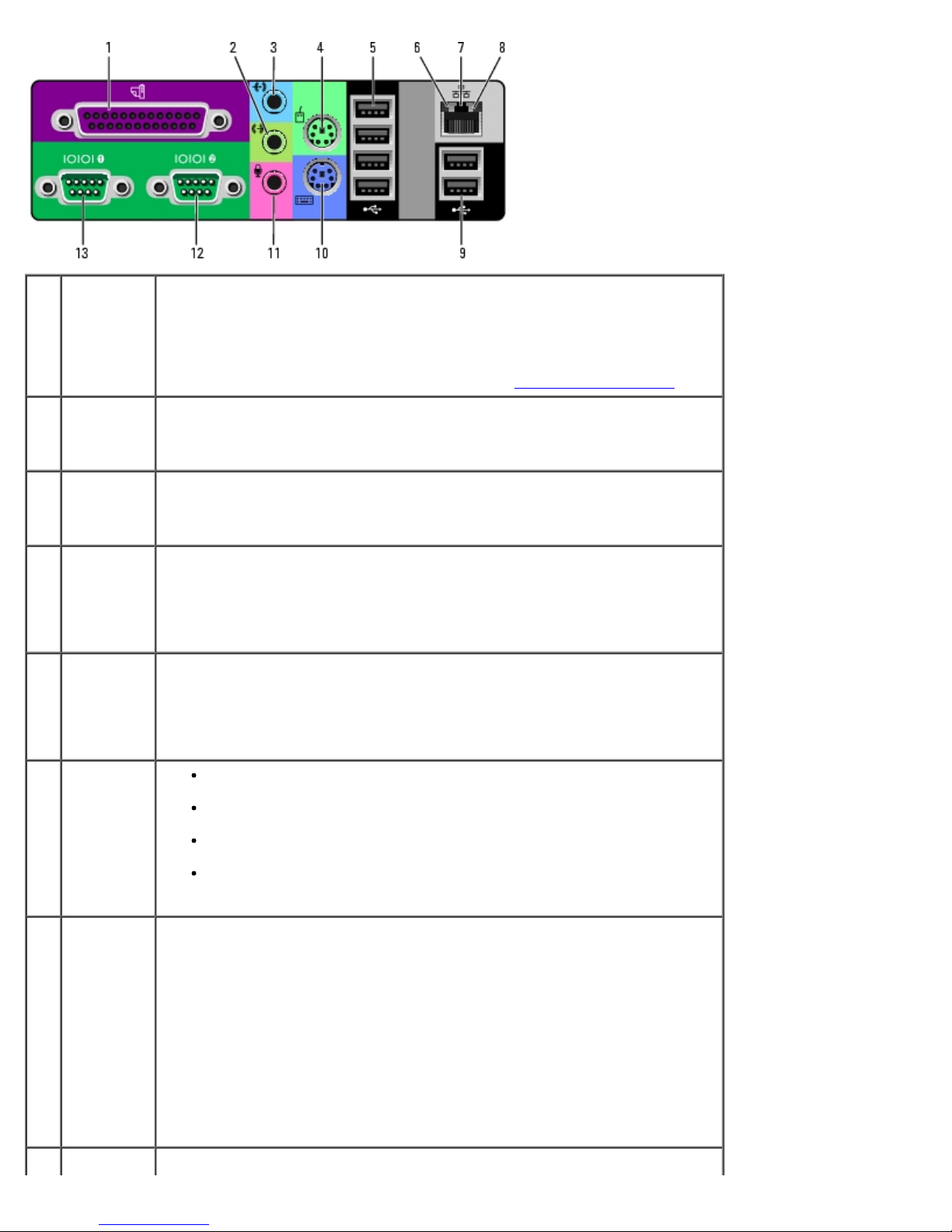
1 parallel
connector
2 line-in
connector
3 line-out
connector
4 mouse
connector
5 USB 2.0
connectors
(4)
Connect a parallel device, such as a printer, to the parallel connector. If you
have a USB printer, plug it into a USB connector.
NOTE: The integrated parallel connector is automatically disabled if the
computer detects an installed card containing a parallel connector configured
to the same address. For more information, see "System Setup Options
."
Use the blue line-in connector to attach a record/playback device such as a
cassette player, CD player, or VCR.
On computers with a sound card, use the connector on the card.
Use the green line-out connector to attach headphones and most speakers
with integrated amplifiers.
On computers with a sound card, use the connector on the card.
Plug a standard mouse into the green mouse connector. Turn off the
computer and any attached devices before you connect a mouse to the
computer. If you have a USB mouse, plug it into a USB connector.
If your computer is running the Microsoft® Windows® XP operating system,
the necessary mouse drivers have been installed on your hard drive.
Use the back USB connectors for devices that typically remain connected,
such as printers and keyboards.
It is recommended that you use the front USB connectors for devices that you
connect occasionally, such as flash memory key or cameras, or for bootable
USB devices.
6 link
integrity
light
Green — A good connection exists between a 10-Mbps network and
the computer.
Orange — A good connection exists between a 100-Mbps network and
the computer.
Yellow — A good connection exists between a 1000-Mbps (or 1-Gbps)
network and the computer.
Off — The computer is not detecting a physical connection to the
network.
7 network
adapter
connector
To attach your computer to a network or broadband device, connect one end
of a network cable to either a network jack or your network or broadband
device. Connect the other end of the network cable to the network adapter
connector on your computer. A click indicates that the network cable has
been securely attached.
NOTE: Do not plug a telephone cable into the network connector.
On computers with a network connector card, use the connector on the card.
It is recommended that you use Category 5 wiring and connectors for your
network. If you must use Category 3 wiring, force the network speed to 10
Mbps to ensure reliable operation.
8 network Flashes a yellow light when the computer is transmitting or receiving network
file:///T|/htdocs/systems/ws670/EN/ug_en/abtdev.htm[3/20/2013 9:31:45 AM]
Page 22
Your Dell Precision™ 470 Computer: Dell Precision Workstation 470 and 670 Computers User's Guide
activity
data. A high volume of network traffic may make this light appear to be in a
light
9 USB 2.0
connectors
(2)
10 keyboard
connector
11 microphone
connector
12,13serial
connectors
steady "on" state.
Use the back USB connectors for devices that typically remain connected,
such as printers and keyboards.
It is recommended that you use the front USB connectors for devices that you
connect occasionally, such as flash memory key or cameras, or for bootable
USB devices.
If you have a standard keyboard, plug it into the purple keyboard connector.
If you have a USB keyboard, plug it into a USB connector.
Use the pink microphone connector to attach a personal computer
microphone for voice or musical input into a sound or telephony program.
On computers with a sound card, the microphone connector is on the card.
Connect a serial device, such as a handheld device, to the serial port. The
default designations are COM1 for serial connector 1 and COM2 for serial
connector 2.
For more information, see "System Setup Options
."
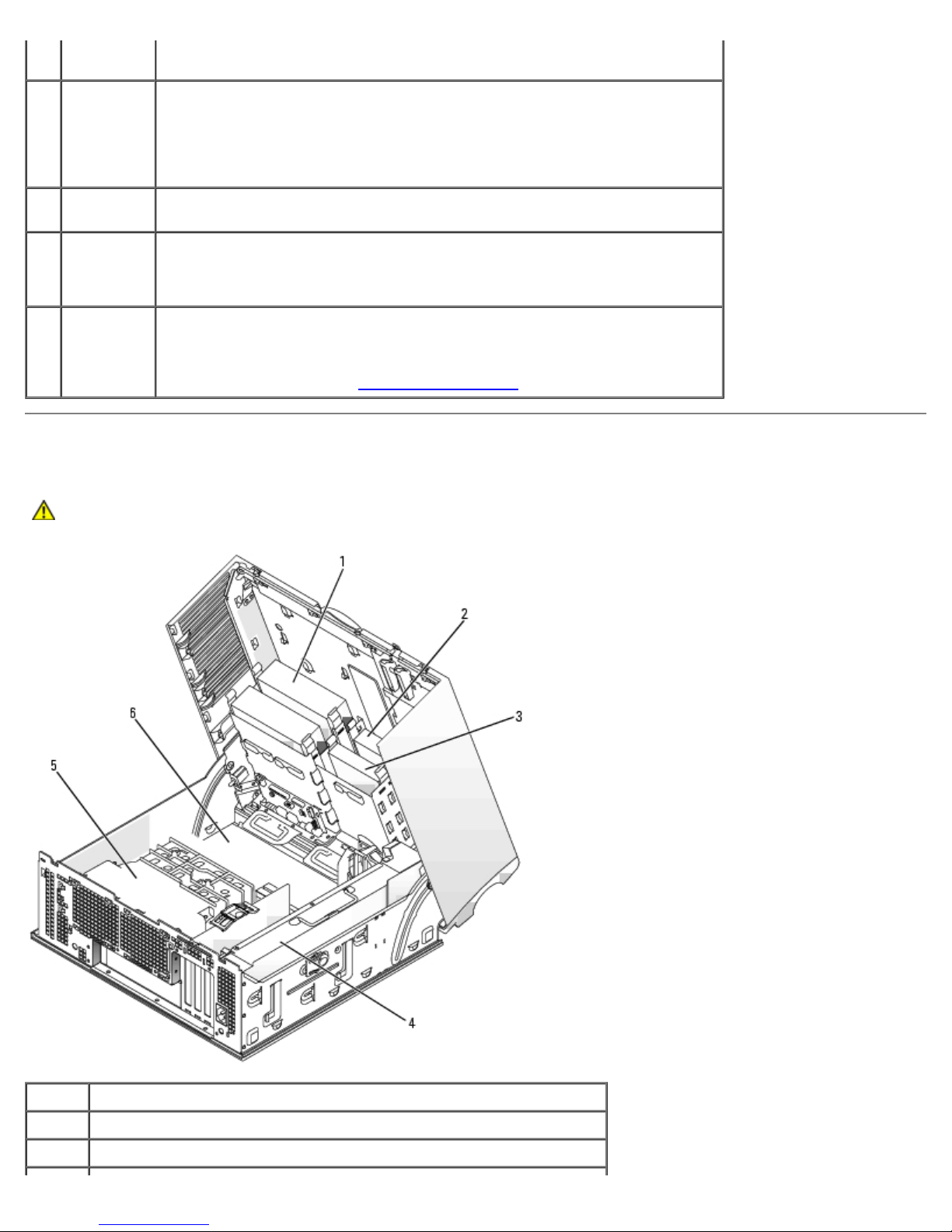
Inside Your Computer
CAUTION: Before you begin any of the procedures in this section, follow the safety instructions located in
the Product Information Guide.
1 CD/DVD drive
2 floppy drive (optional)
3 hard drive
file:///T|/htdocs/systems/ws670/EN/ug_en/abtdev.htm[3/20/2013 9:31:45 AM]
Page 23
Your Dell Precision™ 470 Computer: Dell Precision Workstation 470 and 670 Computers User's Guide
4 power supply
5 airflow shroud
6 system board
Cable Colors
Device Color
SATA hard drive Blue cable
Floppy drive (optional) Black pull-tab
CD/DVD drive Orange pull-tab
I/O panel Yellow pull-tab
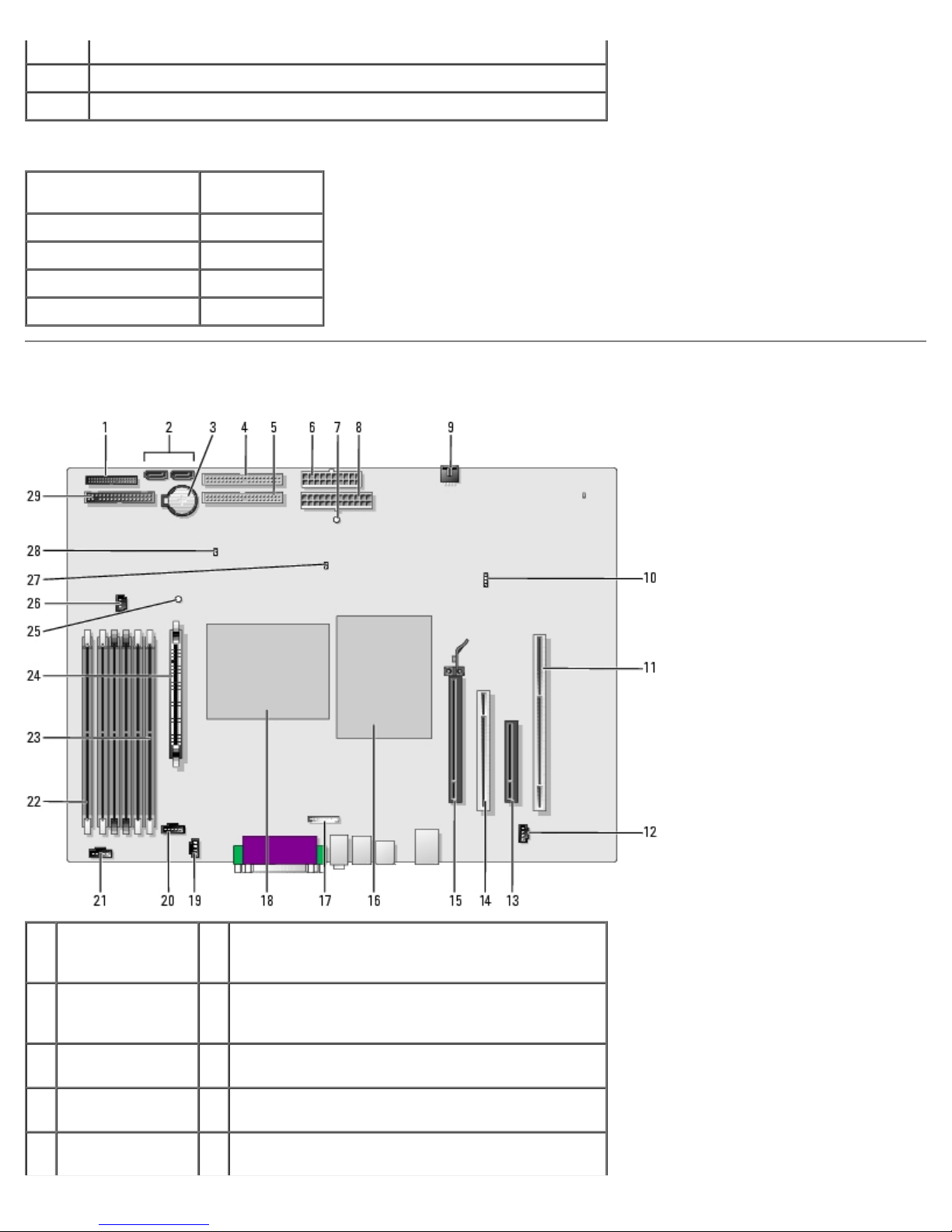
System Board Components
1 front-panel
connector
(PANEL)
2 SATA connectors
(2) (SATA_0 and
SATA_1)
3 battery socket
(BATTERY)
4 CD/DVD drive
connector (IDE1)
5 CD/DVD drive
connector (IDE2)
file:///T|/htdocs/systems/ws670/EN/ug_en/abtdev.htm[3/20/2013 9:31:45 AM]
16 processor (CPU_0)
17 front-panel audio cable connector (FRONTAUDIO)
18 processor (CPU_1)
19 CD-drive audio cable connector (CD_IN)
20 processor fan connector (FAN_P0)
Page 24
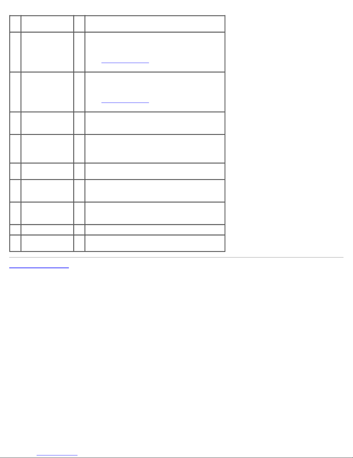
Your Dell Precision™ 470 Computer: Dell Precision Workstation 470 and 670 Computers User's Guide
5 power connector
(POWER2)
7 power connector
(POWER1)
8 standby power
light (AUX_PWR)
9 card fan
connector
(FAN_CCAG)
10 auxiliary hard-
drive activity light
connector
(AUX_LED)
11 PCIX card
connector
12 telephony
connector
(MODEM)
21 processor fan connector (FAN_P1)
22 memory module connector (DIMM _1)
The connectors are labeled DIMM_1 through
DIMM_6 with DIMM_1 at the edge of the board.
See "Memory Overview
" for instructions on
installing memory.
23 memory module connector (DIMM_6)
The connectors are labeled DIMM_1 through
DIMM_6 with DIMM_6 closest to the processor.
See "Memory Overview
" for instructions on
installing memory.
24 Voltage Regulator Module (VRM)
25 suspend-to-RAM light (STR_LED)
26 memory fan connector (FAN_MEM)
27 password jumper (PSWD)
13 PCI Express x8
28 RTC reset jumper (RTCRST)
connector (runs
at x4 only)
14 PCI connector 29 floppy-drive connector (DISKETTE)
15 PCI Express x16
connector
Back to Contents Page
file:///T|/htdocs/systems/ws670/EN/ug_en/abtdev.htm[3/20/2013 9:31:45 AM]
Page 25
Advanced Features: Dell Precision Workstation 470 and 670 Computers User's Guide
Back to Contents Page
Advanced Features
Dell Precision™ Workstation 470 and 670 Computers User's Guide
LegacySelect Technology Control
Manageability
Security
Password Protection
System Setup
Clearing Forgotten Passwords
Clearing CMOS Settings
Hyper-Threading
IEEE 1394a
U320 SCSI Controller
Power Management
Copying CDs and DVDs
LegacySelect Technology Control
LegacySelect technology control offers legacy-full, legacy-reduced, or legacy-free solutions based on common platforms,
hard-drive images, and help desk procedures. Control is provided to the administrator through system setup, Dell
OpenManage™ IT Assistant, or Dell™ custom factory integration.
LegacySelect allows administrators to electronically activate or deactivate connectors and media devices that include serial
and USB connectors, a parallel connector, a floppy drive, PCI slots, and a PS/2 mouse. Connectors and media devices that are
deactivated make resources available. You must restart the computer to effect the changes.
Manageability
Alert Standard Format
ASF is a DMTF management standard that specifies "pre-operating system" or "operating system-absent" alerting techniques.
The standard is designed to generate an alert on potential security and fault conditions when the operating system is in a
sleep state or the computer is powered down. ASF is designed to supersede previous operating system-absent alerting
technologies.
Your computer supports the ASF alerts and remote capabilities described in the following table.
Alert Description
Chassis: Chassis Intrusion – Physical Security
Violation/Chassis Intrusion – Physical Security
Violation Event Cleared
BIOS: Corrupt BIOS/Corrupt BIOS Cleared
Boot: Failure to Boot to BIOS
Password: System Password Violation
CPU: CPU DOA Alert/CPU DOA Alert Cleared
Heartbeats: Entity Presence
Temperature: Generic Critical Temperature
Problem/Generic Critical Temperature Problem Cleared
The computer chassis has been opened or the chassis
intrusion alert has been cleared.
The BIOS has been corrupted or the BIOS corruption
has been resolved.
The BIOS did not complete loading upon initiation.
The system password is invalid (alert occurs after three
failed attempts).
The processor is not functioning.
Periodic heartbeats have been transmitted to verify
system presence.
The computer temperature is out of limits or the
computer temperature problem has been resolved.
file:///T|/htdocs/systems/ws670/EN/ug_en/advfeat.htm[3/20/2013 9:31:46 AM]
Page 26

Advanced Features: Dell Precision Workstation 470 and 670 Computers User's Guide
Voltage: Generic Critical Voltage Problem/Generic
The voltage from integrated voltage regulators is out of
Critical Voltage Problem Cleared
Power Supply: Critical Power Supply Problem/
Critical Power Supply Problem Cleared
Cooling Device: Generic Critical Fan Failure/Generic
Critical Fan Failure Cleared
Connectivity: Ethernet Connectivity Enabled/
Ethernet Connectivity Disabled
For more information about Dell's ASF implementation, see the ASF User's Guide and the ASF Administrator's Guide, which
are available on the Dell Support website at support.dell.com.
limits or the voltage problem has been resolved.
The computer power supply voltage is out of limits or
the computer power supply voltage problem has been
resolved.
The fan speed (rpm) is out of limits or the fan speed
(rpm) problem has been resolved.
The Ethernet connectivity is enabled or the Ethernet
connectivity is disabled.
Dell OpenManage IT Assistant
IT Assistant configures, manages, and monitors computers and other devices on a corporate network. IT Assistant manages
assets, configurations, events (alerts), and security for computers equipped with industry-standard management software. It
supports instrumentation that conforms to SNMP, DMI, and CIM industry standards.
Dell OpenManage Client instrumentation, which is based on DMI and CIM, is available for your computer. For information on
IT Assistant, see the Dell OpenManage IT Assistant User's Guide available on the Dell Support website at support.dell.com.
Dell OpenManage Client Instrumentation
Dell OpenManage Client Instrumentation is software that enables remote management programs such as IT Assistant to do
the following:
Access information about your computer, such as how many it has and what operating system it is running.
Monitor the status of your computer, such as listening for thermal alerts from temperature probes or hard-drive failure
alerts from storage devices.
Change the state of your computer, such as updating its BIOS or shutting it down remotely.
A managed system is one that has Dell OpenManage Client Instrumentation set up on a network that uses IT Assistant. For
information about Dell OpenManage Client Instrumentation, see the Dell OpenManage Client Instrumentation User's Guide
available on the Dell Support website at support.dell.com.
Security
Chassis Intrusion Detection
NOTE: When the admin password is enabled, you must know the admin password before you can reset the Chassis
Intrusion setting.
This feature detects that the chassis was opened and alerts the user. To change the Chassis Intrusion setting:
1. Enter system setup
2. Press the down-arrow key to move to the System Security option Chassis Intrusion field.
3. Press <Enter> to access the menu.
4. Use the left- and right-arrow key to select an option setting.
file:///T|/htdocs/systems/ws670/EN/ug_en/advfeat.htm[3/20/2013 9:31:46 AM]
.
Page 27

Advanced Features: Dell Precision Workstation 470 and 670 Computers User's Guide
5. Exit system setup.
Option Settings
Enabled — If the computer cover is opened, the setting changes to Detected, and the following alert message
displays during the boot routine at the next computer start-up:
Alert! Cover was previously removed.
To reset the Detected setting, enter system setup
to select Reset, and then choose Enabled, Enabled-Silent, or Disabled.
Enabled-Silent (default) — If the computer cover is opened, the setting changes to Detected. No alert message
appears during the boot sequence at the next computer start-up.
Disabled — No intrusion monitoring occurs and no messages appear.
. In the Chassis Intrusion option, press the left- or right-arrow key
Padlock Ring and Security Cable Slot
Use one of the following methods to secure your computer:
Use a padlock alone or a padlock and looped security cable with the padlock ring. (For the location of the padlock on
the Dell Precision 670 computer, see "Inside Your Computer
Computer.") A padlock alone prevents the computer from being opened.
A security cable looped around a stationary object is used in conjunction with a padlock to prevent unauthorized
movement of the computer.
Attach a commercially available antitheft device to the security cable slot on the back of the computer.
NOTE: Before you purchase an antitheft device, make sure that it works with the security cable slot on your computer.
" and for the Dell Precision 470 computer, see "Inside Your
Antitheft devices usually include a segment of metal-stranded cable with an attached locking device and key. The
documentation that comes with the device contains instructions for installing it.
Password Protection
NOTICE: Although passwords provide security for the data on your computer, they are not foolproof. If your data
requires more security, it is your responsibility to obtain and use additional forms of protection, such as data
encryption programs.
System Password
NOTICE: If you leave your computer running and unattended without having a system password assigned, or if you
leave your computer unlocked so that someone can disable the password by changing a jumper setting, anyone can
access the data stored on your hard drive.
Option Settings
You cannot change or enter a new system password if the following option is displayed:
Disabled — The system password is disabled by a jumper setting on the system board.
file:///T|/htdocs/systems/ws670/EN/ug_en/advfeat.htm[3/20/2013 9:31:46 AM]
Page 28

Advanced Features: Dell Precision Workstation 470 and 670 Computers User's Guide
You can only assign a system password when one of the two following options is displayed:
Set — A system password is assigned.
Not Set — No system password is assigned and the password jumper on the system board is in the enabled position
(the default).
Assigning a System Password
To escape from the field without assigning a system password, press <Tab> or the <Shift><Tab> key combination to move
to another field, or press <Esc> at any time before you complete step 5.
1. Enter system setup
2. Highlight System Password, and then press <Enter>.
3. Type your new system password.
You can use up to 32 characters. To erase a character when entering your password, press <Backspace> or the leftarrow key. The password is not case sensitive.
Certain key combinations are not valid. If you enter one of these combinations, the cursor does not move.
As you press each character key (or the spacebar for a blank space), a placeholder appears in the field.
4. Press <Enter>.
If the new system password is less than 32 characters, the whole field fills with placeholders. Then the option heading
changes to Confirm Password, followed by another empty 32-character field in square brackets.
5. To confirm your password, type it a second time and press <Enter>.
The password setting changes to Set.
6. Exit system setup.
Password protection takes effect when you restart the computer.
and verify that Password Changes is set to Unlocked.
Typing Your System Password
When you start or restart your computer, the following prompt appears on the screen.
Type the system password and press <Enter>.
Enter password:
If you have assigned an admin password, the computer accepts your admin password as an alternate system password.
If you type a wrong or incomplete system password, the following message appears on the screen:
** Incorrect password. **
If you again type an incorrect or incomplete system password, the same message appears on the screen. The third and
subsequent times you type an incorrect or incomplete system password, the computer displays the following message:
** Incorrect password. **
Number of unsuccessful password attempts: 3
System halted! Must power down.
Even after your computer is turned off and on, the previous message is displayed each time you type an incorrect or
incomplete system password.
NOTE: You can use Password Changes in conjunction with System Password and Admin Password to further
file:///T|/htdocs/systems/ws670/EN/ug_en/advfeat.htm[3/20/2013 9:31:46 AM]
Page 29

Advanced Features: Dell Precision Workstation 470 and 670 Computers User's Guide
protect your computer from unauthorized changes.
Changing or Deleting an Existing System Password
To change a system password:
1. Enter system setup
2. Highlight System Password and press <Enter>.
3. Enter your old password and enter the new password at the New Password and Confirm New Password prompts.
To delete a system password:
1. Enter system setup
2. Highlight System Password and press <Enter>.
3. Enter your old password and enter a blank password at the New Password and Confirm New Password prompts.
The setting changes to Not Set.
4. If you want to assign a new admin password, see "Assigning a System Password
.
.
."
Admin Password
Option Settings
Set — Does not allow assignment of admin passwords; users must enter an admin password to make changes to
system setup.
Not Set — Allows assignment of admin passwords; password feature is enabled but no password is assigned.
Disabled — The admin password is disabled by a jumper setting on the system board.
Assigning an Admin Password
The admin password can be the same as the system password.
NOTE: If the two passwords are different, the admin password can be used as an alternate system password.
However, the system password cannot be used in place of the admin password.
1. Enter system setup
2. Highlight Admin Password and press <Enter>.
The computer prompts you to type and verify the password. If a character is not permitted, the computer emits a
beep.
3. Type and then verify the password.
After you verify the password, the Admin Password setting changes to Set. The next time you enter system setup,
the computer prompts you for the admin password.
and verify that Admin Password is set to Not Set.
4. Exit system setup.
file:///T|/htdocs/systems/ws670/EN/ug_en/advfeat.htm[3/20/2013 9:31:46 AM]
Page 30

Advanced Features: Dell Precision Workstation 470 and 670 Computers User's Guide
A change to Admin Password becomes effective immediately (you do not need to restart the computer).
Operating Your Computer With an Admin Password Enabled
When you enter system setup, you can view, but not notify, system setup options. To modify options, go into Unlock Setup
in the Security group and enter the admin password.
NOTE: You can use Password Status in conjunction with Admin Password to protect the system password from
unauthorized changes.
Changing or Deleting an Existing Admin Password
To change the admin password:
1. Enter system setup
2. Highlight Admin Password and press <Enter>.
3. Enter your old password and enter the new password at the New Password and Confirm New Password prompts.
To delete the admin password:
1. Enter system setup
2. Highlight Admin Password and press <Enter>.
3. Enter your old password and enter a blank password at the New Password and Confirm New Password prompts.
The setting changes to Not Set.
.
.
Disabling a Forgotten Password and Setting a New Password
To reset system and/or admin passwords, see "Clearing Forgotten Passwords."
System Setup
Overview
Use system setup as follows:
To change the system configuration information after you add, change, or remove any hardware in your computer
To set or change a user-selectable option such as the user password
To read the current amount of memory or set the type of hard drive installed
Before you use system setup, it is recommended that you write down the system setup screen information for future
reference.
Entering System Setup
1. Turn on (or restart) your computer.
file:///T|/htdocs/systems/ws670/EN/ug_en/advfeat.htm[3/20/2013 9:31:46 AM]
Page 31
Advanced Features: Dell Precision Workstation 470 and 670 Computers User's Guide
2. When the blue DELL™ logo appears, press <F2> immediately.
If you wait too long and the operating system logo appears, continue to wait until you see the Microsoft® Windows®
desktop. Then shut down your computer and try again.
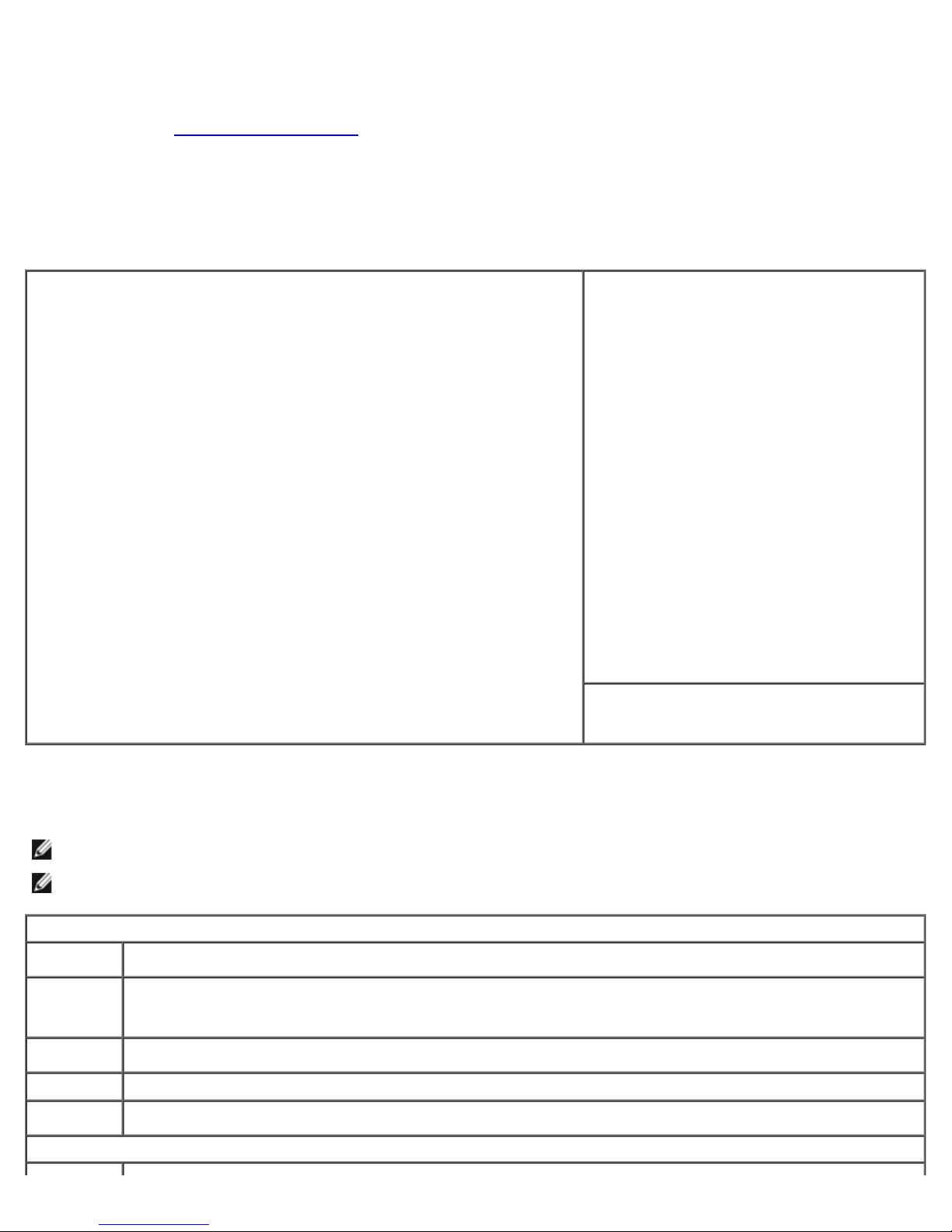
System Setup Screens
The system setup screen displays current or changeable configuration information for your computer. Information on the
screen is divided into three areas: the options list, active options field, and key functions.
Options List — This field appears on the left side of the system setup
window. The field is a scrollable list containing features that define the
configuration of your computer, including installed hardware, power
conservation, and security features.
Scroll up and down the list by using the up- and down-arrow keys. As an
option is highlighted, the Option Field displays more information about
that option and the option's current and available settings.
Option Field — This field contains
information about each option. In this field
you can view your current settings and make
changes to your settings.
Use the left- and right-arrow keys to
highlight an option. Press <Enter> to make
that selection active.
Key Functions — This field appears below
the Option Field and lists keys and their
functions within the active system setup field.
System Setup Options
NOTE: Depending on your computer and installed devices, the items listed in this section may or may not appear.
NOTE: The system setup program defaults are listed under their respective options where applicable.
System
System
Info
Processor
Info
Memory
Info
Date/Time
Boot
Sequence
Drives
file:///T|/htdocs/systems/ws670/EN/ug_en/advfeat.htm[3/20/2013 9:31:46 AM]
Lists the computer name, version number of the BIOS, date of the BIOS, Asset Tag, and Service Tag.
Identifies whether the computer's processor supports Hyper-Threading, and identifies the processor speed,
bus speed, clock speed, EM64T, L2 cache, multiple-core capabilities, number of processors, and processor
type.
Indicates amount of installed memory, computer memory speed, and channel mode (dual or single).
Displays current date and time settings. You can modify these settings.
The computer attempts to boot from the sequence of devices specified in the list on the screen.
Page 32
Advanced Features: Dell Precision Workstation 470 and 670 Computers User's Guide
SCSI
Available on the Dell Precision 670 computer.This field enables and disables the integrated SCSI controller.
Primary
Controller
Diskette
Drive
Enables and disables the floppy drives and sets read permission for the internal floppy drive. Off disables all
floppy drives. Internal enables the internal floppy drive. USB disables the internal floppy drive and enables a
USB drive if the USB controller is enabled and a USB drive is connected. Read Only enables the internal drive
controller and allows the internal floppy drive read-only permission.
Drive 0
Drive 1
Drive 2
Drive 3
Drive 4
Drive 5
SATA
Operation
SMART
Reporting
Identifies the primary hard drive attached to the SATA0 connector on the system board.
Identifies the secondary hard drive attached to the SATA1 connector on the system board.
Identifies the primary hard drive attached to the IDE1 connector on the system board.
Identifies the secondary hard drive attached to the IDE1 connector on the system board.
Identifies the primary hard drive attached to the IDE2 connector on the system board.
Identifies the secondary hard drive attached to the IDE2 connector on the system board.
Configures the operating mode of the integrated hard drive controller.
Control whether hard driver errors for internal SATA and IDE drives are reported during system start-up.
Onboard Devices
Integrated
NIC
(On
default)
Integrated
Audio
You can set the NIC to On (default), Off, On w/ PXE, or On w/ RPL. When the On w/ PXE or On w/ RPL
setting is active (available only for the future boot process), the computer attempts to boot from a network
server. If a boot routine is not available from the network server, the computer attempts to boot from the
next device in the boot sequence list.
Enables or disables the onboard audio controller.
(On
default)
USB
Controller
(On
default)
1394
Controller
(On
default)
LPT Port
Mode
(PS/2
default)
LPT Port
Address
(378H
default)
Serial
Port #1
(Auto
default)
Serial
Port #2
Enables or disables the integrated USB controller. Off disables the controller. On enables the controller. No
Boot enables the controller, but the BIOS will not recognize USB storage devices.
Enables or disables onboard IEEE 1394a controller (for the Dell Precision 670 computer only).
Determines the mode of operating of the internal parallel port. Off disables the port. AT configures the port
for IBM AT compatibility. PS/2 configures the port for IBM PS/2 compatibility. EPP configures the port for the
EPP bidirectional protocol. ECP configures the port for the ECP bidirectional protocol.
NOTE: If you set the LPT Port Mode to ECP, the LPT Port DMA appears in the option menu.
Determines the address that the built-in parallel port uses.
Auto, the default setting, automatically configures a connector to a particular designation (COM1 or COM3).
Auto, the default setting, automatically configures a connector to a particular designation (COM2 or COM4).
(Auto
default)
PS/2 Mouse
Port
Enables or disables the integrated legacy PS/2-compatible mouse controller.
(On
default)
Video
Determines which video controller will become the primary video controller when 2 controllers are available in
file:///T|/htdocs/systems/ws670/EN/ug_en/advfeat.htm[3/20/2013 9:31:46 AM]
Page 33
Advanced Features: Dell Precision Workstation 470 and 670 Computers User's Guide
Video
the system. The default is PEG, the PCI Express Graphics video controller.
(PEG
default)
Performance
CPU Count
Enables the second CPU. This option is only valid in dual processor systems.
(On
default)
Multiple
CPU Core
Specifies whether the processor will have one or two cores enabled. This option is only valid in a system with
one or two dual core processors.
(On
default)
HyperThreading
(Off
Determines whether each physical processor appears as one or two logical processors. The performance of
some programs improves with additional logical processors. On enables Hyper-Threading. Off disables HyperThreading.
default)
SpeedStep
(Off
Specifies whether enhanced SpeedStep technology will be enabled for all supported processor(s) in the
system.
default)
HDD
Acoustic
Mode
Bypass — Your computer does not test or change the current acoustics mode setting.
Performance — The hard drive operates at its maximum speed.
Quiet (default) — The hard drive operates at its most quiet setting.
(Quiet
default)
Suggested — The hard drive operates at the level suggested by the drive manufacturer.
NOTE: Switching to performance mode may cause the drive to be noisier.
NOTE: Changing the acoustics setting does not alter your hard drive image.
Security
Admin
Password
This option provides restricted access to the computer's system setup program in the same way that access to
the computer can be restricted with the System Password option.
(Not Set
default)
System
Password
Displays the current status of the computer's password security feature and allows a new system password to
be assigned and verified.
(Not Set
default)
Password
Changes
This option locks the system password field with the admin password. When the field is locked, a valid admin
password is required to modify or delete the system password.
(Unlocked
default)
Chassis
Intrusion
When enabled, this option alerts you, during the next computer start-up, that the computer cover has been
opened.
(On Silent
default)
Execute
Disable
Specifies whether execute disable memory protection technology will be on or off.
(On
default)
Power Management
AC
Recovery
Determines what happens when AC power is restored to the computer.
(Off
default)
Auto Power
On
(Off
default)
Sets time and days of week to automatically turn on the computer. Choices are every day or every Monday
through Friday.
Time is kept in a 24-hour format (hours:minutes). Change the start-up time by pressing the left- or rightarrow key to increase or decrease the numbers, or type numbers in both the date and time fields.
file:///T|/htdocs/systems/ws670/EN/ug_en/advfeat.htm[3/20/2013 9:31:46 AM]
Page 34
Advanced Features: Dell Precision Workstation 470 and 670 Computers User's Guide
The default setting is Disabled.
This feature does not work if you turn off your computer using a power strip or surge protector.
Auto Power
Time
Allows you to specify a particular time when the system will turn on automatically.
(Off
default)
Low Power
Mode
When Low Power Mode is selected, remote wakeup events no longer power up from Hibernate or Off from
the onboard network controller.
(Off
default)
Remote
Wake-Up
(Off
default)
This option allows the computer to power up when a NIC or Remote Wakeup-capable modem receives a wake
up signal.
Off is the default setting. On w/ Boot to NIC allows the computer to attempt to boot from a network prior
to using the boot sequence.
NOTE: Normally, the computer can be powered up remotely from suspend mode, hibernate mode, or when it
is powered off. When Low Power Mode (in the Power Management menu) is enabled, the computer can
only be powered up remotely from Suspend.
Suspend
Mode
(S3
The options are S1, a suspend state where the computer is running in a low-power mode, and S3, a standby
state where the power is reduced or turned off for most components; however, system memory remains
active.
default)
Maintenance
SERR DMI
Message
Controls the SERR DMI message mechanism. Some graphics cards require the SERR DMI message mechanism
to be disabled.
(On
default)
Asset Tag
Used for customer info.
(Set
default)
Owner Tag
Used for owner info.
(Not Set
default
Load
Defaults
Event Log
This setting restores the computer's factory-installed default settings.
Displays the system event log.
POST Behavior
Fastboot
When set to On (default), your computer starts more quickly because it skips certain configurations and tests.
(On
default)
Numlock
Key
(On
This option involves the rightmost bank of keys on your keyboard. When set to On (default), this option
activates the numeric and mathematical features shown at the top of each key. When set to Off, this option
activates the cursor-control functions labeled on the bottom of each key.
default)
POST
Hotkeys
Determines whether the sign-on screen displays a message stating the keystroke sequence that is required to
enter system setup or the Quickboot feature. Setup and Boot Menu display both messages (F2=Setup and
F12=Boot Menu). Setup displays the setup message only (F2=Setup). Boot Menu displays the Quickbook
message only (F12=Boot Menu). None displays no message.
Keyboard
Errors
(Report
default)
file:///T|/htdocs/systems/ws670/EN/ug_en/advfeat.htm[3/20/2013 9:31:46 AM]
When set to Report (enabled) and an error is detected during POST, the BIOS displays the error message and
prompts you to press <F1> to continue or press <F2> to enter system setup. When set to Do Not Report
(disabled), if an error is detected during POST, the BIOS displays the error message and continues booting the
computer.
Page 35

Advanced Features: Dell Precision Workstation 470 and 670 Computers User's Guide
Boot Sequence
This feature allows you to change the boot sequence for devices.
Option Settings
Onboard or USB Floppy Drive — The computer attempts to boot from the floppy drive. If the floppy disk in the drive
is not bootable, or if no floppy disk is in the drive, the computer generates an error message.
Onboard IDE Hard Drive — The computer attempts to boot from the primary hard drive. If no operating system is on
the drive, the computer generates an error message.
Onboard or USB CD Drive — The computer attempts to boot from the CD drive. If no CD is in the drive, or if the CD
has no operating system, the computer generates an error message.
Onboard Network Controller — Network boot.
USB Device — Insert the memory device into a USB port and restart the computer. When F12 = Boot Menu appears in
the upper-right corner of the screen, press <F12>. The BIOS detects the device and adds the USB flash option to the
boot menu.
NOTE: To boot to a USB device, the device must be bootable. To make sure that your device is bootable, check the
device documentation.
Changing Boot Sequence for the Current Boot
You can use this feature, for example, to tell the computer to boot from the CD drive so that you can run the Dell Diagnostics
on the Drivers and Utilities CD, but the computer needs to boot from the hard drive when the diagnostic tests are complete.
You can also use this feature to restart your computer to a USB device such as a floppy drive, memory key, or CD-RW drive.
NOTE: If you are booting to a USB floppy drive, you must first set the floppy drive to OFF in system setup.
1. If you are booting to a USB device, connect the USB device to a USB connector (for the location of USB connectors,
see "Your Dell Precision™ 670 Computer
2. Turn on (or restart) your computer.
3. When F2 = Setup, F12 = Boot Menu appears in the upper-right corner of the screen, press <F12>.
If you wait too long and the operating system logo appears, continue to wait until you see the Microsoft Windows
desktop. Then shut down your computer
The Boot Device Menu appears, listing all available boot devices.
4. Use the up- and down-arrow keys to highlight the item from which you want the computer to boot for the current boot
only and press <Enter>.
For example, if you are booting to a USB memory key, highlight USB Device and press <Enter>.
" or "Your Dell Precision™ 470 Computer."
and try again.
NOTE: To boot to a USB device, the device must be bootable. To make sure that your device is bootable, check the
device documentation.
Changing Boot Sequence for Future Boots
1. Enter system setup.
2. Use the arrow keys to highlight the Boot Sequence menu option and press <Enter> to access the Boot Sequence.
file:///T|/htdocs/systems/ws670/EN/ug_en/advfeat.htm[3/20/2013 9:31:46 AM]
Page 36
Advanced Features: Dell Precision Workstation 470 and 670 Computers User's Guide
NOTE: Write down your current boot sequence in case you want to restore it.
3. Press the up- and down-arrow keys to move through the list of devices.
4. Press the spacebar to enable or disable a device (only devices that are preceded by a number are bootable).
5. Press the up- and down-arrow keys to move a selected device up or down the list.
Clearing Forgotten Passwords
CAUTION: Before you begin any of the procedures in this section, follow the safety instructions located in
the Product Information Guide.
NOTICE: This process erases both the system and admin passwords.
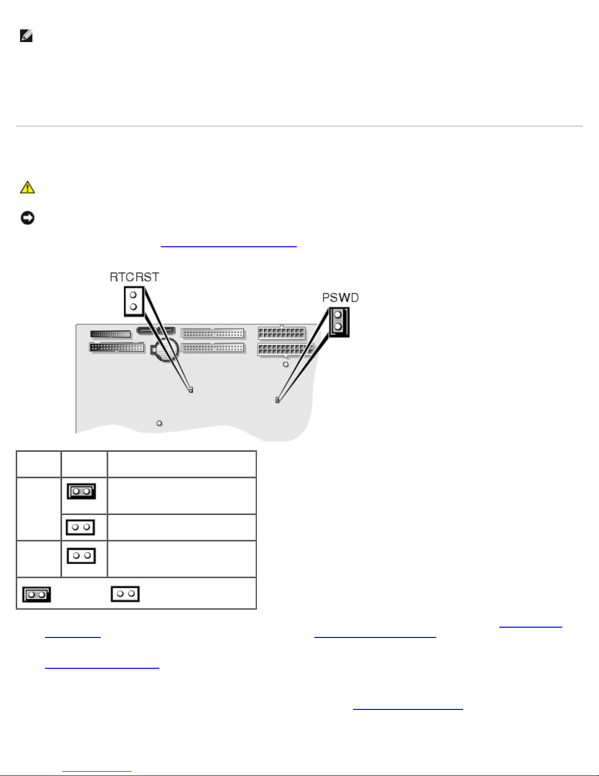
1. Follow the procedures in "Removing and Replacing Parts
Jumper Setting Description
PSWD
(default)
Password features are enabled.
Password features are disabled.
."
RTCRST
jumpered unjumpered
2. Locate the password jumper (PSWD) on the system board (for the Dell Precision 470 computer, see "System Board
Components" and for the Dell Precision 670 computer, see "System Board Components"), and remove the jumper plug
to clear the password.
3. Close the computer cover.
4. Connect your computer and monitor to electrical outlets, and turn them on.
5. After the Microsoft® Windows® desktop appears on your computer, shut down the computer
6. Turn off the monitor and disconnect it from the electrical outlet.
file:///T|/htdocs/systems/ws670/EN/ug_en/advfeat.htm[3/20/2013 9:31:46 AM]
Real-time clock reset.
.
Page 37

Advanced Features: Dell Precision Workstation 470 and 670 Computers User's Guide
7. Disconnect the computer power cable from the electrical outlet, and press the power button to ground the system
board.
8. Open the computer cover.
9. Locate the password jumper on the system board (for the Dell Precision 470 computer, see "System Board
Components" and for the Dell Precision 670 computer, see "System Board Components") and attach the jumper plug to
reenable the password feature.
10. Close the computer cover.
NOTICE: To connect a network cable, first plug the cable into the network wall jack and then plug it into the computer.
11. Connect your computer and devices to electrical outlets, and turn them on.
NOTE: This procedure enables the password feature. When you enter system setup, both system and admin password
options appear as Not Set—meaning that the password feature is enabled but no password is assigned.
12. Assign a new system and/or admin password.
Clearing CMOS Settings
CAUTION: Before you begin any of the procedures in this section, follow the safety instructions located in
the Product Information Guide.
1. Follow the procedures in "Removing and Replacing Parts
2. Reset the current CMOS settings:
a. Locate the password and CMOS jumpers (RTC_RST) on the system board (for the Dell Precision 470 computer,
see "System Board Components
b. Remove the jumper plug from its pins.
c. Place the password jumper plug on the RTC_RST pins and wait approximately 5 seconds.
d. Remove the jumper plug from the RTC_RST pins and place it back on the password pins.
e. Close the computer cover.
NOTICE: To connect a network cable, first plug the cable into the network wall jack and then plug it into the computer.
3. Connect your computer and devices to electrical outlets, and turn them on.
" and for the Dell Precision 670 computer, see "System Board Components").
."
Hyper-Threading
Hyper-Threading is an Intel® technology that can enhance overall computer performance by allowing one physical processor
to function as two logical processors, capable of performing certain tasks simultaneously. It is recommended that you use the
Microsoft® Windows® XP Service Pack 1 (SP1) operating system because Windows XP is optimized to take advantage of
Hyper-Threading technology. While many programs can benefit from Hyper-Threading, some programs have not been
optimized for Hyper-Threading and may require an update from the software manufacturer. Contact the software
manufacturer for updates and information about using Hyper-Threading with your software.
To determine if your computer is using Hyper-Threading technology:
file:///T|/htdocs/systems/ws670/EN/ug_en/advfeat.htm[3/20/2013 9:31:46 AM]
Page 38

Advanced Features: Dell Precision Workstation 470 and 670 Computers User's Guide
1. Click the Start button, right-click My Computer, and then click Properties.
2. Click Hardware and click Device Manager.
3. In the Device Manager window, click the plus (+) sign next to the processor type. If
Hyper-Threading is enabled, the processor is listed twice.
You can enable or disable Hyper-Threading through system setup. For more information, see "System Setup Options
."
IEEE 1394a
IEEE 1394a is a digital interface that can move large amounts of data between computers and peripheral devices. IEEE 1394a
is ideal for use with multimedia devices because it speeds the transfer of data and large files, which enables a computer to
connect directly to devices such as digital video cameras.
NOTE: The connector can accept six-pin IEEE 1394a devices with the use of an adapter.
Your computer provides a standard IEEE 1394a connector on both the front and back panels (see "Your Dell Precision™ 670
Computer" or "Your Dell Precision™ 470 Computer"). The front connector on the Dell Precision 470 computer is available with
an optional card.
U320 SCSI Controller
The U320 SCSI controller is PCI-X based and operates in a low voltage differential (LVD) mode while running at U320 (320
MBps) speeds. The bus is backward compatible and can run at U160 (160 MBps), Ultra2 (80 MBps), and Ultra (40 MBps)
speeds.
If single-ended (SE) devices are connected to the same bus as the LVD devices (such as U320, U160, or Ultra2), the SCSI
bus operates in SE mode and runs at a maximum of Ultra (40 MBps) speed.
For more information about installing a SCSI device and SCSI ID settings for your Dell Precision 670 computer, see "Drives
for the Dell Precision 670 Computer" and for your Dell Precision 470 computer, see "Drives for the Dell Precision 470
Computer."
NOTE: Due to resource constraints, you can not install more than one SCSI controller, regardless of make or model.
Power Management
Your computer can be set to use less power when you are not working. You control the power usage through the operating
system installed on your computer and certain option settings in system setup. These periods of reduced power are called
"sleep states:"
Standby — In this sleep state, power is reduced or turned off for most components, including the cooling fans.
However, system memory remains active.
NOTE: All components installed in the computer must support this feature and have the appropriate drivers loaded to
enter standby mode. For more information, see the manufacturer's documentation for each component.
Hibernate — This sleep state reduces power consumption to a minimum by writing all data in system memory to a
hard drive and then removing system power. Waking up from this state restarts the computer, and the memory
contents are restored. Operation then resumes where the computer left off when it entered the hibernation state.
NOTE: All components installed in the computer must support this feature and have the appropriate drivers loaded to
enter hibernation. For more information, see the manufacturer's documentation for each component.
Shutdown — This sleep state removes all power from the computer except a small auxiliary amount. As long as the
file:///T|/htdocs/systems/ws670/EN/ug_en/advfeat.htm[3/20/2013 9:31:46 AM]
Page 39
Advanced Features: Dell Precision Workstation 470 and 670 Computers User's Guide
computer remains connected to an electrical outlet, it can be automatically or remotely started. For example, the Auto
Power On option in system setup allows the computer to automatically start at a specified time. Also, your network
administrator can remotely start your computer using a power management event such as Remote Wake Up.
The following table lists the sleep states and the methods you can use to wake the computer from each state.
Sleep State Wake-Up Methods
Standby
Hibernate Press the power button
Shutdown Press the power button
NOTE: For more information on power management, see your operating system documentation.
Press the power button
Auto power on
Move or click the mouse
Type on the keyboard
USB device activity
Power management event
Auto power on
Power management event
Auto power on
Power management event
Copying CDs and DVDs
NOTE: Ensure that you observe all copyright laws when creating CDs or DVDs.
This section applies only to computers that have a CD-RW, DVD+/-RW, or CD-RW/DVD (combo) drive.
NOTE: The types of CD or DVD drives offered by Dell may vary by country.
The following instructions explain how to make an exact copy of a CD or DVD. You can also use Sonic DigitalMedia for other
purposes, such as creating music CDs from audio files stored on your computer or backing up important data. For help, open
Sonic DigitalMedia and then click the question mark icon in the upper-right corner of the window.
How to Copy a CD or DVD
NOTE: CD-RW/DVD combo drives cannot write to DVD media. If you have a CD-RW/DVD combo drive and you
experience recording problems, check for available software patches on the Sonic support website at www.sonic.com.
The DVD-writable drives installed in Dell™ computers can write to and read DVD+/-R, DVD+/-RW and DVD+R DL (dual layer)
media, but cannot write to and may not read DVD-RAM or DVD-R DL media.
NOTE: Most commercial DVDs have copyright protection and cannot be copied using Sonic DigitalMedia.
1. Click the Start button, point to All Programs® Sonic® DigitalMedia Projects, and then click Copy.
2. Under the Copy tab, click Disc Copy.
3. To copy the CD or DVD:
If you have one CD or DVD drive, ensure that the settings are correct and click the Disc Copy button. The
computer reads your source CD or DVD and copies the data to a temporary folder on your computer hard drive.
file:///T|/htdocs/systems/ws670/EN/ug_en/advfeat.htm[3/20/2013 9:31:46 AM]
Page 40
Advanced Features: Dell Precision Workstation 470 and 670 Computers User's Guide
When prompted, insert a blank CD or DVD into the drive and click OK.
If you have two CD or DVD drives, select the drive into which you have inserted your source CD or DVD and click
the Disc Copy button. The computer copies the data from the source CD or DVD to the blank CD or DVD.
Once you have finished copying the source CD or DVD, the CD or DVD that you have created automatically ejects.
Using Blank CDs and DVDs
CD-RW drives can write to CD recording media only (including high-speed CD-RW) while DVD-writable drives can write to
both CD and DVD recording media.
Use blank CD-Rs to record music or permanently store data files. After creating a CD-R, you cannot write to that CD-R again
(see the Sonic documentation for more information). Use blank CD-RWs to write to CDs or to erase, rewrite, or update data
on CDs.
Blank DVD+/-Rs can be used to permanently store large amounts of information. After you create a DVD+/-R disc, you may
not be able to write to that disc again if the disc is "finalized" or "closed" during the final stage of the disc creation process.
Use blank DVD+/-RWs if you plan to erase, rewrite, or update information on that disc later.
CD-Writable Drives
Media Type Read Write Rewritable
CD-R Yes Yes No
CD-RW Yes Yes Yes
DVD-Writable Drives
Media Type Read Write Rewritable
CD-R Yes Yes No
CD-RW Yes Yes Yes
DVD+R Yes Yes No
DVD-R Yes Yes No
DVD+RW Yes Yes Yes
DVD-RW Yes Yes Yes
DVD+R DL Yes Yes No
DVD-R DL Maybe No No
DVD-RAM Maybe No No
Helpful Tips
Use Microsoft® Windows® Explorer to drag and drop files to a CD-R or CD-RW only after you start Sonic DigitalMedia
and open a DigitalMedia project.
Use CD-Rs to burn music CDs that you want to play in regular stereos. CD-RWs do not play in most home or car
stereos.
You cannot create audio DVDs with Sonic DigitalMedia.
Music MP3 files can be played only on MP3 players or on computers that have MP3 software installed.
Commercially available DVD players used in home theater systems may not support all available DVD formats. For a list
file:///T|/htdocs/systems/ws670/EN/ug_en/advfeat.htm[3/20/2013 9:31:46 AM]
Page 41

Advanced Features: Dell Precision Workstation 470 and 670 Computers User's Guide
of formats supported by your DVD player, see the documentation provided with your DVD player or contact the
manufacturer.
Do not burn a blank CD-R or CD-RW to its maximum capacity; for example, do not copy a 650-MB file to a blank 650-
MB CD. The CD-RW drive needs 1–2 MB of the blank space to finalize the recording.
Use a blank CD-RW to practice CD recording until you are familiar with CD recording techniques. If you make a
mistake, you can erase the data on the CD-RW and try again. You can also use blank CD-RWs to test music file
projects before you record the project permanently to a blank CD-R.
See the Sonic website at www.sonic.com for additional information.
Back to Contents Page
file:///T|/htdocs/systems/ws670/EN/ug_en/advfeat.htm[3/20/2013 9:31:46 AM]
Page 42
RAID: Dell Precision Workstation 470 and 670 Computers User's Guide
2. Restart the computer.
Back to Contents Page
RAID
Dell Precision™ Workstation 470 and 670 Computers User's Guide
Features
Installing the Driver
Installing and Using RAID Storage Manager
Accessing RAID Storage Manager
Creating an Array
Choosing Between Express and Custom
Configuration
Deleting an Array
Manually Rebuilding a Failed Drive
Rebuilding to a Hot-Spare
Verifying an Array
SATA Host RAID
Features
Adaptec Embedded HostRAID supports:
RAID levels 0 and 1, using HostRAID technology
Using the Controller Configuration
Utility
Using the Disk Utilities
SCSI Host RAID
Creating Arrays
Deleting Arrays
Adding a Spare Drive
Rebuilding Arrays
Verifying Data Integrity
Bootable Array
Write Cache
Operating system-independent configuration and RAID creation for SCSI using SCSISelect
Operating system-independent configuration and RAID creation for Serial ATA using Adaptec RAID Configuration (ARC)
Easy array configuration and status using RAID Storage Manager
(Install the RAID Storage Manager as described in "Installing and Using RAID Storage Manager
Event logging
.")
Installing the Driver
When you install a driver in a new computer or update a driver in an existing computer, you need a driver disk. To obtain
drivers:
Visit the Dell Support website at support.dell.com and download the latest drivers for your controller. Follow the
instructions provided with the download.
Use the drivers provided with your Drivers and Utilities CD. See your User's Guide for more information about your
Drivers and Utilities CD.
Installing the Driver on a Computer Without an Operating System
1. Create a driver disk.
file:///T|/htdocs/systems/ws670/EN/ug_en/raid.htm[3/20/2013 9:31:47 AM]
Page 43

RAID: Dell Precision Workstation 470 and 670 Computers User's Guide
3. If you are creating an array, press <Ctrl><a> when you are prompted to enter the ARC utility. For instructions on
creating an array from the BIOS, see "Creating an Array
4. When the array is finished building, insert the Windows setup CD and restart the computer.
5. Press <F6> when you are prompted to install a third-party driver.
Press <F6> immediately—you only have 5 seconds. If you miss your chance, restart the Windows installation to
complete it correctly. Otherwise, Windows will not recognize your controller.
6. Insert the driver disk you created in step 1 and wait until you are prompted to install a driver.
7. Press <s> to specify that the driver is on the floppy disk, and press <Enter>.
Windows searches the disk for a suitable driver.
8. When the Embedded HostRAID driver is found, press <Enter>.
9. Follow the instructions on the screen to complete your installation.
."
Installing the Driver on a Computer With an Operating System Installed
1. Create a driver disk.
2. Restart the computer.
Windows launches the Found New Hardware Wizard, which searches for the controller driver.
3. Insert the driver disk you created in step 1, select the floppy drive as the source, and then click Next.
4. If necessary, select the appropriate driver for your operating system.
5. Click Next as needed to complete the controller installation.
6. Remove the driver disk.
7. If you are prompted to restart the computer, do so.
Your installation is complete. If you want to create an array from the BIOS, see "Creating an Array
create an array from the operating system, see "Installing and Using RAID Storage Manager
." If you want to
."
Installing and Using RAID Storage Manager
With the RAID Storage Manager, you can locally manage a computer containing a supported RAID controller that has the
Windows operating system installed. See the online help for information about creating, configuring, and managing arrays.
NOTE: Your controller may not support all of the features described. In most cases, if a feature is not supported by
your controller, the feature does not appear in the interface.
Installing the RAID Storage Manager on Windows
NOTE: When you are installing the RAID Storage Manager on a FAT 32 file system, the folder being installed is
automatically hidden.
1. Insert the Drivers and Utilities CD and wait for the Autorun executable to start the installation. If this does not happen,
browse the CD and click Autorun.
2. Click Install RAID Storage Manager.
3. Click Next in the Install Shield window.
file:///T|/htdocs/systems/ws670/EN/ug_en/raid.htm[3/20/2013 9:31:47 AM]
Page 44

RAID: Dell Precision Workstation 470 and 670 Computers User's Guide
4. Read the license agreement. If you agree to its terms, click Yes. If not, click No and terminate the installation.
5. Follow setup instructions to finish the installation.
6. When you are prompted to restart your computer, accept the default (Yes) and click Finish.
The computer restarts to complete the installation.
Using RAID Storage Manager
The action buttons are:
Logout — Selecting Logout ends your session and returns you to the Login screen.
Rescan — Used to rescan the configuration of the computer. Typically, when a rescan is required, it occurs
automatically; for example, after an array is created.
The remaining buttons open additional windows that provide more detailed information, and allow you to perform actions or
change settings of a specific aspect of your storage subsystem.
Events
Options
Help
Properties
Immediately following the header frame is a controller information line including the model number of the first RAID controller
found in the computer.
Beneath the controller information are Physical Devices and Logical Devices views that show connected devices and
existing arrays on this controller. Controller information and device views are repeated for each additional RAID controller in
the computer.
Select the controller by clicking anywhere on the controller information. When you select the controller, the Events,
Properties, and Tasks buttons change from blue to amber, indicating that clicking any of them displays an additional
window with information and options specific to this controller.
Pop-Up Tool Tips
If you position the cursor over a device or button, a pop-up tool tip appears. For buttons, the tips contain helpful information
about the function of the button, while for devices the tips display additional information.
Physical Devices
The Physical Devices view displays information about the drives attached to the RAID controller. The devices shown are
organized by the channel or port to which they are connected and they are listed in numerical order.
The display for each channel includes information on maximum speed capability, the number of the channel on the controller,
and the number of devices found (excluding the SCSI controller).
Selecting a channel or device turns the Events, Properties, and Tasks buttons amber. The amber color indicates that
clicking any of these buttons displays an additional window with information and options specific to that device or channel.
At the top of the Physical Devices view, grouped to the right of View, are three view selection buttons. These buttons select
the physical devices connected to the controller.
Changing How Drives are Displayed
file:///T|/htdocs/systems/ws670/EN/ug_en/raid.htm[3/20/2013 9:31:47 AM]
Page 45

RAID: Dell Precision Workstation 470 and 670 Computers User's Guide
By default, the Physical Devices view displays a condensed snapshot of the controller configuration that hides detailed
information about the drives. More information is available by either positioning the mouse pointer over the device or clicking
the arrow to the left of a row of devices.
The selected display mode button appears in a lighter shade of blue than the other two buttons. The default display is the
Text Description View, but in the condensed view that is used when the RAID Storage Manager is loaded, the display is the
same in all three modes.
If you change the display mode by selecting one of the other view buttons, a yellow arrow flashes to the left of any devices
where the condensed display hides information.
An icon is always the first entry on each device line. If a + symbol appears with the hard drive icon, the drive is a hot spare.
Different icons are used to represent other devices.
View
When you expand the default display mode, the following information about each device appears:
Capacity of the drive
Drive manufacturer and model number
SCSI drive ID or Serial ATA port number
When you expand them, the Full Size Capacity View button and the Relative Size Capacity View button represent each
drive as a bar. A drive that is not used as part of any array is blue and is surrounded by a dotted line.
The Full Size Capacity View button displays a full-length bar for each drive, regardless of capacity. The Relative Size
Capacity View button displays a bar for each drive, with the largest capacity drive full-length and the other drives
proportional to the drive capacity, relative to the largest drive.
Any part of a drive used in an array is shown as a gray segment within the bar. Selecting any gray segment highlights it in
amber, and in the Logical Devices view.
In either the Full Size Capacity View or the Relative Size Capacity View, a small portion at each end of the drive may be
shown in dark gray.
The segment at the end of the drive may vary in size from drive to drive because, in addition to the RAID signature, the
controller may also limit the usable capacity of each drive.
This is done because hard drives that appear to have the same capacity and that are made by different manufacturers, or
even different models from the same manufacturer, actually vary slightly in the true capacity available. In normal operation,
this is not an issue, it can be when assigning hot spares or replacing a failed drive.
If the controller uses the maximum capacity of each drive and a hot spare or replacement drive is just a few megabytes
smaller, it is not possible to replace the failed drive. By rounding drive capacities down to the nearest 2 MB, this possibility is
effectively eliminated.
Logical Devices
As described earlier, when the RAID Storage Manager loads, the Logical Devices view is expanded and you can see the
arrays present on the controller.
At the top of this view are the following buttons: Create, Modify, and Delete. Each button opens a wizard for the
corresponding function.
Modify allows you to:
Change an array from one RAID level to another.
Change the stripe size for a RAID 0.
The main area of the Logical Devices view is used to display the arrays on this controller. It defaults to a condensed view of
top-level arrays.
file:///T|/htdocs/systems/ws670/EN/ug_en/raid.htm[3/20/2013 9:31:47 AM]
Page 46

RAID: Dell Precision Workstation 470 and 670 Computers User's Guide
NOTE: The Options button allows you to display second-level arrays if your controller supports them.
In this condensed view, the RAID level of each device, as well as whether it is protected by a hot spare, is visible. If a global
hot spare exists, all arrays that the hot spare is large enough to protect shows as protected.
In the expanded view, the icons for the arrays are arranged vertically and next to them are the capacity, name, and type of
arrays.
Selecting an array by clicking on it highlights the following in amber:
All the drives or segments that form the array in the Physical Devices view.
The Events, Properties, and Tasks buttons in the header frame. Selecting any of these three buttons displays a new
window with additional information and options specific to that array.
Accessing RAID Storage Manager
Starting the RAID Storage Manager in the Windows Operating System
1. Open the program by clicking the Start button, pointing to Programs® RAID Storage Manager, and clicking RAID
Storage Manager.
2. The program flash screen appears briefly, then a login dialog box opens. Enter the user name and password you use to
log on to your operating system, and click Connect.
NOTE: Your RAID Storage Manager permissions vary according to your operating system permissions:
Administrator: The Administrator log in allows you to view and modify the RAID configuration. You can create and
delete logical devices, add and remove hot-spare drives, and verify logical devices. To log in as Administrator, you
must be a member of the Administrator group for your operating system. Use the Administrator user name and
password or your own user name and password if you are a member of the Administrator group.
User: The User log in allows you to view the RAID configuration, verify logical devices, and add and remove hotspares. You cannot create or delete logical devices. To log in as User, use your normal network user name and
password.
Guest: The Guest log in allows you to view the RAID configuration only. You cannot change or modify any information.
To log in as Guest, click Cancel when the RAID Storage Manager Log in window opens.
Creating an Array
To create an array:
1. In the Controller view, click the controller that you want to configure.
2. Right-click Create logical drive.
The Configuration wizard opens.
3. Click either Express configuration or Custom configuration. See "Choosing Between Express and Custom
Configuration" for more information.
If you select Express configuration, the RAID Storage Manager automatically:
Creates one or more logical devices, based on the number and size of ready physical drives in your computer.
Defines a hot-spare drive, if four or more ready physical drives of the same size are available.
file:///T|/htdocs/systems/ws670/EN/ug_en/raid.htm[3/20/2013 9:31:47 AM]
Page 47

RAID: Dell Precision Workstation 470 and 670 Computers User's Guide
NOTE: For HostRAID controllers, Express configuration creates a single RAID Level-1 logical device; it does not create
a hot spare drive.
If you select Custom configuration, the RAID Storage Manager guides you through:
Defining the RAID level of the logical devices.
Selecting the physical drives that you want to include for each logical device.
Defining the number and size of the logical devices.
Fine-tuning your configuration for optimal performance.
4. Click Next and review the configuration summary.
5. Click Apply.
The RAID Storage Manager configures the controller and initializes the logical devices.
Choosing Between Express and Custom Configuration
In the Configuration wizard, you can choose from two methods to configure your controller:
Express Configuration
Click the Express configuration for a quick and easy method to automatically configure your controller. This path creates the
most efficient configuration based on the number and capacity of the ready physical drives available in your computer. If four
or more ready drives of the same capacity are available, this choice also defines a hot-spare drive for the controller. If four or
more ready drives are available, the largest drive is designated as the hot-spare drive.
NOTE: For HostRAID controllers, Express configuration creates a RAID level-1 logical drive.
NOTE: When you choose Express configuration, you have the opportunity to review and approve the configuration
before the RAID Storage Manager applies the configuration. If you need to modify the configuration, you can do so
from the configuration summary.
Custom Configuration
Click the Custom configuration for a method that lets you manually configure your controller.
Choose this method to do any of the following:
Define the RAID level of the logical drives.
Select the physical drives that you want to include for each logical drive.
Define the number and size of the logical drives.
Fine tune your configuration for optimal performance
Review the configuration summary.
Deleting an Array
NOTICE: Deleting an array destroys all data on the array. Deleting the array on which the operating system resides
destroys the operating system and all data, and the computer no longer boots. Only delete data arrays, or backup data
file:///T|/htdocs/systems/ws670/EN/ug_en/raid.htm[3/20/2013 9:31:47 AM]
Page 48

RAID: Dell Precision Workstation 470 and 670 Computers User's Guide
before deleting the boot array. For some operating systems, deleting a disk group and its associated logical drives
might change the drive-letter assignments of the remaining drives when you restart the computer.
NOTICE: If you delete a disk group, you delete all logical devices that are defined in that disk group. All data and
programs on the logical devices in the disk group are lost during this procedure.
To delete a disk group:
1. In the Physical devices view, click the array.
NOTICE: Before proceeding, ensure that you have backed up any data and programs that you want to save.
2. Right-click Delete disk group.
3. Click Yes.
Manually Rebuilding a Failed Drive
Use this action to rebuild a degraded logical device when a physical drive in the disk group is failed. Normally, the controller
rebuilds a logical device when it detects the removal and reinsertion of a drive that is part of a disk group. Use this operation
to force the rebuild to begin immediately, without physically removing and replacing the disk drive.
NOTE: The controllers can rebuild RAID level-1 logical devices. They cannot, however, rebuild RAID level-0 logical
devices because RAID level-0 is not redundant.
To manually rebuild a failed drive:
1. In the Physical devices view, click the failed physical drive.
2. Right-click Rebuild drive.
3. Click Yes.
NOTE: During the rebuild operation, the failed drive enters the rebuild state and the logical device remains degraded
until the rebuild operation is completed.
Rebuilding to a Hot-Spare
When a hot-spare drive is available, the rebuild operation begins automatically without the need to replace the failed drive. If
more than one drive fails within the same disk group, no rebuild takes place. If multiple drives fail in separate disk groups
(one physical drive per array), the controller initiates a rebuild operation for the logical devices within the disk group
containing the first failed physical drive. The rebuild operation is performed on the first hot-spare drive of sufficient size to
become a valid member of the disk group.
Verifying an Array
Use this action to check redundant logical drives for inconsistent or bad data. Verification is similar to Verify with Fix, except
that the RAID Storage Manager does not repair the drive if bad data is found. Verification can be a lengthy operation. You
cannot perform any other actions on the controller until the verification is completed. You can verify the logical drive
immediately or schedule it for another time. You can also schedule the verification as a recurring task. A recurring task starts
at the initial start time, then runs periodically according to the given interval: the same time each day, the same time each
week, or the same time each month.
NOTE: You cannot perform any other actions on the controller until the verification is completed. For example, you
cannot schedule a verification if another logical drive verification is in progress.
file:///T|/htdocs/systems/ws670/EN/ug_en/raid.htm[3/20/2013 9:31:47 AM]
Page 49

RAID: Dell Precision Workstation 470 and 670 Computers User's Guide
NOTE: Do not turn off the computer while verification is in progress.
To verify a logical drive:
1. In the Logical devices view, click the logical drive you want to verify.
2. Right-click Verify or Verify with Fix.
3. To verify the logical drive now, click Yes. To schedule the verification for a later date and time, click Schedule.
The RAID Storage Manager displays the Scheduler pane:
From the drop-down lists and calendar display, select the day, month, year, and time you want the task
performed.
From the Recurring drop-down list, select the interval at which you want the task to recur: Never, Daily,
Weekly, or Monthly.
Click OK to schedule the task; click Cancel to cancel the scheduled task and return to the initial confirmation
pane.
SATA Host RAID
With the Adaptec RAID Configuration Utility (ACU), you can create and manage RAID arrays with drives connected to a SATA
controller. This section explains how to use ACU and two host RAID levels to provide the proper level of fault tolerance and
event notification. See "SCSI Host RAID
HostRAID supports the following RAID levels:
RAID 0 — Striping mode for boosting performance
RAID 1 — Mirroring mode for data security
."
Creating Arrays
Before creating arrays, make sure the disks for the array are connected and installed in your computer. Note that disks with
no usable space, or disks that are part of the RAID array are shown in gray and cannot be used. See "Configuring Drives."
To create an array:
1. Turn on your computer and press <Ctrl><a> when you are prompted to access the ARC utility.
2. From the ARC menu, select Array Configuration Utility (ACU) and press <Enter>.
3. From the ACU menu, select Create Array by using the up- and down-arrow keys.
4. Select the disks for the new array and click Insert. To deselect any disk, highlight the disk and click Delete.
5. Press <Enter> when disks for the new array are selected.
The Array Properties menu displays.
Assigning Array Properties
NOTE: Once the array is created and its properties are assigned, you cannot change the array properties using the
ACU.
Tips for assigning an array:
Before adding a new drive to an array, back up any data contained on the new drive. Otherwise, all data will be lost.
file:///T|/htdocs/systems/ws670/EN/ug_en/raid.htm[3/20/2013 9:31:47 AM]
Page 50
RAID: Dell Precision Workstation 470 and 670 Computers User's Guide
If you stop the Build or Clear process on a RAID 1 from ACU, you can restart it by simultaneously pressing <Ctrl><r>.
If you created a RAID 1 using the Quick Init option, you may notice that data comparisons do not match when you
run a consistency check.
The ACU allows you to use drives of different sizes in a RAID 1. However, during a build operation, only the smaller
drive can be selected as the source or first drive.
It is recommended that you do not migrate or build an array on Windows dynamic disks (volumes), as it will result in
data loss.
NOTICE: Do not interrupt the creation of a RAID 0 using the Migrate option. If you do, there is no way to restart, and
no way to recover the data that was on the source drive.
To assign properties to the new array:
1. In the Array Properties menu, select an array type and press <Enter>. Note that only the available array types, RAID
0 and RAID 1, are displayed. RAID 0 and RAID 1 require a minimum of two drives.
2. Type in an optional label of no more than 15 characters for the array, and press <Enter>.
3. For RAID 0, select the desired stripe size. Available stripe sizes are 16, 32, and 64 KB (default).
NOTE: It is recommended that you do not change the default.
You can select between the different creation methods for RAID 0 and RAID 1. The following table gives examples of
when each is appropriate.
RAID
Level
RAID 0 No Init Creating a RAID 0 on new drives.
RAID 0 Migrate* Creating a RAID 0 on a new drive and one drive with data you want to preserve.
RAID 1 Build* Any time you wish to create a RAID 1, but especially if you have data on one drive that you want to
RAID 1 Clear Creating a RAID 1 on new drives, or when you want to ensure that the array contains no data after
RAID 1 Quick Init Fastest way to create a RAID 1 (is appropriate when using new drives).
*If you select Migrate for RAID 0 or Build for RAID 1, you are asked to select the source drive. The contents of the source
drive are preserved; however, the data on the new drive is lost.
4. When you are finished, select Done.
Create
Via
When Appropriate
preserve.
creation.
Configuring Drives
If an installed disk does not appear in the disk selection list for creating a new array, or if it appears grayed out, you may
have to initialize it before you can use it as part of an array. Drives attached to the controller must be configured before they
can be used in an array.
1. Turn on your computer and press <Ctrl><a> when you are prompted to access the ARC utility.
2. From the ARC menu, select Array Configuration Utility (ACU).
3. Select Configure Drives.
4. Use the up- and down-arrow keys to highlight the disk you want to configure and select Insert.
file:///T|/htdocs/systems/ws670/EN/ug_en/raid.htm[3/20/2013 9:31:47 AM]
Page 51

RAID: Dell Precision Workstation 470 and 670 Computers User's Guide
5. Repeat step 4 so that all drives to be initialized are selected.
6. Press <Enter>.
7. Read the warning message and ensure that you have selected the correct disk drives to initialize. Press <y> to
continue.
Rebuilding Arrays
NOTE: Rebuilding applies to Fault Tolerant arrays (RAID 1) only.
If an array Build process (or initialization) is interrupted or critical with one member missing, you must perform a Rebuild to
get the array to Optimal status. For a critical array Rebuild operation, the optimal drive is the source drive.
NOTE: If no spare exists and a hard disk drive fails, you need to create a spare before you can rebuild an array. See
"Add/Delete Hotspares
1. From the Main Menu, select Manage Arrays.
2. From the List of Arrays, select the array you want to rebuild.
" before continuing your Rebuild.
3. Press <Ctrl><r> to rebuild.
Verifying Drives
If you are notified of a mismatch of data during a build of RAID 1, you have an option of synchronizing your drives.
NOTE: You only have the synchronize option available if the array is Optimal. If the array has failed, you need to
rebuild the array.
1. Select the drives you need to synchronize.
2. Press <Ctrl><s>.
3. Select Yes when the following prompt is displayed:
Do you want utility to automatically fix errors? (Yes/No)
When the synchronization is complete, you are notified with a fix message.
Deleting Arrays
NOTICE: Back up the data on an array before you delete it. Otherwise, all data on the array is lost. Deleted arrays
cannot be restored.
To delete an existing array:
1. Turn on your computer and press <Ctrl><a> when you are prompted to access the ARC utility.
2. From the ARC menu, select Array Configuration Utility (ACU) and press <Enter>.
3. From the ACU menu, select Manage Arrays using the up- and down-arrow keys.
4. Select the array you want to delete and press <Delete>.
5. In the Array Properties dialog box, select Delete and press <Enter>.
The following prompt is displayed:
file:///T|/htdocs/systems/ws670/EN/ug_en/raid.htm[3/20/2013 9:31:47 AM]
Page 52

RAID: Dell Precision Workstation 470 and 670 Computers User's Guide
Warning!! Deleting the array will render array unusable. Do you
want to delete the array?(Yes/No):
6. Select Yes to delete the array or partition or No to return to the previous menu.
RAID 1 only—the following prompt is also displayed:
Deleting the partition will result in data loss! Do you also want
to delete the partition? Choose which member:
[NONE] [MEMBER #0] [MEMBER #1] [BOTH]
7. Select [BOTH] and press <Enter>.
8. Press <Esc> to return to the previous menu.
Add/Delete Hotspares
Select the Add/Delete Hotspares option to add, delete, or view hotspares.
1. Turn on your computer and press <Ctrl><a> when you are prompted to access the ARC utility.
2. From the ARC menu, select Array Configuration Utility (ACU).
3. From the ACU menu, select Add/Delete Hotspares by using the up- and down-arrow keys.
4. Use the up- and down-arrow keys to highlight the disk you want to designate as a Hotspare, select Insert, and then
press <Enter>.
5. Select Yes when the following prompt is displayed:
Do you want to create spare? (Yes/No)
The Spare you have selected appears in the Assigned Hot Spare Drive menu.
Viewing Array Properties
To view the properties of an existing array:
1. At the BIOS prompt, press <Ctrl><a>.
2. From the ARC menu, select Array Configuration Utility (ACU).
3. From the ACU menu, select Manage Arrays.
4. From the List of Arrays dialog box, select the array you want to view and press <Enter>.
The Array Properties dialog box appears, showing detailed information on the array. The physical disks associated
with the array are displayed here.
5. Press <Esc> to return to the previous menu.
Using the Controller Configuration Utility
1. Turn on your computer and press <Ctrl><a> when you are prompted to access the ARC utility.
2. If multiple controllers are installed, select the controller you want to configure and press <Enter>.
file:///T|/htdocs/systems/ws670/EN/ug_en/raid.htm[3/20/2013 9:31:47 AM]
Page 53

RAID: Dell Precision Workstation 470 and 670 Computers User's Guide
3. From the ARC menu, select SATASelect.
The Controller Configuration and SATA Configuration menu options are displayed.
4. Select Controller Configuration.
You can modify the following Controller Interface options:
Runtime BIOS (Default: Enabled) — Enables or disables the controller's runtime BIOS. The BIOS must be
enabled if you want to boot from the controller.
If Runtime BIOS is enabled and the Array-based BBS Support option is disabled, the controller BIOS is
enabled and post to the first array (or drive) attached to the controller as a bootable hard disk drive.
Using the Disk Utilities
The Disk Utilities enable you to format or verify the media of your Serial ATA hard disks.
1. Turn on your computer and press <Ctrl><a> when you are prompted to access the ARC utility.
2. From the ARC menu, select Disk Utilities.
3. Select the desired disk and press <Enter>.
The following options appear:
Format Disk — Simulates a low-level format of the hard drive by writing zeros to the entire disk. Serial ATA
drives are low-level formatted at the factory and do not need to be low-level formatted again.
NOTICE: Formatting destroys all data on the drive. Be sure to back up your data before performing this operation.
Verify Disk Media — Scans the media of a disk drive for defects.
SCSI Host RAID
With the SCSISelect utility, you can create and maintain RAID arrays with drives connected to a SCSI controller.
NOTE: Only the Dell Precision® 670 computer has RAID arrays with drives connected to a SCSI controller on the
system board. You cannot use the SCSISelect utility with the Dell Precision 470 computer.
This section explains how to use the SCSISelect utility to create and manage RAID arrays on your computer. Use HostRAID to
provide the proper level of fault tolerance and event notification.
HostRAID supports the following RAID levels:
RAID 0 — Striping mode for boosting performance
RAID 1 — Mirroring mode for data security
Using SCSISelect Utility Menus
To select a SCSISelect menu option, move the cursor to the option with the arrow keys and then press <Enter>. In some
cases, selecting an option displays another menu. You can return to the previous menu at any time by pressing <Esc>.
file:///T|/htdocs/systems/ws670/EN/ug_en/raid.htm[3/20/2013 9:31:47 AM]
Page 54

RAID: Dell Precision Workstation 470 and 670 Computers User's Guide
Starting the SCSISelect Utility
1. Turn on or restart your computer.
During the startup process, pay careful attention to the messages that appear on your screen.
2. When the following message appears on your screen, press <Ctrl><a> (this message appears for only a few seconds):
Press <Ctrl><A> for SCSI Select (TM) Utility!
3. From the device menu that appears, select a channel and press <Enter>.
4. From the Options menu, select Configure/View HostRAID Settings and press <Enter>.
After scanning the device is completed, the Main menu appears. The Main menu displays the following information:
ID — Indicates ID number of hard drive.
Type — Indicates available non-array hard drive, RAID type, or global spare:
Striped (R0)
Mirrored (R1)
Hard Drive
Spare
Vendor — Indicates vendor of hard drive.
Product — Indicates model of hard drive or name of built array.
Size — Indicates size of hard drive.
Status — Indicates available RAID status:
Free — Available drive
Optimal — No defect
Degraded — One drive in a mirrored array is in failed status, and a Rebuild option is available.
Dead — One drive in a RAID 0 array is in failed state or missing.
Building — The drive is a target of an ongoing Rebuild operation.
Verifying — Checking the data integrity of redundant data stored on fault-tolerant arrays.
Viewing Array
To view an array, select the array and press <Enter>. A detailed view of the hard drives appears. From this window you can
see the status of the individual hard drives. The status levels you might see are:
Optimal — No defect.
Building — The drive is a target of an ongoing Rebuild operation.
Verify — Checking the data integrity of redundant data stored on fault-tolerant arrays.
Missing drive information indicates that a member is missing and the array is not optimal
file:///T|/htdocs/systems/ws670/EN/ug_en/raid.htm[3/20/2013 9:31:47 AM]
Page 55

RAID: Dell Precision Workstation 470 and 670 Computers User's Guide
Exiting the SCSISelect Utility
1. Press <Esc> until a message prompts you to exit (if you changed any settings, you are prompted to save the changes
before you exit).
2. At the prompt, select Yes to exit. If prompted, press any key to restart the computer. Any changes you made in
SCSISelect take effect after the computer restarts.
Creating Arrays
Before creating the array, make sure that the disks for the array are connected and installed in your computer, and then
follow these steps:
1. Turn on the computer and press <Ctrl><a> when you are prompted to access SCSISelect.
2. Select Configure/View HostRAID Settings.
3. From the Main menu, select C to create a RAID array.
NOTE: You must have at least two hard drives to create an array.
NOTE: If the hard drive you select is already part of an array configuration, it will not be available for selection.
4. Select the RAID type you want to build. As you highlight the selections, you receive an allowance message regarding
minimum and maximum drives. Press <Enter>.
The allowance messages for the different RAID types are as follows:
RAID-0
Min 2 drives
RAID-1
Min 2 drives, max 2 drives
5. From the Select RAID Member menu, press the spacebar to select the hard drives you want to use in the array. An X
appears next to the drives you have selected.
Creating RAID 0 Arrays
1. From the Select RAID Type window, select RAID-0 and press <Enter>.
2. Select the hard drives you want to use and press <Enter>.
3. Select Yes to quick build this array, and then press <Enter>.
4. Select Enable Write Cache if you want to enable cache on the drive and press <Enter>.
5. Select the stripe size and press <Enter>. You can select from 16K, 32K, or 64K (default). If a partition exists on any of
the selected drives, you receive a message that the partition will be deleted.
6. Assign a RAID name by entering up to 15 alphabetic or numeric characters, and then press <Enter>.
The following message appears:
file:///T|/htdocs/systems/ws670/EN/ug_en/raid.htm[3/20/2013 9:31:47 AM]
Page 56

RAID: Dell Precision Workstation 470 and 670 Computers User's Guide
Do you want to make this array bootable?
7. Select Yes if you want to make the array bootable.
The following message appears: Create Array?
8. Select Yes.
The following message appears: Are you sure?
9. Select Yes and press <Enter> to create a RAID 0 array.
After your array is created, you automatically return to the Main menu.
Creating RAID 1 Arrays
There are two ways to create a RAID 1 array. You can create a new RAID 1 array or you can migrate from an existing single
drive to a RAID 1 array. To create a RAID 1 array using either option:
1. From the Select RAID Type window, select RAID-1.
2. Select the hard drives you want using the spacebar to toggle, and then press <Enter>.
3. Select Yes to quick build this array, and then press <Enter>.
4. Select Disable Write Cache from the write cache options window and press <Enter>.
5. The RAID-1 Build Option window appears if you selected No for the quick build option. Select an option and press
<Enter>.
Create new RAID-1 — The default option.
Copy from (ID#) to (ID#) — Copy from a source drive to a target drive if the source is equal to or smaller than
the target.
Copy from (ID#) to (ID#) — Copy from a source drive to a target drive if the source is equal to or smaller than
the target.
NOTE: If a valid partition table or boot block is detected in the target drive, you receive a warning that that the
information will be destroyed.
6. After entering your options, if a partition exists on any of the selected drives, you get a message that the partition will
be deleted. Assign a RAID name by entering up to 15 alphabetic or numeric characters, and then press <Enter>.
The following message appears: Do you want to make this array bootable?
7. Select Yes if you want to make the array bootable.
The following message appears: Create Array?
8. Select Yes.
The following message appears: Are you sure?
9. Select Yes and press <Enter> to create a RAID 1 array.
If you select No, the RAID creation terminates and you return to the Main menu.
After your array is created, the progress bar appears showing the percentage completed in the creation process. If for
any reason you want to stop the build process and return to the Main menu, press <Esc>. You may continue the build
process by selecting the Rebuild function later.
NOTE: You might not be able to use the array if the build has not been entirely completed.
To add a spare to an existing RAID 1 array, see "Adding a Spare Drive
Creating a Configured Single Disk
file:///T|/htdocs/systems/ws670/EN/ug_en/raid.htm[3/20/2013 9:31:47 AM]
."
Page 57

RAID: Dell Precision Workstation 470 and 670 Computers User's Guide
1. From the Select RAID Type window, select Configured Single and press <Enter>.
2. Select the hard drives you want to use and press <Enter>.
NOTE: If a valid partition table or boot block is detected in the target drive, you get a warning message that the
dynamic partition disk(s) will be converted to the basic partition disk(s).
Deleting Arrays
1. From the Main menu, select the array you need to delete by moving the cursor, and then press <Enter>.
2. Select D.
The following message appears: Delete Array?
3. For RAID 0, go to step 4. For RAID 1, select one of these options, then continue to step 4:
Drive ID 1 — Deletes all data on the drive 1
Drive ID 2 — Deletes all data on the drive 2
Drive ID 1 & 2 — Deletes all data on both drives
None — Breaks the array but keeps any existing data on both drives
4. Select Yes and press <Enter>.
The following message appears: Are you sure?
5. Select Yes and press <Enter>.
If you select No, you return to the Main menu.
Adding a Spare Drive
With RAID 1 you have the option to create a maximum of 2 spare drives. You can create a spare before you define your RAID
or you can add a spare later to an existing RAID 1 array.
1. From the Main menu, select S to add a spare.
The following options appear:
Add Spare
Delete Spare (only available if a spare already exists)
2. Select a drive and press <Enter>.
3. Select Yes when the following message appears:
Are you Sure?
Yes/No
After you select your spare drive, it appears as a spare in the Main menu.
Rebuilding Arrays
NOTE: Rebuilding applies to Fault Tolerant arrays (RAID 1) only.
If an array Build process (or initialization) is interrupted or critical with one member missing, you must perform a Rebuild to
get the array to Optimal status. For a critical array Rebuild operation, the optimal drive is the source drive.
file:///T|/htdocs/systems/ws670/EN/ug_en/raid.htm[3/20/2013 9:31:47 AM]
Page 58

RAID: Dell Precision Workstation 470 and 670 Computers User's Guide
NOTE: If no spare exists and a hard disk drive fails, you need to create a spare before you can rebuild an array. See
"Adding a Spare Drive" before continuing your Rebuild.
To rebuild an array for RAID 1:
1. From the Main menu, select an array for Rebuild and press <Enter>.
2. Select R for Rebuild.
If your array rebuilds successfully, the following message appears: Build/Rebuild Completed.
3. Press any key to return to the Main menu.
NOTE: During the Rebuild process, you can stop the Rebuild by pressing <Esc>. You get a pop-up window displaying
Stop Build? If you select Yes, you return to the Main menu.
Verifying Data Integrity
NOTE: To verify data integrity, your RAID 1 must be at Optimal status.
1. From the Main menu, select array, press <Enter>, and then select V.
2. Select Yes and press <Enter>.
If you select No, you return to the Main menu.
NOTE: During the Verify process, you can stop the Verify by pressing <Esc>. You get a pop-up window displaying
Stop Verify? If you select Yes, you return to the Main menu.
3. If a message asking if you want to automatically fix errors appears, select Yes to AutoFix. This executes a comparison
of mirrored drives, a copy from the primary drive to secondary drive when a miscompare occurs, and a report at the
end of the verification process.
If you select No, this executes a comparison of mirrored drives, a log of errors, and a report at the end of the
verification process.
NOTE: To fix errors found (if any), run Verify again with Autofix=Yes.
After you select your verification option, the following message appears: Depending on your disk capacity, verifying
may take several minutes to several hours. Are you sure?
4. When your Verify is completed, you get a verification message and log. Press <Esc> to exit.
If your Verify is unsuccessful, you get the following message: WARNING: Failed !!!
5. Press <Enter> and return to the Main menu.
Bootable Array
1. From the Main menu, select an array, press <Enter>, and then select B for the Bootable function.
2. Select Mark Bootable and press <Enter>.
NOTE: Mark Bootable gives boot priority to the array regardless of the SCSI ID priority.
file:///T|/htdocs/systems/ws670/EN/ug_en/raid.htm[3/20/2013 9:31:47 AM]
Page 59

RAID: Dell Precision Workstation 470 and 670 Computers User's Guide
Write Cache
1. From the Main menu, select Array, press <Enter>, and then select W for the write cache setting change.
2. Select Write Cache Setting from the write cache options window and press <Enter>.
3. For the non-RAID array drives, select W from the Main menu.
4. Choose the drive and press <Enter>.
Back to Contents Page
file:///T|/htdocs/systems/ws670/EN/ug_en/raid.htm[3/20/2013 9:31:47 AM]
Page 60
Removing and Replacing Parts: Dell Precision Workstation 470 and 670 Computers User's Guide
Back to Contents Page
Removing and Replacing Parts
Dell Precision™ Workstation 470 and 670 Computers User's Guide
Before You Begin
Opening the Computer Cover
Memory
Drives for the Dell Precision 670 Computer
Drive Door for the Dell Precision 670
Computer
Drives for the Dell Precision 470 Computer
Cards
Processor Airflow Shroud
Processor
Battery
VRM
Control Panel
Front Panel
I/O Panel
Power Supply for the Dell Precision 670
Computer
Power Supply for the Dell Precision 470
Computer
System Board
Closing the Computer Cover
Before You Begin
This chapter provides procedures for removing and installing the components in your computer. Unless otherwise noted, each
procedure assumes that the following conditions exist:
You have performed the steps in "Turning Off Your Computer" and "Before Working Inside Your Computer."
You have read the safety information in your Dell™ Product Information Guide.
A component can be replaced by performing the removal procedure in reverse order.
Recommended Tools
The procedures in this document may require the following tools:
Small flat-blade screwdriver
Phillips screwdriver
Flash BIOS update program floppy disk or CD
Turning Off Your Computer
NOTICE: To avoid losing data, save and close any open files and exit any open programs before you turn off your
computer.
1. Shut down the operating system:
a. Save and close any open files, exit any open programs, click the Start button, and then click Turn Off
Computer.
b. In the Turn off computer window, click Turn off.
file:///T|/htdocs/systems/ws670/EN/ug_en/before.htm[3/20/2013 9:31:52 AM]
Page 61

Removing and Replacing Parts: Dell Precision Workstation 470 and 670 Computers User's Guide
The computer turns off after the operating system shutdown process finishes.
2. Lay the computer on its side as shown in the illustration.
2. Ensure that the computer and any attached devices are turned off. If your computer and attached devices did not
automatically turn off when you shut down your operating system, turn them off now.
Before Working Inside Your Computer
Use the following safety guidelines to help protect your computer from potential damage and to help ensure your own
personal safety.
CAUTION: Before you begin any of the procedures in this section, follow the safety instructions located in
the Product Information Guide.
CAUTION: Handle components and cards with care. Do not touch the components or contacts on a card.
Hold a card by its edges or by its metal mounting bracket. Hold a component such as a processor by its
edges, not by its pins.
NOTICE: Only a certified service technician should perform repairs on your computer. Damage due to servicing that is
not authorized by Dell is not covered by your warranty.
NOTICE: When you disconnect a cable, pull on its connector or on its strain-relief loop, not on the cable itself. Some
cables have a connector with locking tabs; if you are disconnecting this type of cable, press in on the locking tabs
before you disconnect the cable. As you pull connectors apart, keep them evenly aligned to avoid bending any
connector pins. Also, before you connect a cable, ensure that both connectors are correctly oriented and aligned.
NOTICE: To avoid damaging the computer, perform the following steps before you begin working inside the computer.
1. Turn off your computer
NOTICE: To disconnect a network cable, first unplug the cable from your computer and then unplug it from the
network wall jack.
2. Disconnect any telephone or telecommunication lines from the computer.
3. Disconnect your computer and all attached devices from their electrical outlets, and then press the power button to
ground the system board.
CAUTION: To guard against electrical shock, always unplug your computer from the electrical outlet before
opening the cover.
4. Open the computer cover
NOTICE: Before touching anything inside your computer, ground yourself by touching an unpainted metal surface,
such as the metal at the back of the computer. While you work, periodically touch an unpainted metal surface to
dissipate any static electricity that could harm internal components.
.
.
Opening the Computer Cover
CAUTION: Before you begin any of the procedures in this section, follow the safety instructions located in
the Product Information Guide.
CAUTION: To prevent static damage to components inside your computer, discharge static electricity from
your body before you touch any of your computer's electronic components. You can do so by touching an
unpainted metal surface on the computer chassis.
1. Follow the procedures in "Removing and Replacing Parts
file:///T|/htdocs/systems/ws670/EN/ug_en/before.htm[3/20/2013 9:31:52 AM]
."
Page 62
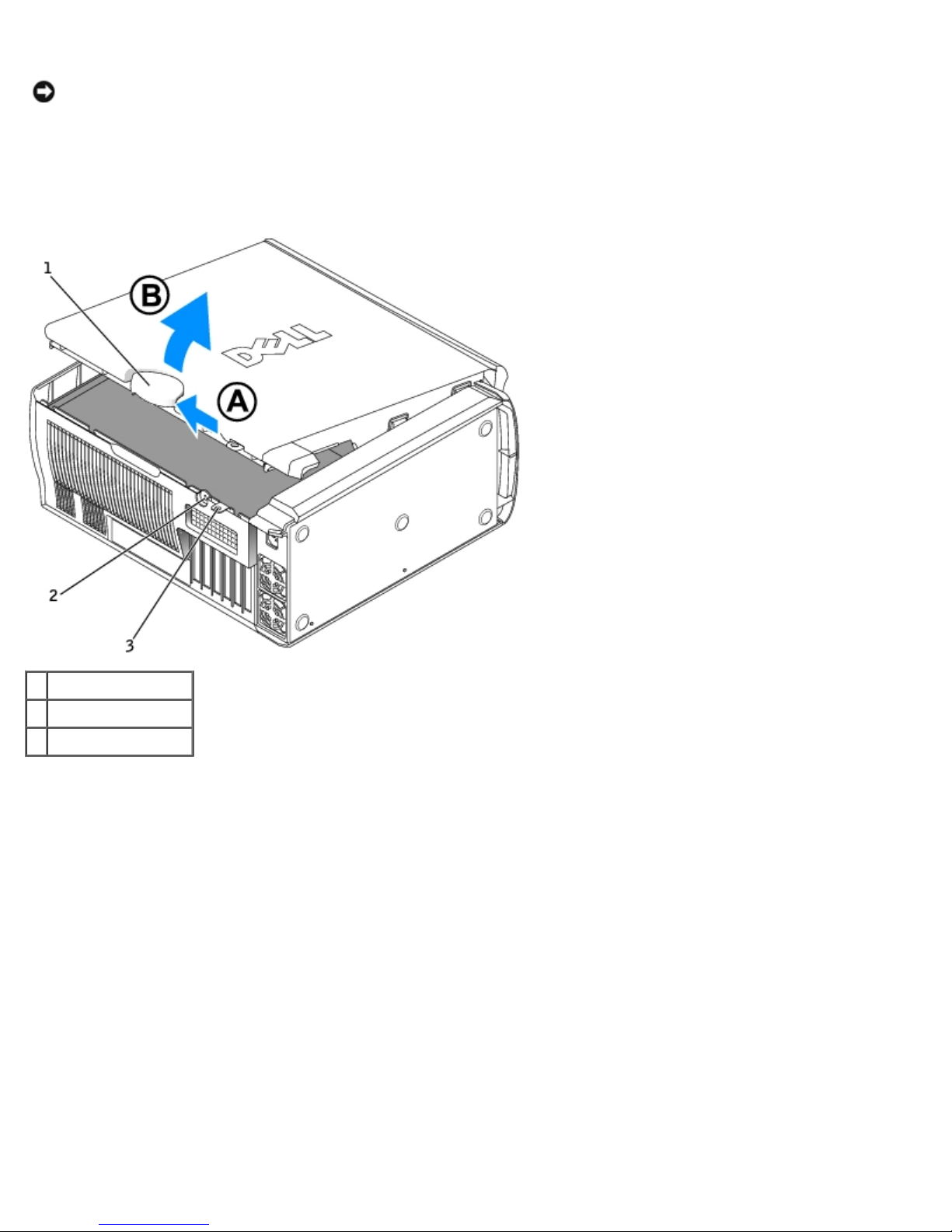
Removing and Replacing Parts: Dell Precision Workstation 470 and 670 Computers User's Guide
NOTICE: Ensure that sufficient space exists to accommodate the open cover—at least 30 cm (1 ft) of desk top space.
3. Slide the cover release latch toward the top of the computer.
4. Raise the cover, and pivot it toward the front of the computer.
Dell Precision 670 Workstation
1 cover release latch
2 security cable slot
3 padlock ring
Dell Precision 470 Workstation
file:///T|/htdocs/systems/ws670/EN/ug_en/before.htm[3/20/2013 9:31:52 AM]
Page 63
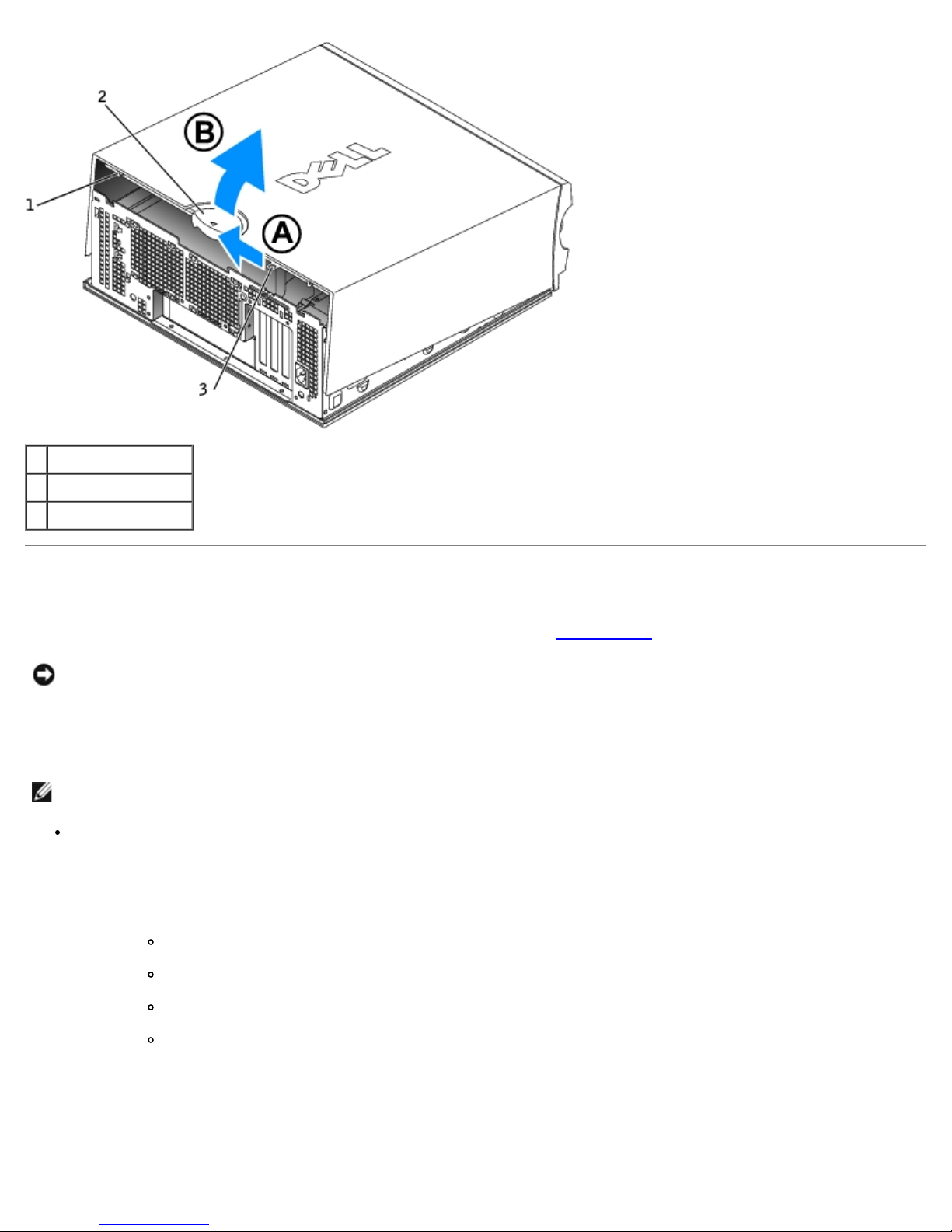
Removing and Replacing Parts: Dell Precision Workstation 470 and 670 Computers User's Guide
1 security cable slot
2 cover release latch
3 padlock ring
Memory
For information on the type of memory supported by your computer, see "Specifications."
NOTICE: Before you install new memory modules, download the most recent BIOS for your computer from the Dell™
Support website at support.dell.com.
Memory Overview
NOTE: Your computer supports ECC and registered memory.
Memory modules should be installed in pairs of matched size, speed, and rank (1R is single rank and 2R is dual rank).
See the label on the memory module to determine its size, speed rank, and organization. Be sure that your memory
module labels match.
Example: 256MB 1Rx8 PC2-5400R-544-10:
Size = 256 MB
Speed = 5400
Rank = 1R
Organization = x8
file:///T|/htdocs/systems/ws670/EN/ug_en/before.htm[3/20/2013 9:31:52 AM]
Page 64
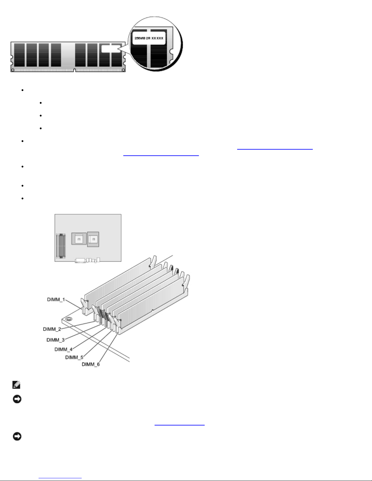
Removing and Replacing Parts: Dell Precision Workstation 470 and 670 Computers User's Guide
Memory modules can be single rank (1R) or dual rank (2R) and should be installed in the following order:
The highest rank memory module in DIMM_1 and DIMM_2
Equal or lower rank memory modules in DIMM_3 and DIMM_4
Single rank (1R) memory modules in DIMM_5 and DIMM_6
If only two memory modules are installed, they must be installed in DIMM_1 and DIMM_2. These connectors are
located on the outside edge of the board (for your Dell Precision 670, see "System Board Components
Dell Precision 470 computer, see "System Board Components
.")
Memory modules should be installed in the following order: connectors DIMM_1 and DIMM_2, DIMM_3 and DIMM_4,
and then DIMM_5 and DIMM_6.
" and for your
If dual-rank modules are installed in DIMM_3 and DIMM_4, then DIMM_5 and DIMM_6 cannot be used.
Dual-rank memory modules are not supported in DIMM_5 and DIMM_6.
NOTE: Memory purchased from Dell is covered under your computer warranty.
NOTICE: If you remove your original memory modules from the computer during a memory upgrade, keep them
separate from any new modules that you may have, even if you purchased the new modules from Dell. If possible, do
not pair an original memory module with a new memory module. Otherwise, your computer may not start properly.
You should install your original memory modules in pairs in connectors DIMM_1 and DIMM_2, connectors DIMM_3 and
DIMM_4, and then DIMM_5 and DIMM6 (see "Memory Overview
NOTICE: If you install more than 4 GB of memory, you must also install a fan to cool the computer. If you do not
install a fan, you will get an error message stating that you must install a fan or remove some memory.
file:///T|/htdocs/systems/ws670/EN/ug_en/before.htm[3/20/2013 9:31:52 AM]
").
Page 65
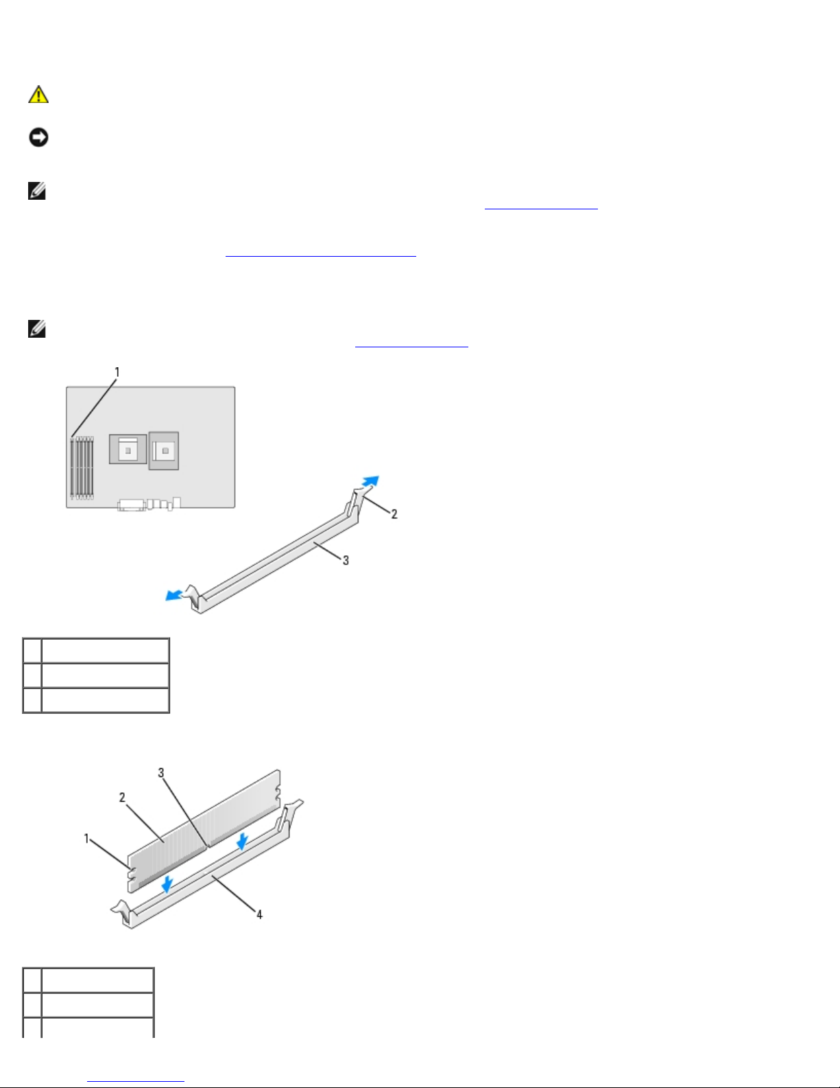
Removing and Replacing Parts: Dell Precision Workstation 470 and 670 Computers User's Guide
Installing Memory
CAUTION: Before you begin any of the procedures in this section, follow the safety instructions located in
the Product Information Guide.
NOTICE: To prevent static damage to components inside your computer, discharge static electricity from your body
before you touch any of your computer's electronic components. You can do so by touching an unpainted metal surface
on the computer chassis.
NOTE: If you have incorrectly installed memory, when you start your computer you will receive an error message.
Press <F2> to enter system setup and help identify the error. See "Memory Overview
guidelines.
1. Follow the procedures in "Removing and Replacing Parts
2. Press out the securing clip at each end of the memory module connector.
NOTE: Memory modules should be installed in the following order: connectors DIMM_1 and DIMM_2, DIMM_3 and
DIMM_4, and then DIMM_5 and DIMM_6. See "Memory Overview
."
" for information on installation
" for information on installation guidelines.
1 DIMM_1 connector
2 securing clips (2)
3 connector
3. Align the notch on the bottom of the module with the crossbar in the connector.
1 cutouts (2)
2 memory module
3 notch
file:///T|/htdocs/systems/ws670/EN/ug_en/before.htm[3/20/2013 9:31:52 AM]
Page 66
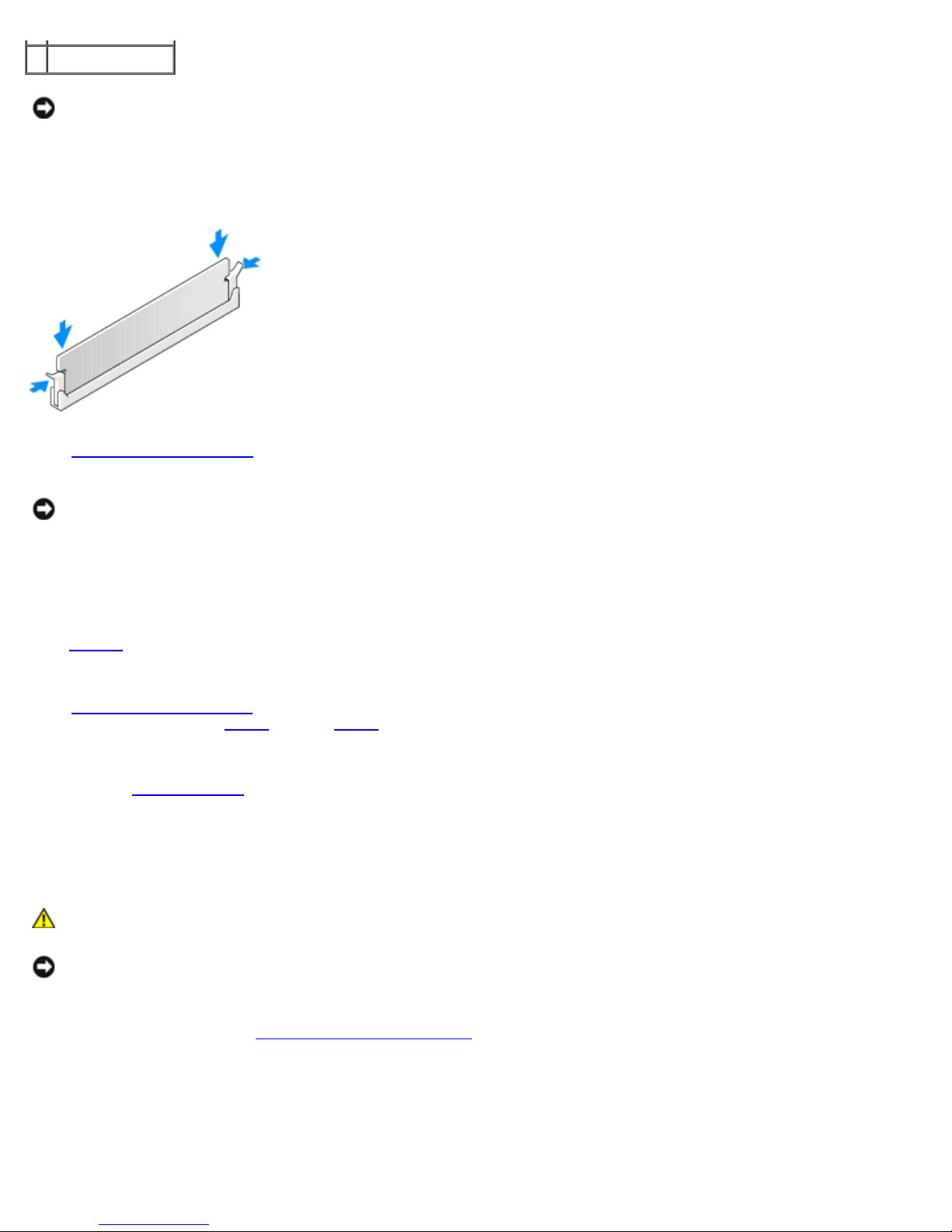
Removing and Replacing Parts: Dell Precision Workstation 470 and 670 Computers User's Guide
4 crossbar
NOTICE: To avoid damage to the memory module, press the module straight down into the connector while you apply
equal force to each end of the module.
4. Insert the module into the connector until the module snaps into position.
If you insert the module correctly, the securing clips snap into the cutouts at each end of the module.
5. Close the computer cover.
NOTICE: To connect a network cable, first plug the cable into the network wall jack and then plug it into the computer.
6. Connect your computer and devices to electrical outlets, and turn them on.
7. Press <F2> to enter system setup and check the value for System Memory.
The value of System Memory should reflect the newly installed memory. Verify the new total. If it is correct, skip to
step 10.
8. If the memory total is incorrect, turn off and disconnect your computer and devices from their electrical outlets.
9. Open the computer cover and check the installed memory modules to ensure that they are seated properly in their
sockets. Then repeat step 5
10. When the System Memory total is correct, press <Esc> to exit system setup.
11. Run the Dell Diagnostics
through step 7.
to verify that the memory modules are operating properly.
Removing Memory
CAUTION: Before you begin any of the procedures in this section, follow the safety instructions located in
the Product Information Guide.
NOTICE: To prevent static damage to components inside your computer, discharge static electricity from your body
before you touch any of your computer's electronic components. You can do so by touching an unpainted metal surface
on the computer chassis.
1. Follow the procedures in "Removing and Replacing Parts
2. Press out the securing clip at each end of the memory module connector.
3. Grasp the module and pull up.
If the module is difficult to remove, gently ease the module back and forth to remove it from the connector.
file:///T|/htdocs/systems/ws670/EN/ug_en/before.htm[3/20/2013 9:31:52 AM]
."
Page 67
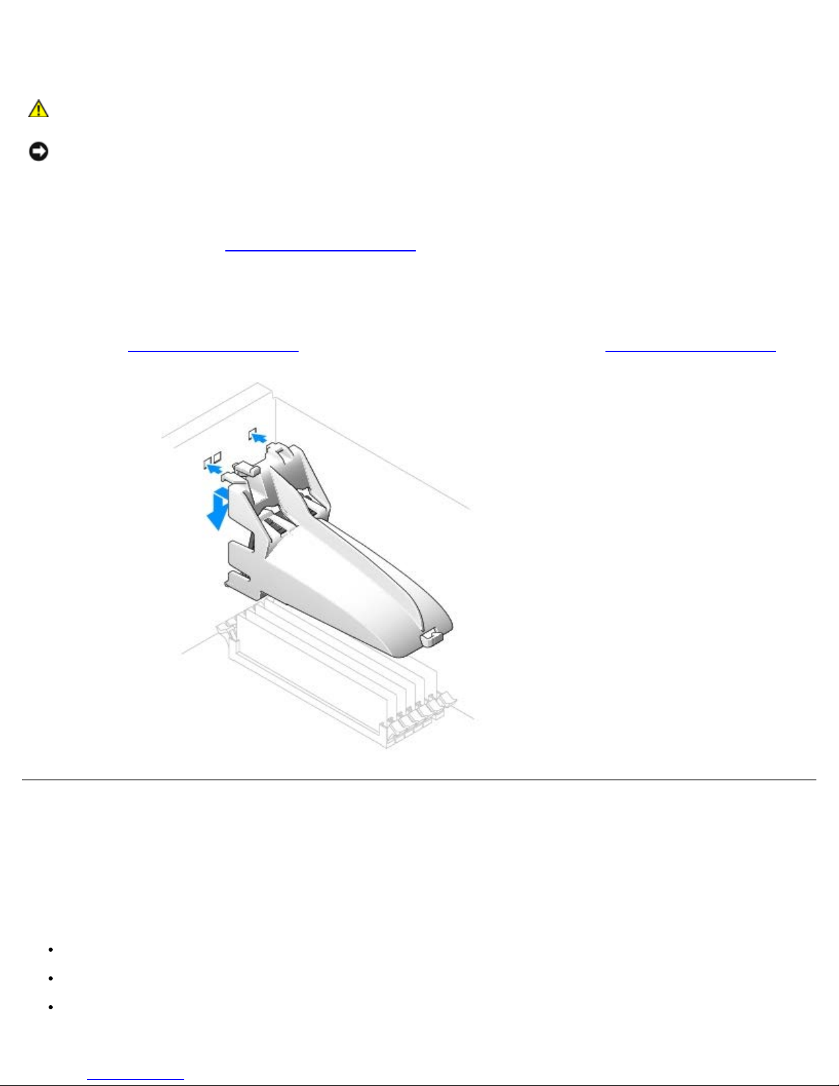
Removing and Replacing Parts: Dell Precision Workstation 470 and 670 Computers User's Guide
Memory Fan and Shroud
CAUTION: Before you begin any of the procedures in this section, follow the safety instructions located in
the Product Information Guide.
NOTICE: If you install more than 4 GB of memory, you must also install a fan to cool the computer. If you do not
install a fan, you will get an error message stating that you must install a fan or remove some memory.
Installing the Memory Fan and Shroud
1. Follow the procedures in "Removing and Replacing Parts."
2. Align the tabs on the back of the shroud with the back of computer.
3. Insert the tabs and lower the shroud in place over the memory modules.
4. Connect the fan cable to the memory fan connector labeled "FAN_MEM" on the system board (for your Dell Precision
670, see "System Board Components
" and for your Dell Precision 470 computer, see "System Board Components").
Drives for the Dell Precision 670 Computer
Overview
Your computer supports:
Three hard drives (Serial ATA and SCSI)
One floppy drive (optional)
Three CD or DVD drives (One bay may be used for an additional hard drive using an add-in bay bracket.)
file:///T|/htdocs/systems/ws670/EN/ug_en/before.htm[3/20/2013 9:31:52 AM]
Page 68

Removing and Replacing Parts: Dell Precision Workstation 470 and 670 Computers User's Guide
1 floppy drive (optional)
2 CD/DVD drive(s)
3 hard drive(s)
Connecting Cables
When you connect two IDE devices to a single IDE interface cable and configure them for the cable select setting, the device
attached to the last connector on the interface cable is the primary or boot device (drive 0), and the device attached to the
middle connector on the interface cable is the secondary device (drive 1). See the drive documentation in your upgrade kit for
information on configuring devices for the cable select setting.
Since cable select is the default setting, any additional drives that are installed do not need to be set as a primary or
secondary drive.
Hard drives should be connected to the connector labeled SATA_0 and SATA_1.
IDE CD/DVD drives should be connected to the connector labeled IDE1 and IDE2.
When you install a drive, you connect two cables—a DC power cable and a data cable—to the back of the drive and to the
system board. Some drives may also have an audio connector; one end of the audio cable attaches to the drive connector
and the other attaches to the system board.
Drive Connectors
IDE Drive Connector Serial ATA Connector
file:///T|/htdocs/systems/ws670/EN/ug_en/before.htm[3/20/2013 9:31:52 AM]
Page 69
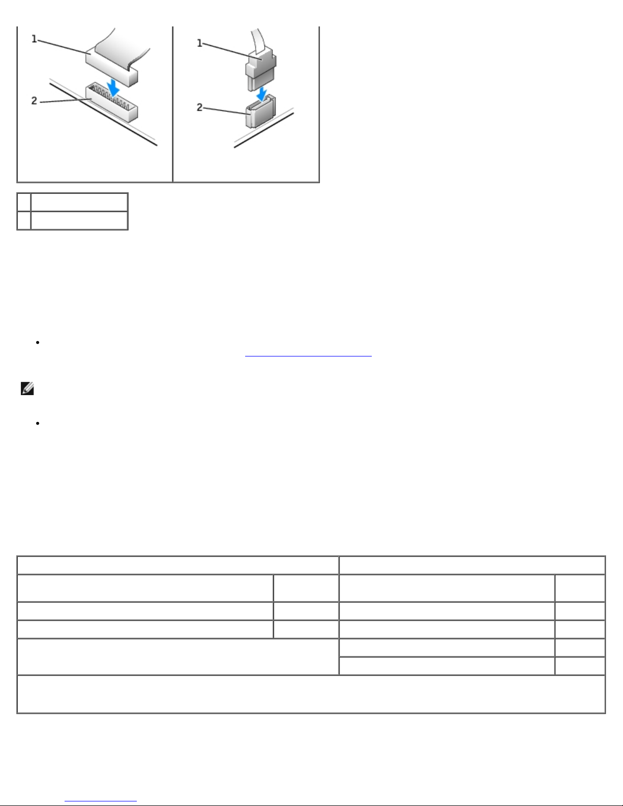
Removing and Replacing Parts: Dell Precision Workstation 470 and 670 Computers User's Guide
1 interface cable
2 interface connector
When connecting and disconnecting a serial ATA cable, hold the cable by the connector at each end.
SCSI Device Installation Guidelines
This section describes how to configure and install SCSI devices in your computer. To install a SCSI device, you can use one
or both of the following SCSI controllers:
The SCSI connector on the system board. To locate the SCSI system board connector, see the system board illustration
(for the Dell Precision 670 computer, see "System Board Components
NOTE: The system board SCSI controller supports hard drives only. Do not connect CD or DVD drives, tape drives, or
DAT drives.
A SCSI controller card installed in your computer.
") or the interior service label.
SCSI ID Numbers
Internal SCSI devices must have a unique SCSI ID number from 0 to 15. If you are using the SCSI connector on the system
board and a SCSI controller card installed in your computer, you have two separate SCSI buses operating. Each SCSI bus has
a set of SCSI ID numbers from 0 to 15.
When SCSI devices are shipped from the factory, the default SCSI ID numbers are assigned as shown in the following table.
System Board Controller Controller Card
Device ID Device ID
Controller 7 Controller 7
Boot hard drive 0 Boot hard drive 0
CD or DVD drive 5
tape or DAT drive 6
NOTE: There is no requirement that SCSI ID numbers be assigned sequentially or that devices be attached to the cable in
order by ID number. If two or more devices use the same ID, your computer may hang during POST and in SCSI BIOS.
SCSI devices installed by Dell are configured correctly during the manufacturing process. You do not need to set the SCSI ID
for these SCSI devices.
If you attach additional optional SCSI devices, see the documentation for each device for information about setting the
file:///T|/htdocs/systems/ws670/EN/ug_en/before.htm[3/20/2013 9:31:52 AM]
Page 70

Removing and Replacing Parts: Dell Precision Workstation 470 and 670 Computers User's Guide
appropriate SCSI ID number.
NOTICE: Dell recommends that you use only SCSI cables purchased from Dell. Cables purchased elsewhere are not
guaranteed to work with Dell computers.
Device Termination
SCSI logic requires that termination be enabled for the two devices at opposite ends of the SCSI chain and disabled for all
devices in between.
It is recommended that you use terminated cables and that you disable termination on all devices. See the documentation
provided with any optional SCSI device you purchase for information on disabling termination on the device.
General Guidelines
Follow these general guidelines when installing SCSI devices in your computer:
Although you install SCSI devices essentially the same way as other devices, their configuration requirements are
different. For details on configuring your particular SCSI subsystem, see the documentation for your SCSI devices
and/or your host adapter card.
Configure the device for a SCSI ID number and disable termination, if necessary.
To use an external SCSI device, you must have a SCSI controller card installed in your computer. Connect one end of
the external SCSI cable to the connector on the back of the SCSI device. Attach the other end of the external SCSI
cable to the connector on the controller card installed in the computer.
After you install a SCSI hard drive, Primary Drive 0 and Primary Drive 1 should be set to None in system setup if
no IDE hard drives are installed. If you have any IDE devices on the second IDE channel, such as a CD or tape drive,
Secondary Drive 0 and/or Secondary Drive 1 should be set to Auto.
To partition and format SCSI hard drives, you may need to use programs other than those provided with the operating
system. See the documentation that came with your SCSI software drivers for information on installing the appropriate
drivers and preparing your SCSI hard drive for use.
SCSI Cables
Ultra 320, Ultra 160/m, and Ultra2/Wide LVD drives (typically hard drives) both use a 68-pin cable. One end of the cable
attaches to the SCSI connector on the system board or the SCSI controller card installed in your computer. The remaining
connectors on the cable attach to the various drives.
Narrow SCSI drives (tape drives, CD drives, and some hard drives) use a 50-pin cable. One end of this cable attaches to the
SCSI controller card. The remaining connectors on the cable attach to the various Narrow SCSI devices.
NOTICE: Dell recommends that you use only SCSI cables purchased from Dell. Cables purchased elsewhere are not
guaranteed to work with Dell computers.
Hard Drive
CAUTION: Before you begin any of the procedures in this section, follow the safety instructions located in
the Product Information Guide.
NOTICE: To avoid damage to the drive, do not set it on a hard surface. Instead, set the drive on a surface, such as a
foam pad, that will sufficiently cushion it.
1. If you are replacing a hard drive that contains data you want to keep, back up your files before you begin this
procedure.
2. Follow the procedures in "Removing and Replacing Parts
file:///T|/htdocs/systems/ws670/EN/ug_en/before.htm[3/20/2013 9:31:52 AM]
."
Page 71
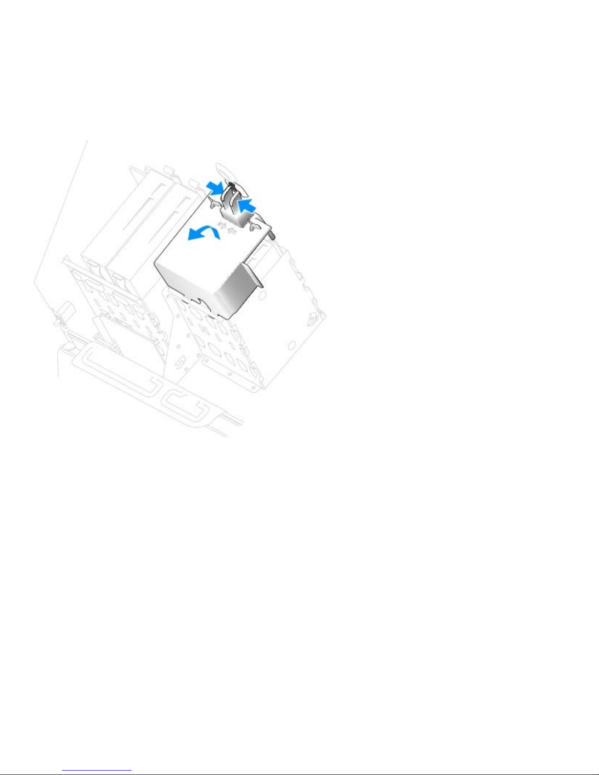
Removing and Replacing Parts: Dell Precision Workstation 470 and 670 Computers User's Guide
Removing a Hard Drive
1. Press in on the top shroud tabs and tilt the shroud back.
2. Lift the shroud away from the hard drive.
3. Disconnect the power and hard-drive cables from the drive.
4. Press in on the tabs on each side of the drive and slide the drive up and out.
file:///T|/htdocs/systems/ws670/EN/ug_en/before.htm[3/20/2013 9:31:52 AM]
Page 72
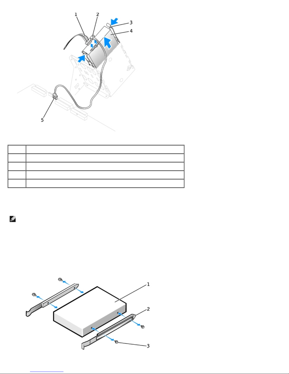
Removing and Replacing Parts: Dell Precision Workstation 470 and 670 Computers User's Guide
1 power cable
2 hard-drive cable
3 tabs (2)
4 hard drive
5 system board connector
Installing a Hard Drive
NOTE: SATA2_0 is the bootable connector.
1. Unpack the replacement hard drive, and prepare it for installation.
2. Check the documentation for the drive to verify that it is configured for your computer.
3. If your replacement hard drive does not have the bracket rails attached, remove the rails from the old drive by
removing the two screws that secure each rail to the drive. Attach the bracket rails to the new drive by aligning the
screw holes on the drive with the screw holes on the bracket rails and then inserting and tightening all four screws (two
screws on each rail).
file:///T|/htdocs/systems/ws670/EN/ug_en/before.htm[3/20/2013 9:31:52 AM]
Page 73
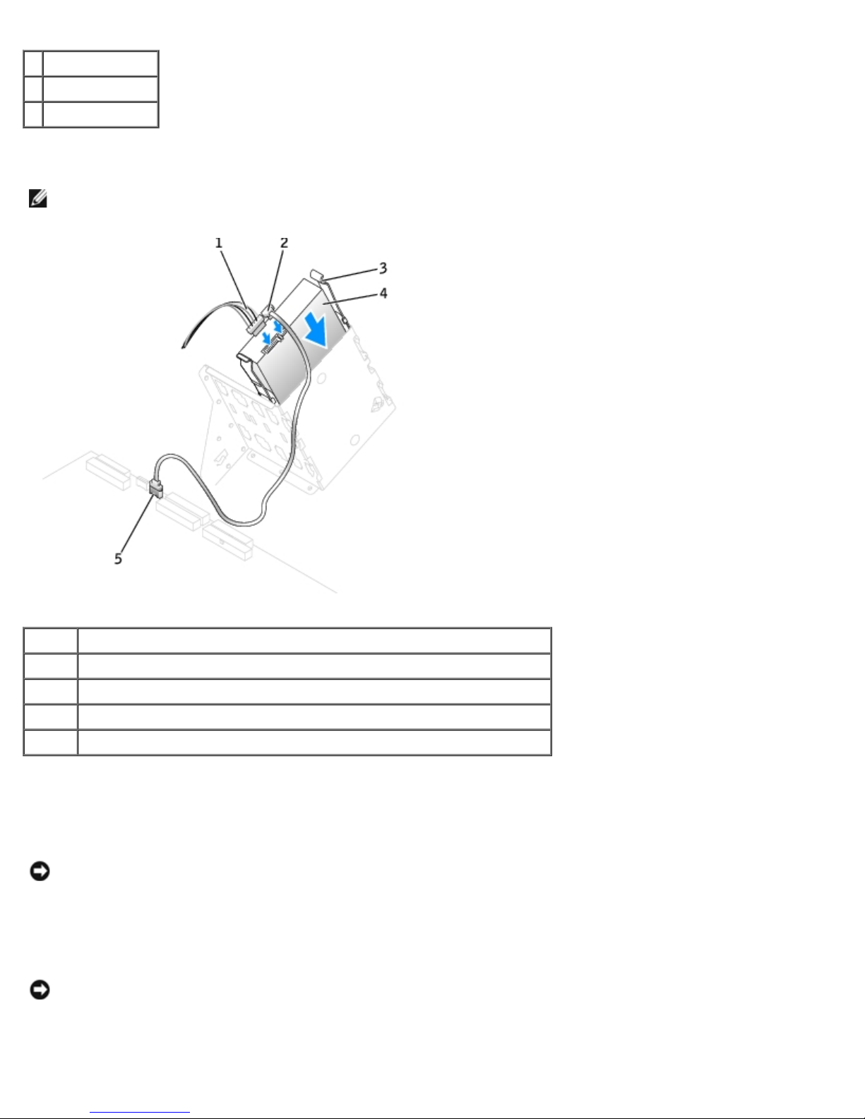
Removing and Replacing Parts: Dell Precision Workstation 470 and 670 Computers User's Guide
1 drive
2 bracket rails (2)
3 screws (4)
4. Gently slide the drive into place until the tabs securely click into position.
NOTE: If you are installing a hard drive in the lower bay, place the drive in the bay so that the power connector is on
the left-hand side (opposite of the top hard drive).
1 power cable
2 hard-drive cable
3 tabs (2)
4 hard drive
5 system board connector
5. If you are installing a drive that has its own controller card, install the controller card in an expansion slot.
See the documentation that accompanied the drive and controller card to verify that the configuration is correct for
your computer.
NOTICE: Match the colored strip on the cable with pin 1 on the drive (pin 1 is marked as "1").
6. Connect the power and hard-drive cables to the drive.
7. Ensure that all connectors are properly cabled and firmly seated.
NOTICE: When replacing the hard-drive shroud, ensure that all the cables are properly routed.
8. Insert the bottom tabs of the shroud into the holes on the drive cage and rotate the shroud up.
9. Press in on the top tabs and lock them into place.
file:///T|/htdocs/systems/ws670/EN/ug_en/before.htm[3/20/2013 9:31:52 AM]
Page 74
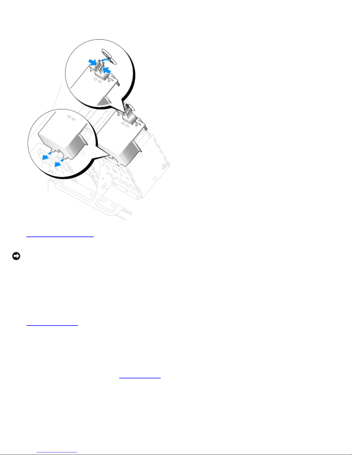
Removing and Replacing Parts: Dell Precision Workstation 470 and 670 Computers User's Guide
10. Gently press on the shroud to ensure that it is secure.
11. Close the computer cover.
NOTICE: To connect a network cable, first plug the cable into the network wall jack and then plug it into the computer.
12. Connect your computer and devices to electrical outlets, and turn them on.
See the documentation that came with the drive for instructions on installing any software required for drive operation.
13. If the drive you just installed is the primary drive, insert a bootable medium into your boot drive.
14. Turn on the computer.
15. Enter system setup
16. After you have updated the system settings, exit system setup, and restart the computer.
17. Partition and logically format your drive before you proceed to the next step.
See the documentation for your operating system for instructions.
18. Test the hard drive by running the Dell Diagnostics
19. If the drive you just installed is the primary drive, install your operating system on the hard drive.
, and update the your drive configuration.
.
Floppy Drive (Optional)
file:///T|/htdocs/systems/ws670/EN/ug_en/before.htm[3/20/2013 9:31:52 AM]
Page 75
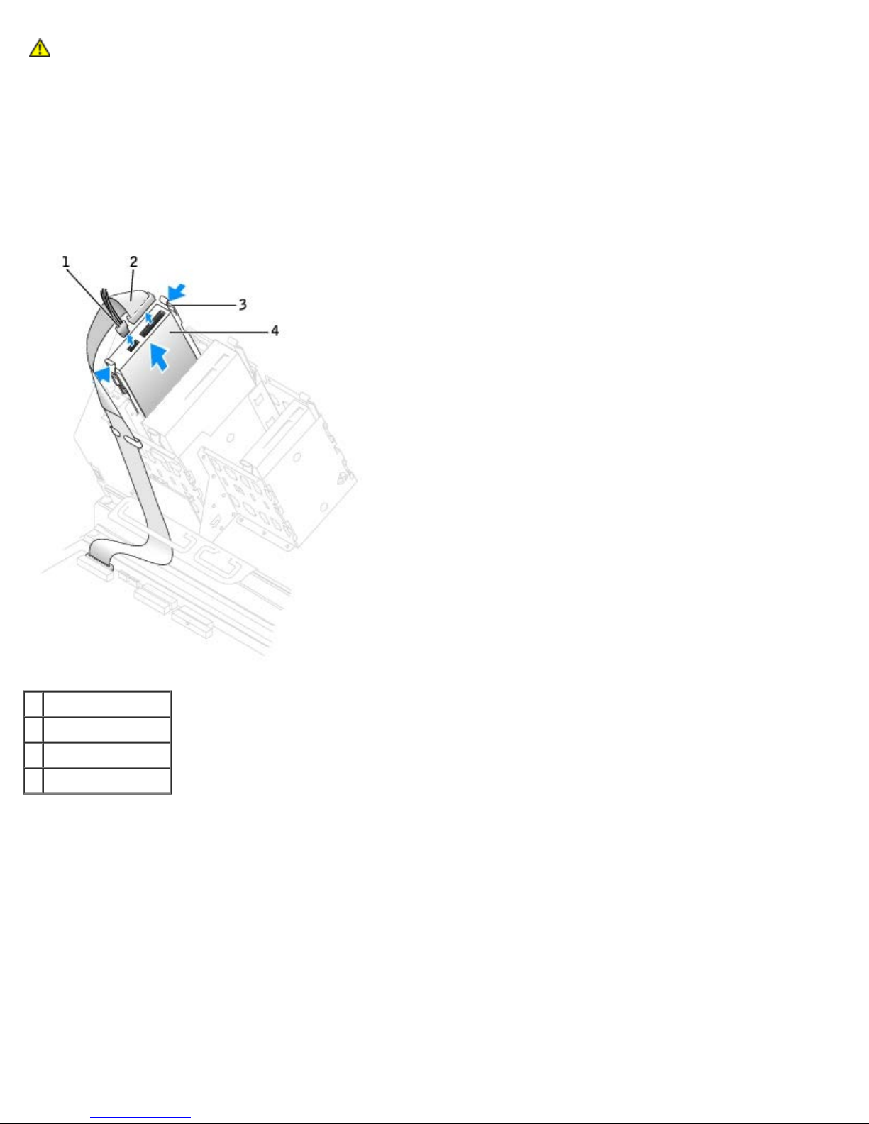
Removing and Replacing Parts: Dell Precision Workstation 470 and 670 Computers User's Guide
CAUTION: Before you begin any of the procedures in this section, follow the safety instructions located in
the Product Information Guide.
Removing a Floppy Drive
1. Follow the procedure in "Removing and Replacing Parts."
2. Disconnect the power and floppy-drive cables from the back of the floppy drive.
3. Press inward on the two tabs on the sides of the drive, slide the drive upward, and remove it from the floppy-drive
bay.
1 power cable
2 floppy-drive cable
3 tabs (2)
4 floppy drive
Installing a Floppy Drive
1. If you are replacing a drive and the new drive does not have the bracket rails attached, remove the rails from the old
drive by removing the two screws that secure each rail to the drive. Attach the bracket to the new drive by aligning the
screw holes on the drive with the screw holes on the bracket rails and then inserting and tightening all four screws (two
screws on each rail).
file:///T|/htdocs/systems/ws670/EN/ug_en/before.htm[3/20/2013 9:31:52 AM]
Page 76
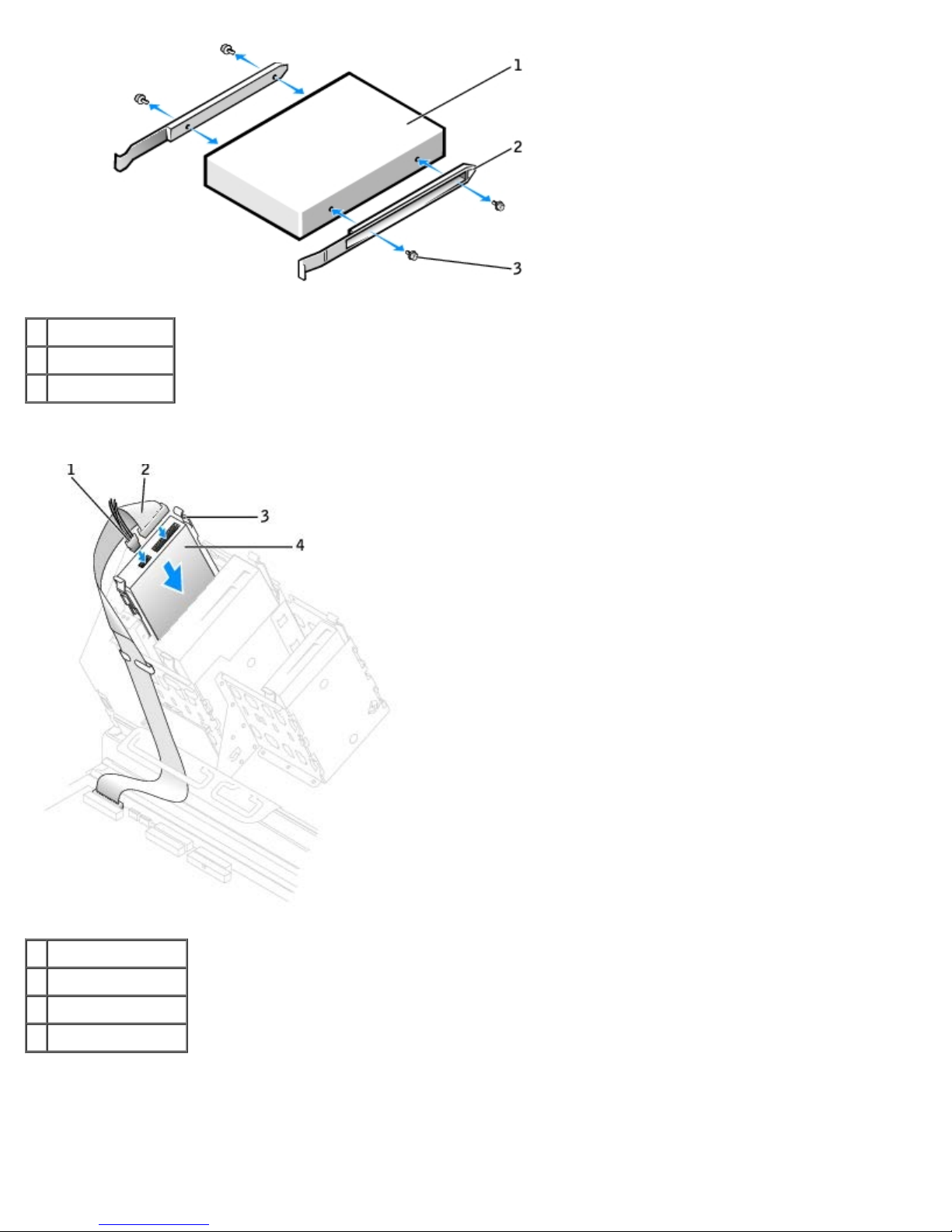
Removing and Replacing Parts: Dell Precision Workstation 470 and 670 Computers User's Guide
1 drive
2 bracket rails (2)
3 screws (4)
2. Gently slide the drive into place until the tabs securely click into position.
1 power cable
2 floppy-drive cable
3 tabs (2)
4 floppy drive
3. Attach the power and floppy-drive cables to the floppy drive.
4. If you are installing a new floppy drive rather than replacing a drive, remove the front-panel inserts.
From inside the drive bay, gently press on each side of the insert until it pops out.
file:///T|/htdocs/systems/ws670/EN/ug_en/before.htm[3/20/2013 9:31:52 AM]
Page 77
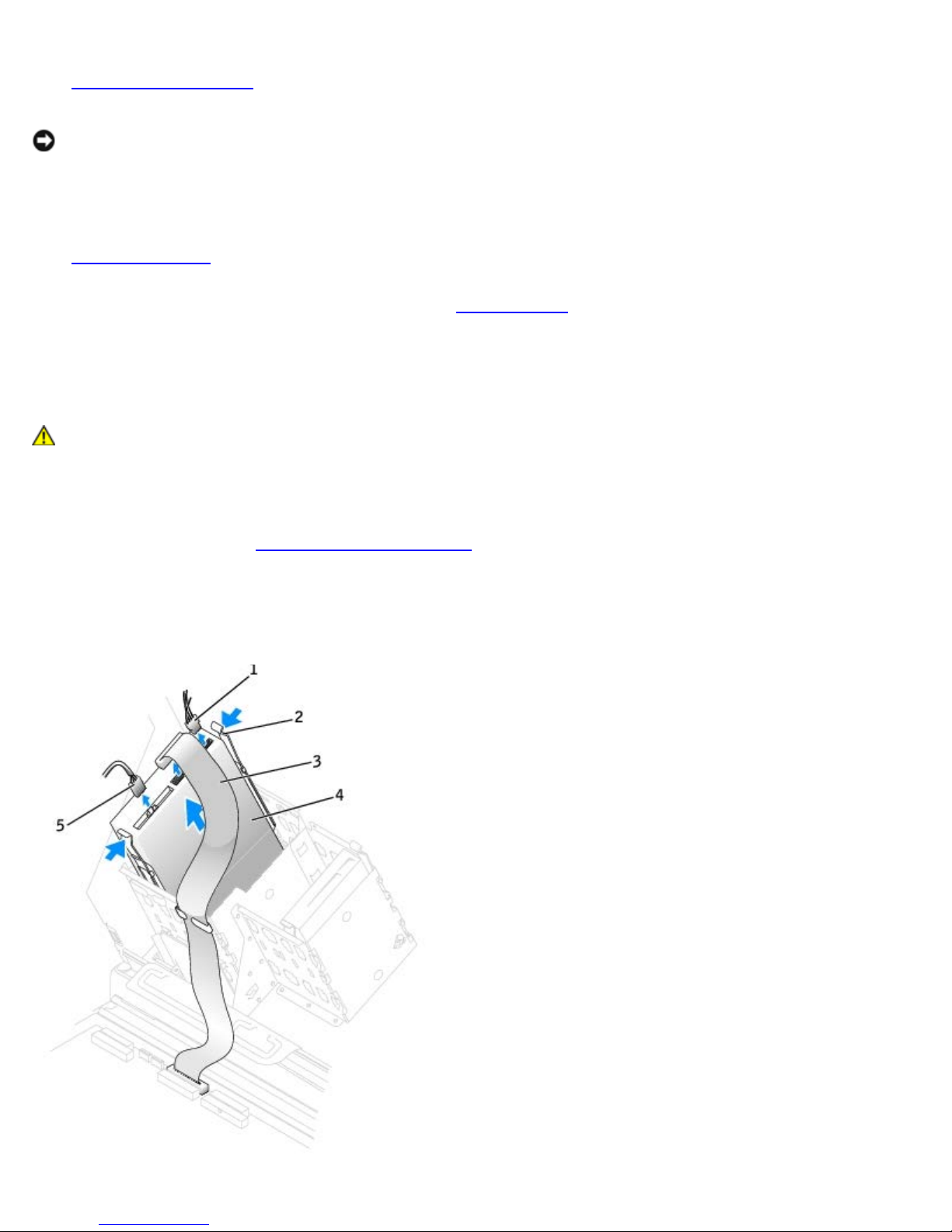
Removing and Replacing Parts: Dell Precision Workstation 470 and 670 Computers User's Guide
5. Check all cable connections, and fold cables out of the way to provide airflow for the fan and cooling vents.
6. Close the computer cover.
NOTICE: To connect a network cable, first plug the cable into the network wall jack and then plug it into the computer.
7. Connect your computer and devices to electrical outlets, and turn them on.
See the documentation that came with the drive for instructions on installing any software required for drive operation.
8. Enter system setup
floppy drive.
9. To verify that your computer works correctly, run the Dell Diagnostics.
and update the appropriate Diskette Drive A option to reflect the size and capacity of your new
CD/DVD Drive
CAUTION: Before you begin any of the procedures in this section, follow the safety instructions located in
the Product Information Guide.
Removing a CD/DVD Drive
1. Follow the procedures in "Removing and Replacing Parts."
2. Disconnect the power and CD/DVD drive cables from the drive.
3. Press inward on the two tabs on the sides of the drive, and then slide the drive upward and remove it from the drive
bay.
file:///T|/htdocs/systems/ws670/EN/ug_en/before.htm[3/20/2013 9:31:52 AM]
Page 78
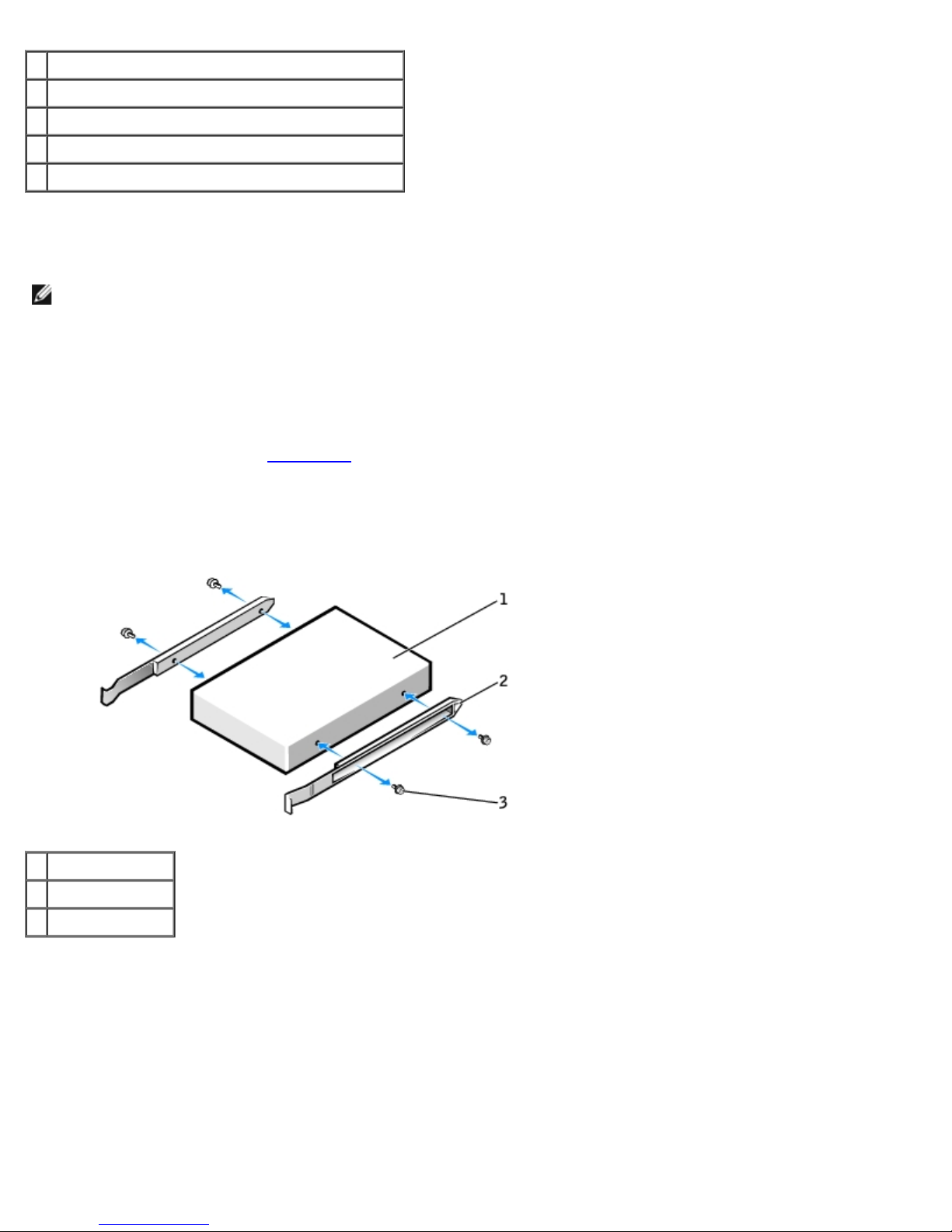
Removing and Replacing Parts: Dell Precision Workstation 470 and 670 Computers User's Guide
1 power cable
2 tabs (2)
3 CD/DVD drive cable
4 CD/DVD drive
5 audio cable (some drives do not have this cable)
Installing a CD/DVD Drive
NOTE: A fourth hard drive can be added to the CD/DVD bay using an add-in bay bracket. Contact Dell to order a
bracket.
1. If you are installing a new drive, unpack the drive and prepare it for installation.
Check the documentation that accompanied the drive to verify that the drive is configured for your computer. If you are
installing an IDE drive, configure the drive for the cable select setting.
2. Connect the new drive to the set of rails that are attached to the inside of the cover. If a set of rails is not attached
inside the computer cover, contact Dell
.
3. If you are installing a replacement drive and the new drive does not have the bracket rails attached, remove the rails
from the old drive by removing the two screws that secure each rail to the drive. Attach the bracket to the new drive
by aligning the screw holes on the drive with the screw holes on the bracket rails and then inserting and tightening all
four screws (two screws on each rail).
1 drive
2 bracket rails (2)
3 screws (4)
4. Gently slide the drive into place until the tabs securely click into position.
5. If you are installing a drive that has its own controller card, install the controller card in an expansion slot.
See the documentation that accompanied the drive and controller card to verify that the configuration is correct for
your computer.
6. Connect the power and CD/DVD drive cables to the drive.
If you are adding a drive that has an audio cable, connect the audio cable to the audio connector on the system board.
file:///T|/htdocs/systems/ws670/EN/ug_en/before.htm[3/20/2013 9:31:52 AM]
Page 79
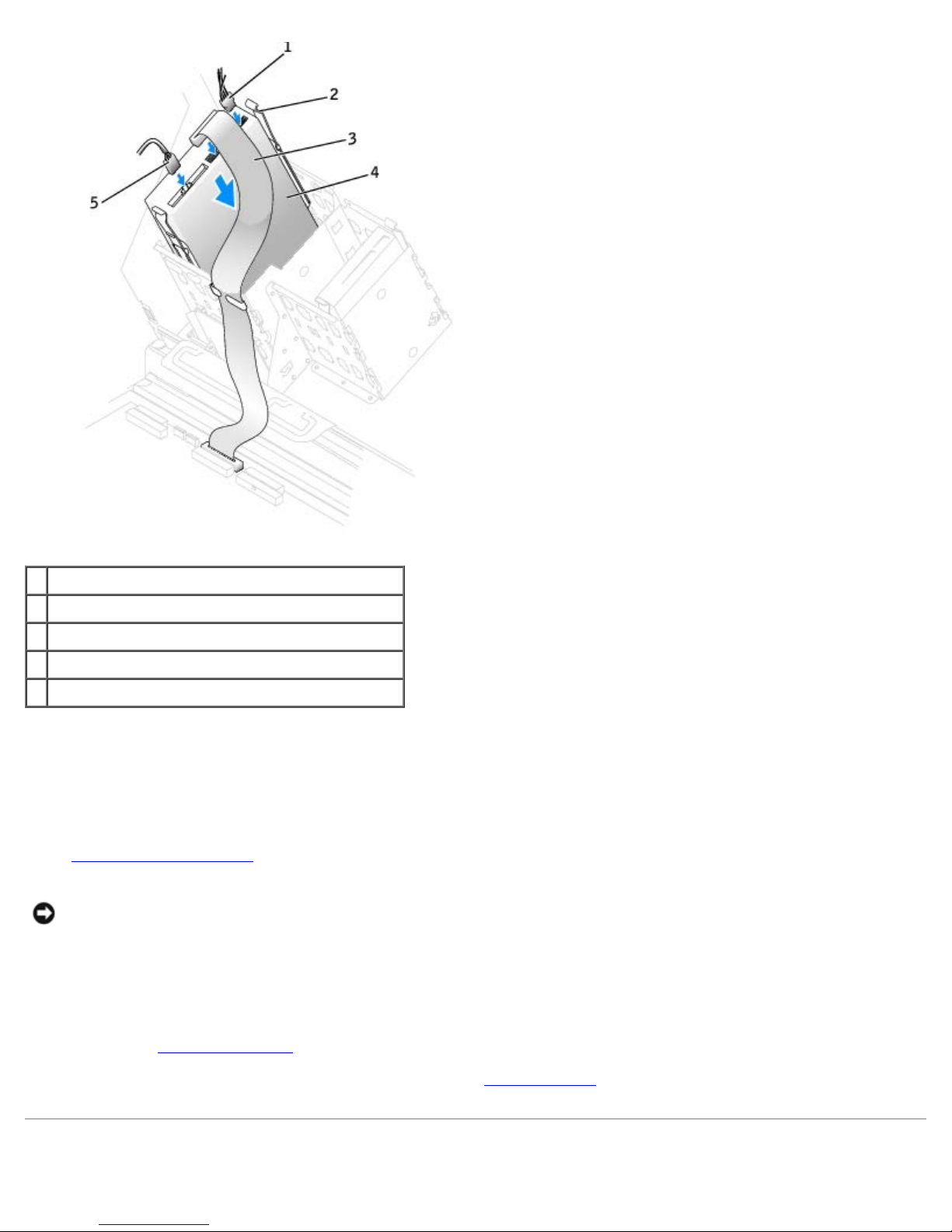
Removing and Replacing Parts: Dell Precision Workstation 470 and 670 Computers User's Guide
1 power cable
2 tabs (2)
3 CD/DVD drive cable
4 CD/DVD drive
5 audio cable (some drives do not have this cable)
7. If you are installing a new CD/DVD drive rather than replacing a drive, remove the
front-panel inserts.
From inside the drive bay, gently press on each side of the insert until it pops out.
8. Check all cable connections, and fold cables out of the way to provide airflow for the fan and cooling vents.
9. Close the computer cover
.
NOTICE: To connect a network cable, first plug the cable into the network wall jack and then plug it into the computer.
10. Connect your computer and devices to electrical outlets, and turn them on.
See the documentation that came with the drive for instructions on installing any software required for drive operation.
11. Update your configuration information by setting the appropriate Drive option (0 or 1) under Drives: Secondary to
Auto. See "Advanced Features
" for more information.
12. Verify that your computer works correctly by running the Dell Diagnostics
file:///T|/htdocs/systems/ws670/EN/ug_en/before.htm[3/20/2013 9:31:52 AM]
.
Page 80
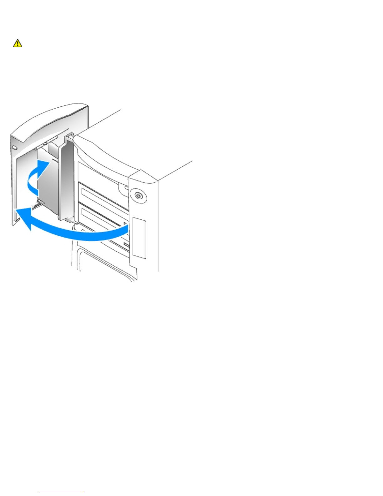
Removing and Replacing Parts: Dell Precision Workstation 470 and 670 Computers User's Guide
Drive Door for the Dell Precision 670 Computer
CAUTION: Before you begin any of the procedures in this section, follow the safety instructions located in
the Product Information Guide.
Removing the Drive Door
1. Open the drive door.
2. Unsnap the top bracket hinge and pull the top of the drive door outward, away from the computer.
file:///T|/htdocs/systems/ws670/EN/ug_en/before.htm[3/20/2013 9:31:52 AM]
Page 81
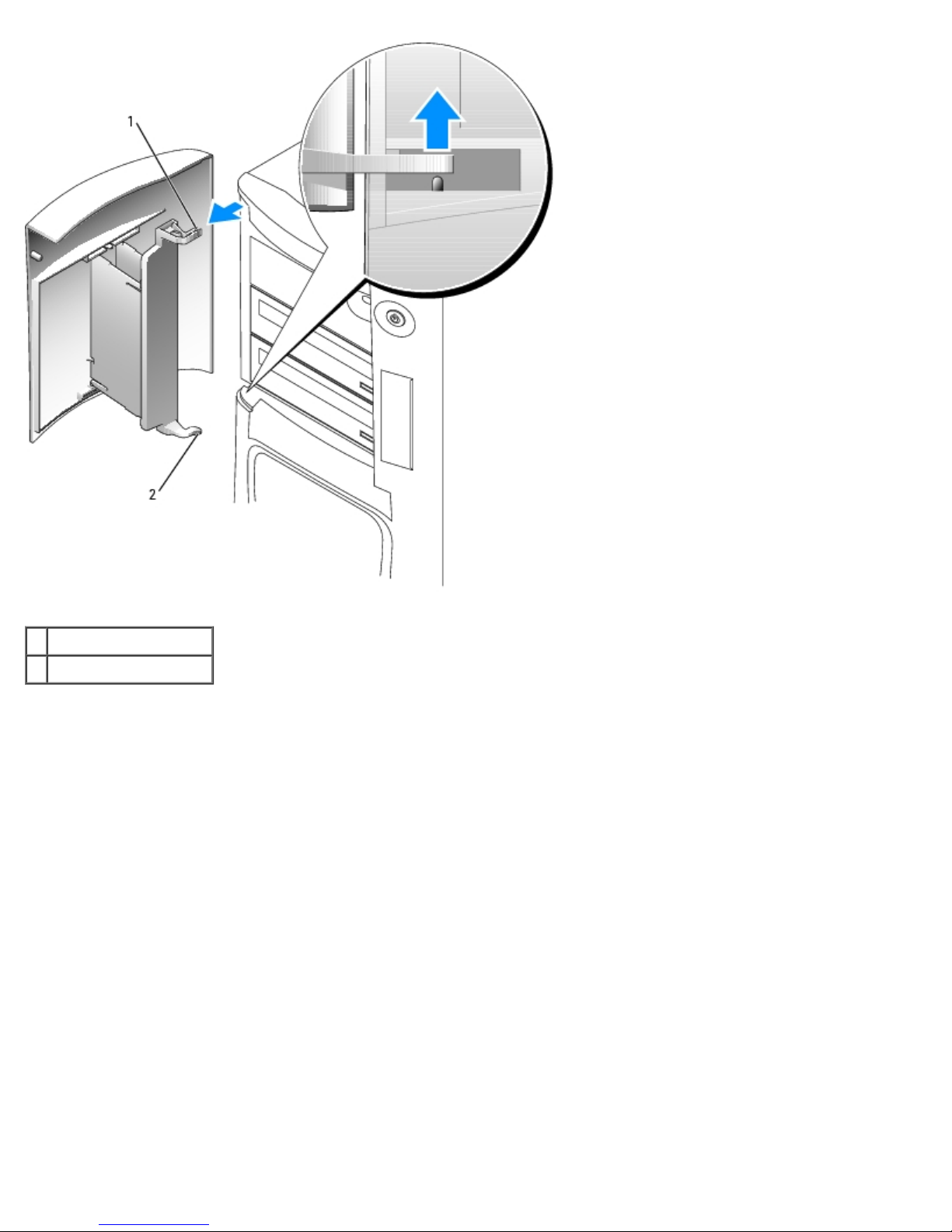
Removing and Replacing Parts: Dell Precision Workstation 470 and 670 Computers User's Guide
1 top bracket hinge
2 bottom bracket hinge
3. Lift the bottom bracket hinge away from the computer.
Replacing the Drive Door
To prevent damage to your computer, the drive door is designed to "break away" from the computer if it is opened too far. If
the drive door detaches from the computer without disassembling, perform the removal procedure in reverse.
If the drive door is open and it is opened too far, instead of breaking away from the computer in one piece, the drive door
may disassemble into several smaller pieces. If the drive door disassembles:
1. If necessary, reattach the door hinges to the door bracket. Ensure that the hinge tabs are away from the door bracket.
file:///T|/htdocs/systems/ws670/EN/ug_en/before.htm[3/20/2013 9:31:52 AM]
Page 82
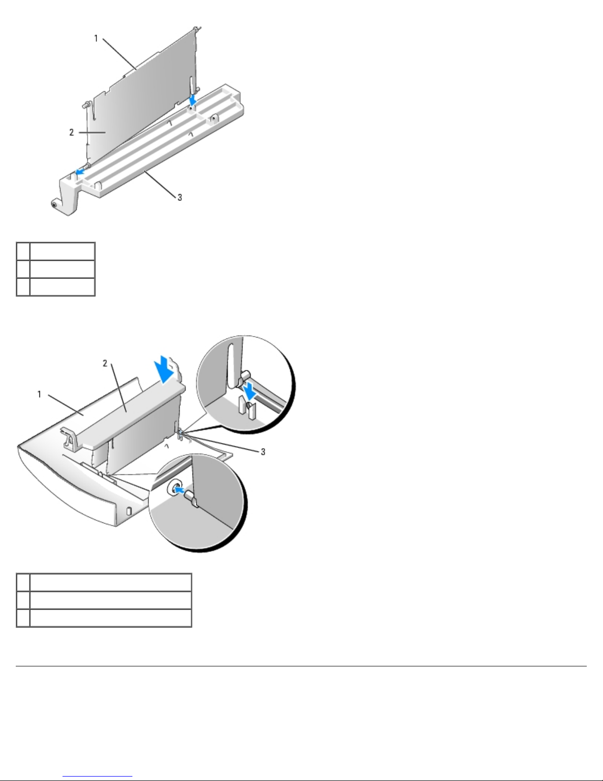
Removing and Replacing Parts: Dell Precision Workstation 470 and 670 Computers User's Guide
1 hinge tab
2 door hinge
3 door bracket
2. Attach the door bracket/door hinge assembly to the door, starting with the lower part of each door hinge.
1 door
2 door bracket/door hinge assembly
3 lower part of the door hinge
3. Attach the drive door to the computer, starting with the bottom bracket hinge.
Drives for the Dell Precision 470 Computer
file:///T|/htdocs/systems/ws670/EN/ug_en/before.htm[3/20/2013 9:31:52 AM]
Page 83
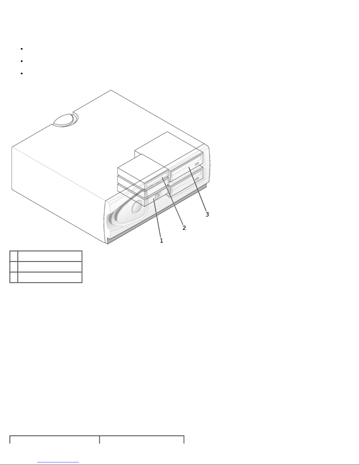
Removing and Replacing Parts: Dell Precision Workstation 470 and 670 Computers User's Guide
Overview
Your computer supports:
Two hard drives (Your computer supports SCSI with an add-in controller and Serial ATA.)
One floppy drive (optional)
Two CD or DVD drives
1 hard drive(s)
2 floppy drive (optional)
3 CD/DVD drive(s)
Connecting Cables
When you connect two IDE devices to a single IDE interface cable and configure them for the cable select setting, the device
attached to the last connector on the interface cable is the primary or boot device (drive 0), and the device attached to the
middle connector on the interface cable is the secondary device (drive 1). See the drive documentation in your upgrade kit for
information on configuring devices for the cable select setting.
Since cable select is the default setting, any additional drives that are installed do not need to be set as a primary or
secondary drive.
Hard drives should be connected to the connector labeled SATA_0 and SATA_1.
IDE CD/DVD drives should be connected to the connector labeled IDE1 and IDE2.
When you install a drive, you connect two cables—a DC power cable and a data cable—to the back of the drive and to the
system board. Some drives may also have an audio connector; one end of the audio cable will attach to the drive connector
and the other will attach to the system board.
Drive Connectors
file:///T|/htdocs/systems/ws670/EN/ug_en/before.htm[3/20/2013 9:31:52 AM]
Page 84
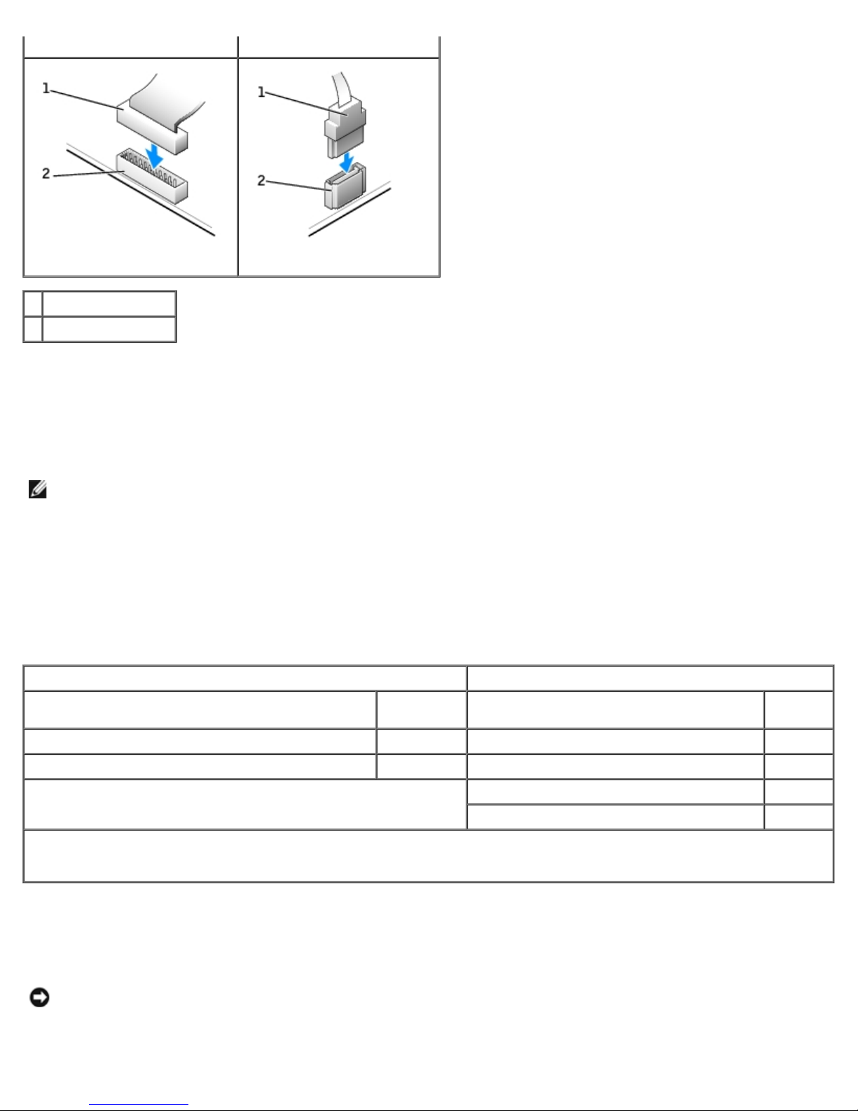
Removing and Replacing Parts: Dell Precision Workstation 470 and 670 Computers User's Guide
IDE Drive Connector Serial ATA Connector
1 interface cable
2 interface connector
When connecting and disconnecting a serial ATA cable, hold the cable by the connector at each end.
SCSI Device Installation Guidelines
This section describes how to configure and install SCSI devices in your computer.
NOTE: The system board SCSI controller supports hard drives only. Do not connect CD or DVD drives, tape drives, or
DAT drives.
SCSI ID Numbers
Internal SCSI devices must have a unique SCSI ID number from 0 to 15. If you are using the SCSI connector on the system
board and a SCSI controller card installed in your computer, you have two separate SCSI buses operating. Each SCSI bus has
a set of SCSI ID numbers from 0 to 15.
When SCSI devices are shipped from the factory, the default SCSI ID numbers are assigned as shown in the following table.
System Board Controller Controller Card
Device ID Device ID
Controller 7 Controller 7
Boot hard drive 0 Boot hard drive 0
CD or DVD drive 5
tape or DAT drive 6
NOTE: There is no requirement that SCSI ID numbers be assigned sequentially or that devices be attached to the cable in
order by ID number. If two or more devices use the same ID, your computer may hang during POST and in SCSI BIOS.
SCSI devices installed by Dell are configured correctly during the manufacturing process. You do not need to set the SCSI ID
for these SCSI devices.
If you attach additional optional SCSI devices, see the documentation for each device for information about setting the
appropriate SCSI ID number.
NOTICE: Dell recommends that you use only SCSI cables purchased from Dell. Cables purchased elsewhere are not
guaranteed to work with Dell computers.
file:///T|/htdocs/systems/ws670/EN/ug_en/before.htm[3/20/2013 9:31:52 AM]
Page 85

Removing and Replacing Parts: Dell Precision Workstation 470 and 670 Computers User's Guide
Device Termination
SCSI logic requires that termination be enabled for the two devices at opposite ends of the SCSI chain and disabled for all
devices in between.
It is recommended that you use terminated cables and that you disable termination on all devices. See the documentation
provided with any optional SCSI device you purchased for information on disabling termination on the device.
General Guidelines
Follow these general guidelines when installing SCSI devices in your computer:
Although you install SCSI devices essentially the same way as other devices, their configuration requirements are
different. For details on configuring your particular SCSI subsystem, see the documentation for your SCSI devices
and/or your host adapter card.
Configure the device for a SCSI ID number and disable termination, if necessary.
To use an external SCSI device, you must have a SCSI controller card installed in your computer. Connect one end of
the external SCSI cable to the connector on the back of the SCSI device. Attach the other end of the external SCSI
cable to the connector on the controller card installed in the computer.
After you install a SCSI hard drive, Primary Drive 0 and Primary Drive 1 should be set to None in system setup if
no EIDE hard drives are installed. If you have any EIDE devices on the second EIDE channel, such as a CD or tape
drive, Secondary Drive 0 and/or Secondary Drive 1 should be set to Auto.
You may need to use programs other than those provided with the operating system to partition and format SCSI hard
drives. See the documentation that came with your SCSI software drivers for information on installing the appropriate
drivers and preparing your SCSI hard drive for use.
SCSI Cables
Ultra 320 (optional on the Dell Precision 470 computer), Ultra 160/m and Ultra2/Wide LVD drives (typically hard drives) both
use a 68-pin cable. One end of the cable attaches to the SCSI connector on the system board or the SCSI controller card
installed in your computer. The remaining connectors on the cable attach to the various drives.
Narrow SCSI drives (tape drives, CD drives, and some hard drives) use a 50-pin cable. One end of this cable attaches to the
SCSI controller card. The remaining connectors on the cable attach to the various Narrow SCSI devices.
NOTICE: Dell recommends that you use only SCSI cables purchased from Dell. Cables purchased elsewhere are not
guaranteed to work with Dell computers.
Hard Drive
CAUTION: Before you begin any of the procedures in this section, follow the safety instructions located in
the Product Information Guide.
NOTICE: To avoid damage to the drive, do not set it on a hard surface. Instead, set the drive on a surface, such as a
foam pad, that will sufficiently cushion it.
Removing a Hard Drive
1. If you are replacing a hard drive that contains data you want to keep, back up your files before you begin this
procedure.
2. Follow the instructions in "Removing and Replacing Parts."
3. Disconnect the power and hard-drive cables from the drive.
file:///T|/htdocs/systems/ws670/EN/ug_en/before.htm[3/20/2013 9:31:52 AM]
Page 86
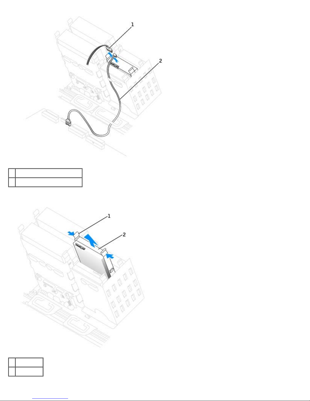
Removing and Replacing Parts: Dell Precision Workstation 470 and 670 Computers User's Guide
1 power cable
2 serial ATA hard-drive cable
4. Press in on the tabs on each side of the drive and slide the drive up and out.
1 tab (2)
2 hard drive
file:///T|/htdocs/systems/ws670/EN/ug_en/before.htm[3/20/2013 9:31:52 AM]
Page 87
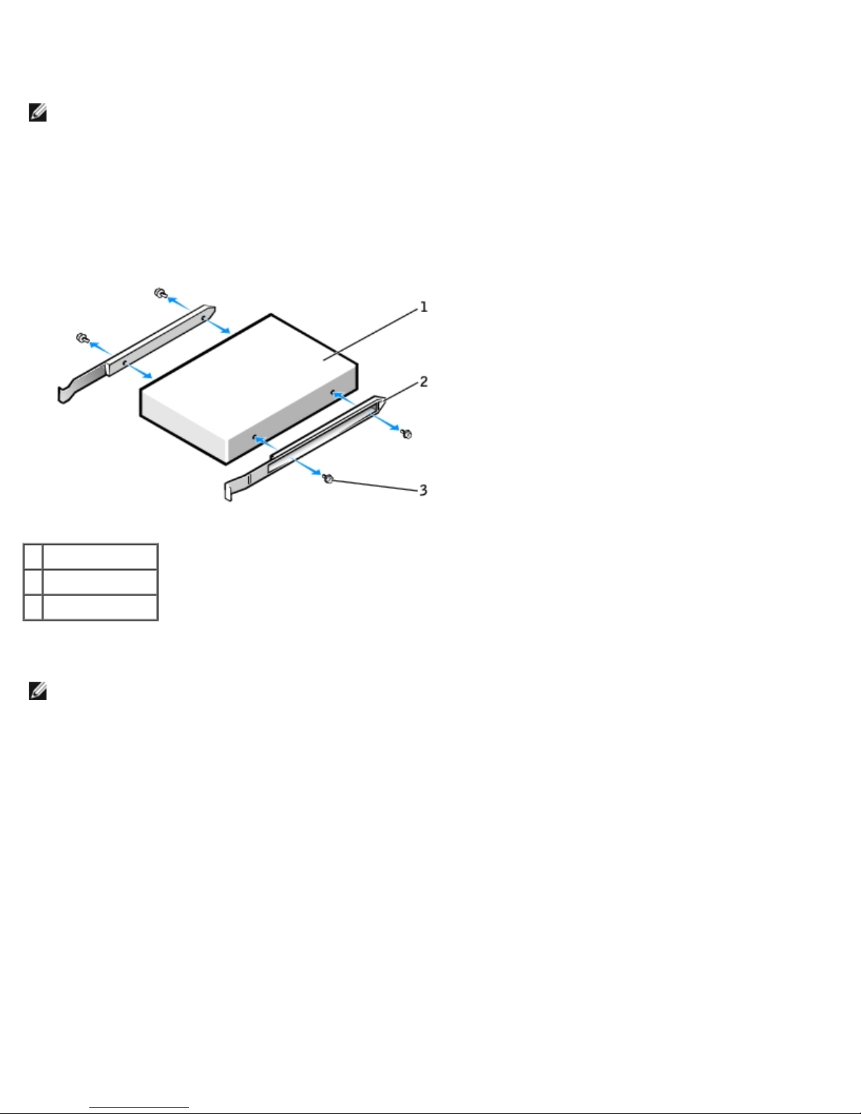
Removing and Replacing Parts: Dell Precision Workstation 470 and 670 Computers User's Guide
Installing a Hard Drive
NOTE: SATA2_0 is the bootable connector.
1. Unpack the replacement hard drive, and prepare it for installation.
2. Check the documentation for the drive to verify that it is configured for your computer.
3. If your replacement hard drive does not have the bracket rails attached, remove the rails from the old drive by
removing the two screws that secure each rail to the drive. Attach the bracket rails to the new drive by aligning the
screw holes on the drive with the screw holes on the bracket rails and then inserting and tightening all four screws (two
screws on each rail).
1 drive
2 bracket rails (2)
3 screws (4)
4. Gently slide the drive into place until the tabs securely click into position.
NOTE: If you are installing a hard drive in the lower bay, the drive should be placed in the bay so that the power
connector is on the left-hand side (opposite of the top hard drive).
file:///T|/htdocs/systems/ws670/EN/ug_en/before.htm[3/20/2013 9:31:52 AM]
Page 88
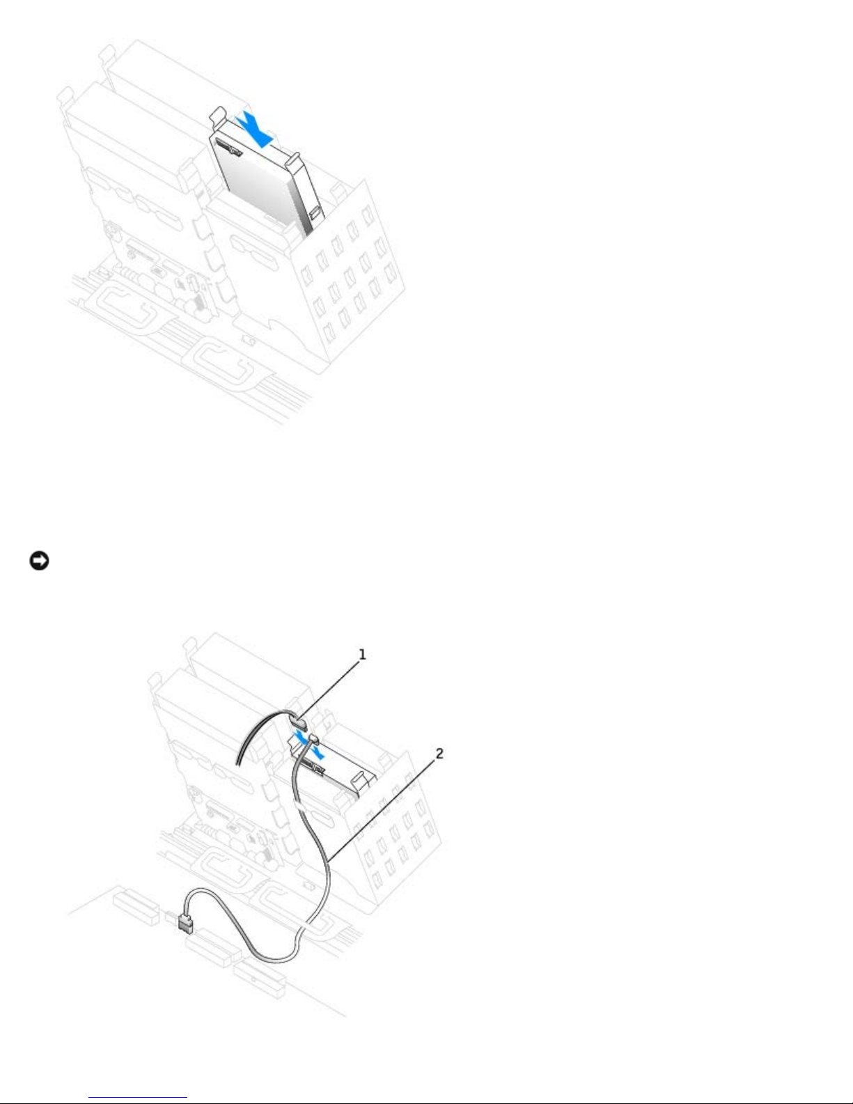
Removing and Replacing Parts: Dell Precision Workstation 470 and 670 Computers User's Guide
5. If you are installing a drive that has its own controller card, install the controller card in an expansion slot.
See the documentation that accompanied the drive and controller card to verify that the configuration is correct for
your computer.
NOTICE: Match the colored strip on the cable with pin 1 on the drive (pin 1 is marked as "1").
6. Connect the power and hard-drive cables to the drive.
file:///T|/htdocs/systems/ws670/EN/ug_en/before.htm[3/20/2013 9:31:52 AM]
Page 89
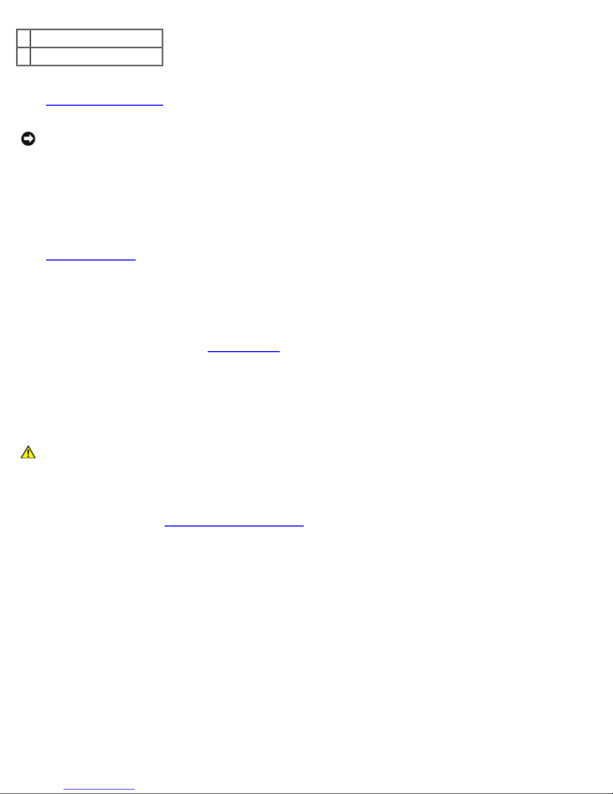
Removing and Replacing Parts: Dell Precision Workstation 470 and 670 Computers User's Guide
1 power cable
2 serial ATA hard-drive cable
7. Ensure that all connectors are properly cabled and firmly seated.
8. Close the computer cover.
NOTICE: To connect a network cable, first plug the cable into the network wall jack and then plug it into the computer.
9. Connect your computer and devices to electrical outlets, and turn them on.
See the documentation that came with the drive for instructions on installing any software required for drive operation.
10. If the drive you just installed is the primary drive, insert a bootable medium into your boot drive.
11. Turn on the computer.
12. Enter system setup
13. After you have updated the system settings, exit system setup, and restart the computer.
14. Partition and logically format your drive before you proceed to the next step.
See the documentation for your operating system for instructions.
15. Test the hard drive by running the Dell Diagnostics
16. If the drive you just installed is the primary drive, install your operating system on the hard drive.
, and update the your drive configuration.
.
Floppy Drive (Optional)
CAUTION: Before you begin any of the procedures in this section, follow the safety instructions located in
the Product Information Guide.
Removing a Floppy Drive
1. Follow the procedures in "Removing and Replacing Parts."
2. Disconnect the power and floppy-drive cables from the back of the floppy drive.
file:///T|/htdocs/systems/ws670/EN/ug_en/before.htm[3/20/2013 9:31:52 AM]
Page 90
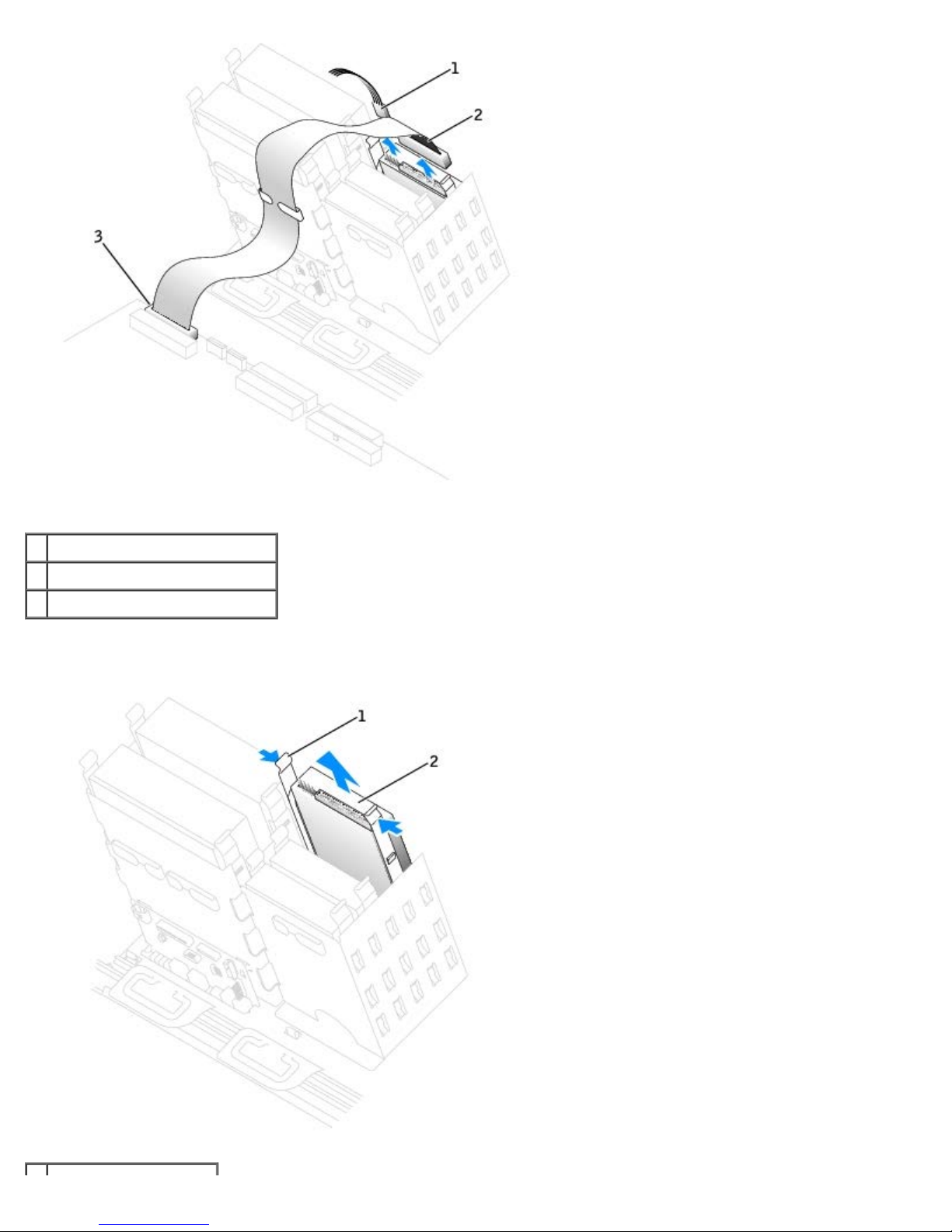
Removing and Replacing Parts: Dell Precision Workstation 470 and 670 Computers User's Guide
1 power cable
2 floppy-drive cable
3 floppy-drive connector (DSKT)
3. Press inward on the two tabs on the sides of the drive, slide the drive upward, and then remove it from the floppydrive bay.
file:///T|/htdocs/systems/ws670/EN/ug_en/before.htm[3/20/2013 9:31:52 AM]
Page 91
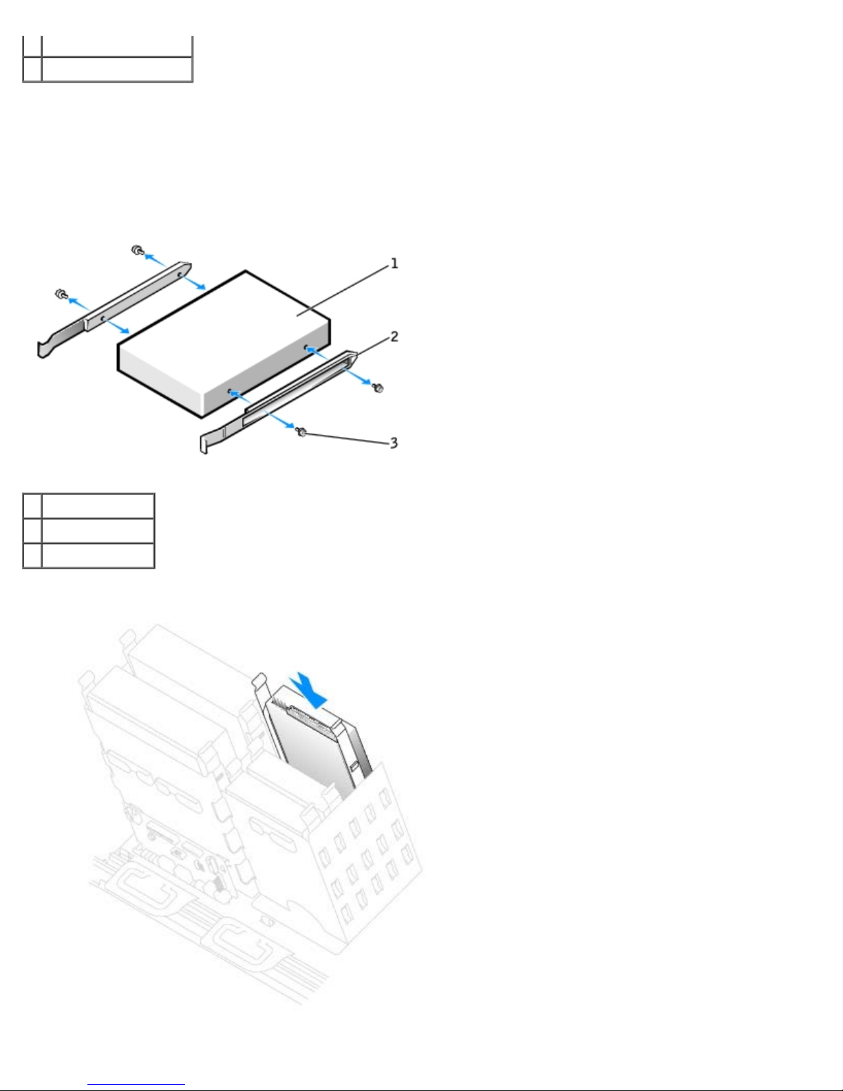
Removing and Replacing Parts: Dell Precision Workstation 470 and 670 Computers User's Guide
1 tabs (2)
2 floppy drive (optional)
Installing a Floppy Drive
1. If you are replacing a drive and the new drive does not have the bracket rails attached, remove the rails from the old
drive by removing the two screws that secure each rail to the drive. Attach the bracket to the new drive by aligning the
screw holes on the drive with the screw holes on the bracket rails and then inserting and tightening all four screws (two
screws on each rail).
1 drive
2 bracket rails (2)
3 screws (4)
2. Gently slide the drive into place until the tabs securely click into position.
file:///T|/htdocs/systems/ws670/EN/ug_en/before.htm[3/20/2013 9:31:52 AM]
Page 92
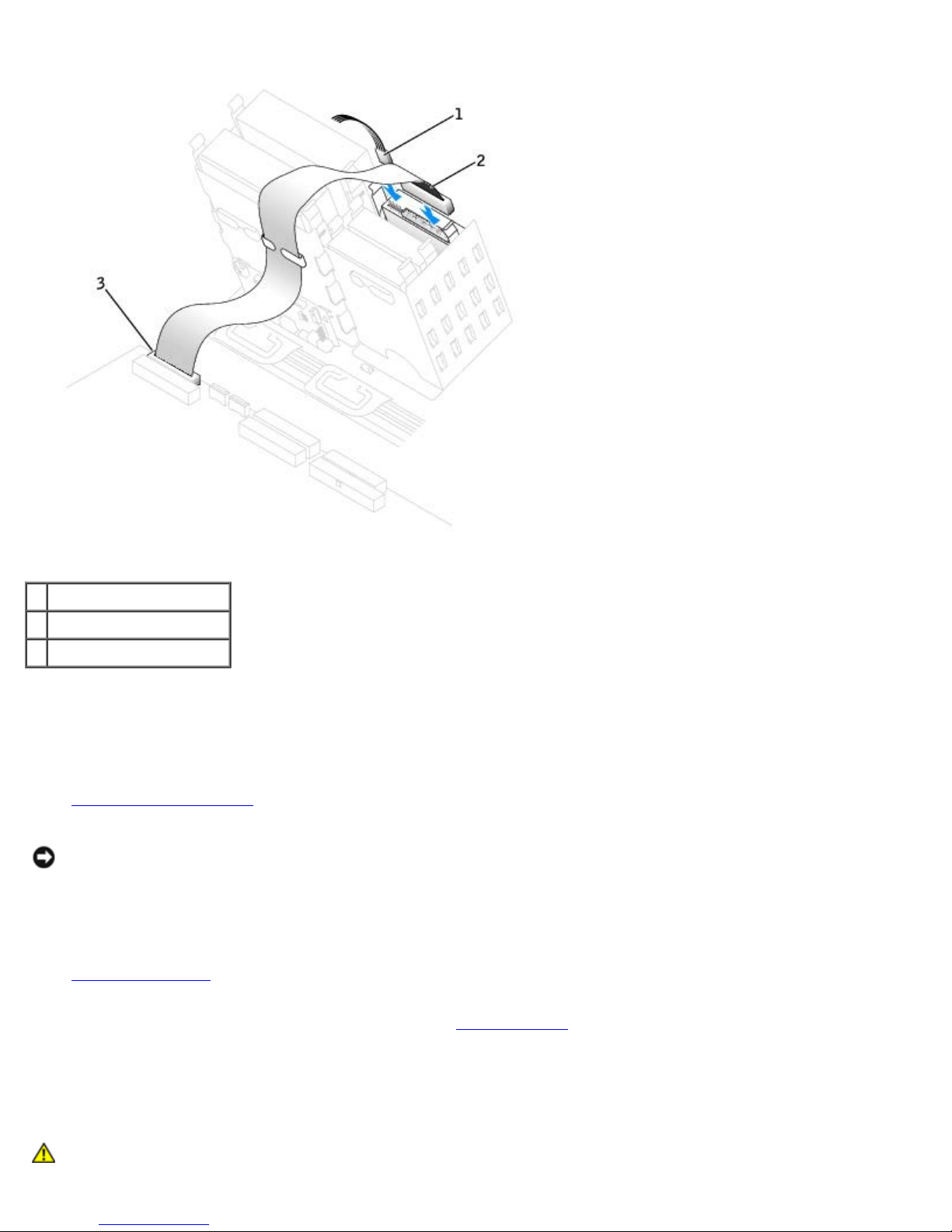
Removing and Replacing Parts: Dell Precision Workstation 470 and 670 Computers User's Guide
3. Attach the power and floppy-drive cables to the floppy drive.
the Product Information Guide.
1 power cable
2 floppy-drive cable
3 system board connector
4. If you are installing a new floppy drive rather than replacing a drive, remove the front-panel inserts.
From inside the drive bay, gently press on each side of the insert until it pops out.
5. Check all cable connections, and fold cables out of the way to provide airflow for the fan and cooling vents.
6. Close the computer cover.
NOTICE: To connect a network cable, first plug the cable into the network wall jack and then plug it into the computer.
7. Connect your computer and devices to electrical outlets, and turn them on.
See the documentation that came with the drive for instructions on installing any software required for drive operation.
8. Enter system setup
floppy drive.
9. To verify that your computer works correctly, run the Dell Diagnostics.
and update the appropriate Diskette Drive A option to reflect the size and capacity of your new
CD/DVD Drive
CAUTION: Before you begin any of the procedures in this section, follow the safety instructions located in
file:///T|/htdocs/systems/ws670/EN/ug_en/before.htm[3/20/2013 9:31:52 AM]
Page 93
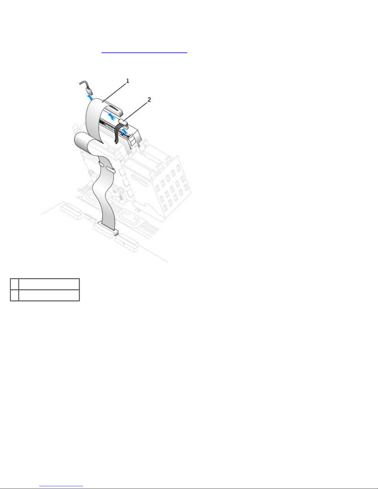
Removing and Replacing Parts: Dell Precision Workstation 470 and 670 Computers User's Guide
Removing a CD/DVD Drive
1. Follow the procedures in "Removing and Replacing Parts."
2. Disconnect the power and CD/DVD drive cables from the back of the drive.
1 CD/DVD drive cable
2 power cable
3. Press inward on the two tabs on the sides of the drive, and then slide the drive upward and remove it from the drive
bay.
file:///T|/htdocs/systems/ws670/EN/ug_en/before.htm[3/20/2013 9:31:52 AM]
Page 94
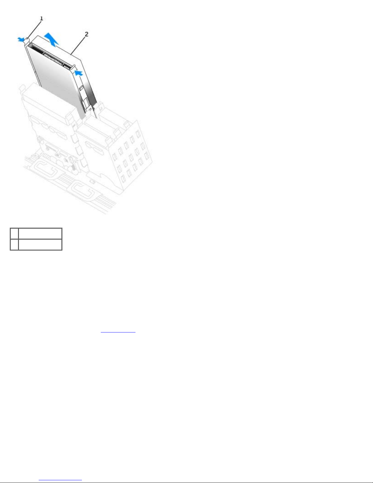
Removing and Replacing Parts: Dell Precision Workstation 470 and 670 Computers User's Guide
1 tabs (2)
2 CD/DVD drive
Installing a CD/DVD Drive
1. If you are installing a new drive, unpack the drive and prepare it for installation.
Check the documentation that accompanied the drive to verify that the drive is configured for your computer. If you are
installing an IDE drive, configure the drive for the cable select setting.
2. Connect the new drive to the set of rails that are attached to the inside of the computer cover. If a set of rails is not
attached inside the cover, contact Dell
3. If you are installing a replacement drive and the new drive does not have the bracket rails attached, remove the rails
from the old drive by removing the two screws that secure each rail to the drive. Attach the bracket to the new drive
by aligning the screw holes on the drive with the screw holes on the bracket rails and then inserting and tightening all
four screws (two screws on each rail).
for the number to call for assistance.
file:///T|/htdocs/systems/ws670/EN/ug_en/before.htm[3/20/2013 9:31:52 AM]
Page 95
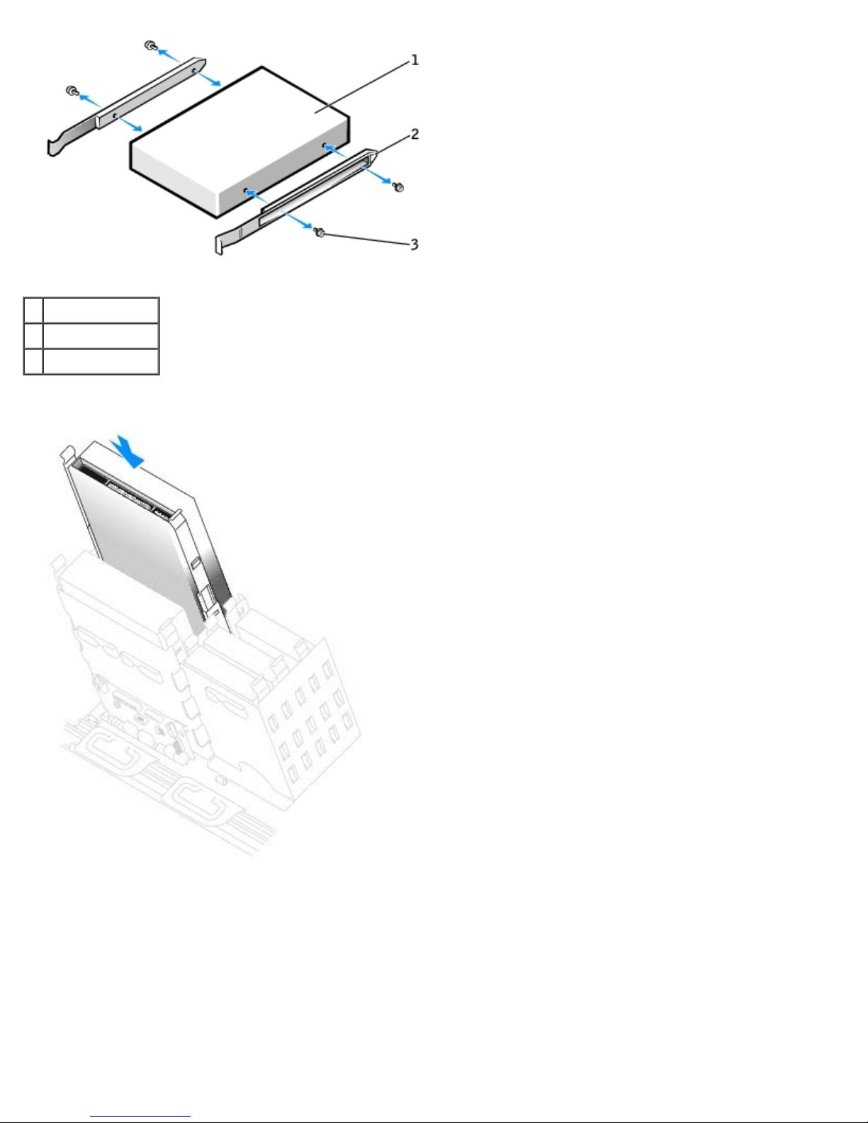
Removing and Replacing Parts: Dell Precision Workstation 470 and 670 Computers User's Guide
1 drive
2 bracket rails (2)
3 screws (4)
4. Gently slide the drive into place until the tabs securely click into position.
5. If you are installing a drive that has its own controller card, install the controller card in an expansion slot.
See the documentation that accompanied the drive and controller card to verify that the configuration is correct for
your computer.
6. Connect the power and CD/DVD drive cables to the drive.
If you are adding a drive that has an audio cable, connect the audio cable to the audio connector on the system board.
file:///T|/htdocs/systems/ws670/EN/ug_en/before.htm[3/20/2013 9:31:52 AM]
Page 96
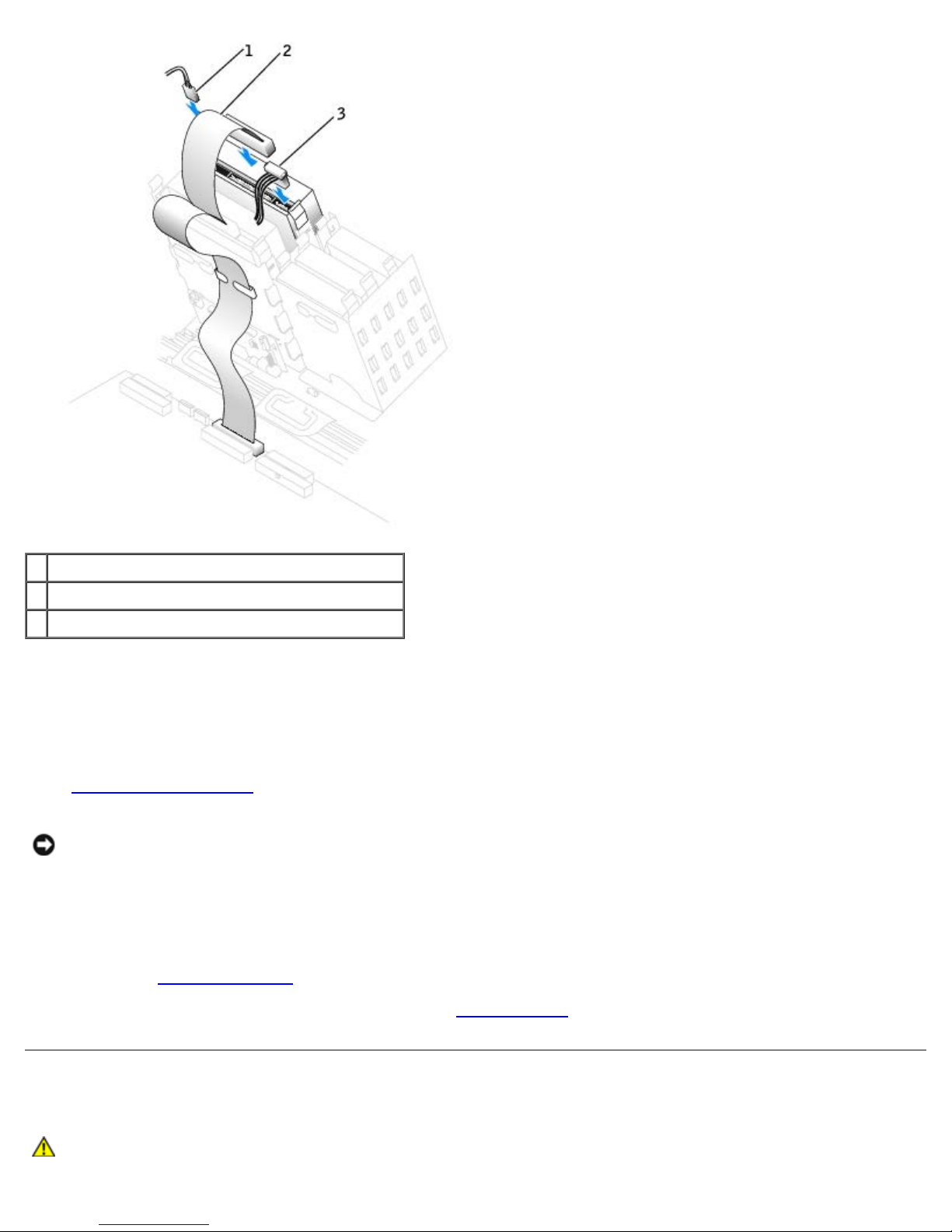
Removing and Replacing Parts: Dell Precision Workstation 470 and 670 Computers User's Guide
1 audio cable (some drives do not have this cable)
2 CD/DVD drive cable
3 power cable
7. If you are installing a new CD/DVD drive rather than replacing a drive, remove the
front-panel inserts.
From inside the drive bay, gently press on each side of the insert until it pops out.
8. Check all cable connections, and fold cables out of the way to provide airflow for the fan and cooling vents.
9. Close the computer cover
NOTICE: To connect a network cable, first plug the cable into the network wall jack and then plug it into the computer.
10. Connect your computer and devices to electrical outlets, and turn them on.
See the documentation that came with the drive for instructions on installing any software required for drive operation.
11. Update your configuration information by setting the appropriate Drive option (0 or 1) under Drives: Secondary to
Auto. See "Advanced Features
12. To verify that your computer works correctly, run the Dell Diagnostics
.
" for more information.
.
Cards
CAUTION: Before you begin any of the procedures in this section, follow the safety instructions located in
the Product Information Guide.
file:///T|/htdocs/systems/ws670/EN/ug_en/before.htm[3/20/2013 9:31:52 AM]
Page 97

Removing and Replacing Parts: Dell Precision Workstation 470 and 670 Computers User's Guide
NOTICE: To prevent static damage to components inside your computer, discharge static electricity from your body
before you touch any of your computer's electronic components. You can do so by touching an unpainted metal surface
on the computer chassis.
Your Dell™ Precision 670 computer provides the following slots for PCI and PCI Express cards:
One PCI card slot
Three PCIx slots
One PCI Express x16 card slot
One PCI Express x8 card slot (runs at x4 only)
Your Dell™ Precision 470 computer provides the following slots for PCI and PCI Express cards:
One PCI card slot
One PCIx slots
One PCI Express x16 card slot
One PCI Express x8 card slot (runs at x4 only)
PCI Cards
If you are installing or replacing a card, follow the procedures in the next section. If you are removing but not replacing a
card, see "Removing a PCI Card
If you are replacing a card, remove the current driver for the card from the operating system.
If you are installing or replacing a PCI Express card, see "Installing a PCI Express Card
Installing a PCI Card
13. Follow the procedures in "Removing and Replacing Parts."
14. Press the lever on the card retention arm and raise the retention arm.
."
."
file:///T|/htdocs/systems/ws670/EN/ug_en/before.htm[3/20/2013 9:31:52 AM]
Page 98
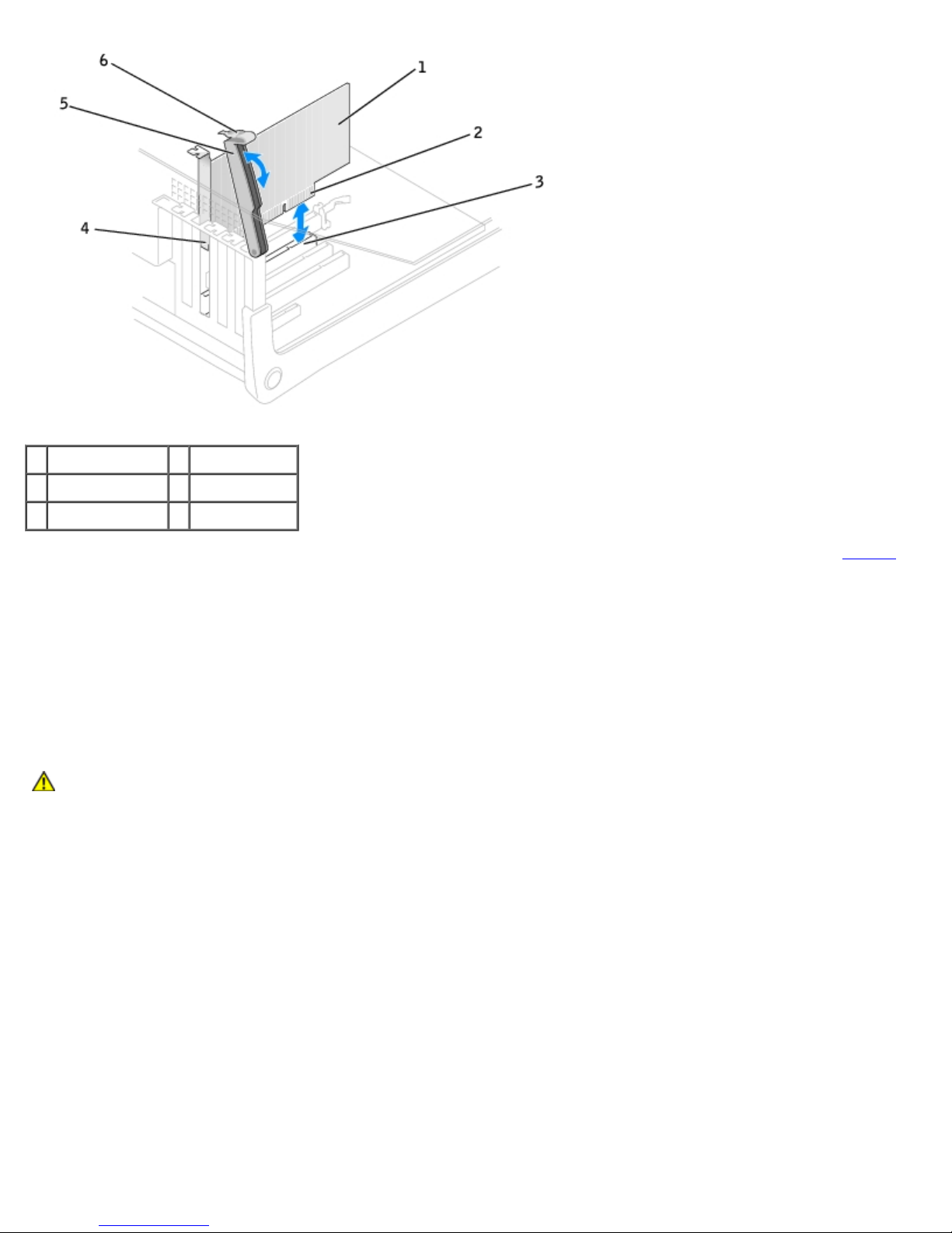
Removing and Replacing Parts: Dell Precision Workstation 470 and 670 Computers User's Guide
1 PCI card 4 filler bracket
2 edge connector 5 retention arm
3 card connector 6 lever
15. If you are installing a new card, remove the filler bracket to create a card-slot opening. Then continue with step 17
16. If you are replacing a card that is already installed in the computer, remove the card.
If necessary, disconnect any cables connected to the card. Grasp the card by its top corners, and ease it out of its
connector.
17. Prepare the card for installation.
See the documentation that came with the card for information on configuring the card, making internal connections, or
otherwise customizing it for your computer.
CAUTION: Some network adapters automatically start the computer when they are connected to a
network. To guard against electrical shock, be sure to unplug your computer from its electrical outlet
before installing any cards.
18. Place the card in the connector and press down firmly. Ensure that the card is fully seated in the slot.
If the card is full-length, insert the end of the card into the card guide bracket as you lower the card toward its
connector on the system board. Insert the card firmly into the card connector on the system board.
.
file:///T|/htdocs/systems/ws670/EN/ug_en/before.htm[3/20/2013 9:31:52 AM]
Page 99
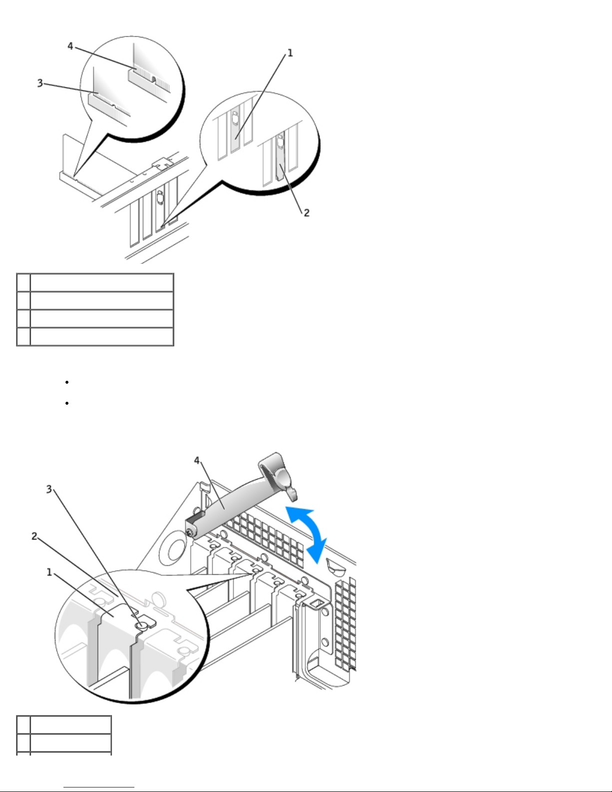
Removing and Replacing Parts: Dell Precision Workstation 470 and 670 Computers User's Guide
1 bracket within slot
2 bracket caught outside of slot
3 fully seated card
4 not fully seated card
19. Before you lower the retention arm, ensure that:
The tops of all cards and filler brackets are flush with the alignment bar.
The notch in the top of the card or filler bracket fits around the alignment guide.
20. Press the retention arm into place, securing the card(s) in the computer.
1 filler bracket
2 alignment bar
file:///T|/htdocs/systems/ws670/EN/ug_en/before.htm[3/20/2013 9:31:52 AM]
Page 100

Removing and Replacing Parts: Dell Precision Workstation 470 and 670 Computers User's Guide
3 alignment guide
4 retention arm
NOTICE: Do not route card cables over or behind the cards. Cables routed over the cards can prevent the computer
cover from closing properly or cause damage to the equipment.
21. Connect any cables that should be attached to the card.
See the documentation for the card for information about the card's cable connections.
NOTICE: To connect a network cable, first plug the cable into the network wall jack and then plug it into the computer.
22. Close the computer cover, reconnect the computer and devices to electrical outlets, and then turn them on.
23. If you installed a sound card:
a. Enter system setup
b. Connect external audio devices to the sound card's connectors. Do not connect external audio devices to the
microphone, speaker/headphone, or line-in connectors on the back panel.
24. If you installed an add-in network adapter:
a. Enter system setup
Off.
b. Connect the network cable to the add-in network adapter's connectors. Do not connect the network cable to the
integrated connector on the back panel.
25. Install any drivers required for the card as described in the card documentation.
, select Integrated Devices, and then change the setting for Sound to Off.
, select Integrated Devices, and then change the setting for Network Interface Card to
Removing a PCI Card
1. Follow the procedures in "Before You Begin."
2. Press the lever on the card retention arm and raise the retention arm.
3. If necessary, disconnect any cables connected to the card.
4. Grasp the card by its top corners, and ease it out of its connector.
5. If you are removing the card permanently, install a filler bracket in the empty card-slot opening.
If you need a filler bracket, contact Dell
NOTE: Installing filler brackets over empty card-slot openings is necessary to maintain FCC certification of the
computer. The brackets also keep dust and dirt out of your computer.
6. Lower the retention arm and press it into place, securing the card(s) in the computer.
NOTICE: To connect a network cable, first plug the cable into the network wall jack and then plug it into the computer.
7. Close the computer cover, reconnect the computer and devices to electrical outlets, and then turn them on.
8. Remove the card's driver from the operating system.
9. If you removed a sound card:
a. Enter system setup, select Integrated Devices, and then change the setting for Sound to On.
file:///T|/htdocs/systems/ws670/EN/ug_en/before.htm[3/20/2013 9:31:52 AM]
.
 Loading...