

Page 1
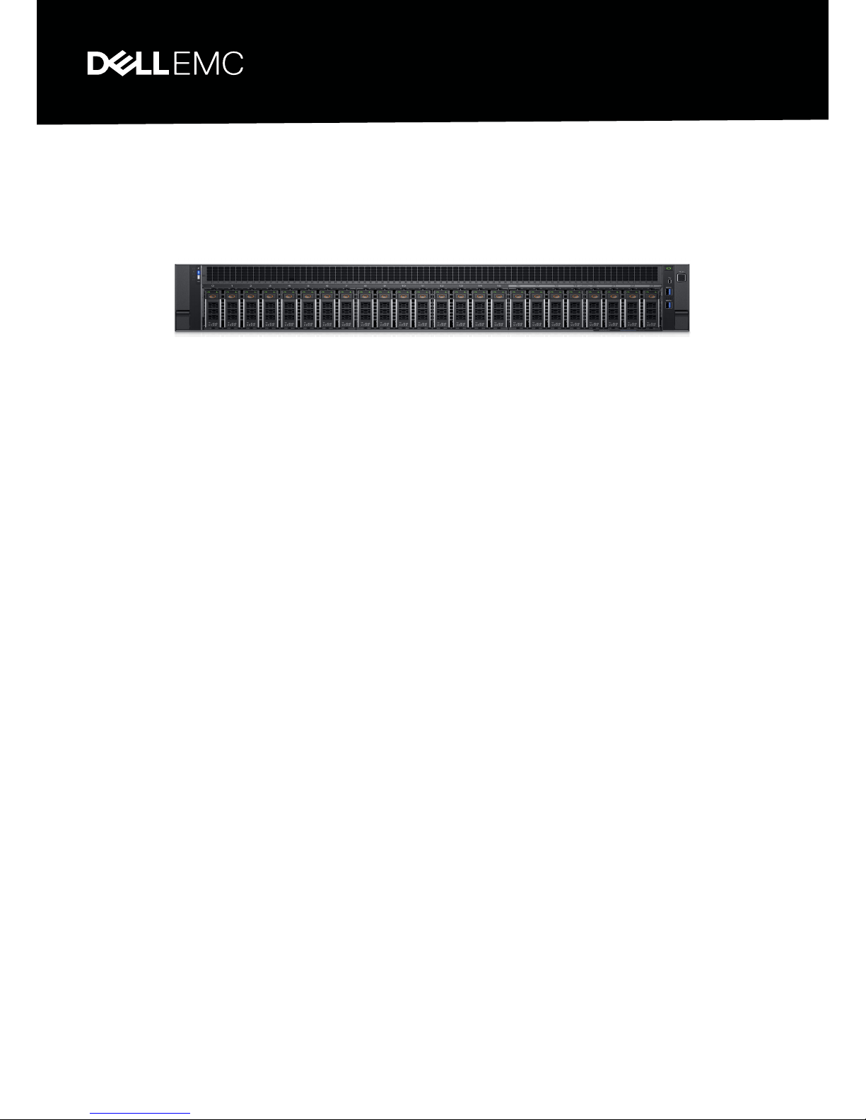
PowerEdge R940
Latest 4-socket, 3U monolithic rack server
designed for complex workloads using
highly scalable memory and network options.
The following documentation is designed as both an instructional aid and
online reference material for the Dell EMC PowerEdge R940 rack
server. The material introduces new technologies and features specic to
the PowerEdge R940 in an effort to better prepare technicians to provide
outstanding support to our customers.
TECHNICAL GUIDE
Page 2

Notes, cautions, and warnings
NOTE: A NOTE indicates important information that helps you make better use of your product.
CAUTION: A CAUTION indicates either potential damage to hardware or loss of data and tells you how to avoid the problem.
WARNING: A WARNING indicates a potential for property damage, personal injury, or death.
Copyright © 2017 Dell Inc. or its subsidiaries. All rights reserved. Dell, EMC, and other trademarks are trademarks of Dell Inc. or its subsidiaries. Other
trademarks may be trademarks of their respective owners.
2017 - 06
Rev. A00
Page 3

Contents
1 System overview ...........................................................................................................................................6
Introduction.........................................................................................................................................................................6
New Technologies..............................................................................................................................................................6
2 System features ............................................................................................................................................8
Specications..................................................................................................................................................................... 8
3 Chassis views and features ..........................................................................................................................10
Chassis view and features...............................................................................................................................................10
Front panel view and features...................................................................................................................................10
Back view features..................................................................................................................................................... 10
2.5-in x8 hard drive passive backplane.....................................................................................................................11
2.5-in x24 hard drive active backplane.................................................................................................................... 12
Control panels, LCD and LED..........................................................................................................................................12
Quick Resource Locator (QRL).......................................................................................................................................12
Security features...............................................................................................................................................................13
4 Processor .................................................................................................................................................... 14
Processor Features...........................................................................................................................................................14
Supported Processors......................................................................................................................................................14
Processor installation....................................................................................................................................................... 15
Chipset...............................................................................................................................................................................15
5 Supported Memory...................................................................................................................................... 17
Memory speed.................................................................................................................................................................. 17
Memory congurations and population rules................................................................................................................ 17
Memory RAS features......................................................................................................................................................18
6 Storage........................................................................................................................................................ 19
Supported hard drives......................................................................................................................................................19
RAID Controllers............................................................................................................................................................... 19
Internal persistent storage..............................................................................................................................................20
Lifecycle Controller 3.0..............................................................................................................................................20
IDSDM/vash module...............................................................................................................................................20
Boot Optimized Storage Subsystem (BOSS).........................................................................................................20
External storage................................................................................................................................................................21
Optical drives...............................................................................................................................................................21
Tape drives...................................................................................................................................................................21
7 Networking and PCIe...................................................................................................................................22
PCIe expansion.................................................................................................................................................................22
PCIe slots..........................................................................................................................................................................22
Contents
3
Page 4

PCIe expansion cards...................................................................................................................................................... 22
PCIe slot mapping......................................................................................................................................................22
8 Power, thermal, and acoustics .................................................................................................................... 24
Power, thermal and acoustics.........................................................................................................................................24
Power consumption and energy eciency.............................................................................................................24
Power supply units...........................................................................................................................................................25
Thermal and acoustics.................................................................................................................................................... 26
Thermal design.................................................................................................................................................................26
Acoustical design............................................................................................................................................................. 26
9 Rack Rails....................................................................................................................................................28
Cable Management Arm (CMA) and Strain Relief Bar (SRB)....................................................................................28
Rack Installation............................................................................................................................................................... 29
Installing 14G Systems in Sliding Rails........................................................................................................................... 30
10 Supported operating system....................................................................................................................... 31
Supported virtualization...................................................................................................................................................31
11 OpenManage systems management............................................................................................................32
iDRAC Lifecycle controller.............................................................................................................................................. 32
iDRAC features and comparison.............................................................................................................................. 32
Agent-free management.................................................................................................................................................37
Agent-based management..............................................................................................................................................37
OpenManage consoles.................................................................................................................................................... 37
OpenManage systems management tools, utilities and protocols.............................................................................38
Integration with third-party consoles............................................................................................................................ 38
OpenManage connections with third-party consoles.................................................................................................38
Server management operations.....................................................................................................................................39
12 Appendix A. Additional specications..........................................................................................................41
Chassis dimensions...........................................................................................................................................................41
Environmental specications...........................................................................................................................................41
Particulate and gaseous contamination specications .........................................................................................42
Standard operating temperature..............................................................................................................................43
Expanded operating temperature............................................................................................................................ 44
Video specications.........................................................................................................................................................44
USB peripherals................................................................................................................................................................45
13 Appendix B. Standards compliance.............................................................................................................46
14 Appendix C Additional resources.................................................................................................................47
15 Appendix D. Support and deployment services...........................................................................................48
Server Deployment Services..........................................................................................................................................48
Remote Consulting Services.......................................................................................................................................... 48
Data Migration Service....................................................................................................................................................48
4
Contents
Page 5

ProSupport Plus (for business-critical servers)...........................................................................................................49
ProSupport Enterprise Suite...........................................................................................................................................49
ProSupport....................................................................................................................................................................... 49
ProSupport Flex for Data Center...................................................................................................................................50
Additional professional services..................................................................................................................................... 50
Dell Education Services...................................................................................................................................................50
Dell Global Infrastructure Consulting Services.............................................................................................................50
Dell managed services......................................................................................................................................................51
Contents 5
Page 6

System overview
Introduction
The Dell EMC PowerEdge R940 is a latest 4-socket, 3U monolithic rack server designed to run complex workloads using highly scalable
memory, I/O, and network options. The system features the Intel Xeon Processor Scalable family, with up to 48 DDR4 DIMMs, up to 13 PCI
Express (PCIe) 3.0 enabled expansion slots, and a choice of embedded NIC technologies.
The PowerEdge R940 is a general-purpose platform capable of handling demanding workloads and applications, such as data warehouses,
ecommerce, databases, and high-performance computing (HPC).
The PowerEdge R940 adds extraordinary storage capacity options, making it well-suited for data-intensive applications that require greater
storage, while not sacricing I/O performance.
New Technologies
Table 1. New technologies
Technology Detailed Description
Intel Xeon Processor Scalable family Refer the Processor section for specic SKU details.
• 14nm process technology
• Intel Ultra Path Interconnect (UPI) up to 3 links @ 10.4GT/s with shelf-4
• Up to 28 cores per socket with Hyper-Threading (HT)
• 6x DDR4 channels @ 2666 MT/s 2 DPC. 3 DPC not supported.
• Max TDP: 165W (Note: Higher TDP skus up to 240W – UI)
• Mismatched SKUs not allowed
Intel C620 Chipset Intel Platform Controller Hub (PCH) with Intel Node Manager 4.0 ME
2666 MT/s DDR4 Memory Select SKUs of the Intel Xeon Skylake Scalable family processors support 2666 MT/s memory.
The R940 supports two DIMMs per channel max at 2666 MT/s with these processors. See the
Memory section for additional speed/population details.
• 6x DDR4 Channels per socket, 2 DIMMs per channel (2DPC)
• Up to 2666 MT/s max (CPU sku and DIMM-dependent)
• RDIMMs up to 32GB & LRDIMMs up to 64GB & 128GB supported
iDRAC9 with Lifecycle Controller The embedded systems management solution for PowerEdge features hardware and rmware
inventory and alerting, in- depth memory alerting, faster performance, a dedicated gigabit port
and many more features. See the OpenManage systems management section for details
Wireless Management The Quick Sync feature is an extension of NFC based low bandwidth Quick sync interface. Quick
Sync 2.0 will oer feature parity with NFC interface with improved user experience. Since the
introduction of iDRAC in PowerEdge Server, the server management has been improved by
adding dierent local and remote user interfaces (Web GUI, RACADM, WSMAN, BIOS F2 Setup,
and LCD) to iDRAC. The addition of Quick Sync 1.0 (NFC) interface in 13G server with handheld
devices (Mobile, tablet) and OMM Android application. To extend this Quick Sync feature to wide
1
6 System overview
Page 7

Technology Detailed Description
variety of Mobile OS’s with higher data throughput, the Quick Sync 2.0 version replaces NFC
technology.
System overview 7
Page 8

System features
Specications
Table 2. Technical specications
Feature Specication
Form factor 3U rack
Processors Intel Xeon Processor Scalable family
Processor sockets 2 socket or 4 sockets
Internal interconnect Intel Ultra Path Interconnect (UPI) up to 10.4 GT/s
Chipset Intel C620
Memory
• Up to 6 TB-48 DIMM slots
• RDIMM-up to 32 GB
• LRDIMM-up to 64 GB and 128 GB
PCIe slots Maximum 13 PCIe slots (three x8 slots and ten x16 slots)
RAID controller
• H330+
• H740P
• H840
• 12 Gb SAS HBA
• Software RAID: S140
• Hardware RAID: M.2 SATA adapter (BOSS)
Drives
• 2.5-in, 12 GB SAS and 6 GB SATA
• 8 hard drives on passive backplane
• 24 hard drives on active backplane with up to 12 PCIe NVMe hard drive capable universal slots.
Maximum internal
storage
• Up to 122 TBs using 12x2.5-in 3.84 TB SAS/SATA/SSD/NVMe + 12x2.5-in 6.4 TB NVMe PCIe SSD's.
Embedded NIC
• Flexible Rack Network Daughter Cards (rNDC).
• PCIe Gen 3 x8
Power supply
• Platinum AC supported power supplies: 1100 W, 1600 W, and 2000 W, 2400 W
• DC supported power supply: 1100 W
Availability
• RDIMM, LRDIMM
• Hot-plug hard drives, redundant cooling fans, and power supply
• Internal Dual SD Module (IDSDM)
• Boot Optimized Storage Subsystem (BOSS) via M.2
2
8 System features
Page 9

Feature Specication
Systems management
• LC 3.x
• OpenManage
• QuickSync2.0
• OMPC3
• Digital License Key
• iDRACDirect (dedicated micro-USB port)
• Easy Restore
• vFlash
Operating systems
• RedHat Enterprise Linux 6.9 Server x86_64
• RedHat Enterprise Linux 7.3 Server x86_64
• Novell SuSE Linux Enterprise Server 11 (with PLDP) SP4x86_64
• Novell SuSE Linux Enterprise Server 12 SP2 x86_64
• MS, Windows Server 2016
• MS, Windows Server 2012 R2
For more information on the specic versions and additions, visit Dell.com/OSsupport.
System features 9
Page 10
Chassis views and features
Chassis view and features
Front panel view and features
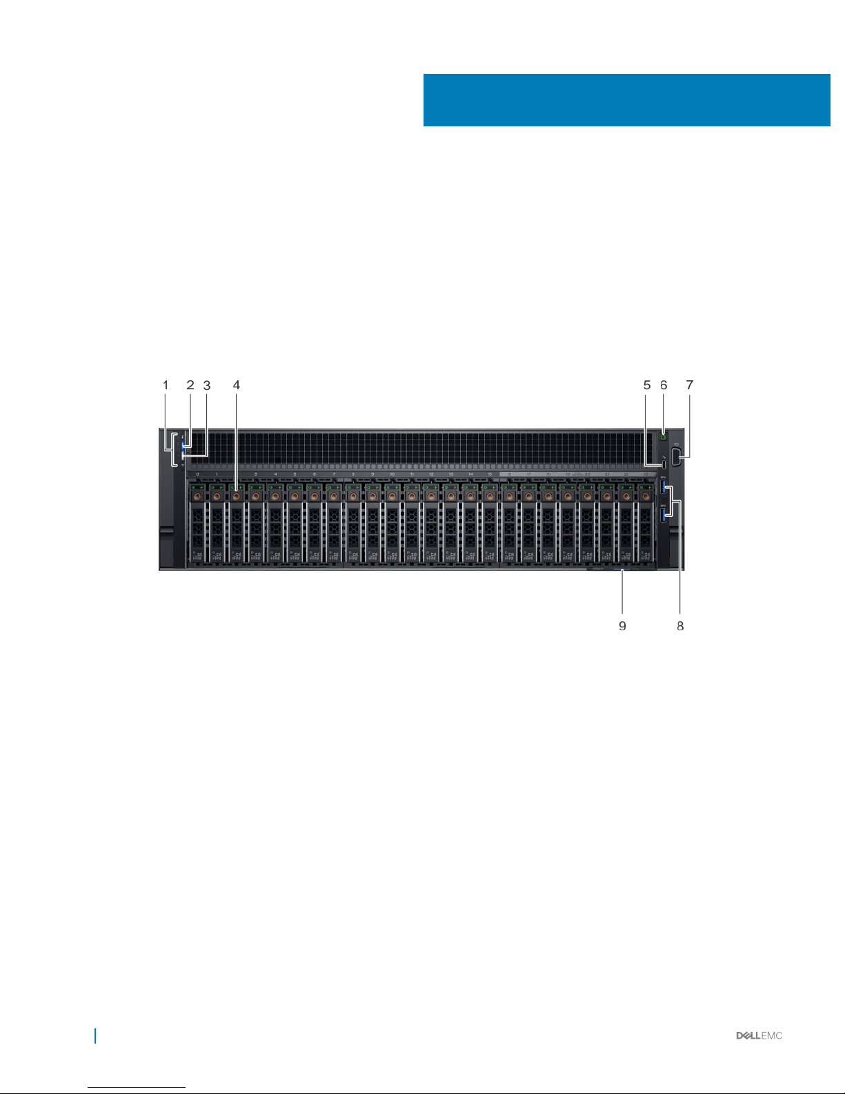
The following components are located on the front of the PowerEdge R940:
Figure 1. PowerEdge R940 front panel
1 Left control panel
2 System health and system identier
3 iDRAC Quick Sync 2 wireless indicator
4 Hard drives
5 USB management port
6 Power button
7 Video connector
8 USB management port/iDRAC Direct
9 Information tag
For more information on the HDD numbering, see the Dell PowerEdge R940 Hardware Owner's Manual on www.dell.com/support
Back view features
The following components are located on the back of the PowerEdge R940:
3
10 Chassis views and features
Page 11
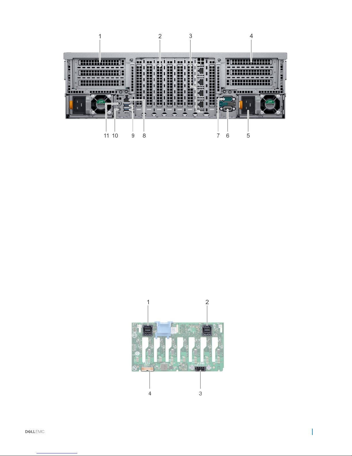
Figure 2. PowerEdge R940 back view
1 Half-height PCIe expansion card slot
2 Full-height PCIe expansion slots
3 Ethernet connector (4)
4 Half-height PCIe expansion card slot
5 Power supply unit (2)
6 Video port
7 Serial port
8 iDRAC9 Enterprise port
9 USB port
10 System identication button
11 Status indicator cable port
2.5-in x8 hard drive passive backplane
This passive backplane allows 8x2.5-in SAS/SATA hard drives to be connected to the backplane. As a passive backplane, it does not
support the exible assignment of hard drives to nodes. Each node in the chassis gets equal number of total available hard drives.
Figure 3. Hard drive backplane 2.5-in x8
Chassis views and features
11
Page 12
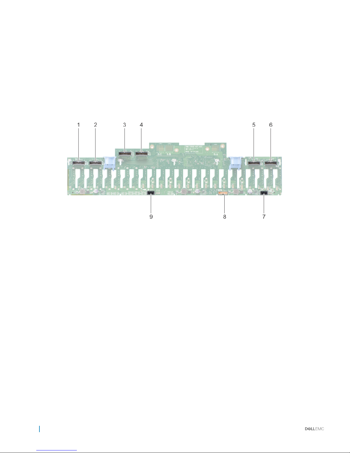
1 SAS connector (J_SAS_B)
2 SAS connector (J_SAS_A)
3 Power connector (J_BP_PWR)
4 Signal connector (J_BP_SIG)
2.5-in x24 hard drive active backplane
The active backplane is capable of supporting 24x2.5-in SAS/SATA hard drives and 12x NVMe hard drives. A SAS Expander Daughter Card
is necessary to achieve higher volume hard drive conguration and it is integrated with the backplane via Xcede hard drive and power
connectors.
Figure 4. Hard drive backplane 2.5-in x24
1 PCIe connector (J_PCIE_B2)
2 PCIe connector (J_PCIE_A2)
3 PCIe connector (J_PCIE_B1)
4 PCIe connector (J_PCIE_A1)
5 PCIe connector (J_PCIE_B0)
6 PCIe connector (J_PCIE_A0)
7 PCIe connector (J_BP_PWR_A)
8 Signal connector (J_BP_SIG)
9 PCIe connector (J_BP_PWR_B)
Control panels, LCD and LED
For more information about the PowerEdge R940 control panels, see the PowerEdge R940's Owner’s Manual at Dell.com/Support/
Manuals.
Quick Resource Locator (QRL)
The Embedded Service Tag (EST) this generation will contain the Service Tag number and the iDRAC password. Embedding the Service
Tag and iDRAC password in the QRL allows the mobile application to display information on their conguration, warranty status, specic
iDRAC password and service level agreement. Additionally, the EST will allow us to understand how our customers are using QRL.
The following image shows the service tag QRL label:
12
Chassis views and features
Page 13
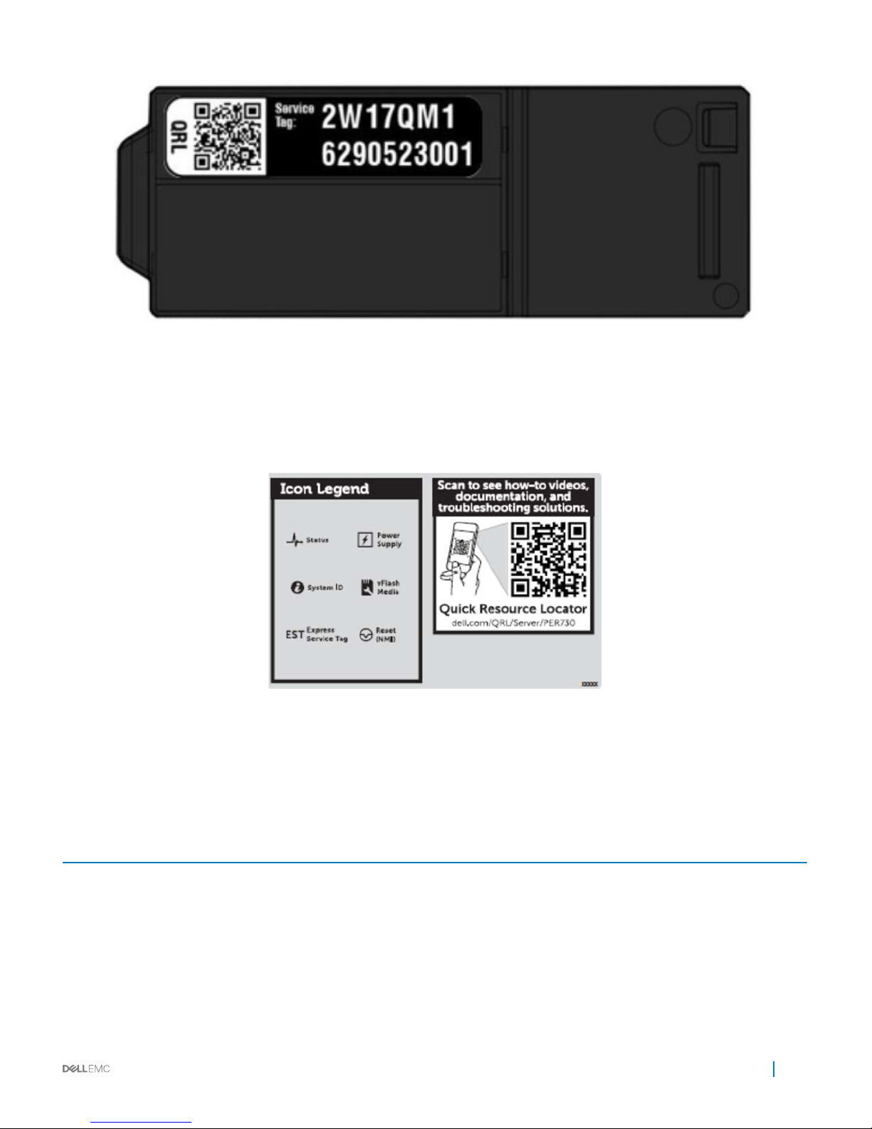
Figure 5. Service tag QRL label
The QRL EST label has a service tag embedded into the QR code that the QRL website uses to look up system info in the service tag data
base. From that database the QRL website pulls warranty info and factory conguration details. After viewing this, the customer can move
on to the product page.
The following image shows the chassis QRL label:
Figure 6. Chassis QRL label
Security features
The latest generation of PowerEdge servers has the features listed in the table to help ensure the security of your data center.
Table 3.
Security features
Security feature Description
Cover latch A tooled latch is integrated in the top cover to secure it to the rack
chassis.
TPM The Trusted Platform Module (TPM) is used to generate/store
keys, protect/authenticate passwords, and create/store digital
certicates. TPM 1.2 is supported.
Power-o security BIOS has the ability to disable the power button function.
Chassis views and features 13
Page 14

Processor
Processor Features
The Intel Xeon Skylake Scalable family is the next generation core architecture with improved Instructions per Cycle (IPC) and other
architectural improvements. The Intel Xeon Skylake Scalable family features are as follows:
• Virtual address space of 48 bits and a physical address space of 46 bits.
• Intel Hyper-Threading Technology (Intel® HT Technology) when enabled allow each core to support two threads.
• First Level Cache (FLC) 64 KB total. The FLC is comprised of a 32 KB ICU (Instruction Cache) and 32 KB DCU (Data Cache).
• MB Mid-Level Cache (MLC) per core (non-inclusive with the LLC).
• Intel® Advanced Vector Extensions 512 (Intel® AVX-512) with a single AVX512 fused multiply add (FMA) execution units. SKUs which
support Advanced RAS enable a 2nd FMA execution unit.
Supported Processors
Table 4. Supported processor levels and features
Processor levels Features
81xx-Platinum
• 2S-2UPI, 2S-3UPI, 4S-2UPI, 4S-3UPI, and 8S-3UPI capability
• 6-ch DDR4 @ 2666
• 3 UPI links @ 10.4GT/s
• Intel® Turbo Boost
• Intel® Hyper-Threading
• Intel® AVX-512 (2 512-bit FMAs)
• 48 lanes PCIeGen3
• Node Controller Support
• Advanced RAS
61xx-Gold
• 2S-2UPI, 2S-3UPI, 4S-2UPI, and 4S-3UPI capability
• 6-ch DDR4 @ 2666
• 3 UPI links @ 10.4GT/s
• Intel® Turbo Boost
• Intel® Hyper-Threading
• Intel® AVX-512 (2 512-bit FMAs)
• 48 lanes PCIeGen3
• Node Controller Support
• Advanced RAS
51xx-Gold
• 2S-2UPI & 4S-2UPI capability
• 6-ch DDR4 @ 2400
• 2 UPI links @ 10.4GT/s
• Intel® Turbo Boost
• Intel® Hyper-Threading
4
14 Processor
Page 15

Processor levels Features
• Intel® AVX-512 (11512-bit FMA)
• 48 lanes PCIeGen3
• Advanced RAS
Table 5. Feature comparison table
Feature 81xx-Platinum 61xx-Gold 51xx-Gold
Number of UPI links 3 3 2
UPI speed 10.4 GT/s 10.4 GT/s 10.4 GT/s
Supported topologies 3 UPI: 2S-2UPI,2S-3UPI,
4S-2UPI, 4S-3UPI, 8S-3UPI
3 UPI: 2S-2UPI,2S-3UPI,
4S-2UPI, 4S-3UPI
2S-2UPI,4S-2UPI
Node Controller Support Yes Yes No
Number of memory
channels
6 6 6
DDR4 speed 2666 2666 2400
Memory capacity 768 GB, 1.5 TB-SKUs: 8180,
8176, 8170, and 8160
768 GB, 1.5 TB-SKUs: 6140,
6134, and 6142
768 GB
Processor installation
For processor installation instructions, see the Dell PowerEdge R940 Hardware Owner's Manual
Chipset
The Intel C620 PCH provides extensive I/O support. Functions and capabilities include:
• ACPI Power Management Logic Support, Revision 4.0a
• PCI Express* Base Specication Revision 3.0
• Integrated Serial ATA host controller, supports data transfer rates of up to 6 Gb/s on all ports.
• xHCI USB controller with SuperSpeed USB 3.0 ports
• Direct Media Interface
• Enhanced Serial Peripheral Interface
• Flexible I/O—Allows some high speed I/O signals to be congured as PCIe* root ports, PCIe* uplink for use with certain PCH SKUs,
SATA (and sSATA), or USB 3.0.
• General Purpose Input Output (GPIO)
• Low Pin Count interface, interrupt controller, and timer functions
• System Management Bus Specication, Version 2.0
• Integrated Clock Controller / Real Time Clock Controller
• Intel® High Denition Audio and Intel® Smart Sound Technology
• Integrated 10/1 Gb Ethernet
• Integrated 10/100/1000 Mbps Ethernet MAC
• Supports Intel Rapid Storage Technology Enterprise
• Supports Intel Active Management Technology and Server Platform Services
• Supports Intel Virtualization Technology for Directed I/O
• Supports Intel Trusted Execution Technology
Processor
15
Page 16

• JTAG Boundary Scan support
• Intel QuickAssist Technology
• Intel Trace Hub for debug
16 Processor
Page 17

Supported Memory
The PowerEdge R940 supports up to 48 DIMM slots, with up to 6 TB of memory and speeds up to 2666 MT/s. Supported DIMMs are
registered (RDIMMs) and load reduced (LRDIMMs) DIMMs which uses a buer to reduce memory loading and provide greater density
allowing maximum memory capacity.
Memory speed
The PowerEdge R940 supports memory speeds of 2666 MT/s, 2400 MT/s, and 1866 MT/s depending on the DIMM types installed and
congured. All memory on all of the processors and channels run at the same speed and voltage. The operating speed of the memory is
determined by the maximum speed supported by the processor, the speed settings in BIOS, and the operating voltage of the system.
Table 6. Memory conguration based on quantity and quality of DIMM
DIMM type DIMM ranking Capacity DIMM rated voltage
and speed
Max speed (MT/s) on 1
DPC
Max speed (MT/s) on
2 DPC
RDIMM 1R/2R 8 GB, 16 GB, 32 GB DDR4 (1.2 V), 2666
MT/s
2666 2666
LRDIMM 4R/8R 64 GB, 128 GB DDR4 (1.2 V), 2666
MT/s
2666 2666
Memory congurations and population rules
The R940 supports exible memory congurations ranging from 8 GB (minimum) to 128 GB (maximum). The R940 supports up to 12
DIMMs per processor or 24 DIMMs in a dual-processor and 48 DIMMs in a quad-processor conguration. Each R940 has 6 memory
channels per processor, with each channel supporting up to 2 DIMMs.
The R940 server support exible memory conguration according to the following population rules:
• If DIMMs of dierent speeds are mixed, all channels across all processors operate at the slowest DIMM's common frequency.
• DIMM type:
• All DIMMs must be DDR4 RDIMM and LRDIMM
• Only one type of DIMM is allowed per system-RDIMM, or LRDIMM. They cannot be mixed.
• DIMMs with dierent data width (x4 and x8 data width) can be mixed.
• The largest DIMM capacity is placed rst (slot A1 rst, then A2 and so on). The second CPU mirrors the rst CPU population rule.
• Maximum of two dierent capacity DIMMs are allowed in the system.
• Maximum of two dierent rank DIMMs are allowed in the system.
Table 7. DIMM mixing support
DIMM types RDIMM LRDIMM 3DS LRDIMM
RDIMM allowed not allowed not allowed
LRDIMM not allowed allowed not allowed
3DS LRDIMM not allowed not allowed allowed
5
Supported Memory 17
Page 18

Memory RAS features
Reliability, Availability, and Serviceability (RAS) features help keep the system online and operational without signicant impact to
performance, and decreases data loss and crashing issues. RAS helps in rapid and accurate diagnosis of system faults.
Table 8. Supported RAS features
Feature Description
Dense conguration optimized prole Increased memory reliability can be a result from this selectable
platform prole that adjusts parameters to reduce faults regarding
refresh rates, speed, temperature and voltage.
Memory demand and patrol scrubbing Demand scrubbing is the ability to write corrected data back to the
memory once a correctable error is detected on a read transaction.
Patrol scrubbing proactively searches the system memory, repairing
correctable errors.
Recovery from single DRAM device failure (SDDC) Recovery from Single DRAM Device Failure (SDDC) provides error
checking and correction that protects against any single memory
chip failure as well as multi- bit errors from any portion of a single
memory chip.
Failed DIMM isolation This feature provides the ability to identify a specic failing DIMM
channel pair, thereby enabling the user to replace only the failed
DIMM pair.
Memory mirroring Memory mirroring is a method of keeping a duplicate (secondary or
mirrored) copy of the contents of memory as a redundant backup
for use if the primary intra-socket memory fails. The mirrored copy
of the memory is stored in memory of the same processor socket.
Memory address parity protection This feature provides the ability to detect transient errors on the
address lines of the DDR channel.
Memory sparing (rank) Memory sparing allocates one rank per channel as a spare. If
excessive correctable errors occur in a rank or channel, they are
moved to the spare area while the operating system is running to
prevent the errors from causing an uncorrectable failure.
Memory thermal throttling This feature helps to optimize power/performance and can also be
used to prevent DIMMs from overheating.
18
Supported Memory
Page 19

Storage
The PowerEdge R940 provides storage expandability that allows you to adapt to your workload and operational demands. With
comprehensive storage options, the R940 oer various drive types, internal and external storage controllers, and dierent backplanes for
varied number of drives.
Topics:
• Supported hard drives
• RAID Controllers
• Internal persistent storage
• External storage
Supported hard drives
Table 9. Supported hard drives
Form factor Type Speed Rotational speed Capacities
2.5-inch
• SATA
• SSD
6 GB N/A 400GB, 480GB, 800GB,
960GB, 1200GB, 1600GB,
1920GB, 3200GB, 3840GB,
7680GB, 960GB(SED FIPS),
1920GB(SED FIPS)
2.5-inch
• SATA
6 GB 7.2 K 1TB, 2TB
2.5-inch
• SAS
12 GB 7.2 K 1TB, 2TB, 2TB(SED FIPS)
2.5-inch
• SAS
• SSD
12 GB N/A 400GB, 480GB, 800GB,
960GB, 1600GB, 1920GB,
3200GB, 3840GB, 7680GB,
15360GB, 1600GB(SED
FIPS), 1920GB(SED FIPS),
3200GB(SED FIPS),
3840GB(SED FIPS)
2.5-inch
• SAS
12 GB 10 K 600GB, 1.2TB, 1.8TB, 2.4TB,
1.2TB(SED FIPS), 2.4TB
(SED FIPS)
2.5-inch
• SAS
12 GB 15 K 300GB, 600GB, 900GB,
900GB (SED FIPS)
RAID Controllers
The PowerEdge R940 supports full height PERC adapter form factor only in slot 1 (for primary) and slot 6 (for secondary), and does not
support mini PERC form factors. The PERC controller oerings for R940 will be a heavy leverage of the 13G PERC family. New to the
6
Storage 19
Page 20

R940 PERC controller is the Harpoon-based Premium Performance tier oering. This high-end oering will drive IOPs performance and
enhanced SSD performance.
Table 10. PERC series oerings
Performance level Controller and description
Entry S140 (NVMe, M.2 SATA)
SW RAID SATA
Value H330+, 12Gb SAS HBA (External) Fury IOC
Memory: None
x8 12 Gb SAS
x8 PCIe 3.0
Premium performance H740P, H840 Harpoon 8x8 ROC
Memory: 4/8GB, NV 72-bit
Internal persistent storage
The PowerEdge R940 oers two internal persistent storage:
• Lifecycle Controller 3.0
• IDSDM/vash module
• Boot Optimized Storage Subsystem (BOSS)
Lifecycle Controller 3.0
For more information on Lifecycle Controller 3.0, visit Dell Lifecycle Controller integration for conguration manager.
IDSDM/vash module
This module contains the Internal Dual SD Module (IDSDM) and vash card that are combined into a single card module. There are two
SKUs available:
• vash
• vash + IDSDM
The IDSDM with vash module has a dedicated slot at the back of the system chassis. This is a Dell-proprietary PCIe x1 slot that uses a
USB 3.0 interface to host. In the system, the IDSDM and vash card size changes from SD to microSD and the supported capacity for
IDSDM microSD cards are 16 GB, 32 GB, or 64 GB, while for vash the capacity is 16 GB only. The write-protect switch is built onboard the
IDSDM/vash module.
Boot Optimized Storage Subsystem (BOSS)
BOSS is oered as a means of booting 14G servers to a full OS in the following scenarios:
• A solution such as IDSDM may be desired, but the target OS is a full OS (not just hypervisor).
20
Storage
Page 21

• The user does not to trade o the standard hot-plug hard drive slot for OS install.
BOSS is a PCIe card in the front to support up to two 80mm or 110mm M.2 SATA or PCIe x1 devices.
NOTE: The portfolio solution using a PCIe carrier card is not supported on R940.
NOTE: BOSS drives and daughter card are not hot-plug capable.
External storage
Table 11. Supported external storage devices
Device type Description
External Tape Supports connection to external USB tape products
NAS/IDM appliance software Supports NAS software stack
JBOD Supports connection to 12Gb MD-series JBODs
Optical drives
The R940 does not support internal optical drives. However, external USB optical drives will be supported.
Tape drives
The R940 does not support internal tape drives. However, external tape backup devices will be supported. Below is a list of supported
external tape drives:
• External RD1000 USB
• External LTO-5, LTO-6, and LTO-7 6 Gb SAS tape drives
• 114X rack mount chassis with LTO-5, LTO-6, and LTO-7 6 Gb SAS tape drives
• TL1000 with LTO-5, LTO-6, and LTO-7 6 Gb SAS tape drives
• TL2000 with LTO-5, LTO-6, and LTO-7 6 Gb SAS and 8Gb FC tape drives
• TL4000 with LTO-5, LTO-6, and LTO-7 6 Gb SAS and 8Gb FC tape drives
• ML6000 with LTO-5, LTO-6, and LTO-7 6 Gb SAS and 8Gb FC tape drives
Storage
21
Page 22

Networking and PCIe
The PowerEdge R940 oer balanced, scalable I/O capabilities including integrated PCIe 3.0 expansion slots. Dell network adapters and
daughtercards let you choose the right network fabric without using up valuable PCI slots. Pick the speed, technology, vendor and other
options such as switching independent partitioning lets you share and manage bandwidth on 10 Gbe connections.
PCIe expansion
For information on card installation, requirements, and slot priorities, see the PowerEdge R940 Owner's Manual on Dell.com/Support/
Manuals.
PCIe slots
Systems with 2 socket processors (without Processor Expansion Module) supports up to 7 PCIe Gen3 expansion slots. Systems with 4
socket processors (with Processor Expansion Module) supports up to 13 PCIe Gen3 expansion slots.
PCIe expansion cards
PCIe slot mapping
Table 12. PCIe slot mapping
Physical location Slot
number
Form factor Controlling
CPU
Slot electrical bandwidth/
Physical connector
Power Length
Baseboard 1 Full height CPU1 PCIe GEN3 x8 (x16 connector) 25 W half length
Baseboard 2 Full height CPU1 PCIe GEN3 x16 (x16 connector) 75 W half length
Baseboard 3 Full height CPU1 PCIe GEN3 x16 (x16 connector) 75 W half length
Baseboard 4 Full height CPU2 PCIe GEN3 x16 (x16 connector) 75 W half length
Baseboard 5 Full height CPU2 PCIe GEN3 x8 (x16 connector) 25 W half length
Baseboard 6 Full height CPU2 PCIe GEN3 x8 (x16 connector) 25 W half length
Baseboard 7 Full height CPU2 PCIe GEN3 x16 (x16 connector) 75 W half length
Riser 1 on PEM for 4
socket conguration
8 Full height CPU3 PCIe GEN3 x16 (x16 connector) 75 W 10.5" (~3/4 length)
Riser 1 on PEM for 4
socket conguration
9 Full height CPU3 PCIe GEN3 x16 (x16 connector) 25 W half length
Riser 1 on PEM for 4
socket conguration
10 Full height CPU3 PCIe GEN3 x16 (x16 connector) 25 W half length
7
22 Networking and PCIe
Page 23

Physical location Slot
number
Form factor Controlling
CPU
Slot electrical bandwidth/
Physical connector
Power Length
Riser 2 on PEM for
4 socket
conguration
11 Full height CPU4 PCIe GEN3 x16 (x16 connector) 75 W 10.5" (~3/4 length)
Riser 2 on PEM for
4 socket
conguration
12 Full height CPU4 PCIe GEN3 x16 (x16 connector) 25 W half length
Riser 2 on PEM for
4 socket
conguration
13 Full height CPU4 PCIe GEN3 x16 (x16 connector) 25 W half length
Networking and PCIe 23
Page 24

Power, thermal, and acoustics
Power, thermal and acoustics
PowerEdge servers have an extensive collection of sensors that automatically track thermal activity, which helps regulate temperature
thereby reducing server noise and power consumption.
Power consumption and energy eciency
Table 13. Power tools and technologies
Feature Description
Power supply units (PSU) portfolio Dell’s PSU portfolio includes intelligent features such as dynamically
optimizing eciency while maintaining availability and redundancy.
Find additional information in the Power supply units section.
Tools for right-sizing Energy Smart Solution Advisor (ESSA) is a tool that can help you
determine the most ecient conguration possible. With Dell’s
ESSA, you can calculate the power consumption of your hardware,
power infrastructure, and storage.
ESSA can help you determine exactly how much power your server
will use at a given workload, and the PSU Advisor can help you
choose the best, most ecient PSU for your workload.
Learn more at Dell.com/calc.
Energy Smart Data Center Assessment is a Dell Services oering
that uses infrastructure and thermal analysis to help maximize
system eciency. Learn more at Dell.com/EnergySmart.
Industry compliance Dell’s servers are compliant with all relevant industry certications
and guidelines, including 80 PLUS, Climate Savers, and ENERGY
STAR.
Power monitoring accuracy PSU power monitoring improvements include:
• Dell’s power monitoring accuracy is currently 1%, whereas the
industry standard is 5%
• More accurate reporting of power
• Better performance under a power cap
Power capping Use Dell’s systems management to set the power cap limit for your
systems to limit the output of a PSU and reduce system power
consumption. Dell is the rst hardware vendor to leverage Intel
Node Manager for circuit- breaker fast capping.
8
24 Power, thermal, and acoustics
Page 25

Feature Description
Systems management iDRAC9 Enterprise provides server- level management that
monitors, reports, and controls power consumption at the
processor, memory, and system level.
Dell OpenManage Power Center delivers group power management
at the rack, row, and data center level for servers, power
distribution units, and uninterruptible power supplies.
Active power management Intel Node Manager is an embedded technology that provides
individual server-level power reporting and power limiting
functionality. Dell oers a complete power management solution
comprised of Intel Node Manager accessed through Dell iDRAC9
Enterprise and OpenManage Power Center that allows policybased management of power and thermal at the individual server,
rack, and data center level.
Hot spare reduces power consumption of redundant power
supplies.
Thermal control of fan speed optimizes the thermal settings for
your environment to reduce fan consumption and lower system
power consumption.
Idle power enables Dell servers to run as eciently when idle as
when at full workload.
Fresh Air cooling FAC is supported with certain conguration limitations. With the
thermal design and reliability of Dell products, you can have the
capability to operate at excursion- based temperatures beyond the
industry standard of 35°C (95°F) without impacting your
availability model. This solution takes into account servers,
networking, storage, and other infrastructure.
Rack infrastructure Dell oers some of the industry’s highest- eciency power
infrastructure solutions, including:
• Power Distribution Units (PDUs)
• Uninterruptible Power Supplies (UPSs)
• Energy Smart containment rack enclosures
Power supply units
Energy Smart power supplies have intelligent features, such as the ability to dynamically optimize eciency while maintaining availability and
redundancy. Also featured are enhanced power-consumption reduction technologies, such as high-eciency power conversion and
advanced thermal-management techniques, and embedded power-management features, including high-accuracy power monitoring.
The following power supply unit options are available for the R940:
• 1100W, 1100W DC
• 1600W
• 2000W
• 2400W (UI)
The PowerEdge R940 supports up to 2 AC or DC power supplies with 1+1 redundancy, auto sensing, and auto-switching capability.
Power, thermal, and acoustics
25
Page 26

Table 14. Power supply eciency levels
Power supply output Class 10% 20% 50% 100%
1100W AC Platinum 89.00% 93.00% 94.50% 92.00%
1100W DC Platinum 80.00% 88.00% 91.00% 88.00%
1600W AC Platinum 87.00% 90.00% 94.00% 91.00%
2000W AC Platinum 89.00% 93.00% 94.00% 91.00%
Thermal and acoustics
Thermal management of PowerEdge R940 delivers high performance for the right amount of cooling to components at the lowest fan
speeds across a wide range of ambient temperatures from 10°C to 35°C (50°F to 95°F) and to extended ambient temperature ranges
(see Environmental Specications) . The benets to you are lower fan power consumption (lower server system power and data center
power consumption) and greater acoustical versatility. The PowerEdge R940 is quiet enough to be used in an oce environment in typical
and minimum congurations.
Thermal design
The thermal design of the PowerEdge R940 reects the following:
• Optimized thermal design: The system layout is architected for optimum thermal design.
• System component placement and layout are designed to provide maximum airow coverage to critical components with minimum
expense of fan power.
• Comprehensive thermal management: The thermal control system regulates the fan speed based on several dierent responses from all
system- component temperature sensors, as well as inventory for system congurations. Temperature monitoring includes components
such as processors, DIMMs, chipset, the inlet air ambient, hard disk drives, NDC, and GPU.
• Open and closed loop thermal fan speed control: Open loop thermal control uses system conguration to determine fan speed based on
inlet air ambient temperature. Closed loop thermal control method uses feedback temperatures to dynamically determine proper fan
speeds.
• User-congurable settings: With the understanding and realization that every customer has unique set of circumstances or
expectations from the system, in this generation of servers, we have introduced limited user- congurable settings residing in the
iDRAC9 BIOS setup screen. For more information, see the PowerEdge R940 Owner’s Manual on Dell support.
• Cooling redundancy: The R940 allow N+1 fan redundancy, allowing continuous operation with one fan failure in the system.
Acoustical design
The acoustical design of the PowerEdge R940 reects the following:
• Versatility: The R940 saves power draw in the data center but are also quiet enough for oce environment in typical and minimum
congurations. You may nd that the system is suciently quiet where the sound it emits blends into the environment.
• Adherence to Dell’s high sound quality standards: Sound quality is dierent from sound power level and sound pressure level in that it
describes how humans respond to annoyances in sound, like whistles and hums. One of the sound quality metrics in the Dell
specication is prominence ratio of a tone.
• Noise ramp and descent at boot-up from power o: Fan speeds and noise levels ramp during the boot process (from power- o to
power- on) in order to add a layer of protection for component cooling in the event that the system were not to boot properly. In order
to keep the boot-up process as quiet as possible, the fan speed reached during boot-up is limited to about half of full speed.
• Noise level dependencies: If acoustics is important to you, several conguration choices and settings are important to consider:
• For lower acoustical output, use a small number of lower rotational- speed SATA hard drives, nearline SAS hard drives, or non-
rotational devices like SSDs. 15k hard drives generate more acoustic noise than that of lower rotational- speed hard drives, and
noise increases with number of hard drives.
• Fan speeds and noise may increase from baseline factory congurations if certain proles are changed by the user or the system
congurations are updated. The following is a list of items that impact fan speeds and acoustical output:
26
Power, thermal, and acoustics
Page 27

• iDRAC9 BIOS settings: Performance Per Watt (DAPC or OS) may be quieter than Performance or Dense Conguration (iDRAC
Settings > Thermal > Max. Exhaust Temperature or Fan speed oset).
• The quantity and type of PCIe cards installed: This aects overall system acoustics. Installation of more than two PCIe cards
results in an increase in overall system acoustics.
• PCIe controller-based SSD drives: Drives such as Express ash drives and Fusion- IO cards require greater airow for cooling,
and result in signicantly higher noise levels.
• Systems with an H330 PERC: This conguration may be quieter than those with an H730P PERC with battery backup.
However, higher noise levels result when a system is congured as non-RAID.
• Hot spare feature of power supply unit: In the system default setting, the Hot Spare Feature is disabled; acoustical output from
the power supplies is lowest in this setting.
Power, thermal, and acoustics 27
Page 28
Rack Rails
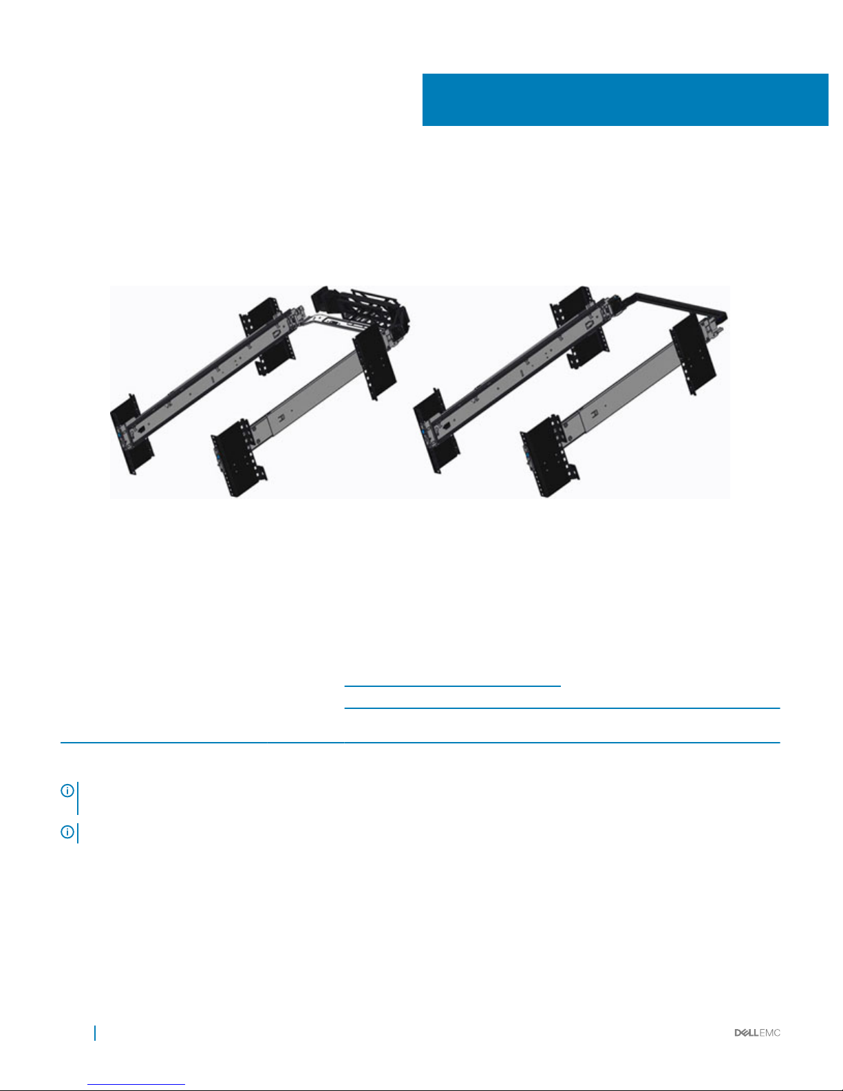
The rail oerings consist of sliding rails only.
The sliding rails allow the system to be fully extended out of the rack for service. There is also an optional Cable Management Arm (CMA)
and optional Strain Relief Bar (SRB).
Figure 7. Sliding rails with optional CMA and optional SRB
One key factor in selecting the proper rails is identifying the type of rack in which they will be installed. Both the sliding rails and the static
rails support tool-less mounting in 19”-wide, EIA-310-E-compliant square hole and unthreaded round hole 4-post racks. Both also support
tooled mounting in threaded hole 4-post racks, but only the static rails, as the more universal solution, support mounting in 2-post (Telco)
racks.
Table 15. Sliding rail
Product Rail
identier
Rail type Mounting
interface
Rail adjustability range (mm) Min rail mounting depth (mm)
Square Round Threaded
min max min max min max Without CMA
or SRB
With
CMA
With SRB
R940 B12 Sliding ReadyRails II 600 894 586 887 600 909 773 926 877
NOTE: Screws are not included in either kit due to the fact that threaded racks are oered with a variety of thread designations.
Users must therefore provide their own screws when mounting the rails in threaded racks.
NOTE: Screw head diameter for the sliding rails must be 10 mm or less.
Cable Management Arm (CMA) and Strain Relief Bar
(SRB)
The optional cable management arm (CMA) and Strain Relief Bar (SRB) organizes and secures the cords and cables exiting the back of the
server. The CMA supports up to medium size cable loads and unfolds to allow the server to extend out of the rack without having to
9
28 Rack Rails
Page 29
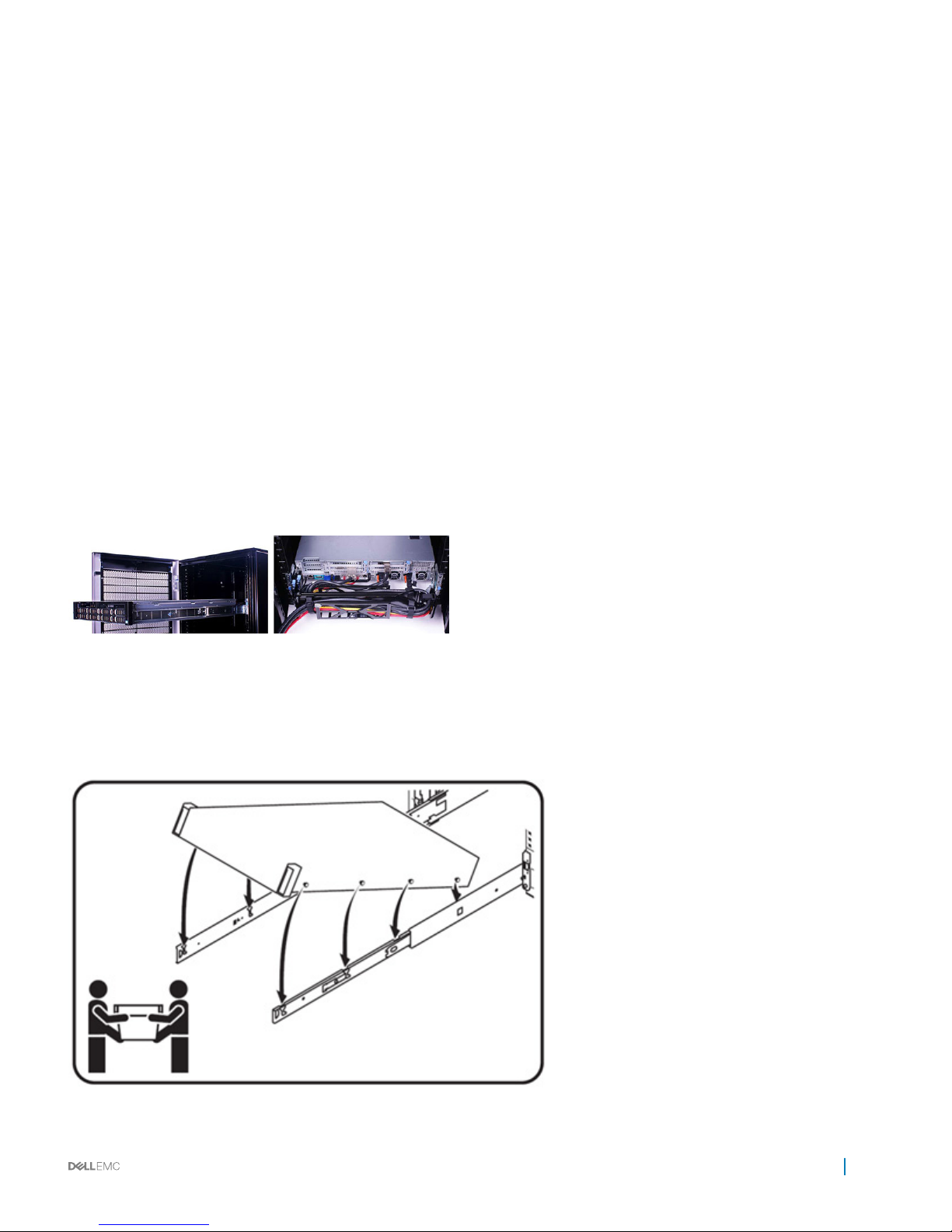
detach the cables. The SRB is a bar that supports large cable loads and also allows the server to extend out of the rack without having to
detach the cables if cable service loops are created.
Some key features of the CMA include:
• Large U-shaped baskets to support dense cable loads
• Open vent pattern for optimal airow
• Ability to be mounted on either side by simply swinging the spring-loaded brackets from one side to the other
• Utilizes hook-and-loop straps rather than plastic tie wraps to eliminate the risk of cable damage during cycling
• Includes a low-prole xed tray to both support and retain the CMA in its fully closed position
• Both the CMA and the tray mount without the use of tools via simple and intuitive snap-in designs
Some key features of the SRB include:
• Sturdy bar that supports large cable loads.
• Controls stresses on connectors.
• Utilizes hook-and-loop straps rather than plastic tie wraps to make securing cables quick and eliminates the risk of cable damage.
• Cables can be segregated into discrete, purpose specic bundles.
• Attaches to the rails without the use of tools via simple and intuitive latching design.
The CMA can be mounted to either side of the sliding rails without the use of tools or the need for conversion. However, it is recommended
that it be mounted on the side opposite to the power supplies to allow easier access to the power supplies and rear hard drives (if
applicable) for service or replacement.
Rack Installation
The sliding rails are a "drop-in" design. This means that the system is installed vertically into the rails by inserting the standos on the sides
of the system into the "J-slots" in the inner rail members with the rails in the fully extended position. As with all 2U systems, a minimum of
two people are required in order to properly install the system in the rails.
Rack Rails
29
Page 30
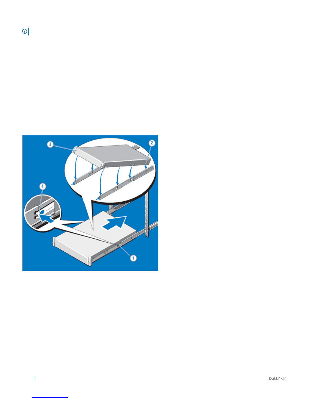
NOTE: The 2U system requires two people for installation due to its heavier weight.
Installing 14G Systems in Sliding Rails
To install the 14G system in sliding rails:
1 Pull the inner slide rails out of the rack until they lock into place.
• Hold the system by its front and back ends and tilt the front end upward slightly.
• Check the window on the sides of both rails to conrm that the heads of the standos are visible before adjusting or releasing
your grip on the back end of the system.
• Use your free hand to hold the rail against the side of the chassis if needed as the system is rotated downward into the remaining
J-slots.
2 Locate the rear rail stando on each side of the system and lower them into the rear J-slots of the slide assembly.
3 Rotate the system downward until all the rail standos are seated in the J-slots.
4 Push the system inward until the lock levers click into place. Press the slide-release lock buttons on both rails and slide the system into
the rack.
30
Rack Rails
Page 31

Supported operating system
Table 16. Supported operating system
Operating system PQM part number
RedHat Enterprise Linux 6.9 Server x86_64 VM93R
RedHat Enterprise Linux 7.3 Server x86_64 V9RKV
Novell SuSE Linux Enterprise Server 11 (with PLDP) SP4 x86_64
YN80M
Novell SuSE Linux Enterprise Server 12 SP2 x86_64 CM3M5
MS, Windows Server 2016 XW2CG
MS, Windows Server 2012 R2 Y1V44
Ubuntu LTS 14.04 N/A
Supported virtualization
Table 17. Virtualization support
Operating system Release Install version
VMware vSphere 2016 U1-N version ESXi
VMware vSphere v6.0 U3-N-1 version ESXi
Citrix Xen Server 7.1.x N/A
10
Supported operating system 31
Page 32

OpenManage systems management
The Dell OpenManage systems management portfolio includes powerful hardware and software management tools and consoles.
OpenManage simplies the lifecycle of deploying, updating, monitoring and maintaining your Dell PowerEdge servers.
Topics:
• iDRAC Lifecycle controller
• Agent-free management
• Agent-based management
• OpenManage consoles
• OpenManage systems management tools, utilities and protocols
• Integration with third-party consoles
• OpenManage connections with third-party consoles
• Server management operations
iDRAC Lifecycle controller
The PowerEdge server provides storage expandability that allows you to adapt to your workload and operational demands. With
comprehensive storage options, the server oer various drive types, internal and external storage controllers, and dierent backplanes for
varied number of drives. The microcontroller is responsible for acting as an interface or gateway between the host system (i.e., server
management software) and the peripheral devices. These peripheral devices, which may or may not be Intelligent Platform Management
Interface (IPMI) compliant, consist of the power supplies, the storage backplane, integrated storage controllers, control panel with semiintelligent display, and Lifecycle Controller.
iDRAC features and comparison
iDRAC9 is available in basic, express, and enterprise options.
Table 18. iDRAC feature comparison
Features iDRAC8
Basic
iDRAC9
Basic
iDRAC8
Express
iDRAC9
Express
iDRAC8
Express for
Blades
iDRAC9
Express for
Blades
iDRAC8
Enterprise
iDRAC9
Enterprise
Interface/Standards
Redsh Yes Yes Yes Yes Yes Yes Yes Yes
IPMI 2.0 Yes Yes Yes Yes Yes Yes Yes Yes
DCMI 1.5 Yes Yes Yes Yes Yes Yes Yes Yes
Web-based GUI—HTML5 Yes Yes Yes Yes Yes Yes Yes Yes
Racadm command line—
local/remote
Yesses Yes Yes Yes Yes Yes Yes Yes
11
32 OpenManage systems management
Page 33

Features iDRAC8
Basic
iDRAC9
Basic
iDRAC8
Express
iDRAC9
Express
iDRAC8
Express for
Blades
iDRAC9
Express for
Blades
iDRAC8
Enterprise
iDRAC9
Enterprise
SMASH-CLP—SSH-only Yes Yes Yes Yes Yes Yes Yes Yes
Telnet Yes Yes Yes Yes Yes Yes Yes Yes
SSH Yes Yes Yes Yes Yes Yes Yes Yes
Serial redirection Yes Yes Yes Yes Yes Yes Yes Yes
WSMAN Yes Yes Yes Yes Yes Yes Yes Yes
Network Time Protocol No Yes Yes Yes Yes Yes Yes
Connectivity
Shared NIC Yes Yes Yes Yes N/A N/A Yes Yes
Dedicated NIC Yes Yes Yes Yes Yes Yes Yes Yes
VLAN tagging Yes Yes Yes Yes Yes Yes Yes Yes
IPv4 Yes Yes Yes Yes Yes Yes Yes Yes
IPv6 Yes Yes Yes Yes Yes Yes Yes Yes
DHCP (new default; no
static IP)
Yes Yes Yes Yes Yes Yes Yes Yes
DHCP with Zero Touch No No No No No No No Yes
Dynamic DNS Yes Yes Yes Yes Yes Yes Yes Yes
OS pass-through Yes Yes Yes Yes Yes Yes Yes Yes
iDRAC Direct-Front panel
USB
Yes Yes Yes Yes Yes Yes Yes Yes
Connection View No Yes No Yes No Yes No Yes
NFS v4 No Yes No Yes No Yes No Yes
SMB3.0 with NTLM v1 and
NTLM v2
No Yes No Yes No Yes No Yes
Security
Role-based authority Yes Yes Yes Yes Yes Yes Yes Yes
Local users Yes Yes Yes Yes Yes Yes Yes Yes
SSL encryption Yes Yes Yes Yes Yes Yes Yes Yes
IP blocking No No Yes Yes Yes Yes Yes Yes
Directory services—AD,
LDAP
No No No No No No Yes Yes
2-factor authentication No No No No No No Yes Yes
Single sign-on No No No No No No Yes Yes
PK authentication No No Yes Yes Yes Yes Yes Yes
FIPS 140-2 Yes Yes Yes Yes Yes Yes Yes Yes
Secure UEFI boot-certicate
management
No Yes No Yes No Yes No Yes
OpenManage systems management 33
Page 34

Features iDRAC8
Basic
iDRAC9
Basic
iDRAC8
Express
iDRAC9
Express
iDRAC8
Express for
Blades
iDRAC9
Express for
Blades
iDRAC8
Enterprise
iDRAC9
Enterprise
Lock down mode No No No No Yes
Unique iDRAC default
password
No Yes No Yes No Yes No Yes
Customizable Security Policy
Banner-login page
No Yes No Yes No Yes No Yes
Quick Sync 2.0-optional auth
for read operations
No Yes No Yes No Yes No Yes
Quick Sync 2.0-add mobile
device number to LCL
No Yes No Yes No Yes No Yes
Remote Presence
Power control Yes Yes Yes Yes Yes Yes Yes Yes
Boot control Yes Yes Yes Yes Yes Yes Yes Yes
Serial-over-LAN Yes Yes Yes Yes Yes Yes Yes Yes
Virtual Media No No No No Yes Yes Yes Yes
Virtual Folders No No No No No No Yes Yes
Remote File Share No No No No No No Yes Yes
Virtual Console No No No No Yes Yes Yes Yes
HTML5 access to virtual
console
No No No No Yes Yes Yes Yes
VNC connection to OS No No No No No No Yes Yes
Quality/bandwidth control No No No No No No Yes Yes
Virtual Console collaboration
—6 users
No No No No No No Yes Yes
Virtual Console chat No No No No No No Yes Yes
Virtual Flash partitions No No No No No No Yes Yes
Group manager No No No No No No No Yes
HTTP/HTTPS support along
with HFS/CIFS
No Yes No Yes No Yes No Yes
Power and Thermal
Real-time power meter Yes Yes Yes Yes Yes Yes Yes Yes
Power thresholds & alerts No No Yes Yes Yes Yes Yes Yes
Real-time power graphing No No Yes Yes Yes Yes Yes Yes
Historical power counters No No Yes Yes Yes Yes Yes Yes
Power capping No No No No No No Yes Yes
Power Center integration No No No No No No Yes Yes
Temperature monitoring Yes Yes Yes Yes Yes Yes Yes Yes
Temperature graphing No No Yes Yes Yes Yes Yes Yes
34 OpenManage systems management
Page 35

Features iDRAC8
Basic
iDRAC9
Basic
iDRAC8
Express
iDRAC9
Express
iDRAC8
Express for
Blades
iDRAC9
Express for
Blades
iDRAC8
Enterprise
iDRAC9
Enterprise
Health Monitoring
Full agent-free monitoring Yes Yes Yes Yes Yes Yes Yes Yes
Predictive failure monitoring Yes Yes Yes Yes Yes Yes Yes Yes
SNMPv1, v2 and v3—traps
and gets
Yes Yes Yes Yes Yes Yes Yes Yes
Email alerting No No Yes Yes Yes Yes Yes Yes
Congurable thresholds Yes Yes Yes Yes Yes Yes Yes Yes
Fan monitoring Yes Yes Yes Yes Yes Yes Yes Yes
Power Supply monitoring Yes Yes Yes Yes Yes Yes Yes Yes
Memory monitoring Yes Yes Yes Yes Yes Yes Yes Yes
CPU monitoring Yes Yes Yes Yes Yes Yes Yes Yes
RAID monitoring Yes Yes Yes Yes Yes Yes Yes Yes
NIC monitoring Yes Yes Yes Yes Yes Yes Yes Yes
HD monitoring—enclosure Yes Yes Yes Yes Yes Yes Yes Yes
Out of Band Performance
Monitoring
No No No No No No Yes Yes
Alerts for excessive SSD
wear
No Yes No Yes No Yes No Yes
Customizable settings for
Exhaust Temperature
No Yes No Yes No Yes No Yes
Update
Remote agent-free update Yes Yes Yes Yes Yes Yes Yes Yes
Embedded update tools Yes Yes Yes Yes Yes Yes Yes Yes
Sync with repository—
scheduled updates
No No No No No No Yes Yes
Auto update No No No No No No Yes Yes
Improved PSU rmware
updates
No Yes No Yes No Yes No Yes
Deployment and Conguration
Local conguration via F10 Yes Yes Yes Yes Yes Yes Yes Yes
Embedded OS deployment
tools
Yes Yes Yes Yes Yes Yes Yes Yes
Embedded conguration
tools
Yes Yes Yes Yes Yes Yes Yes Yes
AutoDiscovery No No Yes Yes Yes Yes Yes Yes
Remote OS deployment No No Yes Yes Yes Yes Yes Yes
Embedded driver pack Yes Yes Yes Yes Yes Yes Yes Yes
OpenManage systems management 35
Page 36

Features iDRAC8
Basic
iDRAC9
Basic
iDRAC8
Express
iDRAC9
Express
iDRAC8
Express for
Blades
iDRAC9
Express for
Blades
iDRAC8
Enterprise
iDRAC9
Enterprise
Full conguration inventory Yes Yes Yes Yes Yes Yes Yes Yes
Inventory export Yes Yes Yes Yes Yes Yes Yes Yes
Remote conguration Yes Yes Yes Yes Yes Yes Yes Yes
Zerotouch conguration No No No No No No Yes Yes
System Retire/Repurpose Yes Yes Yes Yes Yes Yes Yes Yes
Server Conguration Prole
in GUI
No Yes No Yes No Yes No
Diagnostics, Service and Logging
Embedded diagnostic tools Yes Yes Yes Yes Yes Yes Yes Yes
Part Replacement No No Yes Yes Yes Yes Yes Yes
Server Conguration Backup No No No No No No Yes Yes
Server Conguration Restore Yes Yes Yes Yes Yes Yes Yes Yes
Easy Restore—system
conguration
Yes Yes Yes Yes Yes Yes Yes Yes
Easy Restore Auto Timeout No Yes No Yes No Yes No Yes
LED health status indicator No No No No No No No No
LCD screen—iDRAC9
requires optional bezel
Yes Yes Yes Yes N/A N/A Yes Yes
Quick Sync—require NFC
bezel
Yes No Yes No N/A No Yes No
Quick Sync 2.0—requires
BLE/WiFi hardware
No Yes No Yes No N/A No Yes
iDRAC Direct—front USB
mgmt port
Yes Yes Yes Yes Yes Yes Yes Yes
iDRAC Service Module (iSM)
embedded
No Yes No Yes No Yes No Yes
iSM to inband alert
forwarding to consoles
No Yes No Yes No Yes No Yes
Crash screen capture No No Yes Yes Yes Yes Yes Yes
Crash video capture No No No No No No Yes Yes
Boot capture No No No No No No Yes Yes
Manual reset for iDRAC—
LCD ID button
Yes Yes Yes Yes Yes Yes Yes Yes
Remote reset for iDRAC—
requires iSM
Yes Yes Yes Yes Yes Yes Yes Yes
Virtual NMI Yes Yes Yes Yes Yes Yes Yes Yes
OS watchdog Yes Yes Yes Yes Yes Yes Yes Yes
36 OpenManage systems management
Page 37

Features iDRAC8
Basic
iDRAC9
Basic
iDRAC8
Express
iDRAC9
Express
iDRAC8
Express for
Blades
iDRAC9
Express for
Blades
iDRAC8
Enterprise
iDRAC9
Enterprise
SupportAssist Report—
embedded
Yes Yes Yes Yes Yes Yes Yes Yes
System Event Log Yes Yes Yes Yes Yes Yes Yes Yes
Lifecycle Log Yes Yes Yes Yes Yes Yes Yes Yes
Enhanced logging in the
Lifecycle controller log
Yes Yes Yes Yes Yes Yes Yes Yes
Work notes Yes Yes Yes Yes Yes Yes Yes Yes
Remote Syslog No No No No No No Yes Yes
License management Yes Yes Yes Yes Yes Yes Yes Yes
Improved customer experience
iDRAC -Faster processor,
more memory
No Yes No Yes No Yes No Yes
GUI rendered in HTML5 No Yes No Yes No Yes No Yes
Add BIOS conguration to
iDRAC GUI
No Yes No Yes No Yes No Yes
iDRAC support for SW RAID
licensing
No Yes No Yes No Yes No Yes
Agent-free management
As Dell EMC PowerEdge servers have embedded server lifecycle management, in many cases, there is no need to install an OpenManage
systems management software agent into the operating system of a PowerEdge server. This greatly simplies and streamlines the
management footprint.
Agent-based management
Most systems management solutions require pieces of software, called agents, to be installed on each node in order to be managed within
the IT environment. Additionally, the same agent is often used as a local interface into the hardware health and may be accessed remotely
as a management interface, typically referred to as a one-to-one interface. For customers that continue to use agent-based solutions, Dell
provides OpenManage Server Administrator.
OpenManage consoles
The central console in a systems management solution is often referred to as the one-to-many console. The central console provides a
rapid view and insight into the overall health of all systems in the IT environment. The Dell EMC systems management portfolio includes
several powerful consoles, depending upon your needs, including the following:
• Dell OpenManage Essentials—OpenManage Essentials (OME) is a systems management console that provides a comprehensive view
of Dell systems, devices, and components in an enterprise network. It is used to monitor Dell PowerEdge servers, EqualLogic and
PowerVault storage, and PowerConnect™ switches; to update and congure Dell servers; and to create asset reports. OpenManage
Essentials also communicates health status alerts for Dell servers, storage, and network devices to the Dell KACE™ K1000 service desk.
OpenManage Essentials is available as a no-charge software download from Dell.com/Support. When connected through OME, you
can use Dell OpenManage Mobile (OMM) to securely perform a subset of data center monitoring and remediation tasks from a mobile
device.
• OpenManage Power Center—Dell’s power management solution, the Dell OpenManage Power Center (OMPC) management console,
provides increased visibility to power consumption, anomalies, and utilization through ne-grained instrumentation. This enables
OpenManage systems management
37
Page 38

increased control, improved rack density, faster response times, greater accuracy, and broader decision-making intelligence than would
otherwise be possible. When used with a suitably licensed PowerEdge server (with a Dell iDRAC Enterprise license), OMPC leverages
Intel Node Manager technology for platform-level power reporting and capping of Intel chipsets. Power Center then communicates
with iDRAC to provide node, rack, row or data-center level aggregation of power-management data, as well as execution of control
policy — making it easy for IT professionals to identify areas to gain eciencies and cut wasteful costs.
OpenManage systems management tools, utilities and
protocols
OpenManage systems management tools and utilities consist of the following:
• Dell EMC Repository Manager: The Dell EMC Repository Manager (RM) is a stand-alone GUI-based productivity tool that helps
simplify the process of managing downloads and baseline BIOS, rmware and driver updates. Repository Manager can create
deployment disks as well as create and manage customized repositories.
• Dell EMC Update Packages: The Dell EMC Update Packages (DUP) is a self-contained executable in a standard package format that
updates a software element on a Dell server such as the BIOS, a driver, rmware and other software updates.
• Dell EMC OpenManage Deployment Toolkit: The Dell EMC OpenManage Deployment Toolkit (DTK) is a CLI-based tool that includes a
set of utilities for conguring and deploying Dell PowerEdge systems, and can be used to build scripted, unattended OS installations to
deploy large numbers of servers in a reliable fashion.
• RACADM: The RACADM command-line utility provides a scriptable interface that allows you to locally or remotely congure iDRAC7.
• IPMITool: IPMITool includes scriptable console application programs used to control and manage remote systems using the IPMI version
1.5 and later protocol.
• Web Services for Management (WSMAN): WSMAN is a SOAP-XML–based protocol for exchanging system management
information. Dell's implementation provides remote management capabilities through a secure and standards-based Web Services–
Management (WS-MAN) interface to PowerEdge servers and blade server node chassis.
Integration with third-party consoles
OpenManage provides integration with several leading third-party consoles, including:
• OpenManage Integration Suite for Microsoft System Center—This suite helps you further streamline, automate and simplify your
most essential IT management tasks. For more information, visit http://www.dell.com/learn/us/en/04/solutions/dcsm-microsoft-
system-center.
• OpenManage Integration for VMware vCenter—This plug-in allows IT administrators to monitor, provision, and manage the physical
PowerEdge server hardware and rmware from a dedicated menu accessed through the VMware vCenter console using the same rolebased access control model as vCenter, combining physical server management. For more information, visit http://www.dell.com/
learn/us/en/04/virtualization/management-plug-in-for-vmware-vcenter.
• BMC Software—Dell EMC and BMC Software work together to simplify IT by ensuring tight integration between Dell EMC server,
storage, and network management functionality and the BMC Software process and data center automation products.
OpenManage connections with third-party consoles
OpenManage Connections gives you an easy path to adding support for third-party devices, so you can continue to use your existing
management tools while easily adding server systems to your existing IT environment. Integrate new systems at your own pace. Manage
new servers and storage with your legacy management tools, while extending the useful life of your existing resources. With OpenManage
Connections you can add monitoring and troubleshooting to your IT infrastructure.
• OpenManage Connection for Nagios
• OpenManage Connection for Oracle
• OpenManage Connection for HP
• OpenManage Connection for IBM
• OpenManage Connection for CA
For more information on these OpenManage Connections, visit http://www.dell.com/learn/us/en/04/solutions/dcsm-partner-consoles.
38
OpenManage systems management
Page 39
Server management operations
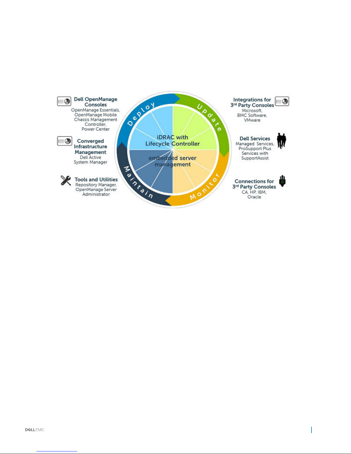
OpenManage systems management is centered on automating the server management lifecycle — deploy, update, monitor and maintain.
To manage an infrastructure properly and eciently, you must perform all of these functions easily and quickly. iDRAC9 with Lifecycle
Controller technology provides you with these intelligent capabilities embedded within the server infrastructure. This allows you to invest
more time and energy on business improvements and less on maintenance. Figure 16 illustrates the various operations that can be
performed during the server’s lifecycle.
Figure 8. Systems management server lifecycle
Table 19. One-to-one and one-to-many operations
Operation One-to-one One-to-many
Deploy
• Lifecycle Controller GUI
• DTK
• OpenManage Integration for VMware vCenter
• OpenManage Integration for BMC BladeLogic
• OpenManage Integration for Microsoft System
Center Conguration Manager
Update
• iDRAC9 with Lifecycle Controller
• Repository Manager
• DUP
• SUU
• OpenManage Integration for VMware vCenter
• OpenManage Essentials
• OpenManage Integration for Microsoft System
Center Conguration Manager
Monitor
• iDRAC9 with Lifecycle Controller
• OMSA
• OpenManage Essentials
• OpenManage Power Center
• OpenManage Integration for VMware vCenter
• OpenManage Integration for Microsoft System
Center Operations Manager
Maintain
• iDRAC9 with Lifecycle Controller
• IPMI
• Lifecycle Controller Remote Services Remediate
and replace parts:
• OpenManage Integration for Microsoft System
Center Virtual Machine Manager (SCVMM)
OpenManage systems management 39
Page 40

• Server Pro Management Pack and Lifecycle
Controller Integration (DLCI)
For additional detailed information on Dell’s systems management portfolio, visit Dell.com/OpenManage.
40 OpenManage systems management
Page 41
Appendix A. Additional specications
Chassis dimensions
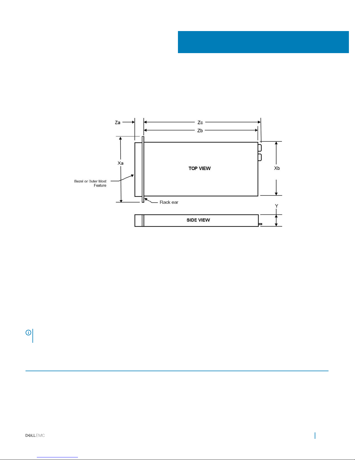
The following image shows the dimensions of the PowerEdge R940 chassis:
Figure 9. PowerEdge R940 chassis dimension
• Xa: 482.0 mm
• Xb: 434.0 mm
• Y: 130.3 mm
• Za (with bezel): 35.84 mm
• Za (without bezel): 22.0 mm
• Zb: 762.2 mm
• Zc: 777.046 mm
Environmental specications
NOTE
: For additional information about environmental measurements for specic system congurations, see Dell.com/
environmental_datasheets.
Table 20. Temperature specications
Temperature Specications
Storage –40°C to 65°C (–40°F to 149°F)
Continuous operation (for altitude less than 950 m or 3117
ft)
10°C to 35°C (50°F to 95°F) with no direct sunlight on the equipment.
Maximum temperature gradient (operating and storage) 20°C/h (68°F/h)
12
Appendix A. Additional specications 41
Page 42

Table 21. Relative humidity specications
Relative humidity Specications
Storage 5% to 95% RH with 33°C (91°F) maximum dew point. Atmosphere must be
non-condensing at all times.
Operating 10% to 80% relative humidity with 26°C (78.8°F) maximum dew point.
Table 22. Maximum vibration specications
Maximum vibration Specications
Operating 0.26 G
rms
at 5 Hz to 350 Hz (all operation orientations).
Storage 1.87 G
rms
at 10 Hz to 500 Hz for 15 min (all six sides tested).
Table 23. Maximum shock specications
Maximum shock Specications
Operating One shock pulse in the positive z axis of 40 G for 2.3 ms in all operational
orientations.
Storage Six consecutively executed shock pulses in the positive and negative x, y,
and z axes (one pulse on each side of the system) of 71 G for up to 2 ms.
Table 24. Maximum altitude specications
Maximum altitude Specications
Operating
3048 m (10,000 ft)
Storage 12,000 m (39,370 ft)
Table 25. Operating temperature de-rating specications
Operating temperature de-rating Specications
Up to 35°C (95°F) Maximum temperature is reduced by 1°C/300 m (1°F/547 ft) above 950 m
(3,117 ft).
35°C to 40°C (95°F to 104°F) Maximum temperature is reduced by 1°C/175 m (1°F/319 ft) above 950 m
(3,117 ft).
40°C to 45°C (104°F to 113°F) Maximum temperature is reduced by 1°C/125 m (1°F/228 ft) above 950 m
(3,117 ft).
Particulate and gaseous contamination specications
The following table denes the limitations that help avoid any equipment damage or failure from particulates and gaseous contamination. If
the levels of particulates or gaseous pollution exceed the specied limitations and result in equipment damage or failure, you may need to
rectify the environmental conditions. Re-mediation of environmental conditions is the responsibility of the customer.
42
Appendix A. Additional specications
Page 43

Table 26. Particulate contamination specications
Particulate contamination Specications
Air ltration Data center air ltration as dened by ISO Class 8 per ISO 14644-1 with a
95% upper condence limit.
NOTE: This condition applies to data center environments only. Air
ltration requirements do not apply to IT equipment designed to be
used outside a data center, in environments such as an oce or
factory oor.
NOTE: Air entering the data center must have MERV11 or MERV13
ltration.
Conductive dust Air must be free of conductive dust, zinc whiskers, or other conductive
particles.
NOTE: This condition applies to data center and non-data center
environments.
Corrosive dust
• Air must be free of corrosive dust.
• Residual dust present in the air must have a deliquescent point less than
60% relative humidity.
NOTE: This condition applies to data center and non-data center
environments.
Table 27. Gaseous contamination specications
Gaseous contamination Specications
Copper coupon corrosion rate <300 Å/month per Class G1 as dened by ANSI/ISA71.04-1985.
Silver coupon corrosion rate <200 Å/month as dened by AHSRAE TC9.9.
NOTE: Maximum corrosive contaminant levels measured at ≤50% relative humidity.
Standard operating temperature
Table 28. Standard operating temperature
specications
Standard operating temperature Specications
Continuous operation (for altitude less than 950 m or 3117
ft)
10°C to 35°C (50°F to 95°F) with no direct sunlight on the equipment.
Humidity percentage range 10% to 80% Relative Humidity with 26°C (78.8°F) maximum dew point.
Appendix A. Additional specications 43
Page 44

Expanded operating temperature
Table 29. Expanded operating temperature specications
Expanded operating temperature Specications
< 10% of annual operating hours 5°C to 40°C at 5% to 85% RH with 29°C dew point.
NOTE: Outside the standard operating temperature (10°C to
35°C), the system can operate continuously in temperatures as low
as 5°C and as high as 40°C.
For temperatures between 35°C and 40°C, de-rate maximum allowable dry
bulb temperature by 1°C per 175 m above 950 m (1°F per 319 ft).
< 1% of annual operating hours –5°C to 45°C at 5% to 90% RH with 29°C dew point.
NOTE: Outside the standard operating temperature (10°C to
35°C), the system can operate down to –5°C or up to 45°C for a
maximum of 1% of its annual operating hours.
For temperatures between 40°C and 45°C, de-rate maximum allowable
temperature by 1°C per 125 m above 950 m (1°F per 228 ft).
NOTE: When operating in the expanded temperature range, system performance may be impacted.
NOTE: When operating in the expanded temperature range, ambient temperature warnings maybe reported on the LCD panel and
in the System Event Log.
Video specications
Table 30. R940 video
specications
Resolution Refresh rate Horizontal frequency Pixel clock
1024 x 768 60 Hz 48.4 kHz 65.0 MHz
1280 x 800 60 Hz 49.7 kHz 83.5 MHz
1280 x 1024 60 Hz 64.0 kHz 108.0 MHz
1360 x 768 60 Hz 47.71 kHz 85.5 M
1440 x 900 60 Hz 55.9 kHz 106.5 MHz
1600 x 900 60 Hz (RB) 55.54 kHz 97.75 M
1600 x 1200 60 Hz 75.0 kHz 162.0 MHz
1680 x 1050 60 Hz (RB) 64.7 kHz 119.0 MHz
1920 x 1080 60 Hz 67.158 kHz 173.0 MHz
1920 x 1200 60 60 Hz 74.556 kHz 193.25 MHz
*RB-Reduced Blanking for Digital Displays requiring less blank time. This was introduced for Signal Integrity improvements by reducing Pixel
Clock rates for VGA-Analog input devices.
44
Appendix A. Additional specications
Page 45

USB peripherals
USB peripherals are supported through the front and back USB ports on the R940. The front ports, back and internal ports are USB 3.0
compliant.
Appendix A. Additional specications 45
Page 46

Appendix B. Standards compliance
Table 31. Industry standard documents
Standard URL for information and specications
ACPI Advance Conguration and Power Interface Specication,
v2.0c
acpi.info
Ethernet IEEE 802.3-2005 standards.ieee.org/getieee802/802.3.html
HDG Hardware Design Guide Version 3.0 for Microsoft Windows
Server
microsoft.com/whdc/system/platform/pcdesign/desguide/
serverdg.mspx
IPMI Intelligent Platform Management Interface, v2.0 intel.com/design/servers/ipmi
DDR4 Memory DDR4 SDRAM Specication jedec.org/standards-documents/docs/jesd79-4.pdf
PCI Express PCI Express Base Specication Rev. 2.0 and 3.0 pcisig.com/specications/pciexpress
PMBus Power System Management Protocol Specication, v1.2 pmbus.info/specs.html
SAS Serial Attached SCSI, v1.1 t10.org
SATA Serial ATA Rev. 2.6; SATA II, SATA 1.0a Extensions, Rev. 1.2 sata-io.org
SMBIOS System Management BIOS Reference Specication, v2.7 dmtf.org/standards/smbios
TPM Trusted Platform Module Specication, v1.2 and v2.0 trustedcomputinggroup.org
UEFI Unied Extensible Firmware Interface Specication, v2.1 ue.org/specications
USB Universal Serial Bus Specication, Rev. 2.0 usb.org/developers/docs
13
46 Appendix B. Standards compliance
Page 47

Appendix C Additional resources
Table 32. Additional resources
Resource Description of contents Location
Owner’s Manual
This manual, available in PDF format, provides the following
information:
• Chassis features
• System Setup program
• System messages
• System codes and indicators
• System BIOS
• Remove and replace procedures
• Troubleshooting
• Diagnostics
• Jumpers and connectors
Dell.com/Support/Manuals
Getting Started Guide
This guide ships with the system, and is also available in PDF
format. This guide provides the following information:
• Initial setup steps
• Key system features
• Technical specications
Dell.com/Support/Manuals
Rack Installation Instructions This document ships with the rack kits, and provides instructions
for installing a server in a rack.
Dell.com/Support/Manuals
Information Update This document ships with the system, is also available in PDF
format online, and provides information on system updates.
Dell.com/Support/Manuals
System Information Label The system information label documents the system board layout
and system jumper settings. Text is minimized due to space
limitations and translation considerations. The label size is
standardized across platforms.
Inside the system chassis cover
Quick Resource Locator (QRL) This code on the chassis can be scanned by a phone application to
access additional information and resources for the server,
including videos, reference materials, service tag information, and
Dell contact information.
Inside the system chassis cover
Energy Smart Solution Advisor
(ESSA)
The Dell online ESSA enables easier and more meaningful
estimates to help you determine the most ecient conguration
possible. Use ESSA to calculate the power consumption of your
hardware, power infrastructure, and storage.
Dell.com/calc
14
Appendix C Additional resources 47
Page 48

Appendix D. Support and deployment services
Server Deployment Services
Our Server Deployment Services can maximize the value of your servers quickly using our expert server deployment engineers. With over
10,000 server deployment projects each year, we have experience, best practices, and comprehensive deployment tools to install,
congure, and integrate your new solution optimally and correctly. Our deployment experts will assess your environment and understand
your goals, then design and integrate your server solution for you.
Table 33. Server deployment capabilities
Server Installation Server Integration
Place single server in target workspace Yes
Rack, cable, and label servers Yes
Install image Yes
Connect to network Yes Yes
Test and validate connection Yes Yes
Install operating system Yes
Install applications Yes
Perform advanced conguration services Yes
Remote conguration services Yes
Virtualization Yes
Converged infrastructure Yes
Test and validate data center integration Yes
Remote Consulting Services
When you are in the nal stages of your PowerEdge server implementation, you can rely on Dell Remote Consulting and our certied
technical experts to help you optimize your conguration with best practices for your software, virtualization, server, storage, networking,
and systems management.
Data Migration Service
Protect your business and data with our single point of contact to manage your data migration project. Your project manager will work with
our experienced team of experts to create a plan using industry-leading tools and proven processes based on global best practices to
migrate your existing les and data, so your business gets up and running quickly and smoothly.
15
48 Appendix D. Support and deployment services
Page 49
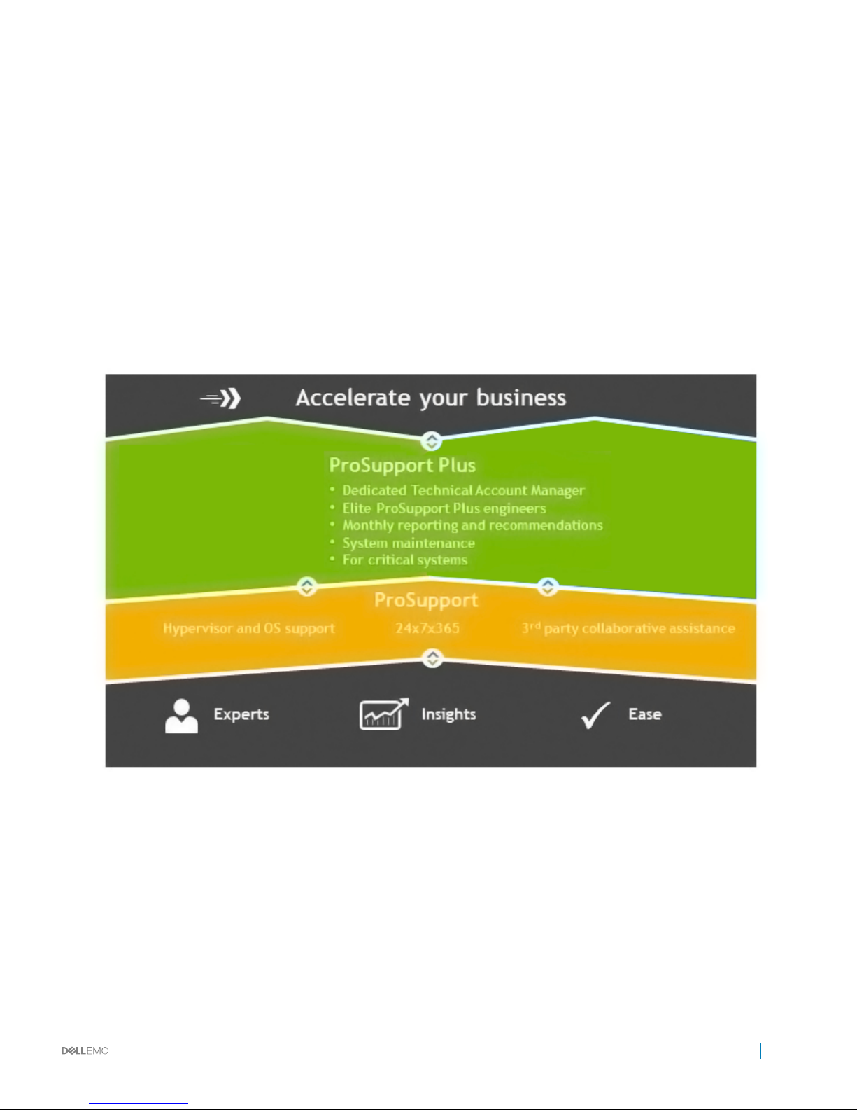
ProSupport Plus (for business-critical servers)
When you purchase your PowerEdge server, we recommend ProSupport Plus, our proactive and preventative support for your businesscritical systems. ProSupport Plus provides you with all the benets of ProSupport, plus access to a dedicated Technical Account Manager
and our elite ProSupport Plus engineers. ProSupport Plus gives you quick and ecient resolutions, working along with our SupportAssist
technology that enables us to get ahead of issues in your environment before they become problems.
ProSupport Enterprise Suite
With Dell EMC ProSupport Services, we can help you keep your operation running smoothly, so you can focus on running your business.
We will help you maintain peak performance and availability of your most essential workloads. Dell EMC ProSupport is a suite of support
services that enable you to build the solution that is right for your organization. Choose support models based on how you use technology
and where you want to allocate resources. From the desktop to the data center, address everyday IT challenges, such as unplanned
downtime, mission-critical needs, data and asset protection, support planning, resource allocation, software application management and
more. Optimize your IT resources by choosing the right support model.
Figure 10. ProSupport Enterprise Suite
ProSupport
Our ProSupport service oers highly trained experts around the clock and around the globe to address your IT needs. We will help you
minimize disruptions and maximize availability of your PowerEdge server workloads with:
• 24x7x365 access to certied hardware experts
• Collaborative support assistance with over 195 third-party vendors
• Hypervisor and operating system support
• Onsite parts and labor response options including next business day or four-hour mission critical
Appendix D. Support and deployment services
49
Page 50
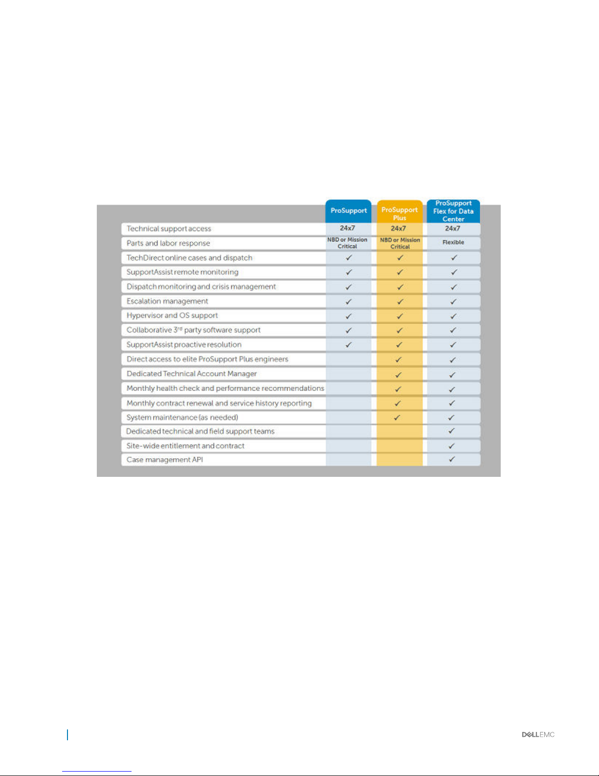
ProSupport Flex for Data Center
ProSupport Flex for Data Center oers exible site-wide support for hyperscale data centers with more than 1,000 assets. Built on standard
ProSupport components, Flex for Data Center leverages our global scale while being tailored to suit your needs. While not for everyone, it
oers a exible solution for those with large and complex environments. When you choose ProSupport Flex for Data Center, you will get:
• Enterprise-wide support that covers your entire data center.
• A dedicated Technical Account Manager with remote, on-site, part-time and full-time options.
• Dedicated elite ProSupport Flex technical and eld engineers who are trained on your environment and congurations.
• Flexible on-site support and parts options that t your operational model
• A tailored support plan for your operations sta.
Figure 11.
ProSupport Enterprise Suite comparison
Additional professional services
Dell Education Services
Dell Education Services oers the PowerEdge server training courses designed to help you achieve more with your hardware investment.
The curriculum is designed in conjunction with the server development team, as well as Dell’s technical support team, to ensure that the
training delivers the information and practical, hands-on skills you and your team need to condently manage and maintain your Dell server
solution. To learn more or register for a class today, visit LearnDell.com/Server.
Dell Global Infrastructure Consulting Services
Dell Global Infrastructure Consulting Services use skilled solution architects, innovative tools, automated analysis and Dell’s intellectual
property to give you rapid insight into the root causes of unnecessary complexity. We seek better answers than traditional service models,
50
Appendix D. Support and deployment services
Page 51

and our strategy is to help you quickly identify high-impact, short-duration projects that deliver return on investment (ROI) and free up
resources. The results are practical, action-oriented plans with specic, predictable, measurable outcomes. From data center optimization to
server virtualization to systems management, our consulting services can help you build a more ecient enterprise.
Dell managed services
Dell Managed Services are a modular set of lifecycle services designed to help you automate and centrally congure, deploy, and manage
your day-to-day data center operations. These services extend your existing on-premise IT infrastructure with o-premise cloud services
designed to better address challenges with mobility, highly distributed organizations, security, compliance, business continuity, and disaster
preparedness.
Appendix D. Support and deployment services 51
 Loading...