

Dell PC6224, PC6224F, PC6224P, PC6248, PC6248P User Manual

Dell™ PowerConnect™
6200 Series Stackable Switches
Getting Started Guide
使用入门指南
Příručka Začínáme
Guide de mise en route
Erste Schritte
Οδηγός για γρήγορο ξεκίνηµα
はじめに
시작 설명서
Instrukcja uruchomienia
Models PC6224, PC6248, PC6224P, PC6248P, and PC6224F
www.dell.com | support.dell.com
Guía de introducción
Başlangıç Kılavuzu


Dell™ PowerConnect™
6200 Series Stackable Switches
Getting Started Guide
Models PC6224, PC6248, PC6224P, PC6248P, and PC6224F
www.dell.com | support.dell.com

Notes, Notices, and Cautions
NOTE: A NOTE indicates important information that helps you make better use of your computer.
NOTICE: A NOTICE indicates either potential damage to hardware or loss of data and tells you how to avoid the problem.
CAUTION: A CAUTION indicates a potential for property damage, personal injury, or death.
____________________
Information in this document is subject to change without notice.
© 2007 Dell Inc. All rights reserved.
Reproduction in any manner whatsoever without the written permission of Dell Inc. is strictly forbidden.
Trademarks used in this text: Dell, the DELL logo, and PowerConnect are trademarks of Dell Inc.; Microsoft and Windows are registered
trademarks of Microsoft Corporation.
Other trademarks and trade names may be used in this document to refer to either the entities claiming the marks and names or their products.
Dell Inc. disclaims any proprietary interest in trademarks and trade names other than its own.
Models PC6224, PC6248, PC6224P, PC6248P, and PC6224F
September 2007 P/N YC897 Rev. A02

Contents
1 Installation
Site Preparation . . . . . . . . . . . . . . . . . . . . . . . . . . . . . . 5
Unpacking the Switch
Package Contents
Unpacking Steps
Mounting the Switch
Installing in a Rack
Installing as a Free-standing Switch
Connecting a Switch to a Terminal
Connecting a Switch to a Power Supply
Assembling a Stack
. . . . . . . . . . . . . . . . . . . . . . . . . . . 5
. . . . . . . . . . . . . . . . . . . . . . . . . . . 5
. . . . . . . . . . . . . . . . . . . . . . . . . . . 6
. . . . . . . . . . . . . . . . . . . . . . . . . . . . 6
. . . . . . . . . . . . . . . . . . . . . . . . . . 6
. . . . . . . . . . . . . . . . . . 7
. . . . . . . . . . . . . . . . . . . . . 7
. . . . . . . . . . . . . . . . . . 7
. . . . . . . . . . . . . . . . . . . . . . . . . . . . 8
2 Starting and Configuring the Switch
Connecting the Terminal to the Switch . . . . . . . . . . . . . . . . . . . 10
Booting the Switch
Initial Configuration
Initial Configuration Procedure
Example Session
. . . . . . . . . . . . . . . . . . . . . . . . . . . . 11
. . . . . . . . . . . . . . . . . . . . . . . . . . . . 12
. . . . . . . . . . . . . . . . . . . . . 12
. . . . . . . . . . . . . . . . . . . . . . . . . . . 13
Contents 3

3 Managing a Stack
Master and Member Switches . . . . . . . . . . . . . . . . . . . . . . . 16
Stack Startup
Topology Discovery
Auto Stack ID Assignment
Firmware Version Checking
System Initialization
CLI/ Telnet/ Web Interface
Insertion and Removal of Switches
Operating as Standalone Switch
Stack ID Renumbering
User Controls
. . . . . . . . . . . . . . . . . . . . . . . . . . . . . . . 16
. . . . . . . . . . . . . . . . . . . . . . . . . . 16
. . . . . . . . . . . . . . . . . . . . . . . 16
. . . . . . . . . . . . . . . . . . . . . . 16
. . . . . . . . . . . . . . . . . . . . . . . . . . 17
. . . . . . . . . . . . . . . . . . . . . . . . . 17
. . . . . . . . . . . . . . . . . . . 17
. . . . . . . . . . . . . . . . . . . . 17
. . . . . . . . . . . . . . . . . . . . . . . . . 17
. . . . . . . . . . . . . . . . . . . . . . . . . . . . . . . 18
4 Front Panels and LEDs
Front Panels . . . . . . . . . . . . . . . . . . . . . . . . . . . . . . . . 19
LEDs
. . . . . . . . . . . . . . . . . . . . . . . . . . . . . . . . . . . 20
Systems LEDs
RJ-45 LEDs (PoE)
XFP LED
SFP LED
. . . . . . . . . . . . . . . . . . . . . . . . . . . . . 20
. . . . . . . . . . . . . . . . . . . . . . . . . . . 21
. . . . . . . . . . . . . . . . . . . . . . . . . . . . . . . 21
. . . . . . . . . . . . . . . . . . . . . . . . . . . . . . . 21
4 Contents

Installation
This document provides basic information to install, configure, and operate Dell™ PowerConnect™ PC6224,
PC6248, PC6224P, PC6248P, and PC6224F systems. For more information, see the
available on your
updates on documentation and firmware.
User Documentation
CD, or check the Dell Support web site at
User's Guide
support.dell.com
Site Preparation
PowerConnect 6200 series switches can be mounted in a standard 48.26-cm (19-inch) rack or left freestanding
(placed on a flat surface). These switches can function as stand-alone switches. They can also be installed as a
stack of switches that function, and are managed, as a single entity.
Before installing the switch or switches, make sure that the chosen installation location meets the following site
requirements:
•
Power
— The switch is installed near an easily accessible 100–250 VAC, 50–60 Hz outlet.
•
Clearance
power connections, and ventilation.
•
Cabling
amplifiers, power lines, and fluorescent lighting fixtures.
•
Ambient
humidity of up to 95 percent, non-condensing.
— There is adequate front and rear clearance for operator access. Allow clearance for cabling,
— The cabling is routed to avoid sources of electrical noise such as radio transmitters, broadcast
— The ambient switch operating temperature range is 0 to 45ºC (32 to 113ºF) at a relative
Unpacking the Switch
, which is
for the latest
Package Contents
When unpacking each switch, make sure that the following items are included:
• One PowerConnect switch
• One AC power cable
• One RS-232 cable
• One rack-mount kit for rack installation (two mounting brackets, bolts, and cage nuts)
• One set of self-adhesive rubber pads for the free-standing switch (four pads are included)
User Documentation
•
• Getting Started Guide
• Product Information Guide
CD
Getting Started Guide 5

Unpacking Steps
NOTE: Before unpacking the switch, inspect the container and immediately report any evidence of damage.
Place the container on a clean, flat surface and cut all straps securing the container.
1
2
Open the container or remove the container top.
3
Carefully remove the switch from the container and place it on a secure and clean surface.
4
Remove all packing material.
5
Inspect the product and accessories for damage.
Mounting the Switch
www.dell.com | support.dell.com
CAUTION: Read the safety information in the Product Information Guide as well as the safety information for other
switches that connect to or support the switch.
The AC and DC power connectors are on the back panel of the switch. We recommend connecting a redundant
power supply, such as the PowerConnect RPS-600 for non-PoE switches or the PowerConnect EPS-470 for PoE
switches.
Installing in a Rack
CAUTION: Do not use rack mounting kits to suspend the switch from under a table or desk, or attach it to a wall.
CAUTION: Disconnect all cables from the switch before continuing. Remove all self-adhesive pads from the
underside of the switch, if they have been attached.
CAUTION: When mounting multiple switches into a rack, mount the switches from the bottom up.
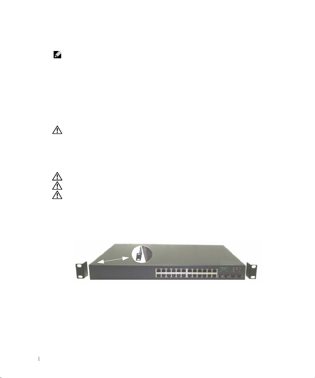
Place the supplied rack-mounting bracket on one side of the switch, ensuring that the mounting holes on
1
the switch line up to the mounting holes in the rack-mounting bracket. Figure 1-1 illustrates where to
mount the brackets.
Figure 1-1. Attaching the Brackets
2
Insert the supplied bolts into the rack-mounting holes and tighten with a screwdriver.
3
Repeat the process for the rack-mounting bracket on the other side of the switch.
6 Getting Started Guide

4
Insert the switch into the 48.26 cm (19 inch) rack, ensuring that the rack-mounting holes on the switch line
up to the mounting holes in the rack.
5
Secure the switch to the rack with either the rack bolts or cage nuts and cage nut bolts with washers
(depending on the kind of rack you have). Fasten the bolts on bottom before fastening the bolts on top.
NOTICE: Make sure that the ventilation holes are not obstructed.
CAUTION: Make sure that the supplied rack bolts fit the pre-threaded holes in the rack.
Installing as a Free-standing Switch
NOTICE: We strongly recommend mounting the switch in a rack.
Install the switch on a flat surface if you are not installing it in a rack. The surface must be able to support
the weight of the switch and the switch cables. The switch is supplied with four self-adhesive rubber pads.
1
Attach the self-adhesive rubber pads on each location marked on the bottom of the switch.
2
Set the switch on a flat surface, and make sure that it has proper ventilation by leaving 5 cm (2 inches)
on each side and 13 cm (5 inches) at the back.
Connecting a Switch to a Terminal
1
Connect the supplied RS-232 cable to a VT100 terminal or to the serial connector of a personal computer
running VT100 terminal emulation software.
2
Connect the female DB-9 connector at the other end of the RS-232 crossover cable to the serial port
connector on the rear of the switch.
NOTE: If you are installing a stack of switches, connect the terminal to the Master Switch. This switch will light the
Master Switch LED, the top left LED in the array on the front panel. When a stack is powered up for the first time, the
switches elect the Master Switch, which may occupy any location in the stack. If you connect the terminal to a member
switch, you will not be able to use the CLI.
Connecting a Switch to a Power Supply
CAUTION: Read the safety information in the Product Information Guide as well as the safety information for other
switches that connect to or support the switch.
Connect the supplied AC power cable to the AC power connector located on the back panel.
1
Figure 1-2 illustrates where to connect the power cable.
2
To provide a redundant source of power, connect the 12 VDC power cable from a (separately purchased)
PowerConnect RPS-600 for non-PoE switches or PowerConnect EPS-470 for PoE switches to the DC power
connector located on the back panel.
NOTE: Do not connect the power cable to a grounded AC outlet at this time. Connect the switch to a power source
as described in the step detailed in "Starting and Configuring the Switch."
Getting Started Guide 7
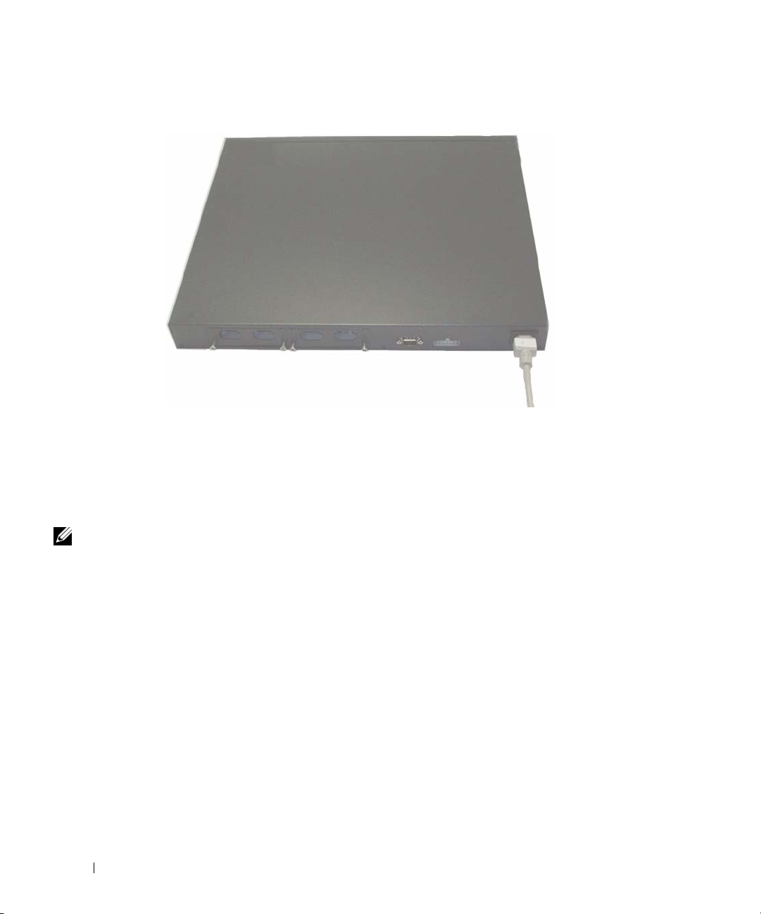
Figure 1-2. Connecting Power Cable
www.dell.com | support.dell.com
Assembling a Stack
You can stack PowerConnect 6200 series switches up to 12 switches high, supporting up to 576 front panel ports.
Create a stack by connecting adjacent units using the stacking ports on the left side of the switch rear. See
Figure 1-3.
NOTE: The switches must be turned off as they are added to a stack.
1
Install a separately purchased stacking module in rear "Bay 1" in each of the switches to be stacked.
2
Use the cables supplied with the stacking modules to connect from one switch to the next until all switches
are connected in a ring.
3
Make sure that the last stacking cable is connected from the last switch to the first switch to create a loop.
4
If necessary, use a separately purchased three-meter stacking cable to connect the switches.
8 Getting Started Guide

Figure 1-3. Connecting a Stack of Switches
NOTE: Long cable not shown in Figure 1-3.
The resulting ring topology allows the entire stack to function as a single switch with
capabilities.
Getting Started Guide 9
resilient fail-over

Starting and Configuring the Switch
After completing all external connections, connect a terminal to a switch to configure the switch or stack.
Additional advanced functions are described in the
NOTE: Read the release notes for this product before proceeding. You can download the release notes from
the Dell Support website at support.dell.com.
NOTE: We recommend that you obtain the most recent version of the user documentation from the Dell Support
website at support.dell.com.
User's Guide
Connecting the Terminal to the Switch
www.dell.com | support.dell.com
To monitor and configure the switch via serial console, use the console port on the rear of the switch to connect
it to a terminal desktop system running terminal emulation software. The console port connector is a male DB-9
connector, implemented as a data terminal equipment (DTE) connector.
The following is required to use the console port:
• VT100-compatible terminal or a desktop or a portable system with a serial port, running VT100 terminal
emulation software.
• An RS-232 crossover cable with a female DB-9 connector for the console port and the appropriate
connector for the terminal.
Perform the following tasks to connect a terminal to the switch console port:
NOTE: If you are installing a stack of switches, you need to assemble and cable the stack before powering up
and configuring the stack.
Connect an RS-232 crossover cable to the terminal running VT100 terminal emulation software.
1
2
Configure the terminal emulation software as follows:
a
Select the appropriate serial port (serial port 1 or serial port 2) to connect to the console.
b
Set the data rate to 9600 baud.
c
Set the data format to 8 data bits, 1 stop bit, and no parity.
d
Set the flow control to none.
e
Set the terminal emulation mode to
f
Select Terminal keys for Function, Arrow, and Ctrl keys. Make sure that the setting is for Terminal keys
(not Microsoft
®
Windows® keys).
VT100
.
located on your
User Documentation
CD.
NOTE: When using HyperTerminal with Microsoft Windows 2000, make sure that you have Windows 2000 Service Pack
2 or later installed. With Windows 2000 Service Pack 2, the arrow keys function properly in HyperTerminal's VT100
emulation. Go to www.microsoft.com for more information on Windows 2000 service packs.
10 Getting Started Guide

3
Connect the female connector of the RS-232 crossover cable directly to the switch console port, and
tighten the captive retaining bolts. The PowerConnect 6200 series console ports are located on the rear
panel as shown in Figure 1-4.
NOTE: If you are installing a stack of switches, connect the terminal to the Master Switch. This switch will light the
Master Switch LED, the top left LED in the array on the front panel. When a stack is powered up for the first time, the
switches elect the Master Switch, which may occupy any location in the stack. If you connect the terminal to a member
switch, you will not be able to use the CLI.
Figure 1-4. Connecting to the Console Port
Booting the Switch
1
Make sure that the switch console port is connected to a VT100 terminal or VT100 terminal emulator via
the RS-232 cable.
2
Locate an AC power receptacle.
3
Deactivate the AC power receptacle.
4
Connect the switch to the AC receptacle.
5
Activate the AC power receptacle.
When the power is turned on with the local terminal already connected, the switch goes through a power-on selftest (POST). POST runs every time the switch is initialized and checks hardware components to determine if
the switch is fully operational before completely booting. If POST detects a critical problem, the program flow
stops. If POST passes successfully, valid firmware is loaded into RAM. POST messages are displayed on the
terminal and indicate test success or failure. The boot process runs for approximately 60 seconds.
Getting Started Guide 11

Initial Configuration
NOTE: The initial simple configuration procedure is based on the following assumptions:
• The PowerConnect switch was never configured before and is in the same state as when you received it.
• The PowerConnect switch booted successfully.
• The console connection was established and the Dell Easy Setup Wizard prompt appears on the screen
of a VT100 terminal or terminal equivalent.
The initial switch configuration is performed through the console port. After the initial configuration, you can
manage the switch either from the already-connected console port or remotely through an interface defined
during the initial configuration.
NOTE: The switch is not configured with a default user name and password.
www.dell.com | support.dell.com
NOTE: All of the settings below are necessary to allow the remote management of the switch through Telnet
(Telnet client) or HTTP (Web browser).
Before setting up the initial configuration of the switch, obtain the following information from your network
administrator:
• The IP address to be assigned to the management VLAN through which the switch is managed.
• The IP subnet mask for the network.
• The IP address of the management VLAN default gateway for configuring the default route.
Initial Configuration Procedure
You can perform the initial configuration using the Dell Easy Setup Wizard, or by using the Command Line
Interface (CLI). The Setup Wizard automatically starts when the switch configuration file is empty. You can exit
the wizard at any point by entering [ctrl+z], but all configuration settings specified will be discarded (the switch
will use the default values). For more information on CLI initial configuration see the
shows how to use the Setup Wizard for initial switch configuration. The wizard sets up the following
configuration on the switch:
• Establishes the initial privileged user account with a valid password. The wizard configures
one privileged user account during the setup.
• Enables CLI login and HTTP access to use the local authentication setting only.
• Sets up the IP address for the management VLAN.
• Sets up the SNMP community string to be used by the SNMP manager at a given IP address.
You may choose to skip this step if SNMP management is not used for this switch.
• Allows you to specify the management server IP or permit management access from all IP addresses.
• Configures the default gateway IP address.
User Guide
. This guide
12 Getting Started Guide

Example Session
This section describes an Easy Setup Wizard session. The following values are used by the example session:
• IP address for the management VLAN is 192.168.1.100:255.255.255.0.
admin
• The user name is
, and password is
• The network management system IP address is
• The default gateway is 192.168.1.1.
• The SNMP community string to be used is
The setup wizard configures the initial values as defined above. After you complete the wizard, the switch
is configured as follows:
• SNMPv1/2c is enabled and the community string is set up as defined above. SNMPv3 is disabled
by default.
• The admin user account is set up as defined.
• A network management system is configured. From this management station, you can access the
SNMP, HTTP, and CLI interfaces. You may also choose to allow all IP addresses to access these
management interfaces by choosing the (0.0.0.0) IP address.
• An IP address is configured for the default management VLAN (1).
• A default gateway address is configured.
NOTE: In the example below, the possible user options are enclosed in [ ]. Also, where possible, the default value is
provided in { }. If you press <Enter> with no options defined, the default value is accepted. Help text is in parentheses.
The following example contains the sequence of prompts and responses associated with running an example
Dell Easy Setup Wizard session, using the input values listed above.
After the switch completes the POST and is booted, the following dialog appears:
Welcome to Dell Easy Setup Wizard
admin123.
192.168.1.10
.
Dell_Network_Manager
.
The setup wizard guides you through the initial switch configuration, and
gets you up and running as quickly as possible. You can skip the setup
wizard, and enter CLI mode to manually configure the switch. You must
respond to the next question to run the setup wizard within 60 seconds,
otherwise the system will continue with normal operation using the default
system configuration. Note: You can exit the setup wizard at any point by
entering [ctrl+z].
Would you like to run the setup wizard (you must answer this question within
60 seconds)? [Y/N] y<Enter>
Getting Started Guide 13

Step 1:
The system is not configured for SNMP management by default. To manage the
switch using SNMP (required for Dell Open Manage Network Manager) you can:
o Set up the initial SNMP version 1 & 2 now.
o Return later and set up other SNMP accounts. (For more information
on setting up an SNMP version 3 account, see the user documentation).
Would you like to configure the SNMP management interface now? [Y/N]
y<Enter>
To configure the SNMP management account you must specify the management
system IP address and the "community string" or password that the particular
www.dell.com | support.dell.com
management system uses to access the switch. The wizard automatically
assigns the highest access level [Privilege Level 15] to this account. You
can use Dell Open Manage Network Manager or other management interfaces to
change this setting and to add additional management systems later. For more
information on adding management systems, see the User’s Guide.
To add a management station:
Please enter the SNMP community string to be used {Dell_Network_Manager}:
Dell_Network_Manager<Enter>
NOTE: If it is configured, the default access level is set to the highest available access for the SNMP management
interface. Initially only SNMPv1/2c will be activated. SNMPv3 is disabled until you return to configure security access
for SNMPv3 (e.g. engine ID, view, etc.).
Please enter the IP address of the Management System (A.B.C.D) or wildcard
(0.0.0.0) to manage from any Management Station {0.0.0.0}:
192.168.1.10<Enter>
Step 2:
Now we need to configure your initial privilege (Level 15) user account.
This account is used to login to the CLI and Web interface. You may set up
other accounts and change privilege levels later. For more information on
setting up user accounts and changing privilege levels, see the User’s
Guide.
To set up a user account:
Please enter the user name {admin}: admin<Enter>
Please enter the user password: ********<Enter>
Please reenter the user password: ********<Enter>
NOTE: If the first and second password entries are not identical, the user is prompted until they are.
NOTE: You can create additional user accounts after completing the Easy Setup Wizard. See the User’s Guide
for more information.
14 Getting Started Guide

Step 3:
Next, an IP address is set up. The IP address is defined on the default VLAN
(VLAN #1), of which all ports are members. This is the IP address you use to
access the CLI, Web interface, or SNMP interface for the switch.
To set up an IP address:
Please enter the IP address of the device (A.B.C.D):
192.168.1.100<Enter>
Please enter the IP subnet mask (A.B.C.D or /nn):
255.255.255.0<Enter>
Step 4:
Finally, set up the gateway. Please enter the IP address of the gateway from
which this network is reachable (e.g. 192.168.1.1): 192.168.1.1<Enter>
This is the configuration information that has been collected:
SNMP Interface = "Dell_Network_Manager"@192.168.1.10
User Account set up = admin
Password = **********
Management IP address = 192.168.1.100:255.255.255.0
Gateway = 192.168.1.1
Step 5:
If the information is correct, please select (Y) to save the configuration,
and copy to the start-up configuration file. If the information is
incorrect, select (N) to discard configuration and restart the wizard: [Y/N]
y<Enter>
Thank you for using the Dell Easy Setup Wizard. You will now enter CLI mode.
Getting Started Guide 15

Managing a Stack
Master and Member Switches
A stack of switches can be managed as a single entity when connected together. The stack can be managed
from a web-based interface, an SNMP management station, or a CLI. When a stack is created, one switch
automatically becomes the master switch. You can manually allocate an IP address to the master switch using the
console, or let DHCP do so automatically. Afterwards, you can manage the entire stack through the IP address of
the Master Switch. The Master Switch detects and reconfigures the ports with minimal operational impact in
the event of:
www.dell.com | support.dell.com
• Switch failure
• Inter-switch stacking link failure
• Switch insertion
• Switch removal
If the Master Switch goes off line, any of the Member Switches in the stack can replace it. The system will elect
a new Master Switch and reconfigure the System Configuration for the stack.
Stack Startup
Topology Discovery
When a stack is formed, a topology discovery process builds up a database that contains information about all of
the switches in the stack, including the Firmware Version, Hardware Version, Management Preference, Switch
MAC Address, and Switch Serial Number. You can use the command line interface or the Web interface to view
this information.
See the CLI Reference Manual and the User’s Guide for assistance with the CLI and Web interface, respectively.
Auto Stack ID Assignment
During the stack formation process, every switch is assigned a Stack ID. Once Stack ID assignment is complete,
each switch saves its Stack ID into the nonvolatile FLASH memory. You can use the CLI or the Web interface
to view the stack IDs.
Firmware Version Checking
Following Stack ID assignment, the Master Switch performs a consistency check to make sure that all switches
in the stack are running the same firmware version.
If the switch software versions do not match, then the ports on the member switch will not become valid for
operation. This condition is known as the Suspended Stacking Mode. You can then synchronize the firmware
on the member switch with the firmware that is running on the Master Switch.
16 Getting Started Guide

System Initialization
If the Master Switch determines during the firmware version consistency check that all switches are running
the same version of firmware, the switch will be initialized for Stacking Mode.
System Initialization for Normal Stacking Mode
The Master Switch will initialize the stack using the last saved system configuration file. For those switches
that do not have a configuration file, the system will apply default settings to those switches.
If the configuration file is corrupted, the Master Switch will initialize the stack and set it to the Factory Default
Configuration.
You can save the configuration file. The Master Switch will automatically distribute the configuration file to
the member switches. If the Master Switch later becomes unavailable, a Member Switch can become the new
Master Switch and apply the configuration file that was saved on the original Master Switch.
System Initialization for Suspended Stacking Mode
After system initialization is complete, the Master Switch will enter Suspended Stacking Mode if the firmware
versions of the stack are inconsistent. In this mode, only the Master Switch is initialized with configuration file
information. None of the member switches are initialized. This forces all member switches to remain in nonoperational mode.
CLI/ Telnet/ Web Interface
You can use the CLI / WEB / SNMP to synchronize the firmware that is stored in the Master Switch to a member
switch.
Insertion and Removal of Switches
You can insert and remove switches to/from the current stack without cycling the power. The entire network may
be affected when a topology change occurs, as a stack reconfiguration will take place. A new Master Switch will
not be re-elected, unless the Master Switch was removed from the stack. Stack reconfiguration takes a maximum
of two minutes in a stack of twelve switches, less time for smaller stacks.
Operating as Standalone Switch
If a switch cannot detect a stacking partner on a port enabled for stacking, the switch will operate as a standalone
switch. If a stacking partner is detected, the switch will always operate in stacking mode.
Stack ID Renumbering
You can manually assign Stack IDs to a switch. A switch can only be assigned a Stack ID that has not already
been assigned to another switch in the stack. Any configuration information that was saved for the new Stack ID
is applied to the switch that is taking that Stack ID.
Getting Started Guide 17

User Controls
Use the following CLI commands to control this feature. See the
of each command.
movemanagement
reload
member
set description
switch priority
www.dell.com | support.dell.com
switch renumber
stacking
show stack-port
show stack-port counters
show stack-port diag
show switch
show supported switchtype
CLI Reference Guide
for details on the syntax
18 Getting Started Guide
Front Panels and LEDs
This appendix describes the front panels and LEDs of the Dell PowerConnect PC6224, PC6248, PC6224P,
PC6248P, and PC6224F systems.
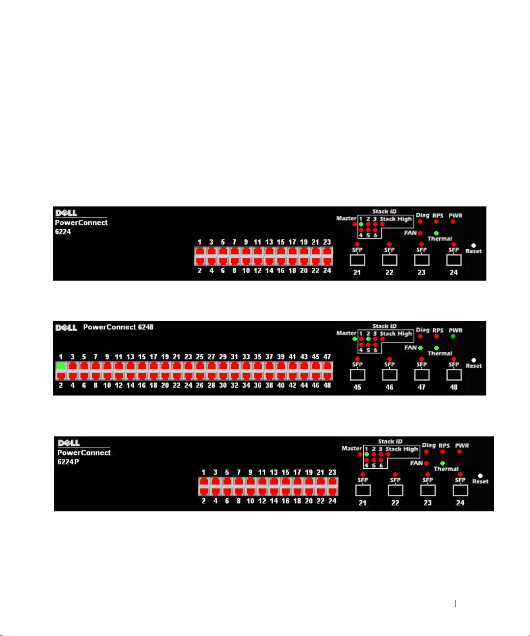
Front Panels
The front panels of the PowerConnect 6200 series systems are shown in the figures below.
Figure 1-1. PC 6224
Figure 1-2. PC 6248
Figure 1-3. PC 6224P
Getting Started Guide 19

Figure 1-4. PC 6248P
Figure 1-5. PC 6224F
www.dell.com | support.dell.com
LEDs
The following sections list the LEDs.
Systems LEDs
Table 1-1. System LEDs
LED State
Fan Status
Power Supply Status
Redundant Power Supply
Diagnostic
Temperature
• Green: All Fans are operating correctly
• Red: One or more fans have failed
• Green: PS operating correctly
• Red: PS failure
• Green: Redundant supply present and operating
correctly
• Red: Redundant supply present and failed
• Off: Redundant supply is not present
• Blinking Green: Diagnostics in progress
• Solid Green: Diagnostics completed successfully
• Red: Diagnostics failed
• Green: System temperature is below threshold limit
• Red: System temperature is above threshold limit
20 Getting Started Guide

RJ-45 LEDs (PoE)
The RJ-45 ports will have two integrated LEDs (One bi-color and one single color).
Table 1-2. RJ-45 LEDs (PoE)
LED State
Left - Single color: Port link/activity
Right (POE Model) - Dual color:
• Green: Link at 10/100/1000 Mbps
• Solid: Link but no activity
• Blinking: Link with activity
• Off: No Link
• Green: The port detects power device (PD) and
complies with the condition of the normal load
• Solid Amber: Overload or short of terminal port
or external forced voltage feeds into the port
• Blinking Amber: The total aggregated power
exceeds predefined power budget.
• Off: No PD, no power feeding
XFP LED
Table 1-3. XFP LED
LED State
Single color:
• Green Solid: Link
• Green Blinking: Activity
• Off: No Link
SFP LED
Table 1-4. SFP LED
LED State
Single color:
• Green Solid: Link
• Green Blinking: Activity
• Off: No Link
Getting Started Guide 21

www.dell.com | support.dell.com
22 Getting Started Guide

Dell™ PowerConnect™
6200 系列可堆叠交换机
使用入门指南
型号:
PC6224, PC6248, PC6224P, PC6248P 和 PC6224F
www.dell.com | support.dell.com

注、注意和警告
注:注表示可以帮助您更好地使用计算机的重要信息。
注意:注意表示可能会损坏硬件或导致数据丢失,并告诉您如何避免此类问题。
警告:警告表示可能会导致财产损失、人身伤害甚至死亡。
____________________
本说明文件中的信息如有更改,恕不另行通知。
© 2007 Dell Inc.
未经
Dell Inc.
本文中使用的商标:
的注册商标。
本文件中述及的其它商标和产品名称是指拥有相应商标和名称的公司或其制造的产品。
的其它商标和产品名称不拥有任何专有权。
型号:
PC6224, PC6248, PC6224P, PC6248P 和 PC6224F
2007 年 9
版权所有,翻印必究。
书面许可,严禁以任何形式进行复制。
Dell、DELL
月
P/N YC897
徽标和
PowerConnect 是 Dell Inc.
修订版
A02
的商标;
Microsoft 和 Windows 是 Microsoft Corporation
Dell Inc.
对本公司的商标和产品名称之外

目录
1 安装
现场准备 . . . . . . . . . . . . . . . . . . . . . . . . . . . . . . . . .
打开交换机包装
包装箱物品
打开包装步骤
安装交换机
在机架中安装
安装为自立式交换机
将交换机连接至终端
将交换机连接至电源设备
组装堆叠
. . . . . . . . . . . . . . . . . . . . . . . . . . . . .
. . . . . . . . . . . . . . . . . . . . . . . . . . . . . 27
. . . . . . . . . . . . . . . . . . . . . . . . . . . . 28
. . . . . . . . . . . . . . . . . . . . . . . . . . . . . . . .
. . . . . . . . . . . . . . . . . . . . . . . . . . . . 28
. . . . . . . . . . . . . . . . . . . . . . . . 29
. . . . . . . . . . . . . . . . . . . . . . . . . . .
. . . . . . . . . . . . . . . . . . . . . . . .
. . . . . . . . . . . . . . . . . . . . . . . . . . . . . . . . .
2 启动和配置交换机
将终端连接至交换机 . . . . . . . . . . . . . . . . . . . . . . . . . . .
引导交换机
初始配置
. . . . . . . . . . . . . . . . . . . . . . . . . . . . . . . .
. . . . . . . . . . . . . . . . . . . . . . . . . . . . . . . . .
初始配置过程
示例会话
. . . . . . . . . . . . . . . . . . . . . . . . . . . . 34
. . . . . . . . . . . . . . . . . . . . . . . . . . . . . . . 35
27
27
28
29
29
30
32
33
34
目录 25

3 管理堆叠
主交换机和成员交换机 . . . . . . . . . . . . . . . . . . . . . . . . .
堆叠启动
CLI
用户控件
. . . . . . . . . . . . . . . . . . . . . . . . . . . . . . . .
拓扑搜索
自动堆叠 ID 分配
检查固件版本
系统初始化
/远程登录/
插入和卸下交换机
作为独立交换机运行
堆叠 ID 重新编号
. . . . . . . . . . . . . . . . . . . . . . . . . . . . . . 39
. . . . . . . . . . . . . . . . . . . . . . . . . . 39
. . . . . . . . . . . . . . . . . . . . . . . . . . . . 39
. . . . . . . . . . . . . . . . . . . . . . . . . . . . . 39
. . . . . . . . . . . . . . . . . . . . . . .
界面
Web
. . . . . . . . . . . . . . . . . . . . . . . . . 40
. . . . . . . . . . . . . . . . . . . . . . . . 40
. . . . . . . . . . . . . . . . . . . . . . . . . . 40
. . . . . . . . . . . . . . . . . . . . . . . . . . . . . . . .
4 前面板和 LED
前面板 . . . . . . . . . . . . . . . . . . . . . . . . . . . . . . . . . .
. . . . . . . . . . . . . . . . . . . . . . . . . . . . . . . . . . .
LED
系统 LED
RJ-45 LED (PoE)
XFP LED
SFP LED
. . . . . . . . . . . . . . . . . . . . . . . . . . . . . . 44
. . . . . . . . . . . . . . . . . . . . . . . . . . . 45
. . . . . . . . . . . . . . . . . . . . . . . . . . . . . . . 45
. . . . . . . . . . . . . . . . . . . . . . . . . . . . . . . 45
39
39
40
41
43
44
26 目录

安装
本说明文件介绍有关安装、配置和操作
PC6248P
《用户指南》,或访问
更新信息。
和
PC6224F
系统的基本信息。有关详情,请参阅
Dell 支持 Web
Dell™ PowerConnect™ PC6224, PC6248, PC6224P,
CD
上的
站点
support.dell.com
User Documentation
以获取有关说明文件及固件的最新
现场准备
PowerConnect 6200
式摆放(放在平坦的平面上)。这些交换机可以作为独立的交换机使用。也可以将这些交换机
进行堆叠式安装,作为单个实体发挥作用并进行管理。
在安装一台或多台交换机之前,请确保选定的安装位置符合以下现场要求:
•
电源要求
•
空间要求
电源连接和通风的空间。
•
布线要求
电线和荧光照明装置)。
•
周围环境
非冷凝。
系列交换机既可安装在标准的
交换机应靠近易于插拔的电源插座(
—
正面及背面有足够的空间,以便操作员进行操作。请留出用于布线、
—
布线应远离电气干扰源(如无线电发送器、广播放大器、
—
交换机运行环境温度范围为
—
0 到 45C(32 到 113F
厘米(
48.26
100-250 VAC,50-60 Hz
英寸)机架中,也可以自立
19
),相对湿度最大为
)安装。
95%
,
打开交换机包装
包装箱物品
解开每个交换机的包装时,请确保其中包含以下物品:
一台
•
•
•
•
•
•
•
•
PowerConnect
一根交流电源线
一根
RS-232
一套用于机架安装的机架固定套件(两个安装支架、螺栓和锁紧螺帽)
一套用于自立式摆放交换机的自粘胶垫(包括四个垫)
User Documentation
使用入门指南
产品信息指南
交换机
电缆
CD
使用入门指南 27
打开包装步骤
注:在打开交换机的包装之前,先检查包装盒,如有任何损坏迹象,请立即报告。
将包装盒放在整洁的平坦表面上,然后剪断固定包装盒的所有包装带。
1
2
打开包装盒或取下包装盒盖。
3
从包装盒中小心取出交换机,然后将其放在稳定且整洁的表面上。
4
取出所有包装材料。
5
检查产品及附件是否出现损坏。
安装交换机
www.dell.com | support.dell.com
警告:请阅读《产品信息指南》中的安全信息,以及连接到该交换机或支持该交换机的其它交
换机的安全信息。
交流电源连接器和直流电源连接器均位于交换机的背面板上。建议连接冗余电源设备,
PoE
交换机连接
如非
在机架中安装
警告:请勿使用机架固定套件将交换机悬挂在台面或桌面下,或固定在墙壁上。
警告:断开交换机上的所有电缆,然后继续安装。取出交换机底部的所有自粘垫(如果已粘连)。
警告:在将多台交换机安装到机架中时,请自底向上安装交换机。
1
将附带的机架固定支架放在交换机的一侧,确保交换机上的固定孔与机架固定支架上的固
定孔对齐。图
PowerConnect RPS-600 或 PoE
显示了支架的安装位置。
1-1
交换机连接
PowerConnect EPS-470
。
图
固定支架
1-1.
2
将附带的螺栓插入机架固定孔,然后用螺丝刀将其拧紧。
3
在交换机的另一侧对机架固定支架重复此过程。
4
将交换机插入
定孔。
28 使用入门指南
48.26
厘米(
英寸)机架,确保交换机上的机架固定孔对准机架上的固
19
 Loading...