

Page 1

Dell Vostro 3350
Owner's Manual
Regulatory Model P13S
Regulatory Type P13S001
Page 2

Notes, Cautions, and Warnings
NOTE: A NOTE indicates important information that helps you make better use of your
computer.
CAUTION: A CAUTION indicates potential damage to hardware or loss of data if
instructions are not followed.
WARNING: A WARNING indicates a potential for property damage, personal injury, or
death.
Information in this publication is subject to change without notice.
© 2011 Dell Inc. All rights reserved.
Reproduction of these materials in any manner whatsoever without the written permission of Dell Inc. is
strictly forbidden.
Trademarks used in this text:
Latitude™, Latitude ON™, OptiPlex™, Vostro™, and Wi-Fi Catcher™ are trademarks of Dell Inc. Intel®,
Pentium®, Xeon®, Core™, Atom™, Centrino®, and Celeron® are registered trademarks or trademarks of Intel
Corporation in the U.S. and other countries. AMD® is a registered trademark and AMD Opteron™,
AMD Phenom™, AMD Sempron™, AMD Athlon™, ATI Radeon™, and ATI FirePro™ are trademarks of
Advanced Micro Devices, Inc. Microsoft®, Windows®, MS-DOS®, Windows Vista®, the Windows Vista start
button, and Office Outlook
United States and/or other countries.
(BDA) and licensed for use on discs and players. The
owned by the
registered trademark of Wireless Ethernet Compatibility Alliance, Inc.
Other trademarks and trade names may be used in this publication to refer to either the entities claiming the
marks and names or their products, Dell Inc. disclaims any proprietary interest in trademarks and trade
names other than its own.
Bluetooth
Dell™, the DELL logo, Dell Precision™, Precision ON™,ExpressCharge™,
®
are either trademarks or registered trademarks of Microsoft Corporation in the
®
SIG, Inc. and any use of such mark by Dell Inc. is under license.
Blu-ray Disc
™
is a trademark owned by the Blu-ray Disc Association
Bluetooth
®
word mark is a registered trademark and
Wi-Fi
®
is a
2011 – 06
Rev. A00
Page 3

Contents
Notes, Cautions, and Warnings..................................................................2
1 Working on Your Computer......................................................................7
Before Working Inside Your Computer.............................................................................7
Recommended Tools.........................................................................................................9
Turning Off Your Computer................................................................................................9
After Working Inside Your Computer................................................................................9
2 Battery........................................................................................................11
Removing The Battery.....................................................................................................11
Installing The Battery......................................................................................................12
3 Memory Card............................................................................................13
Removing The Memory Card...........................................................................................13
Installing The Memory Card............................................................................................14
4 Subscriber Identity Module (SIM) Card...............................................15
Removing The Phone Subscriber Identity Module (SIM)................................................15
Installing The Phone Subscriber Identity Module (SIM).................................................16
5 Access Panel............................................................................................17
Removing The Access Panel...........................................................................................17
Installing The Access Panel............................................................................................18
6 Memory......................................................................................................19
Removing The Memory Module......................................................................................19
Installing The Memory Module.......................................................................................20
7 Optical Drive..............................................................................................21
Removing The Optical Drive............................................................................................21
Page 4

Installing The Optical Drive.............................................................................................22
8 Hard Drive..................................................................................................23
Removing The Hard Drive................................................................................................23
Installing The Hard Drive.................................................................................................26
9 Wireless Local Area Network (WLAN) Card.......................................27
Removing Wireless Local Area Network (WLAN) Card..................................................27
Installing The Wireless Local Area Network (WLAN) Card............................................28
10 Keyboard..................................................................................................29
Removing The Keyboard.................................................................................................29
Installing The Keyboard..................................................................................................31
11 Wireless Wide Area Network (WWAN) Card...................................33
Removing The Wireless Wide Area Network (WWAN) Card.........................................33
Installing The Wireless Wide Area Network (WWAN) Card..........................................35
12 Palm Rest.................................................................................................37
Removing The Palm Rest.................................................................................................37
Installing The Palm Rest..................................................................................................44
13 Speaker....................................................................................................45
Removing The Speaker...................................................................................................45
Installing The Speaker.....................................................................................................46
14 Fingerprint Reader.................................................................................49
Removing The Fingerprint Reader...................................................................................49
Installing The Fingerprint Reader....................................................................................51
15 LED Board................................................................................................53
Removing The LED Board................................................................................................53
Installing The LED Board.................................................................................................54
Page 5

16 Power-Button Board..............................................................................55
Removing The Power-Button Board...............................................................................55
Installing The Power-Button Board................................................................................56
17 Quick Launch Button Board.................................................................57
Removing The Quick Launch Button Board....................................................................57
Installing The Quick Launch Button Board.....................................................................58
18 Coin-Cell Battery....................................................................................61
Removing The Coin-Cell Battery.....................................................................................61
Installing The Coin-Cell Battery.......................................................................................61
19 Heat Sink..................................................................................................63
Removing The Heat Sink.................................................................................................63
Installing The Heat Sink..................................................................................................64
20 Processor................................................................................................65
Removing The Processor................................................................................................65
Installing The Processor.................................................................................................66
21 Display Assembly...................................................................................69
Removing The Display Assembly....................................................................................69
Installing The Display Assembly.....................................................................................71
22 Display Bezel...........................................................................................73
Removing The Display Bezel...........................................................................................73
Installing The Display Bezel............................................................................................74
23 Camera.....................................................................................................75
Removing The Camera....................................................................................................75
Installing The Camera.....................................................................................................76
24 Display Panel..........................................................................................79
Removing The Display Panel...........................................................................................79
Page 6

Installing The Display Panel............................................................................................81
25 Display Brackets and Hinges...............................................................83
Removing Display Brackets And Hinges.........................................................................83
Installing The Display Brackets And Hinges...................................................................85
26 Display Cable..........................................................................................87
Removing The Display Cable...........................................................................................87
Installing The Display Cable............................................................................................88
27 System Board..........................................................................................89
Removing The System Board..........................................................................................89
Installing The System Board...........................................................................................91
28 Input/Output Board................................................................................93
Removing The Input/Output (I/O) Board..........................................................................93
Installing The Input/Output Board...................................................................................94
29 System Setup..........................................................................................95
System Setup Overview..................................................................................................95
System Setup Enter.........................................................................................................95
System Setup Screens....................................................................................................96
System Setup Options.....................................................................................................97
30 Diagnostics............................................................................................101
Device Status Lights......................................................................................................101
Battery Status Lights.....................................................................................................101
Diagnostic Beep Codes.................................................................................................101
31 Specifications.......................................................................................103
32 Contacting Dell.....................................................................................113
Contacting Dell..............................................................................................................113
Page 7

1
Working on Your Computer
Before Working Inside Your Computer
Use the following safety guidelines to help protect your computer from potential
damage and to help to ensure your personal safety. Unless otherwise noted,
each procedure included in this document assumes that the following
conditions exist:
• You have performed the steps in Working on Your Computer.
• You have read the safety information that shipped with your computer.
• A component can be replaced or--if purchased separately--installed by
performing the removal procedure in reverse order.
WARNING: Before working inside your computer, read the safety information that
shipped with your computer. For additional safety best practices information, see
the Regulatory Compliance Homepage at www.dell.com/regulatory_compliance.
CAUTION: Many repairs may only be done by a certified service technician. You
should only perform troubleshooting and simple repairs as authorized in your
product documentation, or as directed by the online or telephone service and
support team. Damage due to servicing that is not authorized by Dell is not covered
by your warranty. Read and follow the safety instructions that came with the
product.
CAUTION: To avoid electrostatic discharge, ground yourself by using a wrist
grounding strap or by periodically touching an unpainted metal surface, such as a
connector on the back of the computer.
CAUTION: Handle components and cards with care. Do not touch the components
or contacts on a card. Hold a card by its edges or by its metal mounting bracket.
Hold a component such as a processor by its edges, not by its pins.
7
Page 8

CAUTION: When you disconnect a cable, pull on its connector or on its pull-tab, not
on the cable itself. Some cables have connectors with locking tabs; if you are
disconnecting this type of cable, press in on the locking tabs before you disconnect
the cable. As you pull connectors apart, keep them evenly aligned to avoid bending
any connector pins. Also, before you connect a cable, ensure that both connectors
are correctly oriented and aligned.
NOTE: The color of your computer and certain components may appear differently
than shown in this document.
To avoid damaging your computer, perform the following steps before you begin
working inside the computer.
1. Ensure that your work surface is flat and clean to prevent the computer
cover from being scratched.
2. Turn off your computer (see
Turning Off Your Computer
).
3. If the computer is connected to a docking device (docked) such as the
optional Media Base or Battery Slice, undock it.
CAUTION: To disconnect a network cable, first unplug the cable from your
computer and then unplug the cable from the network device.
4. Disconnect all network cables from the computer.
5. Disconnect your computer and all attached devices from their electrical
outlets.
6. Close the display and turn the computer upside-down on a flat work
surface.
NOTE: To avoid damaging the system board, you must remove the main battery
before you service the computer.
7. Remove the main battery.
8. Turn the computer top-side up.
9. Open the display.
10. Press the power button to ground the system board.
CAUTION: To guard against electrical shock, always unplug your computer from the
electrical outlet before opening the display.
CAUTION: Before touching anything inside your computer, ground yourself by
touching an unpainted metal surface, such as the metal at the back of the
computer. While you work, periodically touch an unpainted metal surface to
dissipate static electricity, which could harm internal components.
8
Page 9
11. Remove any installed ExpressCards or Smart Cards from the appropriate
slots.
Recommended Tools
The procedures in this document may require the following tools:
• Small flat-blade screwdriver
• #0 Phillips screwdriver
• #1 Phillips screwdriver
• Small plastic scribe
• Flash BIOS update program CD
Turning Off Your Computer
CAUTION: To avoid losing data, save and close all open files and exit all open
programs before you turn off your computer.
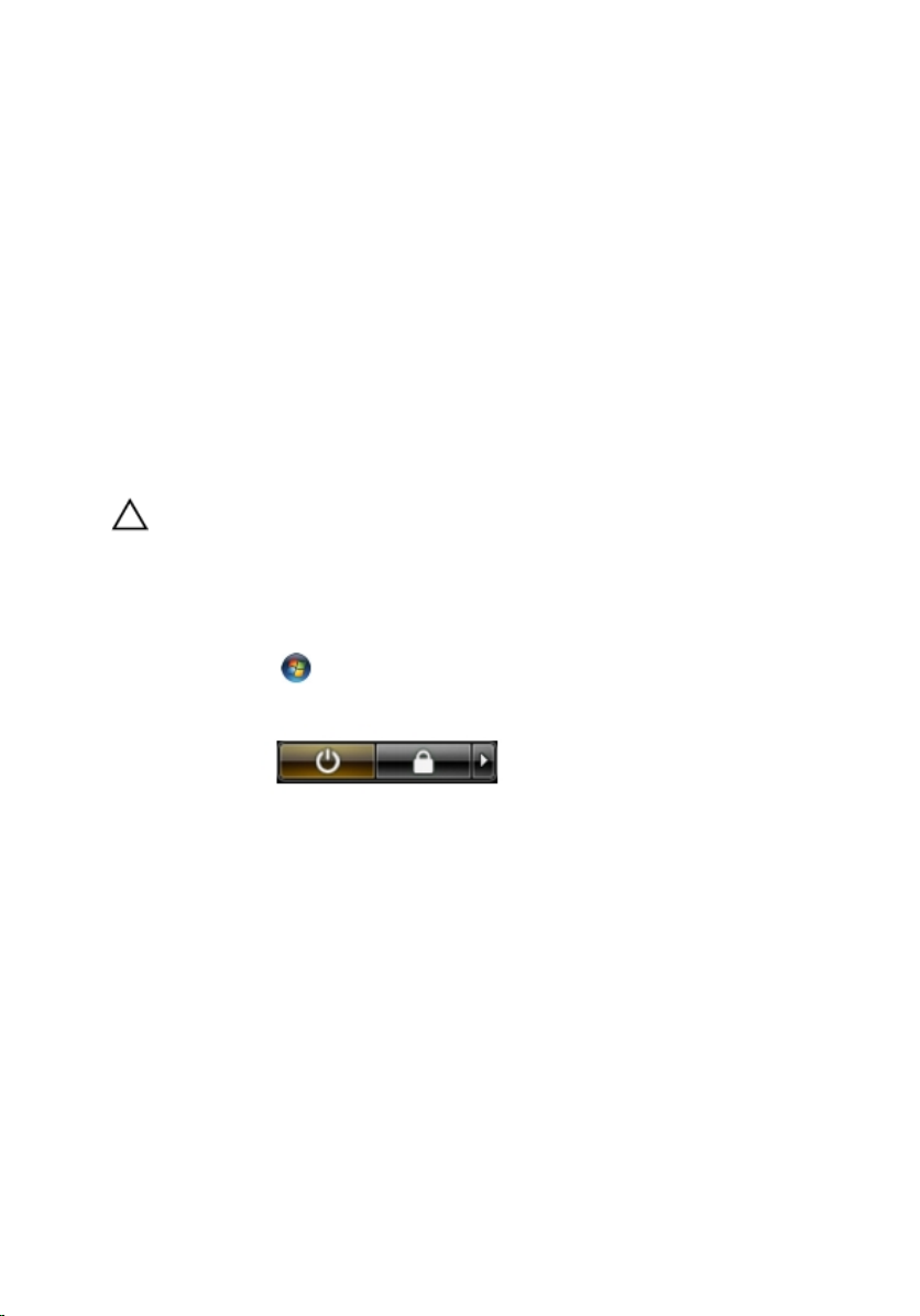
1. Shut down the operating system:
• In Windows Vista :
Click Start
Start menu as shown below, and then click Shut Down.
• In Windows XP:
Click Start → Turn Off Computer → Turn Off . The computer turns off
after the operating system shutdown process is complete.
2. Ensure that the computer and all attached devices are turned off. If your
computer and attached devices did not automatically turn off when you
shut down your operating system, press and hold the power button for
about 4 seconds to turn them off.
, then click the arrow in the lower-right corner of the
After Working Inside Your Computer
After you complete any replacement procedure, ensure you connect any
external devices, cards, and cables before turning on your computer.
9
Page 10

CAUTION: To avoid damage to the computer, use only the battery designed for this
particular Dell computer. Do not use batteries designed for other Dell computers.
1. Connect any external devices, such as a port replicator, battery slice, or
media base, and replace any cards, such as an ExpressCard.
2. Connect any telephone or network cables to your computer.
CAUTION: To connect a network cable, first plug the cable into the network device
and then plug it into the computer.
3. Replace the battery.
4. Connect your computer and all attached devices to their electrical outlets.
5. Turn on your computer.
10
Page 11
Battery
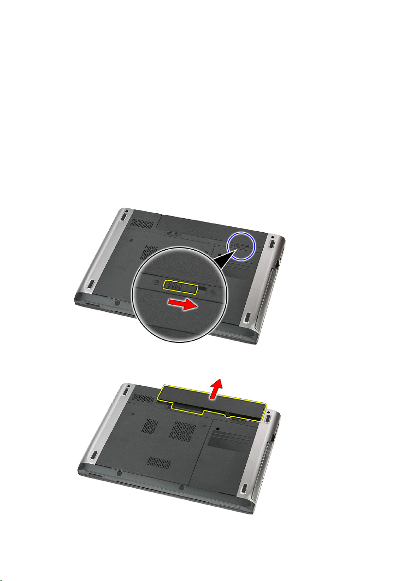
Removing The Battery
2
1. Follow the procedures in
2. Slide the release latches to unlock the battery.
3. Slide the battery and remove it from the computer.
Before Working On Your Computer
.
11
Page 12

Installing The Battery
1. Slide the battery into its slot until it clicks into place.
2. Follow the procedures in
After Working Inside Your Computer
.
12
Page 13

Memory Card
Removing The Memory Card
3
1. Follow the procedures in
2. Press in on the memory card to release it from the computer.
3. Slide the memory card out of the computer.
Before Working On Your Computer
.
13
Page 14

Installing The Memory Card
1. Push the memory card into the compartment until it snaps into place.
2. Follow the procedures in
After Working Inside Your Computer
.
14
Page 15
Subscriber Identity Module (SIM) Card
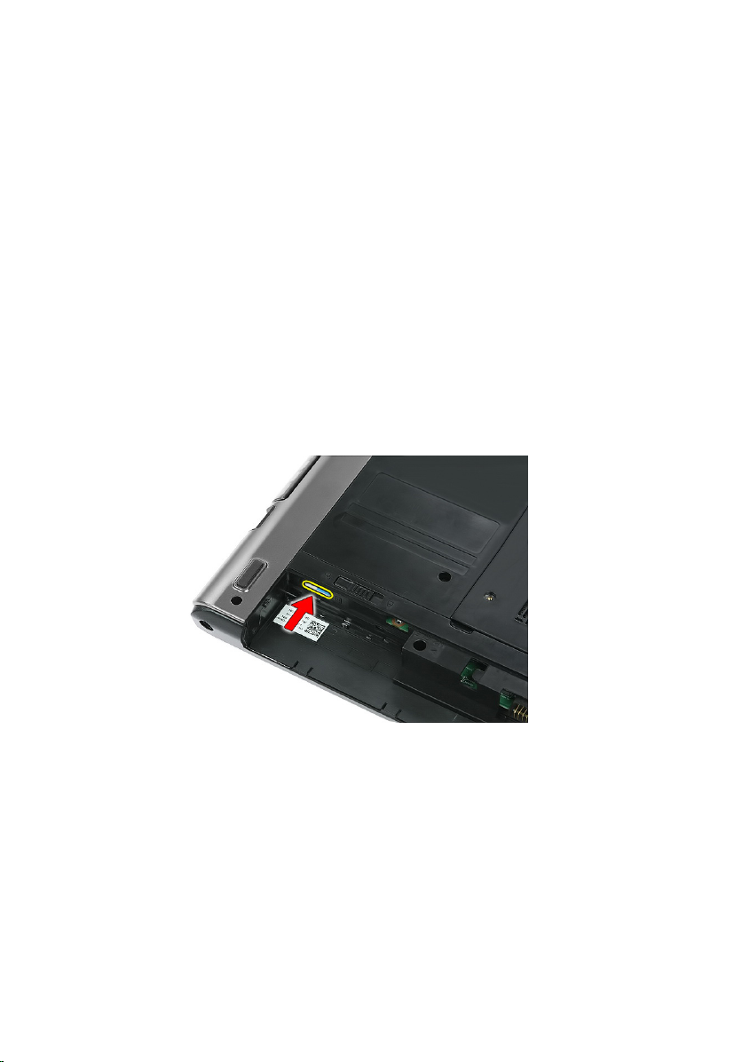
Removing The Phone Subscriber Identity Module (SIM)
4
1. Follow the procedures in
2. Remove the
3. Press in on the SIM card to release it from the computer.
4. Grasp the SIM card and pull out to release it from the computer.
battery
Before Working On Your Computer
.
.
15
Page 16

Installing The Phone Subscriber Identity Module (SIM)
1. Push the SIM card into the slot until it is fully engaged.
2. Install the
3. Follow the procedures in
battery
.
After Working Inside Your Computer
.
16
Page 17
Access Panel
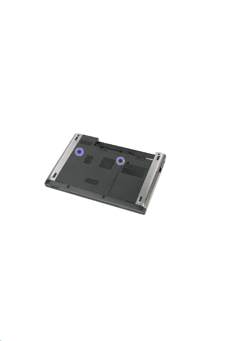
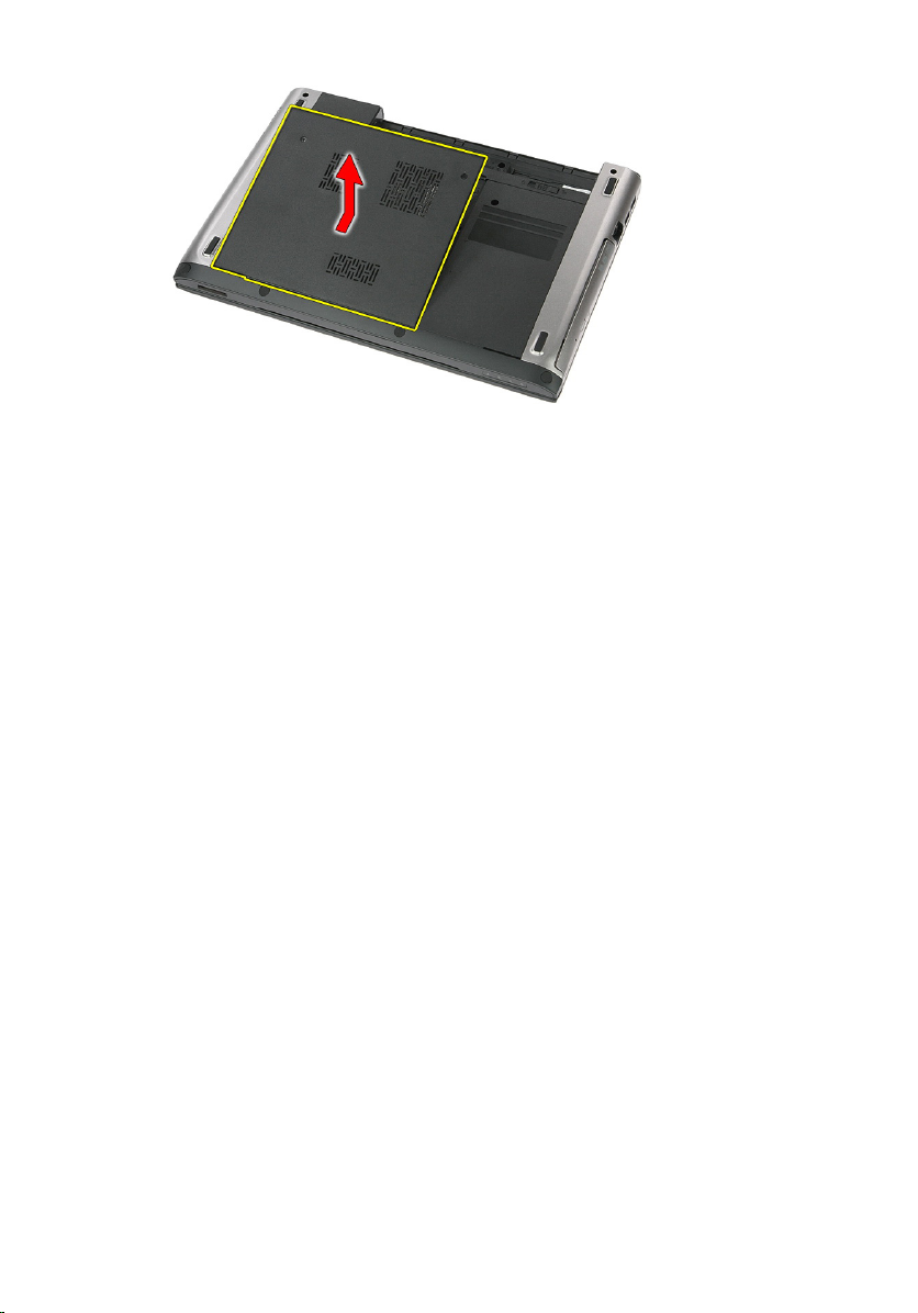
Removing The Access Panel
5
1. Follow the procedures in
2. Remove the
3. Remove the screws that secures the access panel to the base of the
computer.
4. Lift the access panel up at an angle and remove it from the computer.
battery
Before Working On Your Computer
.
.
17
Page 18
Installing The Access Panel
1. Tighten the screws to secure the access panel to the base of the computer.
2. Install the
3. Follow the procedures in
battery
.
After Working Inside Your Computer
.
18
Page 19
Memory
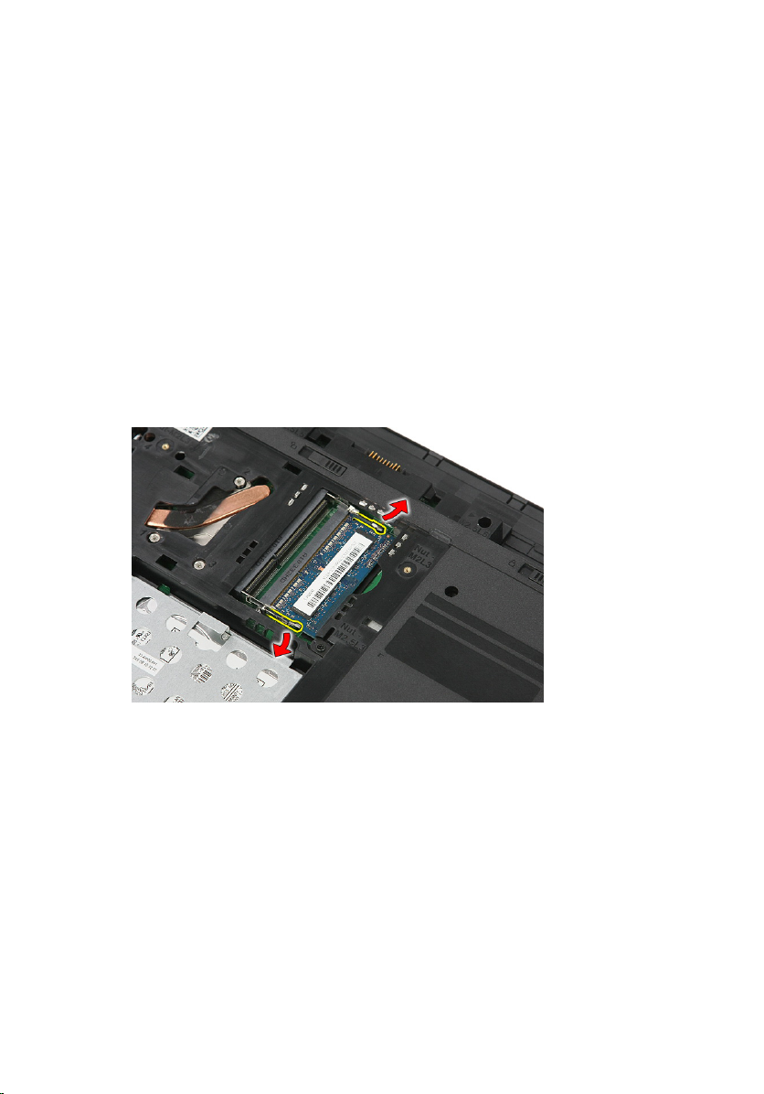
Removing The Memory Module
6
1. Follow the procedures in
2. Remove the
3. Remove the
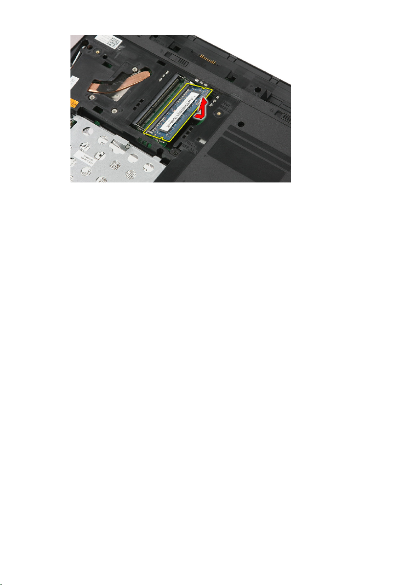
4. Pry the retention clips away from the memory module until it pops up.
5. Remove the memory module from its connector on the system board.
battery
access panel
Before Working On Your Computer
.
.
19
Page 20
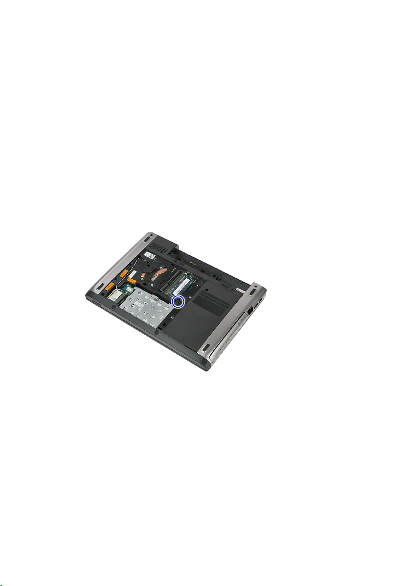
Installing The Memory Module
1. Insert and secure the memory module to the system board.
2. Install the
3. Install the
4. Follow the procedures in
access panel
battery
.
.
After Working Inside Your Computer
.
20
Page 21
Optical Drive
Removing The Optical Drive
7
1. Follow the procedures in
2. Remove the
3. Remove the
4. Remove the screw that secures the optical drive to the computer.
5. Use a screwdriver to pry the optical drive out of the computer.
battery
access panel
Before Working On Your Computer
.
.
.
21
Page 22
Installing The Optical Drive
1. Slide the optical drive into its compartment on the chassis.
2. Tighten the screw to secure the optical drive to the computer.
3. Install the
4. Install the
5. Follow the procedures in
access panel
battery
.
.
After Working Inside Your Computer
.
22
Page 23
Hard Drive
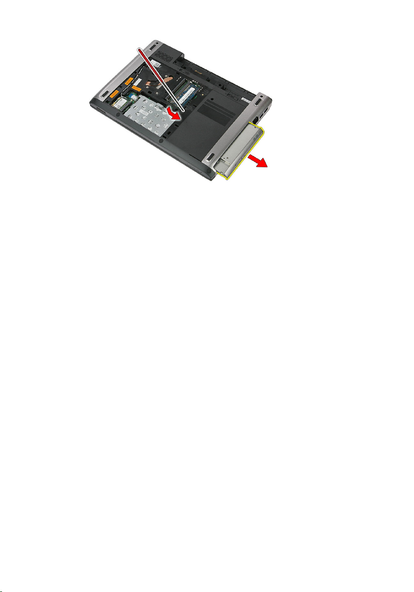
Removing The Hard Drive
8
1. Follow the procedures in
2. Remove the
3. Remove the
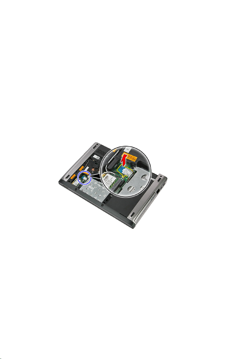
4. Open the clip that secures the hard-drive assembly to the computer.
5. Disconnect the hard-drive cable from the hard drive.
battery
access panel
Before Working On Your Computer
.
.
.
23
Page 24
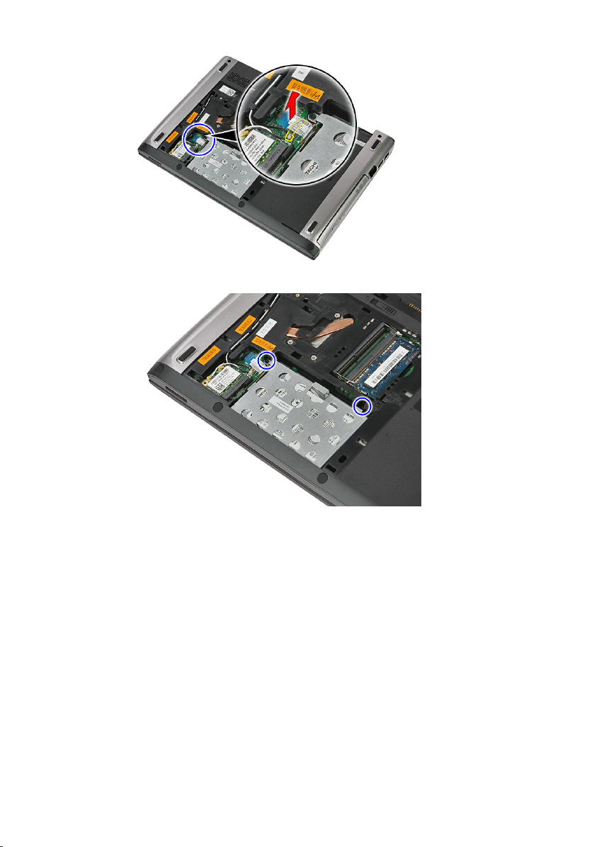
6. Remove the screws that secure the hard-drive assembly to the computer.
7. Lift the hard drive up at an angle from the system and remove it from the
computer.
24
Page 25
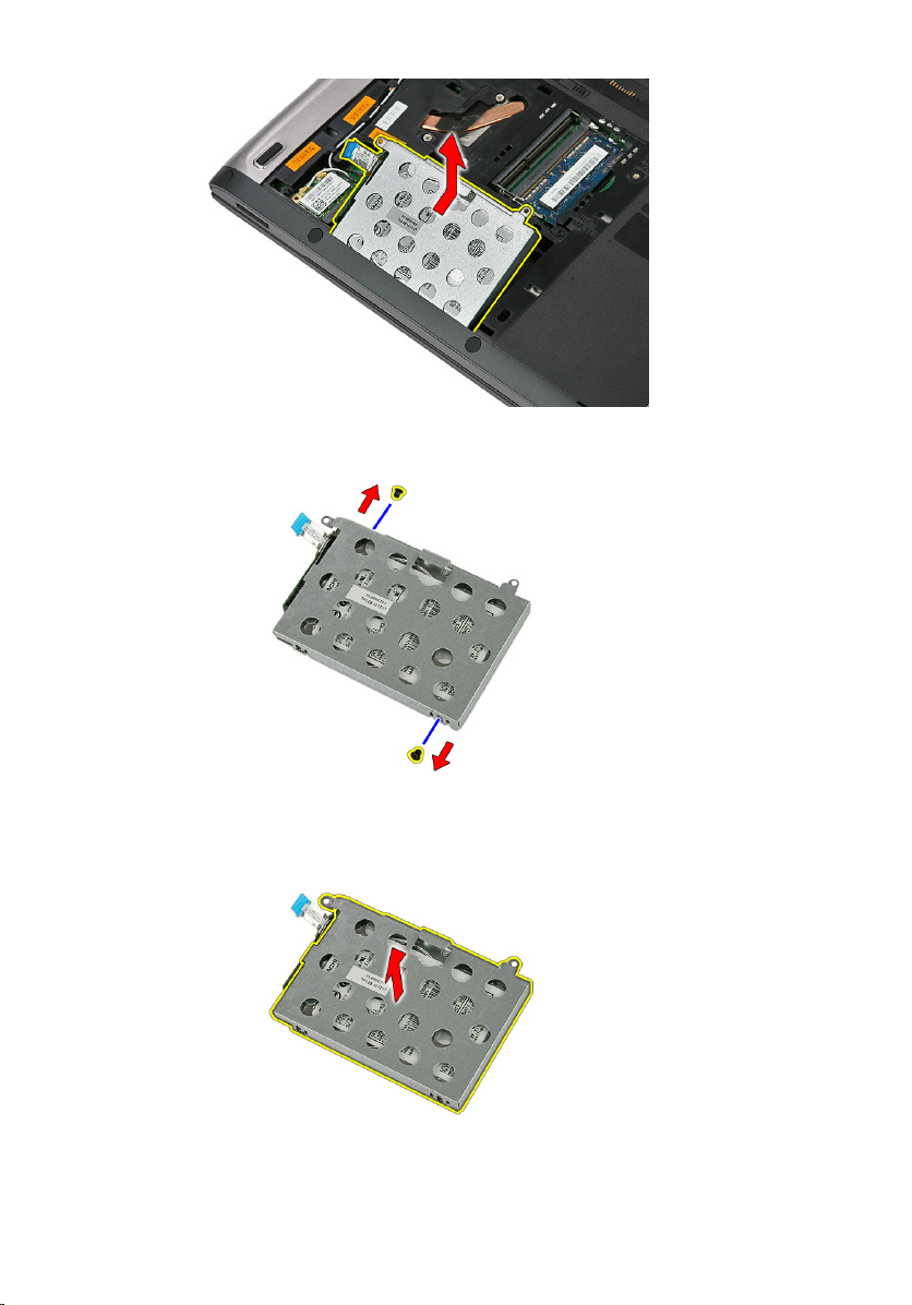
8. Remove the screws that secure the hard-drive bracket to the hard drive.
9. Lift the hard-drive bracket up and away from the hard drive.
25
Page 26
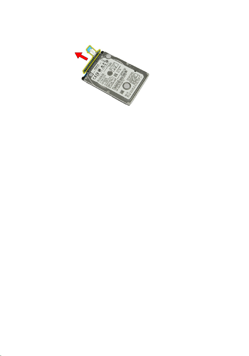
10. Remove the hard drive board from the hard drive.
Installing The Hard Drive
1. Install the screws to secure the hard drive board to the hard drive.
2. Place the hard drive in its compartment .
3. Replace the screws to secure the hard drive to the system.
4. Connect the hard drive cable to the system board.
5. Replace the hard drive cable securing clip.
6. Install the
7. Install the
8. Follow the procedures in
access panel
battery
.
.
After Working Inside Your Computer
.
26
Page 27
Wireless Local Area Network (WLAN) Card
Removing Wireless Local Area Network (WLAN) Card
9
1. Follow the procedures in
2. Remove the
3. Remove the access panel.
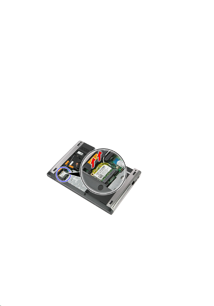
4. Disconnect the antenna cables from the WLAN card.
5. Use a scribe to pry the latch to release the WLAN card.
battery
Before Working On Your Computer
.
.
27
Page 28
6. Remove the WLAN card from the computer.
Installing The Wireless Local Area Network (WLAN) Card
1. Slide the WLAN card into its slot.
2. Connect the antenna cables according to the color code on the WLAN
card.
3. Install the
4. Install the
5. Follow the procedures in
28
access panel
battery
.
.
After Working Inside Your Computer
.
Page 29
Keyboard
Removing The Keyboard
10
1. Follow the procedures in
2. Remove the
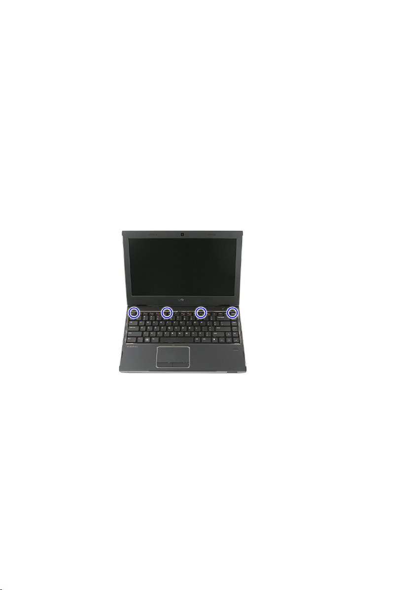
3. Using a small plastic scribe, release the four latches that secures the
keyboard to the computer.
4. Flip the keyboard over and lay it on the palm rest.
battery
Before Working On Your Computer
.
.
29
Page 30
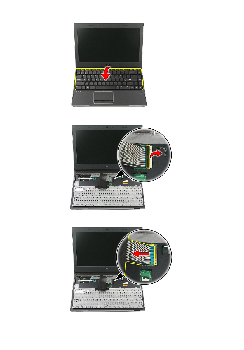
5. Open the clip to release the keyboard cable.
6. Disconnect the keyboard cable from its connector on the system board.
30
Page 31

7. If your computer comes with a backlit keyboard, disconnect the keyboard
backlight cable.
8. Remove the keyboard from the computer.
Installing The Keyboard
1. Connect the keyboard data cable to the system board.
2. Install the
3. Follow the procedures in
battery
.
After Working Inside Your Computer
.
31
Page 32

32
Page 33

Wireless Wide Area Network (WWAN) Card
Removing The Wireless Wide Area Network (WWAN) Card
11
1. Follow the procedures in
2. Remove the
3. Remove the
4. Open the power button board cable securing clip.
5. Disconnect the power button board cable.
battery
keyboard
Before Working On Your Computer
.
.
33
Page 34

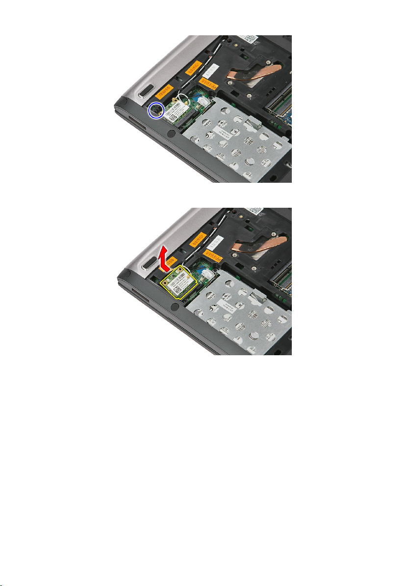
6. Disconnect the antenna cables from the WWAN card.
7. Use a scribe to pry the latch that secures the WWAN card.
34
Page 35

8. Remove the WWAN card from the computer.
Installing The Wireless Wide Area Network (WWAN) Card
1. Slide the Wireless Wide Area Network (WWAN) card into its slot.
2. Connect the antenna cables according to the color code on the WWAN
card.
3. Install the
4. Install the
5. Install the
6. Follow the procedures in
power button board cable
keyboard
battery
.
.
After Working Inside Your Computer
.
.
35
Page 36

36
Page 37

Palm Rest
Removing The Palm Rest
12
1. Follow the procedures in
2. Remove the
3. Remove the
4. Remove the
5. Remove the
6. Remove the
7. Remove the rubber from the bottom of the computer.
8. Remove the screws that secure the palm rest to the bottom of the
computer.
battery
memory card
access panel
hard drive
keyboard
Before Working On Your Computer
.
.
.
.
.
.
37
Page 38

9. Open the clip that secures the power-button board cable to the system
board.
10. Disconnect the power-button board cable from its connector on the system
board.
38
Page 39

11. Open the clip that secures the LED board cable to the system board.
12. Disconnect the LED board cable from its connector on the system board.
39
Page 40

13. Open the clip that secures the touchpad data cable to the system board.
14. Disconnect the touchpad data cable from its connector on the system
board.
15. Open the clip that secures the finger print reader cable to the system
board.
40
Page 41

16. Disconnect the finger print reader cable from its connector on the system
board.
17. Open the clip that secures the quick launch board cable to the system
board.
41
Page 42

18. Disconnect the quick launch board cable from its connector on the system
board.
19. Remove the screws that secure the palm rest to the front of the computer.
42
Page 43

20. Pry along the edges of the palm rest to release the palm rest.
21. Lift the palm rest up and away from the computer.
43
Page 44

Installing The Palm Rest
1. Starting from the right edge of the palm rest, press downwards on the
computer to engage the tabs.
2. Work your way around the edges and ensure the tabs are fully engaged.
3. Connect all cables to the system board.
4. Tighten the screws to secure the palm rest.
5. Tighten the screws on the bottom of the computer to secure the palm rest.
6. Install the
7. Install the
8. Install the
9. Install the
10. Install the
11. Follow the procedures in
keyboard
hard drive
.
.
access panel
memory card
battery
.
.
After Working Inside Your Computer
.
44
Page 45

Speaker
Removing The Speaker
13
1. Follow the procedures in
2. Remove the
3. Remove the
4. Remove the
5. Remove the
6. Remove the
7. Remove the
8. Disconnect the speaker cable from its connector on the system board.
battery
memory card
access panel
hard drive
keyboard
palm rest
Before Working on Your Computer
.
.
.
.
.
.
.
9. Release the speaker from its securing posts.
45
Page 46

10. Release the speaker cable from the routing channel.
11. Lift the speakers up and away from the computer.
Installing The Speaker
1. Install the speaker cable in the routing channel.
2. Install the speaker to its securing posts.
3. Connect the speaker cable.
4. Install the
5. Install the
6. Install the
7. Install the
8. Install the
palm rest
keyboard
hard drive
.
.
.
access panel
memory card
.
46
Page 47

9. Install the
10. Follow the procedures in
battery
.
After Working Inside Your Computer
.
47
Page 48

48
Page 49

Fingerprint Reader
Removing The Fingerprint Reader
14
1. Follow the procedures in
2. Remove the
3. Remove the
4. Remove the
5. Remove the
6. Remove the
7. Remove the
8. Release the fingerprint reader cable from the adhesive affixing it to the
palm rest.
battery
memory card
access panel
hard drive
keyboard
palm rest
Before Working On Your Computer
.
.
.
.
.
.
.
9. Remove the screw that secures the fingerprint reader bracket.
49
Page 50

10. Lift up the fingerprint reader bracket at an angle and remove it from the
computer.
11. Lift up the fingerprint reader board and remove.
50
Page 51

Installing The Fingerprint Reader
1. Install the fingerprint reader board and the bracket.
2. Tighten the screws that secure the fingerprint reader bracket.
3. Affix the finger print reader cable to the palm rest.
4. Install the
5. Install the
6. Install the
7. Install the
8. Install the
9. Install the
10. Follow the procedures in
palm rest
keyboard
.
.
hard drive
access panel
memory card
battery
.
.
.
After Working Inside Your Computer
.
51
Page 52

52
Page 53

LED Board
Removing The LED Board
15
1. Follow the procedures in
2. Remove the
3. Remove the
4. Remove the
5. Remove the
6. Remove the
7. Remove the
8. Peel open the tape that secures the LED board cable.
battery
memory card
access panel
hard drive
keyboard
palm rest
Before Working On Your Computer
.
.
.
.
.
.
.
9. Pry the latches that secure the LED board; then lift up and remove the LED
board from the computer.
53
Page 54

Installing The LED Board
1. Secure the latches to the LED board.
2. Affix the tape to secure the LED board cable.
3. Install the
4. Install the
5. Install the
6. Install the
7. Install the
8. Install the
9. Follow the procedures in
palm rest
keyboard
.
.
hard drive
access panel
memory card
battery
.
.
.
After Working Inside Your Computer
.
54
Page 55

Power-Button Board
Removing The Power-Button Board
16
1. Follow the procedures in
2. Remove the
3. Remove the
4. Remove the
5. Remove the
6. Remove the
7. Remove the
8. Remove the
9. Remove the screw that secures the power-button board.
battery
memory card
access panel
memory
hard drive
keyboard
palm rest
Before Working On Your Computer
.
.
.
.
.
.
.
.
10. Pry the latch to release the power-button board; then lift up and remove it
from the computer.
55
Page 56

Installing The Power-Button Board
1. Install the power-button board and tighten the screw.
2. Install the
3. Install the
4. Install the
5. Install the
6. Install the
7. Install the
8. Install the
9. Follow the procedures in
palm rest
keyboard
.
.
hard drive
memory
.
access panel
memory card
battery
.
.
.
After Working Inside Your Computer
.
56
Page 57

Quick Launch Button Board
Removing The Quick Launch Button Board
17
1. Follow the procedures in
2. Remove the
3. Remove the
4. Remove the
5. Remove the
6. Remove the
7. Remove the
8. Remove the
9. Release the quick launch button board cable from the adhesive affixing it to
the palm rest.
battery
memory card
access panel
memory
hard drive
keyboard
palm rest
Before Working On Your Computer
.
.
.
.
.
.
.
.
10. Remove the screw that secures the quick launch button board.
57
Page 58

11. Pry the latches to release the quick launch button board; then lift up and
remove it from the computer.
Installing The Quick Launch Button Board
1. Install the quick launch button board and tighten the screw.
2. Affix the quick launch button board cable to the palm rest.
3. Install the
4. Install the
5. Install the
6. Install the
7. Install the
8. Install the
palm rest
keyboard
.
.
hard drive
memory
.
access panel
memory card
.
.
58
Page 59

9. Install the
10. Follow the procedures in
battery
.
After Working Inside Your Computer
.
59
Page 60

60
Page 61

Coin-Cell Battery
Removing The Coin-Cell Battery
18
1. Follow the procedures in
2. Remove the
3. Remove the
4. Remove the
5. Remove the
6. Remove the
7. Remove the
8. Pry the tabs that secure the coin-cell battery to the system board.
battery
memory card
access panel
hard drive
keyboard
palm rest
Before Working on Your Computer
.
.
.
.
.
.
.
Installing The Coin-Cell Battery
1. Insert the coin-cell battery into the slot and press until it snaps into place.
2. Install the
3. Install the
palm rest
keyboard
.
.
61
Page 62

4. Install the
5. Install the
6. Install the
7. Install the
8. Follow the procedures in
hard drive
.
access panel
memory card
battery
.
After Working Inside Your Computer
.
62
Page 63

Heat Sink
Removing The Heat Sink
19
1. Follow the procedures in
2. Remove the
3. Remove the
4. Remove the
5. Remove the
6. Remove the
7. Remove the
8. Remove the
9. Remove the
10. Remove the
11. Remove the
12. Remove the
13. Remove the
14. Lift the heat sink and fan assembly up and away from the system board.
battery
memory card
access panel
memory
WLAN card
optical drive
hard drive
keyboard
WWAN card
palm rest
display assembly
system board
Before Working On Your Computer
.
.
.
.
.
.
.
.
.
.
.
.
.
63
Page 64

Installing The Heat Sink
1. Install the heat sink in the slot.
2. Install the
3. Install the
4. Install the
5. Install the
6. Install the
7. Install the
8. Install the
9. Install the
10. Install the
11. Install the
12. Install the
13. Install the
14. Follow the procedures in
system board
display assembly
palm rest
WWAN card
keyboard
.
.
.
hard drive
optical drive
WLAN card
memory
access panel
memory card
battery
.
.
.
.
.
.
After Working Inside Your Computer
.
.
64
Page 65

Processor
Removing The Processor
20
1. Follow the procedures in
2. Remove the
3. Remove the
4. Remove the
5. Remove the
6. Remove the
7. Remove the
8. Remove the
9. Remove the
10. Remove the
11. Remove the
12. Remove the
13. Remove the
14. Using a flat-blade screwdriver, rotate the processor cam lock in a counterclockwise direction.
battery
memory card
access panel
memory
WLAN card
optical drive
hard drive
keyboard
WWAN card
palm rest
display assembly
system board
Before Working On Your Computer
.
.
.
.
.
.
.
.
.
.
.
.
.
65
Page 66

15. Lift the processor up and away from the system board.
Installing The Processor
1. Insert the processor into the processor socket. Ensure the processor is
properly seated.
2. Tighten the cam lock in a clockwise direction.
3. Install the
4. Install the
5. Install the
6. Install the
7. Install the
8. Install the
system board
display assembly
palm rest
WWAN card
keyboard
.
.
.
hard drive
.
66
Page 67

9. Install the
10. Install the
11. Install the
12. Install the
13. Install the
14. Install the
15. Follow the procedures in
optical drive
WLAN card
memory
.
.
access panel
memory card
battery
.
.
.
.
After Working Inside Your Computer
.
67
Page 68

68
Page 69

Display Assembly
Removing The Display Assembly
21
1. Follow the procedures in
2. Remove the
3. Remove the
4. Remove the
5. Remove the
6. Remove the
7. Remove the
8. Remove the
9. Remove the
10. Disconnect the antenna cables from the routing channel.
battery
memory card
access panel
WLAN card
hard drive
keyboard
WWAN card
palm rest
Before Working On Your Computer
.
.
.
.
.
.
.
.
.
11. Pull out the antenna cables from the routing hole.
69
Page 70

12. Disconnect the display cable from the system board.
13. Release the WWAN cables from the routing channel.
70
Page 71

14. Remove the screws that secure the display assembly to the computer.
15. Lift the display assembly up from the computer, then forward and remove.
Installing The Display Assembly
1. Attach the display assembly to the base of the computer.
2. Tighten the screws to secure the display assembly.
3. Secure the antenna cables to the routing channels.
4. Connect display cable to system board.
5. Connect antenna cables to installed wireless solutions.
6. Install the
7. Install the
8. Install the
palm rest
.
WWAN card
keyboard
.
.
71
Page 72

9. Install the
10. Install the
11. Install the
12. Install the
13. Install the
14. Follow the procedures in
hard drive
WLAN card
.
.
access panel
memory card
battery
.
.
.
After Working Inside Your Computer
.
72
Page 73

Display Bezel
Removing The Display Bezel
22
1. Follow the procedures in
2. Remove the
3. Remove the
4. Remove the
5. Remove the
6. Remove the
7. Remove the
8. Remove the
9. Remove the
10. Remove the
11. Using a plastic scribe, pry under the display bezel to release it from the
display assembly.
battery
memory card
access panel
WLAN card
hard drive
keyboard
WWAN card
palm rest
display assembly
Before Working On Your Computer
.
.
.
.
.
.
.
.
.
.
12. Lift the display bezel and remove it from the display assembly.
73
Page 74

Installing The Display Bezel
1. Place the display bezel on the computer.
2. Starting from the bottom edge, press downward on the display bezel to
engage the tabs.
3. Work your way around the sides and top edge.
4. Install the
5. Install the
6. Install the
7. Install the
8. Install the
9. Install the
10. Install the
11. Install the
12. Follow the procedures in
palm rest
.
WWAN card
keyboard
hard drive
WLAN card
.
.
.
access panel
memory card
battery
.
.
.
.
After Working Inside Your Computer
.
74
Page 75

Camera
Removing The Camera
23
1. Follow the procedures in
2. Remove the
3. Remove the
4. Remove the
5. Remove the
6. Remove the
7. Remove the
8. Remove the
9. Remove the
10. Remove the
11. Remove the
12. Disconnect the camera cable.
battery
memory card
access panel
WLAN card
hard drive
keyboard
WWAN card
palm rest
display assembly
display bezel
Before Working On Your Computer
.
.
.
.
.
.
.
.
.
.
13. Peel off tape that secures the camera.
75
Page 76

14. Pry the latch; then lift up the camera.
Installing The Camera
1. Install display camera and connect the camera cable.
2. Stick back tape that secures the display camera..
3. Install the
4. Install the
5. Install the
6. Install the
7. Install the
8. Install the
9. Install the
display bezel
.
display assembly
palm rest
WWAN card
keyboard
hard drive
WLAN card
.
.
.
.
.
.
76
Page 77

10. Install the
11. Install the
12. Install the
13. Follow the procedures in
access panel
memory card
battery
.
.
.
After Working Inside Your Computer
.
77
Page 78

78
Page 79

Display Panel
Removing The Display Panel
24
1. Follow the procedures in
2. Remove the
3. Remove the
4. Remove the
5. Remove the
6. Remove the
7. Remove the
8. Remove the
9. Remove the
10. Remove the
11. Remove the
12. Remove the screws that secure the display panel to the display assembly.
battery
memory card
access panel
WLAN card
hard drive
keyboard
WWAN card
palm rest
display assembly
display bezel
Before Working On Your Computer
.
.
.
.
.
.
.
.
.
.
.
13. Lift the display panel from the display assembly.
79
Page 80

14. Remove the tape that secures the display cable to the display panel.
15. Disconnect the display panel cable from its connector on the panel.
80
Page 81

Installing The Display Panel
1. Install the display cable on the display panel.
2. Replace the tape to secure the display cable to the display panel.
3. Install the screws that secure the display panel to the display assembly.
4. Install the
5. Install the
6. Install the
7. Install the
8. Install the
9. Install the
10. Install the
11. Install the
12. Install the
13. Install the
14. Follow the procedures in
display bezel
display assembly
palm rest
WWAN card
keyboard
hard drive
WLAN card
access panel
memory card
battery
.
.
.
.
.
.
.
.
After Working Inside Your Computer
.
81
Page 82

82
Page 83

Display Brackets and Hinges
Removing Display Brackets And Hinges
25
1. Follow the procedures in
2. Remove the
3. Remove the
4. Remove the
5. Remove the
6. Remove the
7. Remove the
8. Remove the
9. Remove the
10. Remove the
11. Remove the
12. Remove the
13. Remove the screws that secure the display brackets and hinges to the
display assembly.
battery
memory card
access panel
WLAN card
hard drive
keyboard
WWAN card
palm rest
display assembly
display bezel
display panel
Before Working On Your Computer
.
.
.
.
.
.
.
.
.
.
.
.
83
Page 84

14. Turn over the left display bracket and hinge.
15. Release the cables from the left hinge; then remove the left display bracket
and hinge.
16. Release the cables from the right hinge; then remove the right display
bracket and hinge.
84
Page 85

Installing The Display Brackets And Hinges
1. Install the display brackets and display hinges.
2. Tighten the screws to secure the display brackets and hinges to the display
assembly.
3. Route the cables into the right and left hinges.
4. Install the
5. Install the
6. Install the
7. Install the
8. Install the
9. Install the
10. Install the
11. Install the
12. Install the
13. Install the
14. Install the
15. Follow the procedures in
display panel
display bezel
display assembly
palm rest
.
WWAN card
keyboard
hard drive
WLAN card
.
.
.
access panel
memory card
battery
.
.
.
.
After Working Inside Your Computer
.
85
Page 86

86
Page 87

Display Cable
Removing The Display Cable
26
1. Follow the procedures in
2. Remove the
3. Remove the
4. Remove the
5. Remove the
6. Remove the
7. Remove the
8. Remove the
9. Remove the
10. Remove the
11. Remove the
12. Remove the
13. Remove the
14. Peel the display cable from the adhesive affixing it to the display cover, and
remove it from the display assembly.
battery
memory card
access panel
WLAN card
hard drive
keyboard
WWAN card
palm rest
display assembly
display bezel
display panel
display brackets and hinges
Before Working On Your Computer
.
.
.
.
.
.
.
.
.
.
.
.
.
87
Page 88

Installing The Display Cable
1. Install the display cable affixing it to the display cover.
2. Install the
3. Install the
4. Install the
5. Install the
6. Install the
7. Install the
8. Install the
9. Install the
10. Install the
11. Install the
12. Install the
13. Install the
14. Install the
15. Follow the procedures in
display brackets and hinges
display panel
display camera
display bezel
display assembly
palm rest
.
WWAN card
keyboard
hard drive
WLAN card
.
.
.
access panel
memory card
battery
.
.
.
.
.
.
.
.
.
After Working Inside Your Computer
.
88
Page 89

System Board
Removing The System Board
27
1. Follow the procedures in
2. Remove the
3. Remove the
4. Remove the
5. Remove the
6. Remove the
7. Remove the
8. Remove the
9. Remove the
10. Remove the
11. Remove the
12. Remove the
13. Loosen the screws that secures the heat sink to the system board.
battery
memory card
access panel
memory
WLAN card
optical drive
hard drive
keyboard
WWAN card
palm rest
display assembly
Before Working On Your Computer
.
.
.
.
.
.
.
.
.
.
.
.
14. Disconnect the fan cable that secures the heatsink to the system board.
89
Page 90

15. Remove the screws that secure the system board to the computer.
16. Lift the system board up and away from the computer.
90
Page 91

Installing The System Board
1. Align the system board to the port connectors on the rear of the chassis
and place the system board in the computer.
2. Tighten the screws to secure the system board in place.
3. Replace the fan cable.
4. Tighten the screws to secure the heatsink to the system board.
5. Install the
6. Install the
7. Install the
8. Install the
9. Install the
10. Install the
11. Install the
12. Install the
13. Install the
14. Install the
15. Install the
16. Follow the procedures in
display assembly
palm rest
WWAN card
keyboard
hard drive
optical drive
WLAN card
memory
access panel
memory card
battery
.
.
.
.
.
.
.
.
.
.
After Working Inside Your Computer
.
.
91
Page 92

92
Page 93

Input/Output Board
Removing The Input/Output (I/O) Board
28
1. Follow the procedures in
2. Remove the
3. Remove the
4. Remove the
5. Remove the
6. Remove the
7. Remove the
8. Remove the
9. Remove the
10. Remove the
11. Remove the
12. Remove the
13. Lift up the I/O board at an angle and remove it from the computer.
battery
memory card
access panel
WLAN card
optical drive
hard drive
keyboard
WWAN card
palm rest
display assembly
system board
Before Working On Your Computer
.
.
.
.
.
.
.
.
.
.
93
Page 94

Installing The Input/Output Board
1. Install the Input/Output board into the slot.
2. Install the
3. Install the
4. Install the
5. Install the
6. Install the
7. Install the
8. Install the
9. Install the
10. Install the
11. Install the
12. Install the
13. Install the
14. Follow the procedures in
system board
display assembly
palm rest
WWAN card
keyboard
.
.
.
hard drive
optical drive
WLAN card
memory
access panel
memory card
battery
.
.
.
.
.
.
After Working Inside Your Computer
.
.
94
Page 95

29
System Setup
System Setup Overview
System Setup allows you to:
• change the system configuration information after you add, change, or
remove any hardware in your computer.
• set or change a user-selectable option such as the user password.
• read the current amount of memory or set the type of hard drive installed.
Before you use System Setup, it is recommended that you write down the
System Setup screen information for future reference.
CAUTION: Unless you are an expert computer user, do not change the settings for
this program. Certain changes can cause your computer to work incorrectly.
System Setup Enter
1. Turn on (or restart) your computer.
2. When the blue DELL logo is displayed, you must watch for the F2 prompt to
appear.
3. Once the F2 prompt appears, press <F2> immediately.
NOTE: The F2 prompt indicates that the keyboard has initialized. This prompt can
appear very quickly, so you must watch for it to display, and then press <F2> . If you
press <F2> before you are prompted, this keystroke will be lost.
4. If you wait too long and the operating system logo appears, continue to
wait until you see the Microsoft Windows desktop. Then, shut down your
computer and try again.
95
Page 96

System Setup Screens
Menu — Appears on top of the System Setup window. This field provides a menu to
access the System Setup options. Press < Left Arrow > and < Right Arrow > keys to
navigate. As a Menu option is highlighted, the Options List lists the options that define
the hardware installed on your computer.
Options List — Appears on
the left side of the System
Setup window. The field
lists features that define the
configuration of your
computer, including
installed hardware, power
conservation, and security
features. Scroll up and
down the list with the upand down-arrow keys. As
an option is highlighted, the
Options Field displays the
option's current and
available settings.
Key Functions — Appears below the Options Field and lists keys and their functions
within the active system setup field.
Options Field — Appears
on the right side of Options
List and contains
information about each
option listed in the Options
List. In this field you can
view information about your
computer and make
changes to your current
settings. Press < Enter> to
make changes to your
current settings. Press
<ESC> to return to the
Options List.
NOTE: Not all settings
listed in the Options
Field are changeable.
Help — Appears on the
right side of the System
Setup window and contains
help information about the
option selected in Options
List.
Use the following keys to navigate through the System Setup screens:
Keystroke Action
< F2 > Displays information on any selected item
in the System Setup.
< Esc > Exit from current view or switch the
current view to the Exit page in the System
Setup.
< Up Arrow > or < Down Arrow > Select an item to display.
< Left Arrow > or < Right Arrow > Select a menu to display.
96
Page 97

Keystroke Action
– or + Change existing item value.
< Enter > Select the sub menu or execute command.
< F9 > Load setup default.
< F10 > Save current configuration and exit
System Setup Options
Main
System Setup.
System Information
System Date Re-sets the date on the computer's
System Time Re-sets the time on the computer's
BIOS Version Displays the BIOS revision.
Product Name Displays the product name and the model
Service Tag Displays the service tag of your computer.
Asset Tag Displays the asset tag of your computer (if
Processor Information
CPU Type Displays the type of processor.
CPU Speed Displays the speed of the processor.
CPU ID Displays the processor ID.
L1 Cache Size Displays the processor L1 cache size.
L2 Cache Size Displays the processor L2 cache size.
L3 Cache Size Displays the processor L3 cache size.
Memory Information
Extended Memory Displays the memory installed on the
Displays the computer model number.
internal calendar.
internal clock.
number.
available).
computer.
97
Page 98

System Memory Displays the memory in-built on the
computer.
Memory Speed Displays the memory speed.
Device Information
Fixed HDD Displays the model number and capacity
of the hard drive.
SATA ODD Displays the model number and capacity
of the optical drive.
eSATA Device Displays information about the installed
eSATA device.
AC Adapter Type Displays the type of the AC adapter.
Advanced
Intel SpeedStep
Virtualization Enable or disable the Intel
Integrated NIC Enable or disable the power
USB Emulation Enable or disable the USB
USB Powershare Allows the computer to
USB Wake Support Allows USB devices to
Enable or disable the Intel
SpeedStep feature.
Virtualization feature.
supply to the on–board
network card.
emulation feature
charge external devices
using the stored system
battery power through the
USB PowerShare port,
even while the computer is
turned off.
wake-up the computer from
standby. This feature is
enabled only when the AC
adapter is connected.
Default: Enabled
Default: Enabled
Default: Enabled
Default: Enabled
Default: Enabled
Default: Disabled
98
Page 99

SATA Operation Change the SATA controller
mode to either ATA or
AHCI.
Adapter Warnings Enables or disables adapter
warnings.
Function Key Behavior Specifies the behavior of
the function key <Fn> .
Charger Behavior Specifies if the computer
battery will be charged
when connected to an AC
power source.
Miscellaneous Devices These fields let you enable
or disable various on board
devices.
Security
Default: AHCI
Default: Enabled
Default: Function key first
Default: Enabled
Set Service Tag
Set Supervisor Password Allows you to change or delete the
Set HDD Password Allows you to set a password on the
Password Bypass Allows you to bypass the system
Computrace Enable or disable the Computrace feature
This field displays your system's service
tag. If the service tag is not already set,
this field can be used to enter it.
administrator password.
computer's internal hard drive (HDD).
password and the internal HDD password
prompts during a system restart/resume
from hibernate state.
on your computer.
Boot
Boot Priority Order
Hard Disk Drives Specify which hard drive the computer
Specifies the order of different devices in
which the computer will boot through at
start up.
can boot through.
99
Page 100

USB Storage Device Specify which USB storage device the
computer can boot through.
CD/DVD ROM Drives Specify which CD/DVD the computer can
boot through.
eSATA Specify which eSATA device the computer
can boot through.
Network Specify which network device the
computer can boot through.
Exit
This section allows you to save, discard, and load default settings before exiting
from System Setup.
100
 Loading...