

Page 1

OptiPlex XE3 Tower
Service Manual
Regulatory Model: D18M
Regulatory Type: D18M005
Page 2

Contents
1 Working on your computer............................................................................................................ 5
Safety instructions................................................................................................................................................................ 5
Turning off your computer — Windows 10....................................................................................................................... 5
Before working inside your computer................................................................................................................................. 5
After working inside your computer....................................................................................................................................6
2 Technology and components......................................................................................................... 7
DDR4....................................................................................................................................................................................... 7
USB features..........................................................................................................................................................................8
USB Type-C..........................................................................................................................................................................10
Advantages of Displayport over USB Type-C..................................................................................................................10
HDMI 2.0............................................................................................................................................................................... 10
3 Disassembly and reassembly........................................................................................................ 12
Side cover..............................................................................................................................................................................12
Removing side cover......................................................................................................................................................12
Installing side cover........................................................................................................................................................ 12
Front Bezel............................................................................................................................................................................13
Removing front bezel.....................................................................................................................................................13
Installing front bezel....................................................................................................................................................... 14
Front panel door...................................................................................................................................................................15
Opening the front panel door....................................................................................................................................... 15
Closing front panel door................................................................................................................................................ 15
3.5-inch hard drive ..............................................................................................................................................................16
Removing 3.5–inch hard drive assembly.....................................................................................................................16
Installing 3.5–inch hard drive assembly....................................................................................................................... 17
3.5-inch hard drive......................................................................................................................................................... 19
2.5-inch hard drive assembly ............................................................................................................................................ 20
Removing the 2.5–inch drive assembly......................................................................................................................20
Installing the 2.5-inch drive assembly......................................................................................................................... 20
2.5-inch hard drive......................................................................................................................................................... 21
Optical drive......................................................................................................................................................................... 22
Removing optical drive..................................................................................................................................................22
Installing optical drive.................................................................................................................................................... 24
M.2 PCIe SSD ..................................................................................................................................................................... 26
Removing M.2 PCle SSD - optional ........................................................................................................................... 26
Installing M.2 PCle SSD ................................................................................................................................................27
SD card reader.....................................................................................................................................................................28
Removing SD card reader.............................................................................................................................................28
Installing SD card reader...............................................................................................................................................29
Memory module...................................................................................................................................................................30
Removing memory module...........................................................................................................................................30
Installing memory module.............................................................................................................................................. 31
Expansion card.....................................................................................................................................................................32
2 Contents
Page 3

Removing PCIe expansion card - optional..................................................................................................................32
Installing PCIe expansion card......................................................................................................................................33
Power supply unit................................................................................................................................................................ 34
Removing power supply unit or PSU.......................................................................................................................... 34
Installing power supply unit or PSU.............................................................................................................................36
Intrusion switch....................................................................................................................................................................38
Removing intrusion switch........................................................................................................................................... 38
Installing intrusion switch..............................................................................................................................................39
Speaker.................................................................................................................................................................................40
Removing speaker......................................................................................................................................................... 40
Installing speaker............................................................................................................................................................ 41
Power button....................................................................................................................................................................... 42
Removing power button............................................................................................................................................... 42
Installing power button..................................................................................................................................................44
Heat sink fan........................................................................................................................................................................ 46
Removing heat sink fan................................................................................................................................................ 46
Installing heat sink fan................................................................................................................................................... 47
Coin cell battery...................................................................................................................................................................48
Removing coin cell battery........................................................................................................................................... 48
Installing coin cell battery..............................................................................................................................................49
Heat sink ..............................................................................................................................................................................50
Removing heat sink....................................................................................................................................................... 50
Installing heat sink.......................................................................................................................................................... 51
Processor..............................................................................................................................................................................52
Removing processor......................................................................................................................................................52
Installing processor........................................................................................................................................................53
System fan........................................................................................................................................................................... 54
Removing system fan....................................................................................................................................................54
Installing system fan......................................................................................................................................................55
Optional VGA module..........................................................................................................................................................56
Removing optional VGA module.................................................................................................................................. 56
Installing optional VGA module.....................................................................................................................................57
System board.......................................................................................................................................................................58
Removing system board............................................................................................................................................... 58
Installing the system board........................................................................................................................................... 61
4 Troubleshooting......................................................................................................................... 64
Enhanced Pre-Boot System Assessment — ePSA diagnostics................................................................................... 64
Running the ePSA Diagnostics.................................................................................................................................... 64
Diagnostics........................................................................................................................................................................... 64
Battery status lights............................................................................................................................................................66
5 Getting help...............................................................................................................................67
Contacting Dell.....................................................................................................................................................................67
Contents
3
Page 4

Notes, cautions, and warnings
NOTE: A NOTE indicates important information that helps you make better use of your product.
CAUTION: A CAUTION indicates either potential damage to hardware or loss of data and tells you how to avoid the
problem.
WARNING: A WARNING indicates a potential for property damage, personal injury, or death.
© 2017 2018 Dell Inc. or its subsidiaries. All rights reserved. Dell, EMC, and other trademarks are trademarks of Dell Inc. or its
subsidiaries. Other trademarks may be trademarks of their respective owners.
2018 - 07
Rev. A01
Page 5

Working on your computer
Safety instructions
Use the following safety guidelines to protect your computer from potential damage and to ensure your personal safety. Unless otherwise
noted, each procedure included in this document assumes that the following conditions exist:
• You have read the safety information that shipped with your computer.
• A component can be replaced or, if purchased separately, installed by performing the removal procedure in reverse order.
NOTE: Disconnect all power sources before opening the computer cover or panels. After you finish working inside the
computer, replace all covers, panels, and screws before connecting to the power source.
NOTE: Before working inside your computer, read the safety information that shipped with your computer. For
additional safety best practices information, see the Regulatory Compliance Homepage at www.Dell.com/
regulatory_compliance
CAUTION: Many repairs may only be done by a certified service technician. You should only perform troubleshooting and
simple repairs as authorized in your product documentation, or as directed by the online or telephone service and
support team. Damage due to servicing that is not authorized by Dell is not covered by your warranty. Read and follow
the safety instructions that came with the product.
1
CAUTION: To avoid electrostatic discharge, ground yourself by using a wrist grounding strap or by periodically touching
an unpainted metal surface at the same time as touching a connector on the back of the computer.
CAUTION: Handle components and cards with care. Do not touch the components or contacts on a card. Hold a card by
its edges or by its metal mounting bracket. Hold a component such as a processor by its edges, not by its pins.
CAUTION: When you disconnect a cable, pull on its connector or on its pull-tab, not on the cable itself. Some cables
have connectors with locking tabs; if you are disconnecting this type of cable, press in on the locking tabs before you
disconnect the cable. As you pull connectors apart, keep them evenly aligned to avoid bending any connector pins. Also,
before you connect a cable, ensure that both connectors are correctly oriented and aligned.
NOTE: The color of your computer and certain components may appear differently than shown in this document.
Turning off your computer — Windows 10
CAUTION:
computer or remove the side cover.
1. Click or tap .
2. Click or tap
To avoid losing data, save and close all open files and exit all open programs before you turn off your
and then click or tap Shut down.
Ensure that the computer and all attached devices are turned off. If your computer and attached devices did
NOTE:
not automatically turn off when you shut down your operating system, press and hold the power button for about 6
seconds to turn them off.
Before working inside your computer
To avoid damaging your computer, perform the following steps before you begin working inside the computer.
1. Ensure that you follow the Safety Instruction.
Working on your computer 5
Page 6

2. Ensure that your work surface is flat and clean to prevent the computer cover from being scratched.
3. Turn off your computer.
4. Disconnect all network cables from the computer.
CAUTION: To disconnect a network cable, first unplug the cable from your computer and then unplug the cable from
the network device.
5. Disconnect your computer and all attached devices from their electrical outlets.
6. Press and hold the power button while the computer is unplugged to ground the system board.
NOTE: To avoid electrostatic discharge, ground yourself by using a wrist grounding strap or by periodically touching
an unpainted metal surface at the same time as touching a connector on the back of the computer.
After working inside your computer
After you complete any replacement procedure, ensure that you connect any external devices, cards, and cables before turning on your
computer.
1. Connect any telephone or network cables to your computer.
CAUTION: To connect a network cable, first plug the cable into the network device and then plug it into the
computer.
2. Connect your computer and all attached devices to their electrical outlets.
3. Turn on your computer.
4. If required, verify that the computer works correctly by running ePSA diagnostics.
6
Working on your computer
Page 7
2
Technology and components
This chapter details the technology and components available in the system.
Topics:
• DDR4
• USB features
• USB Type-C
• Advantages of Displayport over USB Type-C
• HDMI 2.0
DDR4
DDR4 (double data rate fourth generation) memory is a higher-speed successor to the DDR2 and DDR3 technologies and allows up to 512
GB in capacity, compared to the DDR3's maximum of 128 GB per DIMM. DDR4 synchronous dynamic random-access memory is keyed
differently from both SDRAM and DDR to prevent the user from installing the wrong type of memory into the system.
DDR4 needs 20 percent less or just 1.2 volts, compared to DDR3 which requires 1.5 volts of electrical power to operate. DDR4 also
supports a new, deep power-down mode that allows the host device to go into standby without needing to refresh its memory. Deep
power-down mode is expected to reduce standby power consumption by 40 to 50 percent.
DDR4 Details
There are subtle differences between DDR3 and DDR4 memory modules, as listed below.
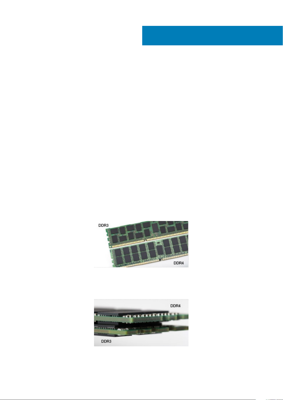
Key notch difference
The key notch on a DDR4 module is in a different location from the key notch on a DDR3 module. Both notches are on the insertion edge
but the notch location on the DDR4 is slightly different, to prevent the module from being installed into an incompatible board or platform.
Figure 1. Notch difference
Increased thickness
DDR4 modules are slightly thicker than DDR3, to accommodate more signal layers.
Figure 2. Thickness difference
Technology and components 7
Page 8
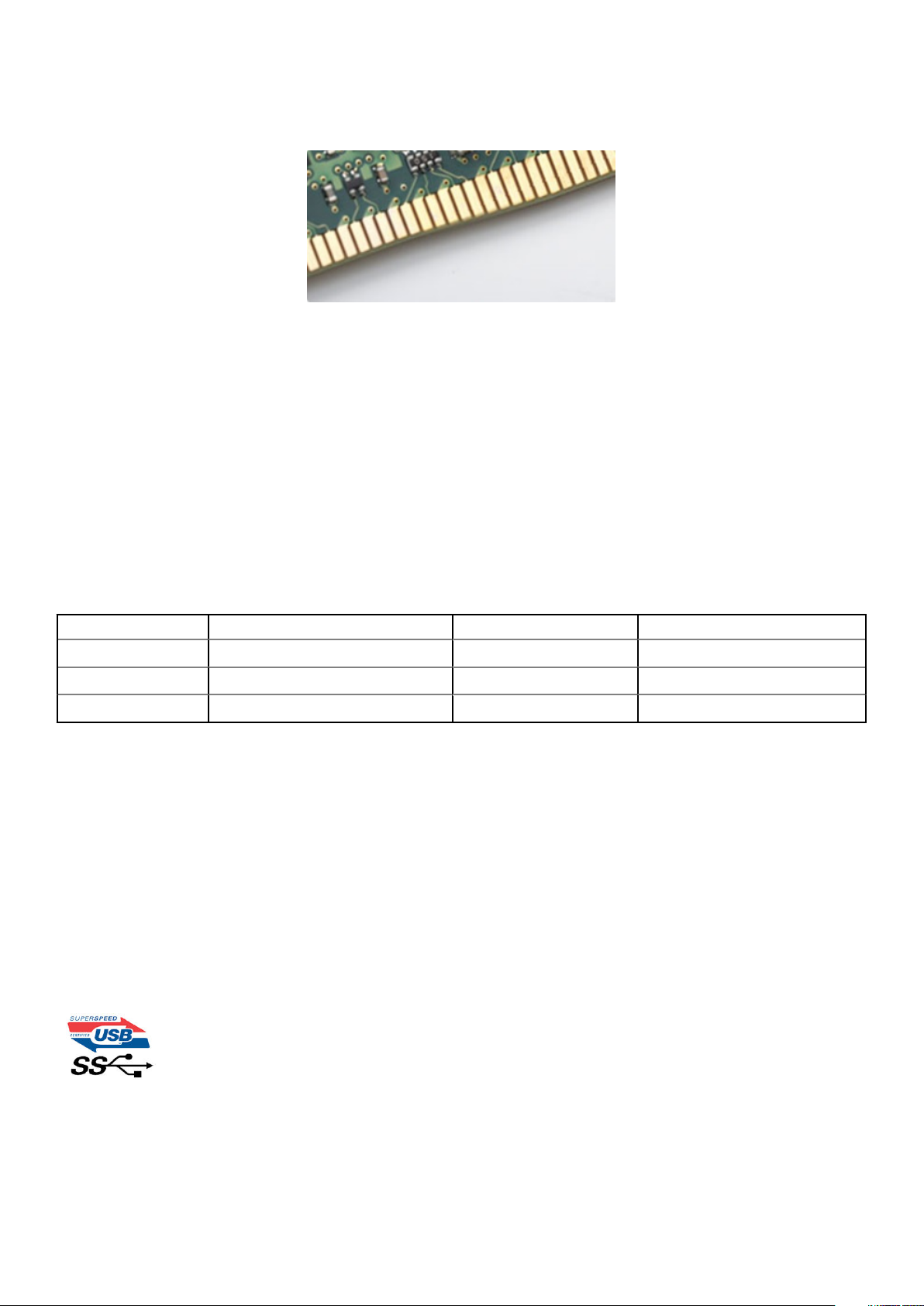
Curved edge
DDR4 modules feature a curved edge to help with insertion and alleviate stress on the PCB during memory installation.
Figure 3. Curved edge
Memory Errors
Memory errors on the system display the new ON-FLASH-FLASH or ON-FLASH-ON failure code. If all memory fails, the LCD does not
turn on. Troubleshoot for possible memory failure by trying known good memory modules in the memory connectors on the bottom of the
system or under the keyboard, as in some portable systems.
USB features
Universal Serial Bus, or USB, was introduced in 1996. It dramatically simplified the connection between host computers and peripheral
devices like mice, keyboards, external drivers, and printers.
Let's take a quick look on the USB evolution referencing to the table below.
Table 1. USB evolution
Type Data Transfer Rate Category Introduction Year
USB 3.0/USB 3.1 Gen 1 5 Gbps Super Speed 2010
USB 2.0 480 Mbps High Speed 2000
USB 3.1 Gen 2 10 Gbps Super Speed 2013
USB 3.0/USB 3.1 Gen 1 (SuperSpeed USB)
For years, the USB 2.0 has been firmly entrenched as the de facto interface standard in the PC world with about 6 billion devices sold, and
yet the need for more speed grows by ever faster computing hardware and ever greater bandwidth demands. The USB 3.0/USB 3.1 Gen 1
finally has the answer to the consumers' demands with a theoretically 10 times faster than its predecessor. In a nutshell, USB 3.1 Gen 1
features are as follows:
• Higher transfer rates (up to 5 Gbps)
• Increased maximum bus power and increased device current draw to better accommodate power-hungry devices
• New power management features
• Full-duplex data transfers and support for new transfer types
• Backward USB 2.0 compatibility
• New connectors and cable
The topics below cover some of the most commonly asked questions regarding USB 3.0/USB 3.1 Gen 1.
Speed
Currently, there are 3 speed modes defined by the latest USB 3.0/USB 3.1 Gen 1 specification. They are Super-Speed, Hi-Speed and FullSpeed. The new SuperSpeed mode has a transfer rate of 4.8Gbps. While the specification retains Hi-Speed, and Full-Speed USB mode,
8
Technology and components
Page 9
commonly known as USB 2.0 and 1.1 respectively, the slower modes still operate at 480Mbps and 12Mbps respectively and are kept to
maintain backward compatibility.
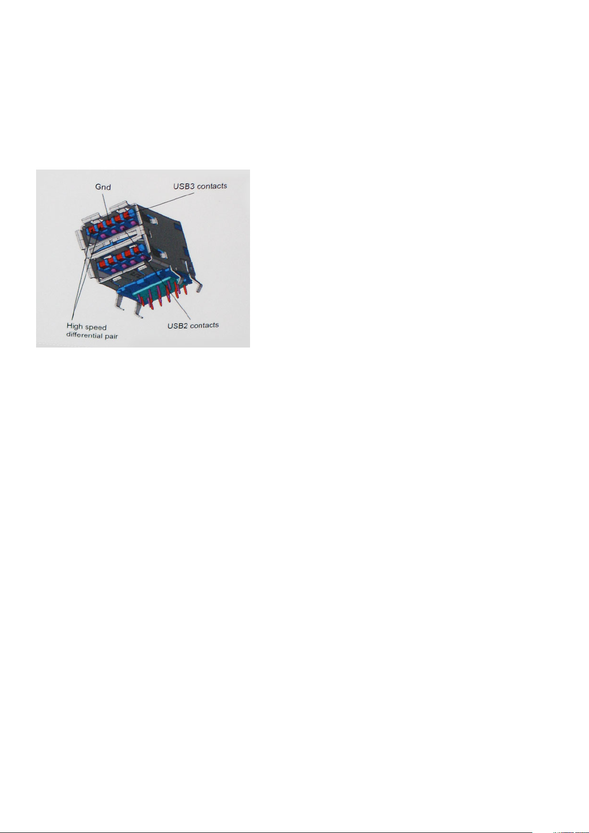
USB 3.0/USB 3.1 Gen 1 achieves the much higher performance by the technical changes below:
• An additional physical bus that is added in parallel with the existing USB 2.0 bus (refer to the picture below).
• USB 2.0 previously had four wires (power, ground, and a pair for differential data); USB 3.0/USB 3.1 Gen 1 adds four more for two
pairs of differential signals (receive and transmit) for a combined total of eight connections in the connectors and cabling.
• USB 3.0/USB 3.1 Gen 1 utilizes the bidirectional data interface, rather than USB 2.0's half-duplex arrangement. This gives a 10-fold
increase in theoretical bandwidth.
With today's ever increasing demands placed on data transfers with high-definition video content, terabyte storage devices, high
megapixel count digital cameras etc., USB 2.0 may not be fast enough. Furthermore, no USB 2.0 connection could ever come close to the
480Mbps theoretical maximum throughput, making data transfer at around 320Mbps (40MB/s) — the actual real-world maximum.
Similarly, USB 3.0/USB 3.1 Gen 1 connections will never achieve 4.8Gbps. We will likely see a real-world maximum rate of 400MB/s with
overheads. At this speed, USB 3.0/USB 3.1 Gen 1 is a 10x improvement over USB 2.0.
Applications
USB 3.0/USB 3.1 Gen 1 opens up the laneways and provides more headroom for devices to deliver a better overall experience. Where USB
video was barely tolerable previously (both from a maximum resolution, latency, and video compression perspective), it's easy to imagine
that with 5-10 times the bandwidth available, USB video solutions should work that much better. Single-link DVI requires almost 2Gbps
throughput. Where 480Mbps was limiting, 5Gbps is more than promising. With its promised 4.8Gbps speed, the standard will find its way
into some products that previously weren't USB territory, like external RAID storage systems.
Listed below are some of the available SuperSpeed USB 3.0/USB 3.1 Gen 1 products:
• External Desktop USB 3.0/USB 3.1 Gen 1 Hard Drives
• Portable USB 3.0/USB 3.1 Gen 1 Hard Drives
• USB 3.0/USB 3.1 Gen 1 Drive Docks & Adapters
• USB 3.0/USB 3.1 Gen 1 Flash Drives & Readers
• USB 3.0/USB 3.1 Gen 1 Solid-state Drives
• USB 3.0/USB 3.1 Gen 1 RAIDs
• Optical Media Drives
• Multimedia Devices
• Networking
• USB 3.0/USB 3.1 Gen 1 Adapter Cards & Hubs
Compatibility
The good news is that USB 3.0/USB 3.1 Gen 1 has been carefully planned from the start to peacefully co-exist with USB 2.0. First of all,
while USB 3.0/USB 3.1 Gen 1 specifies new physical connections and thus new cables to take advantage of the higher speed capability of
the new protocol, the connector itself remains the same rectangular shape with the four USB 2.0 contacts in the exact same location as
before. Five new connections to carry receive and transmitted data independently are present on USB 3.0/USB 3.1 Gen 1 cables and only
come into contact when connected to a proper SuperSpeed USB connection.
Technology and components
9
Page 10

Windows 8/10 will be bringing native support for USB 3.1 Gen 1 controllers. This is in contrast to previous versions of Windows, which
continue to require separate drivers for USB 3.0/USB 3.1 Gen 1 controllers.
Microsoft announced that Windows 7 would have USB 3.1 Gen 1 support, perhaps not on its immediate release, but in a subsequent
Service Pack or update. It is not out of the question to think that following a successful release of USB 3.0/USB 3.1 Gen 1 support in
Windows 7, SuperSpeed support would trickle down to Vista. Microsoft has confirmed this by stating that most of their partners share the
opinion that Vista should also support USB 3.0/USB 3.1 Gen 1.
USB Type-C
USB Type-C is a new, tiny physical connector. The connector itself can support various exciting new USB standards like USB 3.1 and USB
power delivery (USB PD).
Alternate Mode
USB Type-C is a new connector standard that is very small. It is about a third the size of an old USB Type-A plug. This is a single
connector standard that every device should be able to use. USB Type-C ports can support a variety of different protocols using
“alternate modes,” which allows you to have adapters that can output HDMI, VGA, DisplayPort, or other types of connections from that
single USB port
USB Power Delivery
The USB PD specification is also closely intertwined with USB Type-C. Currently, smartphones, tablets, and other mobile devices often
use a USB connection to charge. A USB 2.0 connection provides up to 2.5 watts of power — that'll charge your phone, but that's about
it. A laptop might require up to 60 watts, for example. The USB Power Delivery specification ups this power delivery to 100 watts. It's bidirectional, so a device can either send or receive power. And this power can be transferred at the same time the device is transmitting
data across the connection.
This could spell the end of all those proprietary laptop charging cables, with everything charging via a standard USB connection. You could
charge your laptop from one of those portable battery packs you charge your smartphones and other portable devices from today. You
could plug your laptop into an external display connected to a power cable, and that external display would charge your laptop as you used
it as an external display — all via the one little USB Type-C connection. To use this, the device and the cable have to support USB Power
Delivery. Just having a USB Type-C connection doesn't necessarily mean they do.
USB Type-C and USB 3.1
USB 3.1 is a new USB standard. USB 3's theoretical bandwidth is 5 Gbps same as of USB 3.1 Gen 1, while USB 3.1 Gen 2's bandwidth is 10
Gbps. That's double the bandwidth, as fast as a first-generation Thunderbolt connector. USB Type-C isn't the same thing as USB 3.1. USB
Type-C is just a connector shape, and the underlying technology could just be USB 2 or USB 3.0. In fact, Nokia's N1 Android tablet uses a
USB Type-C connector, but underneath it's all USB 2.0 — not even USB 3.0. However, these technologies are closely related.
Advantages of Displayport over USB Type-C
• Full DisplayPort audio/video (A/V) performance (up to 4K at 60Hz)
• Reversible plug orientation and cable direction
• Backwards compatibility to VGA, DVI with adaptors
• SuperSpeed USB (USB 3.1) data
• Supports HDMI 2.0a and is backwards compatible with previous versions
HDMI 2.0
This topic explains the HDMI 2.0 and its features along with the advantages.
HDMI (High-Definition Multimedia Interface) is an industry-supported, uncompressed, all-digital audio/video interface. HDMI provides an
interface between any compatible digital audio/video source, such as a DVD player, or A/V receiver and a compatible digital audio and/or
video monitor, such as a digital TV (DTV). The intended applications for HDMI TVs, and DVD players. The primary advantage is cable
reduction and content protection provisions. HDMI supports standard, enhanced, or high-definition video, plus multichannel digital audio
on a single cable.
10
Technology and components
Page 11

HDMI 2.0 Features
• HDMI Ethernet Channel - Adds high-speed networking to an HDMI link, allowing users to take full advantage of their IP-enabled
devices without a separate Ethernet cable
• Audio Return Channel - Allows an HDMI-connected TV with a built-in tuner to send audio data "upstream" to a surround audio
system, eliminating the need for a separate audio cable
• 3D - Defines input/output protocols for major 3D video formats, paving the way for true 3D gaming and 3D home theater applications
• Content Type - Real-time signaling of content types between display and source devices, enabling a TV to optimize picture settings
based on content type
• Additional Color Spaces - Adds support for additional color models used in digital photography and computer graphics
• 4K Support - Enables video resolutions far beyond 1080p, supporting next-generation displays that will rival the Digital Cinema
systems used in many commercial movie theaters
• HDMI Micro Connector - A new, smaller connector for phones and other portable devices, supporting video resolutions up to 1080p
• Automotive Connection System - New cables and connectors for automotive video systems, designed to meet the unique
demands of the motoring environment while delivering true HD quality
Advantages of HDMI
• Quality HDMI transfers uncompressed digital audio and video for the highest, crispest image quality.
• Low -cost HDMI provides the quality and functionality of a digital interface while also supporting uncompressed video formats in a
simple, cost-effective manner
• Audio HDMI supports multiple audio formats from standard stereo to multichannel surround sound
• HDMI combines video and multichannel audio into a single cable, eliminating the cost, complexity, and confusion of multiple cables
currently used in A/V systems
• HDMI supports communication between the video source (such as a DVD player) and the DTV, enabling new functionality
Technology and components
11
Page 12
Disassembly and reassembly
Side cover
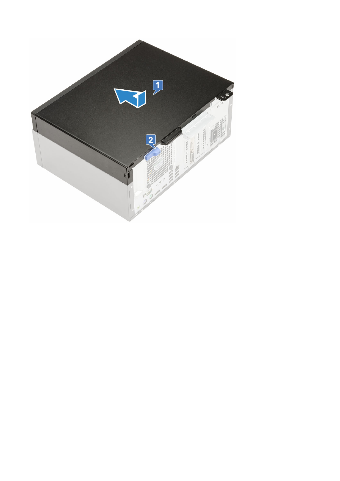
Removing side cover
1. Follow the procedure in Before working inside your computer.
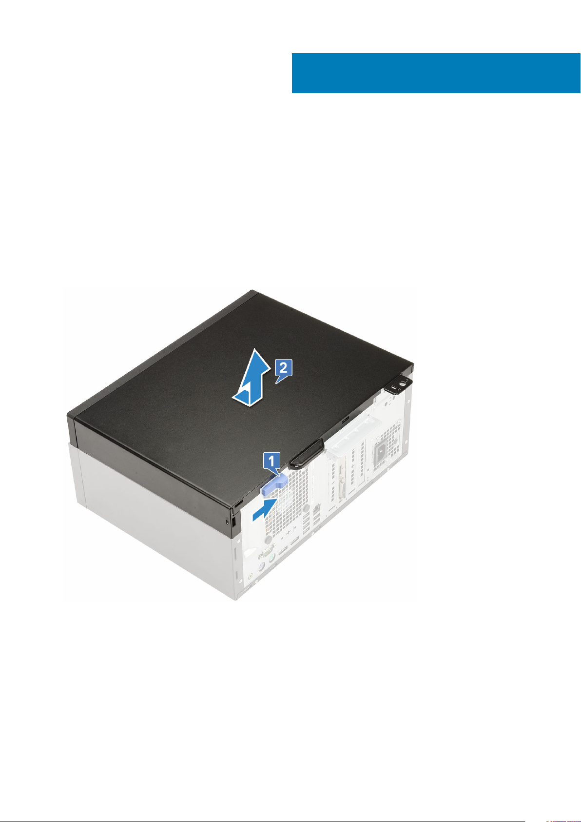
2. To release the side cover:
a) Slide the blue tab to release the side cover from the computer [1].
b) Slide the side cover toward the back of the computer [2].
c) Lift the side cover to remove it from the computer.
3
Installing side cover
1. Place the side cover on the computer and slide the side cover forward [1].
2. Slide the side cover until the click sound and the blue tab secures the side cover to the computer [2].
12 Disassembly and reassembly
Page 13
3. Follow the procedure in After working inside your computer.
Front Bezel
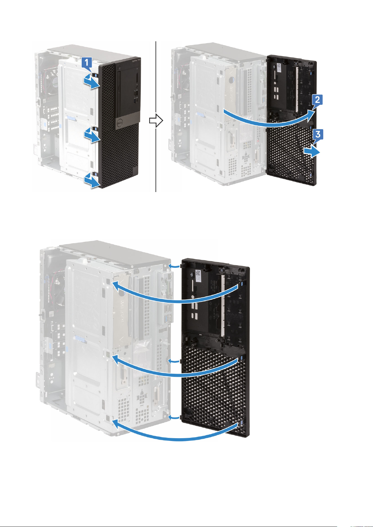
Removing front bezel
1. Follow the procedure in Before working inside your computer.
2. Remove the side cover.
3. To remove the front bezel:
a) Lift the tabs to release the front bezel from the chassis [1].
b) Push the front bezel away from the chassis [2] .
c) Pull the front bezel to release it from the chassis [3].
Disassembly and reassembly
13
Page 14
Installing front bezel
1. Position the front bezel to align the tab holders on the chassis.
2. Slide and press the front bezel until the tabs click in place.
3. Install the side cover.
4. Follow the procedure in After working inside your computer.
14
Disassembly and reassembly
Page 15
Front panel door
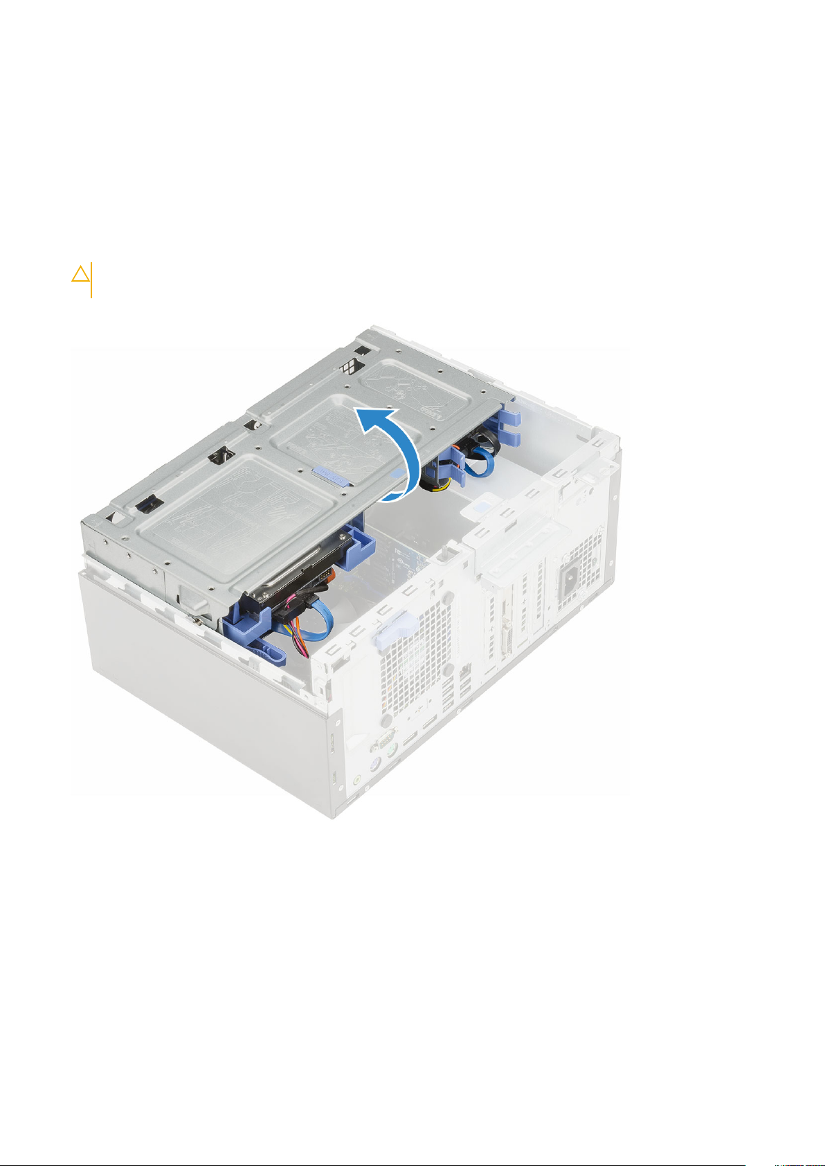
Opening the front panel door
1. Follow the procedure in Before working inside your computer.
2. Remove the:
a) side cover
b) front bezel
CAUTION: The front panel door opens only to a limited extent. See the printed image on the front panel door for the
maximum permissible level.
3. Pull the front panel door to open it.
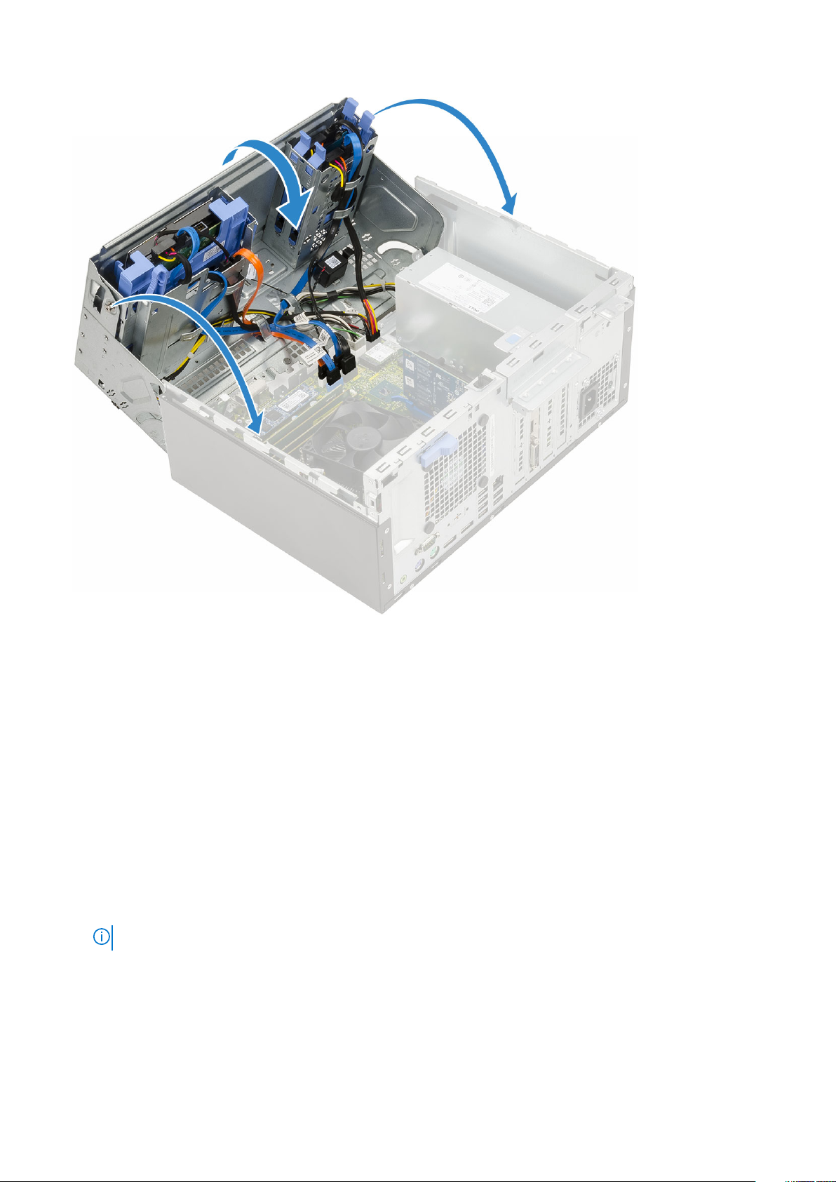
Closing front panel door
1. Push the front panel door on the computer and press the side cover forward until the panel door clicks into place.
Disassembly and reassembly
15
Page 16
2. Install the
a) front bezel
b) side cover
3. Follow the procedure in After working inside your computer.
3.5-inch hard drive
Removing 3.5–inch hard drive assembly
1. Follow the procedure in Before working inside your computer.
2. Remove the:
a) side cover
b) front bezel
3. To remove the hard drive assembly:
a) Disconnect the hard drive assembly cables from the connectors on the hard drive.
NOTE: Ensure to remove the SATA blue cable first, to ease in removing the hard drive data cable.
16 Disassembly and reassembly
Page 17
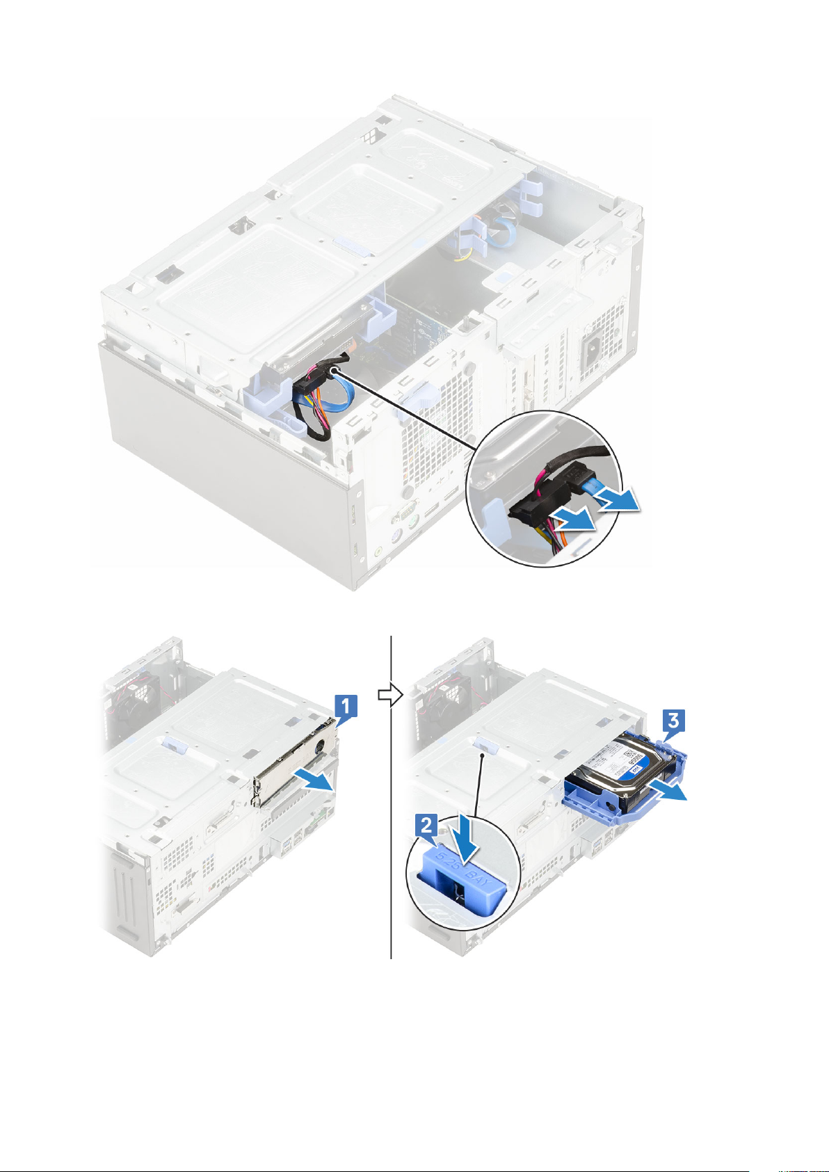
b) Pull the metal bracket that shields the hard drive assembly [1].
c) Press the blue tab [2] and pull the hard drive assembly out of the computer [ 3].
Installing 3.5–inch hard drive assembly
1. Insert the hard drive assembly into the slot on the computer until it clicks into place [1].
Disassembly and reassembly
17
Page 18
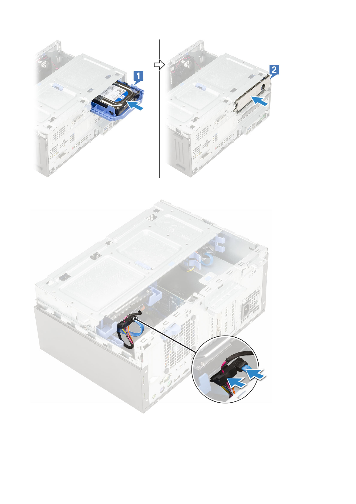
2. Close the metal bracket that shields the hard drive assembly [2].
3. Connect the SATA cable and the power cable to the connectors on the hard drive .
4. Install the:
a) front bezel
b) side cover
5. Follow the procedure in After working inside your computer.
18
Disassembly and reassembly
Page 19
3.5-inch hard drive
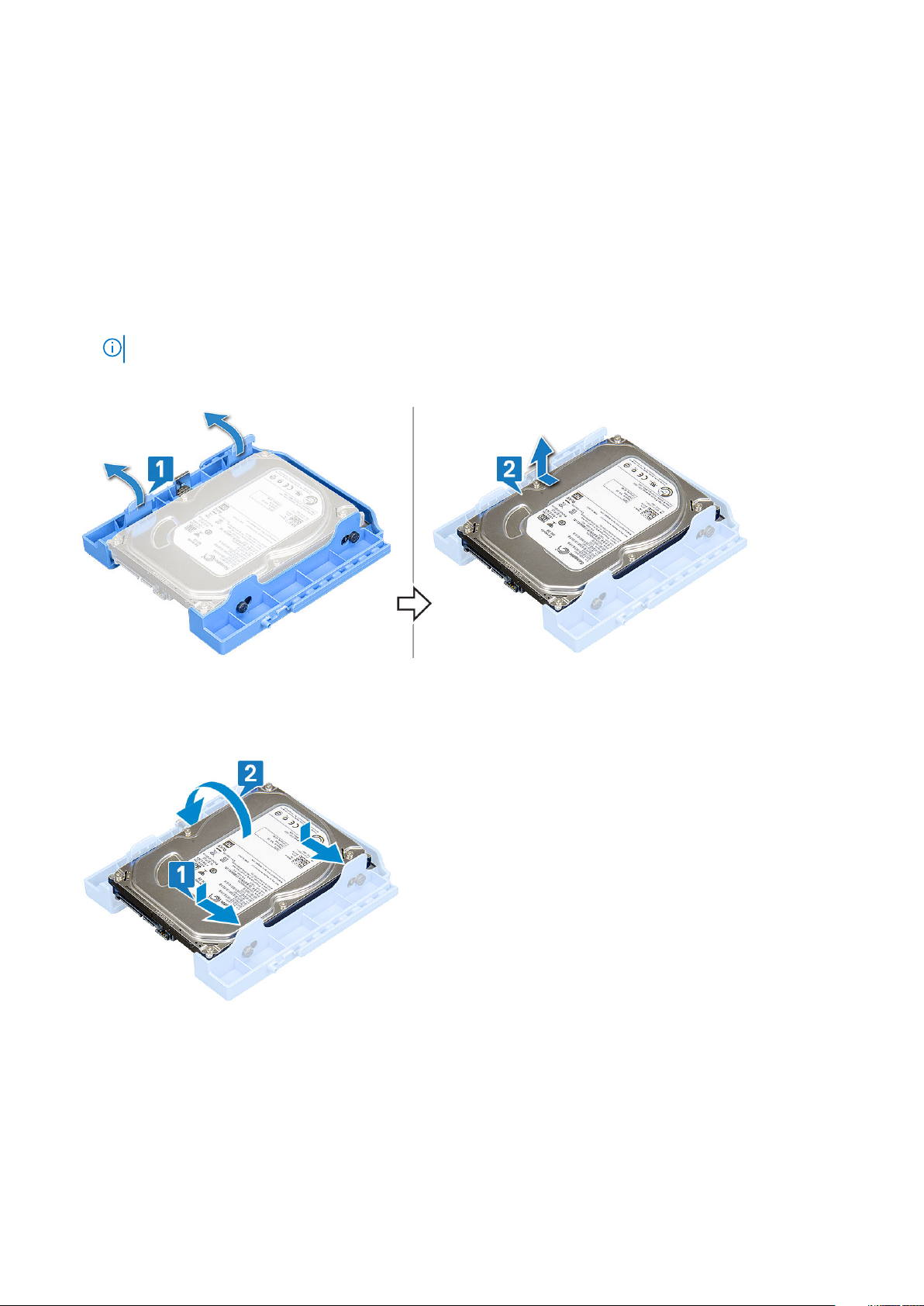
Removing 3.5–inch hard drive from the hard drive bracket
1. Follow the procedure in Before working inside your computer.
2. Remove the:
a) side cover
b) front bezel
c) 3.5-inch hard drive assembly
3. To remove the hard drive bracket:
a) Pull one side of the hard drive bracket to disengage the pins on the bracket from the slots on the hard drive [1].
NOTE: Do not pull plastic tab by more than 25° to avoid damage to the tabs.
b) Pull the hard drive out of the hard drive bracket.
c) Lift the hard drive out of the hard drive bracket [2].
Installing the 3.5–inch hard drive into the hard drive bracket
1. Align the hard drive to the side of the hard drive bracket, and pull the other end tabs to insert the pins on the bracket into the hard
drive [1].
2. Insert the hard drive into the hard drive bracket and press until it clicks into place [2].
3. Install the:
a) 3.5-inch hard drive assembly
b) front bezel
c) side cover
4. Follow the procedure in After working inside your computer.
Disassembly and reassembly
19
Page 20
2.5-inch hard drive assembly
Removing the 2.5–inch drive assembly
1. Follow the procedure in Before working inside your computer.
2. Remove the:
a) side cover
b) front bezel
3. Open the front panel door.
4. To remove the drive assembly:
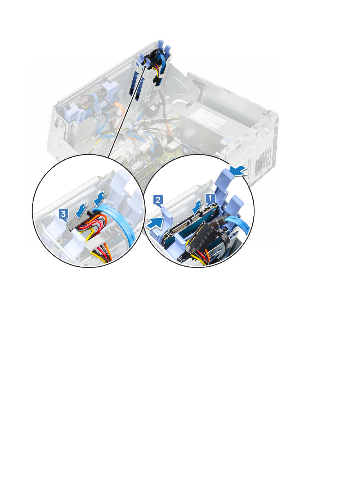
a) Disconnect the drive assembly cables from the connectors on the drive [1] .
b) Press the blue tabs on both sides [2] and pull the drive assembly out of the computer [3].
NOTE: Gently press the blue tabs to avoid damage to the plastic tabs.
Installing the 2.5-inch drive assembly
1. Insert the drive assembly into the slot on the computer and press until it clicks into place [1,2].
2. Connect the SATA cable and the power cable to the connectors on the drive [3].
20
Disassembly and reassembly
Page 21
3. Close the front panel door.
4. Install the:
a) front bezel
b) side cover
5. Follow the procedure in After Working Inside Your Computer.
2.5-inch hard drive
Removing the 2.5–inch drive from the drive bracket
1. Follow the procedure in Before Working Inside Your Computer.
2. Remove the:
a) side cover
b) front bezel
c) 2.5–inch drive assembly
3. To remove the drive:
a) Pull one side of the drive bracket to disengage the pins on the bracket from the slots on the drive [1].
b) Lift the drive out of the drive bracket [2].
Disassembly and reassembly
21
Page 22

Installing the 2.5–inch hard drive into the drive bracket
1. Align the hard drive to the side of the hard drive bracket, and pull the other end tabs to insert the pins on the bracket into the hard
drive.
2. Insert the hard drive into the hard drive bracket and press the hard drive until it clicks into place.
3. Install the:
a) 2.5–inch drive assembly
b) front bezel
c) cover
4. Follow the procedure in After working inside your computer.
Optical drive
Removing optical drive
1. Follow the procedure in Before working inside your computer.
2. Remove the:
a) side cover
b) front bezel
3. Open the front panel door.
4. To remove the optical drive assembly:
a) Disconnect the data cable and power cable from the connectors on the optical drive [1].
Ensure to unroute the cables from the tabs under the drive cage to allow you to disconnect the cables
NOTE:
from the connectors.
b) Close the front panel door [2].
22
Disassembly and reassembly
Page 23

c) Press the blue release tab [1] and slide the optical drive out of the computer [2].
Disassembly and reassembly
23
Page 24

Installing optical drive
1. Insert the optical drive into the optical drive bay until the blue release tab clicks into place.
24
Disassembly and reassembly
Page 25

2. Open the front panel door [2].
3. Route the data cable and power cable under the drive cage.
4. Connect the data cable and power cable to the connectors on the optical drive [3].
Disassembly and reassembly
25
Page 26

5. Close the front panel door.
6. Install the:
a) front bezel
b) side cover
7. Follow the procedure in After working inside your computer.
M.2 PCIe SSD
Removing M.2 PCle SSD - optional
1. Follow the procedure in Before working inside your computer.
2. Remove the:
a) side cover
b) front bezel
3. Open the front panel door.
4. To remove the M.2 PCIe SSD:
a) Remove the screw that secures the M.2 PCIe SSD to the system board [1].
b) Slide out the M.2 PCIe SSD from the connector on the system board [2].
26
Disassembly and reassembly
Page 27

Installing M.2 PCle SSD
1. Slide out the M.2 PCIe SSD from the connector on the system board [1].
2. Replace the screw that secures the M.2 PCIe SSD to the system board [2].
Disassembly and reassembly
27
Page 28

3. Close the front panel door.
4. Install the:
a) front bezel
b) side cover
5. Follow the procedure in After working inside your computer.
SD card reader
Removing SD card reader
1. Follow the procedure in Before working inside your computer.
2. Remove the:
a) side cover
b) front bezel
3. Open the front panel door.
4. To remove the SD card reader:
a) Disconnect the SD card reader cable from the connector on the system board [1].
b) Remove the screw that secures the SD card reader to the front panel door [2].
c) Lift the SD card reader out of the computer chassis [3].
28
Disassembly and reassembly
Page 29

Installing SD card reader
1. Insert the SD card reader into the slot on the front panel door [1].
2. Tighten the screw to secure the SD card reader to the front panel door [2].
3. Connect the SD card reader cable to the connector on the system board [3].
Disassembly and reassembly
29
Page 30

4. Close the front panel door.
5. Install the:
a) front bezel
b) side cover
6. Follow the procedure in After working inside your computer.
Memory module
Removing memory module
1. Follow the procedure in Before working inside your computer.
2. Remove the:
a) side cover
b) front bezel
3. Open the front panel door.
4. To remove the memory module:
a) Push the memory module retention tabs on both sides of the memory module [1].
b) Pull the memory module from the memory module connector on the system board [2].
NOTE: Follow the step 4a., 4b to remove the other memory modules.
30 Disassembly and reassembly
Page 31

Installing memory module
1. Align the notch on the memory module with the tab on the memory module connector.
2. Insert the memory module into the memory module socket [1].
3. Press the memory module until the memory module retention tabs click into place [2].
Disassembly and reassembly
31
Page 32

NOTE: Bison XE3 supports 4 memory module.
4. Close thefront panel door.
5. Install the:
a) front bezel
b) side cover
6. Follow the procedure in After working inside your computer.
Expansion card
Removing PCIe expansion card - optional
1. Follow the procedure in Before working inside your computer.
2. Remove the:
a) side cover
b) front bezel
3. Open the front panel door.
4. To remove the PCIe expansion card:
a) Pull the blue release tab that secures the PCIe expansion card to the system board [1].
b) Pull the card retention latch, and lift the PCIe expansion card from the connector on the system board [2,3].
The step is applicable only for the connector with card retention latch, otherwise, lift the PCIe expansion
NOTE:
card out of the computer.
32 Disassembly and reassembly
Page 33

5. Repeat the steps to remove any additional PCle expansion card
Installing PCIe expansion card
1. Insert the M.2 PCle Card to the connector and push the PCle Card to secure the card with the connector [1].
2. Release the card retention latch to secure the PCle expansion card [2].
Disassembly and reassembly
33
Page 34

3. Repeat the step 1 to install additional PCle expansion card.
4. Close the front panel door.
5. Install the:
a) front bezel
b) side cover
6. Follow the procedure in After working inside your computer.
Power supply unit
Removing power supply unit or PSU
1. Follow the procedure in Before working inside your computer.
2. Remove the:
a) side cover
b) front bezel
3. Open the front panel door.
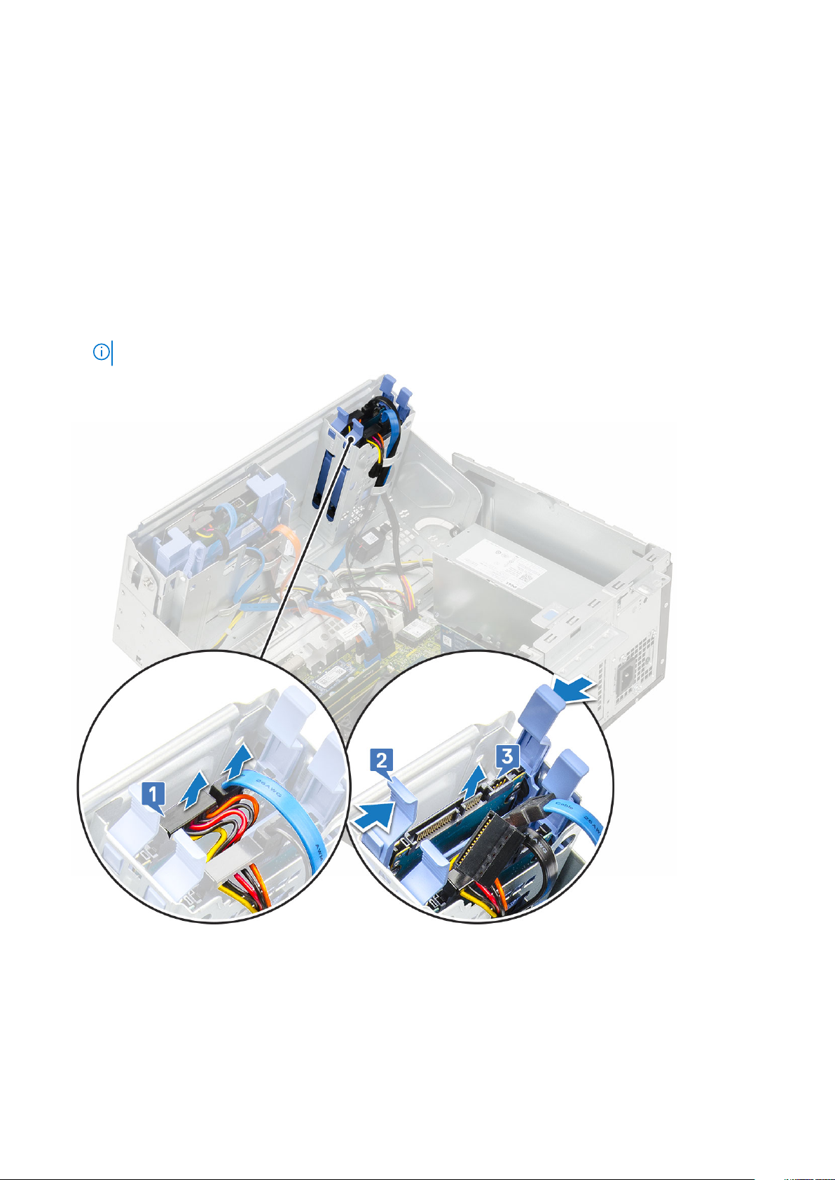
4. To release the PSU:
a) Press the latch and disconnect the PSU cables from the connectors on the system board [1].
b) Unroute the PSU cable from the retention clip to release the cable [2,3,4,5].
c) Press the latch and disconnect the cables from the connector on the system board [6].
34
Disassembly and reassembly
Page 35

5. To remove the PSU:
a) Remove the screw (3) to release the PSU from the computer chassis [1].
b) Press the release tab [2].
c) Slide and lift the PSU away from the computer [3].
Disassembly and reassembly
35
Page 36

Installing power supply unit or PSU
1. Insert the PSU into the PSU slot and slide it toward the back of the computer until it clicks into place{1,2]
36
Disassembly and reassembly
Page 37

2. Tighten the screws (3) to secure the PSU to the computer chassis [3].
3. Route the PSU cables through the retention clips [2,3,4,5].
4. Connect the PSU cables to the connectors on the system board [1,6].
Disassembly and reassembly
37
Page 38

5. Close the front panel door.
6. Install the:
a) front bezel
b) side cover
7. Follow the procedure in After working inside your computer.
Intrusion switch
Removing intrusion switch
1. Follow the procedure in Before working inside your computer.
2. Remove the:
a) side cover
b) front bezel
3. Open the front panel door.
4. To remove the intrusion switch:
a) Press the latch and disconnect the intrusion switch cable from the connector on the system board and pull the cable [1].
b) Unroute the intrusion switch cable from the fan grommet [2].
c) Slide the intrusion switch and push it to remove from the computer [3].
38
Disassembly and reassembly
Page 39

Installing intrusion switch
1. Insert the intrusion switch and slide the switch into the slot on the computer chassis [1].
2. Route the intrusion switch cable through the fan grommet [2].
3. Connect the intrusion switch cable to the connector on the system board [3].
Disassembly and reassembly
39
Page 40

4. Close the front panel door.
5. Install the:
a) front bezel
b) side cover
6. Follow the procedure in After working inside your computer.
Speaker
Removing speaker
1. Follow the procedure in Before working inside your computer.
2. Remove the:
a) side cover
b) front bezel
3. Open the front panel door.
4. To remove the speaker:
a) Disconnect the speaker cable from the connector on the system board [1].
b) Press the release tabs [2], and slide the speaker out of the slot [3].
40
Disassembly and reassembly
Page 41

Installing speaker
1. Insert the speaker into the slot [1] and slide it until it clicks into place [2].
2. Connect the speaker cable to the connector on the system board [3].
Disassembly and reassembly
41
Page 42

3. Close the front panel door.
4. Install the:
a) front bezel
b) side cover
5. Follow the procedure in After working inside your computer.
Power button
Removing power button
1. Follow the procedure in Before working inside your computer.
2. Remove the:
a) side cover
b) front bezel
3. Open the front panel door.
4. To release the power switch:
a) Pull the socket to disconnect the power switch cable from the system board [1].
b) Unroute the power switch cable through the retention clip [2].
c) Press the release tabs using a plastic scribe and slide the power switch out from the front of the computer [3].
d) Close the front panel door [4].
42
Disassembly and reassembly
Page 43

5. Pull the power switch out from the computer.
Disassembly and reassembly
43
Page 44

Installing power button
1. Insert the power switch into the slot from the front of the computer.
44
Disassembly and reassembly
Page 45

2. Open the front panel [1].
3. Press the power switch to the slot on the computer chassis [2].
4. Route the power switch cable through the retention clip [3].
5. Align the cable with the pins on the connector and push to connect the cable.
Disassembly and reassembly
45
Page 46

6. Close the front panel door.
7. Install the:
a) front bezel
b) side cover
8. Follow the procedure in After working inside your computer.
Heat sink fan
Removing heat sink fan
1. Follow the procedure in Before working inside your computer.
2. Remove the:
a) side cover
b) front bezel
3. Open the front panel door.
4. To remove the heat sink fan:
a) Disconnect the heat sink assembly cable from the connector on the system board [1].
b) Remove the screws that secure the fan to the heat sink [2].
NOTE: Ensure to insert the Torx screw driver from top screw hole to remove the screws.
c) Lift the heat sink fan away from the computer [3].
46
Disassembly and reassembly
Page 47

Installing heat sink fan
1. Place the fan on the heat sink [1].
2. Tighten the screws (4) to secure the fan to the heat sink [2].
3. Connect the heat sink assembly cable to the connector on the system board [3].
Disassembly and reassembly
47
Page 48

4. Close the front panel door.
5. Install the:
a) front bezel
b) side cover
6. Follow the procedure in After working inside your computer.
Coin cell battery
Removing coin cell battery
1. Follow the procedure in Before working inside your computer.
2. Remove the:
a) side cover
b) front bezel
3. Open the front panel door.
4. To remove the coin cell battery:
a) Press the release latch until the coin cell battery pops out [1].
b) Lift the coin cell battery from the connector on the system board [2].
48
Disassembly and reassembly
Page 49

Installing coin cell battery
1. Hold the coin cell battery with the "+" sign facing up and slide it under the securing tabs at the positive side of the connector [1].
2. Press the battery into the connector until it locks into place [2].
Disassembly and reassembly
49
Page 50

3. Close the front panel door.
4. Install the:
a) front bezel
b) side cover
5. Follow the procedure in After working inside your computer.
Heat sink
Removing heat sink
1. Follow the procedure in Before working inside your computer.
2. Remove the:
a) side cover
b) bezel
3. Open the front panel door.
4. Remove the heatsink fan.
5. To remove the heat sink:
a) Loosen the captive screws (4) that secure the heat sink to the system board [1].
NOTE: Remove the screw in the sequential order (1,2,3,4) as printed on the system board.
b) Lift the heat sink away from the computer [2].
50
Disassembly and reassembly
Page 51

Installing heat sink
1. Align the screws of the heat sink with the holders on the system board and place the heat sink on the processor [1].
2. Tighten the captive screws to secure the heat sink assembly to the system board [2].
NOTE:
Tighten the screws in a sequential order (1,2,3,4) as printed on the system board.
Disassembly and reassembly
51
Page 52

3. Replace the heat sink fan.
4. Close the front panel door.
5. Install the:
a) front bezel
b) side cover
6. Follow the procedure in After working inside your computer.
Processor
Removing processor
1. Follow the procedure in Before working inside your computer.
2. Remove the:
a) side cover
b) front bezel
3. Open the front panel door.
4. Remove the heat sink fan
5. Remove the heat sink.
6. To remove the processor:
a) Release the socket lever by pushing the lever down and out from under the tab on the processor shield [1].
b) Lift the lever upward until the lever pops out of the processor shield [2].
c) Lift the processor out of the socket [3].
CAUTION:
not to bend the pins in the processor socket when removing the processor out of the socket.
Do not touch the processor socket pins, they are fragile and can be permanently damaged. Be careful
52 Disassembly and reassembly
Page 53

Installing processor
1. Place and align the processor on the socket such that the slots on the processor align with the socket keys [1].
CAUTION:
the socket.
2. Close the processor shield by sliding it under the retention screw [2].
3. Lower the socket lever and push it under the tab to lock and secure the processor [3].
Do not use force to seat the processor. When the processor is positioned correctly, it engages easily into
Disassembly and reassembly
53
Page 54

4. Install the heat sink.
5. Install the heat sink fan
6. Close the front panel door
7. Install the:
a) front bezel
b) side cover
8. Follow the procedure in After working inside your computer.
System fan
Removing system fan
1. Follow the procedure in Before working inside your computer.
2. Remove the:
a) side cover
b) front bezel
c) intrusion switch
3. Open the front panel door.
4. To remove the system fan:
a)
NOTE: Ensure to remove the intrusion switch before uninstalling the system fan.
54 Disassembly and reassembly
Page 55

Disconnect the system fan cable from the connector on the system board [1].
b) Stretch the grommets (4) securing the fan to the computer to ease the removal of the system fan [2].
c) Lift the system fan out of the computer [3].
Installing system fan
1. Align the grooves of the system fan with the grommets on the chassis wall [1].
2. Pass the grommets through the corresponding grooves on the system fan.
3. Stretch the grommets and slide the system fan toward the computer until it locks into place [2].
NOTE: Install the lower two grommets first.
4. Connect the system fan cable to the connector on the system board [3].
Disassembly and reassembly
55
Page 56

5. Close the front panel door.
6. Install the:
a) intrusion switch
b) front bezel
c) side cover
7. Follow the procedure in After working inside your computer.
Optional VGA module
Removing optional VGA module
1. Follow the procedure in Before working inside your computer.
2. Remove the:
a) Side cover
b) Front bezel
3. Open the front panel door
4. Remove the system fan.
5. To remove the optional VGA module:
a) Remove the two (M3X3) screws that secure the optional VGA module to the system.
56
Disassembly and reassembly
Page 57

b) Disconnect the VGA cable from the connector on the system board [1].
c) Remove the VGA module from the system [2].
Installing optional VGA module
1. Insert the VGA module into its slot from the inside of your computer [1] and connect the VGA cable to the connector on the system
board [2].
2. Replace the two (M3X3) screws to secure the optional VGA module to the system.
Disassembly and reassembly
57
Page 58

3. Install the system fan.
4. Close the front panel door.
5. Install the:
a) Front bezel
b) Side cover
6. Follow the procedure in After working inside your computer.
System board
Removing system board
1. Follow the procedure in Before working inside your computer.
2. Remove the:
a) side cover
b) front bezel
3. Open the front panel door.
4. Remove the:
a) heat sink fan
b) heat sink
c) processor
d) expansion card
e) M.2 PCle SSD
f) SD card reader
g) memory module
5. Disconnect the following cables from the system board:
a) PSU [1]
b) power cable and SATA cable [2]
c) speaker [3]
d) PSU [4]
e) power distribution for optical drive and hard drive [5]
58
Disassembly and reassembly
Page 59

6. To remove the system board:
a) Remove the screws (8) that secure the system board to the computer chassis.
Disassembly and reassembly
59
Page 60

b) Slide and lift the system board away from the computer [1, 2].
60
Disassembly and reassembly
Page 61

Installing the system board
1. Hold the system board by its edges and align it toward the back of the computer [1,2].
2. Lower the system board into the computer until the connectors at the back of the system board align with the slots on the chassis,
and the screw holes on the system board align with the standoffs on the computer.
3. Tighten the screws (8) to secure the system board to the computer [1].
Disassembly and reassembly
61
Page 62

4. Align the cables with the pins on connectors on the system board and connect the following cables to the system board:
5. Route all the cables through the routing clips.
a) power distribution for optical drive and hard drives [1]
b) PSU [2]
c) speaker cable [3]
d) SATA data cable for optical dive and hard drive cables (4 cables) [4]
e) PSU cable [5]
62
Disassembly and reassembly
Page 63

6. Install the:
a) memory module
b) M.2 PCle SSD
c) expansion card
d) SD card reader
e) processor
f) heat sink
g) heat sink fan
7. Close the front panel door.
8. Install the:
a) front bezel
b) side cover
9. Follow the procedure in After working inside your computer.
Disassembly and reassembly
63
Page 64

4
Troubleshooting
Enhanced Pre-Boot System Assessment — ePSA diagnostics
The ePSA diagnostics (also known as system diagnostics) performs a complete check of your hardware. The ePSA is embedded with the
BIOS and is launched by the BIOS internally. The embedded system diagnostics provides a set of options for particular devices or device
groups allowing you to:
• Run tests automatically or in an interactive mode
• Repeat tests
• Display or save test results
• Run thorough tests to introduce additional test options to provide extra information about the failed device(s)
• View status messages that inform you if tests are completed successfully
• View error messages that inform you of problems encountered during testing
CAUTION: Use the system diagnostics to test only your computer. Using this program with other computers may cause
invalid results or error messages.
NOTE: Some tests for specific devices require user interaction. Always ensure that you are present at the computer
terminal when the diagnostic tests are performed.
Running the ePSA Diagnostics
1. Invoke diagnostics boot by either of the methods suggested above
2. Once on one time boot menu use up/down arrow key to navigate to ePSA or diagnostics and press <return> key to launch
Fn+PWR will flash diagnostics boot selected on screen and launch ePSA/diagnostics directly.
3. On the boot menu screen, select the Diagnostics option.
4. Press the arrow in the lower-right corner to go to the page listing.
The items detected are listed and will be tested
5. If there are any issues, error codes are displayed.
Note the error code and validation number and contact Dell.
To run a diagnostic test on a specific device
1. Press Esc and click Yes to stop the diagnostic test.
2. Select the device from the left pane and click Run Tests.
3. If there are any issues, error codes are displayed.
Note the error code and validation number and contact Dell.
Diagnostics
The computer POST (Power On Self Test) ensures that it meets the basic computer requirements and the hardware is working
appropriately before the boot process begins. If the computer passes the POST, the computer continues to start in a normal mode.
However, if the computer fails the POST, the computer emits a series of LED codes during the start-up. The system LED is integrated on
the Power button.
The following table shows different light patterns and what they indicate.
64 Troubleshooting
Page 65

Table 2. Power LED summary
Amber LED state White LED state System state Notes
Off Off S5
Off Blinking S3, no PWRGD_PS
Previous State Previous State S3, no PWRGD_PS This entry provides for the
possibility of a delay from
SLP_S3# active to PWRGD_PS
inactive.
Blinking Off S0, no PWRGD_PS
Steady Off S0, no PWRGD_PS, Code fetch
= 0
Off Steady S0, no PWRGD_PS, Code fetch
= 1
Table 3. Amber LED blinking failures
Amber LED state White LED state System state Notes
2,1 Bad MBD Bad MBD - Rows A, G, H, and J
2,2 Bad MB, PSU or cabling Bad MBD, PSU or PSU cabling -
2,3 Bad MBD, DIMMS, or CPU Bad MBD, DIMMS or CPU -
2,4 Bad coin cell Bad coin cell - Row M of table
This indicates that the host
BIOS has started to execute and
the LED register is now writable.
from table 12.4 of SIO Spec Pre-Post indicators [40]
Rows B, C and D of table 12.4
SIO spec [40]
Rows F and K from table 12.4 of
SIO spec [40]
12.4 in SIO spec [40]
Table 4. States Under Host BIOS Control
Amber LED state White LED state System state Notes
2,5 BIOS state 1 BIOS Post code (Old LED
pattern 0001) Corrupt BIOS.
2,6 BIOS state 2 BIOS Post code (Old LED
pattern 0010) CPU config or
CPU failure.
2,7 BIOS state 3 BIOS Post code (Old LED
pattern 0011) MEM config in
process. Appropriate mem
modules detected but failure has
occurred.
3,1 BIOS state 4 BIOS Post code (Old LED
pattern 0100) Combine PCI
device config or failure with
video sub sytem config or failure.
BIOS to eliminate 0101 video
code.
3,2 BIOS state 5 BIOS Post code (Old LED
pattern 0110) Combine storage
and USB config or failure. BIOS
to eliminate 0111 USB code.
Troubleshooting 65
Page 66

Amber LED state White LED state System state Notes
3,3 BIOS state 6 BIOS Post code (Old LED
pattern 1000) MEM config, no
memory detected.
3,4 BIOS state 7 BIOS Post code (Old LED
pattern 1001) Fatal Motherboard
error.
3,5 BIOS state 8 BIOS Post code (Old LED
pattern 1010) Mem config,
modules incompatible or invalid
config.
3,6 BIOS state 9 BIOS Post code (Old LED
pattern 1011) combine "Other
pre-video activity and resource
configuration codes. BIOS to
eliminate 1100 code.
3,7 BIOS state 10 BIOS Post code (Old LED
pattern 1110) Other pre-post
activity, routine subsequent to
video init.
Battery status lights
If the computer is connected to an electrical outlet, the battery light operates as follows:
Alternately
blinking amber
light and white
light
Alternately
blinking amber
light with steady
white light
Constantly
blinking amber
light
Light off Battery in full charge mode with AC adapter present.
White light on Battery in charge mode with AC adapter present.
An unauthenticated or unsupported non-Dell AC adapter is attached to your laptop. Re-plug battery connector,
replace battery if the issue reoccurs.
Temporary battery failure with AC adapter present. Re-plug battery connector, replace battery if the issue
reoccurs.
Fatal battery failure with AC adapter present. Fetal battery, replace the battery.
66 Troubleshooting
Page 67

5
Getting help
Topics:
• Contacting Dell
Contacting Dell
NOTE: If you do not have an active Internet connection, you can find contact information on your purchase invoice,
packing slip, bill, or Dell product catalog.
Dell provides several online and telephone-based support and service options. Availability varies by country and product, and some services
may not be available in your area. To contact Dell for sales, technical support, or customer service issues:
1. Go to Dell.com/support.
2. Select your support category.
3. Verify your country or region in the Choose a Country/Region drop-down list at the bottom of the page.
4. Select the appropriate service or support link based on your need.
Getting help 67
 Loading...