

Page 1
Setup and Features Information
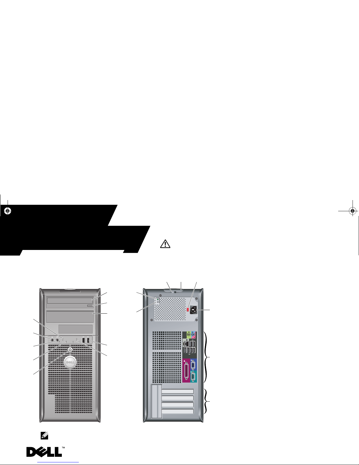
Mini Tower — Front and Back View
1 optical drive
2 optical drive eject button
3 optical drive panel
4 USB 2.0 connectors (2)
5 drive activity light
6 power button, power light
7 diagnostic lights (4)
8 headphone connector
9 microphone connector
10 link integrity light
11 padlock ring
12 cover-release latch, security cable slot
13 voltage selector switch
14 power cable connector
15 back panel connectors
16 expansion card slots (4)
17 power supply diagnostic button
18 power supply diagnostic light
2
9
8
6
4
5
3
10
7
17
12
13
14
15
16
11
18
1
NOTE: The voltage selector switch is available only on non-EPA power supplies.
Models: DCSM1F, DCNE1F, and DCCY1F series
Dell™ OptiPlex™ 380
About Warnings
WARNING: A WARNING indicates a potential
for property damage, personal injury, or death.
March 2010
Y705RA01MR.fm Page 1 Tuesday, March 30, 2010 9:06 AM
Page 2

Desktop — Front and Back View
1
3
4
6
98
7
2
5
1 optical drive
2 optical drive eject button
3 USB 2.0 connectors (2)
4 drive activity light
5 diagnostic lights (4)
6 power button, power light
7 link integrity light
8 microphone connector
9 headphone connector
10 power supply diagnostic button
11 power supply diagnostic light
12 voltage selector switch
13 cover-release latch, security cable slot
14 padlock ring
15 power cable connector
16 back panel connectors
17 expansion card slots (3)
10
12
16
14
13
17
11
15
NOTE: The voltage selector switch is available only on non-EPA power supplies.
Y705RA01MR.fm Page 2 Tuesday, March 30, 2010 9:06 AM
Page 3

Small Form Factor — Front and Back View
1 optical drive
2 optical drive eject button
3 USB 2.0 connectors (2)
4 power button, power light
5 link integrity light
6 diagnostic lights (4)
7 drive activity light
8 headphone connector
9 microphone connector
10 power supply diagnostic button
11 power supply diagnostic light
12 cover-release latch, security cable slot
13 padlock ring
14 voltage selector switch
15 power cable connector
16 back panel connectors
17 expansion card slots (2)
1
2
3
4
6
7
89
5
14
16
17
13
12
10
11
15
NOTE: The voltage selector switch is available only on non-EPA power supplies.
Y705RA01MR.fm Page 3 Tuesday, March 30, 2010 9:06 AM
Page 4
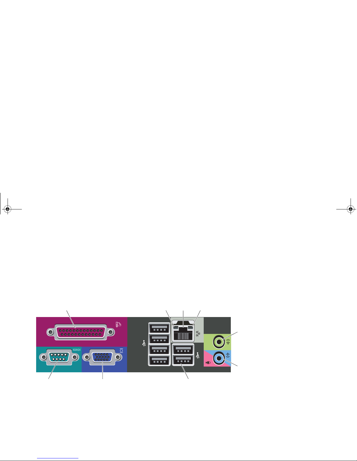
Mini Tower, Desktop, and Small Form Factor — Back Panel
1 parallel connector
2 link integrity light
3 network adapter connector
4 network activity light
5 line-out connector
6 line-in/microphone connector
7 USB 2.0 connectors (6)
8 VGA connector
9 serial connector
14
7
89
2
3
5
6
Y705RA01MR.fm Page 4 Tuesday, March 30, 2010 9:06 AM
Page 5
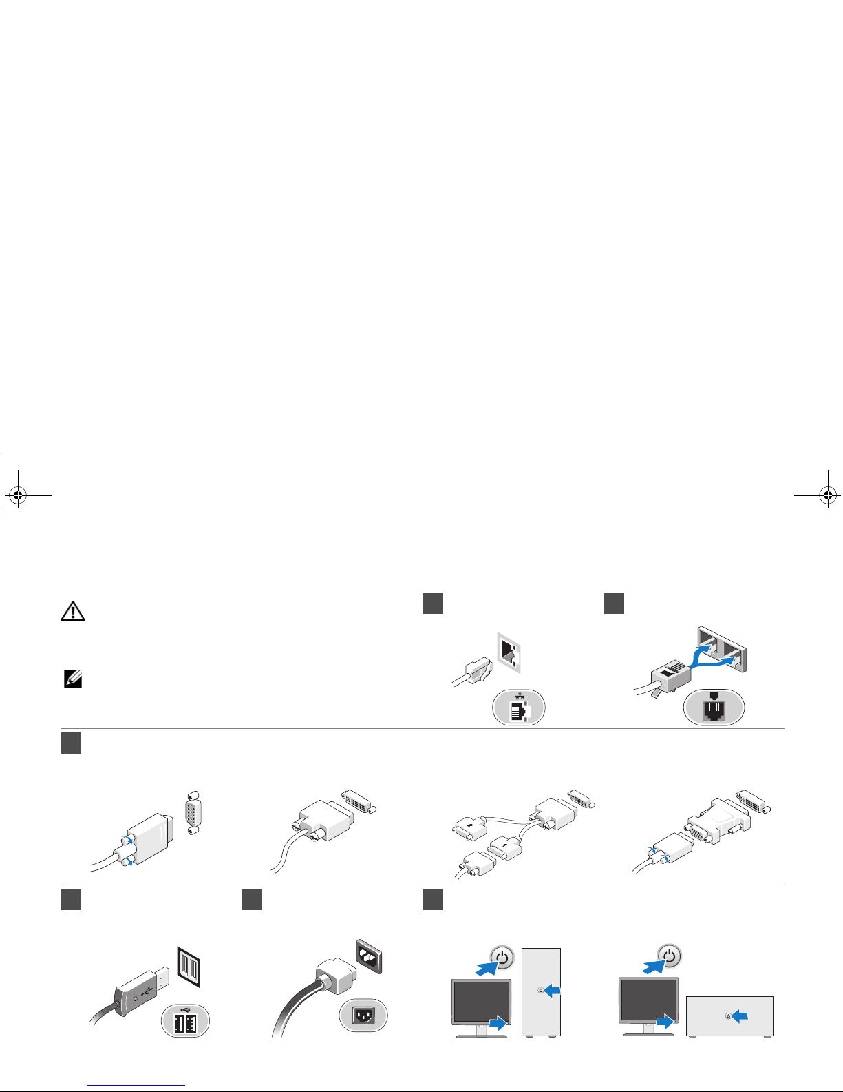
1
Connect the network cable
(optional).
2
Connect the modem
(optional).
3
Connect the monitor using only one of the following cables:
a The blue VGA cable. b The white DVI cable. c The dual monitor
Y-adapter cable.
d The VGA cable to
DVI adapter.
4 Connect the
USB keyboard or
mouse (optional).
5 Connect the
power cable(s).
6 Press the power buttons on the monitor and the computer.
Quick Setup
WARNING: Before you begin any of the procedures
in this section, read the safety information that shipped
with your computer. For additional best practices
information, see www.dell.com/regulatory_compliance.
NOTE: Some devices may not be included if you did
not order them.
Y705RA01MR.fm Page 5 Tuesday, March 30, 2010 9:06 AM
Page 6
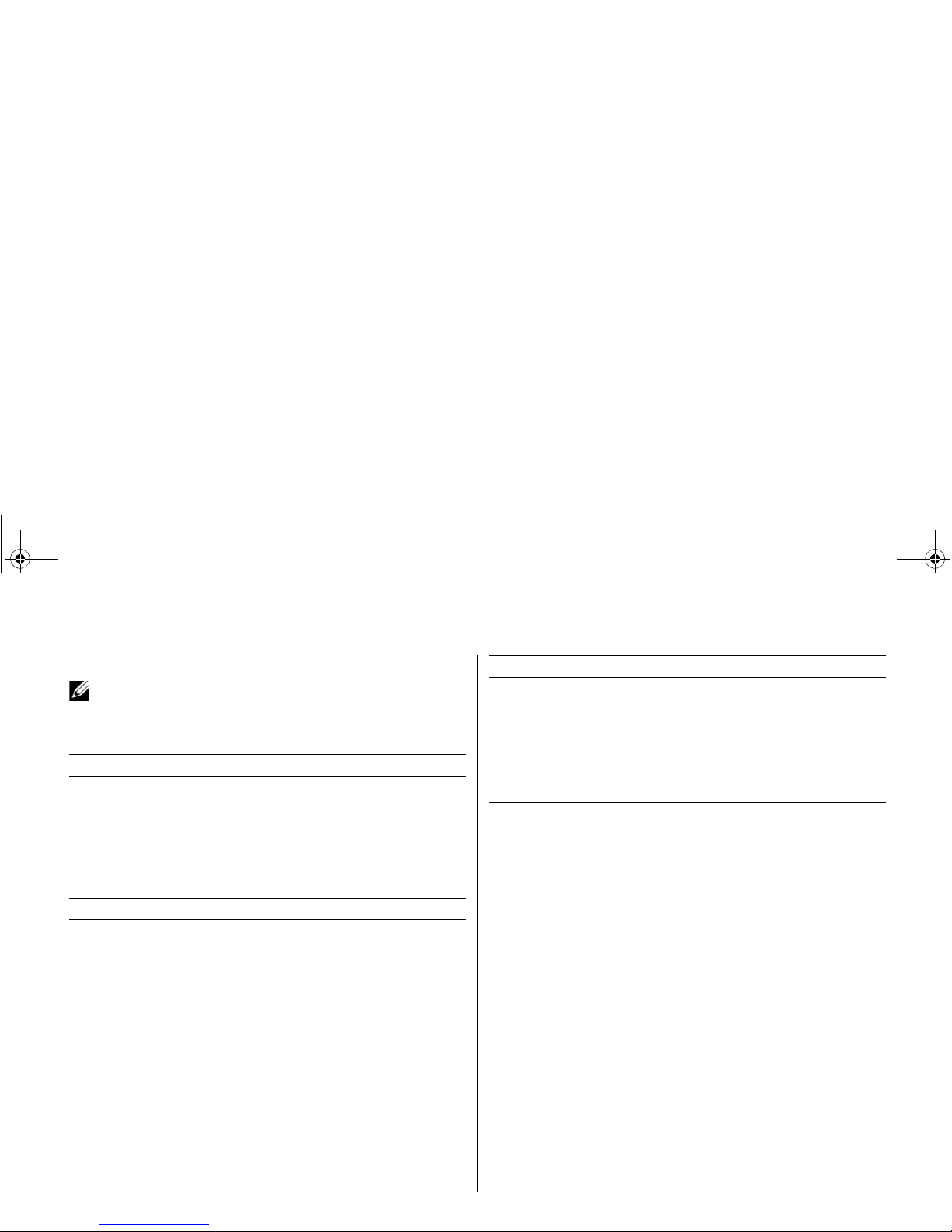
Specifications
NOTE: The following specifications are only those required by law
to ship with your computer. For a complete and current listing of the
specifications for your computer, go to support.dell.com.
System Information
Chipset Intel® G41 Express Chipset
Processor
• Intel Core™2 Quad
• Intel Core2 Duo
• Intel Pentium
®
Dual-Core
• Intel Celeron
®
Dual-Core
• Intel Celeron
Video
Video type:
Integrated
integrated on system board
Discrete
PCI-E x16 half-length graphics card
with 2 DVI and 1 S-Video out,
or 1 DVI, 1 VGA, and 1 S-Video out
• NVIDIA GeForce 9300 GE
• ATI Radeon HD 3450
Video memory:
Integrated
up to 256 MB shared video memory
(with 1 GB system memory)
up to 352 MB shared video memory
(with 2, 3, or 4 GB system memory)
Discrete
256 MB
Memory
Memory module connector 2 DIMM slots
Memory module capacity 1 GB, 2 GB, or 4 GB
Memory type 1067 MHz DDR3
Minimum memory 1 GB
Maximum memory 8 GB
Drives
Mini Tower Desktop Small Form
Factor
Externally accessible:
3.5 inch drive bays
one one one
5.25 inch drive bays
two one one (slimline)
Internally accessible:
3.5 inch SATA
drive bays
two one one
Available devices:
3.5 inch SATA
hard drives
two one one
5.25 inch SATA
DVD-ROM,
DVD/CD-RW Combo,
or DVD+/-RW drives
two one one (slimline)
Y705RA01MR.fm Page 6 Tuesday, March 30, 2010 9:06 AM
Page 7
Control Lights and Diagnostic Lights
Power button light Green light — Solid green light indicates
power-on state; blinking green light
indicates sleep state of the computer.
Amber light — Solid amber light when the
computer does not start indicates a problem
with the system board or power supply.
Blinking amber light indicates a problem
with the system board.
Drive activity light Displays the SATA hard drive or optical
drive activity.
Green light — Blinking green light
indicates that the computer is reading
data from or writing data to the drive.
Network connectivity light Green light — A good connection exists
between the network and the computer.
Off (no light) — The computer is not
detecting a physical connection to the network.
Diagnostic lights Four lights located on the front/back panel
of the computer. For information on the
diagnostic lights, see the Service Manual
available on the Dell Support website at
support.dell.com/manuals.
Power
Wa tt a g e
Maximum heat
dissipation
Vo lt ag e
Mini Tower:
Non-EPA
255 W 1338 (BTU/hr) 115/230 VAC,
50/60 Hz, 6.5/3.5 A
EPA
255 W 1023 (BTU/hr) 100-240 VAC,
50/60 Hz, 1.8/3.6 A
Desktop:
Non-EPA
235 W 1233 (BTU/hr) 115/230 VAC,
50/60 Hz, 6.5/3.5 A
EPA
255 W 1023 (BTU/hr) 100-240 VAC,
50/60 Hz, 2.0/4.0 A
Small Form Factor:
Non-EPA
235 W 1233 (BTU/hr) 115/230 VAC,
50/60 Hz, 6.5/3.5 A
EPA
235 W 943 (BTU/hr) 100-240 VAC,
50/60 Hz, 1.75/3.5 A
NOTE: Heat dissipation is calculated by using the power supply
wattage rating.
NOTE: See the safety information that shipped with your computer for
important voltage–setting information.
Coin-cell battery 3V CR2032 lithium coin cell
Y705RA01MR.fm Page 7 Tuesday, March 30, 2010 9:06 AM
Page 8
Finding More Information and Resources
________________
Information in this document is subject to change without notice.
© 2009–2010 Dell Inc. All rights reserved.
Reproduction of these materials in any manner whatsoever without the written
permission of Dell Inc. is strictly forbidden.
Trademarks used in this text: Dell, the DELL logo, and OptiPlex are trademarks
of Dell Inc.; Intel, Pentium, and Celeron are registered trademarks and Core is
a trademark of Intel Corporation in the U.S. and other countries.
Other trademarks and trade names may be used in this document to refer to
either the entities claiming the marks and names or their products.
Dell Inc. disclaims any proprietary interest in trademarks and trade names
other than its own.
Physical
Mini Tower Desktop Small Form
Factor
Height 40.8 cm
(16.1 inches)
11.4 cm
(4.5 inches)
9.3 cm
(3.7 inches)
Width 18.7 cm
(7.4 inches)
39.9 cm
(15.7 inches)
31.4 cm
(12.4 inches)
Depth 43.3 cm
(17.0 inches)
35.3 cm
(13.9 inches)
34.0 cm
(13.4 inches)
Weight (Minimum) 12.0 kg
(26.5 lb)
9.0 kg
(19.8 lb)
7.0 kg
(15.4 lb)
Environmental
Temperature:
Operating
10 °C to 35 °C (50 °C to 95 °F)
Storage
–40 °C to 65 °C (–40 °C to 149 °F)
Relative humidity 20% to 80% (noncondensing)
Altitude:
Operating
–15.2 m to 3048 m (–50 ft to 10,000 ft)
Storage
–15.2 m to 10,668 m (–50 ft to 35,000 ft)
Airborne contaminant
level
G2 or lower as defined by ISA-S71.04-1985
If you need to: See:
Find safety best practices
information for your computer,
review Warranty information,
Terms and Conditions(U.S only),
Safety instructions, Regulatory
information, Ergonomics
information, and End User
License Agreement.
The safety and regulatory documents
that shipped with your computer and
the Regulatory Compliance
Homepage at
www.dell.com/regulatory_compliance.
Y705RA01MR.fm Page 8 Tuesday, March 30, 2010 9:06 AM
 Loading...