

Page 1

Getting Started Guide
Dell SonicWALL E-Class NSA Appliances
NETWORK SECURITY
NSA E8500
Page 2
Notes, Cautions, and Warnings
© 2013 Dell, Inc.
Trademarks: Dell™, the DELL logo, SonicWALL™, SonicWALL GMS™, SonicWALL Analyzer™, Reassembly-Free Deep Packet
Inspection™, Dynamic Security for the Global Network™, SonicWALL Dynamic Support 24x7™, SonicWALL Comprehensive Gateway
Security Suite™, SonicWALL McAfee Client/Server Anti-Virus Suite™, and all other SonicWALL product and service names and slogans
are trademarks of Dell, Inc.
Microsoft Windows, Internet Explorer, and Active Directory are trademarks or registered trademarks of Microsoft Corporation.
Other product and company names mentioned herein may be trademarks and/or registered trademarks of their respective companies
and are the sole property of their respective manufacturers.
2013 – 04 P/N 232-001891-53 Rev. A
NOTE: A NOTE indicates important information that helps you make better use of your system.
CAUTION: A CAUTION indicates potential damage to hardware or loss of data if instructions are not followed.
WARNING: A WARNING indicates a potential for property damage, personal injury, or death.
Page 3
In this Guide
Welcome to Dynamic Security for the Global Network™.
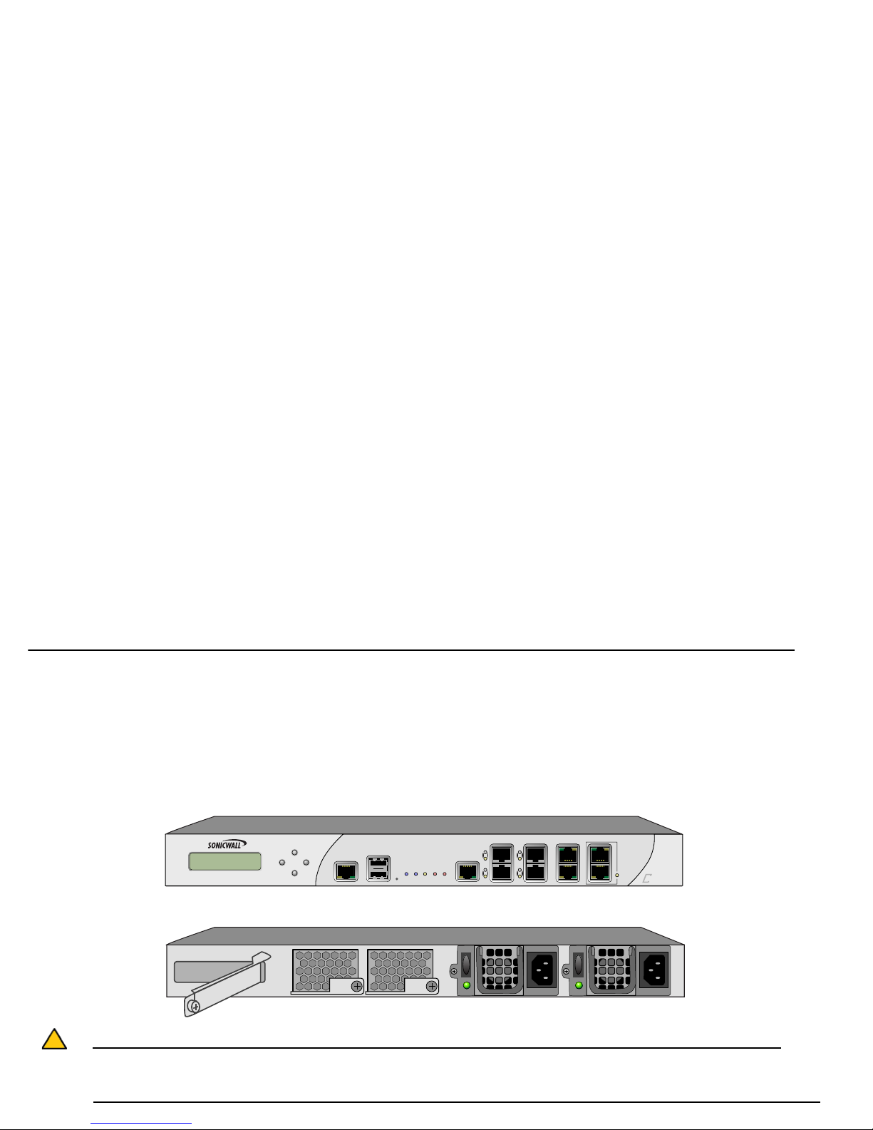
The Dell SonicWALL E-Class Network Security Appliance (NSA) E8500 is designed to be the most scalable, reliable, and best
performing multifunction appliance in its class.
This Getting Started Guide provides instructions for basic installation and configuration of the Dell SonicWALL NSA E8500.
Caution: Always observe proper safety and regulatory guidelines when removing administrator-service able parts from the Dell
SonicWALL NSA E8500. Proper guidelines can be found in Product Safety and Regulatory Information, on page 68 of this
guide.
E8500
Network Security Appliance
I
o
I
o
Page 4

This Getting Started Guide contains the following sections:
Chapter 1 Sections Include
Pre-Configuration Tasks - page 6 • Check Package Contents - page 7
• Obtain Configuration Information - page 8
• The Front Panel - page 10
• The Back Panel - page 11
• Front Bezel Control Features - page 12
• LAN IP Configuration Example - page 16
Chapter 2 Sections Include
Registering Your Appliance - page 18 • Before You Register - page 19
• Creating a MySonicWALL Account - page 20
• Registering and Licensing Your Appliance on MySonicWALL - page 20
Chapter 3 Sections Include
Deployment Scenarios - page 24 • Selecting a Deployment Scenario - page 25
• Initial Setup - page 29
• Configuring a Stateful HA Pair - page 36
• Configuring L2 Bridge Mode - page 43
Page 5

Chapter 4 Sections Include
Additional Deployment Configuration - page 46 • An Introduction to Zones and Interfaces - page 47
• Creating a NAT Policy - page 48
• Enabling Security Services in SonicOS - page 51
• Applying Security Services to Zones - page 52
• Troubleshooting Diagnostic Tools - page 52
Chapter 5 Sections Include
Support and Training Options - page 54 • Customer Support - page 55
• Knowledge Portal - page 55
• User Forums - page 56
• Training - page 57
• Related Documentation - page 58
• Dynamic Tooltips - page 59
• Dell SonicWALL Live Product Demos - page 59
• Dell SonicWALL Secure Wireless Network Integrated Solutions Guide - page 60
Chapter 6 Sections Include
Rack Mounting Instructions - page 62 • Rack Mounting Instructions - page 63
Chapter 7 Sections Include
Product Safety and Regulatory Information -
page 68
• Safety and Regulatory Information - page 69
• Warranty Information - page 73
• Copyright Notice - page 73
Page 6

Pre-Configuration Tasks
In this Section:
This section provides pre-configuration information. Review this section before setting up your Dell SonicWALL NSA E8500.
• Check Package Contents - page 7
• Obtain Configuration Information - page 8
• The Front Panel - page 10
• The Back Panel - page 11
• Front Bezel Control Features - page 12
• LAN IP Configuration Example - page 16
1
Page 7

Check Package Contents
Before you begin the setup process, verify that your package contains the following items:
1. One Dell SonicWALL NSA E8500 appliance
2. One serial CLI cable
3. One Ethernet cable
4. Two power cords*
5. One Rack Mounting Kit
6. One Dell SonicWALL NSA E8500 Getting Started Guide
*The included power cord(s) are approved for use only in specific countries or regions. Before using a power cord, ve rify that it is rated and approved for use in you r location. The
power cords are for AC mains installation only. Field conversion DC power cable is diff erent, see Safet y and Regulatory Info rmation for more informat ion.
Missing Items? If any items are missing from your package, contact Dell SonicWALL Support:
Web: http://www.sonicwall.com/us/Support.html
Email: [email protected]
E8500
Network Security Appliance
1
3
4
2
5
7
6
Getting Started Guide
Dell SonicWALL E-Class NSA Appliances
NETWORK SECURITY
NSA E8500
(x2)
Page 8
Obtain Configuration Information
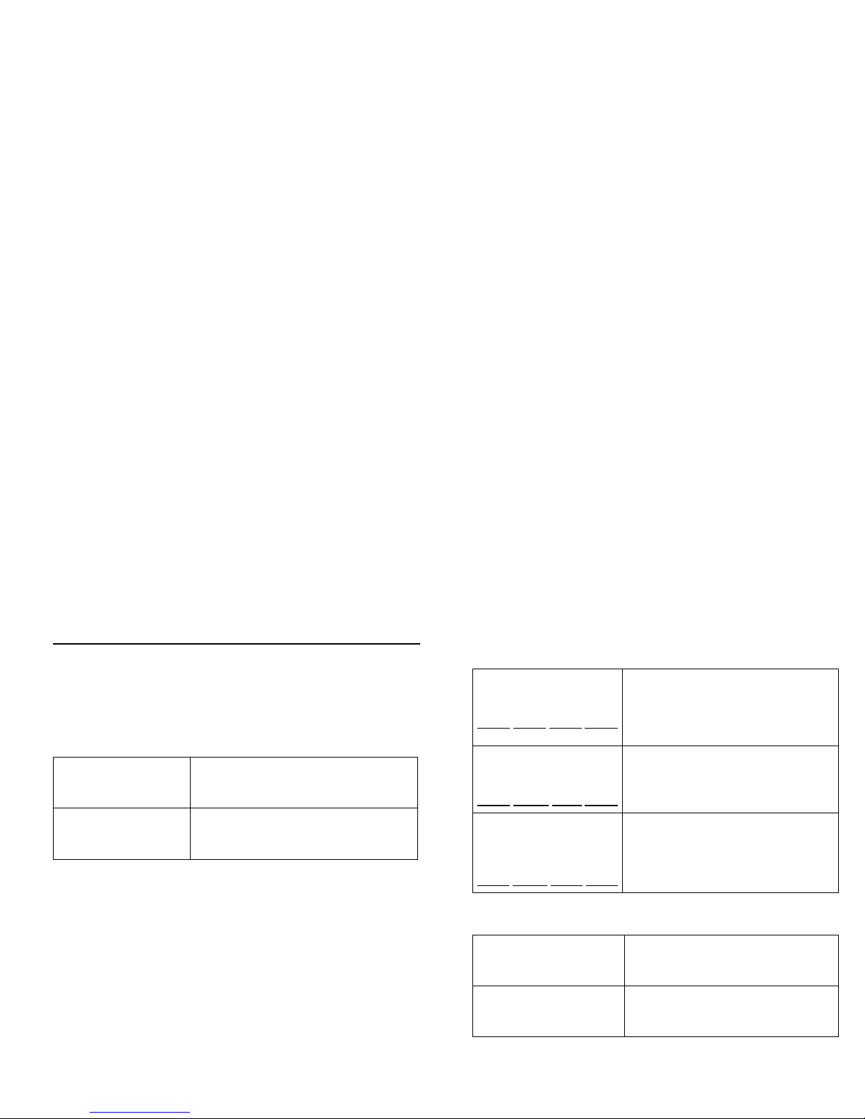
Please record and keep the following setup information:
Registration Information
Networking Information
Administrator Information
Serial Number:
Record the serial number found on the
bottom panel of your Dell SonicWALL
appliance.
Authentication Code:
Record the authentication code found on
the bottom panel of your Dell SonicWALL
appliance.
LAN IP Address:
. . .
Select a static IP address for your Dell
SonicWALL appliance that is within the
range of your local subnet. If you are
unsure, you can use the default IP
address (192.168.168.168).
Subnet Mask:
. . .
Record the subnet mask for the local
subnet where you are installing your Dell
SonicWALL appliance.
Ethernet WAN IP
Address:
. . .
Select a static IP address for your
Ethernet WAN. This setting only applies
if you are already using an ISP that
assigns a static IP address.
Admin Name:
Select an administrator account name.
(default is admin)
Admin Password:
Select an administrator password.
(default is password)
Page 9
Obtain Internet Service Provider (ISP)
Information
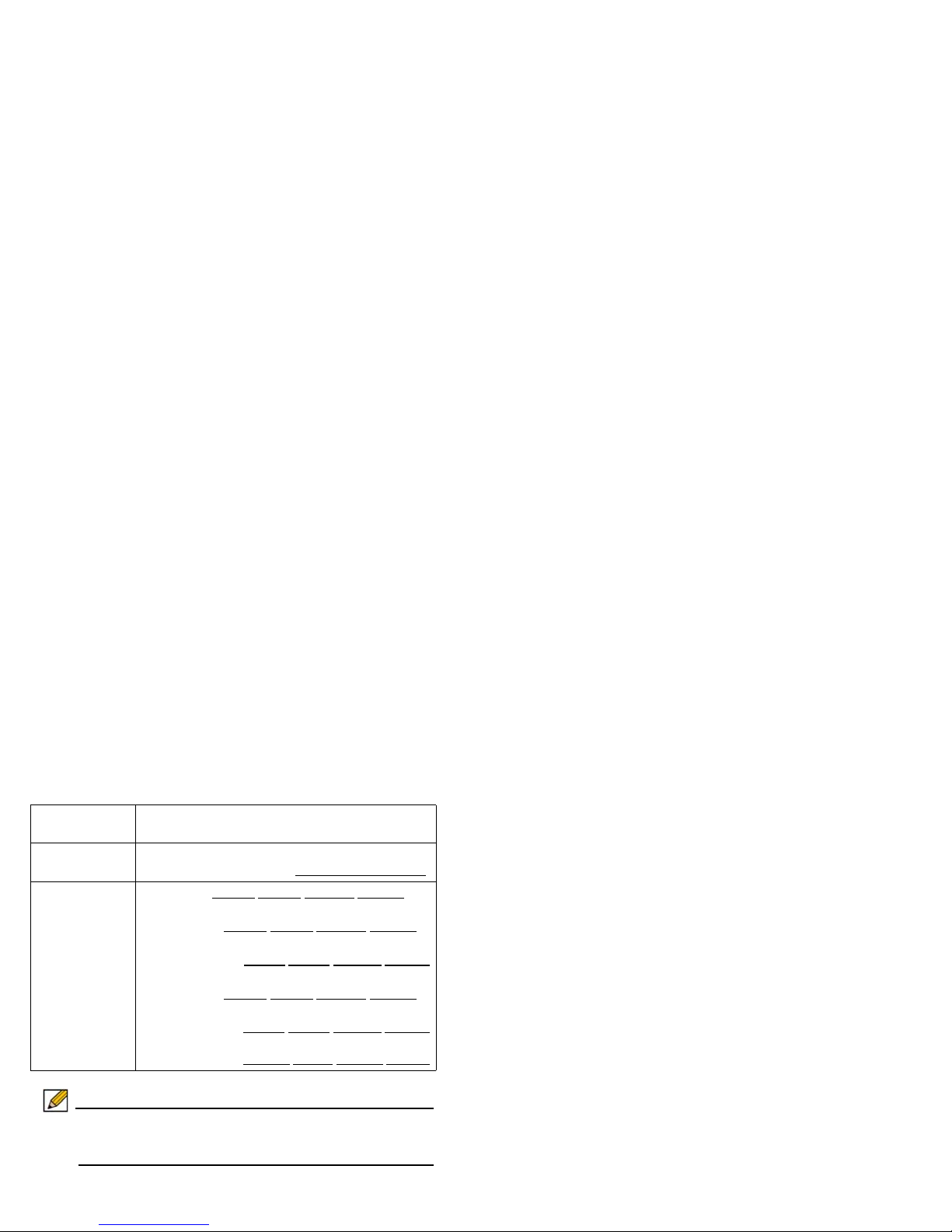
Record the following information about your current Internet
service:
Note: If you are not using one of the network configurations
above, refer to the SonicOS Administrator’s Guide:
www.sonicwall.com/us/support.html
If You connect
using
Please record
DHCP No information is usually required: Some providers
may require a Host name:
Static IP IP Address:
. . .
Subnet Mask: . . .
Default Gateway: . . .
Primary DNS: . . .
DNS 2 (optional): . . .
DNS 3 (optional): . . .
Page 10

The Front Panel
E8500
Network Security Appliance
LCD Screen
Control Buttons
Console Port
USB Ports (2)
Reset Button
LED Indicators (left to right)
HA Port
X4-X7 (SFP)
X0-X3 (Copper)
Bypass Status LED
Access the SonicOS Command Line Interface
(CLI) via the DB9 -> RJ45 cable
For future feature extensions
Press and hold for several seconds to
manually reset the appliance
High speed Gigabit Ethernet ports
Lit: Indicates when fail to wire bypass
mode is armed
Power (2): Blue: Indicates power supplies are operating correctly,
Yellow: Indicates an unconnected power supply or failure
Test: Quick blinking: Initializing, Slow blinking: SafeMode
Navigate the LCD screen
Interface to display status, make
configuration changes, restart the
appliance or boot into SafeMode
Hot-pluggable “small form-factor
pluggable transceiver” interfaces
for high speed fiber or copper
Ethernet communication
High Availability
primary/secondary
Gigabit Ethernet port
Page 11

The Back Panel
Warning: Potential Hazard from Fan
This manual contains specific warning and caution statements where they apply. Please read th e Safety Instructions before
use! See the Product Safety and Regulatory Information, on page 68.
I
o
I
o
Expansion Bay
Fans (2)
Power Supplies (2)
For SonicWall approved
expansion modules
Dual auto-throttling fans for system
temperature control
Dual power supplies for redundant AC power and added reliability
Field conversion is available to convert to DC mains
DC power supplies use different input connector and power cables
Page 12

Front Bezel Control Features
The Dell SonicWALL NSA E8500 is equipped with a front panel
bezel interface that allows an administrator to customize certain
aspects of the appliance or simply monitor its status without
having to log into it through a separate terminal.
Note: Using the front bezel for configuration purposes prior to
completing initial setup will bypass the Setup Wizard’s
automatic launch at startup.
LCD Control Buttons
The LCD interface is controlled by a D-pad, consisting of four
buttons: up, down, left, right. The table below describes the
functions of the buttons:
Icon Feature Description
LCD Screen Displays the front panel bezel interface
which can be used to display status
information, perform basic
configurations, restart the appliance or
boot the appliance in SafeMode.
Control Buttons Up, Down, Left and Right buttons,
used to navigate the LCD menu system.
.ETWORK3ECURITY!PPLIANCE
"
!
%
$
#
Network Security Appliance
B
A
C
E
Button Navigation Features
Up/Down Selects options and navigates up and down
lists.
Left Cancels changes and returns to the previous
menu.
Right Confirms choices and enters menus. Also sets
the appliance to screen-saver mode when used
from the main menu.
Page 13
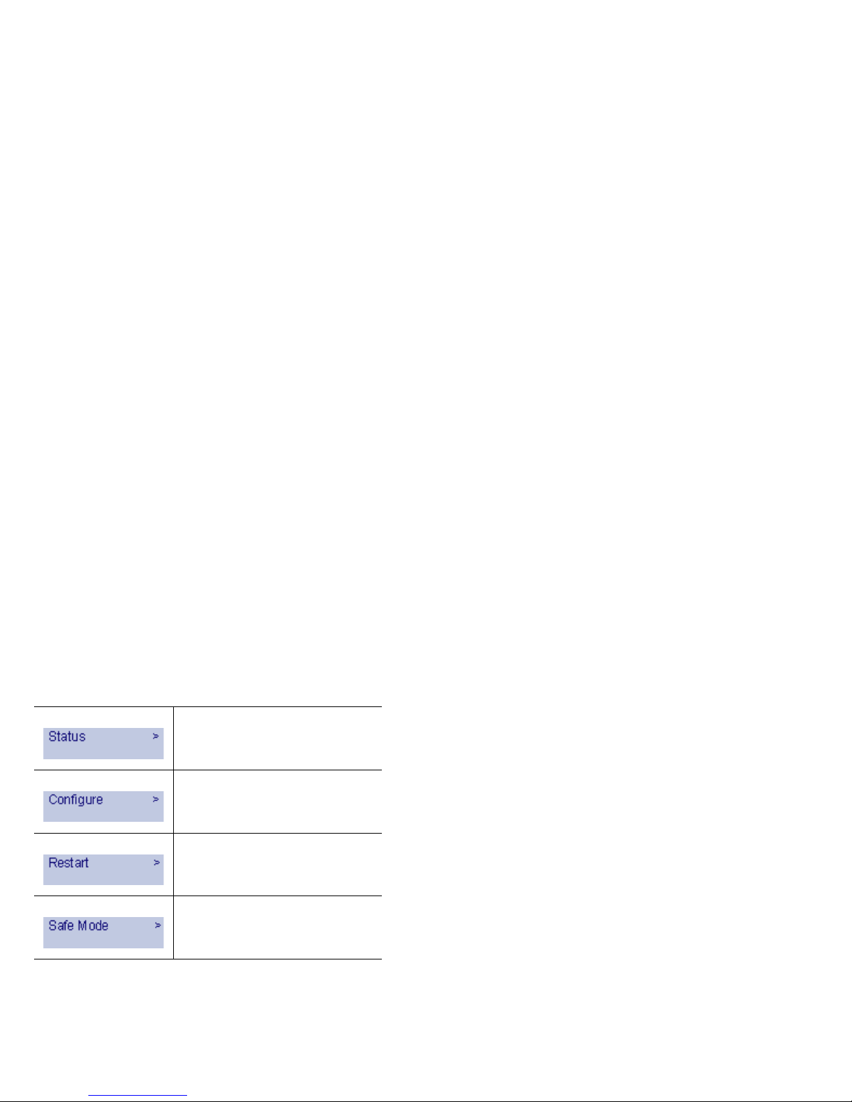
Main Menu
Upon booting the LCD display will initially show the Main Menu.
The menu is made up of four options:
Use the Up and Down button to select the menu you wish to
enter and click the Right button to enter it.
Status
The Status menu allows you to view specific aspects of the
appliance. Once selected, the LCD displays the Status List.
This list is navigated using the Up and Down buttons. Status
options available include:
• Appliance serial number
• Firmware / ROM versions
• Appliance name
• Date and Time
•Uptime
• CPU statistical readings
• Current number of connections
• Interface (X0, X1) network settings
• Interface (X0, X1) data transfer statistics
The X1 DNS1-3 entries will only be displayed if they have been
set from the Configure menu. If their value is still 0.0.0.0
(default value), they will not appear in the Status List.
Contains basic status values including
system resources, connections and port
configuration values.
Allows configuration of basic system
values including X0 (LAN) and X1
(WAN) port configuration. Requires
system pin for access, default: 76642.
Provides the ability to restart the
appliance. Requires system PIN for
access.
Provides the ability to restart and boot
the appliance into SafeMode. Requires
system PIN for access.
Page 14

Configure
The Configure Menu allows you to configure specific aspects of
the appliance. Once selected, the LCD will display a PIN
request.
Note: The Default PIN is 76642. This number spells SONIC
on a phone keypad. The PIN number can be changed
from the System > Administration page.
All numbers are inputted using the 4 buttons. Select the
individual digit field using the Left and Right button and select
the desired number using the Up and Down Button. Digits
increase incrementally from 0 to 9. Press the Right button to
confirm your PIN and enter the Configuration Menu.
The appliance allows the user to navigate in and out of the
Configuration Menu without having to re-enter the PIN.
However, once the appliance enters Screen-Saver Mode,
whether from the 6 second time out or from pressing the Left
button from the Main Menu, the PIN number must be re-entered
again to access the Configuration Menu.
After entering a new value for a setting in the configuration
menu, you are asked if you want to commit changes. Using the
4-way D-pad, press the Right button for yes or the Left button
for no.
If you choose yes, the screen notifies you that the settings are
updated.
Configuration Options
This option allows you to configure network port settings for the
appliance. Once selected, the LCD displays a list of
configurable options. Status options available include:
• X0 IP and subnet
• X1 Mode
• X1 IP and subnet
• X1 Gateway
• X1 DNS settings (3 available)
• Restore defaults
The X1 Mode can be set to Static (default option) or to DHCP. If
DHCP is selected, manual configuration options are not shown
for X1 IP, subnet, gateway and DNS.
Page 15

The Restore Defaults option will reset the appliance to default
factory settings. If selected it will prompt for confirmation twice
before restoring defaults.
If an option is selected but not modified, the appliance will
display a message stating that no changes were made and will
return the user to the edit value screen. If a change was made,
it will prompt the user for confirmation before effecting the
change.
Restart
This option allows you to safely restart without resorting to
power cycling the appliance. Once selected, the LCD will
display a confirmation prompt. Select Y for yes and press the
Right button to confirm. The appliance will reboot.
SafeMode
This option will set the appliance to SafeMode. Once selected,
the LCD will display a confirmation prompt. Select Y for yes and
press the Right button to confirm. The appliance will change to
SafeMode. Once SafeMode is enabled, the Dell SonicWALL
NSA E8500 must be controlled from the Web management
interface.
Screen-Saver
If no button is pressed for over 60 seconds, or if the Left button
is pressed from the Main Menu, the appliance will enter ScreenSaver mode. In this mode, the Status List will cycle, displaying
every entry for a few seconds.
If the Up or Down button is pressed while in Screen-Saver
mode, the appliance will display the adjacent status entry.
To exit Screen-Saver mode, press the Right button.
Page 16
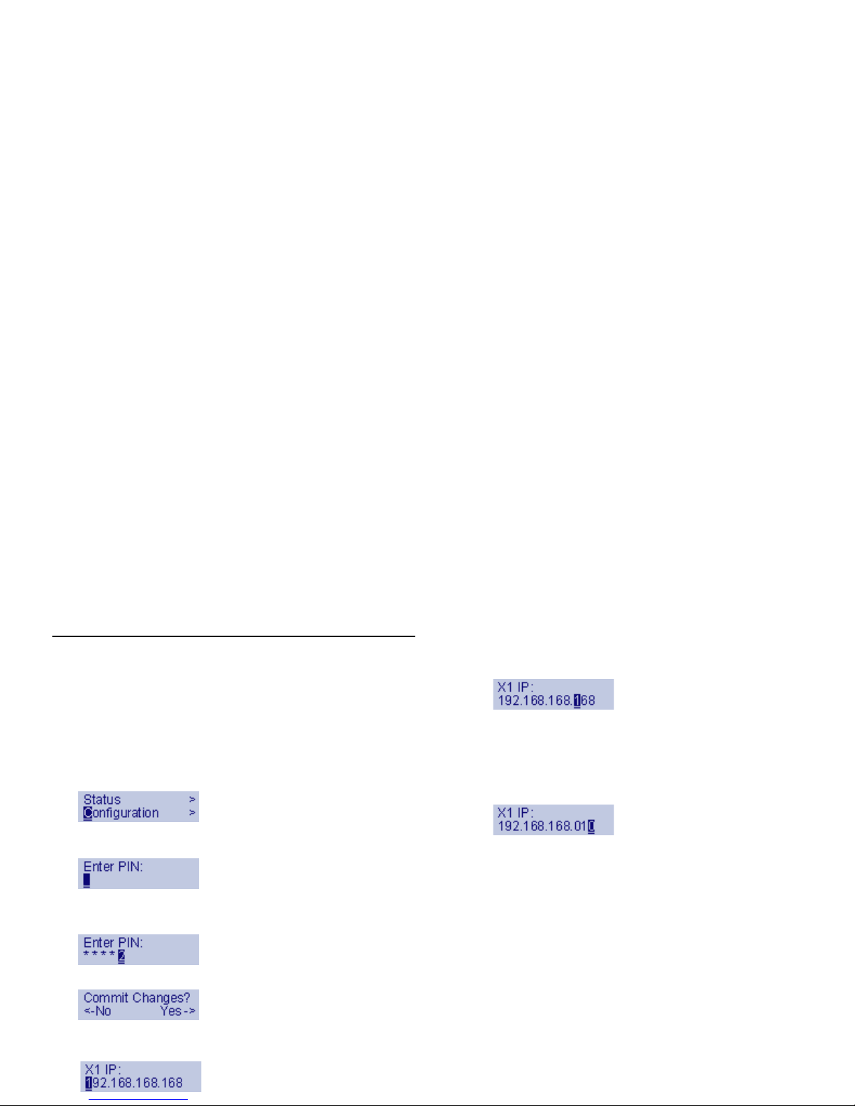
LAN IP Configuration Example
The Dell SonicWALL NSA E8500 is assigned the default LAN IP
of 192.168.168.168. The following example provides steps for
changing the default IP address to 192.168.168.10.
1. Press Right to exit screen-saver mode if not at the root
menu.
2. Press Down to select the Configuration entry.
3. Press Right to enter Configuration Mode.
4. Input PIN (76642 by default; SONIC on a phone keypad.)
5. Press Up or Down until the cursor displays 7, press Right.
6. Continue this process until all of the numbers are entered.
7. Press Right to commit changes.
8. Press Down until X1 IP is selected (four times).
9. Press Right to configure X1 IP.
10. Edit X1 IP:
11. Press Right ten times to select the tenth digit.
12. Press UP or Down until the cursor displays 0.
13. Press Right once to select the next digit.
14. Press UP or Down until the cursor displays 1.
15. Press Right once to select the next digit.
16. Press Up or Down until the cursor displays 0.
17. Press Right to finish editing the X1 IP.
18. Press Right again to confirm changes.
Page 17

Page 18

Registering Your Appliance
In this Section:
This section provides instructions for registering your Dell SonicWALL NSA E8500.
• Before You Register - page 19
• Creating a MySonicWALL Account - page 20
• Registering and Licensing Your Appliance on MySonicWALL - page 20
• Licensing Security Services and Software - page 21
• Registering a Secondary Appliance - page 22
Note: Registration is an important part of the setup process and is necessary in order to receive the benefits of Dell SonicWALL security
services, firmware updates, and technical support.
2
Page 19

Before You Register
You need a MySonicWALL account to register the Dell
SonicWALL NSA E8500. You can create a new MySonicWALL
account on www.sonicwall.com or directly from the Dell
SonicWALL management interface. This section describes how
to create an account by using the Web site.
You can use MySonicWALL to register your Dell SonicWALL
appliance and activate or purchase licenses for Security
Services, Analyzer Reporting and other services, support, or
software before you even connect your device. This allows you
to prepare for your deployment before making any changes to
your existing network.
For a High Availability configuration, you must use
MySonicWALL to associate a secondary unit that can share the
Security Services licenses with your primary Dell SonicWALL
appliance.
Note: Your Dell SonicWALL NSA E8500 does not need to be
powered on during account creation or during the
MySonicWALL registration and licensing process.
Note: After registering a new Dell SonicWALL appliance on
MySonicWALL, you must also register the appliance
from the SonicOS management interface. This allows
the unit to synchronize with the Dell SonicWALL
License Server and to share licenses with the
associated appliance, if any. See Accessing the
Management Interface, on page 31.
Page 20

Creating a MySonicWALL Account
To create a MySonicWALL account, perform the following steps:
1. In your browser, navigate to:
www.mysonicwall.com
2. In the login screen, click the Register Now link If you are
not a registered user.
3. Complete the Registration form and then click Register.
4. Verify that the information is correct and then click Submit.
5. In the screen confirming that your account was created,
click Continue.
Registering and Licensing Your
Appliance on MySonicWALL
This section contains the following subsections:
• Product Registration - page20
• Licensing Security Services and Software - page 21
• Registering a Secondary Appliance - page 22
• Registration Next S t eps - page 23
Product Registration
You must register your Dell SonicWALL NSA E8500 on
MySonicWALL to enable full functionality.
1. Login to your MySonicWALL account. If you do not have an
account, you can create one at:
www.mysonicwall.com
2. On the main page, in the Register A Product field, type the
appliance serial number and then click Next.
3. On the My Products page, under Add New Product, type
the friendly name for the appliance, select the Product
Group if any, type the authentication code into the
appropriate text boxes, and then click Register.
4. On the Product Survey page, fill in the requested
information and then click Continue.
Page 21

Licensing Security Services and Software
The Service Management - Associated Products page in
MySonicWALL lists security services, support options, and
software such as Analyzer that you can purchase or try with a
free trial. For details, click the Info button. Y our current licenses
are indicated in the Status column with either a license key or
an expiration date. Y ou can purchase additional services now or
at a later time.
The following products and services are available for the Dell
SonicWALL NSA E8500:
• Service Bundles:
• Client/Server Anti-Virus Suite
• Comprehensive Gateway Security Suite
• Gateway Services:
• Gateway AV / Anti-Spyware/Intrusion Prevention Service
/ Application Firewall
• Content Filtering: Premium Edition
• Stateful High Availability
• Active/Active High Availability
• Application Firewall
• Comprehensive Anti-Spam (CASS)
• Desktop and Server Software:
• Enforced Client Anti-Virus and Anti-S pyware
• Global VPN Client
• Global VPN Client Enterprise
• VPN Policy Upgrade (for site-to-site VPN)
• SSL-VPN
• Virtual Assist
• Global Management System
• Analyzer
• Support Services:
• Dynamic Support 24x7
• Software and Firmware Updates
• Consulting Services:
• Implementation Service
• GMS Preventive Maintenance Service
To manage your licenses, perform the following tasks:
1. In the MySonicWALL Service Management - Associated
Products page, check the Applicable Services table for
services that your Dell SonicWALL appliance is already
licensed for. Your initial purchase may have included
security services or other software bundled with the
appliance. These licenses are enabled on MySonicWALL
when the Dell SonicWALL appliance is delivered to you.
2. If you purchased a service subscription or upgrade from a
sales representative separately , you will have an
Activation Key for the product. This key is emailed to you
after online purchases, or is on the front of the certificate
that was included with your purchase. Locate the product
on the Services Management page and click Enter Key in
that row.
Page 22

3. In the Activate Service page, type or paste your key into the
Activation Key field and then click Submit. Depending on
the product, you will see an Expire date or a license key
string in the Status column when you return to the Service
Management page.
4. To license a product of service, do one of the following:
• To try a Free Trial of a service, click Try in the Service
Management page. A 30-day free trial is immediately
activated. The Status page displays relevant information
including the activation status, expiration date, number of
licenses, and links to installation instructions or ot he r
documentation. The Service Management page is also
updated to show the status of the free trial.
• To purchase a product or service, click Buy Now.
5. In the Buy Service page, type the number of licenses you
want in the Quantity column for either the 1 year, 2 year , or
3 year license row and then click Add to Cart.
6. In the Checkout page, follow the instructions to complete
your purchase.
The MySonicWALL server will generate a license key for the
product. The key is added to the license keyset. You can use
the license keyset to manually apply all active licenses to your
Dell SonicWALL appliance.
Registering a Secondary Appliance
To ensure that your network stays protected if your Dell
SonicWALL appliance has an unexpected failure, you can
associate a second appliance with the first in a high availability
(HA) pair. You can associate the two appliances as part of the
registration process on MySonicWALL. The second appliance
will automatically share the Security Services licenses of the
primary appliance.
T o register a second appliance and associate it with the primary ,
perform the following steps:
1. Login to your MySonicWALL account.
2. On the main page, in the Register A Product field, type the
appliance serial number and then click Next.
3. On the My Products page, under Add New Product, type
the friendly name for the appliance, select the Product
Group if any, type the authentication code into the
appropriate text boxes, and then click Register.
4. On the Product Survey page, fill in the requested
information and then click Continue. The Create
Association Page is displayed.
Page 23

5. On the Create Association Page, click the radio button to
select the primary unit for this association, and then click
Continue. The screen only displays units that are not
already associated with other appliances.
6. On the Service Management - Associated Products page,
scroll down to the Associated Products section to verify
that your product registered successfully. You should see
the HA Primary unit listed in the Parent Product section, as
well as a Status value of 0 in the Associ ated Products /
Child Product Type section.
To return to the Service Management - Associated Products
page, click the serial number link for this appliance.
Registration Next Steps
Yo ur Dell SonicWALL NSA E8500 or E8500 HA Pair is now
registered and licensed on MySonicWALL. To complete the
registration process in SonicOS and for more information, see:
• Accessing the Management Interface - page 31
• Activating Licenses in SonicOS - page 33
• Enabling Security Services in SonicOS - page 51
• Applying Security Services to Zones - page 52
Page 24

Deployment Scenarios
In this Section:
This section provides detailed overviews of advanced deployment scenarios as well as configuration instructions for connecting your Dell
SonicWALL NSA E8500.
• Selecting a Deployment Scenario - page 25
• Scenario A: NAT/Route Mode Gateway - page 26
• Scenario B: State Sync Pair in NAT/Route Mode - page 27
• Scenario C: L2 Bridge Mode - page 28
• Initial Setup - page 29
• Con fi gu r i ng a Stateful HA Pair - page 36
• Configuring L2 Bridge Mode - page 43
Note: Before completing this section, fill out the information in the Obtain Configuration Information section, on page 8. You will need to
enter this information during the Setup Wizard.
3
Page 25
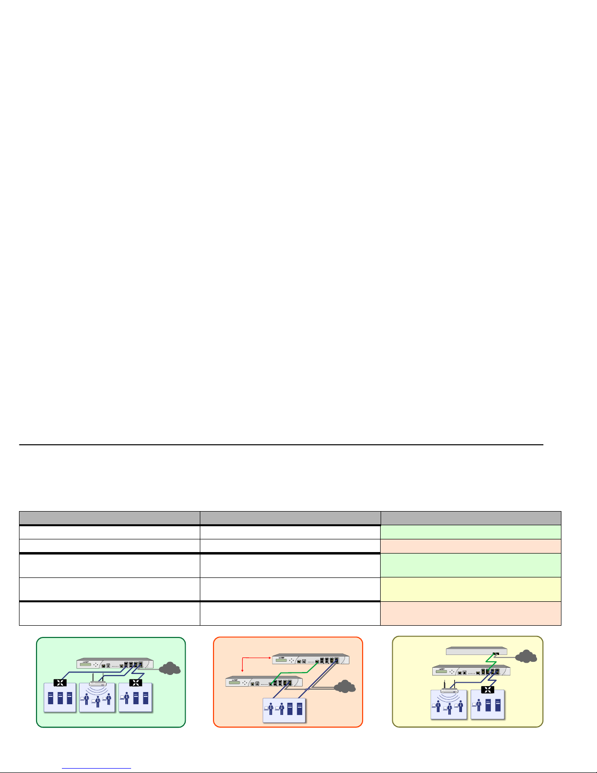
Selecting a Deployment Scenario
Before continuing, select a deployment scenario that best fits your network scheme. Reference the table below and the diagrams on the
following pages for help in choosing a scenario.
• Scenario A: NAT/Route Mode Gateway - page 26
• Scenario B: State Sync Pair in NAT/Route Mode - page27
• Scenario C: L2 Bridge Mode - page 28
Current Gateway Configuration New Gateway Configuration Use Scenario
No gateway appliance A Single NSA appliance as a primary gateway.
A - NAT/Route Mode Gateway
A Pair of NSA appliances for high availability.
B - NAT with State Sync Pair
Existing Internet gateway appliance An NSA appliance as replacement for an
existing gateway appliance.
A - NAT/Route Mode Gateway
An NSA appliance in addition to an existing
gateway appliance.
C - L2 Bridge Mode
Existing Dell SonicWALL gateway appliance An NSA appliance in addition to an existing Dell
SonicWALL gateway appliance.
B - NAT with State Sync Pair
E8500
Network Security Appliance
SonicPoint
A
E8500
Network Security Appliance
E8500
Network Security Appliance
B
E8500
Network Security Appliance
SonicPoint
C
Page 26
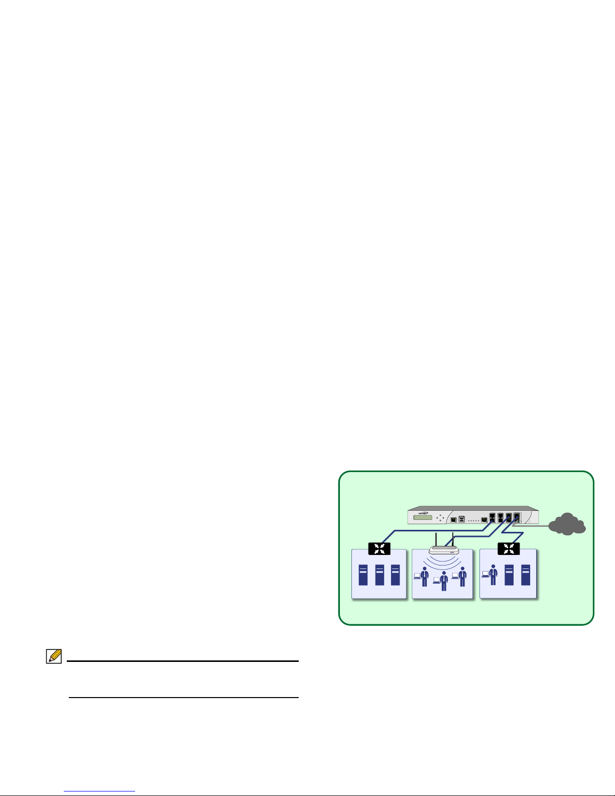
Scenario A: NAT/Route Mode Gateway
For new network installations or installations where the Dell
SonicWALL NSA E8500 is replacing the existing network
gateway .
In this scenario, the NSA E8500 is configured in NAT/Route
mode to operate as a single network gateway. Two Internet
sources may be routed through the Dell SonicWALL appliance
for load balancing and failover purposes. Because only a single
Dell SonicWALL appliance is deployed, the added benefits of
high availability with a stateful synchronized pair are not
available.
To set up this scenario, follow the steps covered in:
• Initial Setup - page 29
• Additional Deployment Configuration - page 46
Note: Be sure to follow the steps in the Initial Setup section,
on page 29 before completing Additional Deployment
Configurations.
LAN Zone
DMZ Zone
WLAN Zone
E8500
Network Security Appliance
SonicPoint
SonicWALL NSA E-Class
Internet
ISP 1
A
Page 27
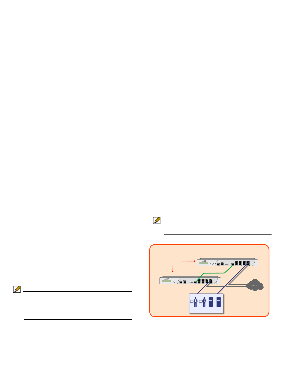
Scenario B: State Sync Pair in NAT/Route
Mode
For network installations with two Dell SonicWALL NSA E8500
appliances configured as a stateful synchronized pair for
redundant high-availability networking.
In this scenario, one NSA E8500 operates as the primary
gateway device and the other NSA E8500 is in passive mode.
All network connection information is synchronized between the
two devices so that the secondary appliance can seamlessly
switch to active mode without dropping connections if the
primary device loses connectivity.
Note: Active/Active pair functionality is also available for
high-availability deployments. For more information on
the benefits and setup instruction for Active/Active pair,
see the “SonicOS Active/Active Feature Module” at:
www.sonicwall.com/us/support.html
To set up this scenario, follow the steps covered in:
• Initial Setup - page 29
• Con fi gu r i ng a Stateful HA Pair - page 36
• Additional Deployment Configuration - page 46
Note: Follow the steps in the Initial Setup section, on page 29
before completing State Sync Pair setup.
E8500
Network Security Appliance
E8500
Network Security Appliance
B
SonicWALL
HA/Failover Pair
SonicWALL NSA E-Class 1
SonicWALL NSA E-Class 2
HA Link
Local Network
Page 28
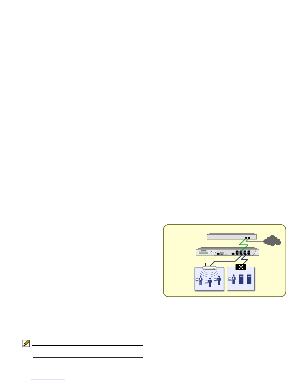
Scenario C: L2 Bridge Mode
For network installations where the Dell SonicWALL NSA
E8500 is running in tandem with an existing network gateway.
In this scenario, the original gateway is maintained. The NSA
E8500 is integrated seamlessly into the existing network,
providing the benefits of deep packet inspection and
comprehensive security services on all network traffic.
L2 Bridge Mode employs a secure learning bridge architecture,
enabling it to pass and inspect traffic types that cannot be
handled by many other methods of transparent security
appliance integration. Using L2 Bridge Mode, a Dell SonicWALL
security appliance can be non-disruptively added to any
Ethernet network to provide in-line deep-packet inspection for
IPv4 TCP and UDP traffic.
To set up this scenario, follow the steps covered in:
• Initial Setup - page 29
• Configuring L2 Bridge Mode - page 43
• Additional Deployment Configuration - page 46
Note: Be sure to follow the steps in the Initial Setup section,
on page 29 before completing L2 Bridge Mode setup.
E8500
Network Security Appliance
SonicWALL NSA E-Class
SonicPoint
LAN Zone
Third Party Gateway
WLAN Zone
Internet or
LAN Segment 2
L2 Bridge Link
C
Page 29
Initial Setup
This section provides initial configuration instructions for
connecting your Dell SonicWALL NSA E8500. Follow these
steps if you are setting up Scenario A, B, or C.
This section contains the following sub-sections:
• System Requirements - page 29
• Connecting the WAN Port - page 29
• Connecting the LAN Port - page 30
• Applying Power - page 30
• Accessing the Management Interface - page 31
• Using the Setup Wizard - page 31
• Connecting to Your Network - page 32
• Testing Your Connection - page 32
• Activating Licenses in SonicOS - page 33
• Upgrading Firmware - page 33
System Requirements
Before you begin the setup process, check to verify that you
have:
• An Internet connection
• A Web browser supporting Java Script and HTTP uploads
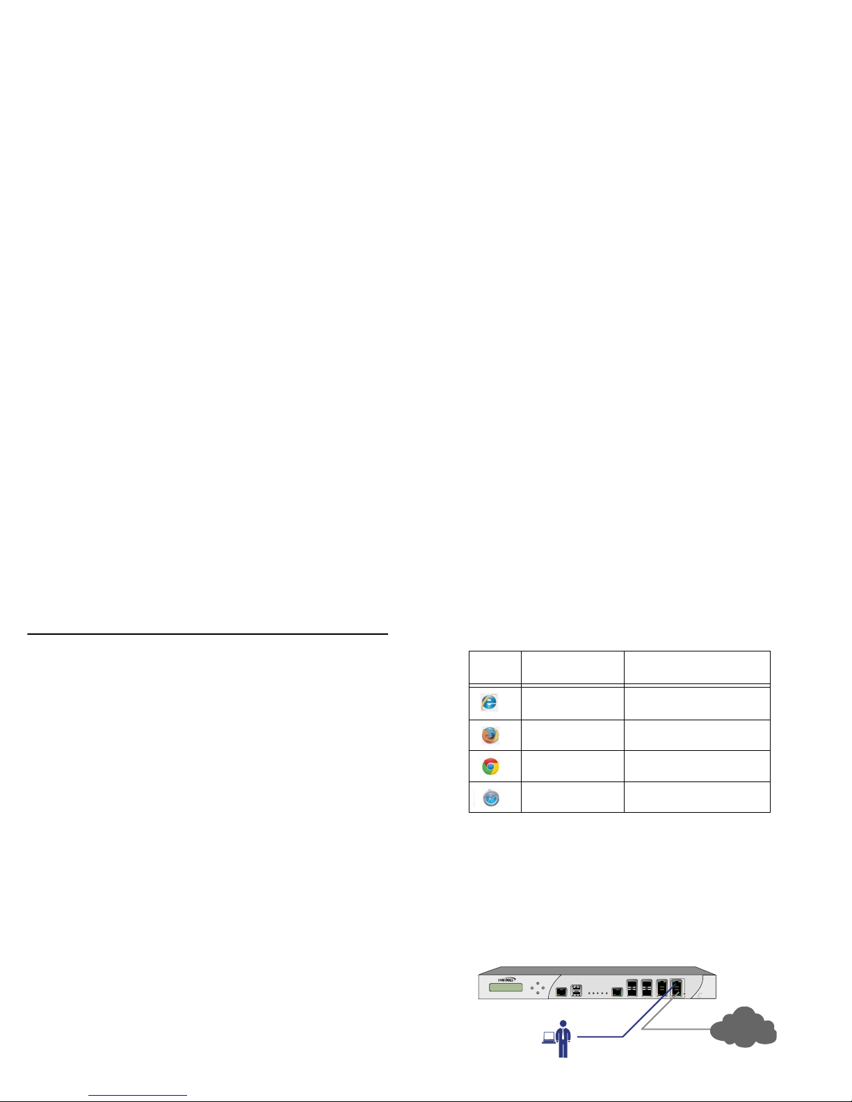
Connecting the WAN Port
1. Connect one end of an Ethernet cable to your Internet
connection.
2. Connect the other end of the cable to the X1 (WAN) port on
your NSA E8500.
Accepted
Browser
Browser Version
Number
Internet Explorer 8.0, 9.0, and 10.0 (do not
use compatibility mode)
Firefox 16.0 or higher
Chrome 18.0 or higher
Safari 5.0 or higher for MacOS
E8500
Network Security Appliance
Management
Station
SonicWALL NSA E8500
X0
X1
Internet
Page 30
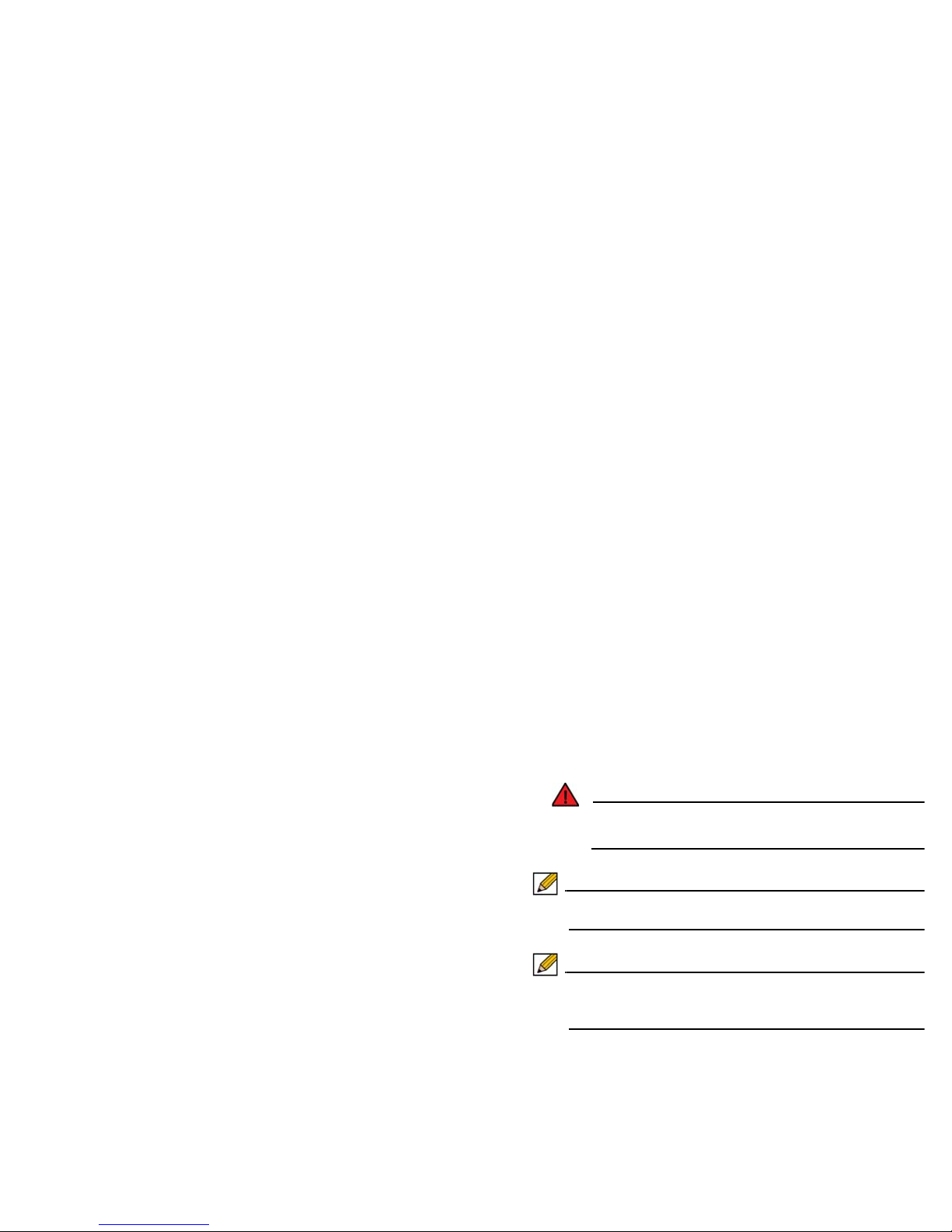
Connecting the LAN Port
1. Connect one end of the provided Ethernet cable to the
computer you are using to manage the NSA E8500.
2. Connect the other end of the cable to the X0 port on your
NSA E8500.
The Link LED above the X0 (LAN) port will light up in green
or amber depending on the link throughput speed,
indicating an active connection:
• Amber indicates 1 Gbps
• Green indicates 100 Mbps
• Unlit while the right (activity) LED is illuminated indicates
10 Mbps
Applying Power
1. Connect the power cords from the NSA E8500 into
appropriate power outlets. For further information on power
requirements, see the Safety and Regulatory Information
section, on page 69 of this document.
2. Turn on both power switches on the rear of the appliance
next to the power cords.
The Power LEDs on the front panel light up blue when you plug
in the Dell SonicWALL NSA E8500. The Alarm LED may light
up and the Test LED will light up and may blink while the
appliance performs a series of diagnostic tests.
When the Power LEDs are lit and the Test LED is no longer lit,
the Dell SonicWALL NSA E8500 is ready for configuration. This
typically occurs within a few minutes of applying power to the
appliance.
Warning: When disconnecting power, be sure to remove both
power cords from the unit.
Note: Only one power supply is required for the appliance to
operate.
Note: If the Test or Alarm LEDs remain lit after the NSA
E8500 has booted, restart the appliance by cycling
power.
Page 31

Accessing the Management Interface
The computer you use to manage the Dell SonicWALL NSA
E8500 must be set up to accept a dynamic IP address, or it
must have an unused IP address on the 192.168.168.x/24
subnet, such as 192.168.168.20.
To access the SonicOS Web-based management interface:
1. Start your W e b browser.
2. Disable pop-up blocking software or add the management
IP address http://192.168.168.168 to your pop-up blocker’s
allow list.
3. Enter http://192.168.168.168 (the default LAN
management IP address) in the Location or Address field.
4. The Dell SonicWALL Setup Wizard launches and guides
you through the configuration and setup of your Dell
SonicWALL NSA E8500.
Note: The Setup Wizard launches automatically only upon
initial loading of the NSA E8500 management interface.
5. Follow the on-screen prompts to complete the Setup
Wizard.
Depending on the changes made during your setup
configuration, the NSA E8500 appliance may restart.
Using the Setup Wizard
If you cannot connect to the Dell SonicWALL NSA E8500 or the
Setup Wizard does not display, verify the following
configurations:
• Did you correctly enter the Dell SonicWALL NSA E8500
management IP address in your Web browser?
• Are the Local Area Connection settings on your computer set
to use DHCP or set to a static IP address on the
192.168.168.x/24 subnet?
• Do you have the Ethernet cable connected to your computer
and to the X0 (LAN) port on your NSA E8500 appliance?
• Is the connector clip on your network cable properly seated in
the port of the security appliance?
• Some browsers may not launch the Setup Wizard
automatically. In this case:
• Log into the NSA E8500 using “admin” as the user name
and “password” as the password.
• Click the Wizards button on the System > St atus page.
• Select Setup Wizard and click Next to launch the Setup
Wizard.
• Some pop-up blockers may prevent the launch of the
Setup Wizard. You can temporarily disable your pop-up
blocker, or add the management IP address of your NSA
E8500 (192.168.168.168 by default) to your pop-up
blocker's allow list.
Page 32
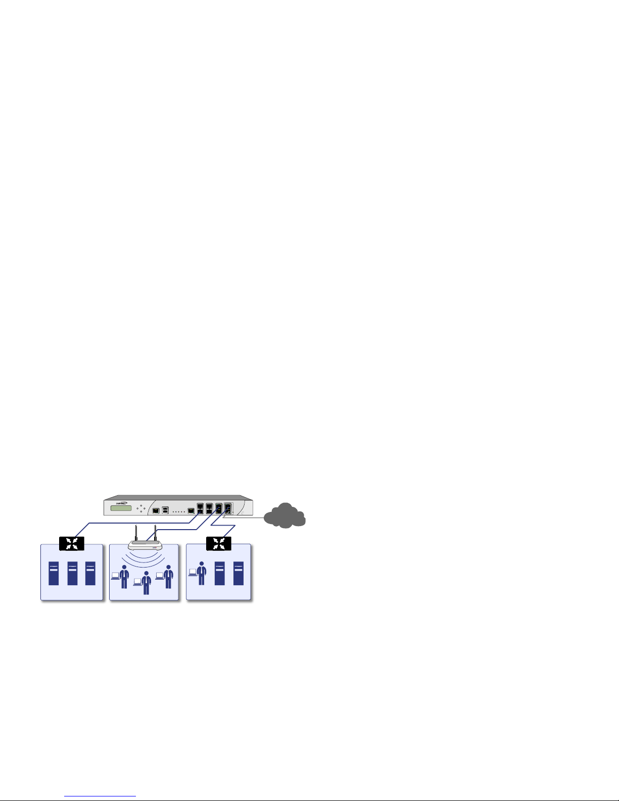
Connecting to Your Network
The Dell SonicWALL NSA E8500 ships with the internal DHCP
server active on the LAN port. However, if a DHCP server is
already active on your LAN, the NSA E8500 will disable its own
DHCP server to prevent conflicts.
As shown in the illustration on this page, ports X1 and X0 are
preconfigured as WAN and LAN respectively. The remaining
ports (X2-X7) can be configured to meet the needs of your
network. In the graphical example on this page, the zones are:
X1: WAN, X0: LAN, X2: WLAN, X7: DMZ.
The above example is only for reference, your own port to zone
assignments depend on your networking goals and needs.
Refer to the SonicOS Administrator’s Guide for more advanced
configuration deployments.
Testing Your Connection
1. After you exit the Setup Wizard, the login page reappears.
Log back into the Management Interface and verify your IP
and WAN connection.
2. Ping a site outside of your local network, such as:
www.sonicwall.com
3. Open another Web browser and navigate to:
www.sonicwall.com
If you can view the Dell SonicWALL home page, you have
configured your Dell SonicWALL NSA E8500 correctly.
If you cannot view the Dell SonicWALL home page, renew
your management station DHCP address.
4. If you still cannot view a Web page, try one of these
solutions:
• Restart your Management Station to accept new
network settings from the DHCP server in the Dell
SonicWALL security appliance.
• Restart your Internet Router to communicate with the
DHCP Client in the Dell SonicWALL security appliance.
E8500
Network Security Appliance
SonicPoint
LAN Zone
SonicWALL NSA E8500
DMZ Zone
WLAN Zone
X1
X0
X2
X7
Internet
Page 33

Activating Licenses in SonicOS
After completing the registration process in SonicOS, you must
perform the following tasks to activate your licenses and enable
your licensed services from within the SonicOS user interface:
• Activate licenses
• Enable security services
• Apply services to network zones
This section describes how to activate your licenses. For
instructions on how to enable security services and apply
services to network zones, see the following sections:
• Enabling Security Services in SonicOS - page 51
• Applying Security Services to Zones - page 52
To activate licensed services in SonicOS, you can enter the
license keyset manually, or you can synchronize all licenses at
once with MySonicWALL.
The Setup Wizard automatically synchronizes all licenses with
MySonicWALL if the appliance has Internet access during initial
setup. If initial setup is already complete, you can synchronize
licenses from the System > Licenses page.
Manual upgrade using the license keyset is useful when your
appliance is not connected to the Internet. The license keyset
includes all license keys for services or software enabled on
MySonicWALL. It is available on MySonicWALL at the top of the
Service Management page for your Dell SonicWALL appliance.
To activate licenses in SonicOS:
1. Navigate to the System > Licenses page.
2. Under Manage Security Services Online do one of the
following:
• Enter your MySonicWALL credentials, then click the
Synchronize button to synchronize licenses with
MySonicWALL.
• Paste the license keyset into the Manual Upgrade
Keyset field.
3. Click Submit.
Upgrading Firmware
The following procedures are for upgrading an existing
SonicOS image to a newer version:
• Obtaining the Latest Firmware - page 33
• Saving a Backup Copy of Your Preferences - page 34
• Upgrading the Firmware - page 34
• Using SafeMode to Upgrade Firmware - page 35
Obtaining the Latest Firmware
1. To obtain a new SonicOS firmware image file for your Dell
SonicWALL NSA E8500, connect to your MySonicWALL
account at:
www.mysonicwall.com
2. Copy the new SonicOS image file to a convenient location
on your management station.
Page 34

Saving a Backup Copy of Your Preferences
Before beginning the update process, make a system backup of
your Dell SonicWALL NSA E8500 appliance configuration
settings. The backup feature saves a copy of the curre n t
configuration settings on your Dell SonicWALL appliance,
protecting all your existing settings in the event that it becomes
necessary to return to a previous configuration state.
In addition to using the backup feature to save your current
configuration state to the Dell SonicWALL NSA E8500, you can
export the configuration preferences file to a directory on your
local management station. This file serves as an external
backup of the configuration preferences, and can be imported
back into the Dell SonicWALL appliance.
Perform the following procedures to save a backup of your
configuration settings and export them to a file on your local
management station:
1. On the System > Settings page, click Create Backup.
Your config uration preferences are saved. The System
Backup entry is displayed in the Firmware Management
table.
2. T o export your settings to a local file, click Export Settings.
A popup window displays the name of the saved file.
Upgrading the Firmware
Perform the following steps to upload new firmware to your Dell
SonicWALL NSA E8500 and use your current configuration
settings upon startup.
Note: The appliance must be properly registered before it can
be upgraded. Refer to the Registering and Licensing
Your Appliance on MySonicWALL section, on page 20
for more information.
1. Download the SonicOS firmware image file from
MySonicWALL and save it to a location on your local
computer.
2. On the System > Settings page, click Upload New
Firmware.
3. Browse to the location where you saved the SonicOS
firmware image file, select the file and click the Upload
button.
4. On the System > Settings page, click the Boot icon in the
row for Uploaded Firmware - New! or Uploaded
Firmware with Factory Default Settings - New!.
5. In the confirmation dialog box, click OK. The Dell
SonicWALL appliance restarts and then displays the login
page.
6. Enter your user name and password. Your new SonicOS
image version information is listed on the System >
Settings page.
Page 35

Using SafeMode to Upgrade Firmware
If you are unable to connect to the Dell SonicWALL NSA E8500
appliance’s management interface, you can restart the
appliance in SafeMode. The SafeMode feature allows you to
recover quickly from uncertain configuration states with a
simplified management interface that includes the same
settings available on the System > Settings page.
To use SafeMo de to upgrade firmware on the NSA E8500,
perform the following steps:
1. Connect your computer to the X0 port on the NSA E8500
appliance and configure your IP address with an address
on the 192.168.168.0/24 subnet, such as 192.168.168.20.
2. To configure the appliance in SafeMode, perform one of
the following methods:
• Use a narrow, straight object, like a straightened paper
clip or a toothpick, to press and hold the reset button on
the front of the security appliance for at least twenty
seconds. See The Front Panel section, on page 10 to
locate the reset button.
• Use the LCD control buttons on the front bezel to set the
appliance to SafeMode. Once selected, the LCD displays
a confirmation prompt. Select Y and press the Right
button to confirm. The NSA E8500 appliance changes to
SafeMode.
The Test light starts blinking when the NSA E8500
appliance has rebooted into SafeMode.
3. Point the Web browser on your computer to
192.168.168.168. The SafeMode management interface
displays.
4. If you have made any configuration changes to the security
appliance, select the Create Backup On Next Boot
checkbox to make a backup copy of your current settings.
Your settings will be saved when the appliance restarts.
5. Click Upload New Firmware, and then browse to the
location where you saved the SonicOS firmware image,
select the file and click the Upload button.
6. Select the boot icon in the row for one of the following:
• Uploaded Firmware - New!
Use this option to restart the appliance with your
current configuration settings.
• Uploaded Firmware with Factory Default Settings - New!
Use this option to restart the appliance with default
configuration settings.
7. In the confirmation dialog box, click OK to proceed.
8. After successfully booting the firmware, the login screen is
displayed. If you booted with factory default settings, enter
the default user name and password (admin / password) to
access the NSA E8500 management interface.
Page 36
Note: Use the table below to complete setup for your
scenario. Look for this “Next” icon to guide you to the
next section.
Configuring a Stateful HA Pair
This section provides instructions for configuring a pair of Dell
SonicWALL NSA E8500 appliances for high availability (HA).
This section is relevant to administrators following deployment
Scenario B.
This section contains the following sub-sections:
• Initial High Availability Setup - page 37
• Configuring High Availability - page 37
• Configuring Advanced HA Settings - page 38
• Configuring HA Monitoring Settings - page 39
• Synchronize Settings - page 40
• HA License Configuration Overview - page 41
• Associating Pre-Registered Appliances - page 42
If You Are Following
Scenario...
Proceed to Section:
A - NAT/Route Mode
Gateway
Additional Deployment Configuration
- page 46
B - NAT with State Sync
Pair
Configuring a Stateful HA Pair -
page 36
C - L2 Bridge Mode Configuring L2 Bridge Mode -
page 43
SonicWALL NSA E-Class 1
SonicWALL NSA E-Class 2
HA
HA
X0
X1
X1
X0
E5500
Network Security Appliance
E5500
Network Security Appliance
Local Network
SonicWALL
HA / Failover Pair
Internet
HA Link
Page 37

Initial High Availability Setup
Before you begin the configuration of HA on the Primary Dell
SonicWALL security appliance, perform the following setup:
• On the bottom panel of the secondary Dell SonicWALL
security appliance, locate the serial number and write the
number down. You need to enter this number in the High
Availability > Settings page.
• Verify that the primary and secondary Dell SonicWALL
security appliances are registered, running the same
SonicOS versions.
• Make sure the primary and secondary Dell SonicWALL
security appliances’ LAN, WAN and other interfaces are
properly configured for failover.
• Connect the HA ports on the primary and secondary Dell
SonicWALL appliances with a CAT6-rated crossover cable
(red crossover cable). The primary and secondary Dell
SonicWALL security appliances must have a dedicated
connection using the HA interface. Dell SonicWALL
recommends cross-connecting the two together using a CAT
6 crossover Ethernet cable, but a connection using a
dedicated 100Mbps hub/switch is also valid.
• Power up the primary Dell SonicWALL security appliance,
and then power up the secondary Dell SonicWALL security
appliance.
• Do not make any configuration changes to the primary’s HA
interface; the High Availability configuration in an upcoming
step takes care of this issue. When done, disconnect the
workstation.
Configuring High Availability
The first task in setting up HA after initial setup is configuring
the High Availability > Settings page on the primary Dell
SonicWALL security appliance. Once you configure HA on the
primary Dell SonicWALL security appliance, it communicates
the settings to the secondary Dell SonicWALL security
appliance.
T o configure HA on the primary appliance, perform the following
steps:
1. Navigate to the High Availability > Settings page.
2. Select the Enable High Availability checkbox.
3. Under SonicWALL Address Settings, type in the serial
number for the secondary Dell SonicWALL appliance.
You can find the serial number on the bottom of the Dell
SonicWALL security appliance, or in the System > Status
screen of the secondary unit. The serial number for the
primary Dell SonicWALL is automatically populated.
4. Click Apply to retain these settings.
Page 38

Configuring Advanced HA Settings
1. Navigate to the High Availability > Advanced page.
2. To configure Stateful HA, select Enable Stateful
Synchronization. A dialog box is displayed with
recommended settings for the Heartbeat Interval and
Probe Interval fields. The settings it shows are minimum
recommended values. Lower values may cause
unnecessary failovers, especially when the appliance is
under a heavy load. You can use higher values if your
SonicWALL handles a lot of network traffic. Click OK.
3. To cause the HA pair to change back to the original primary
unit when it becomes available after a failover, select the
Enable Preempt Mode checkbox.
4. T o backup the firmware and settings when you upgrade the
firmware version, select Generate/Overwrite Backup
Firmware and Settings When Upgrading Firmware.
5. Select the Enable Virtual MAC checkbox. Virtual MAC
allows the primary and secondary appliances to share a
single MAC address. This greatly simplifies the process of
updating network ARP tables and caches when a failover
occurs. Only the WAN switch that the two appliances are
connected to needs to be notified. All outside devices will
continue to route to the single shared MAC address.
6. Optionally adjust the Heartbeat Interval to control how
often the two units communicate. This timer is the length of
time between status checks. By default this timer is set to
5000 milliseconds, the minimum recommended value is
1000 milliseconds. Using a longer interval will result in the
appliance taking more time to detect when/if failures have
occurred. Less than this may cause unnecessary failovers,
especially when the appliance is under a heavy load.
7. Set the Probe Interval for the interval in seconds between
communication with upstream or downstream systems.
This timer controls the path monitoring speed. Path
monitoring sends pings to specified IP addresses to
monitor that the network critical path is still reachable. The
default is 20 seconds, and the allowed range is from 5 to
255 seconds. It is recommended that you set the interval
for at least 5 seconds. You can set the Probe IP
Address(es) on the High Availability > Monitoring
screen.
8. In the Probe Count text-field, enter the desired number of
consecutive probes before the appliance considers the
network critical path to be reachable or broken. The
minimum and default is 3 probes, and the maximum is 10.
9. Typically, Dell SonicWALL recommends leaving the
Failover Trigger Level (missed heart beats), Election
Delay Time (seconds), and Dynamic Route Hold-Down
Time fields to their default settings. These fields can be
tuned later as necessary for your specific network
environment.
•The Failover Trigger Level (missed heart beats) timer
is the number of heartbeats the appliance will miss before
failing over. By default, this time is set to 5 missed heart
beats.This timer is linked to the Heartbeat Interval timer –
for example, if you set the Heartbeat Interva l to 10
seconds, and the Failover Trigger Level timer to 5, it will
be 50 seconds before the appliance fails over.
Page 39
•The Election Delay Time can be used to specify an
amount of time the appliance will wait to consider an
interface up and stable before one of them takes the
primary role. This is useful when dealing with switch ports
that have a spanning-tree delay set
•The Dynamic Route Hold-Down Time setting is used
when a failover occurs on a HA pair that is using either
RIP or OSPF dynamic routing. When a failover occurs,
Dynamic Route Hold-Down Time is the number of
seconds the newly-active appliance keeps the dynamic
routes it had previously learned in its route table. During
this time, the newly-active appliance relearns the
dynamic routes in the network. When the Dynamic
Route Hold-Down Time duration expires, it deletes the
old routes and implements the new routes it has learned
from RIP or OSPF. The default value is 45 seconds. In
large or complex networks, a larger value may improve
network stability during a failover.
10. Click the Include Certificates/Keys checkbox to have the
appliances synchronize all certificates and keys.
11. Click Synchronize Settings to synchronize the settings
between the primary and secondary appliances.
12. Click Synchronize Firmware if you previously uploaded
new firmware to your Primary unit while the Secondary unit
was offline, and it is now online and ready to upgrade to the
new firmware. Synchronize Firmware is typically used
after taking your Secondary appliance offline while you test
a new firmware version on the Primary unit before
upgrading both units to it.
13. Click Accept to retain the settings on this screen.
Configuring HA Monitoring Settings
After configuring the HA settings, you need to configure the
Monitoring settings for the LAN or WAN.This includes
configuring unique IP addresses for each appliance in the
Stateful HA pair. You will need to log into the appliances using
these IP addresses in order to complete the registration
process from within SonicOS, which will allow license sharing
and synchronization.
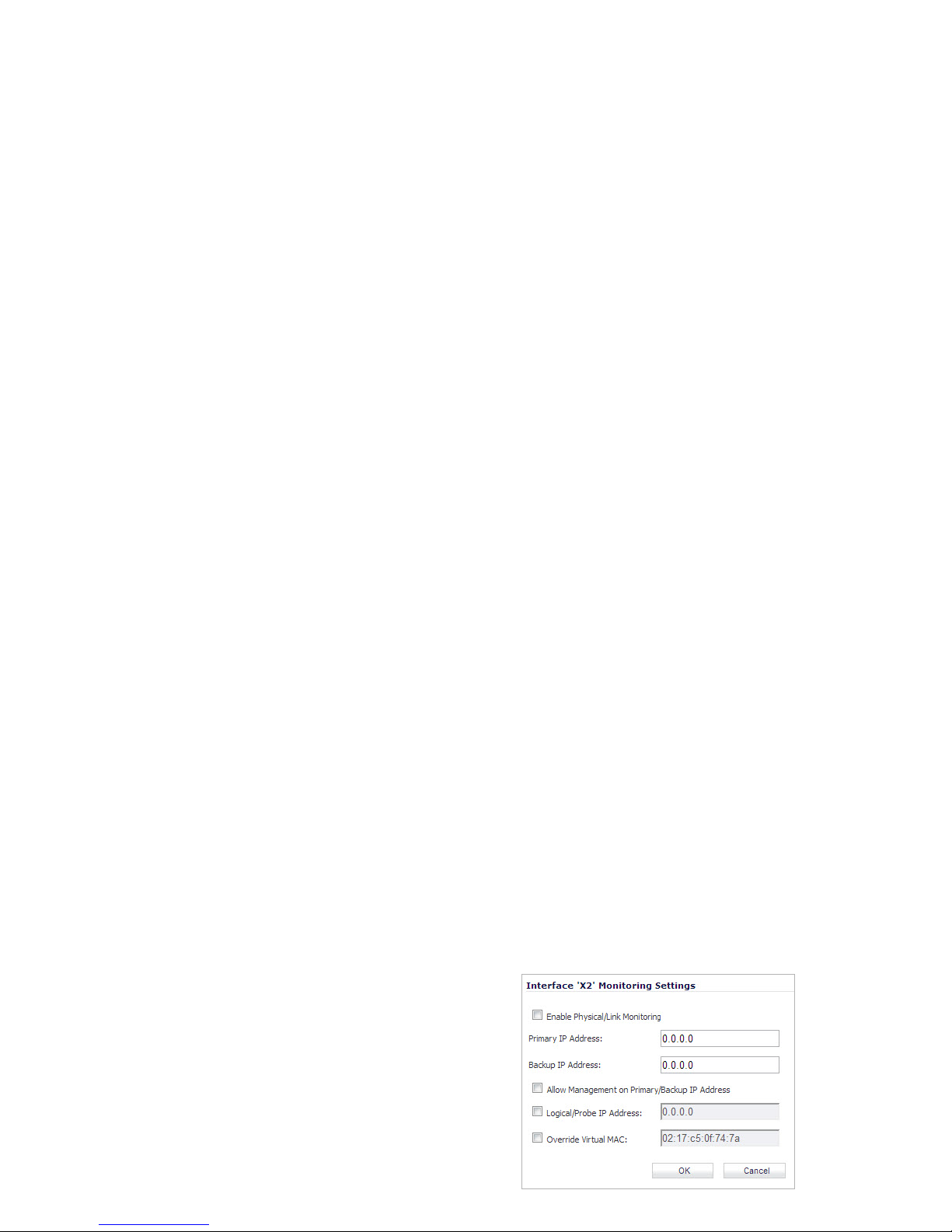
Navigate to the High Availability > Monitoring page to
configure the Monitoring settings.
1. Click the Configure icon of the Interface for which you
want to edit settings. The Edit HA Monitoring dialog box
displays.
Page 40

2. In the Primary IP Address field, enter the unique LAN or
WAN management IP address of the Primary appliance.
3. In the Secondary IP Address field, enter the unique LAN
or WAN management IP address of the Secondary
appliance.
4. Select the Allow Management on Primary/Secondary IP
Address checkbox.
5. Optionally Enable Physical / Link Monitoring by selecting
the checkbox.
6. Optionally enable Logical / Probe IP Address by selecting
the checkbox and providing the IP Address of the target
host.
7. Click OK.
You can repeat these steps to configure Monitoring on other
interfaces.
For more information regarding the optional settings, see the
SonicOS Administrator’s Guide.
Synchronize Settings
Once you have configured the HA setting on th e Pri m ar y De ll
SonicWALL security appliance, click the Synchronize Settings
button. You should see a HA Peer Firewall has been updated
message at the bottom of the management interface page. Also
note that the management interface displays Logged Into:
Primary SonicWALL Status: Active in the upper-right-hand
corner.
By default, the Include Certificate/Keys setting is enabled.
This specifies that Certificates, CRLs and associated settings
(such as CRL auto-import URLs and OCSP settings) are
synchronized between the primary and secondary units. When
Local Certificates are copied to the secondary unit, the
associated Private Keys are also copied. Because the
connection between the primary and secondary units is typically
protected, this is generally not a security concern.
Note: A compromise between the convenience of
synchronizing Certificates and the added security of not
synchronizing Certificates is to temporarily enable the
Include Certificate/Keys setting and manually
synchronize the settings, and then disable Include
Certificate/Keys.
To verify that primary and secondary Dell SonicWALL security
appliances are functioning correctly, wait a few minutes, then
power off the Primary Dell SonicWALL device. The secondary
Dell SonicWALL security appliance should quickly take over.
From your management workstation, test connectivity through
the secondary Dell SonicWALL by accessing a site on the
public Internet – note that the secondary Dell SonicWALL, when
active, assumes the complete identity of the primary, including
its IP addresses and Ethernet MAC addresses.
Page 41
Log into the secondary Dell SonicWALL’s unique LAN IP
address. The management interface should now display
Logged Into: Backup SonicWALL Status: Active in the
upper-right-hand corner.
Now, power the primary appliance back on, wait a few minutes,
then log back into the management inte rface. If stateful
synchronization is enabled (automatically disabling preempt
mode), the management GUI should still display Logged Into:
Backup SonicWALL St atus: Active in the upper-right-hand
corner.
If you are using the Monitor Interfaces feature, experiment with
disconnecting each monitored link to ensure correct
configuration.
HA License Configuration Overview
You can configure HA license synchronization by associating
two Dell SonicWALL security appliances as HA Primary and HF
secondary on MySonicWALL. Note that the secondary
appliance of your HA pair is referred to as the HF Secondary
unit on MySonicWALL. Also note that the secondary appliance
must be an identical model to the primary applicancy (such as
two NSA E5500 appliances).
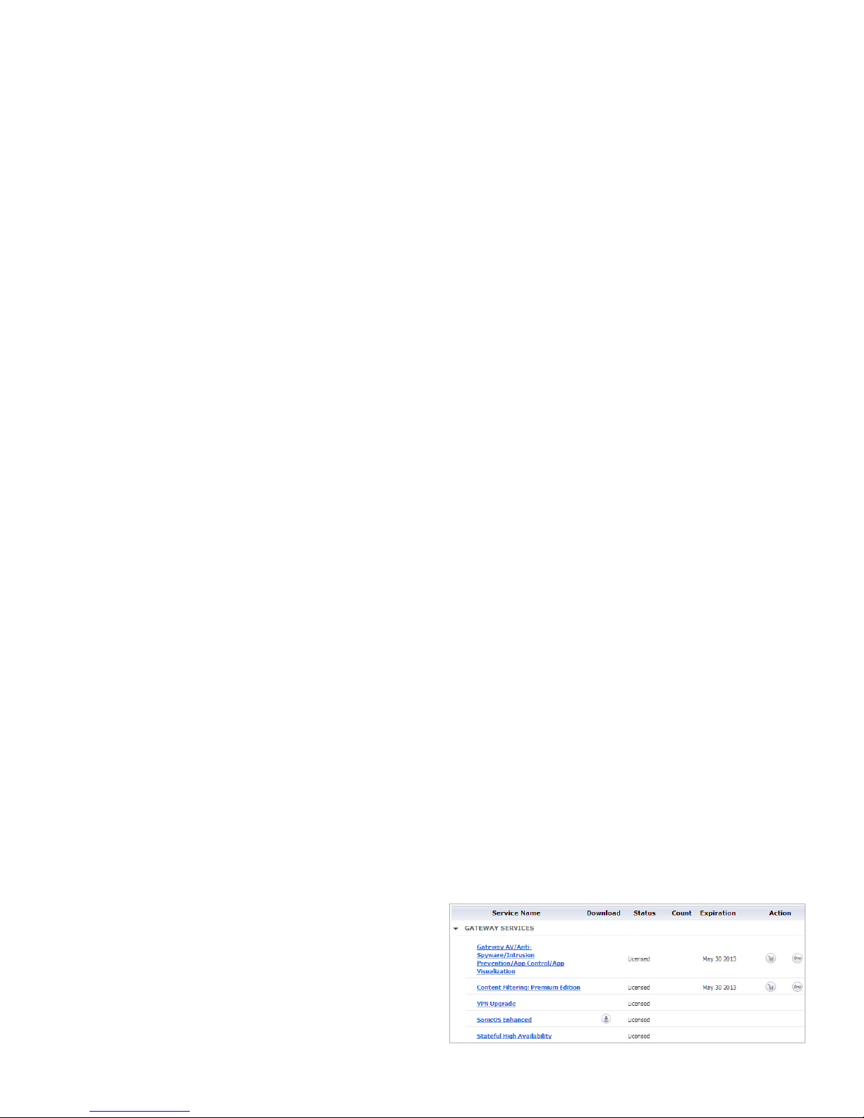
Y ou must purchase a single set of security services licenses for
the HA Primary appliance. To use Stateful HA, you must first
activate the Stateful High Availability Upgrade license for the
primary unit in SonicOS. This is automatic if the appliance is
connected to the Internet. See Registering and Licensing Your
Appliance on MySonicWALL, on page 20.
Page 42
License synchronization is used during HA so that the
secondary appliance can maintain the same level of network
protection provided before the failover. To enable HA, you can
use the SonicOS UI to configure your two appliances as a HA
pair in Active/Idle mode.
MySonicWALL provides several methods of associating the two
appliances. You can start by registering a new appliance, and
then choosing an already-registered unit to associate it with.
Y ou can associate two units that are both already registered. Or ,
you can select a registered unit and then add a new appliance
with which to associate it.
Note: After registering new Dell SonicWALL appliances on
MySonicWALL, you must also register each appliance
from the SonicOS management interface by logging
into the unique IP address assigned on the High
Availability > Monitoring page and then clicking the
registration link on the System > Status page. This
allows each unit to synchronize with the license server
and share licenses with the associated appliance.
Associating Pre-Registered Appliances
To associate two already-registered Dell SonicWALL security
appliances so that they can use HA license synchronization,
perform the following steps:
1. Login to MySonicWALL.
2. In the left navigation bar, click My Products.
3. On the My Products page, under Registered Products,
scroll down to find the appliance that you want to use as
the parent, or primary , unit. Click the product name or
serial number.
4. On the Service Management - Associated Products page,
scroll down to the Associated Products section.
5. Under Associated Products, click HF Secondary.
6. On the My Product - Associated Products page, in the text
boxes under Associate New Products, type the serial
number and the friendly name of the appliance that you
want to associate as the child/secondary unit.
7. Select the group from the Product Group drop-down list.
The product group setting specifies the mysonicwall users
who can upgrade or modify the appliance.
8. Click Register.
If You Are Following
Scenario...
Proceed to Section:
B - NAT with State Sync Pair Additional Deployment Configuration -
page 46
Page 43
Configuring L2 Bridge Mode
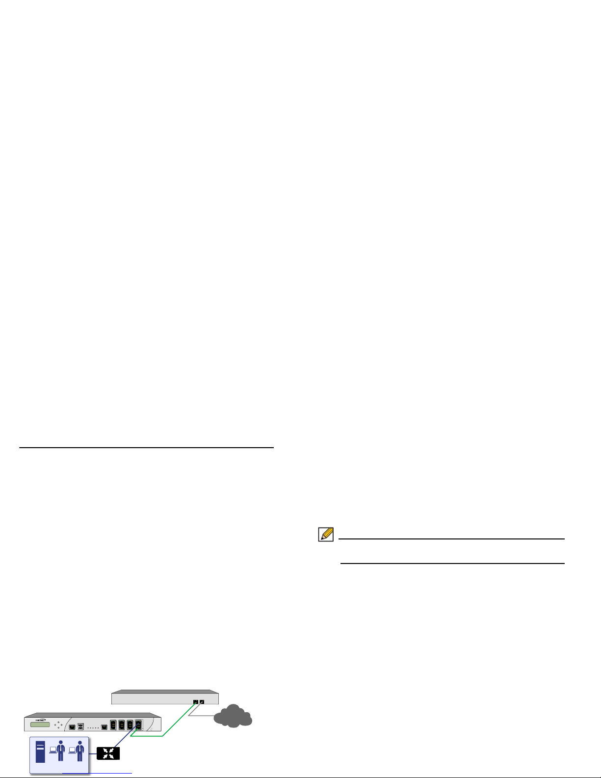
This section provides instructions to configure the Dell
SonicWALL NSA E8500 appliance in tandem with an existing
Internet gateway device. This section is relevant to users
following deployment scenario C.
This section contains the following sub-sections:
• Connection Overview - page 43
• Configuring the Primary Bridge Interface - page 43
• Configuring the Secondary Bridge Interface - page 44
Connection Overview
Connect the X1 port on your Dell SonicWALL NSA E8500 to the
LAN port on your existing Internet gateway device. Then
connect the X0 port on your NSA E8500 to your LAN resources.
Configuring the Primary Bridge Interface
The primary bridge interface is your existing Internet gateway
device. The only step involved in setting up your primary bridge
interface is to ens ure that the W AN interface is configured for a
static IP address. You will need this static IP address when
configuring the secondary bridge.
Note: The primary bridge interface must have a static IP
assignment.
E8500
Network Security Appliance
SonicWALL NSA E-Class
Network Gateway
L2 Bridge Link
Network Resources
X1
LAN
X0
Internet or
LAN Segment 2
Page 44
Configuring the Secondary Bridge Interface
Complete the following steps to configure the Dell SonicWALL
NSA E8500 appliance:
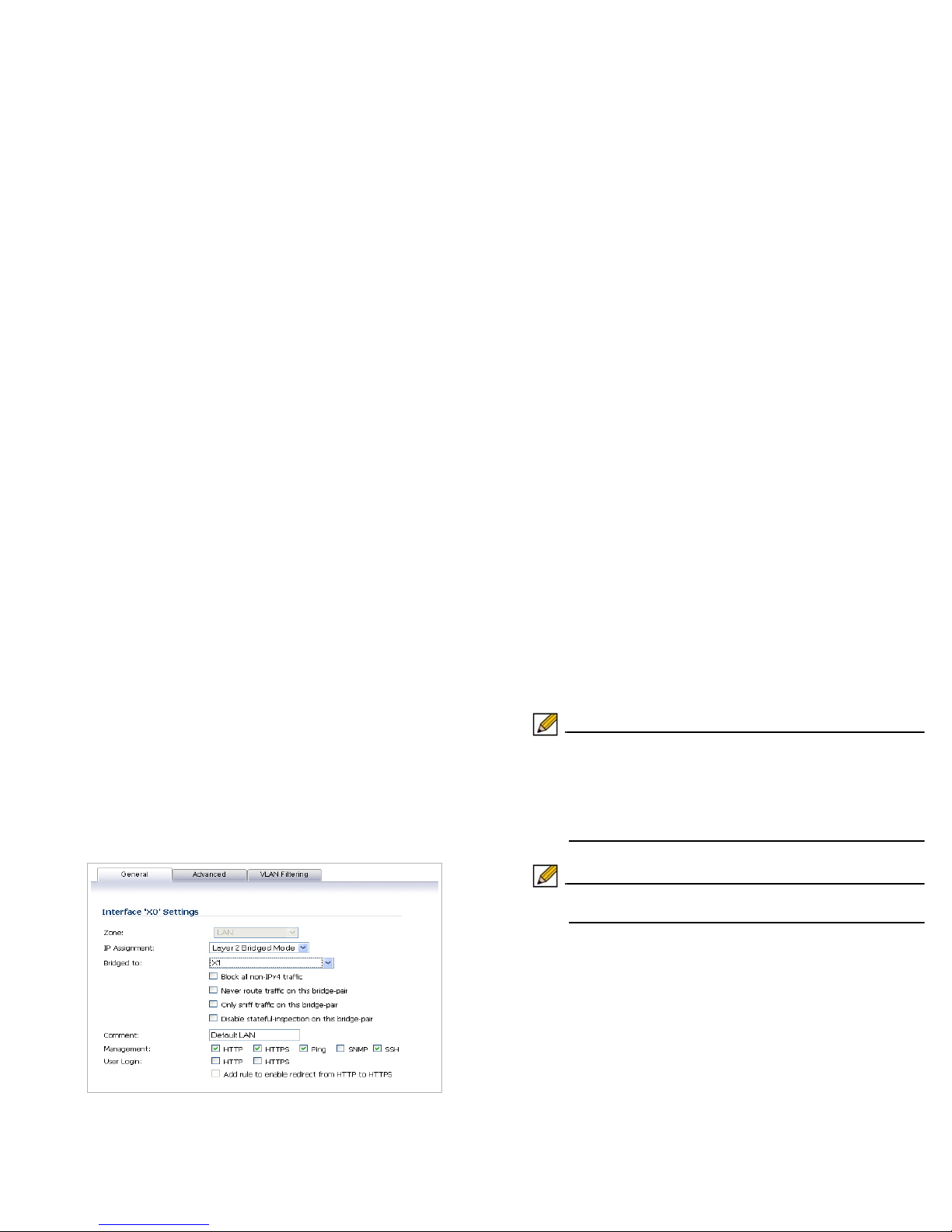
1. Navigate to the Network > Interfaces page from the
navigation panel.
2. Click the Configure icon in the right column of the X0 (LAN)
interface.
3. In the IP Assignment drop-down, select Layer 2 Bridged
Mode.
4. In the Bridged to drop-down, select the X1 interface.
5. Configure management options (HTTP, HTTPS, Ping,
SNMP, SSH, User logins, or HTTP redirects).
Note: Do not enable Never route traffic on the bridge-pair
unless your network topology requires that all packets
entering the L2 Bridge remain on the L2 Bridge
segments. You may optionally enable the Block all
non-IPv4 traffic setting to prevent the L2 bridge from
passing non-IPv4 traffic.
Note: Continue to the Additional Deployment Configuration
section, on page 46.
Page 45

Page 46

Additional Deployment Configuration
In this Section:
This section provides basic configuration information to begin building network security policies for your deployment. This section also
contains several SonicOS diagnostic tools and a deployment configuration reference checklist.
• An Introduction to Zones and Interfaces - page 47
• Creating a NAT Policy - page 48
• Enabling Security Services in SonicOS - page 51
• Applying Security Services to Zones - page 52
• Tro ubleshooting Diagnostic Tools - page 52
4
Page 47

An Introduction to Zones and Interfaces
Zones split a network infrast ructure into logi cal areas, each with
its own set of usage rules, security services, and policies. Most
networks include multiple definitions for zones, including those
for trusted, untrusted, public, encrypted, and wireless traffic.
Some basic (default) zone types include:
WAN—Untrusted resources outside your local network
LAN—Trusted local network resources
WLAN—Local wireless network resources originating from Dell
SonicWALL wireless enabled appliances such as SonicPoints.
DMZ—Local network assets that must be accessible from the
WAN zone (such as Web and FTP servers)
VPN—Trusted endpoints in an otherwise untrusted zone, such
as the WAN
The security features and settings configured for the zones are
enforced by binding a zone to one or more physical interfaces
(such as, X0, X1, or X2) on the Dell SonicWALL NSA E8500.
The X1 and X0 interfaces are preconfigured as WAN and LAN
respectively. The remaining ports can be configured to meet the
needs of your network, either by using basic zone types (WAN,
LAN, WLAN, DMZ, VPN) or configuring a custom zone type to
fit your network requirements (for example: Gaming Console
Zone, Wireless Printer Zone, Wireless Ticket Scanner Zone).
A Zone is a logical grouping of one or more interfaces designed
to make management, such as the definition and application of
access rules, a simpler and more intuitive process than
following a strict physical interface scheme.
By default, the Dell SonicWALL appliance’s stateful packet
inspection allows all communication from the LAN to the
Internet, and blocks all traffic from the Internet to the LAN. The
following behaviors are defined by the “Default” stateful
inspection packet access rule enabled in the Dell SonicWALL
appliance:
Originating Zone Destination Zone Action
LAN, WLAN WAN, DMZ Allow
DMZ WAN Allow
WAN DMZ Deny
WAN and DMZ LAN or WLAN Deny
Page 48

Creating a NAT Policy
The Network Address T ran sl a ti o n (NAT) engine in SonicOS
allows users to define granular NAT policies for their incoming
and outgoing traffic. By default, the Dell SonicWALL appliance
has a preconfigured NAT policy to allow all systems connected
to the LAN interface to perform Many-to-One NAT using the IP
address of the WAN interface, and a policy to not perform NAT
when traffic crosses between the other interfaces.
You can create multiple NAT policies on a Dell SonicWALL
appliance running SonicOS for the same object – for instance,
you can specify that an internal server use one IP address when
accessing Telnet servers, and to use a totally different IP
address for all other protocols. Because the NAT engine in
SonicOS supports inbound port forwarding, it is possible to hide
multiple internal servers off the WAN IP address of the Dell
SonicWALL appliance. The more granular the NAT Policy, the
more precedence it takes.
Before configuring NAT Policies, you must create all Address
Objects associated with the policy. For instance, if you are
creating a One-to-One NAT policy, first create Address Objects
for your public and private IP addresses.
Address Objects are one of four object classes (Address, User,
Service and Schedule) in SonicOS. These Address Objects
allow for entities to be defined one time, and to be re-used in
multiple referential instances throughout the SonicOS interface.
For example, take an internal Web server with an IP address of
67.115.118.80. Rather than repeatedly typing in the IP address
when constructing Access Rules or NAT Policies , Address
Objects allow you to create a single entity called “My Web
Server” as a Host Address Object with an IP address of
67.1 15.1 18.80. This Address Object, “My Web Server”, can then
be easily and efficiently selected from a drop-down menu in any
configuration screen that employs Address Objects as a
defining criterion.
Since there are multiple types of network address expressions,
there are currently the following Address Objects types:
• Host—Host Address Objects define a single host by its IP
address.
• Range—Range Address Objects define a range of
contiguous IP addresses.
• Network—Network Address Objects are like Range objects in
that they comprise multiple hosts, but rather than being bound
by specified upper and lower range delimiters, the boundaries
are defined by a valid netmask.
• MAC Address—MAC Address Objects allow for the
identification of a host by its hardware address or MAC (Media
Access Control) address.
• FQDN Address—FQDN Address Objects allow for the
identification of a host by its Fully Qualified Domain Names
(FQDN), such as www.sonicwall.com.
Page 49

SonicOS provides a number of Default Address Objects that
cannot be modified or deleted. Y ou can use the Default Address
Objects when creating a NAT policy, or you can create custom
Address Objects to use. All Address Objects are available in the
drop-down lists when creating a NAT policy.
Configuring Address Objects
The Network > Address Objects page allows you to create
and manage your Address Objects. You can view Address
Objects in the following ways using the View Style menu:
• All Address Objects—displays all configured Address
Objects.
• Custom Address Objects—displays Address Objects with
custom properties.
• Default Address Objects—displays Address Objects
configured by default on the Dell SonicWALL appliance.
To add an Address Object:
1. Navigate to the Network > Address Objects page.
2. Below the Address Objects table, click Add.
3. In the Add Address Object dialog box, enter a name for the
Address Object in the Name field.
4. Select the zone to assign to the Address Object from the
Zone Assignment drop-down list.
5. Select Host, Range, Network, MAC, or FQDN from the
Type menu.
• If you selected Host, enter the IP address in the IP
Address field.
• If you selected Range, enter the starting and ending IP
addresses in the Starting IP Address and Ending IP
Address fields.
• If you selected Network, enter the network IP address
and netmask in the Network and Netmask fields.
• If you selected MAC, enter the MAC address and
netmask in the Network and MAC Address field.
• If you selected FQDN, enter the domain name for the
individual site or range of sites (with a wildcard) in the
FQDN field.
6. Click OK.
Page 50

Configuring NAT Policies
NAT policies allow you to control Network Address Translation
based on matching combinations of Source IP address,
Destination IP address and Destination Services. Policy-based
NAT allows you to deploy dif ferent types of NAT simultaneously.
The following NAT configurations are available in SonicOS:
• Many-to-One NAT Policy
• Many-to-Many NAT Policy
• One-to-One NAT Policy for Outbound Traffic
• One-to-One NAT Policy for Inbound Traffic (Reflexive)
• One-to-Many NAT Load Balancing
• Inbound Port Address Translation via One-to-One NAT Policy
• Inbound Port Address Translation via WA N IP Address
This section describes how to configure a One-to-One NAT
policy. One-to-One is the most common NAT policy used to
route traffic to an internal server, such as a Web Server . Most of
the time, this means that incoming requests from external IPs
are translated from the IP address of the Dell SonicWALL
appliance WAN port to the IP address of the internal web
server.
For other NAT configurations, see the SonicOS Administrator’s
Guide.
An example configuration illustrates the use of the fields in the
Add NAT Policy procedure. To add a One-to-One NAT policy
that allows all Internet traffic to be routed through a public IP
address, two policies are needed: one for the outbound traffic,
and one for the inbound traffic. To add both parts of a One-toOne NAT policy, perform the following steps:
1. Navigate to the Network > NAT Policies page. Click Add.
The Add NAT Policy dialog box displays.
2. For Original Source, select Any.
3. For Translated Source, select Original.
4. For Original Destination, select X0 IP.
5. For Translated Destination, select Create new address
object and create a new address object using WAN for
Zone Assignment and Host for Type.
6. For Original Service, select HTTP.
7. For Translated Service, select Original.
8. For Inbound Interface, select X0.
9. For Outbound Interface, select Any.
10. For Comment, enter a short description.
11. Select the Enable NA T Policy checkbox.
12. Select the Create a reflexive policy checkbox if you want
a matching NAT Policy to be automatically created in the
opposite direction. This will create the outbound as well as
the inbound policies.
13. Click OK.
Page 51
Enabling Security Services in SonicOS
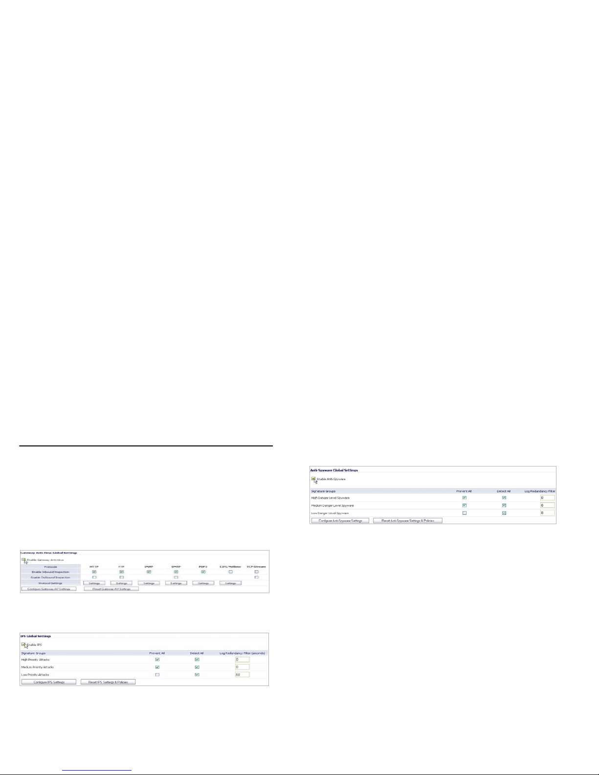
You must enabl e each security service individually in the
SonicOS user interface. See the following procedures to enable
and configure the following three basic security services:
Gateway Anti-Virus
Intrusion Prevention
Anti-Spyware
For more information on configuring your security services,
refer to the SonicOS Administrator’s Guide.
Page 52

Applying Security Services to Zones
A network zone is a logical group of one or more interfaces to
which you can apply security rules to regulate traffic passing
from one zone to another zone.
Security services such as Gateway Anti-Virus are automatically
applied to the LAN and WAN network zones when you activate
the license and enable the service. To protect other zones such
as the DMZ or Wireless LAN (WLAN), you must apply the
security services to the network zones. For example, you can
configure Dell SonicWALL Intrusion Prevention Service for
incoming and outgoing traffic on the WLAN zone to add more
security for internal network traffic.
To apply services to network zones:
1. Navigate to the Network > Zones page.
2. In the Zone Settings table, click the Configure icon for the
zone where you want to apply security services.
3. In the Edit Zone dialog box on the General tab, select the
checkboxes for the security services to enable on this
zone.
4. On the Edit Zone page, select the checkboxes for the
security services that you want to enable.
5. Click OK.
6. To enable security services on other zones, repeat steps 2
through 4 for each zone.
Troubleshooting Diagnostic Tools
SonicOS provides a number of diagnostic tools to help you
maintain your network and troubleshoot problems. Several tools
can be accessed on the System > Diagnostics page, and
others are available on other screens.
This section contains the following subsections:
• Using Ping - page 53
• Using the Active Connections Monitor - page 53
Page 53
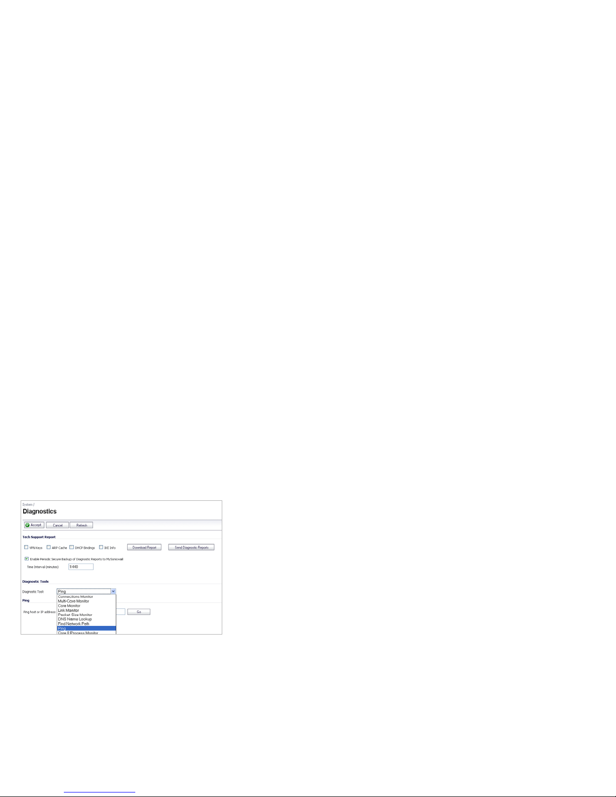
Using Ping
Ping is available on the System > Diagnostics page.
The Ping test bounces a packet off a machine on the Internet
and returns it to the sender. This test shows if the Dell
SonicWALL appliance is able to contact the remote host. If
users on the LAN are having problems accessing services on
the Internet, try pinging the DNS server, or another machine at
the ISP location. If the test is unsuccessful, try pinging devices
outside the ISP. If you can ping devices outside of the ISP, then
the problem lies with the ISP connection.
Using the Active Connections Monitor
The Active Connections Monitor displays real-time,
exportable (plain text or CSV), filterable views of all connections
to and through the Dell SonicWALL appliance. This tool is
available on the Systems > Diagnostics page.
You can filter the results to display only connections matching
certain criteria. You can filter by Source IP, Destination IP,
Destination Port, Protocol, Src Interface and Dst Interface.
Enter your filter criteria in the Active Connections Monitor
Settings table.
The fields you enter values into are combined into a search
string with a logical AND. Select the Group Filters box next to
any two or more criteria to combine them with a logical OR.
Page 54

Support and Training Options
In this Section
This section provides overviews of customer support and training options for the Dell SonicWALL NSA E8500.
• Customer Support - page 55
• Knowledge Portal - page 55
• User Forums - page 56
• Training - page 57
• Related Documentation - page 58
• Dynamic Tooltips - page 59
• Dell SonicWALL Live Product Demos - page 59
• Dell SonicWALL Secure Wireless Network Integrated Solutions Guide - page 60
5
Page 55
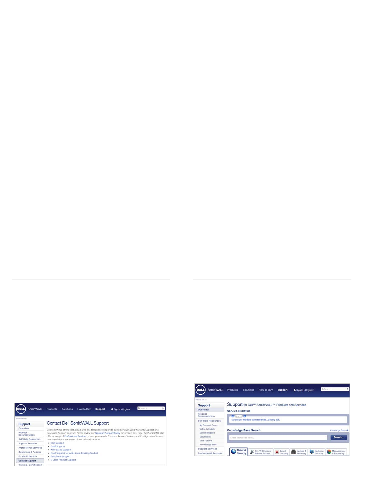
Customer Support
Designed for customers with Dell SonicWALL E-Class
solutions, Dell SonicWALL E-Class Support 24x7 delivers the
enterprise-class support features and quality of service that
enterprise companies require to keep their networks running
smoothly and efficiently. Dell SonicW ALL E-Class Support 24x7
is an around-the-clock support service that includes phone,
email and Web-based technical support, software and firmware
updates and upgrades and Advance Exchange hardware
replacement. Please Note: Continuous support is required on
all E-Class products.
For further information, visit:
http://www.sonicwall.com/us/support.html
Knowledge Portal
The Knowledge Portal is a resource which allows users to
search for Dell SonicWALL documents based on the following
types of search tools:
•Browse
• Search for keywords
• Full-text search
For further information, visit:
http://www.sonicwall.com/us/support/kb.asp
Page 56
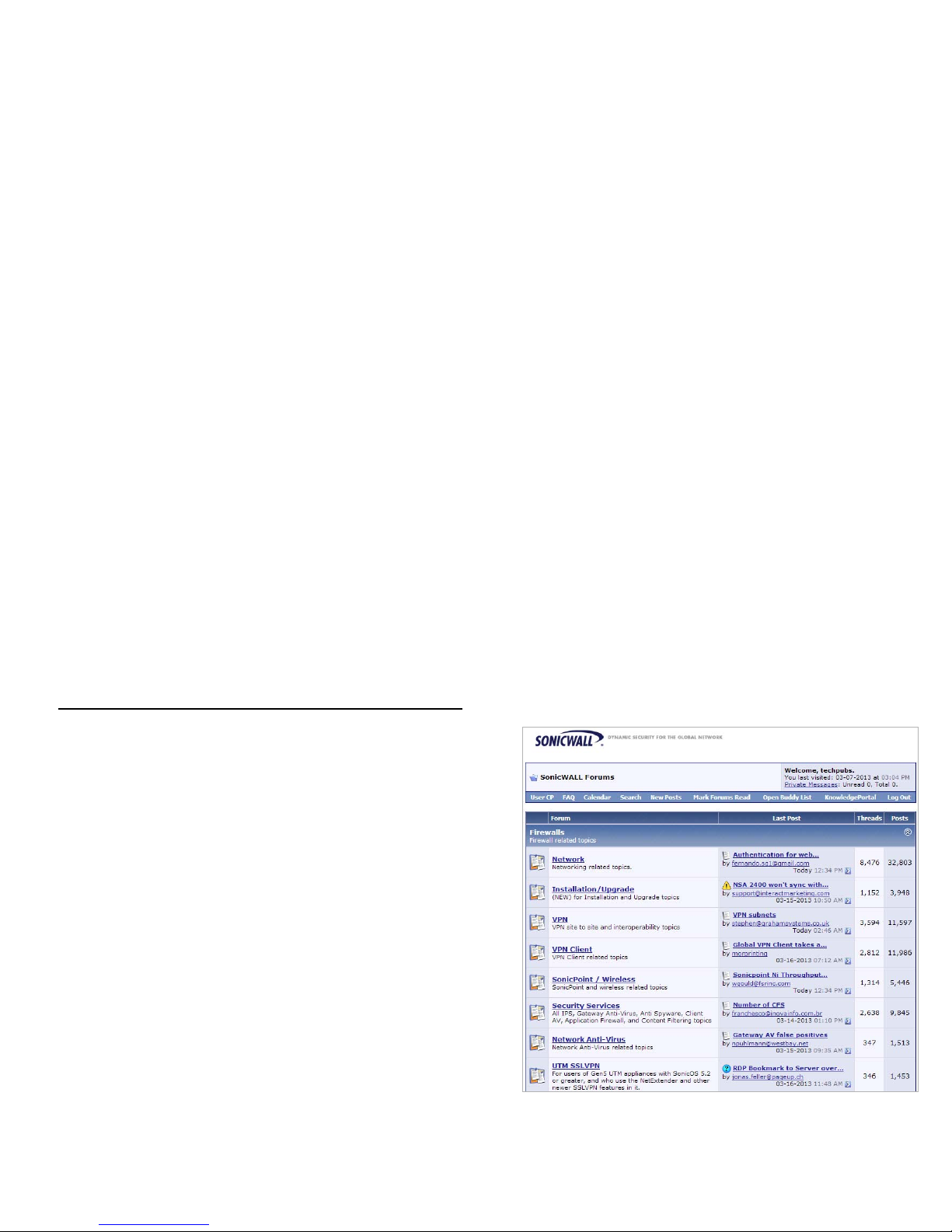
User Forums
The Dell SonicWALL User Forums is a resource that provides
users the ability to communicate and discuss a variety of
security and appliance subject matters. In this forum, the
following categories are available for users:
• Content Security Manager topics
• Continuous Data Protection topics
• Email Security related topics
• Firewall related topics
• Network Anti-Virus related topics
• Security Services and Content Filtering topics
• GMS and Analyzer related topics
• SonicPoint and Wireless related topics
• SSL VPN related topics
• Wireless WAN - 3G/4G related topi cs
• VPN Client related topics
• VPN site-to-site and interoperability topics
For further information, visit:
https://forum.sonicwall.com
Page 57
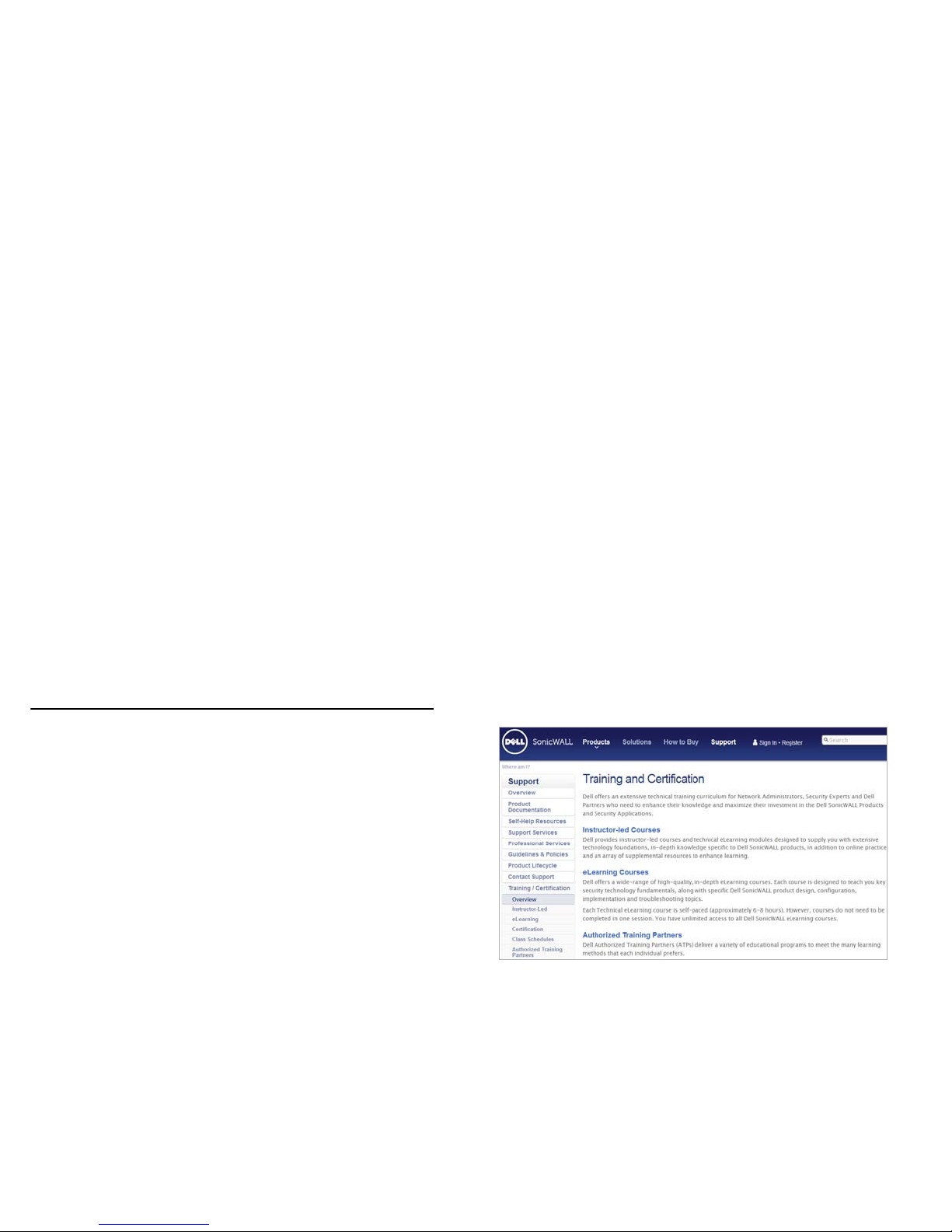
Training
Dell SonicWALL offers an extensive sales and technical training
curriculum for Network Administrators, Security Experts and
Dell SonicWALL Medallion Partners who need to enhance their
knowledge and maximize their investment in Dell SonicWALL
Products and Security Applications. Dell SonicWALL Training
provides the following resources for its customers:
• E-Training
• Instructor-Led Training
• Custom Training
• Technical Certification
• Authorized T raining Partners
For further information, visit:
http://training.sonicwall.com
Page 58
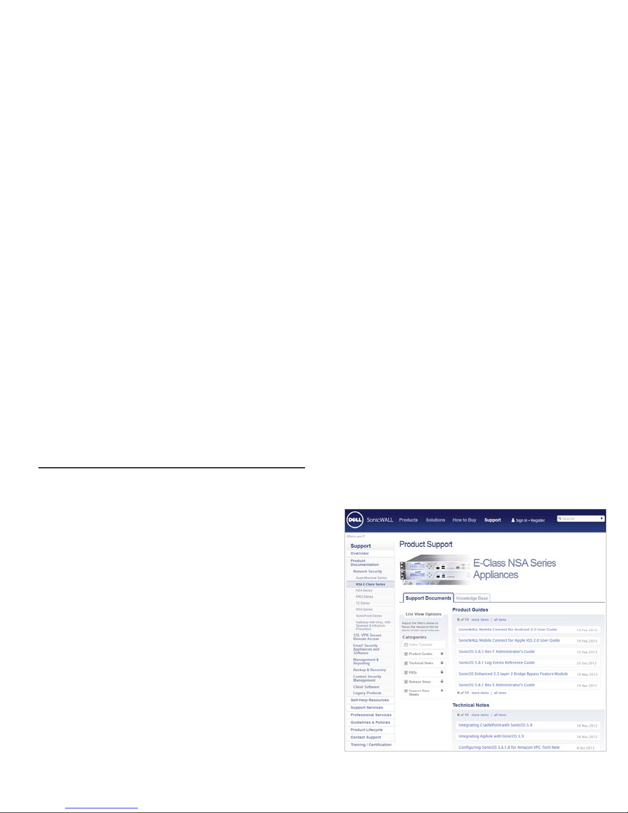
Related Documentation
See the following related documents for more information:
• SonicOS Administrator’s Guide
• SonicOS Release Notes
• SonicOS Feature Modules
• Application Firewall
• Dashboard
• HA License Sync
• Multiple Admin
• NAT Load Balancing
• Packet Capture
• RF Management
• Single Sign On
• SSL Control
• Virtual Access Points
• Dell SonicWALL GVC Administrator’s Guide
• Dell SonicWALL GMS Administrator’s Guide
• Dell SonicWALL GAV Administrator’s Guide
• Dell SonicWALL IPS Administrator’s Guide
• Dell SonicWALL Anti-Spyware Administrator’s Guide
• Dell SonicWALL CFS Administrator’s Guide
For further information, visit:
http://www.sonicwall.com/us/support.html
Page 59
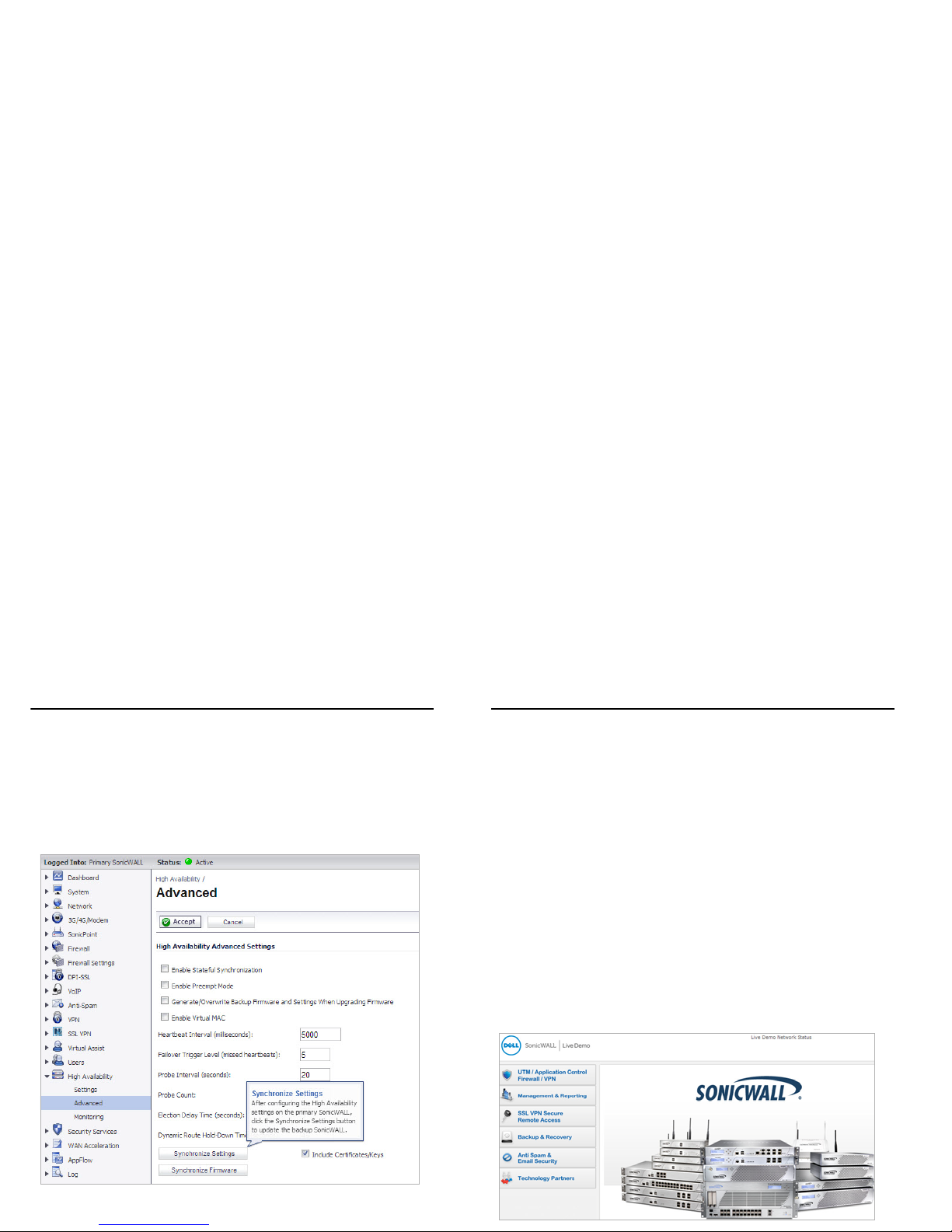
Dynamic Tooltips
SonicOS features dynamic tooltips that appear over various
elements of the GUI when the mouse hovers over them.
Elements that display these tooltips include text fields, radio
buttons, and checkboxes.
Dell SonicWALL Live Product Demos
The Dell SonicWALL Live Demo Site provides free test drives of
Dell SonicWALL security products and services through
interactive live product installations:
• Unified Threat Management Platform
• Secure Cellular Wireless
• Continuous Data Protection
• SSL VPN Secure Remote Access
• Content Filtering
• Secure Wireless Solutions
• Email Security
• GMS and Analyzer
For further information, visit: http://livedemo.sonicwall.com
Page 60
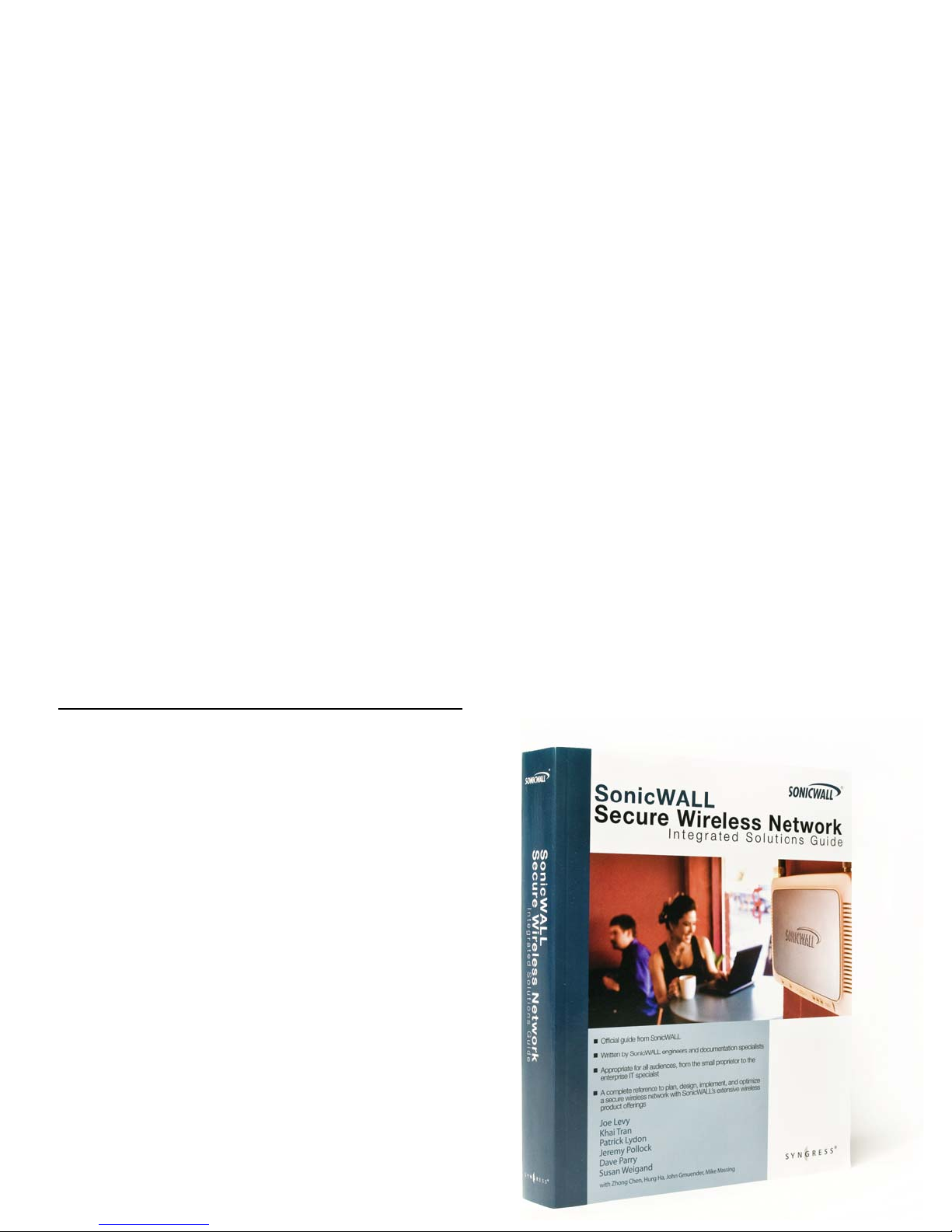
Dell SonicWALL Secure Wireless
Network Integrated Solutions Guide
Looking to go wireless? Have questions about what it takes to
build a truly “secure” wireless network? Check out the Dell
SonicWALL Secure Wireless Network Integrated Solutions
Guide. This book is the official guide to Dell SonicWALL’s
market-leading wireless networking and security devices.
This title is available in hardcopy at fine book retailers
everywhere, or by ordering directly from Elsevier Publishing at:
http://www.elsevier.com
Page 61

Page 62

Rack Mounting Instructions
In this Section:
This section provides illustrated rack mounting instructions for the Dell SonicWALL NSA E8500.
• Rack Mounting Instructions - page 63
Note: For more information on rack mounting requirements, see the Safety and Regulatory Information - page 69.
6
Page 63
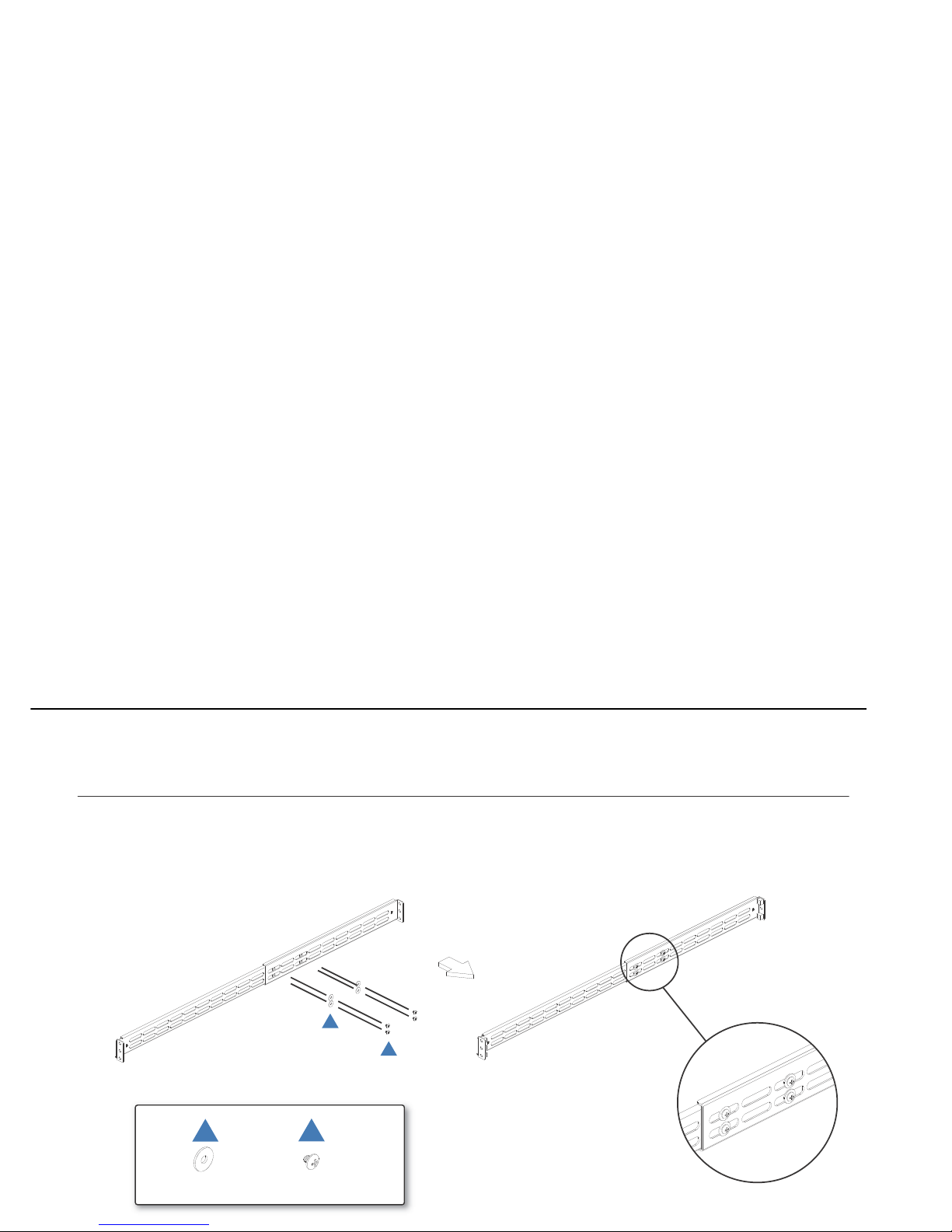
Rack Mounting Instructions
M4 SCREW*8WASHERS*8
Fasten 4 screws to the rail.
Assemble the Slide Rail
A
B
A
B
Page 64
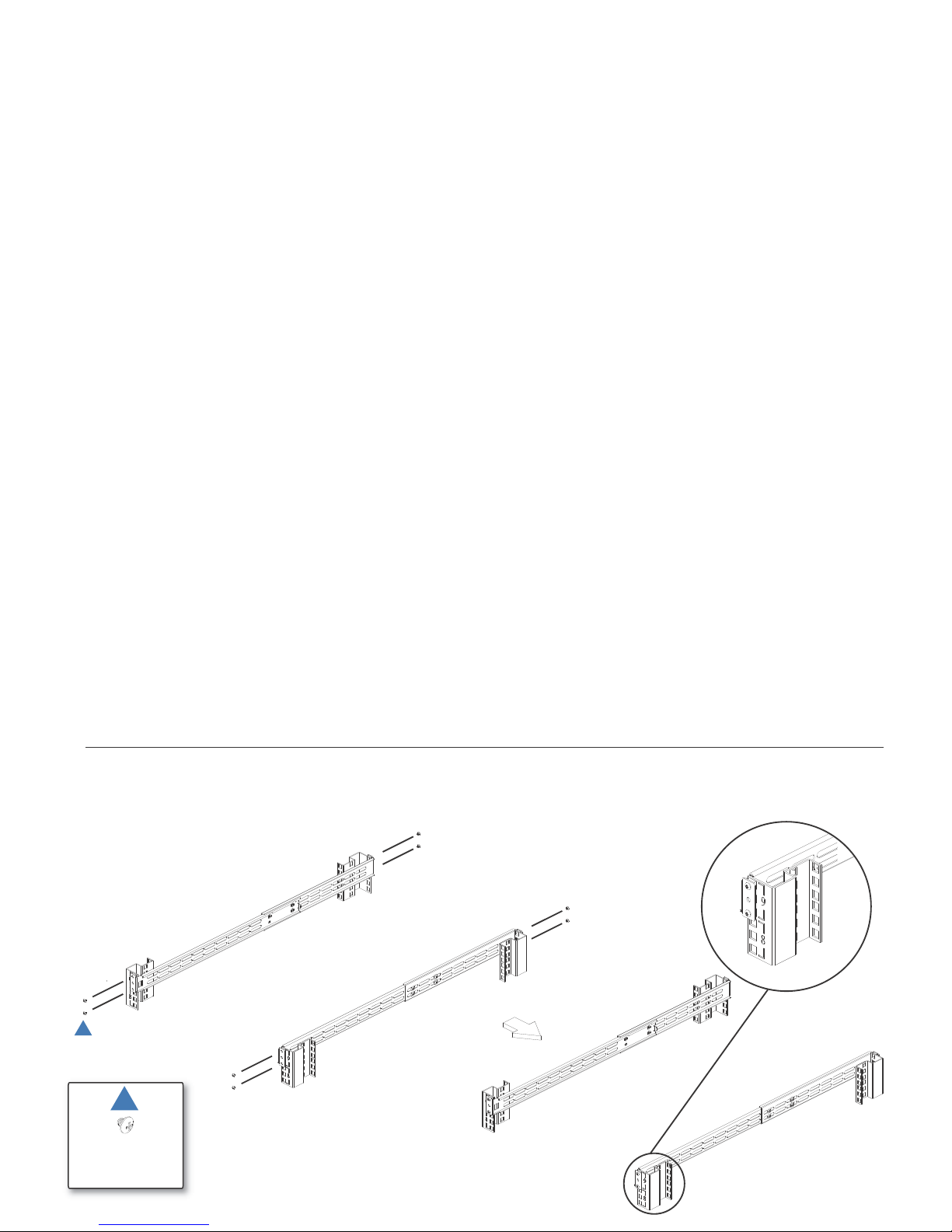
M5 SCREW*8
M5 Nut*8
Assemble the Slide Rail
Fasten two-sided screws to the rail.
C
C
Page 65
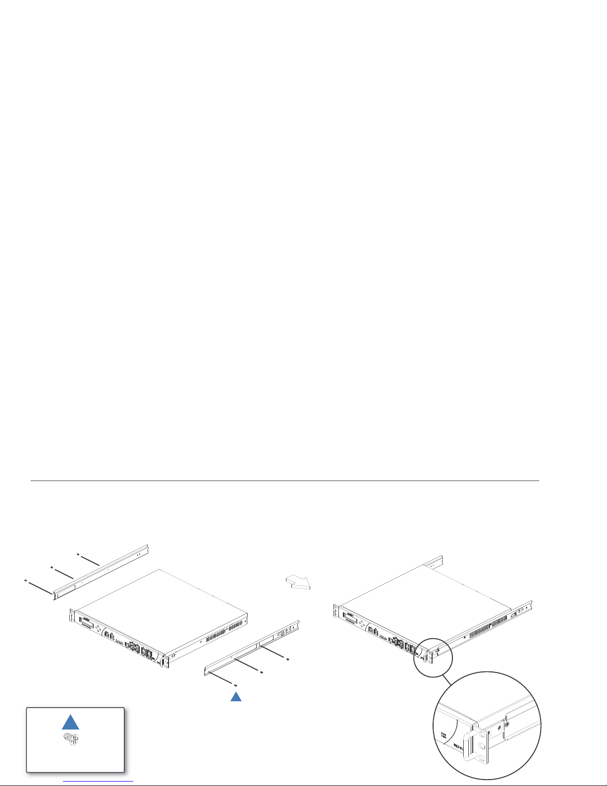
Assemble Inner Rail to Chassis
Fasten 6 screws to attach the inner channel onto the chassis.
M4 SCREW*6
D
D
Page 66
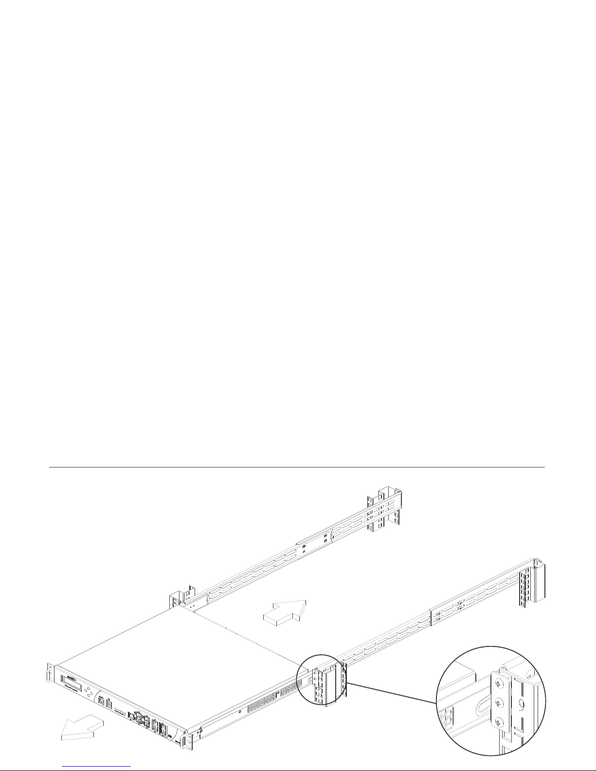
Insert Chassis to Frame
Push hook down to separate.
Slide inner channel into rails.
Page 67

Page 68

Product Safety and Regulatory Information
In this Section:
This section provides regulatory along with trademark and copyright information.
• Safety and Regulatory Information - page 69
• Warranty Information - page 73
• Copyright Notice - page 73
7
Page 69
Safety and Regulatory Information
Safety Instructions
The following conditions are required for proper installation:
• The Dell SonicWALL appliance is designed to be mounted in a st andard 19-inch
rack mount cabinet.
• Use the mounting hardware recommended by the rack manufacturer and ensure
that the rack is adequate for the application.
• Ensure that no water or excessive moisture can enter the unit.
• Allow unrestricted airflow around the unit and through the vents on the side of
the unit. A minimum of 1 inch (25.44mm) clearance is recommended.
• Route cables away from power lines, fluorescent lighting fixtures, and sources
of noise such as radios, transmitters, and broadband amplifiers.
• This product is not intended to be installed and used in a home or public area
accessible to the general population. When installed in schools, t his equipment
must be installed in a secure location accessible only by trained personnel.
• Mount in a location away from direct sunlight and sources of heat. A maximum
ambient temperature of 104º F (40º C) is recommended.
• If installed in a closed or multi-rack assembly, the operating ambient temperature
of the rack environment may be greater than the room ambient. Therefor e,
consideration should be given to installing the equipment in an environment
compatible with the maximum recommended ambient temperature.
• Mount the Dell SonicWALL appliances evenly in the rack in order to prevent a
hazardous condition caused by uneven mechanical loading.
• Four mounting screws, compatible with the rack design, must be used and hand tightened to ensure secure installation. Choose a mounting location where all
four mounting holes line up with those of the mounting bars of the 19-inch rack
mount cabinet.
• A suitably rated and approved branch circuit breaker shall be provided as part of
the building installation. Follow local code when purchasing materials or
components.
• Consideration must be given to the connection of the equipment to the supply
circuit. Appropriate consideration of equipment nameplate ratings must be used
when addressing this concern. Do not overload the circuit.
• Reliable grounding of rack-mounted equipment must be maintained. Particular
attention must be given to power supply connections other than direct
connections to the branch circuits, such as power strips.
• As shipped from the factory this Dell SonicWALL product includes two power
supplies for redundant AC power and added reliability. A field conversion is
available to convert to DC mains.
• To disconnect AC power, both power cords must be removed.
• The included power cord(s) are approved for use only in specific countries or
regions. Before using a power cord, verify that it is rated and appr oved for use in
your location.
• This model is shipped as AC mains configuration using standard 3 conductor
appliance couplers. A field conversion is available to change to DC mains. The
DC mains connector is a keyed square 6-pi n conductor with two blank l ocations.
• To disconnect DC power, an external properly-related disconnect device must
be provided by building or rack installation.
• Do not connect AC configured products to DC mains, and do not connect DC
configured products to AC. Detailed instructions are provided with the DC
conversion kit. Product must be configured as all DC or all AC.
• DC rating includes tolerances. Do not operate product outside of range shown
on product label.
• DC configuration includes input cable with protective earthing conductor (Green
and Yellow wire). This conductor is required to be connected to safety earth
ground of circuit.
• Never remove or install a power supply with the AC or DC power cord attached
to the power supply being removed or installed.
• Thumbscrews should be tightened with a tool after both installation and
subsequent access to the rear of the product.
• Before replacing the fan unit, carefully read and follow the instructions pr ovided
with the unit.
Regulatory Model/Type Product Name
1RK15-085 NSA E8500
Warning—Potential Hazard from Fan
Page 70

Lithium Battery Warning
The Lithium Battery used in the Dell SonicWALL I nternet security appli ance may
not be replaced by the user . The appliance must be returned t o a DellSo nicW ALL
authorized service center for replacement with the same or equivalent type
recommended by the manufacturer . If, for any reason, the battery or
Dell SonicWALL Internet security appliance must b e disposed of, do so followin g
the battery manufacture r's inst ruct ions.
Cable Connections
All Ethernet and RS232 (Console) cables are designed for intra-building
connection to other equipment. Do not connect these port s directly to
communication wiring or other wiring that exits the building where th e
Dell SonicWALL is located.
Sicherheitsanweisungen
Für eine ordnungsgemäße Montage sollten die folgenden Hinweise beachtet
werden:
• Das Dell SonicWALL Modell ist für eine Montage in einem standardmäßigen 19Zoll-Rack konzipiert.
• Vergewissern Sie sich, dass das Rack für dieses Gerät geeignet ist und
verwenden Sie das vom Rack-Hersteller empfohlene Montagezubehör.
• Stellen Sie sicher, dass das Gerät vor Wasser und hoher Luftfeuchtigkeit
geschützt ist.
• Stellen Sie sicher, dass die Luft um das Gerät herum zirkulieren kann und die
Lüftungsschlitze an der Seite des Gehäuses frei sind. Hier ist ein
Belüftungsabstand von mindestens 26 mm einzuhalten.
• Achten Sie darauf, das sich die Netzwerkkabel nicht in der unmittelbaren Nähe
von Stromleitungen, Leuchtstoffröhren und Störquellen wie Funksendern oder
Breitbandverstärkern befinden
• Dieses Produkt ist nicht dafür entwickelt, um in Bereichen mit öffentlichem
Zugang betrieben zu werden. Wenn es in Schulen betrieben wird, stellen Sie
sicher, dass das Gerät in einem abgeschlossenen Raum i nstalliert wir d, de r nur
von speziell ausgebildetem Personal betreten werden kann.
• Wählen Sie für die Montage einen Ort, der keinem direkten Sonnenlicht
ausgesetzt ist und sich nicht in der Nähe von Wärmequellen befindet. Die
Umgebungstemperatur darf nicht mehr als 40 °C betragen.
• Wenn das Gerät in einem geschlossenen 19"-Gehäuse oder mit mehreren
anderen Geräten eingesetzt ist, wird die Temperat ur in der Gehäuse höher sein
als die Umgebungstemperatur. Achten Sie darauf, daß die
Umgebungstemperatur nicht mehr als 40° C beträgt.
• Bringen Sie die Dell SonicWALL waagerecht im Rack an, um mögliche Gefahren
durch ungleiche mechanische Belastung zu vermeiden.
• Verwenden Sie für eine sichere Montage vier passende Befestigungsschrauben,
und ziehen Sie diese mit der Hand an. Wählen Sie einen Ort im 19-Zoll-Rack, wo
alle vier Befestigungen der Montageschien verwendet werden.
• Ein angemessen dimensionierter und geprüfte Sicherung, sollte Bestandt eil der
Haus-Installation sein. Bitte folgen die den lokalen Richt linien bei m Einkau f von
Material oder Komponenten.
• Prüfen Sie den Anschluss des Geräts an die Stromversorgung, damit der
Überstromschutz sowie die elektrische Leitung nicht von einer eventuellen
Überlastung der Stromversorgung beeinflusst werden. Prüfen Sie dabei
sorgfältig die Angaben auf dem Aufkleber des Geräts. Überlasten Si e nicht den
Stromkreis.
• Eine sichere Erdung der Geräte im Rack muss gewährleistet sein. Insbesondere
muss auf nicht direkte Anschlüsse an Stromquellen geachtet werden wie z. B.
bei Verwendung von Mehrfachsteckdosen.
• Dieses Produkt wird mit zwei Wechselstrom-Netzteilen zur redundanten
Stromversorgung fuer erhöhte Verfu¨gbarkeit ausgeliefert. Ein Umbaukit in
Gleichstromversorgung ist verfu¨gbar
• Um den Wechselstrom (AC) zu unterbrechen muessen beide Stromkabel
entfernt werden.
• Das im Lieferumfang enthaltene bzw. die im Lieferumfang enthaltenen
Netzkabel sind nur für die Verwendung in bestimmten Ländern und Regionen
zugelassen. Überprüfen Sie bitte vor der Verwendung eines Netzkabels, ob es
für die Verwendung in Ihrem Land oder Ihrer Region zugelassen ist und den
geforderten Normen entspricht.
• Die Wechselstrom Konfiguration verwendet standardisierte Kaltgerätekabel. Sie
können einem Umbaukit für Gleichstrom bestellen. Der Gleichstromanschluss ist
ein quadratischer 6-adriger Anschluss mit zwei blinden Punkten.
• Um den Gleichstrom (DC) zu unterbrechen, muss ein externes,
ordnungsgemaess bewertetes Unterbrechungsgeraet durch die Stromzufuhr im
Gebaeude oder das Rack zur Verfuegung gestellt werden.
• Schließen Sie kein Wechselstrom konfiguriertes Produkt an Gleichst rom an. Und
schließen Sie kein Gleichstrom konfiguriertes Produ kt an Wechselstrom an. Das
Umbaukit beinhaltet eine detaillierte Beschreibung. Das Gerät muss komplett mit
Gleichstrom oder Wechselstrom konfiguriert sein.
• Gleichstrom akzeptiert Toleranzen. Betreiben Sie das Gerät nicht außerhalb des
Bereiches, der auf dem Aufkleber des Gerätes angegeben ist.
• Die Gleichstrom Konfiguration beinhaltet einen Anschlusskabel mit Erdung
(Grün-Gelbes Kabel). Diese Kabel muss an den Erdungsschaltkreis
angeschlossen werden.
• Wenn Sie das Netzteil wechseln, entfernen Sie unbedingt die Stromversorgung
von dem zu wechselnden Netzteil.
• Vergewissern Sie sich, dass die Schrauben nach dem Austausch mit
entsprechendem Werkzeug fest angezogen werden.
Page 71
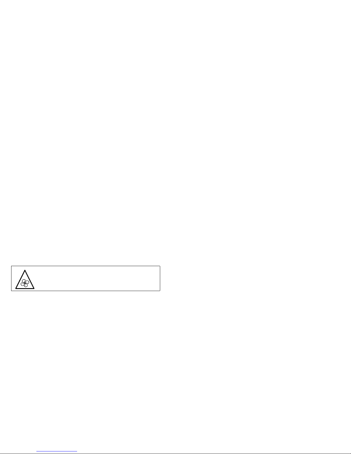
• Lesen Sie vor dem Austausch der Lüftereinheit die Anleitung, d ie mit dem Gerät
geliefert wurde und befolgen Sie die Anweisungen.
Hinweis zur Lithiumbatterie
Die in der Internet Security Appliance von Dell SonicWALL verwendete
Lithiumbatterie darf nicht vom Benutzer ausgetauscht werden. Zum Au stauschen
der Batterie muss die Dell SonicWALL in ein von DellSo nicW ALL autorisiertes
Service-Center gebracht werden. Dort wird die Batterie durch denselbe n oder
entsprechenden, vom Hersteller empfohlenen Batt erietyp ersetzt. Bea chten Sie
bei einer Entsorgung der Batterie oder der DellSonicWALL Internet Security
Appliance die diesbezüglichen Anweisungen des Herstellers.
Kabelverbindungen
Alle Ethernet- und RS232-C-Kabel eignen sich für die Verbindung von Geräten in
Innenräumen. Schließen Sie an die Anschlüsse der Dell SonicWALL keine Kabel
an, die aus dem Gebäude in dem sich das Gerät befindet herausgeführ t werden.
安全說明
需要滿足以下條件以進行正確安裝:
•戴爾 SonicWALL 設備被設計成安裝在一個標準的 19 吋機架安
裝櫃。需要滿足以下條件以進行正確安裝:
•使用機架製造商推薦的裝載硬體,確認機架足夠裝置所需
•請確認裝置內不會滲入水分或過多的濕氣。
•裝置週邊請保持通風,特別是裝置通風口側。建議裝置與牆
壁間至少要有 1 英吋 (25.44 公釐 ) 的淨空。
•纜線的路徑應遠離電源線、日光燈,以及會產生雜訊的來源,
如無線電、發送器與寬頻放大器。
•本產品的設計目的不是安裝並使用於住家或一般大眾可接觸
到的公共區域。如果是安裝在學校,本設備只能安裝在受訓人
員能接觸到的安全位置。
•架設位置需遠離陽光直射與熱源。建議周圍溫度最高溫不 要
超過 104°F (40°C)。
•如果是安裝於封閉式或多組機架配件,機架環境的周圍操作
溫度可能會高過室內周遭。因此,在與上述建議之最高周圍溫
度相容的環境中安裝設備時,應將此列入考量。
•將 戴爾 SonicWALL 裝置平坦地裝設在機架中,如此才能避免
因不均勻的機械負荷造成危險狀況。
•必須使用四顆與機架設計相容的安裝螺釘,並用手鎖緊螺釘,
確定安裝牢固。選擇一個安裝位置,將四個裝載洞孔對齊 19
吋架設機櫃的安裝桿。
•應當提供一個合適額定值並且已被認可的分支電路斷路器作
為安裝該裝置的一部分。在購買材料或部件時,應遵循當地安
全代碼。
•必須留心裝置與電源電路的連接問題,電路過載對過電流保
護與電路電線的影響需降至最低。解決這個問題時,需正確考
慮裝置銘牌額定值。不要過載電路。
•必須維護可靠的機架裝載設備接地。必須特別留意電源供應
器連線,而不是直接連接到電源板之類的分支電路。
•從工廠運出時,這個戴爾 SonicWALL 產品包括為後備交流電
源和增加可靠性而附帶的兩個電源。 可用提供的地區電流轉換
器轉換成直流電源。
•要斷開交流電源,兩條電源線都必須被拔除。
•隨附的電源線僅限於特定的國家或地區使用。使用前,請確
認電源線的額定值且已被認可在你的地區上使用。
Achtung—Lüfter Potentielle Gefahrenquelle
Page 72
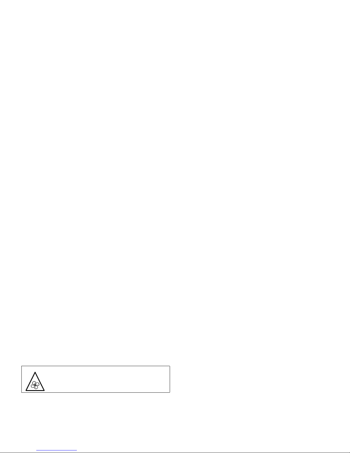
•這個型號出貨時附帶的交流電源,是標準三芯器具耦合器的配
置。可用提供的地區電流轉換器轉換成直流電源。 直流 (DC)
電源連接器為具有特定方向連接的方形連接器,帶六芯接頭以
及兩個空白位置。
•要斷開直流電源,必須有一個由建築物本身或機架安裝所提供
的外部適當的額定斷路裝置。
•不要把交流配置的產品連接到直流電源,也不要把直流配置的
產品連接到交流電源。在直流轉換器套件中有詳細說明。產品
必須設定為全直流或全交流。
•直流讀數包括公差。不要在產品標籤標示的範圍以外操作產
品。
•直流配置包括帶有保護接地導體的輸入電纜 (綠色和黃色電
線)。此導體必須連接到安全接地電路。
•切勿在交流電源線還連接著電源時移除或安裝電源。
•當安裝及後續接觸產品背面之後,必須用工具將指旋螺釘鎖
緊。
•更換風扇部件前,請仔細閱讀,並遵循所提供的指示。
鋰電池警告
使用者不得自行更換 戴爾 SonicWALL 網際網路安全性裝置中使
用的鋰電池。必須將 戴爾 SonicWALL 送回
戴爾 SonicWALL 授權
的服務中心,以更換相同的鋰電池或製造商推薦的同類型鋰電
池。若因任何原因必須丟棄電池或
戴爾 SonicWALL 網際網路安
全性裝置,請嚴格遵守電池製造商的指示。
纜線連結
所有乙太網路與 RS232 ( 主控台 ) 線路都是為與其他裝置進行內
建連接所設計的。請不要將這些連接埠直接連接至通訊線路,或
其他連出 戴爾 SonicWALL 所在建築的線路。
FCC Part 15 Class A Notice
NOTE: This equipment was tested and found to comply with the limits for a Class A
digital device, pursuant to Part 15 of the FCC Rules. These limits are d esigned to
provide reasonable protection against harmful interference when the equipment is
operated in a commercial environment. This equipment generates, uses, and can
radiate radio frequency energy . And if not inst alled and used in accordance with the
instruction manual, the device may cause harmful interference to radio
communications. Operation of this equipment i n a residential area is likely to cause
harmful interference in which case the user is requir ed to correct the interfere nce at
his own expense.
Caution: Modifying this equipment or using th is equipment for purposes not shown
in this manual without the written consent of Dell, Inc. could void the user’s
authority to operate this equipment.
BMSI Statement
警告使用者:
此為甲類資訊技術設備,於居住環境中使用時,可能會造成射
頻擾動,在此種情況下,使用者會被要求採取某些適當的對策。
VCCI Statement
この装置は、クラスA情報技術装置です。この装置を家庭環境
で使用すると電波妨害を引き起こすことがあります。この場合
には使用者が適切な対策を講ずるよう要求
されることがあります。 VCCI - A
風扇潛在危險警告
Page 73
Canadian Radio Frequency Emissions Statement
This Class A digital apparatus complies with Canadian ICES- 003.
Cet appareil numérique de la classe A est conforme à toutes la norme NMB-003
du Canada.
Complies with EN 55022 Class A and CISPR22
Class A
Warning: This is a class A product. In a domestic environ ment, this product may
cause radio interference in which case the user may be required to take adequate
measures.
Declaration of Conformity
Application of council Directive 2004/108/EC (EMC) and
2006/95/EC (L VD)
Standards to which conformity is declared
EN 55022 (2006) +A1 (2007) Class A
EN 55024 (1998) +A1 (2001), +A2 (2003)
EN 61000-3-2 (2006)
EN 61000-3-3 (2008)
EN 60950-1 (2006) +A1 1
National Deviations: AR, AT, AU, BE, BR, CA, CH, CN, CZ,
DE, DK, FI, FR, GB, GR, HU, IL, IN, IT, JP, KE,
KR, MY , NL, NO, PL, SE, SG , SI, SK, US
Regulatory Information for Korea
All products with country code “A” and “J” are made in the USA.
All products with country code “B” are made in China.
All products with country code "C" or "D" are made in Taiwan R.O.C.
All certificates held by Secuwide, Corps.
Warranty Information
All Dell SonicWALL appliance s come with a 1-year Limited Har dware W arranty
which provides delivery of critical replacement parts for defective p arts und er
warranty. V isit the Warranty Information page details on your product’s warranty:
http://www.sonicwall.com/us/en/support/Services.html#tab=warranty
Copyright Notice
© 2013 Dell, Inc.
All rights reserved.
Under the copyright laws, this manual or the software descri bed within, cannot be
copied, in whole or part, without the writt en consent of the manufa cturer, except in
the normal use of the software to make a backup copy. The same proprietary and
copyright notices must be affixed to any permitted copies as were af fixed to the
original. This exception does not allow copies to be made for others, whether or not
sold, but all of the material purchased (with all backup copies) can be sold, given,
or loaned to another person. Under the law , copyin g includes transla ting into
another language or format.
Specifications and descriptions subject to cha nge without notice.
Ministry of Information and Telecommunication
Certification Number SWL-1RK15-055
Page 74

 Loading...