

Page 1

Dell Networking
S6000 System
Getting Started Guide
Publication Date: October 2013
Regulatory Model: S6000
Page 2
Notes, Cautions, and Warnings
NOTE: A NOTE indicates important information that helps you make better use
of your computer.
CAUTION: A CAUTION indicates potential damage to the hardware or loss
of data if you do not follow the instructions.
WARNING: A WARNING indicates a potential for property damage,
personal injury, or death.
If you purchased a Dell n Series computer, any references in this publication to
Microsoft Windows operating systems are not applicable.
____________________
Information in this publication is subject to change without notice.
© 2013 Dell Inc. All rights reserved.
Reproduction of these materials in any manner whatsoever without the written permission of Dell Inc.
is strictly forbidden.
Trademarks used in this text: Dell™, the DELL logo, Dell Precision™, OptiPlex™, Latitude™,
PowerEdge™, PowerVault™, PowerConnect™, OpenManage™, EqualLogic™, KACE™,
FlexAddress™ and Vostro™ are trademarks of Dell Inc. Intel®, Pentium®, Xeon®, Core™ and
Celeron® are registered trademarks of Intel Corporation in the U.S. and other countries. AMD® is a
registered trademark and AMD Opteron™, AMD Phenom™, and AMD Sempron™ are trademarks
of Advanced Micro Devices, Inc. Microsoft®, Windows®, Windows Server®, MS-DOS® and
Windows V ista® are either trademarks or registered trademarks of Microsoft Corporation in the United
States and/or other countries. Red Hat Enterprise Linux® and Enterprise Linux® are registered
trademarks of Red Hat, Inc. in the United States and/or other countries. Novell® is a registered
trademark and SUSE ™ is a trademark of Novell Inc. in the United States and other countries. Oracle®
is a registered trademark of Oracle Corporation and/or its affiliates. Citrix®, Xen®, XenServer® and
XenMotion® are either registered trademarks or trademarks of Citrix Systems, Inc. in the United States
and/or other countries. VMware®, Virtual SMP®, vMotion®, vCenter®, and vSphere® are registered
trademarks or trademarks of VMWare, Inc. in the United States or other countries.
Other trademarks and trade names may be used in this publication to refer to either the entities claiming
the marks and names or their products. Dell Inc. disclaims any proprietary interest in trademarks and
trade names other than its own.
Regulatory Model: S6000
2013 - 10 P/N YDY1V Rev. A00
Page 3

Contents
Contents 1
1 About this Guide . . . . . . . . . . . . . . . . . . . . . . . . . . 1
2 Introduction . . . . . . . . . . . . . . . . . . . . . . . . . . . . . 3
Product Description . . . . . . . . . . . . . . . . . . . . . . . . . . . 3
3 Hardware Overview . . . . . . . . . . . . . . . . . . . . . . . 5
I/O Panel . . . . . . . . . . . . . . . . . . . . . . . . . . . . . . . . . 6
Utility Panel
. . . . . . . . . . . . . . . . . . . . . . . . . . . . . . . 7
Power Supplies
. . . . . . . . . . . . . . . . . . . . . . . . . . 7
Fans
. . . . . . . . . . . . . . . . . . . . . . . . . . . . . . . . 8
System Status
. . . . . . . . . . . . . . . . . . . . . . . . . . . . . . 9
4 Installation. . . . . . . . . . . . . . . . . . . . . . . . . . . . . 13
Unpacking the Switch . . . . . . . . . . . . . . . . . . . . . . . . 13
Package Contents
. . . . . . . . . . . . . . . . . . . . . . . . 13
Unpacking Steps
. . . . . . . . . . . . . . . . . . . . . . . . . 13
Installing an AC or DC Power Supply
. . . . . . . . . . . . . . . . . 14
Rack Mount the Switch
. . . . . . . . . . . . . . . . . . . . . . . . 15
Rack Mounting Safety Considerations
. . . . . . . . . . . . . . 15
Installing the Dell ReadyRails System
. . . . . . . . . . . . . . 16
Installing the Switch
. . . . . . . . . . . . . . . . . . . . . . . 20
5 Technical Specifications . . . . . . . . . . . . . . . . . . . 23
Chassis Physical Design . . . . . . . . . . . . . . . . . . . . . . . 23
Environmental Parameters
. . . . . . . . . . . . . . . . . . . . . . 23
Power Requirements
. . . . . . . . . . . . . . . . . . . . . . . . . 24
Page 4

Contents
2 Contents
6 Installing the Software . . . . . . . . . . . . . . . . . . . . 25
Navigating CLI Modes . . . . . . . . . . . . . . . . . . . . . . . . . 25
Console Access
. . . . . . . . . . . . . . . . . . . . . . . . . . . . 25
Default Configuration
. . . . . . . . . . . . . . . . . . . . . . . . . 27
Configuring Layer 2 (Data Link) Mode
. . . . . . . . . . . . . . . . 27
Configuring a Host Name
. . . . . . . . . . . . . . . . . . . . . . . 27
Accessing the System Remotely
. . . . . . . . . . . . . . . . . . . 28
Configuring the Management Port IP Address
. . . . . . . . . 28
Configuring the Management Route
. . . . . . . . . . . . . . . 29
Configuring the Username and Password
. . . . . . . . . . . . 29
Configuring the Enable Password
. . . . . . . . . . . . . . . . . . . 29
Creating a Port-based VLAN
. . . . . . . . . . . . . . . . . . . . . 30
Assigning Interfaces to a VLAN
. . . . . . . . . . . . . . . . . 30
Assigning an IP Address to a VLAN
. . . . . . . . . . . . . . . 32
Connecting the S6000 to the Network
. . . . . . . . . . . . . . . . . 32
Page 5

About this Guide 1
1
About this Guide
This document is intended as a Getting Started Guide to get new systems up and
running and ready for configuration. For complete installation and configuration
information, refer to the documents listed in
Table 1-1
.
Table 1-1. S6000 Documents
Information Documentation
Hardware installation and power-up
instructions
Installing the S6000 System
Software configuration FTOS Configuration Guide for the S6000
System
Command line interface FTOS Command Line Reference Guide for
the S6000 System
Latest updates FTOS Release Notes for the S6000 System
Page 6

2 About this Guide
Page 7

Introduction 3
2
Introduction
This document provides basic information about the S6000 switch, including
how to install the switch and perform the initial configuration. For information
about how to configure and monitor switch features,
refer to
the FTOS
Configuration Guide for the S6000 System, which is available on the Dell
Support website at support.dell.com/support.
This document contains the following sections:
• Hardware Overview
• Installation
• Technical Specifications
• Installing the Software
Product Description
The S6000 is a fully featured switch/router one rack unit (RU) system that you
can deploy as a spine, leaf, or top of rack (ToR) device where you require 10Gb
and/or 40Gb connections. It contains 32 ports of 40G that you can use to create a
configuration of 96 ports of 10G small form-factor pluggable plus (SFP+) (using
breakout cables) and eight ports of 40G quad small form-factor pluggable
(QSFP).
The S6000 switch runs the Dell Networking operating system (FTOS),
providing switching, bridging, and routing functionality for transmitting data,
storage, and server traffic.
In a data center network, the S6000 switch provides converged network support
and interoperates with Dell Networking and third-party network devices. The
switch supports
data center bridging (DCB) features and optimizes
connectivity
between servers and storage devices using Fibre Channel over Ethernet (FCoE)
and internet small computer system interface (iSCSI) links.
Page 8

4 Introduction
By providing increased 40GbE bandwidth for device interconnection in a shared
network storage environment, with the possibility of splitting 40GbE quad small
form-factor pluggable plus (QSFP+) uplinks into 10GbE SFP+ connections, the
S6000 switch is perfectly positioned to help transition a data center with
multiple speed requirements.
Page 9

Hardware Overview 5
3
Hardware Overview
This section contains information about device characteristics and modular
hardware configurations for the S6000 switch.
The S6000 has the following physical dimensions:
• 434 x 460 x 43.5 mm (W x D x H).
• 17.09 x 18.11 x 1.71 inches (W x D x H).
The S6000 has a chassis design with 1280Gbps switching bandwidth as listed
below:
• 32 port 40G QSFP+
• Up to 96 10G ports with QSFP+ breakout
The system also provides one RS-232 interface RJ-45 YOST console port and a
dedicated Ethernet management port for out-of-band (OOB) management
functions.
The S6000 has the following features:
• Supports one universal serial bus (USB-A) port
• Supports one USB-B console port
• Thirty-two 40Gbps QSFP ports for 40Gbps transceivers
• On-board high-performance central processing unit (CPU) system with large
memory
• Temperature monitoring
• Software-readable thermal monitor
• Real time clock (RTC) support
• Hot-plugging redundant power supply
• Current monitoring for power management
• Three removable fan modules
• Standard 1U chassis high
Page 10
6 Hardware Overview
I/O Panel
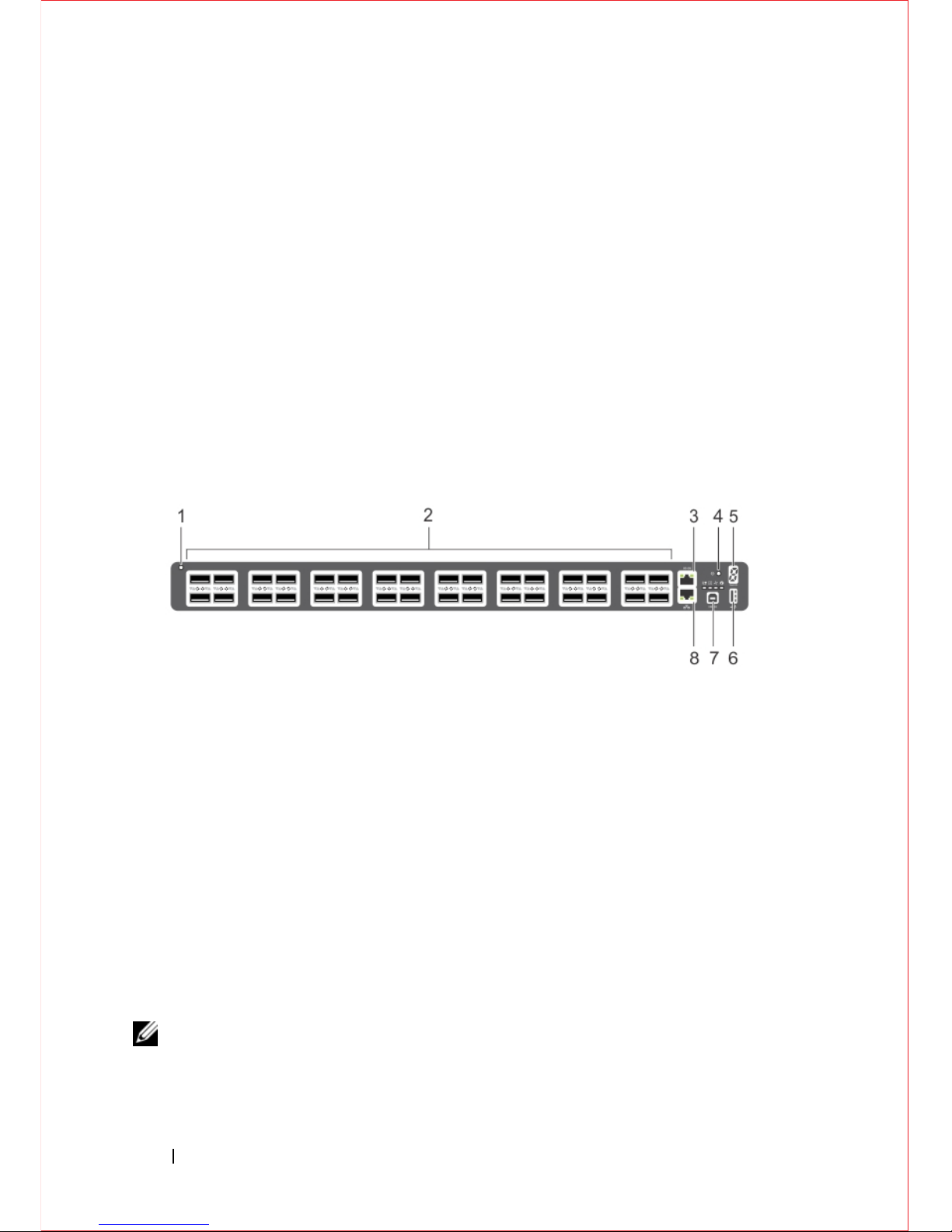
The I/O panel includes:
• Thirty-two fixed QSFP+ ports
• One USB-A 2.0 port
• One USB-B serial console port
• One RS-232 serial console port
• One 10/100/1000BaseT (RJ-45) Ethernet management port
Figure 3-1
shows the S6000 I/O panel.
Figure 3-1. S6000 I/O Panel
1 - System LED
2 - 32 QSFP+ Ports
3 - Serial Console
4 - Reset
5 - Stack ID
6 - USB-A
7 - USB-B Console
8 - Management
NOTE: The system light emitting diodes (LEDs) are on the I/O panel. The fan tray
power indicators are on the Utility panel.
Page 11
Hardware Overview 7
Utility Panel
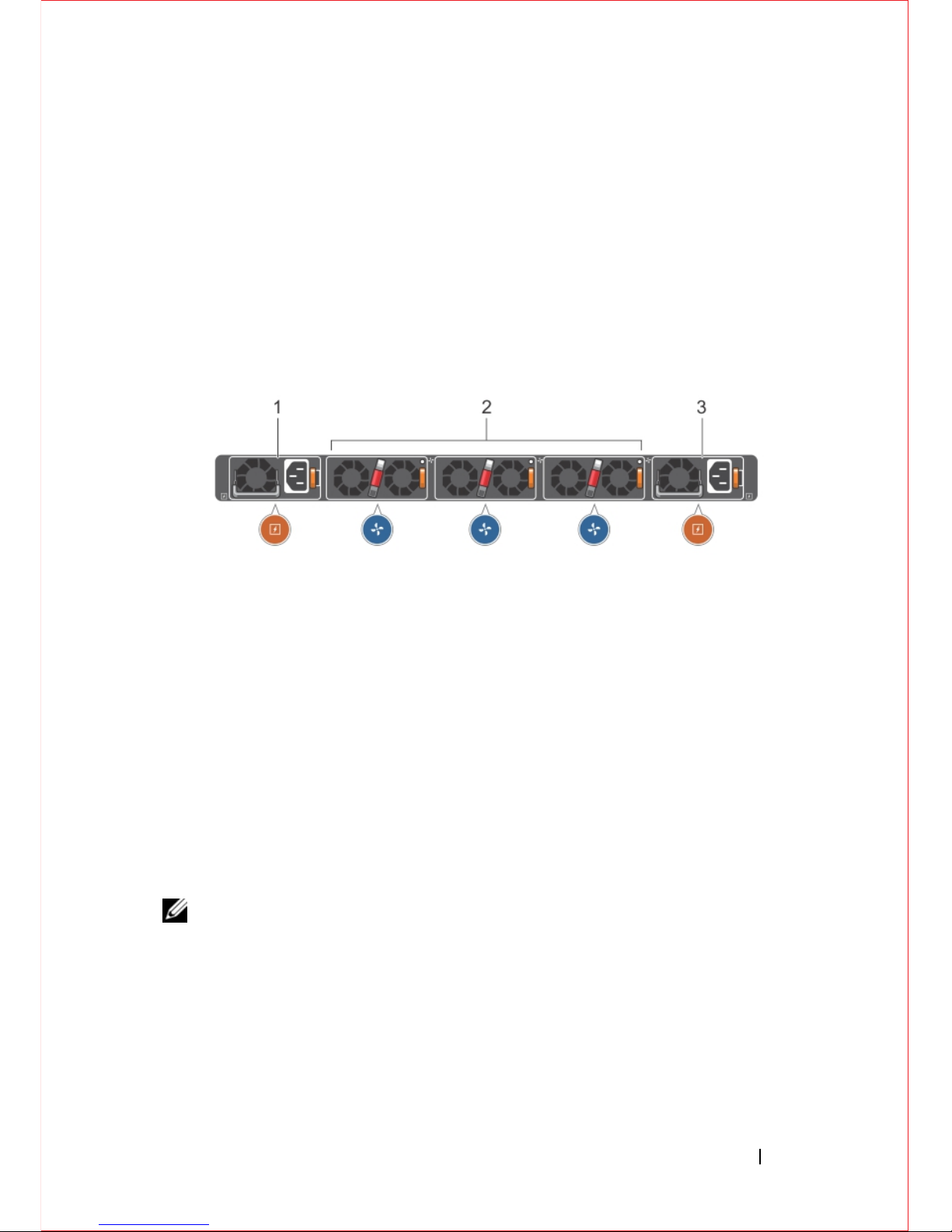
The Utility panel side contains the fan and power modules.
Figure 3-2
shows the
S6000 power supplies and fan modules.
Figure 3-2. S6000 Power Supplies and Fan Modules
1 - PSU 0
2 - Fan Modules 0-2
3 - PSU 1
Power Supplies
The S6000 supports two hot-swappable PSUs. The S6000 supports AC and DC
power supplies with two air-flow directions (I/O to PSU and PSU to I/O). Two
PSUs are required for full redundancy, but the system can operate with a single
PSU.
NOTE: If you use a single PSU, install a blank plate in the other PSU slot. Dell
Networking recommends using power supply 1 (PSU1) as the blank plate slot.
The PSUs are field replaceable. When running with full redundancy (two power
supplies installed and running), you can remove and replace one PSU while the
other PSU is running without disrupting traffic.
The S6000 does not support mixing PSU types. You cannot replace an AC PSU
with a DC PSU and you cannot replace an AC-R PSU with a DC-R PSU.
Page 12

8 Hardware Overview
WARNING: Electrostatic discharge (ESD) damage can occur if components
are mishandled. Always wear an ESD-preventive wrist or heel ground strap
when handling the S6000 and its components.
CAUTION: To prevent electrical shock, ensure the S6000 is grounded
properly. If you ground your equipment correctly, excessive emissions may
result. To ensure the power cables meet your local electrical requirements, use
a qualified electrician.
Fans
The S6000 supports three hot-swappable fans that provide cooling for the
system. The S6000 has stock keeping units (SKUs) that support the following
configurations. Installation of the fans is done as part of the factory install based
on SKU type. The PSUs are installed at the customer site (refer to
Power
Supplies
).
• AC PSU with fan airflow from I/O to PSU
• AC PSU with fan airflow from PSU to I/O
• DC PSU with fan airflow from I/O to PSU
• DC PSU with fan airflow from PSU to I/O
All fans and PSUs in a configuration must be in the same airflow direction.
Should a mixed airflow configuration happen, the software notifies you of the
invalid configuration.
The S6000 supports three fan trays with airflow directions from I/O to Utility or
Utility to I/O. The PSU airflow directions are indicated with stickers on PSUs.
Page 13
Hardware Overview 9
System Status
You can view S6000 status information in several ways, including LEDs and
boot menu options. You can also view status information through the command
line interface (CLI) show commands and with simple network management
protocol (SNMP). For more information about these options, refer to the FTOS
Command Line Reference Guide and FTOS Configuration Guide for the S6000
System.
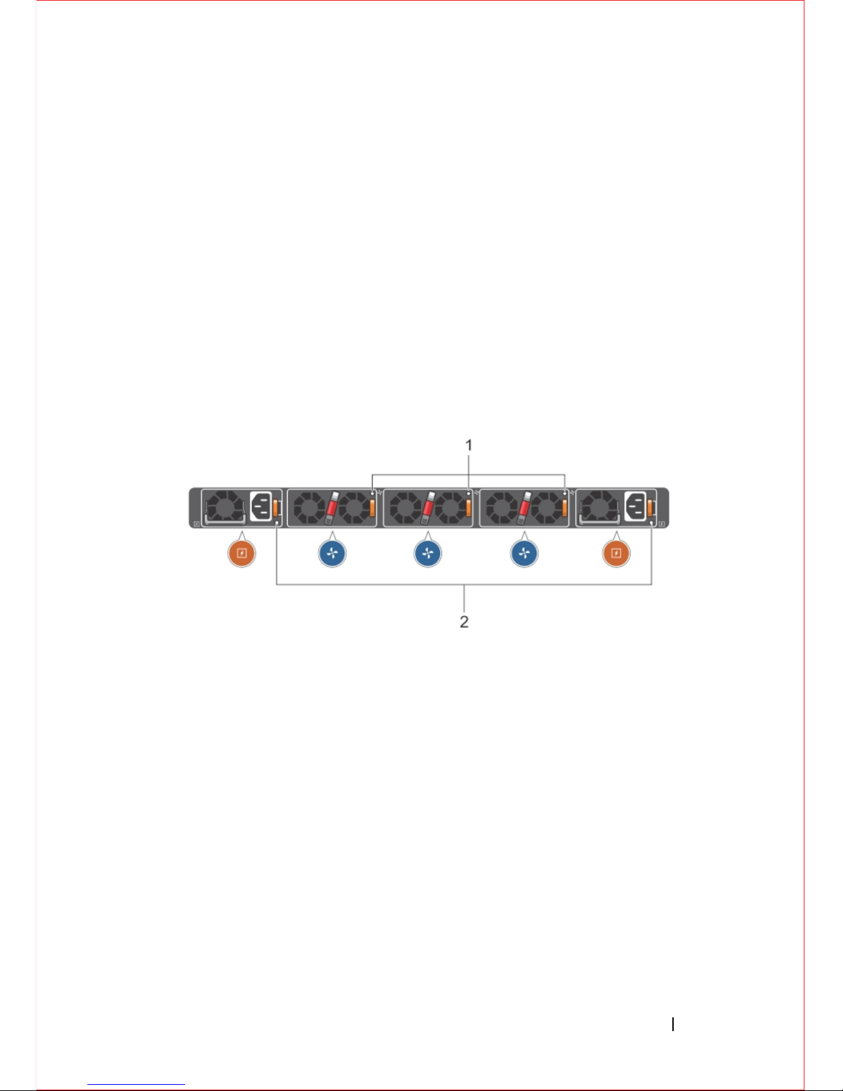
As shown in
Figure 3-3
, the S6000 includes LED displays on both the I/O and
PSU side of the chassis.
Figure 3-3. S6000 PSU and Fan Tray LEDs
1- Fan Tray 0-2 LEDs
2 - PSU 0-1 LEDs
Page 14
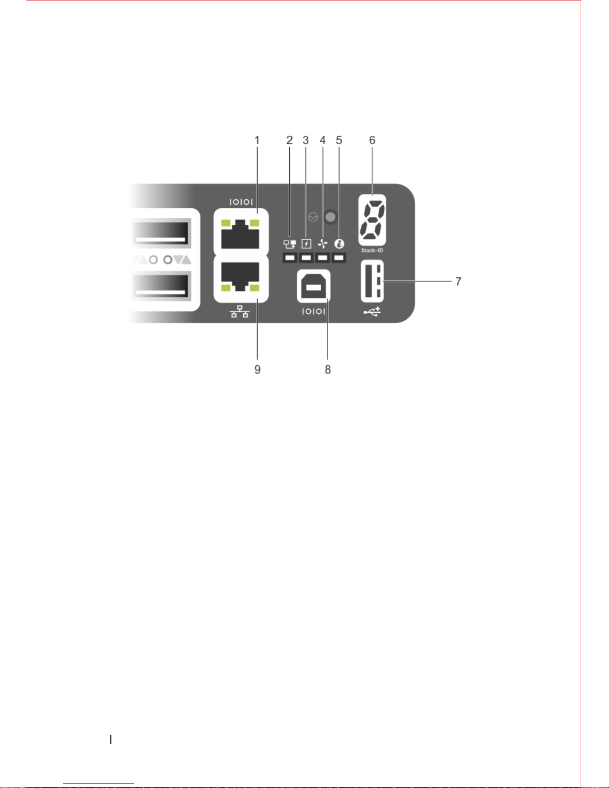
10 Hardware Overview
1 - Serial Console
2 - Master LED
3 - Power LED
4 - Fan Status LED
5 - Locator LED
6 - Stack ID
7 - USB-A
8 - USB-B Console
9 - Management
Table 3-1
lists the LED definitions for the S6000 system. This includes system,
PSU, and fan status.
Page 15

Hardware Overview 11
NOTE: When one of the FAN LEDs on the utility side indicates failure, the fan
LED on the I/O panel displays yellow.
Table 3-1. System LED indicators
Feature Detailed Description Comment
System LED
• Solid green–Normal operation. CLI
prompt available
• Blinking green–Boot-up in progress
• Solid yellow–Major Fault. Displays
summary of all major faults within the
system; the faults are traffic affecting
• Blinking yellow–Minor Fault. Displays
summary of all minor faults within the
system; the faults are not traffic affecting
I/O side
Power LED
•Off–No power
• Solid Yellow–POST in progress
• Solid green–Normal operation (dual or
single supply)
• Blinking yellow–One of the power
supplies has failed
I/O side
FAN LED
• Solid green–Fan powered and running at
the expected rpm
• Solid yellow–Fan failed including
incompatible airflow direction when PSU
or fan trays of differing airflows are
inserted in the same chassis
I/O side
MASTER LED
• Solid green–System in stacking Master
mode
• Off – Switch in Slave mode
I/O side
LOCATOR LED
• Off – No power
• Blinking blue – Locator function is
enabled
• Off – Locator function is disabled
I/O side
7-DIGIT Stack LED It indicates a number for stacking. I/O side
Page 16

12 Hardware Overview
The S6000 supports splitting a single 40G QSFP+ port into four 10G SFP+ ports
using one of the supported breakout cables. When you use the fanout feature, the
40G QSFP+ port is deleted and four10G SFP+ ports are created.
QSFP+ ports have eight LEDs associated with each stack of two ports; four for
the top and four for the bottom ports. You can configure each port as a single
40G port or four10G ports. When configured as a 40G port, only the first of the
four LEDs is used. When configured as four 10G ports, all four LEDs are used
to indicate the status.
Table 3-2
lists the LED status.
Table 3-2. 40G QSFP+/ 4x10G SFP+ Ethernet Port LEDs
Table 3-3. Management Ethernet Port LEDs
Feature Detailed Description
Link/Activity LED
• Off – No Link
• Blinking green – Transmit/Receive is active
• Solid green – Link up at 40Gbps/10Gbps speed
Feature Detailed Description
Link LED
• Off – No Link
• Solid green –Link on 10/100M/1G speed
Activity LED
• Off – No Link
• Blinking green – Transmit/Receive is active
Page 17
Installation 13
4
Installation
Unpacking the Switch
This section describes the package contents and the steps to unpack the S6000
switch.
Package Contents
When unpacking each switch, make sure that the following items are included:
• One S6000 switch
• One RJ-45 to DB-9 female cable
• Two sets of rail kits (no tools required)
• Two PSUs
• One AC power cord (country/region specific)
• Getting Started Guide
• Safety and Regulatory Information
• Warranty and Support Information
• Software License Agreement
Unpacking Steps
NOTE: Before unpacking the switch, inspect the container and immediately report
any evidence of damage.
Step Task
1
Place the container on a clean, flat surface and cut all straps securing the container .
2
Open the container or remove the container top.
3
Carefully remove the switch from the container and place it on a secure and clean
surface.
4
Remove all packing material.
5
Inspect the product and accessories for damage.
Page 18
14 Installation
Installing an AC or DC Power Supply
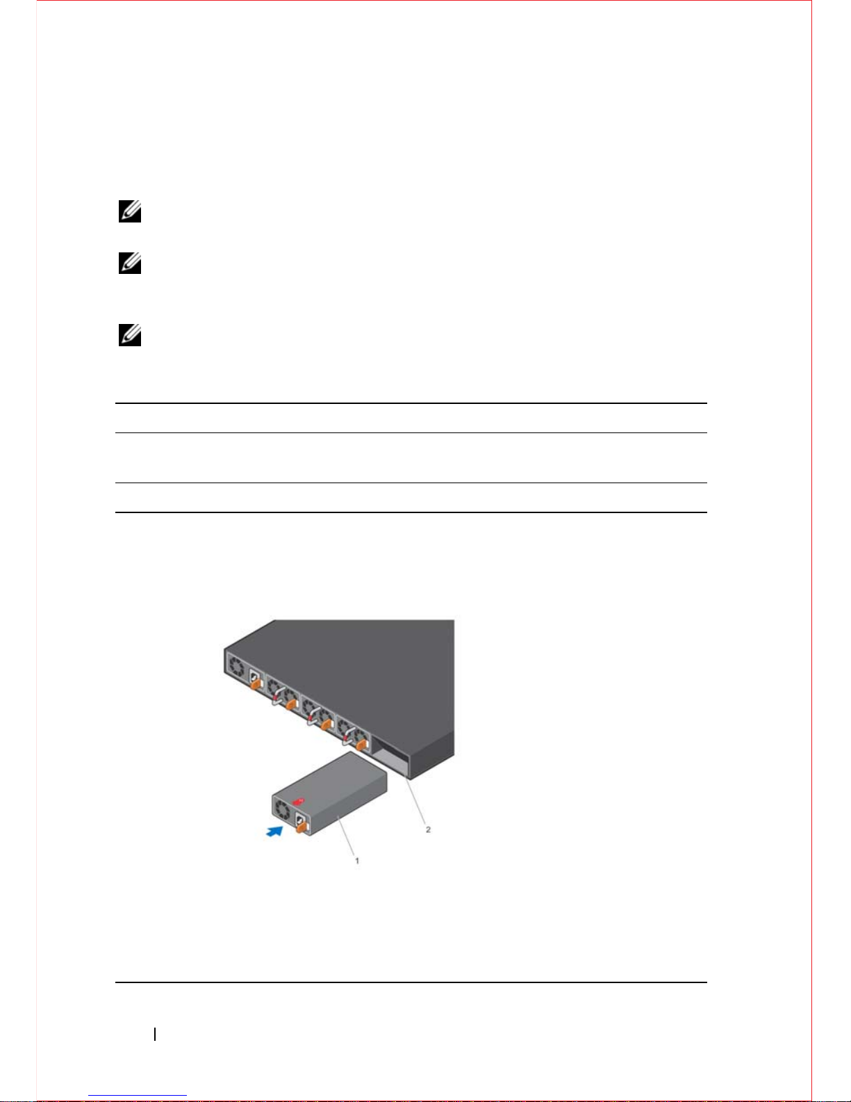
To install an AC or DC power supply, follow these steps.
NOTE: The PSU slides into the slot smoothly. Do not force the PSU into a slot as
this may damage the PSU or the S6000 chassis.
NOTE: Ensure that the PSU is correctly installed. When the PSU is correctly
installed, the power connector is on the left side of the PSU and the status LED is at
the bottom of the PSU.
NOTE: If you use a single PSU, install a blank plate in the other PSU slot. Dell
Networking recommends using power supply 1 (PSU1) as the blank plate slot.
Step Task
1 Remove the PSU slot cover from the S6000 (the PSU side of switch). You may
select either of the two PSU slots.
2 Remove the PSU from the electro-static bag.
3 Insert the PSU into the switch PSU slot (insert the PSU exposed PCB edge
connector first).
The PSU slot is keyed such that the PSU can only be fully inserted in one
orientation.
1 - Slot 1
2 - PSU1
When the PSU is installed correctly, it snaps into place and is flushed with the
back of the switch.
Page 19
Installation 15
NOTE: The system powers up as soon as the cables are connected between the
power supply and the power source.
Rack Mount the Switch
You may either place the switch on the rack shelf or mount the switch directly
into a 19" wide, EIA-310-E-compliant rack (four-post, two-post, or threaded
methods). The Dell ReadyRails™ system is provided for 1U front-rack, and
two-post installations. The ReadyRails system includes two separately packaged
rail assemblies and two rails that are shipped attached to the sides of the switch.
WARNING: This is a condensed reference. Read the safety instructions in your
Safety, Environmental, and Regulatory information booklet before you begin.
CAUTION: Do not use the mounted Ready-Rails as a shelf or a workplace.
NOTE: The illustrations in this document are not intended to represent a specific
switch.
Rack Mounting Safety Considerations
• Rack loading — Overloading or uneven loading of racks may result in shelf
or rack failure, causing damage to the equipment and possible personal
injury. Stabilize racks in a permanent location before loading begins. Mount
the components beginning at the bottom of the rack, then work to the top.
Do not exceed your rack load rating.
• Power considerations — Connect only to the power source specified on the
unit. When you install multiple electrical components in a rack, ensure that
the total component power ratings do not exceed the circuit capabilities.
Overloaded power sources and extension cords present fire and shock
hazards.
4 Plug in the appropriate cord (AC 3 prong or DC wiring) from the switch PSU to
the external power source (either an AC wall outlet or a DC rack bus bar).
5 If you have a redundant PSU (a second PSU), repeat steps 1 through 4 above
using the second PSU slot on the S6000 switch.
Step Task (continued)
Page 20

16 Installation
• Elevated ambient temperature — If installed in a closed rack assembly, the
operating temperature of the rack environment may be greater than the room
ambient temperature. Use care not to exceed the 40°C maximum ambient
temperature of the switch.
• Reduced air flow — Install the equipment in the rack so that the amount of
airflow required for safe operation of the equipment is not compromised.
• Reliable earthing — Maintain reliable earthing of rack-mounted equipment.
Pay particular attention to the supply connections other than the direct
connections to the branch circuit; for example, use of power strips.
• Do not mount the equipment with the rear panel facing in the downward
position.
Installing the Dell ReadyRails System
The ReadyRails rack mounting system is provided to easily configure your rack
for installation of your switch. You can install the ReadyRails system using the
1U tool-less method or one of three possible 1U tooled methods (two-post flush
mount, two-post center mount, or four-post threaded).
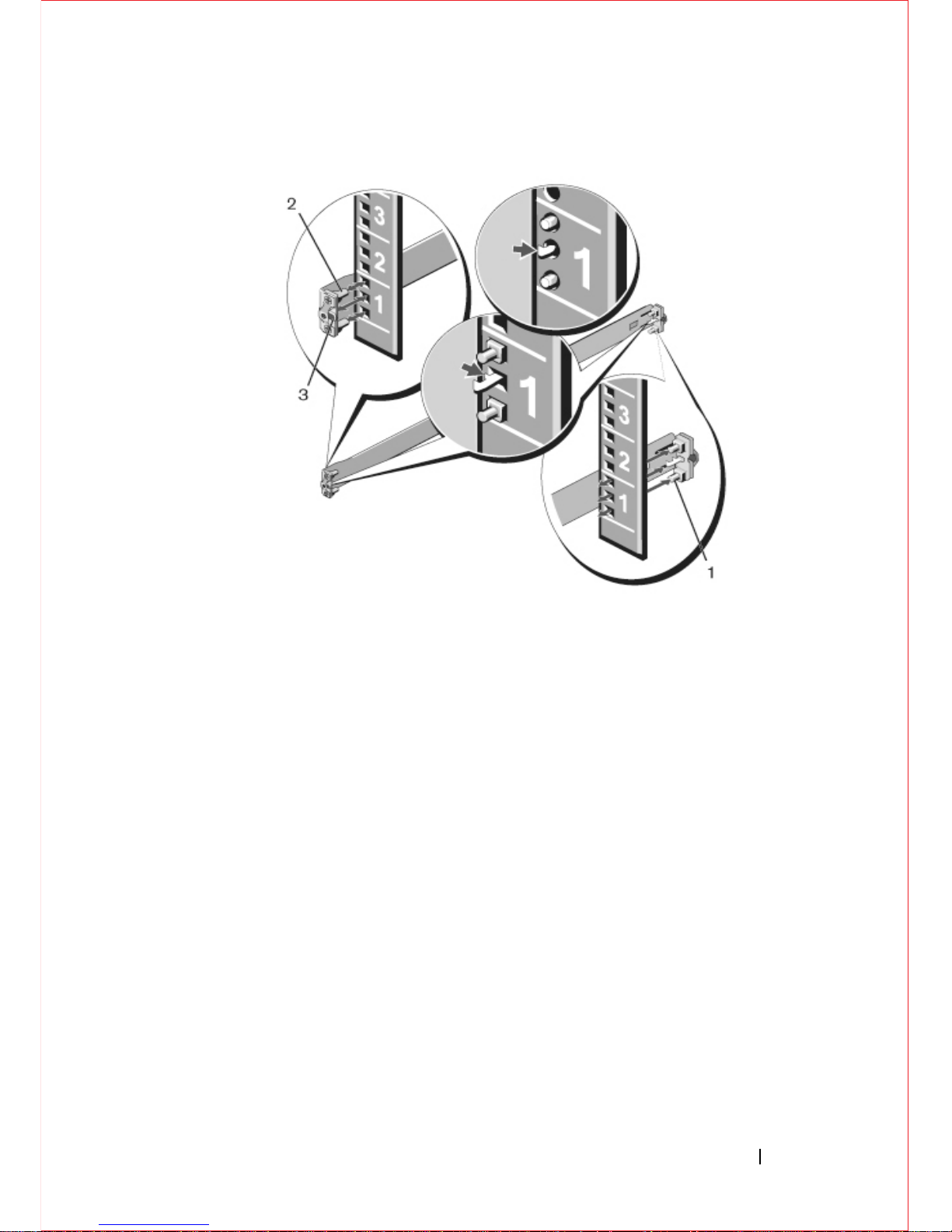
1U Tool-less Configuration (Four-Post Square Hole or Unthreaded Round Hole):
1
With the ReadyRails flange ears facing outward, place one rail between the
left and right vertical posts. Align and seat the rear flange rail pegs in the rear
vertical post flange. In Figure 4-1, item 1 shows how the pegs appear in both
the square and unthreaded round holes.
Page 21
Installation 17
Figure 4-1. 1U Tool-less Configuration
2
Align and seat the front flange pegs in the holes on the front side of the
vertical post. Refer to Figure 4-1, item 2.
3
Repeat this procedure for the second rail.
4
To remove each rail, pull on the latch release button on each flange ear and
unseat each rail. Refer to Figure 4-1, item 3.
Page 22
18 Installation
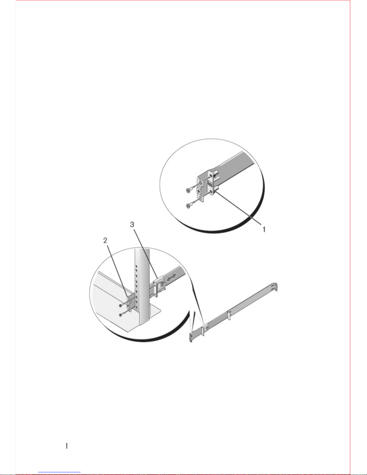
Two-Post Flush-Mount Configuration:
1
For this configuration, remove the castings from the front side of each
ReadyRails assembly. Refer to Figure 4-2, item 1. Use a Torx driver to
remove the two screws from each front flange ear (on the switch side of the
rail) and remove each casting. Retain the castings for future rack
requirements. It is not necessary to remove the rear flange castings.
Figure 4-2. Two-Post Flush-Mount Configuration
2
Attach one rail to the front post flange with two user-supplied screws. Refer
to Figure 4-2, item 2.
3
Slide the plunger bracket forward against the vertical post and secure the
plunger bracket to the post flange with two user-supplied screws. Refer
to Figure 4-2, item 3.
4
Repeat this procedure for the second rail.
Page 23
Installation 19
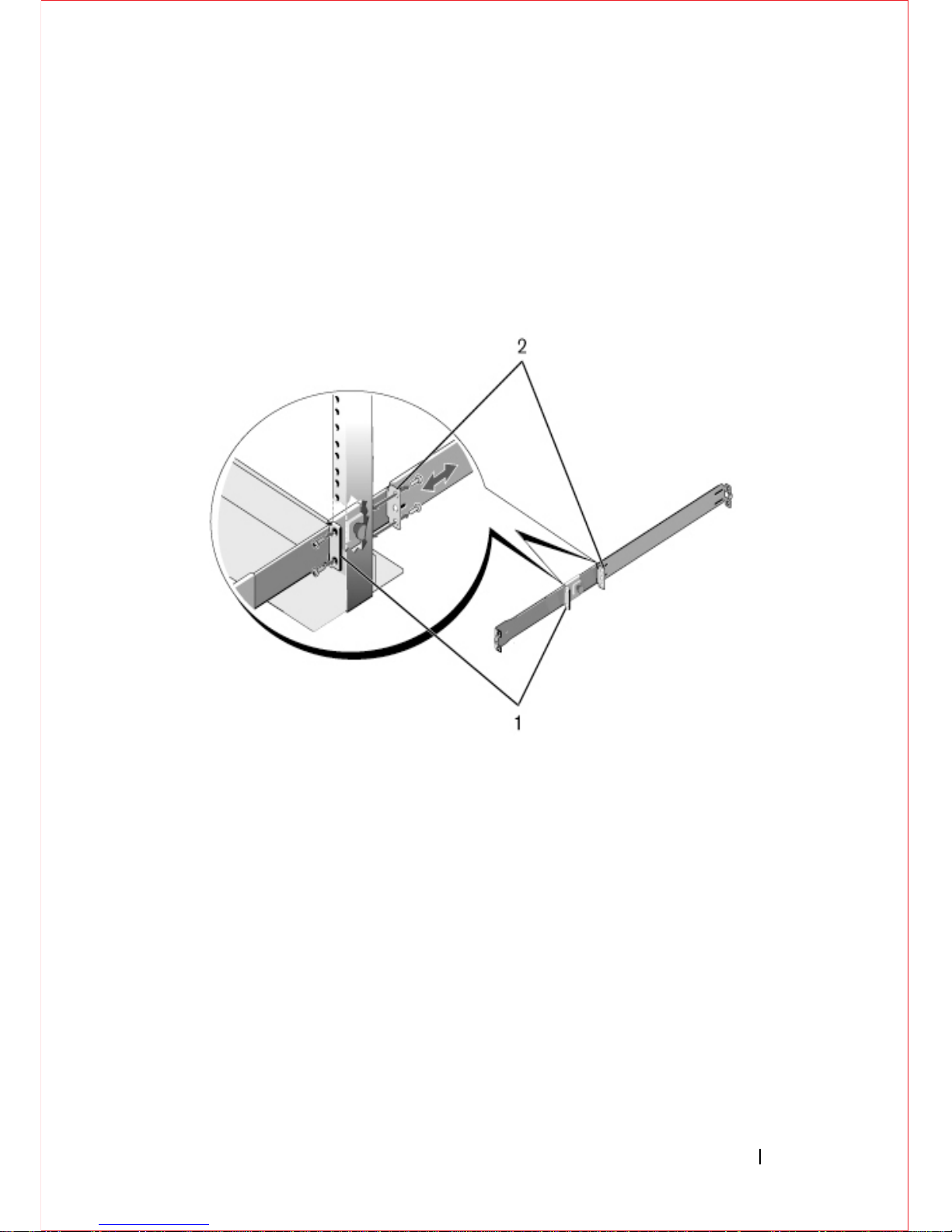
Two-Post Center-Mount Configuration:
1
Slide the plunger bracket rearward until it clicks into place and secure the
bracket to the front post flange with two user-supplied screws. Refer
to Figure 4-3, item 1.
Figure 4-3. Two-Post Center-Mount Configuration
2
Slide the back bracket towards the post and secure it to the post flange with
two user-supplied screws. Refer to Figure 4-3, item 2.
3
Repeat this procedure for the second rail.
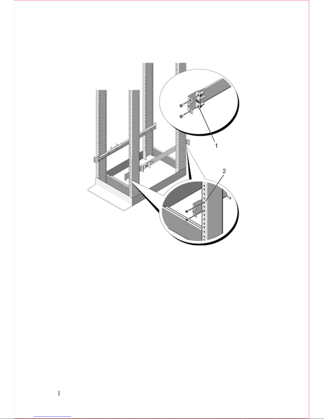
Four-Post Threaded Configuration:
1
For this configuration, remove the flange ear castings from each end of the
ReadyRails assemblies. Use a Torx driver to remove the two screws from
each flange ear and remove each casting. Refer to Figure 4-4, item 1. Retain
the castings for future rack requirements.
2
For each rail, attach the front and rear flanges to the post flanges with two
user-supplied screws at each end. Refer to Figure 4-4, item 2.
Page 24
20 Installation
Figure 4-4. Four-Post Threaded Configuration
Installing the Switch
You can mount the switch in the 1U front-rack or 1U two-post (flush and center)
configurations. The following is an example of a 1U front-rack configuration.
For the 1U two-post (flush and center) configurations, slide the switch into the
rails in the same manner as the four-post configurations.
1U Front-Rack Installation
Configure the rails that are attached to the switch.
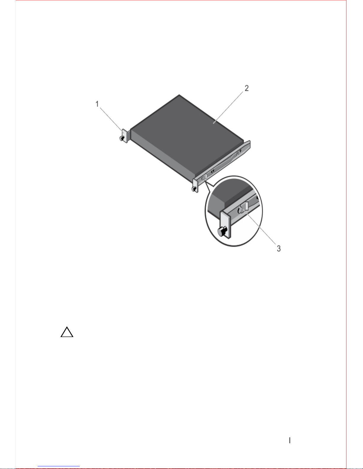
1
Attach the switch rails (inner chassis members) to the S6000 switch.
Figure 4-5, item 3 shows the detail for the front standoff with the locking tab.
Page 25
Installation 21
Figure 4-5. Attaching the Switch Rails
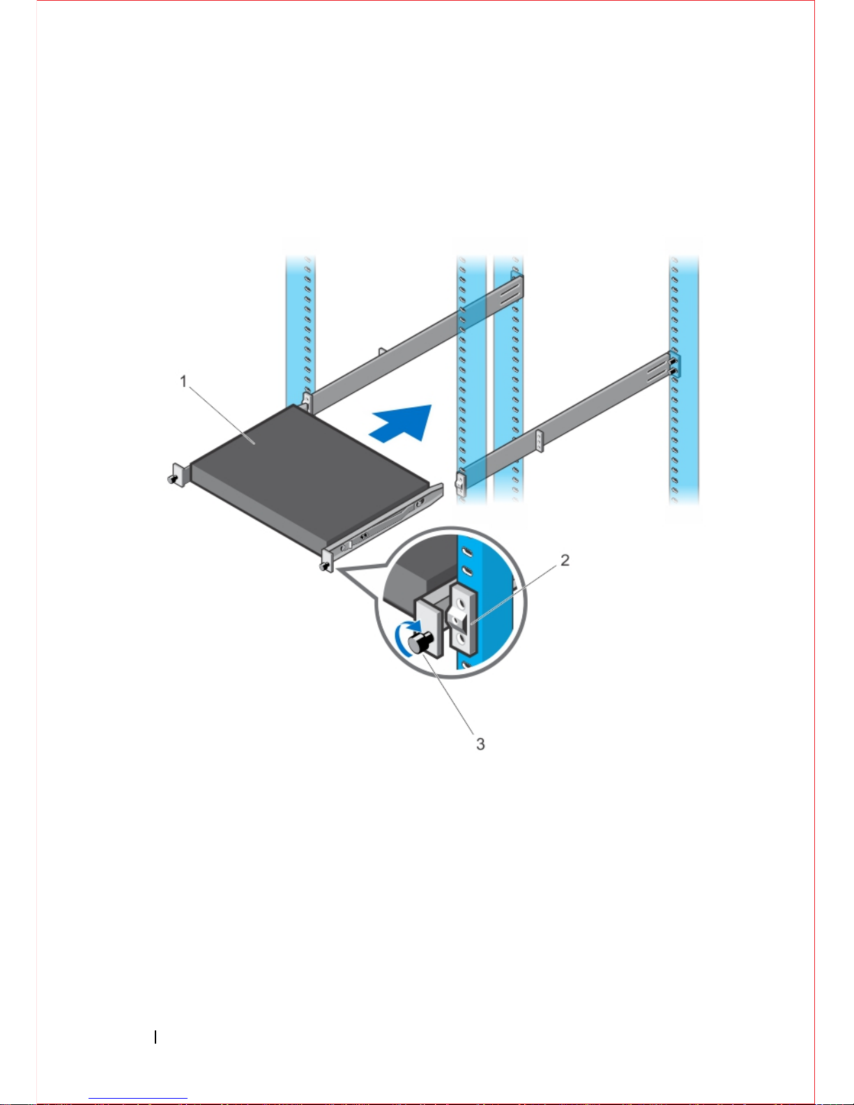
2
After you install both switch rails, line them up on the previously mounted
Ready-Rails and slide the switch in until it is flush with front of rack. About
three inches prior to full insertion, the rail locking feature engages to keep the
switch from inadvertently sliding out of the rack and falling. Refer to
Figure 4-6.
CAUTION: Do not use the mounted Ready-Rails as a shelf or a workplace.
Page 26
22 Installation
Figure 4-6. Front Rack Installation
Page 27
Technical Specifications 23
5
Technical Specifications
Operate the product at an ambient temperature not higher than 40°C.
Lithium Battery Caution: There is a danger of explosion if the battery is
incorrectly replaced.
Replace only with same or equivalent type. Dispose of the
batteries according to the manufacturer's instructions.
Chassis Physical Design
Environmental Parameters
Parameter Specifications
Height 1.71 inches (
43.5 mm
)
Width
17.09
inches (
434
mm)
Depth 18.11 inches (460 mm)
Parameter Specifications
Operating temperature 32° to 113°F (0° to 45°C)
Operating humidity 5 to 90% (RH), non-condensing
Storage temperature –40° to 158°F (–40° to 70°C)
Storage humidity 5 to 90% (RH), non-condensing
Maximum thermal output 419.7 BTU/hr
Page 28

24 Technical Specifications
Power Requirements
Parameter Specifications
Power supply 100–240 VAC 50/60 Hz
Maximum current draw per system 2.9 A @ 286 watts/100vac
1.4 A @ 286 watts/200vac
Maximum power consumption 286 Watts
Reliability MTBF 355,178 hours
Page 29
Installing the Software 25
6
Installing the Software
Navigating CLI Modes
The FTOS prompt changes to indicate the CLI mode. You must move linearly
through the command modes, with the exception of the end command which
takes you directly to EXEC Privilege mode and the exit command which moves
you up one command mode level.
Console Access
NOTE: You must have a password configured on a virtual terminal line before you
can Telnet into the S6000 system. Therefore, use a console connection when
connecting to the system for the first time. Before starting this procedure, be sure
you have a terminal emulation program already installed on your PC.
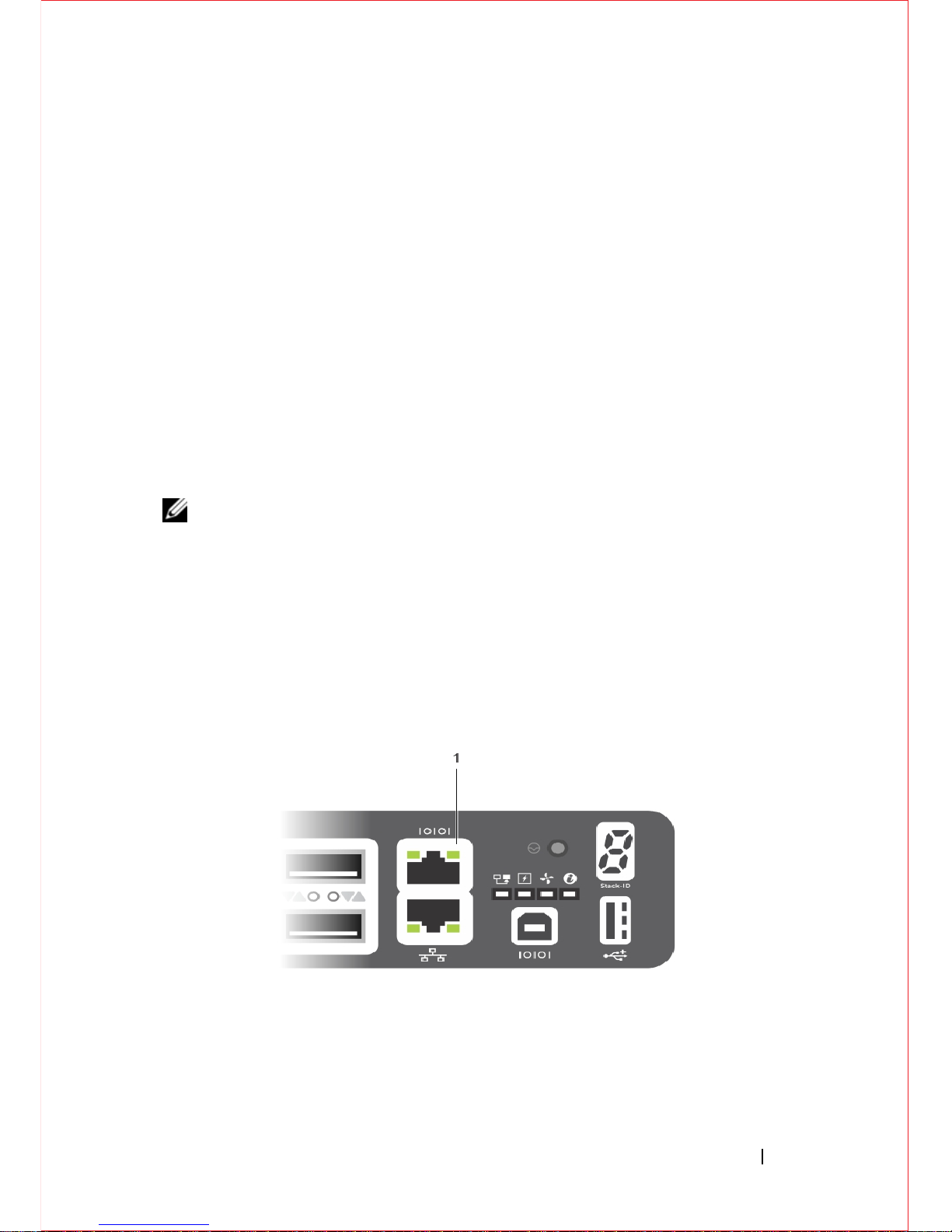
The RS-232 console port is labeled on the upper right-hand side of the S6000
system as you face the input/output (I/O) side of the chassis (
Figure 6-1
).
Figure 6-1. RS-232 Console Port
1- RS-232 console port
Page 30

26 Installing the Software
To set up the RS-232 console port, follow these steps.
Accessing the RJ-45 Console Port with a DB-9 Adapter
If the DTE has a DB-9 interface, you can connect to the console using an RJ-45
to DB-9 adapter along with the RJ-45 rollover cable.
Table 6-1
lists the pin
assignments.
Step Task
1 Install an RJ-45 copper cable into the console port. Use a rollover cable to
connect the S6000 console port to a terminal server.
2 Connect the other end of the cable to the DTE terminal server.
3 Set the default terminal settings as follows:
• 9600 baud rate
• No parity
• 8 data bits
• 1 stop bit
• No flow control
Table 6-1. Pin Assignments Between the Console and a DTE Terminal Server
Console Port RJ-45 to RJ-45 Rollover Cable RJ-45 to DB-9
Adapter
Terminal Server
Device
Signal RJ-45 Pinout RJ-45 Pinout DB-9 Pin Signal
RTS 1 8 8 CTS
NC 2 7 6 DSR
TxD 3 6 2 RxD
GND 4 5 5 GND
GND 5 4 5 GND
RxD 6 3 3 TxD
NC 7 2 4 DTR
CTS 8 1 7 RTS
Page 31

Installing the Software 27
Default Configuration
A version of FTOS is pre-loaded onto the S6000 system; however, the system is not
configured when you power up for the first time (except for the default host name, which
is
FTOS). You must configure the system using the CLI.
Configuring Layer 2 (Data Link) Mode
To enable Layer 2 data transmissions through an individual interface, use the
switchport command in INTERF ACE mode. You cannot configure switching or
Layer 2 protocols such as spanning tree protocol (STP) on an interface unless
the interface has been set to Layer 2 mode.
To configure Layer 2 mode, follow these steps.
To view the interfaces in Layer 2 mode, use the show interfaces switchport
command in EXEC mode.
Configuring a Host Name
The host name appears in the prompt. The default host name is FTOS. Host
names must start with a letter, end with a letter or digit, and must have
characters, letters, digits, and hyphens in the string.
To configure a host name, follow this step.
Step Task Command Syntax Command Mode
1 Enable the interface. no shutdown INTERFACE
2 Place the interface in
Layer 2 (switching)
mode.
switchport INTERFACE
Task Command Syntax Command Mode
Create a new host name. hostname name CONFIGURATION
Page 32

28 Installing the Software
Accessing the System Remotely
You can configure the S6000 system to be accessed remotely by Telnet. The
system has a dedicated management port and a management routing table that is
separate from the IP routing table.
To access the system remotely, follow these steps.
Configuring the Management Port IP Address
In order to access the system remotely, assign IP addresses to the management
ports.
To assign IP addresses to the management ports, follow these steps.
Step Task
1 Configure an IP address for the management port (
Configuring the Management
Port IP Address
).
2 Configure a management route with a default gateway (
Configuring the
Management Route
).
3 Configure a username and password (
Configuring the Username and Password
).
Step Task Command Syntax Command Mode
1 Enter INTERFACE
mode for the
Management port.
interface ManagementEthernet
slot/port
CONFIGURATION
2 Assign an IP address
to the interface.
ip address ip-address/mask INTERFACE
3 Enable the interface. no shutdown INTERFACE
Page 33

Installing the Software 29
Configuring the Management Route
Define a path from the S6000 to the network from which you are accessing the
S6000 remotely . Management routes are separate from IP routes and are used to
manage the S6000 through the management port.
To configure a management route, follow this step.
Configuring the Username and Password
To access the system remotely, configure a system username and password.
To configure a username and password, follow this step.
Configuring the Enable Password
Access EXEC Privilege mode using the enable command. EXEC Privilege
mode is unrestricted by default. As a basic security measure, configure a
password. There are two types of enable passwords:
• enable password — stores the password in the running/startup configuration
using a data encryption standard (DES)-encryption method.
• enable secret — stores the password in the running/startup configuration
using a stronger, MD5-encryption method.
Dell Networking recommends using the enable secret password.
Task Command Syntax Command Mode
Configure a
management route to
the network from
which you are
accessing the system.
management route ip-address/mask
gateway
CONFIGURATION
Task Command Syntax Command Mode
Configure a username
and password to
access the system
remotely.
username username password
[encryption-type]
CONFIGURATION
Page 34

30 Installing the Software
To configure the enable secret password, follow this step.
Creating a Port-based VLAN
The default VLAN (VLAN 1) is part of the system startup configuration and
does not require configuration. To configure a port-based VLAN, create the
VLAN and then add physical interfaces or port channel (LAG) interfaces to the
VLAN.
To create a port-based VLAN, follow this step.
To view the configured VLANs, use the show vlan command in EXEC
Privilege mode.
Assigning Interfaces to a VLAN
You can only assign interfaces in Layer 2 mode to a VLAN using the tagged and
untagged commands. To place an interface in Layer 2 mode, use the switchport
command.
You can designate Layer 2 interfaces as tagged or untagged. When you place an
interface in Layer 2 mode using the switchport command, the interface is
automatically designated untagged and placed in the Default VLAN.
Task Command Syntax Command Mode
Create a password to
access EXEC
Privilege mode.
enable [password | secret] [level level]
[encryption-type] password
CONFIGURATION
Task Command Syntax Command Mode
Configure a port-based VLAN (if the
vlan-id is different from the Default
VLAN ID) and enter INTERFACE
VLAN mode. After you create a
VLAN, you must assign interfaces in
Layer 2 mode to the VLAN to activate
the VLAN.
interface vlan vlan-id CONFIGURATION
Page 35

Installing the Software 31
To view which interfaces are tagged or untagged and to view which VLAN the
interfaces belong, use the show vlan command. To view just the interfaces that
are in Layer 2 mode, use the show interfaces switchport command in EXEC
Privilege mode or EXEC mode.
To tag frames leaving an interface in Layer 2 mode, assign that interface as
tagged to a port-based VLAN to tag it with that VLAN ID.
To tag interfaces, follow these steps.
T o move untagged interfaces from the Default VLAN to another VLAN, use the
untagged command:
To move untagged interfaces, follow these steps.
Step Task Command Syntax Command Mode
1 Access the
INTERFACE VLAN
mode of the VLAN to
which you want to
assign the interface.
interface vlan vlan-id CONFIGURATION
2 Enable an interface to
include the IEEE
802.1Q tag header.
This command is
available only in
VLAN interfaces.
tagged interface INTERFACE
Step Task Command Syntax Command Mode
1 Access the
INTERFACE VLAN
mode of the VLAN to
which you want to
assign the interface.
interface vlan vlan-id CONFIGURATION
2 Configure an interface
as untagged. This
command is available
only in VLAN
interfaces.
untagged interface INTERFACE
Page 36
32 Installing the Software
Assigning an IP Address to a VLAN
VLANs are a Layer 2 feature. For two physical interfaces on different VLANs
to communicate, assign an IP address to the VLANs to route traffic between the
two interfaces. The shutdown command in INTERFACE mode does not affect
Layer 2 traffic on the interface.
NOTE: You cannot assign an IP address to the Default VLAN, which, by default,
is VLAN 1. To assign another VLAN ID to the Default VLAN, use the default
vlan-id vlan-id command from the configuration mode.
To assign an IP address to a VLAN, follow this step.
Connecting the S6000 to the Network
After you have completed the hardware installation and software configuration
for the S6000 system, you can connect to your company network by following
your company’s cabling requirements.
Task Command Syntax Command Mode
Access the INTERFACE
VLAN mode of the
VLAN to which you want
to assign the IP address.
Configure an IP addresses
and mask on the interface.
ip address ip-address mask
[secondary]
INTERFACE
Page 37
www.dell.com | support.dell.com
Printed in the U.S.A.
 Loading...