

Page 1

Dell Precision M3800
Owner's Manual
Regulatory Model: P31F
Regulatory Type: P31F001
Page 2

Poznámky, upozornění a varování
POZNÁMKA POZNÁMKA označuje důležité informace, které umožňují lepší využití produktu.
VÝSTRAHA UPOZORNĚNÍ varuje před možným poškozením hardwaru nebo ztrátou dat a obsahuje pokyny, jak těmto
problémům předejít.
VAROVÁNÍ VAROVÁNÍ upozorňuje na potenciální poškození majetku a riziko úrazu nebo smrti.
Copyright © 2017 Dell Inc. nebo dceřiné společnosti. Všechna práva vyhrazena.Dell, EMC a ostatní ochranné známky jsou
ochranné známky společnosti Dell Inc. nebo dceřiných společností. Ostatní ochranné známky mohou být ochranné známky svých vlastníků.
2015 - 05
Rev. A02
Page 3

Contents
1 Manipulace uvnitř počítače............................................................................................................5
Před manipulací uvnitř počítače...........................................................................................................................................5
Vypnutí počítače....................................................................................................................................................................6
Po manipulaci uvnitř počítače.............................................................................................................................................. 6
2 Demontáž a instalace součástí....................................................................................................... 7
Doporučené nástroje............................................................................................................................................................. 7
System Overview...................................................................................................................................................................7
Removing the Base Cover....................................................................................................................................................8
Installing the Base Cover...................................................................................................................................................... 9
Removing the System Badge Flap...................................................................................................................................... 9
Installing the System Badge Flap....................................................................................................................................... 10
Removing the Battery......................................................................................................................................................... 10
Installing the Battery.............................................................................................................................................................11
Removing the Memory Module(s)......................................................................................................................................11
Installing the Memory Module(s)........................................................................................................................................11
Removing the Touchpad..................................................................................................................................................... 12
Installing the Touchpad........................................................................................................................................................12
Removing the Hard Drive....................................................................................................................................................13
Installing the Hard Drive...................................................................................................................................................... 13
Removing the Speakers .................................................................................................................................................14
Installing the Speakers.........................................................................................................................................................14
Removing the WLAN Card..................................................................................................................................................14
Installing the WLAN Card....................................................................................................................................................15
Removing the Coin-Cell Battery........................................................................................................................................ 15
Installing the Coin-Cell Battery...........................................................................................................................................16
Removing the mSATA Card................................................................................................................................................16
Installing the mSATA Card.................................................................................................................................................. 17
Removing the Fans ............................................................................................................................................................. 17
Installing the Fans.................................................................................................................................................................18
Removing the Heatsink....................................................................................................................................................... 18
Installing the Heatsink..........................................................................................................................................................19
Removing the Power Connector....................................................................................................................................... 19
Installing the Power Connector......................................................................................................................................... 20
Removing the Input/Output (I/O) Board........................................................................................................................ 20
Installing the I/O Board....................................................................................................................................................... 21
Removing the System Board..............................................................................................................................................21
Installing the System Board................................................................................................................................................23
Removing the Keyboard..................................................................................................................................................... 23
Installing the Keyboard........................................................................................................................................................25
Removing the Display Assembly .......................................................................................................................................25
Installing the Display Assembly...........................................................................................................................................27
Removing the Palmrest Assembly.....................................................................................................................................27
Installing the Palmrest Assembly....................................................................................................................................... 29
Contents 3
Page 4

3 Nastavení systému..................................................................................................................... 30
Boot Sequence.................................................................................................................................................................... 30
Navigační klávesy................................................................................................................................................................ 30
System Setup Options.........................................................................................................................................................31
Aktualizace systému BIOS v systému Windows .............................................................................................................33
Systémové heslo a heslo pro nastavení............................................................................................................................34
Nastavení systémového hesla a hesla pro nastavení................................................................................................34
Odstranění nebo změna stávajícího hesla k systému nebo nastavení.................................................................... 35
4 Diagnostika................................................................................................................................36
Rozšířená diagnostika vyhodnocení systému před jeho spuštěním (ePSA)................................................................ 36
Device Status Light.............................................................................................................................................................36
5 Technical Specifications............................................................................................................. 37
6 Kontaktování společnosti Dell......................................................................................................42
4 Contents
Page 5
1
Manipulace uvnitř počítače
Před manipulací uvnitř počítače
Řiďte se těmito bezpečnostními pokyny, které pomohou ochránit počítač před případným poškozením a zajistí vaši bezpečnost. Pokud není
uvedeno jinak, u každého postupu v tomto dokumentu se předpokládá splnění následujících podmínek:
• Přečetli jste si bezpečnostní informace dodané s počítačem.
• Součást je možné nahradit nebo (v případě zakoupení samostatně) nainstalovat pomocí postupu pro odebrání provedeném
v obráceném pořadí.
POZNÁMKA Před manipulací uvnitř počítače si přečtěte bezpečnostní pokyny dodané s počítačem. Další informace
o vzorových bezpečnostních postupech naleznete na stránkách www.dell.com/regulatory_compliance
VÝSTRAHA Mnohé z oprav smí provádět pouze certifikovaný servisní technik. Sami byste měli odstraňovat pouze menší
problémy a provádět jednoduché opravy, k nimž vás opravňuje dokumentace k produktu nebo k nimž vás
prostřednictvím internetu či telefonicky vyzve tým služeb a podpory. Na škody způsobené neoprávněným servisním
zásahem se nevztahuje záruka. Přečtěte si bezpečnostní pokyny dodané s produktem a dodržujte je.
VÝSTRAHA Aby nedošlo k elektrostatickému výboji, použijte uzemňovací náramek nebo se opakovaně dotýkejte
nenatřeného kovového povrchu (například konektoru na zadní straně počítače).
VÝSTRAHA Zacházejte se součástmi a kartami opatrně. Nedotýkejte se součástí ani kontaktů na kartě. Držte kartu za
okraje nebo za montážní svorku. Součásti, jako je například procesor, držte za okraje, ne za kolíky.
VÝSTRAHA Při odpojování kabelu vytahujte kabel za konektor nebo za vytahovací poutko, ne za vlastní kabel. Konektory
některých kabelů mají upevňovací západku. Pokud odpojujete tento typ kabelu, před jeho vytažením západku zmáčkněte.
Když oddělujete konektory od sebe, zarovnejte je tak, aby nedošlo k ohnutí kolíků. Také před připojením kabelu se
ujistěte, že jsou oba konektory správně zarovnané.
POZNÁMKA Barva počítače a některých součástí se může lišit od barev uvedených v tomto dokumentu.
Aby nedošlo k poškození počítače, před manipulací s vnitřními součástmi počítače proveďte následující kroky.
1. Ujistěte se, že je pracovní povrch rovný a čistý, aby nedošlo k poškrábání krytu počítače.
2. Vypněte počítač (Vypnutí počítače).
3. Pokud je počítač připojen k dokovacímu zařízení, například k volitelné multimediální základně nebo k externí baterii, odpojte jej.
VÝSTRAHA
zařízení.
4. Odpojte všechny síťové kabely od počítače.
5. Odpojte počítač a všechna připojená zařízení od elektrických zásuvek.
6. Zavřete displej a otočte počítač spodní stranou nahoru na plochý pracovní povrch.
POZNÁMKA
desky.
7. Vyjměte hlavní baterii.
8. Otočte počítač horní stranou nahoru.
9. Otevřete displej.
10. Stisknutím tlačítka napájení uzemněte základní desku.
VÝSTRAHA
elektrické zásuvky.
Při odpojování síťového kabelu nejprve odpojte kabel od počítače a potom jej odpojte od síťového
Před servisním zásahem uvnitř počítače je třeba vyjmout hlavní baterii, aby nedošlo k poškození základní
Aby nedošlo k úrazu elektrickým proudem, před otevřením krytu počítače vždy odpojte počítač od
Manipulace uvnitř počítače 5
Page 6
VÝSTRAHA Před manipulací s vnitřními součástmi počítače proveďte uzemnění tím, že se dotknete nenatřené kovové
plochy, jako například kovové části na zadní straně počítače. Během práce se opětovně dotýkejte nenatřeného
kovového povrchu, abyste vybili statickou elektřinu, která by mohla interní součásti počítače poškodit.
11. Vyjměte z příslušných slotů všechny nainstalované karty ExpressCard nebo čipové karty.
Vypnutí počítače
VÝSTRAHA Aby nedošlo ke ztrátě dat, před vypnutím počítače uložte a zavřete všechny otevřené soubory a ukončete
všechny spuštěné aplikace.
Počítač lze vypnout dvěma způsoby:
1. Použitím tlačítka napájení
2. Pomocí nabídky ovládacích tlačítek
Pomocí tlačítka napájení
1. Stisknutím a přidržením tlačítka Power vypněte obrazovku.
Pomocí ovládacích tlačítek
1. Potažením prstu od pravého okraje displeje vyvolejte nabídku Ovládací tlačítka.
2. Chcete-li vypnout počítač, stiskněte možnosti Settings —> Power —> Shut down (Vypnout).
Po manipulaci uvnitř počítače
Po dokončení montáže se ujistěte, že jsou připojena všechna externí zařízení, karty a kabely. Učiňte tak dříve, než zapnete počítač.
VÝSTRAHA
Dell. Nepoužívejte baterie vytvořené pro jiné počítače Dell.
1. Připojte veškerá externí zařízení, například replikátor portů, externí baterii nebo multimediální základnu, a nainstalujte všechny karty,
například kartu ExpressCard.
2. Připojte k počítači všechny telefonní nebo síťové kabely.
VÝSTRAHA
3. Vložte baterii.
4. Připojte počítač a všechna připojená zařízení do elektrických zásuvek.
5. Zapněte počítač.
Chcete-li se vyhnout poškození počítače, používejte pouze baterii, která byla vytvořena pro tento počítač
Chcete-li připojit síťový kabel, nejprve připojte kabel do síťového zařízení a teprve poté do počítače.
6
Manipulace uvnitř počítače
Page 7
Demontáž a instalace součástí
Doporučené nástroje
Postupy uvedené v tomto dokumentu mohou vyžadovat použití následujících nástrojů:
• malý plochý šroubovák,
• šroubovák Phillips #0,
• šroubovák Phillips #1,
• Šroubovák T5 Torx
• malá plastová jehla,
System Overview
2
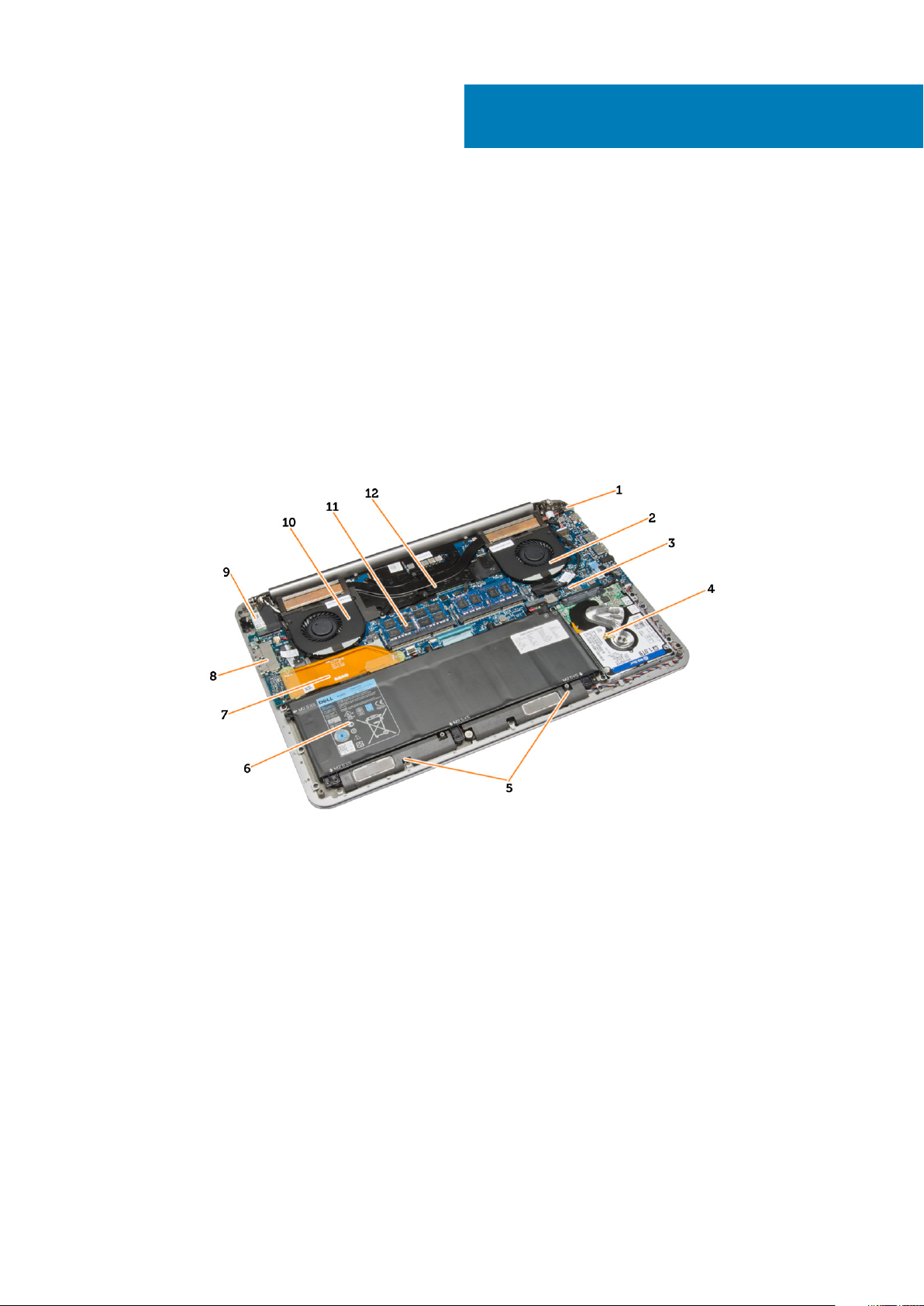
Figure 1. Inside View — Back
power connector 2. system fan
1.
3. system board 4. hard drive
5. speakers 6. battery
7. I/O board cable 8. I/O board
9. WLAN card 10. video-card fan
11. memory modules 12. heatsink
Demontáž a instalace součástí 7
Page 8
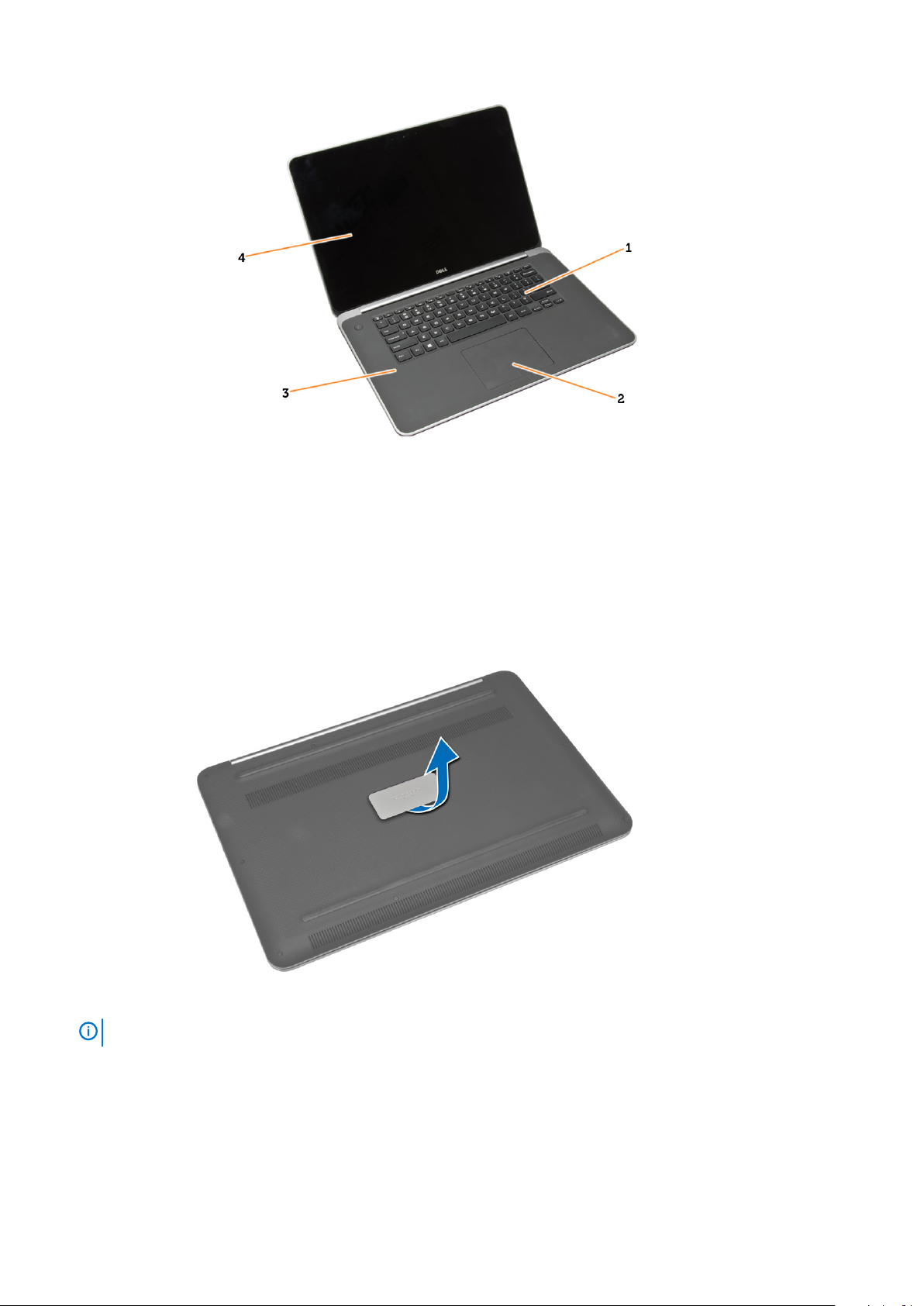
Figure 2. Front View
1. keyboard 2. touchpad
3. palmrest 4. display
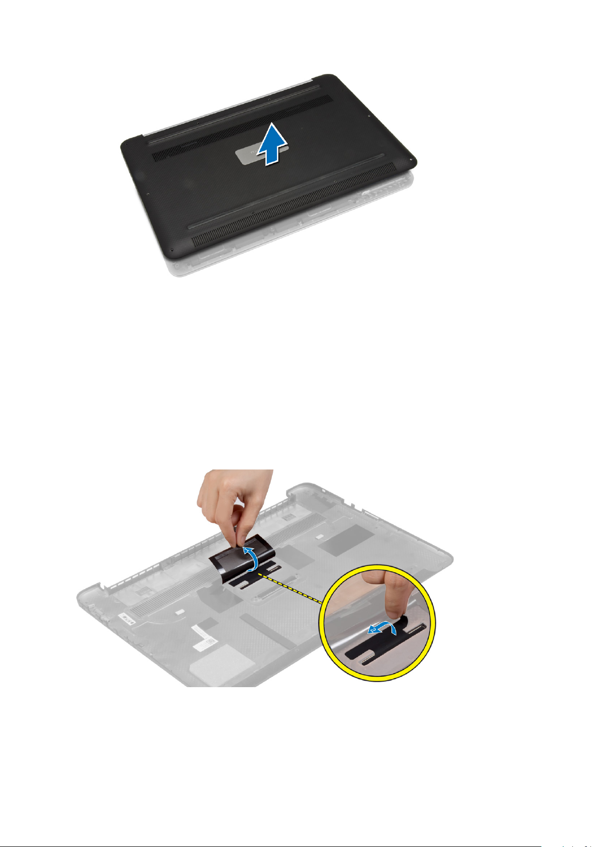
Removing the Base Cover
1. Follow the procedures in Before Working Inside Your Computer.
2. Close the display and turn the computer over.
3. Turn the system badge flap over and place it on the base cover.
4. Remove the screws that secure the base cover to the computer. Release and remove the base cover from the computer.
NOTE:
5. Lift up and remove the base cover from the computer.
8
To remove the screws from the base cover, use a T5 Torx screwdriver.
Demontáž a instalace součástí
Page 9
Installing the Base Cover
1. Place the base cover on the computer and snap it in place.
2. Tighten the screws to secure the base cover to the computer.
3. Turn the system badge flap over and snap it in place.
4. Follow the procedures in After Working Inside Your Computer.
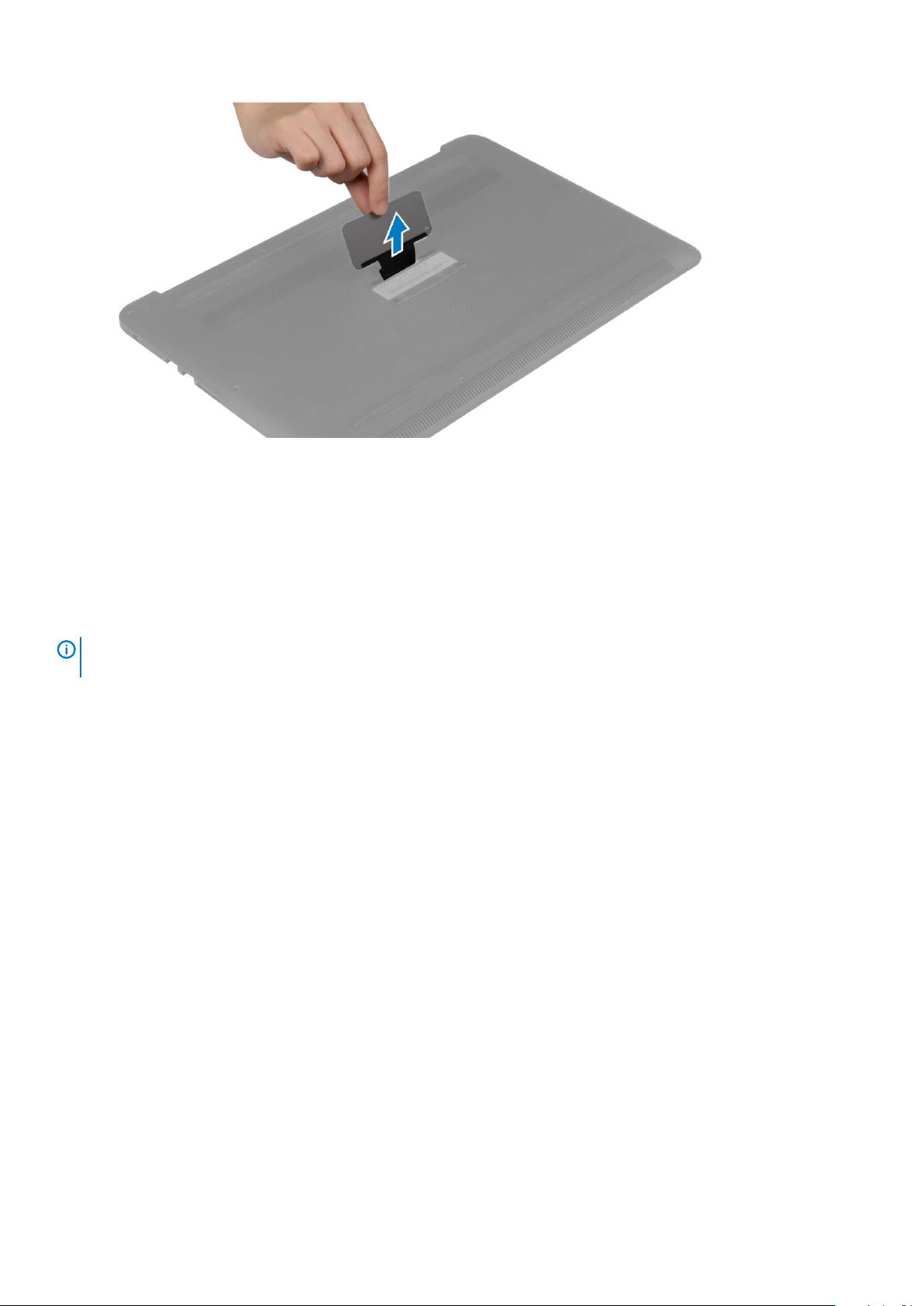
Removing the System Badge Flap
1. Follow the procedures in Before Working Inside Your Computer.
2. Remove the base cover.
3. Turn over the base cover and peel the Mylar tape that secures the system badge flap to the base cover.
4. Flip the base cover and release the tab on the system badge flap from the slot on the base cover. Lift the system badge flap off the
base cover.
Demontáž a instalace součástí
9
Page 10
Installing the System Badge Flap
1. Slide the tab on the system badge flap into the slot on the base cover and snap the system badge flap into place.
2. Turn the base cover over and affix the Mylar tape that secures the system badge flap to the base cover.
3. Follow the procedures in After Working Inside Your Computer.
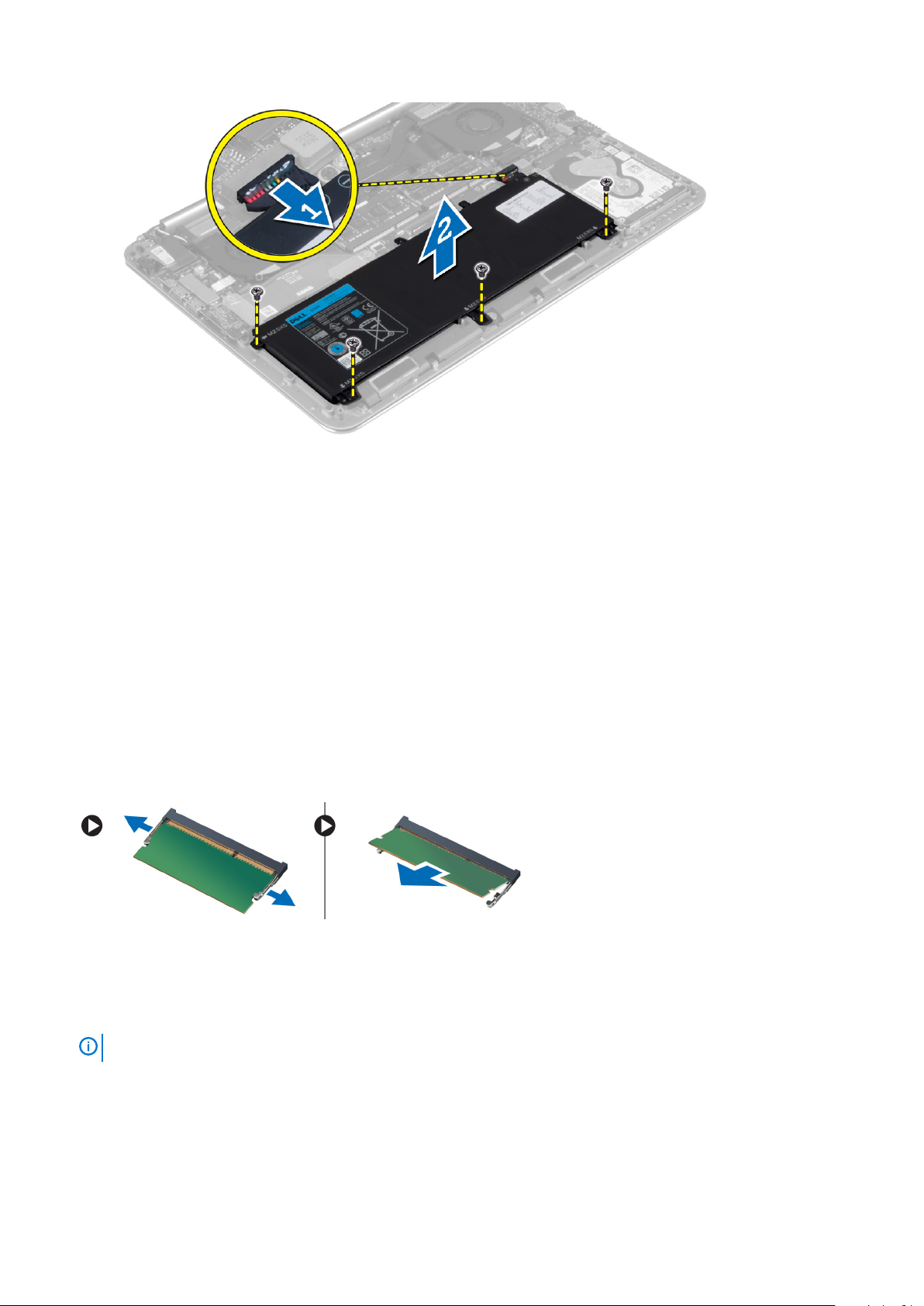
Removing the Battery
NOTE:
the A/C adapter from the system (while the system is turned on) to allow the system to drain the battery.
1. Follow the procedures in Before Working Inside Your Computer.
2. Remove the base cover.
3. Perform the following steps to remove the battery:
a) Disconnect the battery cable from the system board [1].
b) Remove the screws that secure the battery to the computer.
c) Lift the battery off the computer [2].
• Do not apply pressure to the surface of the battery
• Do not bend
• Do not use tools of any kind to pry on or against the battery
• If a battery cannot be removed within the constraints above, please contact Dell technical support
Discharge the battery as much as possible before removing from the system. This can be done by disconnecting
10
Demontáž a instalace součástí
Page 11
Installing the Battery
1. Place and align the battery in the battery bay.
2. Tighten the screws that secure the battery to the computer.
3. Connect the battery cable to the system board.
4. Install the base cover.
5. Follow the procedures in After Working Inside Your Computer.
Removing the Memory Module(s)
1. Follow the procedures in Before Working Inside Your Computer.
2. Remove the:
a) base cover
b) battery
3. Pry the securing clips away from the memory module until it pops-up. Remove the memory module from its connector on the system
board.
Installing the Memory Module(s)
1. Insert the memory module into the memory socket.
2. Press the memory module down until it clicks into place.
NOTE:
3. Install the:
a) battery
b) base cover
4. Follow the procedures in After Working Inside Your Computer.
If you do not hear the click, remove the memory module and re-install it.
Demontáž a instalace součástí
11
Page 12
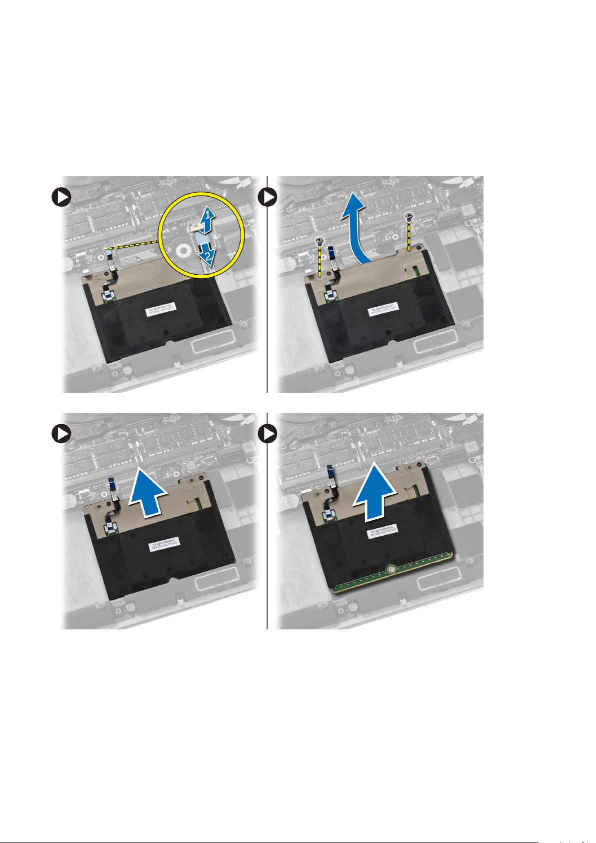
Removing the Touchpad
1. Follow the procedures in Before Working Inside Your Computer.
2. Remove the:
a) base cover
b) battery
3. Lift up the latch [1] and disconnect [2] the touchpad cable from the system board. Remove the screws that secure the touchpad to
the computer.
4. Slide out the touchpad and lift it away from the computer.
Installing the Touchpad
1. Align the touchpad in its position on the computer.
2. Tighten the screws to secure the touchpad to the computer.
3. Connect the touchpad cable to the system board.
4. Install the:
a) battery
b) base cover
5. Follow the procedures in After Working Inside Your Computer.
12
Demontáž a instalace součástí
Page 13
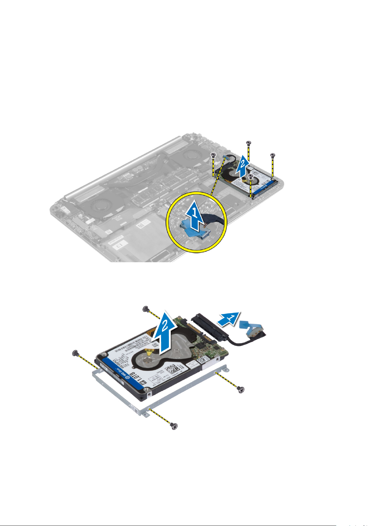
Removing the Hard Drive
1. Follow the procedures in Before Working Inside Your Computer.
2. Remove the:
a) base cover
b) battery
3. Perform the following steps to remove the hard drive from the computer:
a) Disconnect the hard-drive cable from the system board [1].
b) Remove the screws that secure the hard drive to the computer.
c) Lift the hard drive off the computer [2].
4. Perform the following steps to remove the hard-drive bracket:
a) Disconnect the hard-drive cable from the hard drive [1].
b) Remove the screws that secure the hard-drive bracket to the hard drive.
c) Lift the hard drive off the hard-drive bracket [2].
Installing the Hard Drive
1. Align the screw holes on the hard drive-bracket with the screw holes on the hard drive.
2. Tighten the screws that secure the hard-drive bracket to the hard drive.
Demontáž a instalace součástí
13
Page 14

3. Connect the hard-drive cable to the hard drive.
4. Place the hard drive on its slot on the computer.
5. Tighten the screws to secure the hard drive to the computer.
6. Connect the hard-drive cable to the system board.
7. Install the:
a) battery
b) base cover
8. Follow the procedures in After Working Inside Your Computer.
Removing the Speakers
1. Follow the procedures in Before Working Inside Your Computer.
2. Remove the:
a) base cover
b) battery
3. Perform the following steps to remove the speaker:
a) Disconnect the speaker cable from the system board [1].
b) Unroute the speaker cable and remove the cable from the routing tabs [2].
c) Remove the screw that secures the speakers to the computer.
d) Lift the speakers, along with the speaker cable, off the computer [3].
Installing the Speakers
1. Align the speakers in the slot on the computer.
2. Route the speaker cable through the routing tabs on the computer.
3. Tighten the screw to secure the speakers to the computer.
4. Connect the speaker cable to the system board.
5. Install the:
a) battery
b) base cover
6. Follow the procedures in After Working Inside Your Computer.
Removing the WLAN Card
1. Follow the procedures in Before Working Inside Your Computer.
14
Demontáž a instalace součástí
Page 15

2. Remove the:
a) base cover
b) battery
3. Perform the following steps to remove the WLAN card:
a) Remove the screw to release the bracket that secures the WLAN card to the computer. Lift the bracket away from the computer.
b) Disconnect the antenna cables from the WLAN card.
c) Slide and remove the WLAN card from its connector on the I/O board.
Installing the WLAN Card
1. Align the notch on the WLAN card with the tab on the WLAN-card connector on the I/O board.
2. Align the bracket which secures the WLAN card to the palmrest assembly.
3. Connect the antenna cables to the WLAN card.
CAUTION:
NOTE: The color of the antenna cables is visible near the tip of the cables. The antenna-cable color scheme for the
WLAN card supported by your computer is as follows:
Table 1. Antenna-Cable Color Scheme for the WLAN Card
Connectors on the WLAN card Antenna-cable color
Main (white triangle) white
Auxiliary (black triangle) black
4. Tighten the screw to secure the bracket and the WLAN card to the palmrest assembly.
5. Install the:
a) battery
b) base cover
6. Follow the procedures in After Working Inside Your Computer.
To avoid damage to the WLAN card, do not place any cables under it.
Removing the Coin-Cell Battery
1. Follow the procedures in Before Working Inside Your Computer.
CAUTION:
BIOS settings before removing the coin-cell battery.
2. Remove the:
a) base cover
b) battery
c) WLAN card
3. Perform the following steps to remove the coin-cell battery:
a) Disconnect the coin-cell battery cable from the I/O board [1].
b) Lift up and remove the coin-cell battery from the computer [2].
Removing the coin-cell battery re-sets the BIOS settings to default. It is recommended that you note the
Demontáž a instalace součástí
15
Page 16

Installing the Coin-Cell Battery
1. Replace the coin-cell battery in its slot in the computer.
2. Connect the coin-cell battery cable to the I/O board.
3. Install the:
a) WLAN card
b) battery
c) base cover
4. Follow the procedures in After Working Inside Your Computer.
Removing the mSATA Card
1. Follow the procedures in Before Working Inside Your Computer.
2. Remove the:
a) base cover
b) battery
3. Disconnect the I/O-board cable from the system board and I/O board.
4. Remove the screw that secures the mSATA card to the computer. Remove the mSATA card from the system board.
16
Demontáž a instalace součástí
Page 17

Installing the mSATA Card
1. Align the notch on the mSATA card with the tab on the mSATA-card connector.
2. Insert the mSATA card into the mSATA-card connector.
3. Tighten the screw to secure the mSATA card to the computer.
4. Connect the I/O-board cable to the system board and I/O board.
5. Install the:
a) battery
b) base cover
6. Follow the procedures in After Working Inside Your Computer.
Removing the Fans
1. Follow the procedures in Before Working Inside Your Computer.
2. Remove the:
a) base cover
b) battery
3. Perform the following steps to remove the system fan:
a) Disconnect the system fan cable from the system board [1].
b) Disconnect the camera cable from the I/O board [2].
c) Remove the screw that secures the system fan to the computer.
d) Lift the system fan away from the computer [3].
4. Perform the following steps to remove the video-card fan:
a) Disconnect the video-card fan cable from the system board [4].
b) Remove the screw that secures the video-card fan to the computer.
c) Lift the video-card fan away from the computer [5].
Demontáž a instalace součástí
17
Page 18

Installing the Fans
1. Perform the following steps to install the system fan:
a) Place the system fan in its slot in the computer.
b) Connect the system fan cable to the system board [1].
c) Connect the camera cable to the I/O board [2].
d) Tighten the screw to secure the system fan to the computer.
2. Perform the following steps to install the video-card fan:
a) Place the video-card fan in its slot in the computer.
b) Connect the video-card fan cable to the system board [4].
c) Tighten the screw to secure the video-card fan to the computer.
3. Install the:
a) battery
b) base cover
4. Follow the procedures in After Working Inside Your Computer.
Removing the Heatsink
1. Follow the procedures in Before Working Inside Your Computer.
2. Remove the:
a) base cover
b) battery
3. Remove the screws that secure the heatsink to the system board.
18
Demontáž a instalace součástí
Page 19

4. Lift the heatsink off the computer.
Installing the Heatsink
1. Align the screw holes on the heatsink with the screw holes on the system board.
2. Tighten the screws to secure the heatsink to the system board.
3. Install the:
a) battery
b) base cover
4. Follow the procedures in After Working Inside Your Computer.
Removing the Power Connector
1. Follow the procedures in Before Working Inside Your Computer.
2. Remove the:
a) base cover
b) battery
3. Disconnect the following cables from the system board:
a) power connector
Demontáž a instalace součástí
19
Page 20

b) touch panel
4. Perform the following steps to remove the power connector.
a) Release the power connector cable from under the display hinge [1].
b) Remove the screw that secures the power connector to the palmrest assembly.
c) Lift the power connector off the palmrest assembly [2].
Installing the Power Connector
1. Tighten the screw to secure the power connector to the palmrest assembly.
2. Route the power connector cable under the display hinge.
3. Connect the following cables to the system board:
a) touch panel
b) power connector
4. Install the:
a) battery
b) base cover
5. Follow the procedures in After Working Inside Your Computer.
Removing the Input/Output (I/O) Board
1. Follow the procedures in Before Working Inside Your Computer.
2. Remove the:
a) base cover
b) battery
c) WLAN card
d) coin-cell battery
3. Perform the following steps to remove the I/O board:
a) Disconnect the I/O board cable from the system board and the I/O board.
b) Disconnect the camera, fan, and coin-cell battery cables from the I/O board.
c) Remove the screws that secure the I/O board to the computer.
d) Lift the I/O board from the computer.
20
Demontáž a instalace součástí
Page 21

Installing the I/O Board
1. Tighten the screws to secure the I/O board to the computer.
2. Connect the following cables to the I/O board:
a) camera
b) fan
c) coin-cell battery
3. Connect the I/O board cable to the I/O board and the system board.
4. Install the:
a) coin-cell battery
b) WLAN card
c) battery
d) base cover
5. Follow the procedures in After Working Inside Your Computer.
Removing the System Board
1. Follow the procedures in Before Working Inside Your Computer.
2. Remove the:
a) base cover
b) battery
c) fans
d) heatsink
e) mSATA card
f) memory module(s)
NOTE:
BIOS after you replace the system board.
Your computer’s Service Tag is located under the system badge flap. You must enter the Service Tag in the
NOTE: Before disconnecting the cables from the system board, note the location of the connectors so that you can
re-connect them correctly after you replace the system board.
3. Disconnect the following cables from the system board:
a) power connector
b) touch panel
c) hard drive
d) display
Demontáž a instalace součástí
21
Page 22

4. Lift the connector latches [1] to disconnect [2] the following cables from the system board:
a) keyboard backlight
b) touchpad
c) keyboard (after peeling off the tape and lifting the connector latch)
d) speaker
5. Perform the following steps to remove the system board from the computer:
a) Loosen the captive screws that secure the system board to the computer.
b) Remove the screws that secure the system board to the computer.
c) Lift the system board off the computer.
22
Demontáž a instalace součástí
Page 23

Installing the System Board
1. Align the system board on the computer.
2. Tighten the screws and the captive screws to secure the system board to the computer.
3. Slide the keyboard cable in the connector and press down on the connector latch to secure the cable.
4. Adhere the tape to the keyboard-cable connector.
5. Route the following cables on the system board and press down on the connector latches to secure the cables:
a) speaker
b) keyboard (affix the tape)
c) touchpad
d) keyboard backlight
6. Connect the following cables to the system board:
a) display
b) hard drive
c) touch panel
d) power connector
CAUTION:
7. Install the:
a) memory module(s)
b) mSATA card
c) heatsink
d) fans
e) battery
f) base cover
8. Follow the procedures in After Working Inside Your Computer.
Make sure that no cables are placed under the system board.
Removing the Keyboard
1. Follow the procedures in Before Working Inside Your Computer.
2. Remove the:
a) base cover
b) battery
c) fans
d) heatsink
e) mSATA card
Demontáž a instalace součástí
23
Page 24

f) memory module(s)
g) system board
h) hard drive
3. Peel off the Mylar tape from the keyboard [1].
4. Remove the screws that secure the keyboard to the computer.
5. Lift and remove the keyboard from the computer.
24
Demontáž a instalace součástí
Page 25

Installing the Keyboard
1. Tighten the screws to secure the keyboard to the computer.
2. Affix the Mylar sheath to the screws on the keyboard.
3. Affix the Mylar tape to the keyboard.
4. Install the:
a) hard drive
b) system board
c) memory module(s)
d) mSATA card
e) heatsink
f) fans
g) battery
h) base cover
5. Follow the procedures in After Working Inside Your Computer.
Removing the Display Assembly
1. Follow the procedures in Before Working Inside Your Computer.
2. Remove the:
a) base cover
b) battery
3. Disconnect and remove the following cables:
a) antenna cables from the WLAN card [1]
b) camera cable from the I/O board [2]
c) touch panel [4] and display cables [3] from the system board
Demontáž a instalace součástí
25
Page 26

4. Remove the screws that secure the display hinges to the palmrest assembly.
5. Lift and remove the palmrest assembly from the display assembly.
CAUTION:
26 Demontáž a instalace součástí
Lift the palmrest assembly slowly to avoid damaging the display assembly.
Page 27

6. Slide the palmrest assembly to release the display assembly.
Installing the Display Assembly
1. Align the palmrest assembly on the display assembly.
2. Tighten the screws to secure the display hinges to the palmrest assembly.
3. Route the touch panel, display, and camera cables through the routing tabs.
4. Connect the following cables:
a) touch panel [4], and display cables [3] to the system board
b) camera cable to I/O board [2]
c) antenna cables to the WLAN card [1]
5. Install the:
a) battery
b) base cover
6. Follow the procedures in After Working Inside Your Computer.
Removing the Palmrest Assembly
1. Follow the procedures in Before Working Inside Your Computer.
Demontáž a instalace součástí
27
Page 28

2. Remove the:
a) base cover
b) battery
c) hard drive
d) speakers
e) WLAN card
f) coin-cell battery
g) mSATA card
h) fans
i) heatsink
j) power connector
k) I/O board
l) memory module(s)
m) system board
n) keyboard
3. Remove the screws that secure the display hinges to the palmrest assembly.
4. Lift the palmrest assembly away from the display assembly.
CAUTION:
5. Remove the palmrest assembly away from the display assembly.
Lift the palmrest assembly slowly to avoid damaging the display assembly.
28
Demontáž a instalace součástí
Page 29

Installing the Palmrest Assembly
1. Align the palmrest assembly on the display assembly.
2. Tighten the screws to secure the display hinges to the palmrest assembly.
3. Press down on the palmrest assembly to close the display.
4. Install the:
a) keyboard
b) system board
c) memory module(s)
d) I/O board
e) power connector
f) heatsink
g) fans
h) mSATA card
i) coin-cell battery
j) WLAN card
k) speakers
l) hard drive
m) battery
n) base cover
5. Follow the procedures in After Working Inside Your Computer.
Demontáž a instalace součástí
29
Page 30

Nastavení systému
Konfigurace systému umožňuje spravovat hardware tabletustolního počítačenotebooku a stanovit možnosti úrovně systému BIOS. V
nastavení konfigurace systému můžete:
• Měnit nastavení NVRAM po přidání nebo odebrání hardwaru
• Prohlížet konfiguraci hardwaru počítače
• Povolit nebo zakázat integrovaná zařízení
• Měnit mezní limity výkonu a napájení
• Spravovat zabezpečení počítače
Témata:
• Boot Sequence
• Navigační klávesy
• System Setup Options
• Aktualizace systému BIOS v systému Windows
• Systémové heslo a heslo pro nastavení
Boot Sequence
3
Funkce Boot Sequence nabízí rychlý a pohodlný způsob, jak obejít pořadí spouštění definované v konfiguraci systému a spustit systém
přímo z určitého zařízení (např. optická jednotka nebo pevný disk). Během testu POST (Power-on Self Test), jakmile se zobrazí logo Dell,
můžete:
• Otevřete nabídku System Setup (Konfigurace systému) stisknutím klávesy F2.
• Otevřete jednorázovou nabídku zavádění systému stisknutím klávesy F12.
Jednorázová nabídka zavádění systému obsahuje zařízení, ze kterých můžete spustit počítač, a možnost diagnostiky. Možnosti nabídky
zavádění jsou následující:
• Removable Drive (Vyjímatelný disk) (je-li k dispozici)
• STXXXX Drive (Jednotka STXXXX)
POZNÁMKA
• Optical Drive (Optická jednotka) (je-li k dispozici)
• Diagnostika
POZNÁMKA
ePSA).
Na obrazovce s pořadím zavádění jsou k dispozici také možnosti přístupu na obrazovku nástroje Konfigurace systému.
XXX představuje číslo jednotky SATA.
Po výběru možnosti Diagnostics (Diagnostika) se zobrazí obrazovka ePSA diagnostics (Diagnostika
Navigační klávesy
POZNÁMKA
restartu počítače.
Klávesy Navigace
V případě většiny možností nastavení systému se provedené změny zaznamenají, ale použijí se až po
Šipka nahoru Přechod na předchozí pole.
Šipka dolů Přechod na další pole.
Enter Výběr hodnoty ve vybraném poli (je-li to možné) nebo přechod na odkaz v poli.
Mezerník Rozbalení a sbalení rozevírací nabídky (je-li to možné).
Tab Přechod na další specifickou oblast.
30 Nastavení systému
Page 31

Klávesy Navigace
POZNÁMKA Pouze u standardního grafického prohlížeče.
Esc Přechod na předchozí stránku, dokud se nezobrazí hlavní obrazovka. Stisknutí klávesy Esc na hlavní obrazovce
zobrazí zprávu s požadavkem o uložení veškerých neuložených změn a restartuje systém.
System Setup Options
NOTE: Depending on your computer and its installed devices, the items listed in this section may or may not appear.
Table 2. Main
Option Description
System Time/Date Allows you to set the date and time.
BIOS Version Displays the BIOS version.
Product Name Displays the product name.
Dell Precision M3800 (Default Setting)
Service Tag Displays the service tag.
Asset Tag Displays the asset tag.
None (Default Setting)
CPU Type Displays the CPU type.
CPU Speed Displays the CPU speed.
CPU ID Displays the CPU ID.
CPU Cache Displays the sizes of the CPU caches.
Fixed HDD Displays the type and size of the HDD.
WDC WD10SPCX-75HWSTO (1000 GB) (Default Setting)
mSATA Device Displays the type and size of the mSATA device.
AC Adapter Type Displays the type of the AC adapter.
None (Default Setting)
System Memory Displays the size of the system memory.
Extended Memory Displays the size of the extended memory.
Memory Speed Displays the speed of the memory.
Keyboard Type Displays the type of keyboard.
Backlite (Default Setting)
Table 3. Advanced
Option Description
Intel (R) SpeedStep (TM) Allows you to enable or disable the Intel (R) SpeedStep (TM) feature.
Enabled (Default Setting)
Virtualization This option specifies whether a Virtual Machine Monitor (VMM) can utilize the additional hardware
capabilities provided by Intel Virtualization technology. Allows you to enable or disable the
Virtualization feature.
Enabled (Default Setting)
USB Emulation Allows you to enable or disable the USB Emulation feature.
Nastavení systému 31
Page 32

Option Description
Enabled (Default Setting)
USB PowerShare Allows you to enable or disable the USB PowerShare feature.
Enabled (Default Setting)
USB Wake Support This option allows you to enable USB devices to wake the system from Standby.
Disable(Default Setting)
SATA Operation Displays the SATA Operation information.
Adapter Warnings Allows you to enable or disable the adapter warnings feature.
Multimedia Key Behaviour
Battery Health Displays the battery health information.
Battery Charge Configuration
Miscellaneous Devices Allows you enable or disable the various on board devices. The options are:
Table 4. Security
Option Description
Unlock Setup Status
Function Key (Default Setting)
Adaptive (Default Setting)
• External USB Ports - Enabled (Default Setting)
• USB Debug - Disabled (Default Setting)
Unlocked (Default Setting)
Admin Password Status Displays the status of the admin password.
Default Setting: Not set
System Password Status Displays the status of the system password.
Default Setting: Not set
HDD Password Status Displays the status of the system password.
Default Setting: Not set
Asset Tag Allows you to set the asset tag.
Admin Password Allows you to set, change, or delete the administrator (admin) password.
NOTE: You must set the admin password before you set the system or hard drive
password.
NOTE: Successful password changes take effect immediately.
NOTE: Deleting the admin password automatically deletes the system password
and the hard drive password.
NOTE: Successful password changes take effect immediately.
System Password Allows you to set, change or delete the system password.
NOTE: Successful password changes take effect immediately.
HDD Password Allows you to set, change or delete the administrator password.
Password Change Allows you to enable or disable permissions to set a System password and a Hard Drive
password when the admin password is set.
Default Setting: Permitted
Computrace Allows you to activate or disable the optional Computrace software The options are:
• Deactivate (Default Setting)
• Activate
32 Nastavení systému
Page 33

Option Description
NOTE: The Activate and Disable options will permanently activate or disable the
feature and no further changes will be allowed.
TPM Security This option lets you control whether the Trusted Platform Module (TPM) in the system is
enabled and visible to the operating system. When disabled the BIOS will not turn On the TPM
During POST. The TPM will be non-functional and invisible to the operating system. When
enabled, the BIOS will turn On the TPM during POST so that it can be used by the operating
system. This option is
NOTE: Disabling this option does not change any settings you may have made to
the TPM, nor does it delete or change any information or keys you may have
stored there. It simply turns Off the TPM so that it cannot be used. When you reenable this option, the TPM will function exactly as it did before it was disabled.
NOTE: Changes to this option take effect immediately.
Table 5. Boot
Option Description
Boot List Option
Secure Boot This option enables or disables the Secure Boot feature.
Default Setting: Legacy
• Disabled (Default Setting) - Windows 7
• Enabled - Windows 8.1
Enable by default.
Load Legacy Option ROM This option enables or disables the Load Legacy Option ROM feature.
• Enabled (Default Setting) - Windows 7
• Disabled - Windows 8.1
Set Boot Priority Allows you to change the order in which the computer attempts to find an operating system:
• 1 st Boot Priority [ CD/DVD/CD-RW Drive]
• 2nd Boot Priority [Network]
• 3rd Boot Priority [mini SSD]
• 4th Boot Priority [USB Storage Device
• 5th Boot Priority [Hard Drive]
• 6th Boot Priority [Diskette Drive]
Table 6. Exit
Option Description
Save Changes and Reset Allows you to save the changes you made.
Discard Changes and Reset Allows you to discard the changes you made.
Restore Defaults Allows you to restore the default options.
Discard Changes Allows you to discard the changes you made.
Save Changes Allows you to save the changes you made.
Aktualizace systému BIOS v systému Windows
Systém BIOS (nastavení systému) se doporučuje aktualizovat tehdy, když měníte základní desku nebo je k dispozici aktualizace. V případě
notebooků zajistěte, aby baterie byla plně nabitá a notebook byl připojen do elektrické sítě.
POZNÁMKA
dokončení aktualizace systému BIOS.
1. Restartujte počítač.
2. Přejděte na web Dell.com/support.
Je-li zapnutá technologie BitLocker, je třeba ji před aktualizací systému BIOS vypnout a zapnout až po
Nastavení systému
33
Page 34

• Zadejte servisní označení nebo kód expresní služby a klepněte na tlačítko Submit (Odeslat).
• Klikněte na možnost Rozpoznat produkt a postupujte podle instrukcí na obrazovce.
3. Pokud nemůžete nelézt výrobní číslo, klepněte na Vybrat ze všech produktů.
4. Vyberte kategorii Products (Produkty) ze seznamu.
POZNÁMKA Zvolte vhodnou kategorii, skrze niž se dostanete na stránku produktu.
5. Vyberte model svého počítače. Zobrazí se stránka produktové podpory pro váš počítač.
6. Klikněte na možnost Get drivers (Získat ovladače) a poté na možnost Drivers and Downloads (Ovladače a stahování).
Zobrazí se stránka ovladačů a souborů ke stažení.
7. Klikněte na Find it myself (Vyhledám verzi sám).
8. Kliknutím na BIOS se zobrazí verze systému BIOS.
9. Vyhledejte nejnovější soubor se systémem BIOS a klikněte na tlačítko Download (Stáhnout).
10. V okně Please select your download method below (Zvolte metodu stažení) klikněte na tlačítko Download File (Stáhnout
soubor).
Zobrazí se okno File Download (Stažení souboru).
11. Klepnutím na tlačítko Save (Uložit) uložíte soubor do počítače.
12. Klepnutím na tlačítko Run (Spustit) v počítači nainstalujete aktualizované nastavení systému BIOS.
Postupujte podle pokynů na obrazovce.
POZNÁMKA Doporučuje se neaktualizovat verze systému BIOS na více než 3 revize. Například: Pokud chcete
aktualizovat systém BIOS z verze 1.0 na verzi 7.0, nainstalujte nejprve verzi 4.0 a poté nainstalujte verzi 7.0.
Systémové heslo a heslo pro nastavení
Můžete vytvořit systémové heslo a zabezpečit počítač heslem.
Typ hesla
Heslo systému Heslo, které je třeba zadat před přihlášením se k počítači.
Heslo nastavení Heslo, které je třeba zadat před získáním přístupu a možností provádění změn v nastavení systému BIOS v
VÝSTRAHA Heslo nabízí základní úroveň zabezpečení dat v počítači.
VÝSTRAHA Pokud počítač nebude uzamčen nebo zůstane bez dozoru, k uloženým datům může získat přístup kdokoli.
POZNÁMKA Počítač, který vám zašleme, má funkci hesla systému a hesla nastavení vypnutou.
Popis
počítači.
Nastavení systémového hesla a hesla pro nastavení
Nové System Password (Systémové heslo) pouze v případě, že je status Not Set (Nenastaveno).
Do nastavení systému přejdete stisknutím tlačítka F2 ihned po spuštění či restartu počítače.
1. Na obrazovce System BIOS (Systém BIOS) nebo System Setup (Nastavení systému) vyberte možnost Security
(Zabezpečení) a stiskněte klávesu Enter.
Otevře se obrazovka Security (Zabezpečení).
2. Zvolte System Password (Systémové heslo) a v poli Enter the new password (Zadejte nové heslo) vyvořte heslo.
Nové heslo systému přiřaďte podle následujících pokynů:
• Heslo smí obsahovat nejvýše 32 znaků.
• Heslo smí obsahovat čísla od 0 do 9.
• Povolena jsou pouze malá písmena (velká písmena jsou zakázána).
• Povoleny jsou pouze následující zvláštní znaky: mezera, (”), (+), (,), (-), (.), (/), (;), ([), (\), (]), (`).
3. Vypište systémové heslo, které jste zadali dříve do pole Confirm new password (Potvrdit nové heslo) a klikněte na OK.
4. Po stisku klávesy Esc se zobrazí zpráva s požadavkem o uložení změn.
5. Stiskem klávesy Y změny uložíte.
Počítač se restartuje.
34
Nastavení systému
Page 35

Odstranění nebo změna stávajícího hesla k systému nebo nastavení
Před pokusem o odstranění nebo změnu stávajícího hesla k systému a/nebo konfiguraci ověřte, zda je možnost Password Status (Stav
hesla) v programu System Setup (Konfigurace systému) nastavena na hodnotu Unlocked (Odemčeno). Pokud je možnost Password
Status (Stav hesla) nastavena na hodnotu Locked (Zamčeno), stávající heslo k systému a/nebo konfiguraci nelze odstranit ani změnit.
Nástroj Nastavení systému otevřete stiskem tlačítka F2 ihned po spuštění či restartu počítače.
1. Na obrazovce System BIOS (Systém BIOS) nebo System Setup (Nastavení systému) vyberte možnost System Security
(Zabezpečení systému) a stiskněte klávesu Enter.
Otevře se obrazovka System Security (Zabezpečení systému).
2. Na obrazovce System Security (Zabezpečení systému) ověřte, zda je v nastavení Password Status (Stav hesla) vybrána
možnost Unlocked (Odemčeno).
3. Po odstranění stávajícího hesla systému vyberte možnost System Password (Heslo systému) a stiskněte klávesu Enter nebo Tab.
4. Po odstranění stávajícího hesla nastavení vyberte možnost Setup Password (Heslo nastavení) a stiskněte klávesu Enter nebo Tab.
POZNÁMKA Po změně hesla systému nebo nastavení zadejte po zobrazení výzvy nové heslo. Jestliže heslo systému
nebo nastavení odstraníte, potvrďte po zobrazení výzvy své rozhodnutí.
5. Po stisku klávesy Esc se zobrazí zpráva s požadavkem o uložení změn.
6. Stiskem klávesy Y uložíte změny a nástroj Nastavení systému ukončíte.
Počítač se restartuje.
Nastavení systému 35
Page 36

4
Diagnostika
Vyskytnou-li se potíže s počítačem, spusťte před kontaktováním společnosti Dell a vyhledáním technické podpory diagnostiku ePSA. Cílem
diagnostiky je vyzkoušet hardware počítače bez nutnosti použít dodatečné zařízení nebo rizika ztráty dat. Pokud nedokážete problém sami
napravit, výsledky diagnostiky mohou zaměstnancům podpory pomoci ve vyřešení problému za vás.
Témata:
• Rozšířená diagnostika vyhodnocení systému před jeho spuštěním (ePSA)
• Device Status Light
Rozšířená diagnostika vyhodnocení systému před jeho spuštěním (ePSA)
Diagnostika ePSA (známá také jako diagnostika systému) provádí celkovou kontrolu hardwaru. Diagnostika ePSA je integrována do
systému BIOS a je spouštěna interně systémem BIOS. Vestavěná diagnostika systému poskytuje sadu možností pro konkrétní zařízení
nebo jejich skupiny a umožní vám:
• Spouštět testy automaticky nebo v interaktivním režimu
• Opakovat testy
• Zobrazit nebo ukládat výsledky testů
• Procházet testy a využitím dalších možností testu získat dodatečné informace o zařízeních, u kterých test selhal
• Prohlížet stavové zprávy s informacemi o úspěšném dokončení testu
• Prohlížet chybové zprávy s informacemi o problémech, ke kterým během testu došlo
VÝSTRAHA
může mít za následek neplatné výsledky nebo chybové zprávy.
POZNÁMKA Některé testy pro konkrétní zařízení vyžadují zásah uživatele. Při provádění diagnostických testů buďte
vždy přítomni u terminálu počítače.
Používejte diagnostiku systému pouze k testování tohoto počítače. Použití tohoto programu s jinými počítači
Device Status Light
Icon
Description
Turns on when you turn on the computer.
36 Diagnostika
Page 37

Technical Specifications
NOTE: Offerings may vary by region. For more information regarding the configuration of your computer, click Start
(Start icon) > Help and Support, and then select the option to view information about your computer.
Table 7. System Information
Feature Specification
System Chipset Mobile Intel 8 Series Chipset
DMA Channels two VT-d DMA remap engines
Interrupt Levels Intel 64 and IA-32 Architecture
BIOS Chip (NVRAM) 8 MB
Table 8. Processor
Feature Specification
Processor type Intel Core i7 Quad Core
L1 cache up to 256 KB cache depending on processor type
L2 cache up to 1024 KB cache depending on processor type
L3 cache up to 6144 KB cache depending on processor type
5
Table 9. Memory
Feature Specification
Type DDR3L
Speed 1600 MHz
Connectors 2 SoDIMM Sockets
Capacity 8 GB, 12 GB, and 16 GB
Minimum Memory 8 GB
Maximum memory 16 GB
Table 10. Video
Feature Specification
Type discrete
Data bus PCIE x16, Gen3
Video controller and memory: NVIDIA Quadro K1100M , 2 GB GDDR5(4 Pcs 128Mx32), 1.5 V based
Table 11. Audio
Feature Specification
Integrated dual-channel High-Definition audio
Table 12. Communication
Feature Specification
Network adapter ethernet via USB-to-Ethernet Dongle provided in box.
Technical Specifications 37
Page 38

Feature Specification
NOTE: No RJ45 (10/100/1000Base-T, IPv6) provided.
Wireless wireless On/Off implemented via keyboard wireless key
• WLAN and Bluetooth BT 4.0 + LE combo card support
• Bluetooth 2.1/3.0/4.0/4.1 with Wi-Fi combo module
Table 13. Ports and Connectors
Feature Specification
Audio
USB 2.0 one
USB 3.0 three
Video
Memory card reader SD 4.0
Table 14. Display
Feature Specification
Type 1366 X 768 pixels
Size 15.6 inches
Dimensions:
Height 254.0 mm (9.99 inches)
Width 372.0 mm (14.64 inches)
Diagonal 396.24 mm (15.60 inches)
Active area (X/Y) 344.16 mm X 193.59 mm / 345.60 mm X 194.40 mm (13.5 inches X 7.62 inches /
Maximum resolution 1920 X 1080 pixels / 3200 X 1800 pixels
Maximum Brightness 400 nits
Operating angle 0° (closed) to 135°
Refresh rate 60 Hz
Minimum viewing angles:
Horizontal 80/80
Vertical 80/80
• Microphone/Headphone Universal Audio jack support
• Autosense Headphone/Microphone combo jack support (1/8 inches
connector)
• Mini-DisplayPort DP 1.2 support
• HDMI 1.4a with audio; Intel Media Vault support through HDMI port
13.60 inches X 7.65 inches)
Table 15. Keyboard
Feature Specification
Number of keys
Layout QWERTY/AZERTY/Kanji
38 Technical Specifications
• United States: 80 keys
• United Kingdom: 81 keys
• Brazil: 81 keys
• Japan: 84 keys
Page 39

Table 16. Touchpad
Feature Specification
Active Area:
X-axis 105 mm
Y-axis 80 mm
Table 17. Camera
Feature Specification
Type HD Camera / Digital Array Microphone
Still Resolution 0.92 megapixels (Maximum)
Video Resolution 1280 x 720 pixels at 30 frames per second (Maximum)
Diagonal 74 degrees
Table 18. Storage
Feature Specification
Storage:
Storage Interface SATA 3 (6 Gb/s)
Drives configurations:
Hard Drives (optional) one internal 2.5 inch SATA HDD
Solid State Drives (optional) one Solid State Drive (SSD), Full Mini Card (FMC)
Size: 128 GB, 256 GB, 500 GB, 512 GB, and 1 TB
Table 19. Battery
Feature Specification
Type Li-polymer 6-cell (61 Wh) / 6-cell (91 Wh)
Dimensions :
61 Wh :
Depth 92.65 mm (3.64 inches)
Height 9 mm (0.35 inches)
Width 270 mm (10.62 inches)
Weight 320 g (0.70 lb)
91 Wh :
Depth 92.65 mm (3.64 inches)
Height 9 mm (0.35 inches)
Width 342.45 mm (13.48 inches)
Weight 443 g (0.97 lb)
Voltage 11.1 V
Life span 300 discharge/charge cycles
Temperature range:
Operating (approximate)
• Charge : 0 °C to 50 °C (32 °F to 158 °F)
• Discharge: 0 °C to 70 °C (32 °F to 122 °F)
• Operating: 0 °C to 35 °C (32 °F to 95 °F)
Non-operating –40 °C to 65 °C (–40 °F to 149 °F)
Technical Specifications 39
Page 40

Feature Specification
Coin-cell battery 3 V CR2032 lithium-ion cell
Table 20. AC Adapter
Feature Specification
Input voltage 100 VAC to 240 VAC
Input current (maximum) 1.80 A
Input frequency 50 Hz to 60 Hz
Output power 130 W
Output current 6.67 A
Rated output voltage 19.50 VDC
Dimensions:
Height 22 mm (0.86 inches)
Width 66 mm (2.59 inches)
Depth 143 mm (5.62 inches)
Temperature range:
Operating 0 °C to 40 °C (32 °F to 104 °F)
Non Operating –40 °C to 70 °C (–40 °F to 158 °F)
Table 21. Physical Dimensions
Physical Specification
Height: 18 mm to 18.37 mm max (0.70 inches to 0.72 inches)
Width 372.2 mm (14.60 inches)
Depth 253.9 mm (9.99 inches)
Weight (Minimum) 1.31 kg (4.5 lb)
Table 22. Environmental
Feature Specification
Temperature range:
Operating 0 °C to 40 °C (32 °F to 104°F)
Storage –40 °C to 70 °C (–40 °F to 158 °F)
Relative humidity (maximum):
Operating 10 % to 90 % (non-condensing)
Storage 10 % to 95 % (non-condensing)
Maximum vibration:
Operating 0.66 GRMS, 2 Hz - 600 Hz
Storage 1.3 GRMS, 2 Hz - 600 Hz
Maximum shock:
Operating 110 G, 2 ms
Non-operating 160 G, 2 ms
Altitude:
Operating
–15.2 m to 30482000 m (–50 to 10,0006560 ft)
Storage 15.2 m to 10,668 m (–50 ft to 35,000 ft)
40 Technical Specifications
Page 41

Feature Specification
Airborne contaminant level G1 as defined by ISA-S71.04-1985
Technical Specifications 41
Page 42

6
Kontaktování společnosti Dell
POZNÁMKA Pokud nemáte aktivní internetové připojení, můžete najít kontaktní informace na nákupní faktuře, balicím
seznamu, účtence nebo v katalogu produktů společnosti Dell.
Společnost Dell nabízí několik možností online a telefonické podpory a služeb. Jejich dostupnost závisí na zemi a produktu a některé služby
nemusí být ve vaší oblasti k dispozici. Chcete-li kontaktovat společnost Dell se záležitostmi týkajícími se prodejů, technické podpory nebo
zákaznického servisu:
1. Přejděte na web Dell.com/support.
2. Vyberte si kategorii podpory.
3. Ověřte svou zemi nebo region v rozbalovací nabídce Choose a Country/Region (Vyberte zemi/region) ve spodní části stránky.
4. Podle potřeby vyberte příslušné servisní služby nebo linku podpory.
42 Kontaktování společnosti Dell
 Loading...