

Page 1
®
'HOO,QVSLURQ6HULHV
6(59,&(0$18$/
ZZZGHOOFRP
Page 2

____________________
Information in this manual is subject to change without notice.
1997-1998 Dell Computer Corporation. All rights reserved.
Reproduction in any manner whatsoever without the written permission of Del l Computer Corporation is strictly forbidden.
Trademarks used in this text: Dell and the DELL logo are registered trademarks and Inspiron is a trademark of Dell Computer Corporation; MS-DOS is a registered
trademark of Microsoft Corporation; Intel and Pentium are registered trademarks and MMX is a trademark of Intel Corporation ; IB M is a registered trademark of
International Busin ess Ma chines Corporation.
Other trademarks and tr ade names may be used in this document to refer to either the ent it ie s cl ai m ing the marks and names or their products. Dell Computer
Corporation disclai m s any pr oprietary interest in trademarks and trade name s other than its own.
July 1998 P/N 55900 Rev. A03
Page 3

Contents
Chapter 1
System Overview. . . . . . . . . . . . . . . . . . . . . . . . . . . . . . . 1-1
System Features . . . . . . . . . . . . . . . . . . . . . . . . . . . . . . . . . . . . . . . . . . . . . . . 1-1
Physical Description . . . . . . . . . . . . . . . . . . . . . . . . . . . . . . . . . . . . . . . . . . . . 1-3
Status Display . . . . . . . . . . . . . . . . . . . . . . . . . . . . . . . . . . . . . . . . . . . . . . 1-4
Keyboard Indicators . . . . . . . . . . . . . . . . . . . . . . . . . . . . . . . . . . . . . . 1-4
CD-ROM/DVD-ROM/Hard-Disk Drive Indicator. . . . . . . . . . . . . . . 1-4
Diskette-Drive Access Indicator. . . . . . . . . . . . . . . . . . . . . . . . . . . . . 1-5
PC Card Indicator . . . . . . . . . . . . . . . . . . . . . . . . . . . . . . . . . . . . . . . . 1-5
AC Power Indicator . . . . . . . . . . . . . . . . . . . . . . . . . . . . . . . . . . . . . . 1-5
Battery Activity Indicator . . . . . . . . . . . . . . . . . . . . . . . . . . . . . . . . . 1-5
Battery Status Indicator . . . . . . . . . . . . . . . . . . . . . . . . . . . . . . . . . . . 1-5
Battery Charge Gauge . . . . . . . . . . . . . . . . . . . . . . . . . . . . . . . . . . . . . . . 1-6
System Power . . . . . . . . . . . . . . . . . . . . . . . . . . . . . . . . . . . . . . . . . . . . . . . . . 1-7
Power Conservation . . . . . . . . . . . . . . . . . . . . . . . . . . . . . . . . . . . . . . . 1-7
Interrupt Assignments. . . . . . . . . . . . . . . . . . . . . . . . . . . . . . . . . . . . . . . . . . . 1-8
Technical Specifications. . . . . . . . . . . . . . . . . . . . . . . . . . . . . . . . . . . . . . . . . 1-9
Chapter 2
Initial Procedures . . . . . . . . . . . . . . . . . . . . . . . . . . . . . . 2-1
Initial User Contact . . . . . . . . . . . . . . . . . . . . . . . . . . . . . . . . . . . . . . . . . . . 2-1
Visual Inspection . . . . . . . . . . . . . . . . . . . . . . . . . . . . . . . . . . . . . . . . . . . . . 2-1
Observing the Boot Routine . . . . . . . . . . . . . . . . . . . . . . . . . . . . . . . . . . . . . . 2-3
Eliminating Resource Conflicts . . . . . . . . . . . . . . . . . . . . . . . . . . . . . . . . . . 2-4
Getting Help . . . . . . . . . . . . . . . . . . . . . . . . . . . . . . . . . . . . . . . . . . . . . . . . . 2-5
v
Page 4

Chapter 3
Beep Codes and Error Messages . . . . . . . . . . . . . . . . . . 3-1
POST Beep Codes . . . . . . . . . . . . . . . . . . . . . . . . . . . . . . . . . . . . . . . . . . 3-1
System Error Messages . . . . . . . . . . . . . . . . . . . . . . . . . . . . . . . . . . . . . . . . . 3-2
Running the Dell Diagnostics . . . . . . . . . . . . . . . . . . . . . . . . . . . . . . . . . . 3-4
Chapter 4
Removing and Replacing Parts . . . . . . . . . . . . . . . . . . . 4-1
Recommended Tools . . . . . . . . . . . . . . . . . . . . . . . . . . . . . . . . . . . . . . . . . . . 4-1
Screw Identification and Tightening . . . . . . . . . . . . . . . . . . . . . . . . . . . . . . . 4-2
Precautionary Measures . . . . . . . . . . . . . . . . . . . . . . . . . . . . . . . . . . . . . . . . . 4-3
ZIF Connectors. . . . . . . . . . . . . . . . . . . . . . . . . . . . . . . . . . . . . . . . . . . . . . . . 4-9
Exploded Views of Components and Assemblies . . . . . . . . . . . . . . . . . . . . 4-10
Factory Repair Parts and Assemblies. . . . . . . . . . . . . . . . . . . . . . . . . . . . . . 4-15
Hard-Disk Drive. . . . . . . . . . . . . . . . . . . . . . . . . . . . . . . . . . . . . . . . . . . . . . 4-29
Diskette Drive. . . . . . . . . . . . . . . . . . . . . . . . . . . . . . . . . . . . . . . . . . . . . . . . 4-30
CD-ROM/DVD-ROM Drive . . . . . . . . . . . . . . . . . . . . . . . . . . . . . . . . . . . . 4-31
General Disassembly . . . . . . . . . . . . . . . . . . . . . . . . . . . . . . . . . . . . . . . . . . 4-32
Preparation . . . . . . . . . . . . . . . . . . . . . . . . . . . . . . . . . . . . . . . . . . . . . . . 4-32
Keyboard . . . . . . . . . . . . . . . . . . . . . . . . . . . . . . . . . . . . . . . . . . . . . . . . . . . 4-33
Heat Sink . . . . . . . . . . . . . . . . . . . . . . . . . . . . . . . . . . . . . . . . . . . . . . . . . . . 4-35
Status Display Panel. . . . . . . . . . . . . . . . . . . . . . . . . . . . . . . . . . . . . . . . . . . 4-36
LCD Assembly. . . . . . . . . . . . . . . . . . . . . . . . . . . . . . . . . . . . . . . . . . . . . . . 4-37
Palmrest Assembly. . . . . . . . . . . . . . . . . . . . . . . . . . . . . . . . . . . . . . . . . . . . 4-39
IR Board. . . . . . . . . . . . . . . . . . . . . . . . . . . . . . . . . . . . . . . . . . . . . . . . . 4-41
Hard-Disk Drive Heat Sink . . . . . . . . . . . . . . . . . . . . . . . . . . . . . . . . . . 4-42
Touch-Pad Assembly . . . . . . . . . . . . . . . . . . . . . . . . . . . . . . . . . . . . . . . 4-43
Speakers . . . . . . . . . . . . . . . . . . . . . . . . . . . . . . . . . . . . . . . . . . . . . . . . . 4-44
Base Assembly. . . . . . . . . . . . . . . . . . . . . . . . . . . . . . . . . . . . . . . . . . . . . . . 4-45
IR Lens. . . . . . . . . . . . . . . . . . . . . . . . . . . . . . . . . . . . . . . . . . . . . . . . . . 4-47
Processor Board . . . . . . . . . . . . . . . . . . . . . . . . . . . . . . . . . . . . . . . . . . . 4-48
LVDS Board. . . . . . . . . . . . . . . . . . . . . . . . . . . . . . . . . . . . . . . . . . . . . . 4-49
USB Board . . . . . . . . . . . . . . . . . . . . . . . . . . . . . . . . . . . . . . . . . . . . . . . 4-50
Main Board. . . . . . . . . . . . . . . . . . . . . . . . . . . . . . . . . . . . . . . . . . . . . . . 4-51
Audio Bezel . . . . . . . . . . . . . . . . . . . . . . . . . . . . . . . . . . . . . . . . . . . . . . 4-52
Audio Board. . . . . . . . . . . . . . . . . . . . . . . . . . . . . . . . . . . . . . . . . . . . . . 4-53
vi
Page 5

PC Card Cage . . . . . . . . . . . . . . . . . . . . . . . . . . . . . . . . . . . . . . . . . . . . . 4-54
Latch Assembly . . . . . . . . . . . . . . . . . . . . . . . . . . . . . . . . . . . . . . . . . . . 4-55
Kensington Lock Plate . . . . . . . . . . . . . . . . . . . . . . . . . . . . . . . . . . . . . . 4-56
12.1-Inch LCD Components. . . . . . . . . . . . . . . . . . . . . . . . . . . . . . . . . . . . . 4-57
12.1-Inch LCD Front Bezel . . . . . . . . . . . . . . . . . . . . . . . . . . . . . . . . . . 4-57
12.1-Inch LCD Panel . . . . . . . . . . . . . . . . . . . . . . . . . . . . . . . . . . . . . . . 4-59
12.1-Inch LCD Inverter Board . . . . . . . . . . . . . . . . . . . . . . . . . . . . . . . . 4-60
12.1-Inch LCD Hinges . . . . . . . . . . . . . . . . . . . . . . . . . . . . . . . . . . . . . . 4-61
12.1-Inch LCD Bracket. . . . . . . . . . . . . . . . . . . . . . . . . . . . . . . . . . . . . . 4-62
13.3-Inch LCD Components. . . . . . . . . . . . . . . . . . . . . . . . . . . . . . . . . . . . . 4-63
13.3-Inch LCD Front Bezel . . . . . . . . . . . . . . . . . . . . . . . . . . . . . . . . . . 4-63
13.3-Inch LCD Panel . . . . . . . . . . . . . . . . . . . . . . . . . . . . . . . . . . . . . . . 4-65
13.3-Inch LCD Inverter Board . . . . . . . . . . . . . . . . . . . . . . . . . . . . . . . . 4-67
13.3-Inch LCD Hinges . . . . . . . . . . . . . . . . . . . . . . . . . . . . . . . . . . . . . . 4-68
13.3-Inch LCD Bracket. . . . . . . . . . . . . . . . . . . . . . . . . . . . . . . . . . . . . . 4-69
Index
Figures
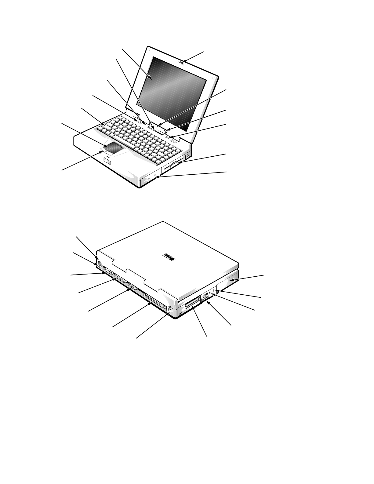
Figure 1-1. Front View of the Portable Computer . . . . . . . . . . . . . . . . . . . 1-3
Figure 1-2. Back View of the Portable Computer . . . . . . . . . . . . . . . . . . . 1-3
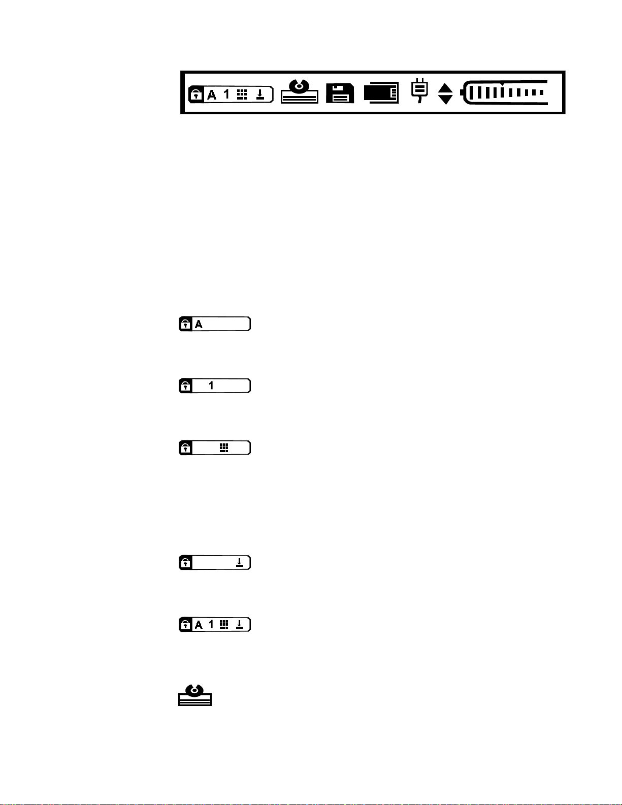
Figure 1-3. Status Display Panel. . . . . . . . . . . . . . . . . . . . . . . . . . . . . . . . . 1-4
Figure 1-4. Battery Charge Gauge . . . . . . . . . . . . . . . . . . . . . . . . . . . . . . . 1-7
Figure 4-1. Computer Orientation . . . . . . . . . . . . . . . . . . . . . . . . . . . . . . . 4-1
Figure 4-2. Screw Identification (Example) . . . . . . . . . . . . . . . . . . . . . . . . 4-2
Figure 4-3. AC Adapter Removal. . . . . . . . . . . . . . . . . . . . . . . . . . . . . . . . 4-4
Figure 4-4. Computer Removal From Replicator. . . . . . . . . . . . . . . . . . . . 4-4
Figure 4-5. Main Battery Removal. . . . . . . . . . . . . . . . . . . . . . . . . . . . . . . 4-5
Figure 4-6. PC Card Removal. . . . . . . . . . . . . . . . . . . . . . . . . . . . . . . . . . . 4-6
Figure 4-7. Hard-Disk Drive Removal . . . . . . . . . . . . . . . . . . . . . . . . . . . . 4-7
Figure 4-8. Removing a Memory Module . . . . . . . . . . . . . . . . . . . . . . . . . 4-7
Figure 4-9. Diskette Drive, Secondary Battery, CD-ROM Drive, or
DVD-ROM Drive Removal. . . . . . . . . . . . . . . . . . . . . . . . . . . 4-8
Figure 4-10. Releasing a ZIF Connector . . . . . . . . . . . . . . . . . . . . . . . . . . . 4-9
Figure 4-11. Exploded View—Computer. . . . . . . . . . . . . . . . . . . . . . . . . . 4-10
Figure 4-12. Exploded View—12.1-Inch LCD Assembly . . . . . . . . . . . . . 4-11
Figure 4-13. Exploded View—13.3-Inch LCD Assembly . . . . . . . . . . . . . 4-12
Figure 4-14. Exploded View—Palmrest Assembly . . . . . . . . . . . . . . . . . . 4-13
Figure 4-15. Exploded View—Base Assembly . . . . . . . . . . . . . . . . . . . . . 4-14
vii
Page 6

Figure 4-16. Hard-Disk Drive Disassembly. . . . . . . . . . . . . . . . . . . . . . . . 4-29
Figure 4-17. Diskette Drive Disassembly . . . . . . . . . . . . . . . . . . . . . . . . . 4-30
Figure 4-18. CD-ROM/DVD-ROM Drive Disassembly . . . . . . . . . . . . . . 4-31
Figure 4-19. Location Template. . . . . . . . . . . . . . . . . . . . . . . . . . . . . . . . . 4-32
Figure 4-20. Keyboard Removal . . . . . . . . . . . . . . . . . . . . . . . . . . . . . . . . 4-33
Figure 4-21. Heat Sink Removal . . . . . . . . . . . . . . . . . . . . . . . . . . . . . . . . 4-35
Figure 4-22. Status Display Panel Removal. . . . . . . . . . . . . . . . . . . . . . . . 4-36
Figure 4-23. LCD Assembly Removal. . . . . . . . . . . . . . . . . . . . . . . . . . . . 4-37
Figure 4-24. Palmrest Assembly Removal . . . . . . . . . . . . . . . . . . . . . . . . 4-39
Figure 4-25. IR Board Removal. . . . . . . . . . . . . . . . . . . . . . . . . . . . . . . . . 4-41
Figure 4-26. Hard-Disk Drive Heat Sink Removal . . . . . . . . . . . . . . . . . . 4-42
Figure 4-27. Touch-Pad Assembly Removal. . . . . . . . . . . . . . . . . . . . . . . 4-43
Figure 4-28. Speaker Removal. . . . . . . . . . . . . . . . . . . . . . . . . . . . . . . . . . 4-44
Figure 4-29. Base Assembly . . . . . . . . . . . . . . . . . . . . . . . . . . . . . . . . . . . 4-46
Figure 4-30. IR Lens Removal . . . . . . . . . . . . . . . . . . . . . . . . . . . . . . . . . 4-47
Figure 4-31. Processor Board Removal . . . . . . . . . . . . . . . . . . . . . . . . . . . 4-48
Figure 4-32. LVDS Board Removal . . . . . . . . . . . . . . . . . . . . . . . . . . . . . 4-49
Figure 4-33. USB Board Removal. . . . . . . . . . . . . . . . . . . . . . . . . . . . . . . 4-50
Figure 4-34. Main Board Removal . . . . . . . . . . . . . . . . . . . . . . . . . . . . . . 4-51
Figure 4-35. Audio Bezel Removal . . . . . . . . . . . . . . . . . . . . . . . . . . . . . . 4-52
Figure 4-36. Audio Board Removal . . . . . . . . . . . . . . . . . . . . . . . . . . . . . 4-53
Figure 4-37. PC Card Cage Removal . . . . . . . . . . . . . . . . . . . . . . . . . . . . 4-54
Figure 4-38. Latch Assembly Removal . . . . . . . . . . . . . . . . . . . . . . . . . . . 4-55
Figure 4-39. Kensington Lock Plate Removal . . . . . . . . . . . . . . . . . . . . . 4-56
Figure 4-40. 12.1-Inch LCD Front Bezel Removal . . . . . . . . . . . . . . . . . 4-57
Figure 4-41. 12.1-Inch LCD Panel Removal . . . . . . . . . . . . . . . . . . . . . . . 4-59
Figure 4-42. 12.1-Inch Inverter Board Removal . . . . . . . . . . . . . . . . . . . . 4-60
Figure 4-43. 12.1-Inch LCD Hinges Removal . . . . . . . . . . . . . . . . . . . . . 4-61
Figure 4-44. 12.1-Inch LCD Bracket Removal . . . . . . . . . . . . . . . . . . . . . 4-62
Figure 4-45. 13.3-Inch LCD Front Bezel Removal . . . . . . . . . . . . . . . . . 4-63
Figure 4-46. 13.3-Inch LCD Panel Removal . . . . . . . . . . . . . . . . . . . . . . 4-65
Figure 4-47. 13.3-Inch Inverter Board Removal . . . . . . . . . . . . . . . . . . . 4-67
Figure 4-48. 13.3-Inch LCD Hinges Removal . . . . . . . . . . . . . . . . . . . . . 4-68
Figure 4-49. 13.3-Inch LCD Bracket Removal . . . . . . . . . . . . . . . . . . . . . 4-69
viii
Page 7

Tables
Table 1-1. Interrupt Assignments . . . . . . . . . . . . . . . . . . . . . . . . . . . . . . . 1-8
Table 1-2. Technical Specifications . . . . . . . . . . . . . . . . . . . . . . . . . . . . . 1-9
Table 3-1. POST Beep Codes . . . . . . . . . . . . . . . . . . . . . . . . . . . . . . . . . . 3-2
Table 3-2. System Error Messages . . . . . . . . . . . . . . . . . . . . . . . . . . . . . . 3-2
Table 4-1. Factory Repair Parts and Assemblies. . . . . . . . . . . . . . . . . . . 4-15
ix
Page 8
ead This First
R
A prerequisite for using this manual to service Dell portable computers is a
basic knowledge of IBM-compatible PCs and prior training in IBM-com patible
PC troubleshooting techniques. In addition to information provided in this manual and the online
Diagnostics and T roubleshooting Guide
the
instructions on using the Dell Diagnostics to test the computer system.
arnings, Cautions, and Notes
W
Throughout this manual, there may be blocks of text printed in bold type or in
italic type. These blocks are warnings, cautions, and notes, and they are used as
follows:
WARNING: A WARNING indicates the potential for bodily harm and
provides instructions for how to avoid the problem.
CAUTION: A CAUTION indicates either potential damage to hardware
or loss of data and provides instructions for how to avoid the problem.
System User’ s Guide
that came with the system, Dell provides
for troubleshooting procedures and
NOTE: A NOTE provides helpful information about using the computer system.
x
Page 9

Chapter 1
y
System Overview
he Dell® Inspiron™ 3000 series is a family of expandable multimedia porta-
T
ble computers that use the Intel® Pentium® and Pentium II microprocessors
with MMX™ technology . This chapter provides an overview of the components
and subsystems of these computers.
The individual model names within the Inspiron 3000 series indicate the type
and operating frequency of the microprocessor and the display used in the computer. For example:
The Inspiron 3000 M166ST contains a 166-MHz Pentium microprocessor
•
with MMX technology and an SVGA (S) active-matrix (T) TFT LCD.
The Inspiron 3000 M200ST contains a 200-MHz Pentium microprocessor
•
with MMX technology and an SVGA (S) active-matrix (T) TFT LCD.
The Inspiron 3000 M233ST contains a 233-MHz Pentium microprocessor
•
with MMX technology and an SVGA (S) active-matrix (T) TFT LCD.
The Inspiron 3000 M233XT contains a 233-MHz Pentium microprocessor
•
with MMX technology and an XGA (X) active-matrix (T) TFT LCD.
The Inspiron 3000 M266XT contains a 266-MHz Pentium microprocessor
•
with MMX technology and an XGA (X) active-matrix (T) TFT LCD.
The Inspiron 3200 D233ST contains a 233-MHz Pentium II microprocessor
•
with MMX technology and an SVGA (S) active-matrix (T) TFT LCD.
The Inspiron 3200 D233XT contains a 233-MHz Pentium II microprocessor
•
with MMX technology and an XGA (X) active-matrix (T) TFT LCD.
The Inspiron 3200 D266XT contains a 266-MHz Pentium II microprocessor
•
with MMX technology and an XGA (X) active-matrix (T) TFT LCD.
S
stem Features
In addition to the standard features found in IBM®-compatible portable computers, the Dell Inspiron 3000 series computers include the following new and/
or advanced features:
32 MB of SDRAM consisting of 16 MB of nonremovable main memory on
•
the main board and a 16-MB memory module in one of the two memory
module sockets. The memory capacity can be increased up to 144 MB by
installing 16-, 32-, or 64-MB 3.3-V memory modules in the memory module sockets on the main board.
System Overview 1-1
Page 10

A 12.1-inch active-matrix SVGA display on Inspiron 3200 D233ST and on
•
the Inspiron 3000 M166ST, M200ST, and M233ST; a 13.3-inch activematrix XGA display on the Inspiron 3000 M233XT and M266XT, and the
Inspiron 3200 D233XT and D266XT.
40-WH lithium ion battery (eight cells).
•
512-KB SRAM level-2 external cache and 32-KB internal cache. (The
•
Inspiron 3000 M166ST has a 256-KB SRAM level-2 external cache.)
NeoMagic 2160 video controller supporting all video features with a PCI
•
local bus on Inspiron 3000 M166ST, M200ST, M233ST, M233XT, and
M266XT. NeoMagic 2160B video controller supporting all video features
with a PCI local bus on the Inspiron 3200 D233ST, D233XT and D266XT.
Intel 430TX PCIset for system and PCI controller on the Inspiron 3000
•
M166ST, M200ST, M233ST, M233XT, and M266XT; Intel 440BX PCIset
for system and PCI controller on the Inspiron 3200 D233ST, D233XT and
D266XT.
Built-in microphone and jacks for connecting external speakers, micro-
•
phones, and headphones.
Two new diagnostics tests (infrared and audio).
•
An options bay that lets users replace the diskette drive with a secondary
•
lithium ion battery, CD-ROM drive, or DVD-ROM drive. If the computer is
booted with a diskette drive or battery in the options bay, you must reboot
after installing the CD-ROM or DVD-ROM drive in the options bay.
Built-in serial IrDA 1.1-compliant infrared transmitter/receiver, ef fective to
•
1 m (3.3 ft).
Support for connecting an external diskette drive to the parallel connector
•
on the I/O panel.
Universal Serial Bus (USB), which provides a single connection point for
•
multiple USB-compliant devices such as mice, printers, keyboards, and
computer speakers. These devices can be connected and disconnected while
the system is running.
1-2 Dell Inspiron 3000 Series Service Manual
Page 11
P
hysical Description
display
status display panel
display
close/suspend button
speakers (2)
keyboard
touch pad
touch pad
buttons (2)
Figure 1-1. Front View of the Portable Computer
display latch
microphone
power/suspend
indicator
power button
options bay
main battery
infrared port
USB connector
serial connector
parallel connector
monitor connector
expansion connector
PS/2 connector
Figure 1-2. Back View of the Portable Computer
PC Card slots (2)
hard-disk drive
security cable slot
AC adapter
connector
audio jacks (3)
System Overview 1-3
Page 12
Status Display
p
p
p
p
.
Figure 1-3. Status Display Panel
The status display panel is located directly above the keyboard. This panel
shows icons that indicate aspects of keyboard operation or save-to-RAM sus-
end mode; CD-ROM or DVD-ROM drive, hard-disk drive, diskette drive, and
PC Card activity; and status of the power source (AC power or batteries).
Keyboard Indicators
The following icons indicate the status of the keyboard and whether the com-
uter is in suspend mode.
Caps Lock Indicator
Press <Caps Lock> to activate this feature. Press
<Caps Lock> again to deactivate the feature.
Num Lock Indicator
Press <Num Lock> to activate this feature. Press
<Num Lock> again to deactivate this feature.
Pad Lock Indicator
Appears when the embedded numeric keypad is active. Press
<Num Lock> to activate the embedded numeric keypad. Then
ress and hold <Fn> and press <Num Lock > to l o ck the k eypad. Press and hold
<Fn> to toggle between the letter and the number keys. To deactivate the key-
ad, press <Num Lock>. Then press and hold <Fn> and press <Num Lock> to
unlock the keypad.
Scroll Lock Indicator
Press <Scroll Lock> to activate this feature. Press
<Scroll Lock> again to deactivate this feature.
Suspend Mode
When all indicators are present and appear in sequence, the
computer is in save-to-RAM suspend mode.
CD-ROM/DVD-ROM/Hard-Disk Drive Indicator
1-4 Dell Inspiron 3000 Series Service Manual
This indicator blinks when data is being transferred to or from the
CD-ROM, DVD-ROM, or hard-disk drive.
Page 13
Diskette-Drive Access Indicator
This indicator blinks when data is being transferred to or from the
diskette drive in the options bay.
PC Card Indicator
This indicator blinks when the computer is accessing data from an
installed PC Card or Cards.
AC Power Indicator
This indicator appears when the computer is receiving power through
an AC power adapter.
If the icon is present but not blinking, the computer is on but the battery
•
is not charging.
If the icon is blinking, the computer is on and the battery is charging.
•
Battery Activity Indicator
This indicator appears when there are batteries in the computer. If a
battery is installed in the main battery compartment, the upper triangle
appears. If a secondary battery is installed in the options bay, the lower triangle
appears. If either triangle is blinking, the battery is in use or charging. If one of
the triangles is not blinking, the battery it represents is installed but not in use.
Battery Status Indicator
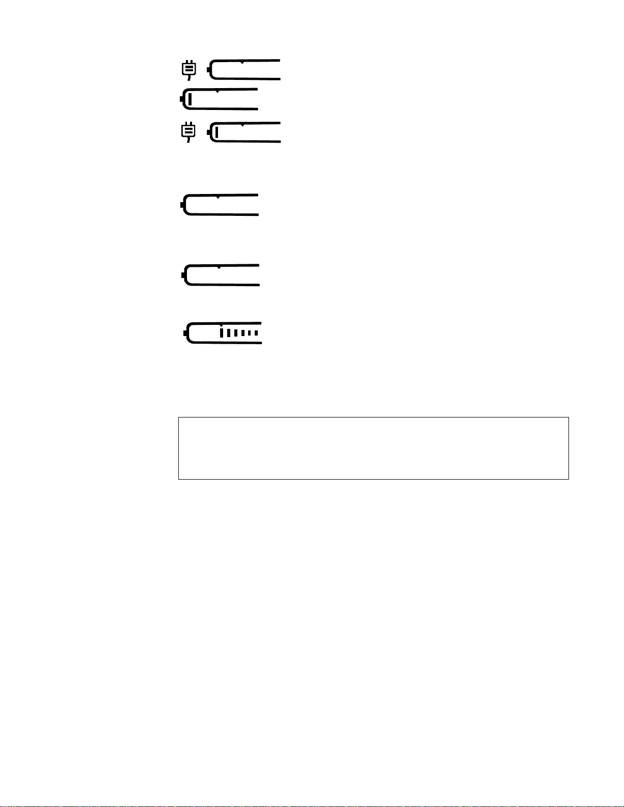
The battery status indicator reflects the state of the main or secondary battery in
the computer when the computer is off.
No indicator means there is no battery (main or secondary) in the computer, or
if present, the battery has been discharged.
System Overview 1-5
Page 14
•
The AC power indicator with the battery status in-
dicator means the battery is defective.
•
An indicator with one bar on the left means a battery is
too hot. Allow the battery to cool to room temperature.
The AC power indicator with the battery status in-
dicator and one bar means that the battery is too
hot (60
°
C [140
°
F] or more) to start charging. Charg-
ing starts automatically when the battery cools to
below 45
°
An indicator with no bars means that battery power is
low (about 90 percent depleted). This is the first low-
battery indication and the computer warns the user
with three short, audible beeps. There are about
10 minutes of battery life remaining.
A blinking indicator with no bars means that battery
power is critically low (about 95 percent depleted) and
needs recharging. There are about 5 minutes of battery
life remaining.
An indicator with bars on the right side of the icon
indicates the percentage of battery life remaining.
Each bar equals 10 percent of battery life.
•
C.
•
•
•
Battery Charge Gauge
CAUTION: If only one or none of the charge-level indicator lights are lit,
the battery is almost completely discharged. Do not use the battery
unless the comput er is c onn ec ted to AC p ower or un less you install a second charged battery.
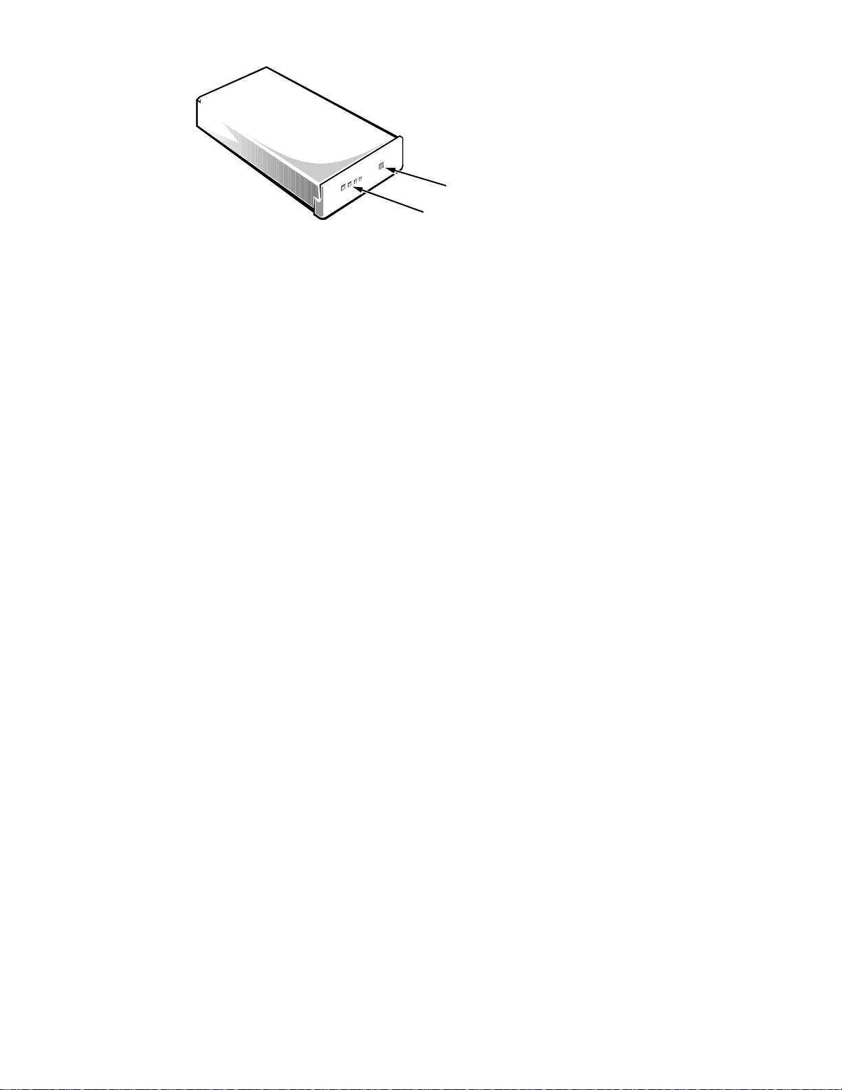
There is a battery charge gauge on the main and secondary battery. The charge
gauge has four charge-level indicator lights that indicate how much battery
charge remains. Each light indicates approximately 25 percent battery charge.
Press the status button to the right of the lights to check the total battery char ge.
If none of the lights are on, the battery has no charge left.
1-6 Dell Inspiron 3000 Series Service Manual
Page 15
p
g
status button
indicator lights
Figure 1-4. Battery Charge Gauge
NOTE: Figure 1-4 shows a main battery. For the secondary battery, the same
button and lights are present, but are located on top of the battery and can be
seen only when the secondary battery is out of the computer.
S
ystem Power
The power button controls power to the system. The computer receives power
from either the AC adapter connected to an AC power source or from up to two
batteries. If you use the AC adapter, constant power is available to the com-
uter. If you use one or two batteries, the system has built-in power
management features that extend battery life by removing power from parts of
the computer that are not being used.
Power Conservation
Attach the AC power adapter to the computer, whenever possible, to conserve
battery power. When the AC adapter is attached, th e battery is charged while the
computer uses AC power.
The Power Menu of the Setup program has power conservation features. To
open the Main Menu of the S etup program, Press <F2> during the boot process.
When activated, each power conservation feature turns off or slows down one
or more functions while the computer is idle. The power conservation features
are as follows:
•
Standby mode — To activate this feature, select the Standby Time-Out
option in the Power Menu of the Setup program. To deactivate the feature,
move the cursor or press any key on the built-in or external keyboard.
•
Save-to-RAM suspend mode — To activate this feature, press <Fn><Esc>
or set the Suspend Time-Out option in the Power Menu of the Setup pro-
ram. When save-to-RAM suspend mode is activated, the icons cycle
through the keyboard indicators area of the status display panel. To deactivate this feature, press the power button. The computer may take several
seconds to return to normal operation. Use the Resume On Modem Ring
option in the Power Menu of the Setup program to enable the computer to
automatically answer calls to external modems attached to the computer’s
serial port or to determine how long the computer remains in save-to-RAM
suspend mode before resuming normal operation.
System Overview 1-7
Page 16

Save-to-disk suspend mode — To activate this feature, press <Fn><a> (or
•
<Fn><q> on the French keyboard) or set the Suspend Time-Out option in
the Power Menu of the Setup program. To resume using the computer, press
the power button. The computer may take several seconds to return to normal operation. If you connect or remove devices while the computer is in
save-to-disk suspend mode, the computer automatically recognizes the
newly connected devices when it resumes normal operation. If you encounter problems with a PC Card after resuming from save-to-disk suspend
mode, remove and reinsert the PC Card. When the battery is nearly
depleted, the computer enters save-to-disk suspend mode to preserve system
data.
I
nterrupt Assignments
Table 1-1. Interrupt Assignments
IRQ Line Used/Available
IRQ0 Generated by the system timer
IRQ1 Generated by the keyboard controller to signal that the keyboard
output buffer is full
IRQ2 Cascade to second interrupt controller
IRQ3 Reserved
IRQ4 Reserved
IRQ5 Used by the audio controller
IRQ6 Generated by the diskette drive controller to indicate that the dis-
kette drive requires the attention of the microprocessor
IRQ7 Used by the parallel port
IRQ8 Generated by the system RTC
IRQ9 Software redirect to INT0A
IRQ10 Reserved
IRQ11 Reserved
IRQ12 Generated by the keyboard controller to indicate that the output
buffer of the integrated touch pad or external PS/2 mouse is full
IRQ13 Used by the math coprocessor on the microprocessor
IRQ14 Generated by the hard-disk drive to indicate that the drive
requires the attention of the microprocessor
IRQ15 Reserved
1-8 Dell Inspiron 3000 Series Service Manual
Page 17

T
echnical Specifications
Table 1-2. Technical Specifications
Microprocessor
Microprocessor type Inspiron 3000 M166ST, M200ST, M233ST,
M233XT, and M266XT: Intel Pentium microprocessor with MMX technology
Inspiron 3200 D233XT and D266XT: Intel
Pentium II microprocessor with MMX
technology
Microprocessor speed Inspiron 3000 M166ST, M200ST, M233ST,
M233XT, and M266XT: 166, 200, 233, or
266 MHz
Inspiron 3200 D233ST, D233XT, and
D266XT: 233 or 266 MHz
Internal cache memory 32 KB
External cache 512-KB write-back SRAM (256-KB write-back
SRAM for the M166ST)
Math coprocessor internal to the microprocessor
Chip Set and Bus
System chip set Inspiron 3000 M166ST, M200ST, M233ST,
M233XT, and M266XT: Intel 430TX PCIset
Inspiron 3200 D233ST , D233XT , and D266XT:
Intel 440BX PCIset
Data bus width 64 bits
DRAM bus width 64 bits
Address bus width 32 bits
Flash EPROM 2 Mbits
PC Card
PCI controller Texas Instruments PCI 1131 cardbus controller
PC Card connectors two (supports two type I or type II cards or one
type III card)
Cards supported 3.3- and 5-V
System Overview 1-9
Page 18

Table 1-2. Technical Specifications
(continued)
PC Card
(continued)
PC Card connector size 68 pins
Data width (maximum) 32 bits
Memory
Architecture SDRAM
Memory module
16-, 32-, and 64-MB SODIMMs
capacities
Standard RAM 32 MB (16 MB of nonremovable memory on the
main board and a 16-MB 3.3-V memory module
in one of the two memory module sockets on the
main board).
Maximum RAM 144 MB
Memory access time/
clock frequency 83 MHz
BIOS address F000:0000
Connectors
Serial (DTE) one 9-pin connector; 16,550-compatible UAR T,
16-byte buffer
Parallel one 25-hole connector; normal (unidirectional),
bidirectional, EPP 1.9, or ECP
Monitor one 15-hole connector
PS/2 keyboard/mouse one 6-pin mini-DIN
Infrared one IrDA 1.1-compliant port
Expansion connector 240 pins
Audio microphone; headphones/speaker; line-in
USB one 4-pin connector
1-10 Dell Inspiron 3000 Series Service Manual
Page 19

Table 1-2. Technical Specifications
Audio
(continued)
Audio type Sound Blaster Pro-compatible voice and
music functions
Audio controller Crystal 4237B
Conversion 16 bit (stereo analog-to-digital and
digital-to-analog)
FM music synthesizer 20-voice, 72-operator
Interfaces:
Internal ISA bus
External microphone (minijack, mono);
headphones/speaker (minijack);
line-in
Internal speaker amplifier 1.5 W
Controls volume can be controlled through key combina-
tions and software application menus
Video
Video type 64-bit (128-bit hardware accelerated) PCI
Video controller (M166ST,
M200ST , M233ST, M233XT ,
M266XT) NeoMagic 2160
Video controller (D233ST,
D233XT, D266XT) NeoMagic 2160B
Video memory 2 MB equivalent
12.1-Inch Display
Type (M166ST, M200ST,
M233ST, D233ST) active-matrix color (TFT)
Dimensions:
Height 184.5 mm (7.3 inches)
Width 246.0 mm (9.7 inches)
Diagonal 307.5 mm (12.1 inches)
Maximum resolution 800 x 600 pixels; 16 million colors
Response time (typical) 30 ms
System Overview 1-11
Page 20

Table 1-2. Technical Specifications
(continued)
12.1-Inch Display
(continued)
Operating angle 0° (closed) to 180°
Dot pitch 0.264 mm
Power consumption 2.35 W
Controls brightness can be controlled through key
combinations
13.3-Inch Display
Type (M233XT, M266XT,
D233XT, D266XT) active-matrix color (TFT)
Dimensions:
Height 203 mm (8.0 inches)
Width 271 mm (10.7 inches)
Diagonal 338 mm (13.3 inches)
Maximum resolution 1024 x 768 pixels; 64,000 colors
Response time (typical) 30 ms
Operating angle 0° (closed) to 170°
Dot pitch 0.264 mm
Power consumption 3.9 W
Controls brightness can be controlled through key
combinations
Keyboard
Number of keys 87 (U.S. and Canada); 88 (Europe); 88 (Japan)
Key travel 3.0 ± 0.5 mm (0.12 ± 0.02 inch)
Key spacing 19.1 mm (0.75 inch)
Layout QWERTY/AZERTY/Kanji
Touch Pad
Interface PS/2-compatible
X/Y position resolutions
(graphics table mode) 20 points/mm (500 points/inch)
1-12 Dell Inspiron 3000 Series Service Manual
Page 21

Table 1-2. Technical Specifications
(continued)
Touch Pad
(continued)
Size:
Thickness 4.65 mm (0.18 inch) at highest component
Width 64-mm (2.52-inch) sensor-active area
Height 47.0-mm (1.85-inch) rectangle
with 0.5-mm (0.02-inch) tabs
Weight 15 g (0.52 ounce) ± 0.5 g (0.001 ounce)
Power:
Supply voltage 5 V ± 10%
Supply current 4 mA (maximum operating)
Main Battery
Type lithium ion
Dimensions:
Height 23.0 mm (0.9 inch)
Depth 161.5 mm (6.4 inches)
Width 73.4 mm (2.9 inches)
Weight 0.41 kg (0.9 lb)
Voltage 14.4 VDC
Capacity 39 WH
Charge time (approximate):
1
Computer on 2.5 hours
Computer off 1.5 hours
Operating time (approximate,
with no power management
features enabled)
1
2.5 to 3.5 hours with one battery;
5 to 7 hours with two batteries
Life span (approximate)
1
500 discharge/charge cycles
Temperature range:
Charge 0° to 40°C (32° to 104°F)
Discharge 0° to 60°C (32° to 140°F)
Storage –20° to 50°C (–4° to 122°F)
1
Battery performance features such as charge time, operating time, and life span can vary according to
the conditions under which the computer and ba ttery are used.
System Overview 1-13
Page 22

Table 1-2. Technical Specifications
AC Adapter
(continued)
Input voltage 90 to 264 VAC
Input current (maximum) 1.5 A at 90 VAC, full load
Input frequency 47 to 63 Hz
Output current 2.4 A (continuous)
Output power 45 W
Rated output voltage 19 VDC
Physical:
Height 29.6 mm (1.17 inches)
Width 60.0 mm (2.36 inches)
Depth 105 mm (4.13 inches)
Weight (with cables) 0.3 kg (0.66 lb)
Temperature range:
Operating 5° to 35°C (41° to 95°F)
Storage –20° to 50°C (–4° to 122°F)
Physical (Computer)
M166ST, M200ST,
M233ST, D233ST:
Height 42 mm (1.65 inches)
Width 299 mm (11.77 inches)
Depth 234 mm (9.21 inches)
Weight
2
2.8 kg (6.2 lb)
M233XT, M266XT,
D233XT, D266XT:
Height 51.5 mm (2.03 inches)
Width 303 mm (11.93 inches)
Depth 234 mm (9.21 inches)
Weight
2
Includes hard-disk drive, diskette drive, battery, and two PC Card blanks.
2
3.1 kg (6.8 lb)
1-14 Dell Inspiron 3000 Series Service Manual
Page 23

Table 1-2. Technical Specifications
Environmental (Computer)
(continued)
Temperature:
Operating 5° to 35°C (41° to 95°F)
Storage –20° to 50°C (–4° to 122°F)
Relative humidity 10% to 90% (noncondensing)
Maximum vibration:
Operating 0.5 GRMS using a random-vibration spectrum
that simulates air/truck shipment
Storage 1.1 GRMS using a random-vibration spectrum
that simulates air/truck shipment
Maximum shock:
3
Operating 1.52 m/sec (60 inches/sec)
(less than or equal to a pulse width of 2 ms)
Storage 2.03 m/sec (80 inches/sec)
(less than or equal to a pulse width of 2 ms)
Altitude:
Operating 0 to 3048 m (0 to 10,000 ft)
Storage 0 to 12,192 m (0 to 40,000 ft)
3
Measured with the hard-disk drive in head-parked position.
System Overview 1-15
Page 24

1-16 Dell Inspiron 3000 Series Service Manual
Page 25

Chapter 2
Initial Procedures
his chapter describes initial procedures that can help you diagnose a com-
T
puter problem. These procedures can often reveal the source of a problem or
indicate the correct starting point for troubleshooting the computer. Dell recommends that you perform these initial procedures in the order they are presented.
I
nitial User Contact
When you first contact a user who has a problem, ask the user to describe the
problem and the conditions under which it occurs. A verbal description can
often indicate the cause of a problem or indicate the appropriate troubleshooting
procedure to use. After the user describes the problem, follow these steps:
1. Ask the user to back up any data on the hard-disk drive if the computer’s
condition permits.
See the “Maintaining Your Computer” section of the online System’s User’s
Guide.
2. Ask the user to try to duplicate the problem by repeating the operations he
or she was performing at the time the problem occurred.
Can the user duplicate the problem?
Yes. Proceed to step 3.
No. Proceed to the next section, “Visual Inspection.”
3. Observe the user to determine whether he or she is making an error, such as
typing an incorrect key combination or entering a command incorrectly.
Is the problem a result of user error?
Yes. Instruct the user in the proper procedure or direct him or her to the
appropriate user documentation for a description of the correct procedure.
No. Proceed to the next section, “Visual Inspection.”
V
isual Inspection
The visual inspection consists of a quick inspection of the exterior of the computer and any attached peripherals, including making any necessary corrections.
For information about the proper removal and installation of computer
Initial Procedures 2-1
Page 26

components, as instructed in the following procedure, see Chapter 4, “Removing and Replacing Parts.”
CAUTION: Before you proceed with the visual inspection, ensure that
the user has saved all open files and exited all open application programs
if possible.
To perform a visual inspection, follow these steps:
1. Determine the power state of the computer.
If the display is on, go to step 2.
Check the status display window to determine the status of the computer. If
the display is off, press the power key to verify that the computer is not in
suspend or standby mode. Then go to step 2.
2. Turn off any attached peripherals, and then shut down the computer.
3. Verify that the exterior of the computer is free of any obvious physical
damage.
4. If the computer is operating from an AC adapter, verify the following:
a. The AC adapter’s AC power cable is connected to both the AC adapter
and the wall outlet. The AC adapter’s LED should be on.
b. The AC adapter’s DC power cable is properly connected to the com-
puter’s AC adapter connector.
c. The AC adapter and cables are free of any obvious physical damage.
5. If the computer is operating from battery power, remove any installed batteries, verify that they are free of any obvious physical damage, and then
reinsert the batteries into their respective compartments. Press the test button located on each battery to see if there is a charge.
6. Remove the diskette drive (if installed), verify that it is free of any obvious
physical damage, and then reinsert the drive into its compartment.
7. Remove any installed PC Cards from the PC card slot, verify that they are
free of any obvious physical damage, and then reinsert the card(s) into the
PC card slot.
8. If there is a memory area problem and the computer has memory modules,
remove the memory modules from the main board, verify that they are free
of any obvious physical damage, and then reinstall the modules.
9. Raise the LCD display, and verify that the computer is free of any
obvious physical damage.
10. Verify that the keyboard is free of any obvious physical damage and that its
keys operate freely.
11. Verify that the touch pad and its associated buttons operate freely.
12. If an external monitor is connected, verify the following:
a. The monitor’s interface cable is properly attached to the external-
monitor connector on the computer’s I/O panel.
2-2 Dell Inspiron 3000 Series Service Manual
Page 27

b. The monitor’s power cable is attached to a power source and is free of
any obvious physical damage.
c. The monitor and its interface cable are free of any obvious physical
damage.
d. The monitor’s controls are set according to the instructions in the docu-
mentation for the monitor.
13. If an external mouse is connected, verify the following:
a. The mouse is properly connected to the keyboard/keypad/mouse con-
nector on the computer’s I/O panel.
b. The mouse and its cable are free of any obvious physical damage.
c. The mouse’s ball and pushbuttons operate freely.
14. For any attached serial or parallel devices, verify the following:
a. The device’s interface cable connector is correctly attached to the appro-
priate port connector on the computer’s I/O panel.
b. The captive screws that secure the connectors at each end of the inter-
face cable are secure enough to ensure a firm connection.
c. The attached device and its interface cable are free of any obvious phys-
ical damage.
15. Turn on any attached peripherals and then the computer.
Does the problem recur?
Yes. Go to the next section, “Observing the Boot Routine.”
No. No further steps are necessary.
O
bserving the Boot Routine
After you perform a visual inspection as described in the previous section, boot
the computer from a diagnostics diskette and, while the boot routine is running,
observe the computer for any indications of problems.
NOTE: To prevent possible damage to the original diagnostics diskette, always
use a backup copy of the diagnostics diskette when servicing a user’s computer.
Dell recommends that users make copies of the Dell Diagnostics Diskette. For
instructions, see “Before You Start Testing” in Chapter 4 of the Dell Inspiron
3000 Reference and Troubleshooting Guide.
To observe the boot routine, follow these steps:
1. Turn off the computer and any attached peripherals.
2. Insert a diagnostics diskette into the diskette drive. Turn on all peripherals
and then the computer.
3. Watch the indicators at the top of the keyboard. Depending on how your
computer is configured, after various indicators flash momentarily in the
status display panel, some indicators should light up and remain on.
Initial Procedures 2-3
Page 28

Do these indicators light up within seconds after the boot routine starts?
Yes. Go to step 4.
No. Troubleshoot the power subsystem.
4. While the boot routine is running, observe the computer for any of the
following:
Diskette-drive and hard-disk drive access indicator activity
•
These indicators light in response to data being transferred to or from the
drives. If either of these indicators fails to light during the boot routine,
troubleshoot the diskette drive or hard-disk drive subsystem, as
appropriate.
System error messages
•
These messages can indicate problems or provide status information. If a
system error message is displayed, refer to Table 3-2.
Beep codes
•
A beep code is a series of beeps that indicates an error condition. If the
computer emits a beep code, refer to Table 3-1.
NOTE: The computer beeps once shortly after the system boots . T his be ep
is normal and not part of a beep code.
Any unusual sounds
•
5. Observe the display for the Diagnostics Menu of the Dell Diagnostics.
Does the Diagnostics Menu appear on the display?
Yes. See “Running the Dell Diagnostics” in Chapter 3.
No. Go to step 6.
6. Insert another copy of the diagnostics diskette into the diskette drive, and
reboot the computer.
Does the Diagnostics Menu appear on the display?
Yes. See “Running the Dell Diagnostics” in Chapter 3.
No. Go to the next section, “Eliminating Resource Conflicts.”
E
liminating Resource Conflicts
Devices within or connected to the computer may require dedicated memory
spaces, interrupt levels, and/or DMA channels. Because different devices can be
configured at different times, it is possible that the same resource is assigned to
two or more devices.
Disconnect all peripherals and remove all PC Cards to make sure that the computer failure is not caused by faulty devices.
2-4 Dell Inspiron 3000 Series Service Manual
Page 29

If you suspect that resource conflicts might exist, check the computer and reassign the resources as necessary. For more information about resolving conflicts,
see Chapter 3, “Troubleshooting Your Computer,” in the Reference and Tr ouble-
shooting Guide.
G
etting Help
If none of the procedures in this chapter reveal the source of the problem or lead
to the proper troubleshooting steps for determining the source of the problem,
contact Dell for technical assistance. For instructions, see Chapter 5, “Getting
Help,” in the Reference and Troubleshooting Guide or the “Contacting Dell”
section of the online System User’s Guide.
Initial Procedures 2-5
Page 30

2-6 Dell Inspiron 3000 Series Service Manual
Page 31

Chapter 3
Beep Codes and Error Messages
his chapter describes beep codes and system error messages that can occur
T
during system start-up or, in the case of some failures, during normal computer
operation. The tables in this chapter list faults that can cause a beep code or system error message to occur and the probable causes of the fault in each case.
If a faulty computer does not emit beep codes or display system error messages
to indicate a failure, you should load the diagnostics and run the appropriate
tests to help isolate the source of the problem. See “Running the Dell Diagnostics” found later in this chapter.
P
OST Beep Codes
If the display cannot display error messages during POST, the computer may
emit a series of beeps that identify the problem or that can help you identify a
faulty component or assembly . The following table lists the beep codes that may
be generated during POST. Most beep codes indicate a fatal error that requires
replacement of the main board or other corrective actions before the computer
can operate.
Beep Codes and Error Messages 3-1
Page 32

prop
Table 3-1. POST Beep Codes
Beep Code Error Probable Causes
1-2 Memory module not being
erly identified or used
Faulty memory module or
faulty main board
1-2-2-3 ROM BIOS checksum failure Faulty main board
1-3-1-1 DRAM refresh failure Faulty main board
1-3-1-3 Keyboard controller test
failure
1-3-4-1 RAM failure on address line
nnnn
1-3-4-3 RAM failure on data bits
nnnn
of high byte on memory
Faulty keyboard or faulty
main board
Faulty memory module or
faulty main board
Faulty memory module or
faulty main board
bus
1-4-1-1 RAM failure on data bits
nnnn
of low byte on memory
Faulty memory module or
faulty main board
bus
2-1-2-3 Check ROM copyright notice
Faulty main board
failure
2-2-3-1 Interrupt mask register failure Faulty main board
S
ystem Error Messages
The following table lists (in alphabetical or der) system err or messages that may
appear on the display during the boot routine or during normal computer
operation.
Table 3-2. System Error Messages
Message Definition Probable Causes
Diskette drive A
error
Connector loose or diskette faulty. Cannot
access diskette drive.
Faulty or incorrectly
inserted diskette in
drive. Faulty diskette
drive. Faulty main
board. Faulty or loose
external cable.
Extended RAM
failed at offset:
nnnn
Extended memory not
configured properly or
failed at memory
address
nnnn
.
Faulty or improperly
seated memory module. Faulty main board.
3-2 Dell Inspiron 3000 Series Service Manual
Page 33

Table 3-2. System Error Messages
Message Definition Probable Causes
(continued)
Failing bits:
nnnn
Fixed disk 0
failure
Fixed disk controller failure
Incorrect drive A
type—run Setup
Keyboard controller error
Memory failed at RAM
address nnnn.
Hard-disk drive not
responding to
commands from
computer.
Hard-disk drive or controller not responding to
commands from
computer.
Diskette drive not identified properly in the
Setup program.
Keyboard controller
faulty.
Faulty or improperly
seated memory module. Faulty main board.
Corrupted hard-disk
drive boot sector or
configuration file.
Faulty hard-disk drive.
Faulty main board.
Faulty hard-disk drive.
Faulty main board.
Incorrect drive
configuration. Faulty
connections. Faulty diskette drive. Faulty main
board.
Faulty keyboard
connection. Faulty keyboard. Faulty main
board.
Keyboard error
Operating system
not found
Parity check 1
nnnn
Parity check 2
nnnn
Keyboard not responding correctly.
Operating system cannot be found on
hard-disk drive or on
diskette in diskette
drive.
Parity error in system
bus at address nnnn.
Parity error in I/O bus
at address nnnn.
Built-in keyboard:
faulty keyboard or key
pressed while computer booting.
External keyboard:
cable or connector
loose. Faulty keyboard
or key pressed while
computer booting.
Incorrect drive
configuration. Operating system not installed
on hard-disk drive or
diskette drive not
bootable. Faulty connections. Faulty drive.
Faulty main board.
Faulty main board.
Faulty main board.
Beep Codes and Error Messages 3-3
Page 34
Table 3-2. System Error Messages
Message Definition Probable Causes
(continued)
Real time clock
error
Shadow RAM failed
at offset:
System battery is
dead—Replace and
run Setup
System cache
error—cache
disabled
System CMOS
checksum bad—run
Setup
System RAM failed
at offset: nnnn
nnnn
CMOS battery that
supports data stored in
NVRAM may be dead.
Shadow RAM failed at
address nnnn.
CMOS battery dead. Faulty CMOS battery
Primary cache failed. Faulty microprocessor.
CMOS has been corrupted or modified,
possibly by an application program that
changes data stored in
CMOS.
Memory not operating
correctly. System RAM
failed at address nnnn
in the 64-KB block at
which error was
detected.
Faulty battery. Faulty
main board.
Faulty or improperly
seated memory module. Faulty main board.
or main board.
BIOS has been updated.
Verify correct CMOS
settings, save, and exit.
Faulty or improperly
seated memory module. Faulty main board.
System timer
error
R
unning the Dell Diagnostics
CAUTION: To prevent damage to the original diagnostics diskette,
always use a backup copy of the diagnostics diskette when servicing a
user’s computer. Dell recommends th at user s make several cop ies of thi s
diskette to ensure that one is always available.
The Dell Diagnostics contains tests that aid in troubleshooting the computer.
The diagnostics diskette contains the following test groups:
RAM — Tests the main memory
•
System Set — Tests the primary functions of the main board
•
Video — Tests the video subsystem
•
Keyboard — Tests the keyboard subsystem
•
Timer circuit on main
board malfunctioning.
Faulty main board.
3-4 Dell Inspiron 3000 Series Service Manual
Page 35

Mouse — Tests the mouse/touch pad subsystem
•
Diskette Drives — Tests the diskette drive subsystem
•
Hard-Disk Drives (Non-SCSI) — Tests the IDE hard-disk drive subsystem
•
IDE CD ROM Drives — Tests a CD-ROM drive subsystem
•
Serial/Infrared Ports — Tests the serial communications port
•
Parallel Ports — Tests the parallel communications port
•
Audio — Tests the operation of the audio chip set
•
SCSI Devices — Tests a SCSI hard-disk drive subsystem
•
NOTE: This test does not apply to Dell Inspiron 3000 computers.
Network Interface — Tests a network controller and its associated interface
•
NOTE: This test does not apply to Dell Inspiron 3000 computers.
Before starting the Dell Diagnostics, you must configure the computer correctly . For more information, see “B efore You Start Testing” in Chapter 4 of the
Reference and Troubleshooting Guide.
To run the Dell Diagnostics completely, you must have an external diskette
drive with a diskette drive cable attached.
Follow these steps to start the diagnostics:
1. Install a CD-ROM drive in the options bay.
2. Attach the external diskette drive cable to the parallel port connector on the
back of the computer.
3. Turn off the computer.
4. Place a copy of the Dell Diagnostics Diskette in the diskette drive, and boot
the computer .
Starting the diagnostics causes the Dell logo screen to appear, followed by a
message indicating that the diagnostics is loading. Before the diagnostics loads,
a program tests the portion of main memory (RAM) required for loading the
diagnostics. If a main memory error is detected, a message appears on the
screen telling you a memory module has failed.
If no errors are found in main memory, the diagnostics loads, and the Diagnostics Menu appears. This menu lets you choose the following options or exit to
the MS-DOS® prompt:
Run Quick Tests — Runs preselected tests to quickly locate a computer fail-
•
ure or to indicate where further testing is needed to isolate a failure
Run All Tests — Runs all tests for a thorough test of the computer
•
Run Specific Tests — Tests a particular area or subsystem of the computer
•
Beep Codes and Error Messages 3-5
Page 36

3-6 Dell Inspiron 3000 Series Service Manual
Page 37

Chapter 4
Removing and Replacing Parts
his chapter provides procedures for removing and replacing components,
T
assemblies, and subassemblies.
Unless otherwise noted, each of the procedures in this chapter assumes the
following:
The computer and any attached peripherals are turned off and the peripher-
•
als are disconnected from the computer’s I/O panel.
A part can be replaced or installed by performing the removal procedure in
•
reverse order.
When performing the procedures in this chapter that require the display assembly to be open, use a book or something similar to support the display assembly.
The angle of the display assembly with respect to the base assembly should not
exceed 180 degrees for a 12.1-inch LCD and 170 degrees for a 13.3-inch LCD.
Also, assume that locations or directions relative to the computer are as shown
in Figure 4-1 unless otherwise specified in a procedure.
back of computer
right side left side
front of computer
Figure 4-1. Computer Orientation
R
ecommended Tools
Most of the procedures require the use of one or more of the following tools:
Small flat-blade screwdriver
•
Number 1 magnetized Phillips-head screwdriver
•
Antistatic grounding strap
•
Dental pick
•
Removing and Replacing Parts 4-1
Page 38
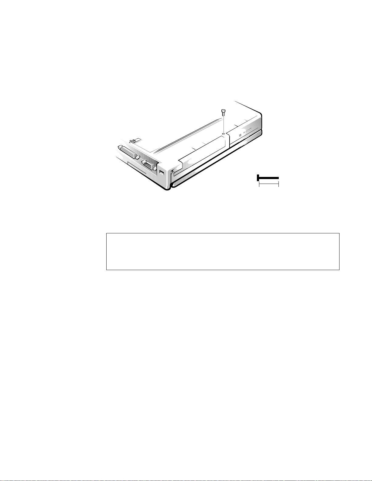
Small scribe (or Delrin [plastic] screwdriver)
g
B1
(screw B1 is 12 mm)
12 mm
•
Nut drivers (4 mm and 5 mm)
•
S
crew Identification and Tightenin
.
Figure 4-2. Screw Identification (Example)
CAUTION: It is essential that the correct length screw be used when
reinstalling a screw. Otherwise, hardware damage could result. Make
sure that the screw is properly aligned with its corresponding hole, and
avoid overtightening.
Where applicable, information about screw lengths is provided in illustrations.
Before installing a screw, match the screw to the screw length graphics provided
to check for correct length.
4-2 Dell Inspiron 3000 Series Service Manual
Page 39

P
recautionary Measures
Before performing any of the procedures in this chapter, read the following
warning.
WARNING FOR YOUR PERSONAL SAFETY AND PROTECTION
OF THE EQUIPMENT: Before you start to work on the computer, perform the following steps in the sequence indicated.
1. Turn off the computer and any attached peripherals.
2. Disconnect the computer and any attached peripherals from AC
power sources to reduce the potential for personal injury or shock.
3. Ground yourself by attaching an antistatic grounding strap to your
wrist and to an unpainted metal surface on the comp uter’ s I /O pan el.
If an antistatic grounding strap is not available, periodically discharge static electricity from your body by touching one of the
connectors on the I/O panel.
Follow these precautionary measures before removing or replacing any parts
that are described in this chapter:
1. Determine the power state of the computer.
If the display is on, go to step 2.
Check the status display window to determine the status of the computer. If
the display is off, press the power key to verify that the computer is not in
suspend or standby mode. Then proceed to step 2.
2. Turn off any attached peripherals, and then shut down the computer.
3. Disconnect the computer and any attached peripherals from AC power
sources to reduce the potential for personal injury or shock.
If the computer has an AC adapter, disconnect the adapter from the AC
power source, and then disconnect the AC adapter from the computer or
from the port replicator (see Figures 4-3 and 4-4).
Removing and Replacing Parts 4-3
Page 40
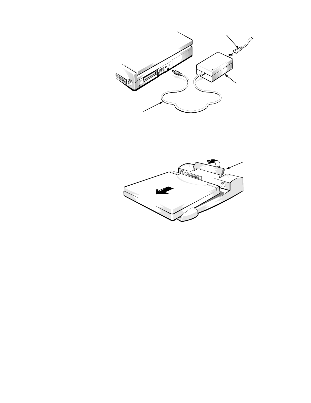
AC power cable
(to AC power source)
AC adapter
AC adapter cable
release handle
Figure 4-3. AC Adapter Removal
4. If the computer is connected to a port replicator, remove the computer from
the replicator.
Figure 4-4. Computer Removal From Replicator
5. Remove the main battery from the battery compartment.
Unlock the latch lock (see Figure 4-5). Slide the latch toward the back of the
computer (the latch does not move all the way to the lock groove). Keep
holding the latch with one hand while pulling the battery straight out to
release the battery. Then slide the battery out of the compartment.
4-4 Dell Inspiron 3000 Series Service Manual
Page 41
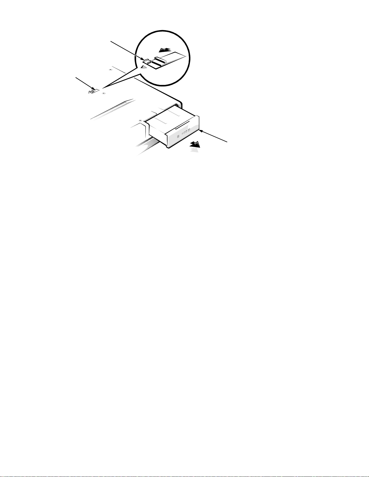
latch lock (unlocked position)
bottom of computer
battery latch
back of computer
Figure 4-5. Main Battery Rem oval
battery
Removing and Replacing Parts 4-5
Page 42
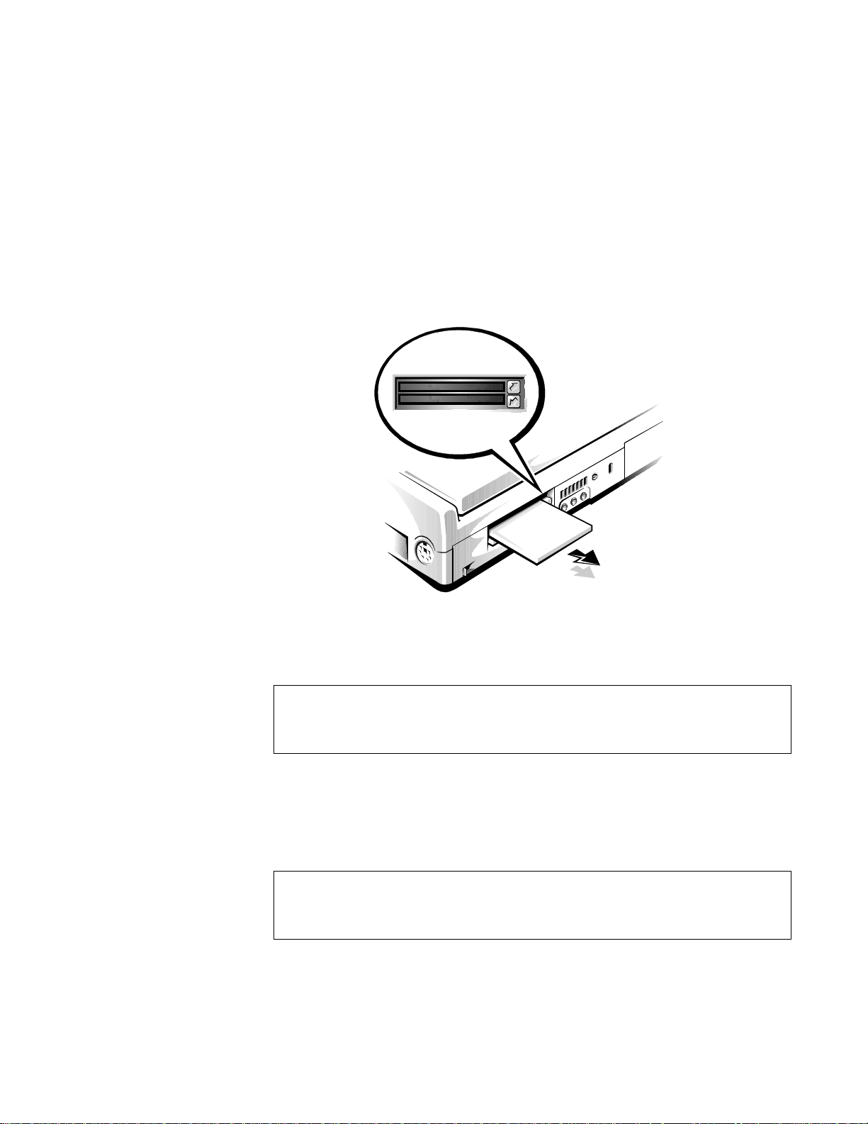
6. Remove any PC Cards.
To remove a PC Card from the top connector (see Figure 4-6), press the top
eject button (identified by an arrow pointing up) twice. To remove a PC
Card from the bottom connector, press the bottom eject button (identified by
an arrow pointing down) twice. If you are removing a type III card, press the
bottom eject button twice.
NOTES: The first time you press an eject button, the eject button itself pops
out. The second time you press the eject butt on, the PC Card is released and
extends slightly from the slot.
Grasp the end of the card, and pull it completely from the slot. Then install
one or both of the blanks provided with the computer to pr otect the PC Car d
connectors.
Figure 4-6. PC Card Removal
CAUTION: When handling the hard-disk drive, handle it gently and
don’t bump or drop the drive. Rough handling of the drive could
induce failure or loss of data.
7. Remove the hard-disk drive assembly.
Turn the computer over and remove the small rubber covers over screws
HD1 and HD2, then remove the screws. Pull the hard-disk drive straight out
of the computer (see Figure 4-7).
CAUTION: When the hard-disk drive is not in the computer, protect
the drive from exposure to static electricity by storing it in a harddisk drive case.
4-6 Dell Inspiron 3000 Series Service Manual
Page 43
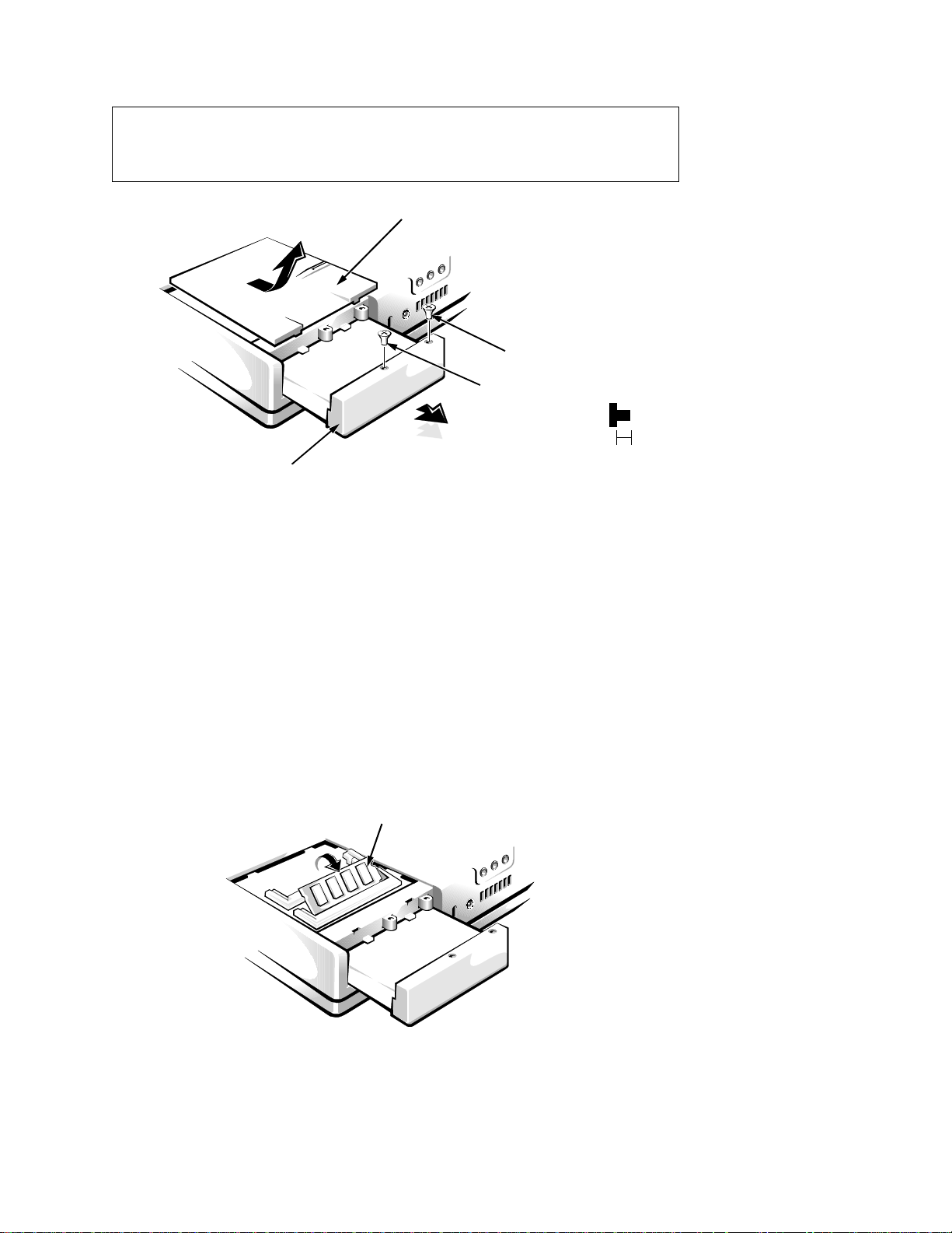
p
CAUTION: When the hard-disk drive is removed, the memory module cover is not secured. Use caution to avoid damage to the memory
modules or the cover.
bottom of computer
hard-disk
drive cover
memory module
cover
HD2
HD1
(screws HD1 and
HD2 are 3 mm)
Figure 4-7. Hard-Disk Drive Removal
8. Remove the memory module cover.
After the hard-disk drive is removed, lift the memory module cover off the
computer. Slide the cover out slightly and lift it up and away from the com-
uter (see Figure 4-7).
3 mm
When reinstalling the cover, place it over the memory module opening,
leaving about
-inch gap, then slide the cover into place.
1/4
9. Remove the memory modules.
Carefully spread apart the inner metal tabs of the memory module socket to
disengage the module from the socket (the module should pop up slightly).
Then lift the memory module away from the socket (see Figure 4-8).
memory module
bottom of computer
Figure 4-8. Removing a Memory Module
Removing and Replacing Parts 4-7
Page 44

10. Remove the diskette drive, secondary battery, CD-ROM drive, or
latch
bottom of computer
secondary battery
latch lock
(unlocked
position)
back of computer
options bay
DVD-ROM drive from the options drive bay.
Unlock the latch lock (see Figure 4-9). Slide the latch toward the back of the
computer; the latch does not move all the way to the lock groove. Keep
holding the latch with one hand while pulling the device (diskette drive, secondary battery, CD-ROM drive, or DVD-ROM drive) straight out of the
options bay with the other.
Figure 4-9. Diskette Drive, Secondary Battery , CD-ROM Drive, or
DVD-ROM Drive Removal
NOTE: If the computer is booted with a diskette drive or secondary battery
in the options bay, you must reboot after installing the CD-ROM or DVDROM drive in the options bay.
4-8 Dell Inspiron 3000 Series Service Manual
Page 45
Z
IF Connectors
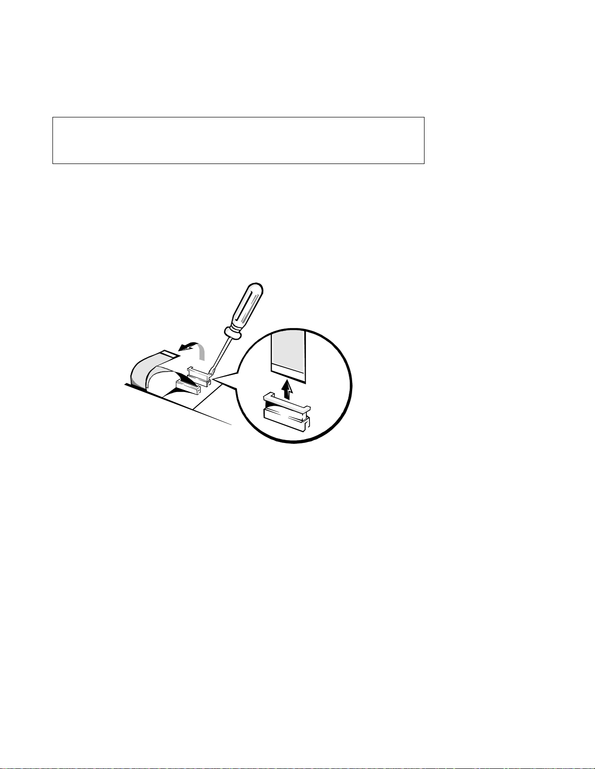
Some of the computer’s interface connectors are zero insertion force (ZIF)
connectors. These connectors are not removable; they must be released to
disconnect a cable from them.
CAUTION: ZIF connectors are fragile. To avoid breaking the connectors, touch them carefully. Do not apply too much pressure to the
movable part of the connector when opening or closing it.
To disconnect a cable from a ZIF connector, follow these steps:
1. Insert a small flat-blade screwdriver or dental pick under the movable part
of the connector (see Figure 4-10).
For most ZIFs, carefully pry up first one end of the movable part of the connector and then the other end. Some ZIFs (keyboard connector on the main
board) may need to be lifted in the center.
.
Figure 4-10. Releasing a ZIF Connector
2. Pull up gently on the movable part of the connector until the cable is
released.
3. Grasp the cable and pull it out of the connector.
To reconnect an interface cable to a ZIF connector, follow these steps:
1. Use the flat-blade screwdriver to open the movable part of the ZIF
connector.
2. Orient the end of the cable with the ZIF connector, and insert the end of the
cable into the connector.
3. While holding the cable in place, close the ZIF connector.
To ensure a firm connection, make sure the ZIF connector is completely
closed.
Removing and Replacing Parts 4-9
Page 46
E
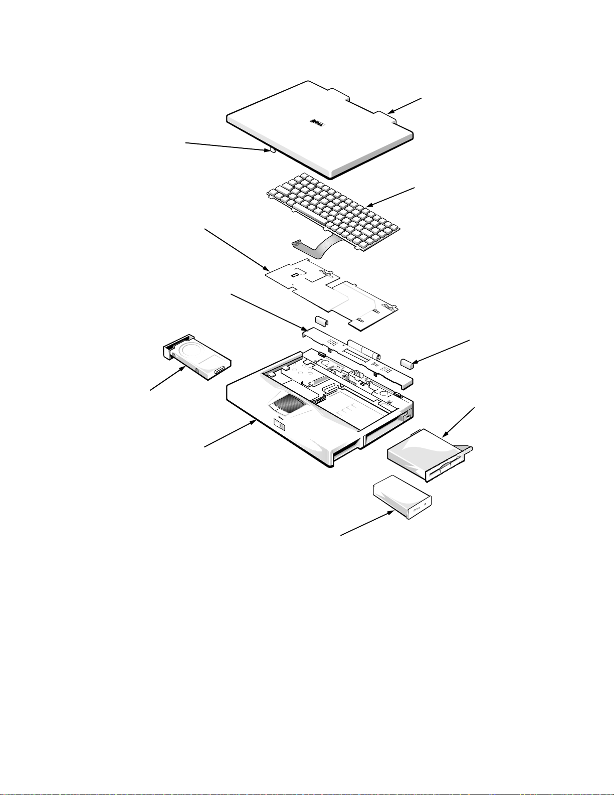
xploded Views of Components and Assemblies
LCD panel
assembly
latch
keyboard
heat sink
connector cover
hinge covers (2)
hard-disk drive
base
assembly
main battery
Figure 4-11. Exploded View—Computer
diskette drive,
secondary battery,
CD-ROM drive, or
DVD-ROM drive
4-10 Dell Inspiron 3000 Series Service Manual
Page 47
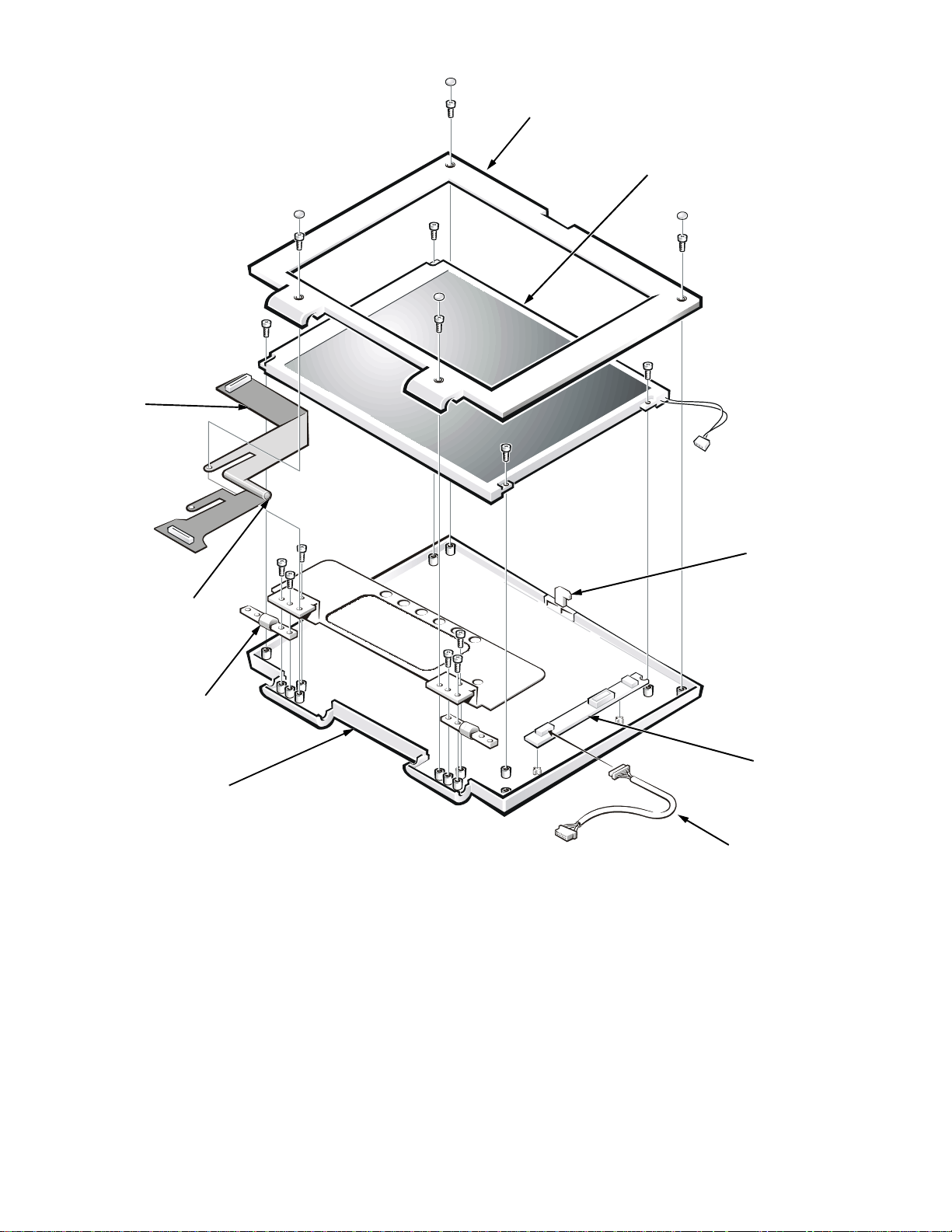
.
LCD panel
flex cable
front bezel
LCD panel
bobbin (adhered
to LCD flex cable)
hinges (2)
back
cover
Figure 4-12. Explod ed View—12.1-Inch LCD Assembly
latch
inverter
board
inverter
board
connector
Removing and Replacing Parts 4-11
Page 48
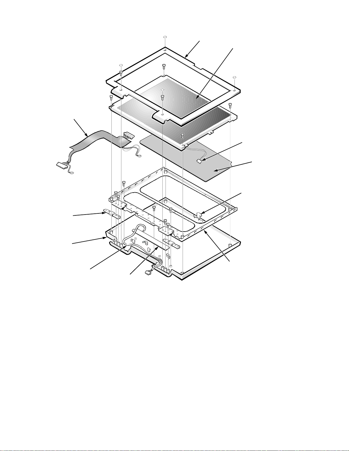
LCD panel cable
harness (captured by
the bracket)
front bezel
LCD panel
LCD-to-inverter
cable
EPE foam
latch
hinges (2)
back cover
inverter
board cable
inverter board
bracket
NOTE: The inverter board is installed wi th the component side down, next to the
back cover.
Figure 4-13. Exploded View—13.3-Inch LCD Assembly
4-12 Dell Inspiron 3000 Series Service Manual
Page 49
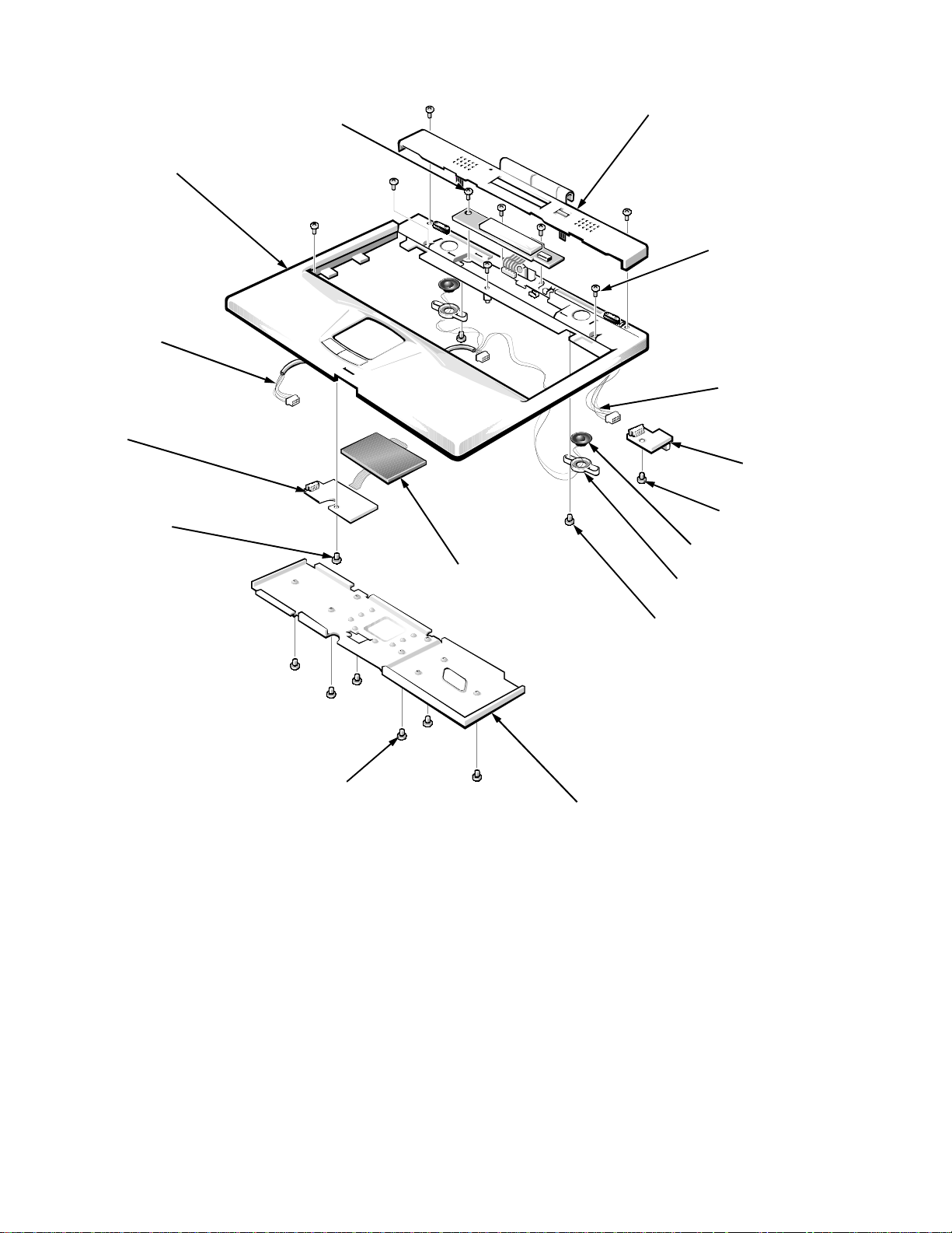
status display panel screws (3)
palmrest
assembly
touch pad button
board cable
touch pad button
board
connector cover
cover screws (6)
I/R board cable
I/R board
touch pad button
board screw
touch pad
hard-disk drive
heat sink screws (6)
Figure 4-14. Explod ed View—Palmrest Assembly
I/R board screw
speakers (2)
plastic housings (2)
speaker screws (2)
hard-disk drive
heat sink
Removing and Replacing Parts 4-13
Page 50
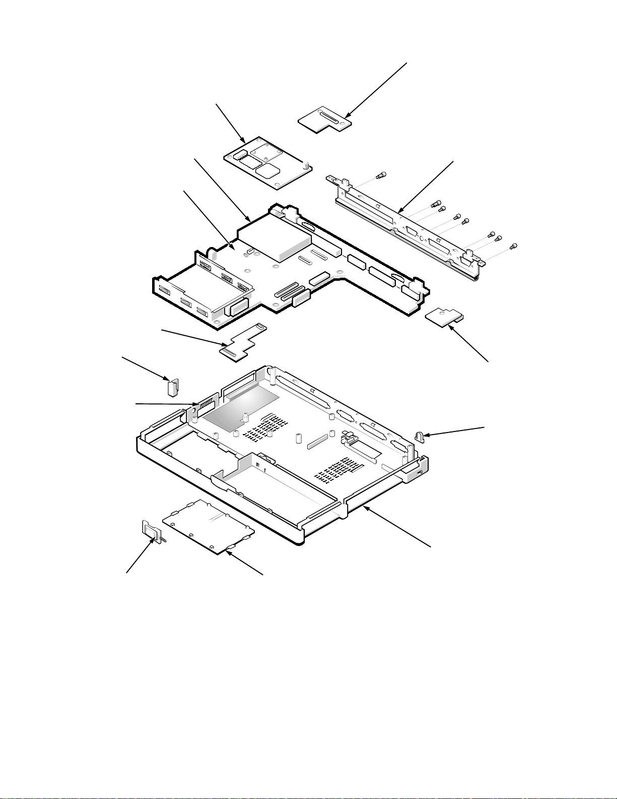
.
processor board
LVDS board
(13.3-inch
LCD only)
audio board
Kensington
lock plate
audio bezel
PC Card cage
main board
I/O panel bracket
USB board
IR lens
latch
assembly
Figure 4-15. Exploded View—Base Assembly
4-14 Dell Inspiron 3000 Series Service Manual
base
assembly
memory module cover
Page 51

F
actory Repair Parts and Assemblies
This section contains a parts list and procedures for removing and replacing factory components and subassemblies. This information is provided for reference
only. Dell does not recommend removal and replacement of these parts in the
field.
Table 4-1 lists the factory repair parts and assemblies available for the computer. Some parts may only be available as part of a kit or assembly. The
subsections in this chapter provide instructions for removing and replacing
these parts and assemblies. An asterisk (*) identifies those parts or assemblies
that are replaceable by a customer.
.
Table 4-1. Factory Repair Parts and Assemblies
Part or Assembly Name Order Name
AC Adapter/Power Cables
AC Adapter, service kit
AC Adapter
*
*
CUS,ADPT,AC,EXT,19V,I3000,US
ADPT,AC,EXT,19V,45W,NBK,I3000
Cable, power, U.S. CORD,PWR,110V,6F,AC ADPT,US
Batteries
Battery, main, service kit
*
CUS,BTRY,MAIN,40W,LIION,I3000
Battery, main, 40-WH BTRY,MAIN,40W,LIION,NBK,
I1300
Battery, secondary
*
CUS,BTR Y,2ND,40W,LIION,I3000
Battery, secondary KIT,BTRY,2ND,40W,LIION,I1300
BIOS
Door, BIOS, service kit CUS,DOOR,PLSTC,BIOS,NBK,
I3000
Door, BIOS DOOR,PLSTC,BTM,BIOS,NBK,
I3000
BIOS, flash, service kit (M166ST,
CUS,FLASH,UPG,I3000
M200ST, M233ST, M233XT,
M266XT)
BIOS, flash, service kit (D233ST,
D233XT, D266XT)
* Customer-replaceable unit (CRU)
CUS,DSK,FLASH,BIOS,UPD,I3200
Removing and Replacing Parts 4-15
Page 52

Table 4-1. Factory Repair Parts and Assemblies
Part or Assembly Name Order Name
BIOS
(continued)
(continued)
Kit, BIOS flash (M166ST,
M200ST, M233ST, M233XT,
M266XT)
Kit, BIOS flash (D233ST,
D233XT, D266XT)
Base (with battery), 166-MHz,
12.1-inch LCD
Assembly (with battery),
166-MHz
Base (with battery), 200-MHz,
12.1-inch LCD
Assembly (with battery),
200-MHz
Base (with battery), 233-MHz,
12.1-inch LCD
Assembly (with battery),
233-MHz
KIT,FLASH,BIOS,UPG,F3,I3000
KIT,DSK,FLASH,BIOS,UPG,I3200
Base Assembly
BASE,I3000,M166ST,FD,BTRY,
AMF
ASSY,NBK,I3000,M166ST,AMF
BASE,I3000,M200ST,FD,BTRY,
AMF
ASSY,NBK,I3000,M200ST,AMF
BASE,I3000,M233ST,FD,BTRY,
AMF
ASSY,NBK,I3000,M233ST,AMF
Base (with battery), 233-MHz,
13.3-inch LCD
Assembly (with battery),
233-MHz
Base (with battery), 266-MHz,
13.3-inch LCD
Assembly (with battery),
266-MHz
Base (without battery), 166-MHz,
12.1-inch LCD
Assembly (without battery),
166-MHz
Base (without battery), 200-MHz,
12.1-inch LCD
Assembly (without battery),
200-MHz
BASE,I3000,M233XT,FD,BTRY,
AMF
ASSY,NBK,I3000,M233XT,AMF
BASE,I3000,M266XT,FD,BTRY,
AMF
ASSY,NBK,I3000,M266XT,AMF
BASE,NBK,I3000,M166ST,NO
BTRY
ASSY,NBK,I3000,M166ST,NO
BTRY
BASE,NBK,I3000,M200ST,NO
BTRY
ASSY,NBK,I3000,M200ST,NO
BTRY
4-16 Dell Inspiron 3000 Series Service Manual
Page 53

Table 4-1. Factory Repair Parts and Assemblies
Part or Assembly Name Order Name
(continued)
Base Assembly
Base (without battery), 233-MHz,
13.3-inch LCD
Assembly (without battery),
233-MHz
Base (without battery), 266-MHz,
13.3-inch LCD
Assembly (without battery),
266-MHz
Main Board
(continued)
BASE,NBK,I3000,M233XT,NO
BTRY
ASSY,NBK,I3000,M233XT,NO
BTRY
BASE,NBK,I3000,M266XT,NO
BTRY
ASSY,NBK,I3000,M266XT,NO
BTRY
Board assembly, main SYS,PLN,TFT,SDRAM,I3000,WWD
IC, keyboard BIOS (M166ST,
IC,BIOS,KYBD,NBK,I3000
M200ST, M233ST, M266ST,
M266XT)
IC, keyboard BIOS (D233ST,
IC,BIOS,KYBD,NBK,I3200
D233XT, D266XT)
Bracket, I/O BRKT,MET,I/O,NBK,I3000
Hinge block, right PLT,BRACE,HNG,LCD,RT,NBK,
I3000
Hinge block, left PLT,BRACE,HNG,LCD,LF,NBK,
I3000
Ground springs, PC Card cage SPR,GND,CAGE,PCMCIA,NBK,
I3000
Assembly, PC Card cage ASSY,CAGE,MTL,PCMCIA,I3000
M166ST board assembly, Pentium
166-MHz
ASSY,CRD,PRCR,NBK,I3000,
M166ST
Kit, thermal, M166ST ASSY,CRD,THRM,PRC,NBK,I3000
M166ST processor board,
Pentium 166-MHz
M200ST board assembly,
Pentium 200-MHz
PRM,2PP166AES,166M,MOBIL,
PRO
ASSY,CRD,PRCR,NBK,I3000,
M200ST
Kit, thermal, M200ST ASSY,CRD,THRM,PRC,NBK,I3000
M200ST processor board,
Pentium 200-MHz
PRM,2PP200AES,200M,MOBIL,
PRO
Removing and Replacing Parts 4-17
Page 54

Table 4-1. Factory Repair Parts and Assemblies
Part or Assembly Name Order Name
(continued)
Main Board
M233ST board assembly,
Pentium 233-MHz
(continued)
ASSY,CRD,PRCR,NBK,I3000,
M233ST
Kit, thermal, M233ST ASSY,CRD,THRM,PRC,NBK,I3000
M233ST processor board,
PRM,5PP233,233M,MOBIL,COMPA
Pentium 233-MHz
M233XT board assembly,
Pentium 233-MHz
ASSY,CRD,PRCR,NBK,I3000,
M233XT
Kit, thermal, M233XT ASSY,CRD,THRM,PRC,NBK,I3000
M233XT processor board,
PRM,5PP233,233M,MOBIL,COMPA
Pentium 233-MHz
M266XT board assembly,
Pentium 266-MHz
ASSY,CRD,PRCR,NBK,I3000,
M266XT
Kit, thermal, M266XT ASSY,CRD,THRM,PRC,NBK,I3000
M266XT processor board,
PRM,5PP266,266M,MOBIL,COMPA
Pentium 266-MHz
D233ST board assembly,
ASSY,PRM,5PP233,233M,512K,PII
Pentium II 233-MHz
Kit, thermal, D233ST KIT,THRM,PRC,NBK,I3200,MO-
BILE
D233ST processor board, Pen-
PRM,5PP233,233M,512K,PII
tium II 233-MHz
D233XT board assembly,
ASSY,PRM,5PP233,233M,512K,PII
Pentium II 233-MHz
Kit, thermal, D233XT KIT,THRM,PRC,NBK,I3200,MO-
BILE
D233XT processor board,
PRM,5PP233,233M,512K,PII
Pentium II 233-MHz
D266XT board assembly,
ASSY,PRM,5PP266,266M,512K,PII
Pentium II 266-MHz
Kit, thermal, D266XT KIT,THRM,PRC,NBK,I3200,MO-
BILE
D266XT processor board,
PRM,5PP266,266M512K,PII
Pentium II 266-MHz
4-18 Dell Inspiron 3000 Series Service Manual
Page 55

Table 4-1. Factory Repair Parts and Assemblies
Part or Assembly Name Order Name
CD-ROM Drive
(continued)
CD-ROM drive, 20X, service kit
CUS,CD,680M,I,INT,20X,I3000
*
CD-ROM drive, 20X ASSY,CD,680M,I,INT,20X,I3000
Button, eject BTN,EJCT,MET,CD,20X,NBK,I3000
Bracket, plastic BRKT,PLSTC,CD,20X,NBK,I3000
Cover, plastic CVR,PLSTC,CD,20X,NBK,I3000
Cable, flex CBL,FLEX,CD,20X,NBK,I3000
Door DOOR,PLSTC,CD,20X,NBK,I3000
CD-ROM drive, 24X ASSY,CD,680M,I,INT,24X,
TSHBA,I3000
CD-ROM drive CD,680M,I,INT24X,TOSHIBA
Screw SCR,M2X0.4+3FP-ZK
Door DOOR,PLSTC,CD,24X,NBK,I3000
Cover, plastic CVR,PLSTC,CD,24X,NBK,I3000
Bracket, plastic BRKT,PLSTC,CD,20X,NBK,I3000
Cable, flex CBL,FLEX,CD,24X,NBK,I3000
Diskette Drive Assembly
Diskette drive, internal/external,
service kit
*
CUS,FD,INT/EXT,NBK,I3000
Diskette drive assembly ASSY,FD,F3,INT/EXT,I3000,MITSU
Diskette drive FD,1.44M,F3,17MM,I3000,
MITSUMI
Case, plastic CVR,PLSTC,FD,NBK,I3000,
MITSUMI
Plate, top metal PLT,MET,TOP,FD,NBK,I3000
Plate, metal PLT,MET,CONT,FD,NBK,I3000
Plate, external metal PLT,MET,EXT,FD,NBK,I3000
Cable, flex CBL,FLEX,FD,NBK,I3000,MIT-
SUMI
* Customer-replaceable unit (CRU)
Removing and Replacing Parts 4-19
Page 56

Table 4-1. Factory Repair Parts and Assemblies
Part or Assembly Name Order Name
(continued)
Cable, service kit
Diskette Drive Assembly
*
CUS,CBL,FD,INT/EXT,I3000,US
(continued)
Cable, diskette drive KIT,CBL,FD,INT/EXT,I3000,US
Hard-Disk Drive Assemblies
Hard-disk drive, 2.1-GB, service kit* CUS,HD,2.1G,I,12.5MM,IBM,I3000
Assembly, hard-disk drive,
SUBASSY,HD,2.1G,I,12.5MM,I3000
2.1-GB
Hard-disk drive, 2.1-GB HD,2.1GB,I,F2,12.5MM,IBM,V2
Bracket, hard-disk drive BRKT,HD,PLSTC,12.5MM,STW
Screws, bracket SCR,M3.0x0.5x4,PHH,NPL
Insulator, metal INSUL,MET,BTM,HD,12.5MM,
STW
Hard-disk drive, 3.2-GB, service kit* CUS,HD,3.2G,I,12.5MM,IBM,I3000
Assembly, hard-disk drive,
SUBASSY,HD,3.2G,I,12.5MM,I3000
3.2-GB
Hard-disk drive, 3.2-GB HD,3.2GB,I,12.5MM,NBK,IBM
Bracket, hard-disk drive BRKT,HD,PLSTC,12.5MM,STW
Screws, bracket SCR,M3.0x0.5x4,PHH,NPL
Insulator, metal INSUL,MET,BTM,HD,12.5MM,
STW
Hard-disk drive, 4.0-GB, service kit*CUS,HD,4.0G,I,12.5MM,IBM,I3000
Assembly, hard-disk drive,
SUBASSY,HD,4.0G,I,12.5MM,I3000
4.0-GB
Hard-disk drive, 4.0-GB HD,4.0GB,I,12.5MM,NBK,IBM
Bracket, hard-disk drive BRKT,HD,PLSTC,12.5MM,STW
Screws, bracket SCR,M3.0x0.5x4,PHH,NPL
Insulator, metal INSUL,MET,BTM,HD,12.5MM,
STW
* Customer-replaceable unit (CRU)
4-20 Dell Inspiron 3000 Series Service Manual
Page 57

Table 4-1. Factory Repair Parts and Assemblies
Part or Assembly Name Order Name
(continued)
Hard-Disk Drive Assemblies
(continued)
Bracket, plastic BRKT,HD,PLSTC,12.5MM,NBK,
I3000
Plate, insulator, EMI INSUL,MET,BTM,HD,12.5MM,
I3000
Hinge Covers
Covers, hinge, service kit CUS,CVR,PLSTC,HNG,NBK,I3000
Covers, hinge HNG,PLSTC,CVR,LF/RT,NBK,
I3000
Keyboards
Keyboard, U.S. KYBD,87,US,NBK,I3000,JM
Keyboard, UK KYBD,88,UK,NBK,I3000,JM
Keyboard, Japan KYBD,88,JPN,NBK,I3000,JM
Keyboard, Germany KYBD,88,GER,NBK,I3000,JM
Keyboard, French KYBD,88,FR,NBK,I3000,JM
LCD Assemblies
LCD panel, active-matrix color
LCD,TFT,SVGA,12.1”,I1300,IBM
display (TFT), 12.1” IBM
Bezel, front, 12.1” IBM BZL,PLSTC,LCD,12.1,NBK,I3000
Cable, flex, 12.1” IBM CBL,FLEX,LCD,12.1,I3000,IBM
Hinges, display, 12.1” HNG,MET,LCD,12.1”,NBK,I3000
Bezel, back, 12.1” IBM CVR,BK,12.1,W/LTCH,I3000,IBM
Bumper, upper rubber, 12.1” BMPR,RBR,UPR,LCD,12.1”,I3000
Cable, inverter, 12.1” IBM CBL,WIRE,INVRTR,LCD,12.1,
I3000
Bracket, LCD panel, 12.1” IBM BRKT,MET,LCD,12.1,I3000,IBM
Screw, LCD panel SCR,M3.0X0.5+5FP-MC
Screw, bezel SCR,M2.5X0.45P+5FP-ZK
Washer WSHR,LLK,7X3X0.5,THIN,SPTE
Cover, lower rubber PAD,RBR,SCR,LWR,LCD,NBK,
I3000
Board, inverter CRD,INVRTR,12.1,I3000,IBM
Removing and Replacing Parts 4-21
Page 58

Table 4-1. Factory Repair Parts and Assemblies
Part or Assembly Name Order Name
(continued)
LCD Assemblies
LCD panel, active-matrix color
display (TFT), 12.1” Samsung
(continued)
LCD,TFT,SVGA,12.1”,I1300,
SMSNG
Bezel, front, 12.1” Samsung BZL,PLSTC,LCD,12.1,NBK,I3000
Cable, flex, 12.1” Samsung CBL,FLEX,LCD,12.1,I3000,
Hinges, display, 12.1” HNG,MET,LCD,12.1”,NBK,I3000
Bezel, back, 12.1” Samsung CVR,BK,12.1”,W/LTCH,I3000,
SMSNG
Bumper, upper rubber, 12.1” BMPR,RBR,UPR,LCD,12.1”,I3000
Cable, flex cable, Samsung CBL,WIRE,INVRTR,LCD,12.1,
I3000,SMSNG
Bracket, LCD panel, 12.1” Samsung BRKT,MET,LCD,12.1,I3000,
SMSNG
Screw, LCD panel SCR,M3.0X0.5+5FP-MC
Screw, bezel SCR,M2.5X0.45P+5FP-ZK
Washer WSHR,LLK,7X3X0.5,THIN,SPTE
Cover, lower rubber PAD,RBR,SCR,LWR,LCD,NBK,
I3000
Board, inverter CRD,INVRTR,12.1,I3000,SMSNG
LCD panel, active-matrix color
LCD,TFT,SVGA,13.3”,I1300,IBM
display (TFT), 13.3” IBM
Bezel, front, 13.3” IBM BZL,PLSTC,LCD,13.3,NBK,I3000
Hinges, display, 13.3” IBM HNG,MET,LCD,13.3”,NBK,I3000
Bumpers, inverter, 13.3” BMPR,RBR,INVRTR,13.3,NBK,
I3000
BMPR,RBR,INVRTR,13.3,IBM,
I3000
Cable, LCD discreet, 13.3” IBM CBL,WIRE,LCD,13.3,I3000,IBM
Cable, inverter, 13.3” IBM CBL,WIRE,INVRTR,LCD,13.3,
I3000,IBM
Bezel, back, 13.3” IBM CVR,BK,13.3,W/LTCH,I3000,IBM
Bracket, EPE, 13.3” IBM FOAM,SPCR,LCD,13.3”,NBK,
I3000,IBM
4-22 Dell Inspiron 3000 Series Service Manual
Page 59

Table 4-1. Factory Repair Parts and Assemblies
Part or Assembly Name Order Name
(continued)
LCD Assemblies
(continued)
Bracket, LCD panel, 13.3”, IBM BRKT,MET,LCD,13.3,NBK,I3000,
IBM
Screw, flex cable ground SCR,M2.5X0.45P+3F-NI
Bumper, upper rubber, 13.3” BMPR,RBR,UPR,LCD,13.3”,I3000
Screw, LCD panel SCR,M3.0X0.5+6FP-MC
Screw, bezel SCR,M2.5X0.45P+5FP-ZK
Cover, lower rubber PAD,RBR,SCR,LWR,LCD,NBK,
I3000
Board, inverter CRD,INVRTR,13.3,I3000,IBM
Spacer, 13.3” SHIM,WSHER,5X3X.3,THIN,NYL
LCD panel, active-matrix color
display (TFT), 13.3” Samsung
LCD,TFT,SVGA,13.3”,I3000,
SMSNG
Bezel, front, 13.3” Samsung BZL,PLSTC,LCD,13.3,NBK,I3000,
SMSNG
Hinges, display, 13.3” Samsung HNG,MET,LCD,13.3”,NBK,I3000
Bumper, inverter, 13.3” BMPR,RBR,INVRTR,13.3,NBK,
I3000
Cable, LCD discreet, 13.3” Samsung CBL,WIRE,LCD,13.3,I3000,SMSNG
Cable, inverter, 13.3” Samsung CBL,WIRE,INVRTR,LCD,13.3,
I3000,SAM
Bezel, back, 13.3” Samsung CVR,BK,13.3,W/LTCH,I3000,
SMSNG
Bracket, EPE, 13.3” Samsung FOAM,SPCR,LCD,13.3”,NBK,
I3000,SMSNG
Bracket, LCD panel, 13.3” Samsung BRKT ,MET,LCD,13.3,NBK,I3000,
SMSNG
Screw, flex cable ground SCR,M2.5X0.45P+3F-NI
Screw, LCD panel SCR,M3.0X0.5+6FP-MC
Screw, bezel SCR,M2.5X0.45P+5FP-ZK
Cover, lower rubber PAD,RBR,SCR,LWR,LCD,NBK,
I3000
Board, inverter CRD,INVRTR,13.3,I3000, SMSNG
Spacer, 13.3” SHIM,WSHER,5X3X.3,THIN,NYL
Removing and Replacing Parts 4-23
Page 60

Table 4-1. Factory Repair Parts and Assemblies
Part or Assembly Name Order Name
Memory
(continued)
Memory module, 16-MB,
service kit
*
CUS,DIMM,16M,66M,2K,144,NBK
Memory modules, two 16-MB DIMM,16,66M,2X64,2K,144
Memory module, 32-MB,
service kit
*
CUS,DIMM,32M,66M,2K,144,NBK
Memory modules, two 32-MB DIMM,16,66M,4X64,4K,144
Memory module, 64-MB,
service kit
*
CUS,DIMM,64M,66M,2K,144,NBK
Memory modules, two 64-MB DIMM,16,66M,8X64,4K,144
Door, memory, service kit
*
CUS,DOOR,PLSTC,BTM,RAM,
I3000
Door, memory DOOR,PLSTC,BTM,RAM,NBK,
I3000
Foot, rubber FOOT,RBR,CVR,BTM,NBK,I3000
Modems and LAN
Board, network, 10/100, service kit KIT,CRD,ADPT,NTWK,10/100,TX,
3C
Board, network, 10BT, service kit KIT,ADPT,NTWK,10BT,NBK,
3COM
Modem, 33.6, cable, service kit KIT,MDM,33.6,CBL,PCMCIA,
MTRLA
Modem/LAN, 33.6/10BT , service kit KIT,MDM/LAN,33.6/10BT ,
PCMCIA
Modem, 33.6, cable/XJ, service kit KIT,MDM,33.6,CBL/XJ,PCMCIA,
MHZ
Modem, 56KB MDM,56K,PCMCIA,CBL/XJACK,
USROB
Miscellaneous Parts
Board, LVDS (XGA, 13.3”
Samsung)
CRD,INTFC,LVDS,LCD,I3000,
SMSNG
Board, LVDS (XGA, 13.3” IBM) CRD,INTFC,LVDS,LCD,I3000,IBM
* Customer-replaceable unit (CRU)
4-24 Dell Inspiron 3000 Series Service Manual
Page 61

Table 4-1. Factory Repair Parts and Assemblies
Part or Assembly Name Order Name
(continued)
Miscellaneous Parts
IC, system BIOS (M166ST,
(continued)
IC,BIOS,SYS,NBK,I3000
M200ST, M233ST, M233XT,
M266XT)
IC, system BIOS (D233ST , D233XT,
IC,BIOS,SYS,NBK,I3200
D266XT)
Board, audio CRD,INTFC,AUD,NBK,I3000
Board, USB CRD,INTFC,USB,NBK,I3000
Board, IR CRD,IR,NBK,I3000
Lens, IR LENS,IR,NBK,I3000
Cable, IR CBL,FLEX,CRD,IR,NBK,I3000
Standoffs, processor board STDF,M2.5X4.45,M/F,NPLCU
Bezel, audio HLDR,PLSTC,JK,AUD,MCPHN,
I3000
Heat sink (with fan), system
ASSY,HTSNK,11X3”,CPU,I3000
(M166ST, M200ST, M233ST,
M233XT, M266XT)
Heat sink (with fan), system
(D233ST, D233XT, D266XT)
SUBASSY,HTSNK,11X3”,CPU,
I3200
Assembly, base SUBASSY,CVR,BTM,PLSTC,I3000
Feet, rubber FOOT,RBR,CVR,BTM,NBK,I3000
Plate, metal locking PLT,LKG,CVR,BTM,NBK,I3000
Assembly, LCD latch ASSY,LTCH,LCD,NBK,I3000
Latch LTCH,PLSTC,DIS,NBK,I3000
Spring SPR,LTCH,DIS,NBK,I3000
Assembly, speaker wire ASSY,WIRE,SPKR,NBK,I3000
Speaker SPRK,O.6W,23M,NBK,I3000
Microphone MCPHN,SPKR,NBK,STW
Cover, right speaker CVR,PLSTC,SPKR,RT,NBK,I3000
Cover, left speaker CVR,PLSTC,SPKR,LF,NBK,I3000
Removing and Replacing Parts 4-25
Page 62

Table 4-1. Factory Repair Parts and Assemblies
Part or Assembly Name Order Name
(continued)
Miscellaneous Parts
Cover, connector (M166ST,
(continued)
CVR,PLSTC,TOP,CON,NBK,I3000
M200ST, M233ST, M233XT,
M266XT)
Cover, connector (D233ST,
CVR,PLSTC,TOP,CON,NBK,I3200
D233XT, D266XT)
Heat sink, hard-disk drive HTSNK,11X3”,AL,HDD,NBK,I3000
Palmrest Assembly
Assembly, palmrest, 12.1” SUBASSY,PLMRST,PLSTC,BLK,
I3000
Palmrest, 12.1” PLMRST,PLSTC,BLK,NBK,I3000
Assembly, palmrest, 13.3” SUBASSY,PLMRST,PLST,13.3,
I3000
Palmrest, 13.3” SUBASSY,PLMRST,PLST,13.3,
I3000
Board, touch-pad CRD,INTFC,TPAD,NBK,I3000
Board, touch-pad button CRD,INTFC,BTN,TPAD,NBK,
I3000
Cable, touch-pad CBL,FLEX,CRD,TPAD,NBK,I3000
Board, status display panel CRD,INTFC,STATUS,DIS,NBK,
I3000
Cable, status display panel CBL,FLEX,CRD,STATUS,DIS,I3000
Replicator
Replicator, service kit CUS,PPR,I/O,NBK,I3000,US
Subassembly, replicator SUBASSY,PPR,I/O,NBK,I3000
Assembly, replicator, with
ASSY,PPR,I/O,W/STND,NBK,I3000
stand
Foot, replicator FOOT,RPLCTR,RBR,LM
Screw SCR,TPB,3X3X5P,BLO
Stand, replicator STND,RPLCTR,PLSTC,BK,LM
4-26 Dell Inspiron 3000 Series Service Manual
Page 63

Table 4-1. Factory Repair Parts and Assemblies
Part or Assembly Name Order Name
Rubber Parts
(continued)
Parts, rubber, 12.1” LCD, service kit CUS ,KIT,FOOT,REPL,12.1,I3000
Foot, rubber FOOT,RBR,CVR,BTM,NBK,I3000
Bumper, upper, rubber BMPR,RBR,UPR,LCD,12.1”,I3000
Pad, lower, rubber PAD,RBR,SCR,LWR,LCD,NBK,
I3000
Parts, rubber, 13.3” LCD, service kit CUS ,KIT,FOOT,REPL,13.3,I3000
Foot, rubber FOOT,RBR,CVR,BTM,NBK,I3000
Bumper, upper, rubber BMPR,RBR,UPR,LCD,13.3”,I3000
Pad, lower, rubber PAD,RBR,SCR,LWR,LCD,NBK,
I3000
Screws
Screws (6), hard-disk heat sink SCR,M3.0X0.5+5FP-MC
Screws (4), 12.1 LCD bezel SCR,M2.5X0.45P+5FP-ZK
Screws (2), keyboard SCR,M2.5X0.45P+3F-NI
Screws (2), diskette drive SCR,M2X0.4+3FP-ZK
Screws (3), heat sink SCR,M2X0.4+5FP-ZK
Screws (4), hinge locks SCR,M2.5X0.45P+8BH-ZK
Screws (2), I/O expansion connector
STDF,M2.5X4.14,5.5HEX,BRS
(docking port) standoff
Screws (6), I/O standoff STDF,4-40X6,4.8HEX,BRS
Service Documentation
Service Manual MNL,SERVICE,I3000
Removal and Replacement Guide DOC,SERV,GDE,I3000
Reference and Troubleshooting
GDE,REF/TRBLSHT,I3000,ENG
Guide
User’s Guide GDE,USER,I3000,ENG
Technical sheet, hard-disk drive TSH,HD,I3000,EAST
Technical sheet, memory module TSH,MEM,I3000,EAST
Technical sheet, options bay TSH,BAY,INSTL,I3000,EAST
Technical sheet, diskette drive TSH,FD,CBL,I3000,EAST
Removing and Replacing Parts 4-27
Page 64

Table 4-1. Factory Repair Parts and Assemblies
Part or Assembly Name Order Name
(continued)
Service Documentation
(continued)
Technical sheet, main battery TSH,BTRY,MAIN,I3000,EAST
Technical sheet, adapter, AC TSH,AC ADPT,I3000,EAST
Technical sheet, replicator, English TSH,RPLCTR,I3000,EAST
T echnical sheet, system software dis-
TSH,SSD INSTL,I3000,EAST
kette, English
Technical sheet, replicator, West TSH,RPLCTR,I3000,WEST
Technical sheet, system software
TSH,SSD INSTL,I3000,WEST
diskette, West
Software
Diagnostics diskette, service kit, U.S.
KIT,DSK,DIAG,3.82,F3,US
(M166ST, M200ST, M233ST,
M233XT, M266XT)
Diagnostics diskette, service kit, U.S.
KIT,DSK,DIAG,3.87,F3,WW
(D233ST, D233XT, D266XT)
System software diskette, service kit
CUS,SSD,F3,NBK,I3000
(M166ST, M200ST, M233ST,
M233XT, M266XT)
System software diskette, service kit
(D233ST, D233XT, D266XT)
Diskette, system software
(M166ST, M200ST, M233ST,
M233XT, M266XT)
Diskette, system software
(D233ST, D233XT, D266XT)
CUS,SSD,F3,NBK,I3200
KIT,DSK,SSD,NBK,I3000
KIT,DSK,SSD,NBK,I3200
4-28 Dell Inspiron 3000 Series Service Manual
Page 65
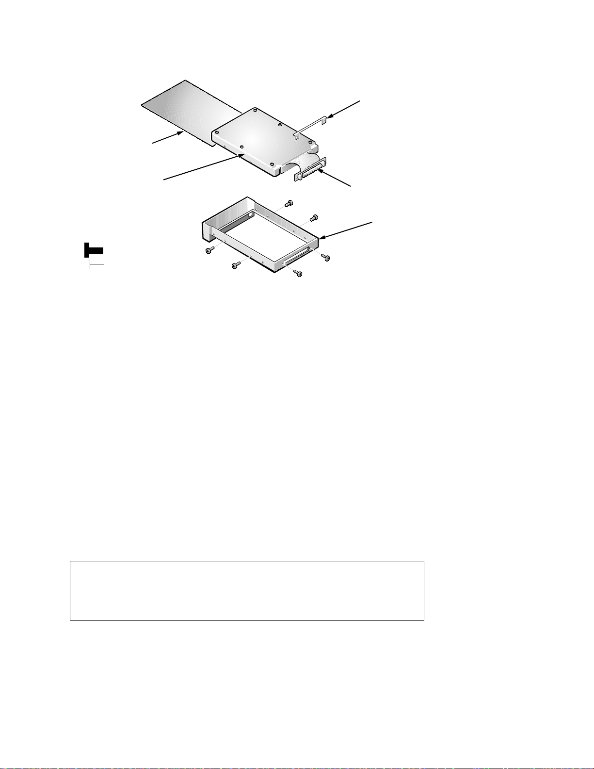
H
ard-Disk Drive
insulator
cable protector
hard-disk drive
(screws E1–E6
are 5 mm)
5 mm
E1
E2
E6
E5
E3
flex-cable
connector
carrier
E4
Figure 4-16. Hard-Dis k Drive Disassembly
The hard-disk drive resides in an EMI insulator in a carrier that mounts in the
computer’s hard-disk drive compartment on the left side of the computer. Six
screws secure the drive inside the carrier. To disassemble the hard-disk drive
from the carrier and the insulator, follow these steps:
1. Remove the hard-disk drive assembly from the computer.
See step 7 of “Precautionary Measures” found earlier in this chapter.
2. Place the hard-disk drive assembly in a hard-disk drive fixture, and remove
hard-disk drive screws E1 through E6.
3. Remove the cable protector.
4. Remove the hard-disk drive from the fixture, and then remove the hard-disk
drive and insulator from the carrier.
Turn the carrier over with one hand and let the drive and insulator fall out of
the carrier into your other hand. Y ou may have to thread the cable out of the
slot for it in the carrier.
CAUTION: In step 5, use a small flat-blade screwdriver to disconnect
the flex-cable connector. Do not handle the flex cable too roughly or you
could accidently disconnect the cable from the connector card rather than
the drive.
5. Remove the hard-disk drive from the insulator.
Carefully pry the flex-cable connector away from the hard-disk drive inter-
face connector on the back of the drive.
Removing and Replacing Parts 4-29
Page 66
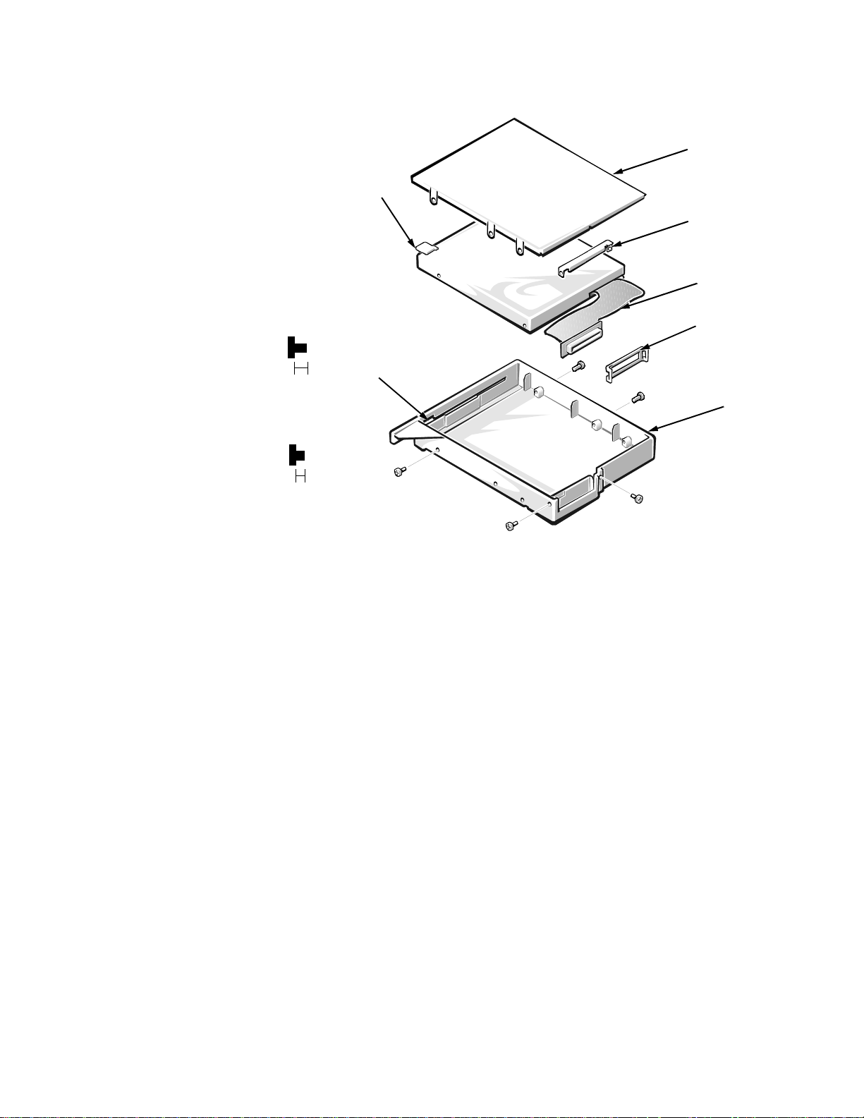
D
iskette Drive
eject button
shield
cable lock
flex cable
(screws FD1–FD3
are 3 mm)
3 mm
(screws FD4 and
FD5 are 2.5 mm)
2.5 mm
eject button
recess
FD2
FD3
FD1
FD4
FD5
cable support
carrier
Figure 4-17. Diskette Drive Disassembly
The diskette drive resides in a carrier that slides into the options drive bay on
the right side of the computer. To remove the diskette drive from the carrier,
follow these steps:
1. Remove diskette drive screws FD1, FD2, and FD3.
2. Remove the protective shield.
3. Remove diskette drive screws FD4 and FD5.
4. Lift the cable lock from the flex cable.
5. Lift the diskette drive from the carrier.
Lift the back of the drive first, to free the eject button from the eject button
access.
6. Remove the cable support from the flex-cable connector.
4-30 Dell Inspiron 3000 Series Service Manual
Page 67
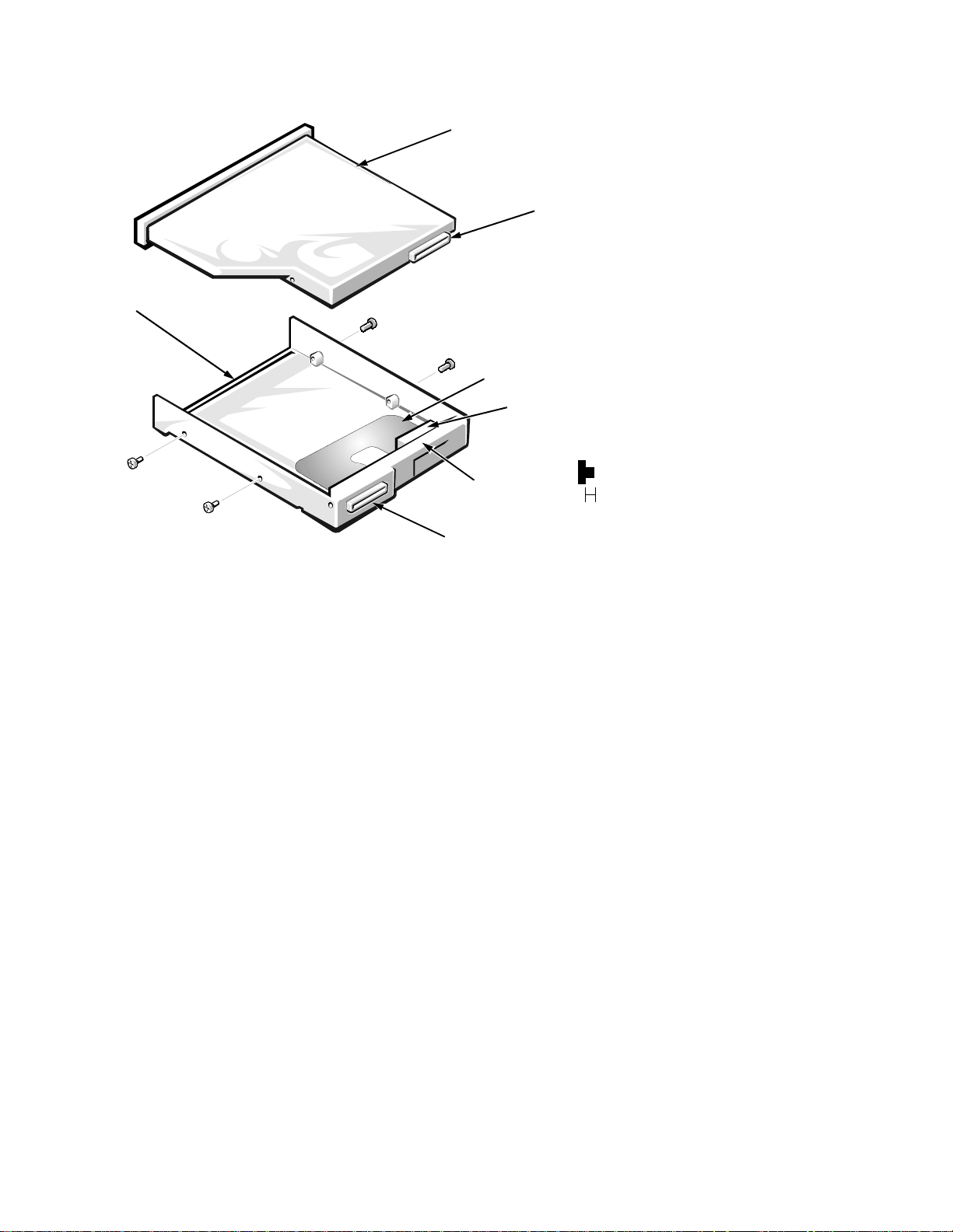
C
D-ROM/DVD-ROM Drive
CD-ROM/DVD-ROM drive
drive connector
carrier
CD4
CD3
CD1
CD2
flex cable
internal connector
(screws CD1–CD4
are 2 mm)
lip
2 mm
external connector
Figure 4-18. CD-ROM/DVD-ROM Drive Disassembly
The CD-ROM drive or DVD-ROM drive resides in a carrier that slides into the
options drive bay on the right side of the computer. To disassemble the CDROM drive or DVD-ROM drive assembly, follow these steps:
1. Remove screws CD1, CD2, CD3, and CD4 that hold the CD-ROM drive or
DVD-ROM drive to the carrier.
2. Disconnect the internal connector on the flex cable from the drive
connector.
3. Lift the CD-ROM drive or DVD-ROM drive out of the carrier.
When reinstalling the CD-ROM drive or DVD-ROM drive in the carrier, make
sure the rubber cushion behind the internal connector fits under the lip.
Removing and Replacing Parts 4-31
Page 68

G
y
y
eneral Disassembly
.
General disassembly procedures assume that the following removal procedures
(described at the beginning of this chapter) have been accomplished:
•
AC adapter
•
Port replicator
•
PC Card
•
Hard-disk drive
•
Memory (module cover and modules)
•
Options bay device
•
Main batter
Preparation
There are many screws of various sizes. To assist in keeping track of the
screws, use a tackle or pill box as a storage device. A location template (see
Figure 4-19) is useful as a label for the storage device for the screws. The information in parentheses ( ) denotes the screw name(s) called out in the figures. Be
careful not to scratch the computer plastic case by allowing the screws to get
between the disassembly surface and the plastic case. Also, to prevent case
scratches, a soft padded work surface is suggested.
HDD ba
(HD1, HD2, B4);
battery bay (B5);
HD drive (E1–E6)
upper case
beside
microphone (CS3,
CS4)
standoffs
(ST1–ST3);
PC Card cage
(P1–P4)
diskette drive
(FD1–FD5);
CD-ROM drive
(CD1–CD4)
upper case at interior opening
(CS5, CS6)
front bezel
(F1–F4 on
12.1”, F5 and F6
on 13.3”)
keyboard
(K1, K2);
heat sink
(HS1–HS3)
IR PWA (IR1);
HDD heat sink
(HT1–HT6)
LCD panel
(LC1–LC4 on
12.1”,
LC5–LC8 on
13.3”)
status
display (SD1);
13.3” LCD
ground (G1);
12.1” LCD
ground (G1,
G2)
touch pad (H7);
speakers
(S1, S2)
12.1” LCD
hinges
(H6, H7, H9,
and H10)
LCD hinge
(H1–H4);
bottom of base
assembly
(B1–B3)
LVDS (G2);
USB (U1)
12.1” LCD
bracket
(H5, H8)
upper case
below LCD
(CS1, CS2)
main board
(M1–M3);
I/O panel
(ST4–ST11)
13.3” LCD
hinges
(H12–H15);
13.3” LCD
bracket
(BR1–BR3)
Figure 4-19. Location Template
CAUTION: During the following removal and replacement procedures,
you will see Kapton tape in many places on the computer. When reinstalling or replacing parts, be sure to replace the Kapton tape correctly
to retain the electrical protection and noise reduction the tape provides.
4-32 Dell Inspiron 3000 Series Service Manual
Page 69
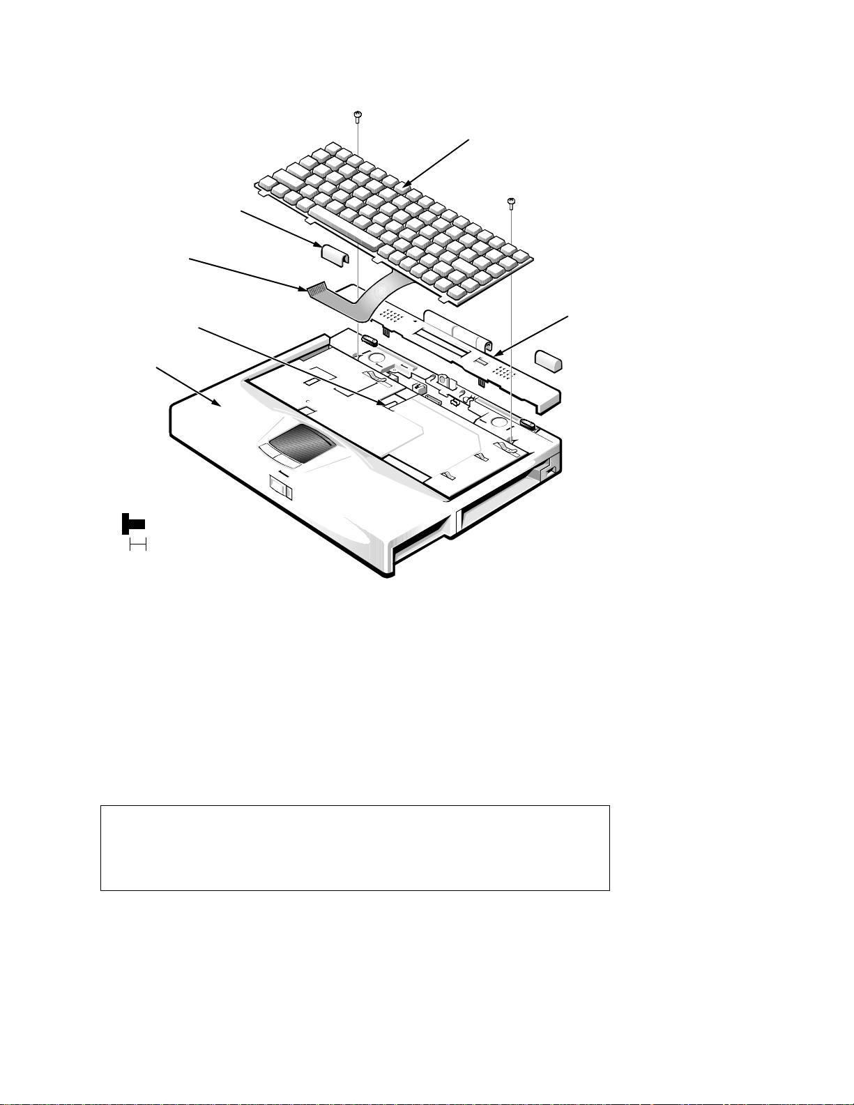
K
eyboard
K1
keyboard
hinge covers (2)
keyboard cable
ZIF connector
palmrest
(screws K1 and
K2 are 4 mm)
4 mm
K2
connector
cover
Figure 4-20. Keyboard Removal
To remove the keyboard, follow these steps:
1. Remove the hinge covers.
If the hinge covers are tight, use a plastic wedge or scribe to loosen them.
2. Remove the connector cover.
Start from the right side and gently pry the connector cover from the
computer.
CAUTION: When reinstalling the connector cover, be sure the routing of the I/R cable (see Figure 4-22) is correct. If the wires of the I/R
cable are not replaced correctly, in relation to the tabs of the c onnec tor cover, future removal of the cover may not be possible.
Removing and Replacing Parts 4-33
Page 70

3. Remove the keyboard screws K1 and K2.
4. Lift up the keyboard from the palmrest.
Pull forward at the back of the keyboard to release the edge of the keyboard
from the palmrest assembly.
5. Disconnect the keyboard cable from the ZIF connector.
Use a small flat-blade screwdriver or scribe to release the ZIF connector
securing the keyboard cable.
CAUTION: Lift away the cable only after the ZIF connector is
opened (see “ZIF Connectors” found earlier in this chapter). Pulling
the cable from the connector damages the conductive coating on the
end of the cable.
6. Remove the keyboard from the palmrest.
4-34 Dell Inspiron 3000 Series Service Manual
Page 71
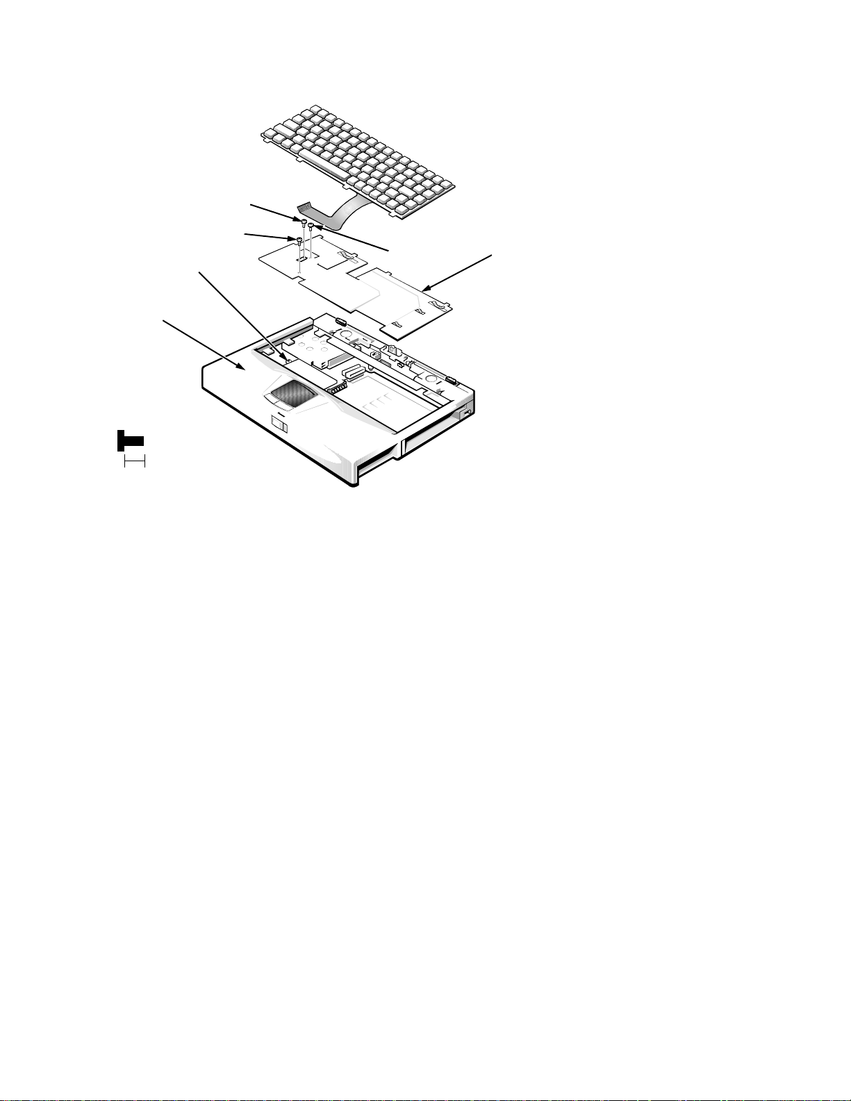
H
eat Sink
fan
connector
palmrest
assembly
(screws HS1–HS3
are 5 mm)
HS3
HS1
HS2
heat sink
5 mm
Figure 4-21. Heat Sink Removal
To remove the heat sink, follow these steps:
1. Remove the keyboard.
2. Remove black chromate panhead screws HS1, HS2, and HS3.
The heat sink will come free except for the fan cable. Push back and lift up
on the heat sink to access the fan cable.
3. Remove the fan cable.
The fan cable is beneath the heat sink on the left side. Use a plastic scribe or
flat-blade screwdriver, if necessary.
4. Remove the heat sink from the palmrest assembly.
Removing and Replacing Parts 4-35
Page 72
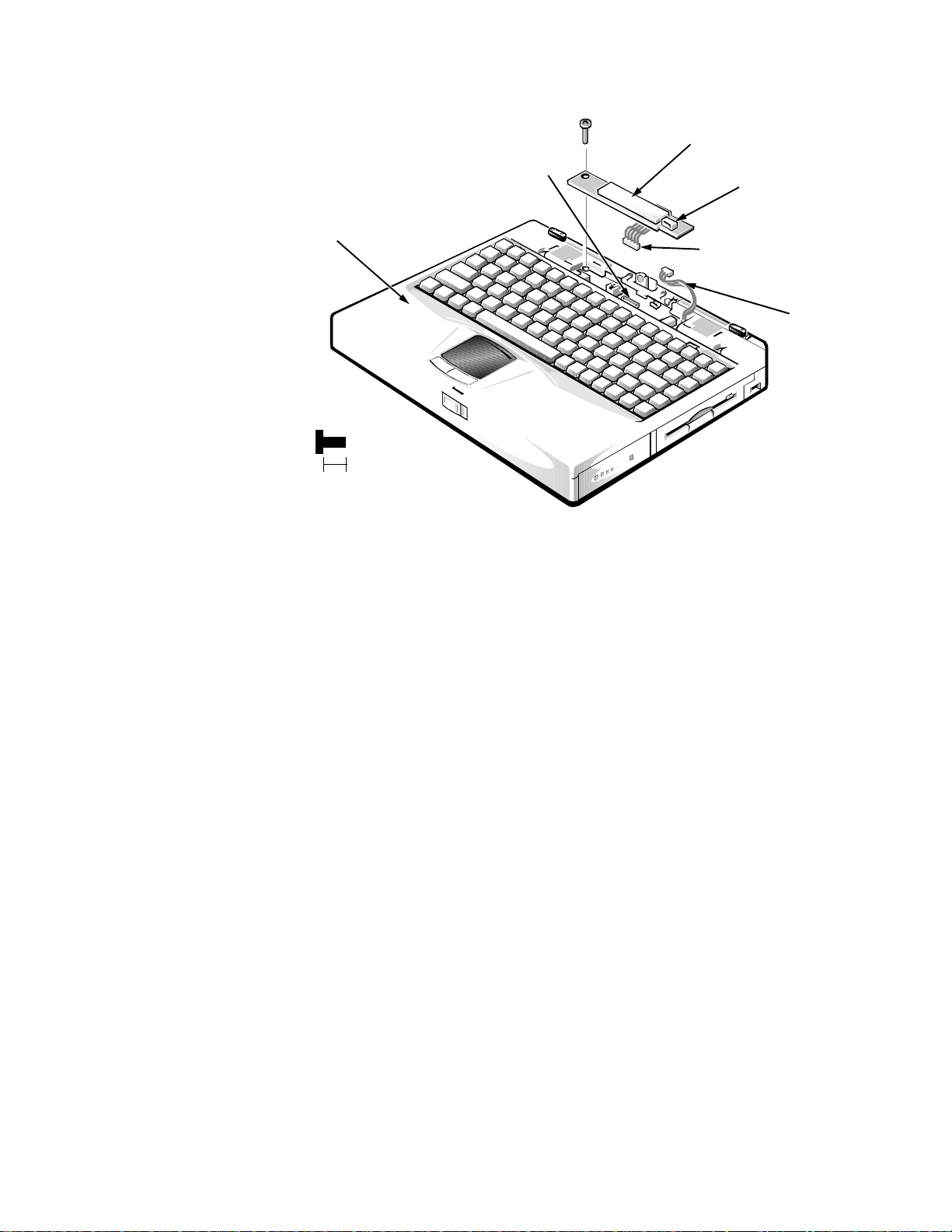
S
(screw SD1 is 5 mm)
5 mm
SD1
status display panel
status display panel
connector
I/R cable
palmrest
assembly
connector P3
connector JP5
tatus Display Panel
Figure 4-22. Status Display Panel Removal
To remove the status display panel, follow these steps:
1. Remove the hinge covers and connector cover.
See “Keyboard” found earlier in this chapter.
2. Remove status display panel screw SD1.
3. Remove the status display panel.
The status display panel has two connectors.
4. Disconnect the status display panel connector from connector JP5 on the
main board.
5. Disconnect the I/R cable from connector P3 on the status display panel.
6. Remove the status display panel from the palmrest assembly.
When reinstalling the status display panel, see the first Caution for “Keyboard”
found earlier in this chapter.
4-36 Dell Inspiron 3000 Series Service Manual
Page 73
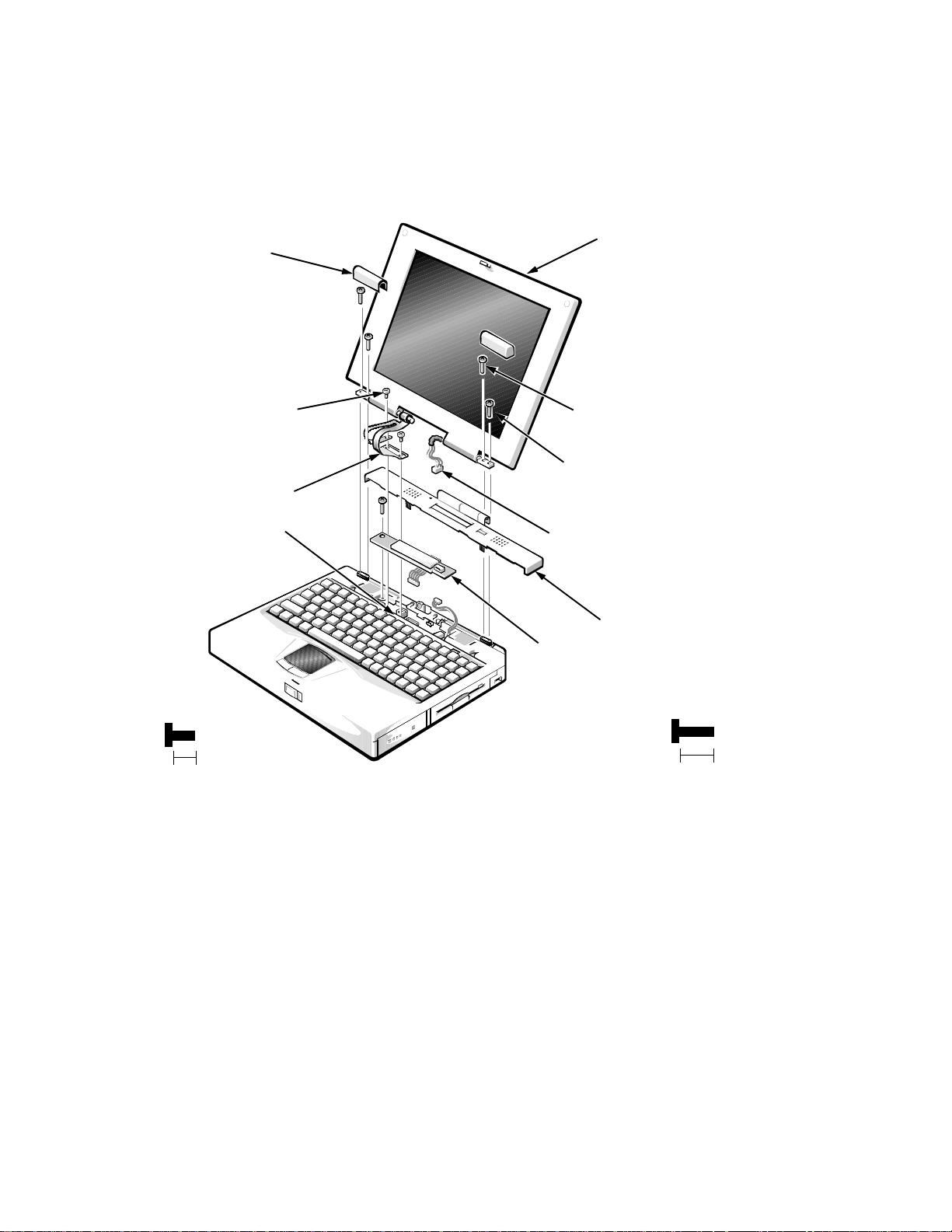
L
CD Assembly
The LCD assembly consists of the display assembly and its related components.
This section describes how to remove either the 12.1-inch or 13.3-inch LCD
assembly . Later sections in t his chapter provide removal and replacement procedures for the components of the LCD assembly.
hinge covers (2)
G1
LCD flex cable
connectors JP8 or JP1
LCD assembly
H1
H2
H3
G2
H4
inverter cable
connector cover
status display panel
(screws G1 and
G2 are 5 mm)
5 mm
NOTE: This is a figure of a 12.1-inch LCD assembly. The 13.3-inch LCD
assembly has an LCD wiring harness instead of an LCD flex cable.
Figure 4-23. LCD Assembly Removal
To remove the LCD assembly, follow these steps:
1. Remove the hinge covers and the connector cover.
See “Keyboard” found earlier in this chapter.
2. Remove the status display panel.
3. Disconnect the inverter cable.
The inverter cable is a cable harness on the right side of the LCD assembly.
(screws H1–H4
are 8 mm)
8 mm
Removing and Replacing Parts 4-37
Page 74

4. For a 12.1-inch display, remove cable connector screws G1 and G2. For a
13.3-inch display, remove only cable connector screw G1.
On 12.1-inch displays, screw G1 holds the LCD cable ground in place. G1
has a square washer. On 13.3-inch displays, screw G1 holds the left side of
the LVDS board (see Figure 4-32) in place.
5. For a 12.1-inch display, disconnect the LCD flex cable from connector JP8
on the main board. For a 13.3-inch display, disconnect the LCD cable harness from connector JP1 on the LVDS board (see Figure 4-32).
6. Close the display and remove hinge screws H1, H2, H3, and H4.
7. Remove the LCD assembly from the computer.
4-38 Dell Inspiron 3000 Series Service Manual
Page 75
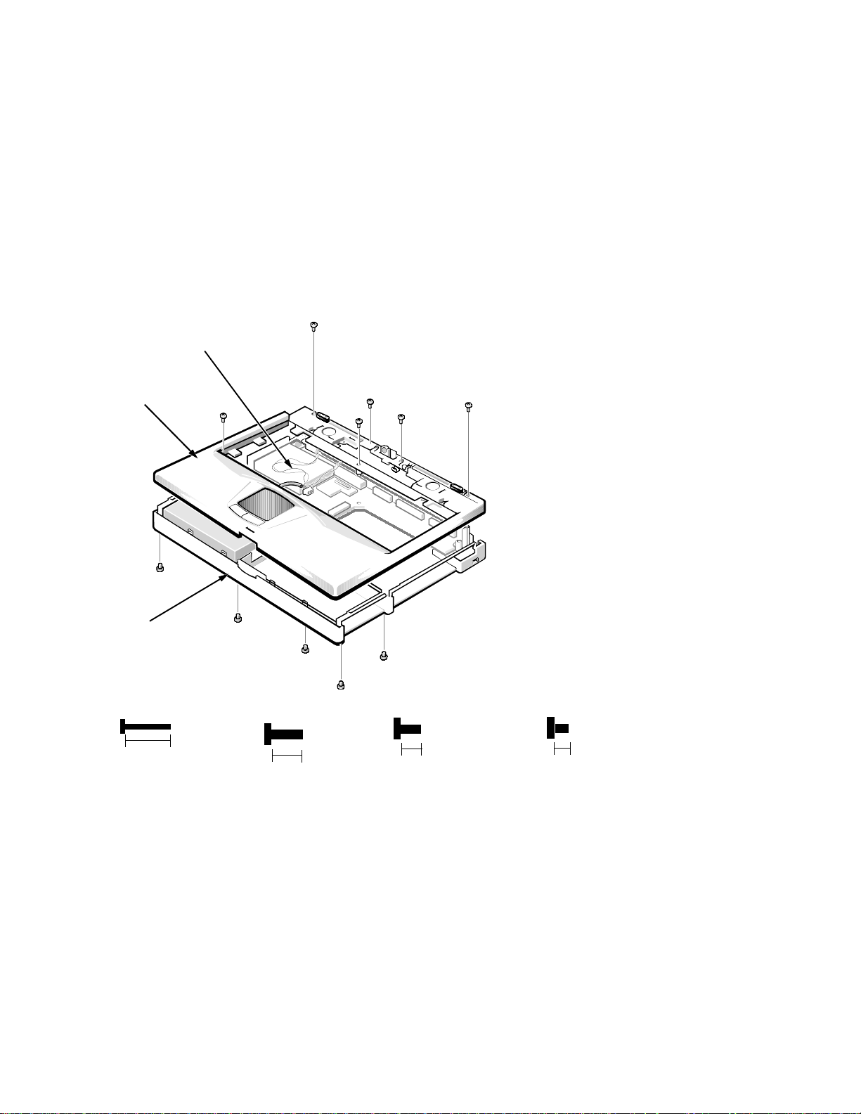
P
almrest Assembly
The palmrest assembly consists of the following components:
IR assembly
•
Left and right speaker assemblies
•
Hard-disk drive heat sink
•
Touch-pad assembly
•
The following subsections provide removal and replacement procedures for the
components of the palmrest assembly. These procedures assume that the keyboard assembly, heat sink, status display panel, and the LCD assembly have
been removed.
wiring
harness
palmrest
assembly
B4
base
assembly
(screws B1, B2, B3, CS5,
and CS6 are 12 mm)
CS6
B1
(screws CS1 and
CS2 are 8 mm)
B2
CS1
CS3
CS5
B5
(screws CS3, and
CS4 are 5 mm)
CS2
CS4
B3
(screws B4 and
B5 are 3 mm)
12 mm
8 mm
5 mm
Figure 4-24. Palmrest Assembly Removal
To remove the palmrest assembly, follow these steps:
1. Remove bottom screws B1, B2, B3, B4, and B5.
2. Remove case screws CS1 and CS2.
These screws are to the side of the hinges.
3. Remove case screws CS3 and CS4.
These screws are on either side of the microphone.
3 mm
Removing and Replacing Parts 4-39
Page 76

4. Remove case screws CS5 and CS6.
These screws are on the edge of the heat sink opening.
5. Disconnect the speaker wiring harness from connector JP16 (see
Figure 4-29).
This wiring harness also contains wiring for the touch pad and the touch pad
buttons.
6. Remove the palmrest assembly from the base assembly.
Start at the right rear of the computer and move forward around the com-
puter. Carefully lift the palmrest assembly up and pull it forward to release
the hidden tabs spaced around the sides and front.
When replacing the palmrest assembly, orient the assembly in its original position on the base assembly and press firmly near each tab until the palmrest
assembly snaps into place. Start at the front, to align those tabs first. Make sure
all the tabs are aligned.
4-40 Dell Inspiron 3000 Series Service Manual
Page 77
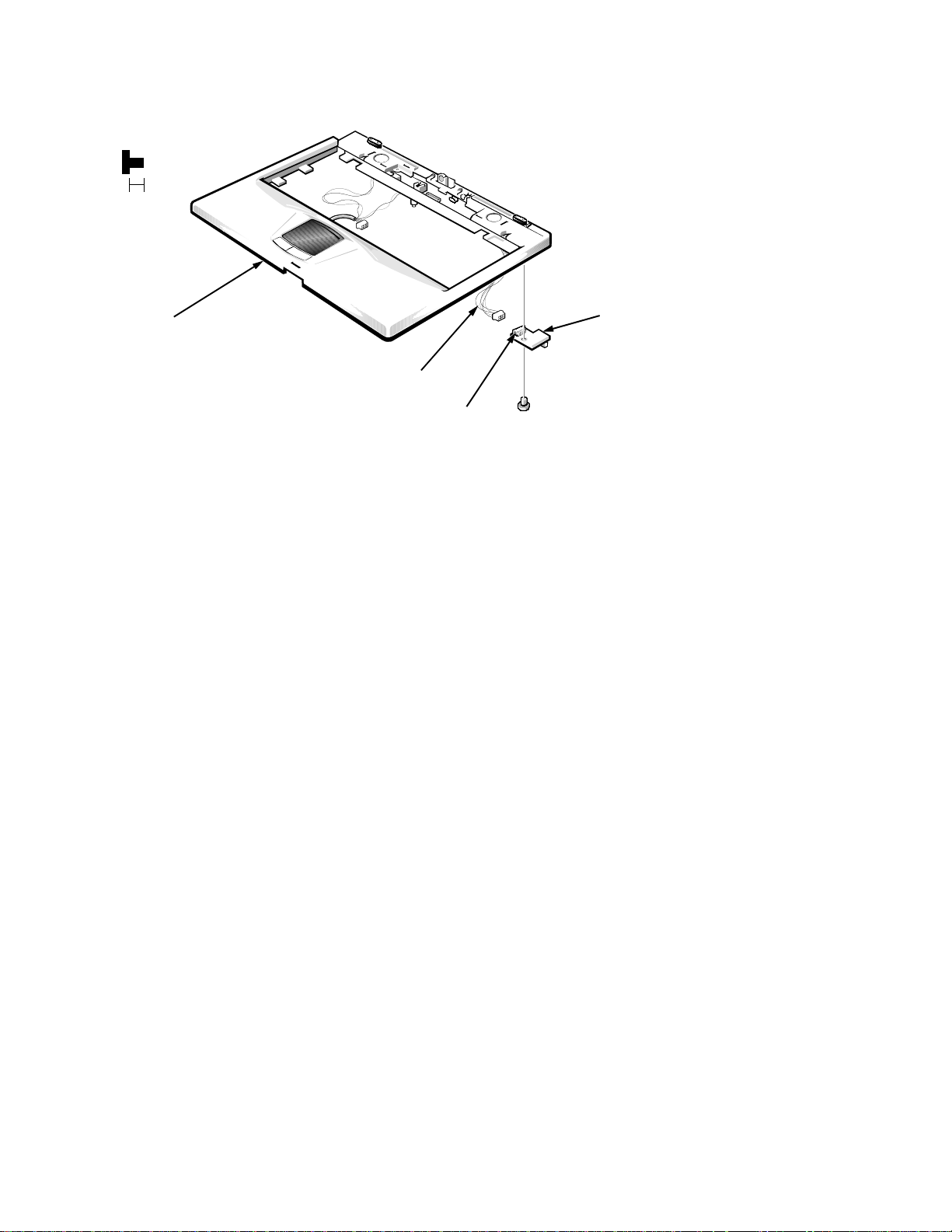
IR Board
(screw IR1
is 3 mm)
3 mm
palmrest
assembly
I/R board cable
connector JP1
IR1
Figure 4-25. IR Board Removal
To remove the IR board, follow these steps:
1. Remove the palmrest assembly.
2. Remove IR board screw IR1.
3. Disconnect the IR board cable from the IR board connector JP1.
4. Remove the IR board from the palmrest assembly.
I/R board
Removing and Replacing Parts 4-41
Page 78
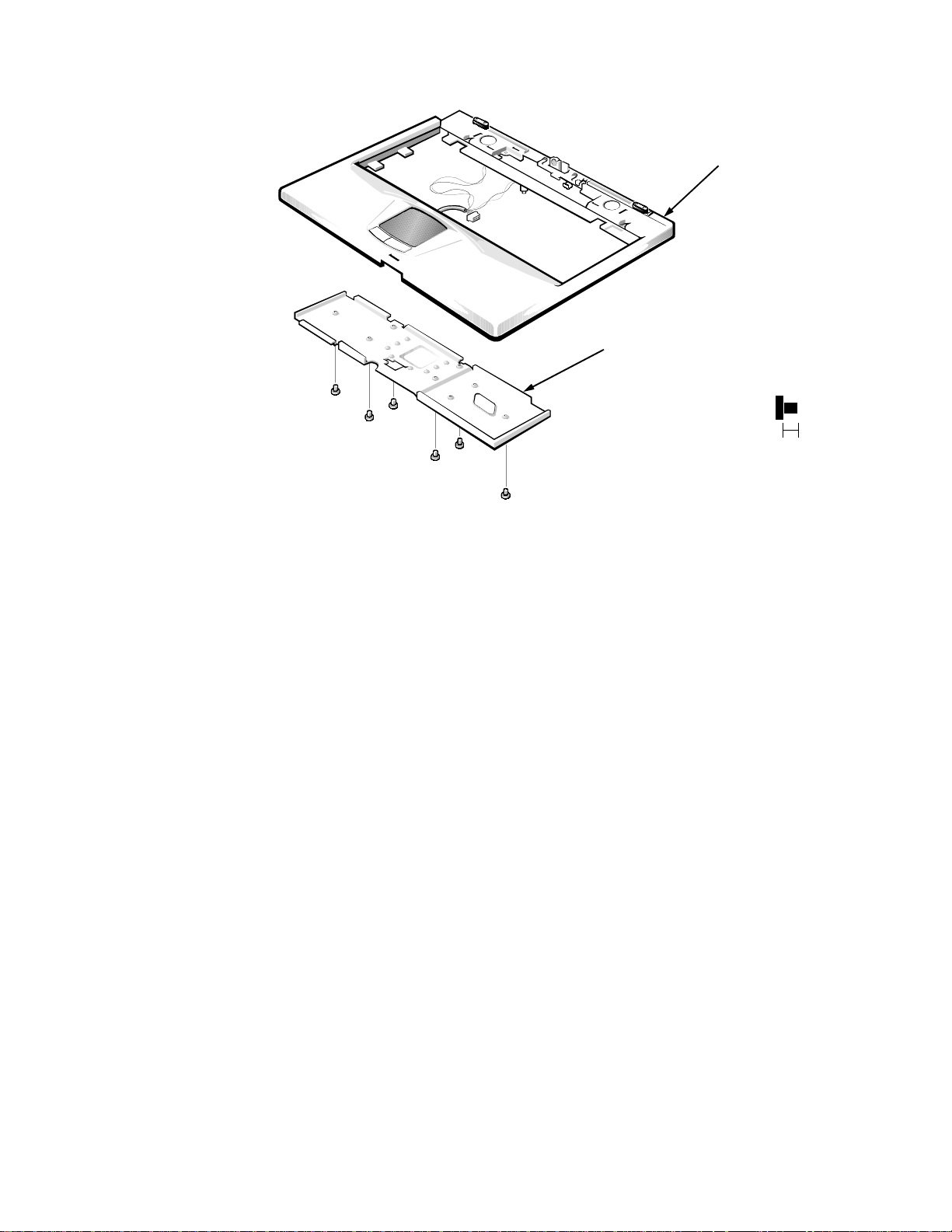
Hard-Disk Drive Heat Sink
palmrest assembly
HT1
HT2
HT3
HT4
HT5
HT6
hard-disk drive
heat sink
(screws HT1–HT6
are 3 mm)
3 mm
Figure 4-26. Hard-Disk Drive Heat Sink Removal
To remove the hard-disk drive heat sink, follow these steps:
1. Remove the palmrest assembly.
2. Remove hard-disk drive heat sink screws HT1 through HT6.
3. Remove the hard-disk drive heat sink from the palmrest assembly.
4-42 Dell Inspiron 3000 Series Service Manual
Page 79
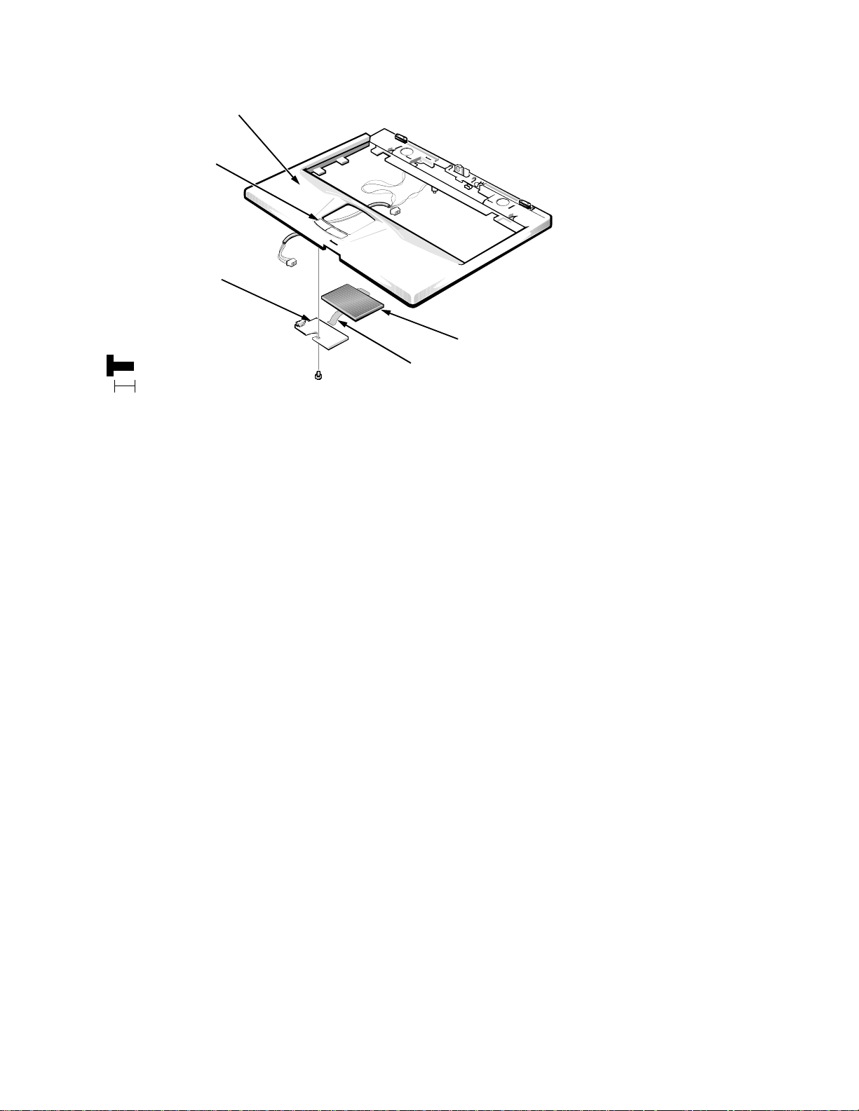
Touch-Pad Assembly
palmrest assembly
touch-pad buttons (2)
touch-pad
button board
(screw H7 is
5 mm)
touch-pad cable
H7
5 mm
Figure 4-27. Touch-Pad Assembly Removal
touch pad
To remove the touch-pad assembly, follow these steps:
1. Remove the palmrest assembly.
2. Remove the hard-disk drive heat sink.
3. Remove touch-pad button screw H7.
This screw holds the touch-pad button board in place.
4. Disconnect the touch-pad cable from touch-pad button connector JP1.
This is a ZIF connector on the touch-pad board. See “ZIF Connectors”
found earlier in this chapter.
5. Remove the touch pad from the computer.
The touch pad and touch-pad board are held in place by a flange.
6. Remove the touch-pad button board from the touch-pad buttons.
The board is held in place by two tabs. Rotate the board from under the tabs.
7. Disconnect the touch-pad cable from connector JP2 on the touch-pad button
board.
This is a pressure-fit cable. Reconnect the cable before reinstalling the
board.
8. Remove the touch-pad button board from the computer.
The touch-pad buttons are heat-staked into the palmrest assembly and are
not removable.
Removing and Replacing Parts 4-43
Page 80

Speakers
plastic housings (2)
speakers (2)
(screws S1 and
S2 are 3 mm)
3 mm
palmrest assembly
S2S1speaker wires
Figure 4-28. Speaker Removal
To remove the speaker, follow these steps:
1. Remove the palmrest assembly.
2. Remove the hard-disk drive heat sink.
3. Remove the touch-pad assembly.
4. Remove left speaker screw S1.
5. Remove the left speaker cover and speaker.
To replace the speaker, unsolder the wires.
6. Repeat steps 4 and 5 for the right speaker.
The right speaker screw is S2.
The touch-pad cable, microphone cable, microphone, speaker cables, and
speaker housing are joined in one wiring harness that plugs into the main
board connector JP1. The harness wires are held in place by nine tabs. When
reinstalling the harness, make sure it routes correctly beneath each of these
tabs.
4-44 Dell Inspiron 3000 Series Service Manual
Page 81

B
ase Assembly
The base assembly consists of the following components:
IR lens
•
Processor board
•
LVDS board (13.3-inch LCD only)
•
USB board
•
Main board
•
Audio bezel
•
Audio board
•
PC Card cage
•
Latch assembly
•
BIOS door
•
Rubber feet
•
The following subsections provide removal and replacement procedures for
most of the components of the base assembly. Procedures for the BIOS door,
rubber feet, and 13.3-inch bumpers are not shown because they are obvious.
The procedures in this subsection assume that the palmrest assembly and LCD
assembly have been removed.
Removing and Replacing Parts 4-45
Page 82
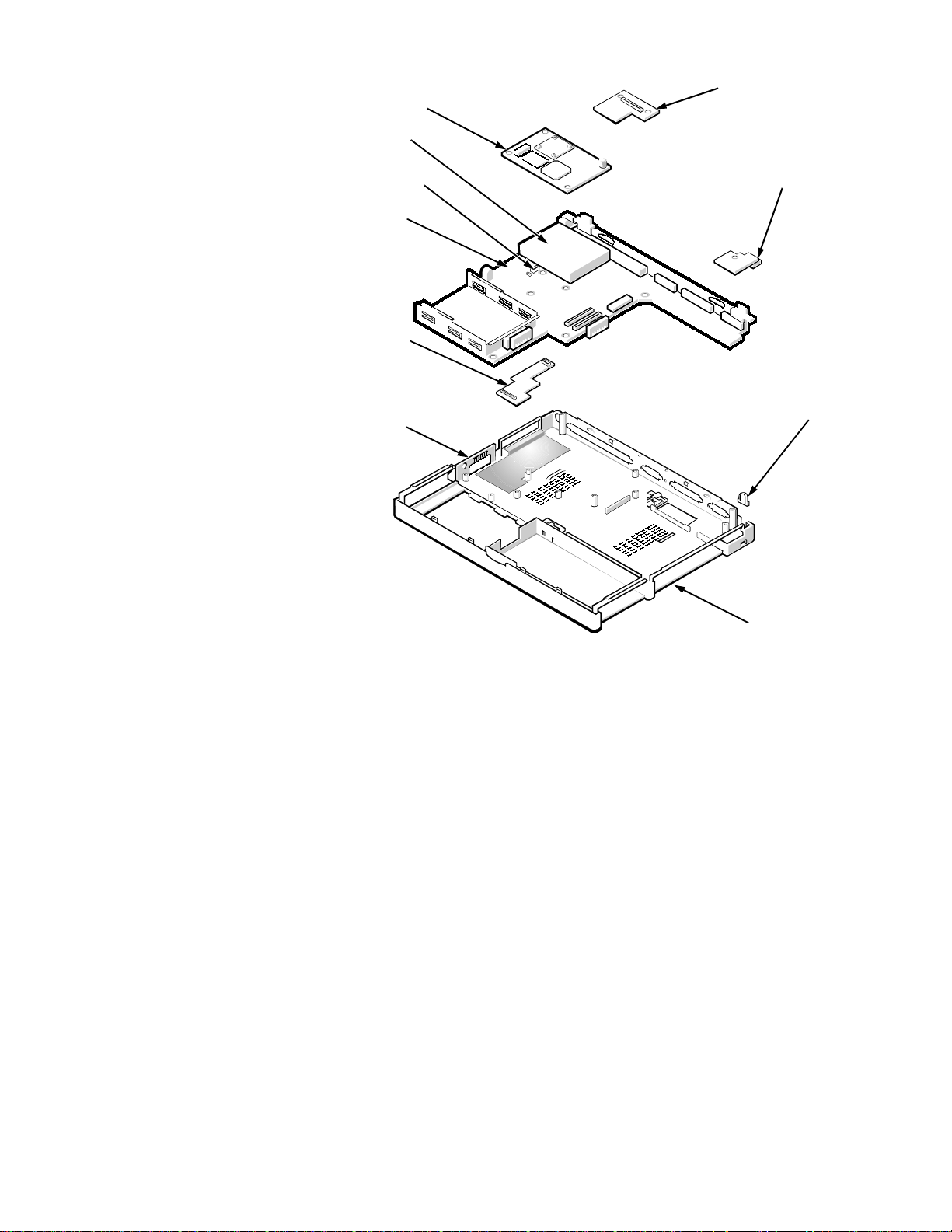
base assembly
main board
audio board
LVDS board
(13.3-inch LCD
only)
IR lens
processor board
audio bezel
PC Card cage
USB board
connector JP16
Figure 4-29. Base Assembly
4-46 Dell Inspiron 3000 Series Service Manual
Page 83

IR Lens
Figure 4-30. IR Lens Removal
IR lens
Remove the IR lens by gently pulling straight up on the lens with the fingers of
one hand.
Removing and Replacing Parts 4-47
Page 84

Processor Board
main board
processor board
connector JP18
connector JP19
rubber bumper
Figure 4-31. Processor Board Removal
Remove the processor board from the main board.
The processor board is held in place on the main board by connectors JP18 and
JP19. Using the fingers of one hand, gently remove the processor board from
the main board by pulling straight up. Do not rock the processor board to
remove it. This may damage the two connectors on the processor board or the
main board.
There is a rubber bumper on the upper right corner of the processor board. The
bumper assists in keeping the processor board in place. If you install a replacement processor board, be sure to apply a bumper in that corner of the processor
board. Also, there is heat-sink thermal pad on top of the micro processor and this
may need to be reinstalled.
When reinstalling the Inspiron M166ST, M200ST, M233ST, or M233XT processor board, press down on the white dot on top of the board. The white dot
indicates the best spot to apply pressure to seat the processor correctly on connectors JP18 and JP19. (White dot references on the Inspiron D233ST,
D233XT, and D266XT processor boards are not necessary.)
4-48 Dell Inspiron 3000 Series Service Manual
Page 85
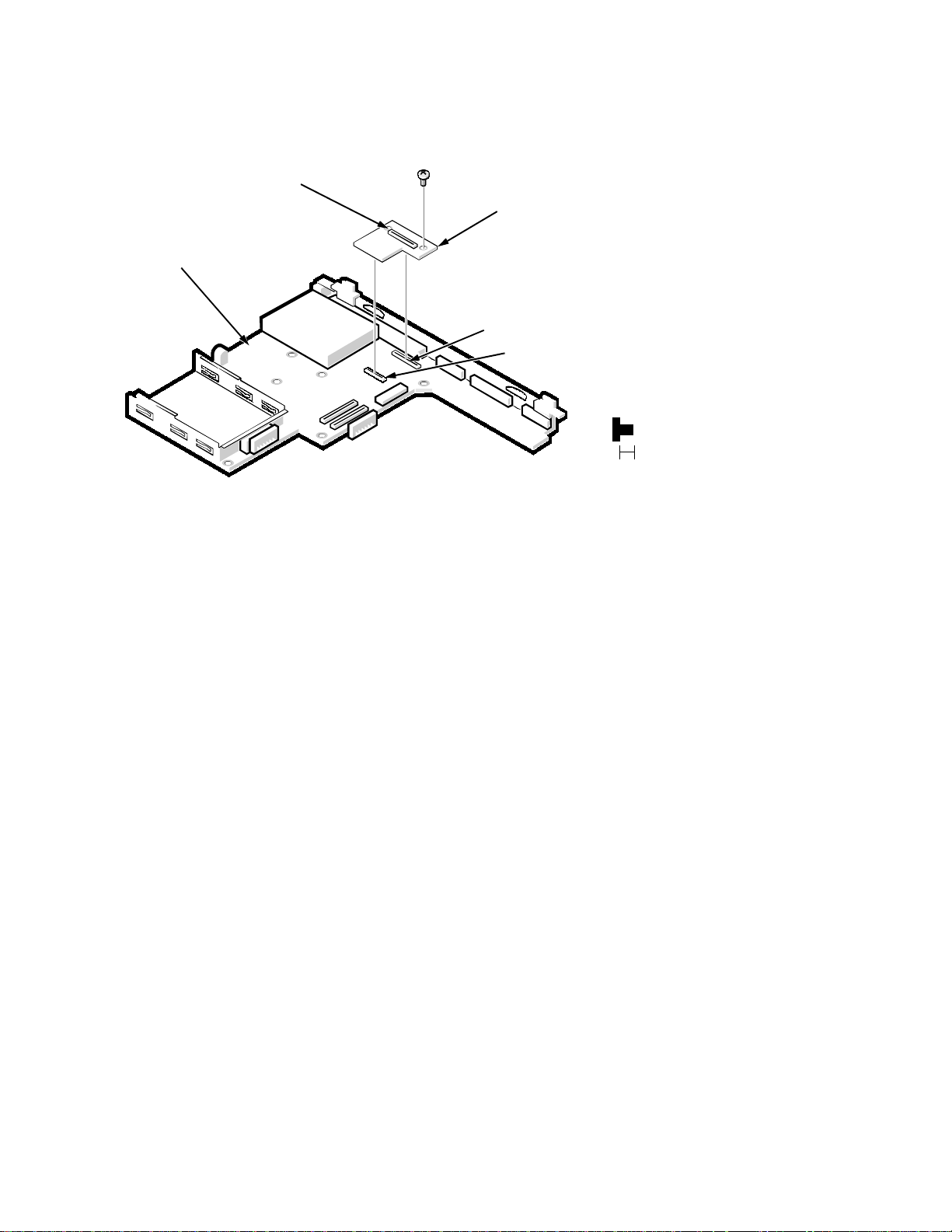
LV DS Board
The LVDS board is present on computers with a 13.3-inch LCD. If you have a
12.1-inch LCD, skip this subsection.
connector JP1
main board
G2
LVDS board
connector JP8
connector JP12
Figure 4-32. LVDS Board Removal
To remove the LVDS board, follow these steps:
1. Remove LVDS board screw G2.
This is the other screw that you left in place when you removed the
13.3-inch LCD cable harness from connector JP1 on the LVDS board.
(screw G2
is 3 mm)
3 mm
2. Remove the LVDS board from the main board.
The LVDS board is held in place on the main board by connectors JP8 and
JP12.
3. Remove the LVDS board from the computer.
Removing and Replacing Parts 4-49
Page 86
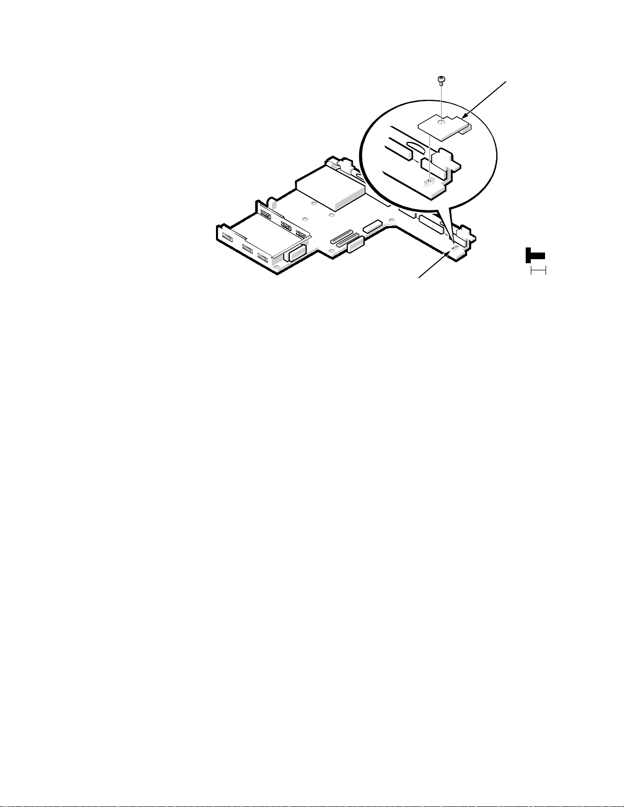
USB Board
(screw U1
is 5 mm)
5 mm
U1
connector JP9
USB board
Figure 4-33. USB Board Removal
To remove the USB board, follow these steps:
1. Remove USB board screw U1.
2. Disconnect the USB board from connector JP9 on the main board.
With the fingers of one hand, gently pull the USB board straight up about
-inch to free it from connector JP9. Then turn the board slightly to the
1/4
right to remove it from the corner of the main board and the base assembly.
4-50 Dell Inspiron 3000 Series Service Manual
Page 87
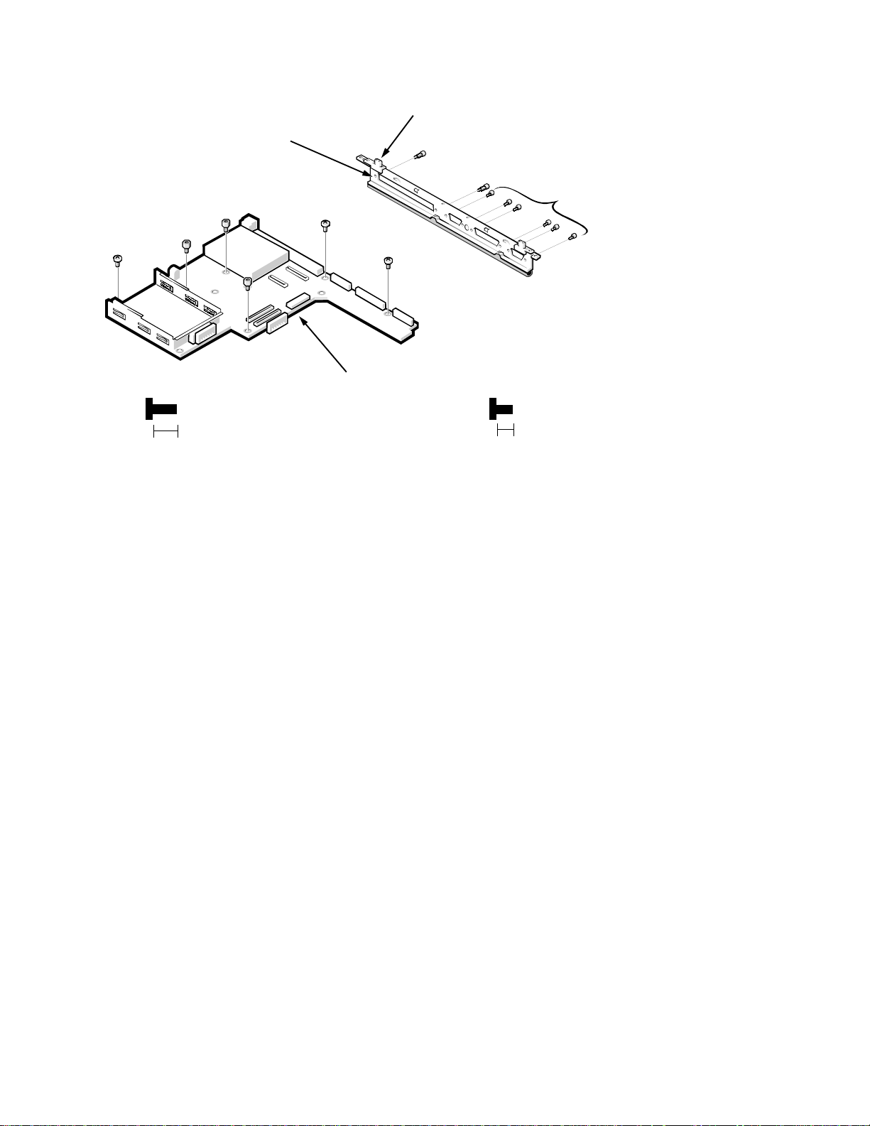
Main Board
hinge blocks (2)
I/O panel bracket
ST1
ST2
M3
ST3
(standoffs ST1, ST2, ST3,
ST10, and ST11 are 6 mm)
6 mm
M1
main board
Figure 4-34. Main Board Removal
To remove the main board, follow these steps:
ST11
ST10
ST4–ST9
M2
(screws M1, M2, M3,
and ST4–ST9 are 5 mm)
5 mm
1. Remove the processor board.
2. If one is installed, remove the LVDS board. Otherwise, go to step 3.
3. Remove the USB board.
4. Remove main board screws M1, M2, and M3.
5. Remove standoff nuts ST1, ST2, and ST3.
6. Remove the main board from the base assembly.
Lift the end of the board nearest the front of the computer, and pull the
board up and out of the computer.
Remove the I/O panel bracket only if you have to replace it. The I/O panel
bracket can be removed from the main board by removing standoff nuts ST4
through ST11. Use a 5-mm nut driver t o remove st andof f nut s S T4-ST9 and
a 6-mm nut driver for ST10 and ST11.
If the threads on the two hinge blocks are damaged, the I/O panel bracket
will have to be replaced.
Removing and Replacing Parts 4-51
Page 88
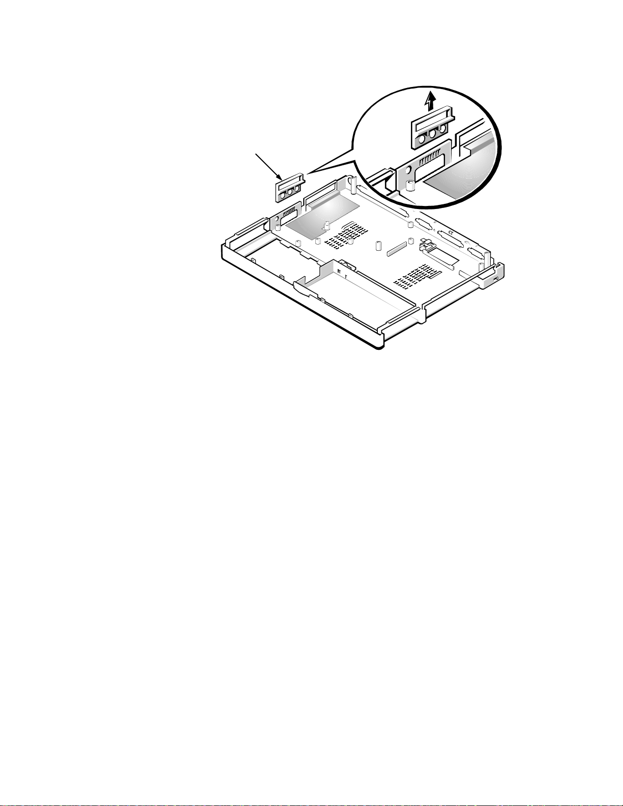
Audio Bezel
audio bezel
Figure 4-35. Audio Bezel Removal
Remove the audio bezel by gently pulling it from the three audio jacks on the
left side of the main board. This bezel usually drops out when the main board is
removed from the computer.
4-52 Dell Inspiron 3000 Series Service Manual
Page 89
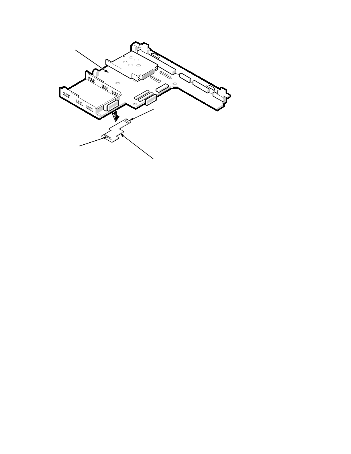
Audio Board
main board
connector JP1
audio board
Figure 4-36. Audio Board Removal
To remove the audio board, follow these steps:
connector JP2
1. Remove the main board.
2. Remove the audio board from the bottom of the main board.
The audio board is held in place by two connectors on the main board (JP26
and JP22) and two connectors on the audio board (JP1 and JP2). The connectors are different sized to ensure correct placement when reinstalling the
audio board.
Ensure that you reinstall the audio board when you reinstall the main board.
Make sure there are two rubber bumpers installed on the side of the audio board
next to the back cover.
Removing and Replacing Parts 4-53
Page 90
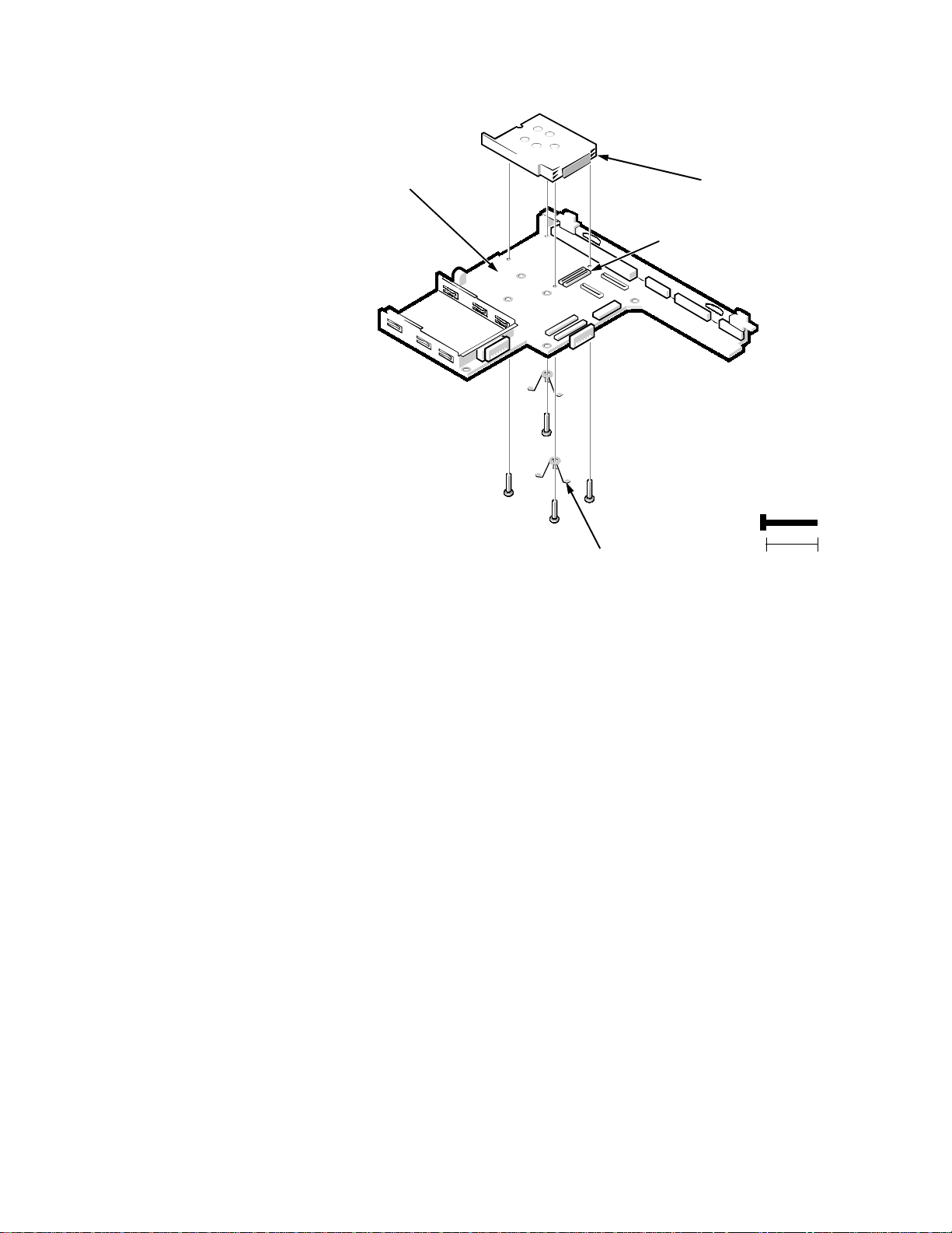
PC Card Cage
PC Card cage
(top and bottom)
(screws P1–P4
are 13 mm)
P1
13 mm
main board
P2P3P4
ground springs (2)
connector JP11
Figure 4-37. PC Card Cage Removal
To remove the PC card cage, follow these steps:
1. Remove the main board.
Use a support for the main board to prevent the board from flexing when the
card cage screws are removed
2. Remove PC Card cage screws P1, P2, P3, and P4.
Screws P2 and P4 have ground springs attached. There are plastic insulators
on the main board, below the ground springs.
3. Remove the top of the card cage.
Disconnect the top from connector JP11 on the main board.
4. Remove the bottom of the card cage.
Disconnect the bottom from the connector next to JP11 on the main board.
A mylar covering is attached to the main boa rd below the bottom of th e card
cage.
Replace the PC Card cage if it is damaged.
4-54 Dell Inspiron 3000 Series Service Manual
Page 91
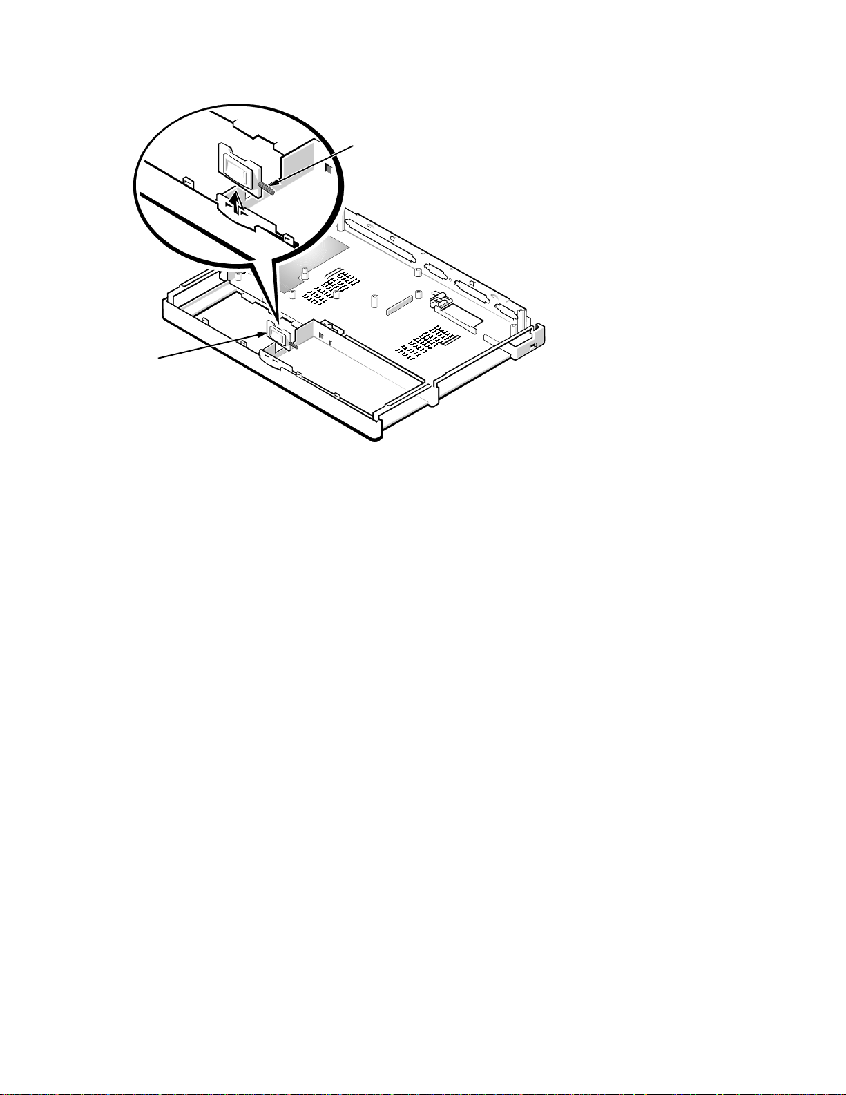
Latch Assembly
spring
latch
Figure 4-38. Latch Assembly Removal
To remove the latch assembly, follow these steps:
1. Remove the latch assembly from the base assembly.
Use the fingers of one hand and lift the assembly from its recess in the base
assembly. The latch assembly is held in place only by pressure.
2. Remove the spring from the latch.
Be careful not to lose the small spring that is part of the latch assembly.
Removing and Replacing Parts 4-55
Page 92
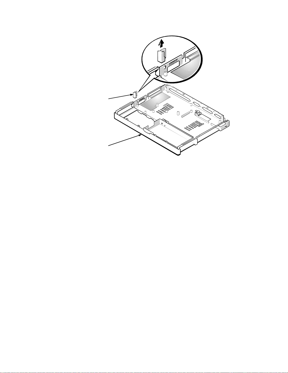
Kensington Lock Plate
Kensington
lock plate
base
assembly
Figure 4-39. Kensington Lock Plate Removal
Use a screwdriver to lift the Kensington lock plate from its recess in the base
assembly. The plate is held in place only by pressure.
4-56 Dell Inspiron 3000 Series Service Manual
Page 93

12.1
-Inch LCD Components
The 12.1-inch LCD assembly consists of the following components:
Front bezel
•
LCD panel
•
Inverter board and cable
•
Hinges
•
Bracket
•
Back cover
•
LCD flex cable
•
The following subsections provide removal and replacement procedures for
these components and assumes that the 12.1-inch LCD assembly has been
removed from the computer. See “LCD Assembly” found earlier in this chapter.
12.1-Inch LCD Front Bezel
upper bumpers (2)
F1
front bezel
bezel screw
covers (2)
F4
F3
(screws F1– F4
are 5 mm)
5 mm
Figure 4-40. 12.1-Inch LCD Front Bezel Removal
To remove the 12.1-inch LCD front bezel, follow these steps:
1. Remove the LCD assembly.
See “LCD Assembly” found earlier in this chapter.
F2
2. Use a dental pick to pry the front-bezel screw covers and upper bumpers out
of the screw holes in the bezel.
Removing and Replacing Parts 4-57
Page 94

3. Remove front bezel screws F1, F2, F3, and F4.
4. Separate the front bezel from the back cover.
With the bottom of the LCD assembly facing you (cables end), insert your
fingertips between the LCD panel and the front bezel. Start in the center of
the bezel and work out to the corners. With a peel-back-and-push motion,
separate the front bezel from the hidden tabs on the back cover. Do not put
pressure on the LCD panel with your knuckles; microscopic fractures in the
panel could result. Separate the bottom first and then proceed to each side,
leaving the top of the assembly until last. When the bottom and sides have
been released from the hidden tabs, proceed to the left corner. Lift the corner
of the front bezel out to the side, until the hidd en c orner tab is free d. Repe at
the procedure for the other corner, and lift up on the front bezel to release it
from the back cover. Lift the back cover over the latch.
When replacing the bezel, ensure that the LCD flex cable and the inverter cable
are routed correctly through the openings in the back cover and are not pinched.
4-58 Dell Inspiron 3000 Series Service Manual
Page 95
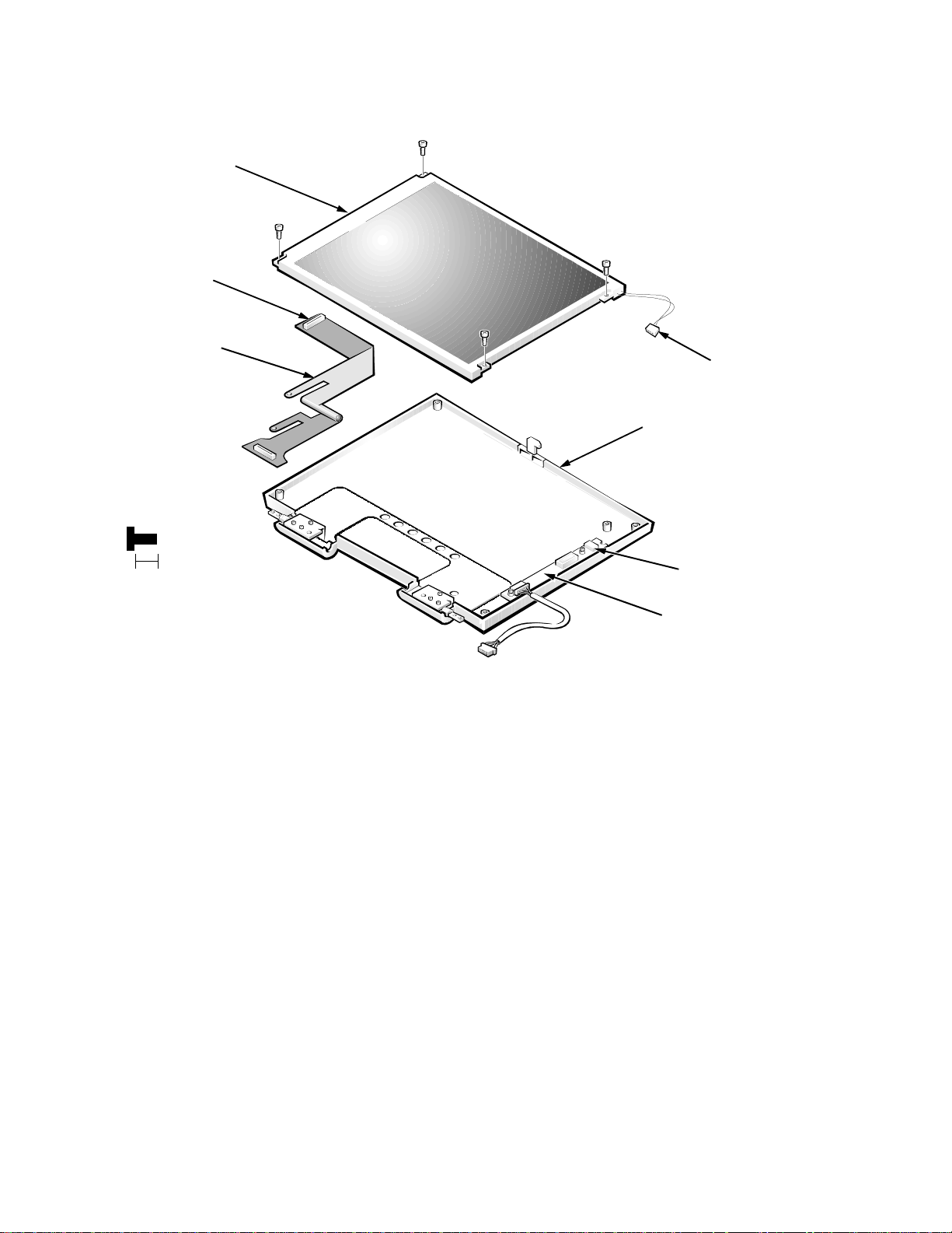
12.1-Inch LCD Panel
p
LCD panel
LC4
LC1
flex-cable
connector
LCD flex cable
(screws LC1–LC4
are 5 mm)
5 mm
.
Figure 4-41. 12.1-Inch LCD Panel Removal
LC3
LC2
LCD-toinverter
cable
back cover
connector
CN1
inverter board
To remove the 12.1-inch LCD panel, follow these steps:
1. Remove the front bezel.
See the previous subsection, “12.1-Inch LCD Front Bezel.”
2. Remove LCD panel screws LC1, LC2, LC3, and LC4.
3. Remove the LCD Panel.
NOTE: Be careful when removing any part of the LCD flex cable.
Lift up the LCD panel, and disconnect the LCD-to-inverter cable from connector CN1 at the top of the inverter board. Disconnect the LCD flex cable
from the flex-cable connector, J1, in the middle left side on the back of the
anel.
Removing and Replacing Parts 4-59
Page 96
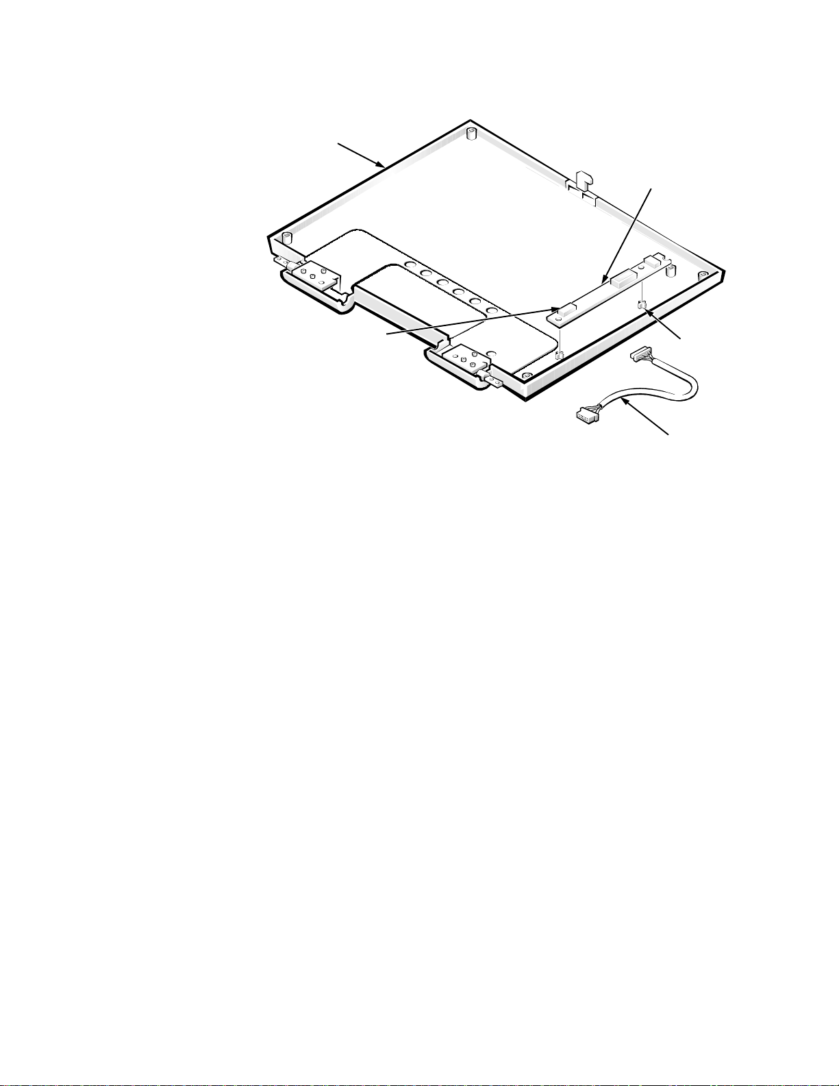
12.1-Inch LCD Inverter Board
inverter board
connector CN2
inverter cable
snaps (2)
back cover
.
Figure 4-42. 12.1-Inch Inverter Board Removal
To remove the 12.1-inch inverter board, follow these steps:
1. Remove the front bezel.
See “12.1-Inch LCD Front Bezel” found earlier in this section.
2. Remove the LCD panel.
See the previous subsection, “12.1-Inch LCD Panel.” You may not want to
remove this panel if you are replacing only the inverter board.
3. Disconnect the inverter cable from connector CN2 at the bottom of the
inverter board, and remove the cable.
4. Remove the inverter board from the back cover.
The inverter board is mounted on two plastic snaps. It is held in place by
these snaps and Kapton tape near the bottom of the board.
When replacing the inverter board, make sure you have the correct board. The
inverter board for a 12.1-inch IBM LCD assembly is different from the inverter
board for a 12.1-inch Samsung LCD assembly.
4-60 Dell Inspiron 3000 Series Service Manual
Page 97
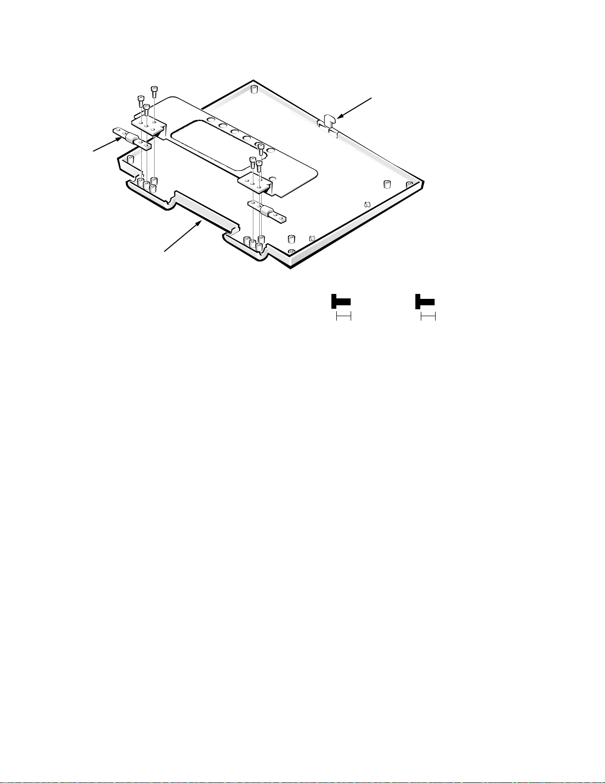
12.1-Inch LCD Hinges
H6
hinges (2)
back cover
H5
H7
H8
H9
H10
Figure 4-43. 12.1-Inch LCD Hinges Removal
(screws H6, H7, H9,
and H10 are 5 mm)
5 mm
latch
(screws H5 and
H8 are 5 mm)
5 mm
To remove the 12.1-inch LCD hinges, follow these steps:
1. Remove the front bezel.
See “12.1-Inch LCD Front Bezel” found earlier in this section.
2. Place the back cover down on a work surface.
3. Remove the hinge screws H6, H7, H9, and H10.
You may need to loosen screws H5 and H8 to free the hinges.
4. Remove the hinges from the back cover.
The bracket does not have to be taken of f to remove the hi nges. The bracket
in Figure 4-43 is shown removed to assist understanding.
The hinges for the 12.1-inch LCD assembly are anodized and
interchangeable.
Removing and Replacing Parts 4-61
Page 98
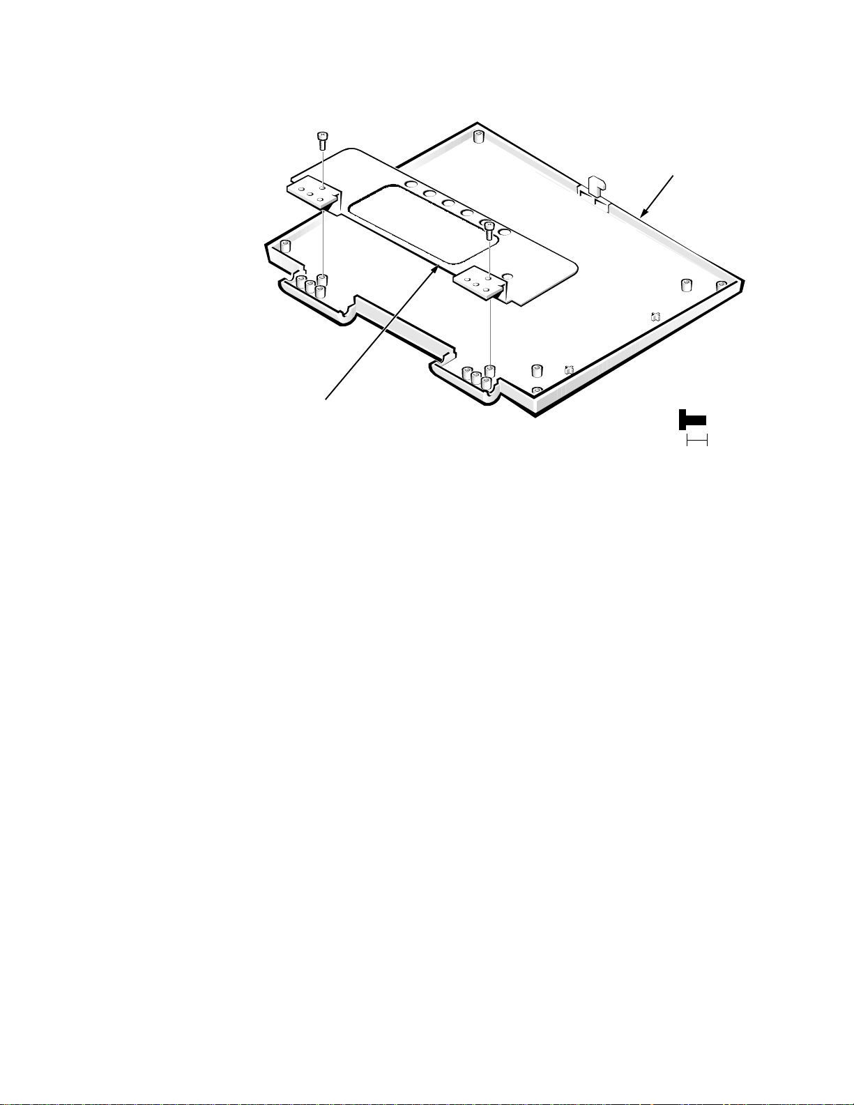
12.1-Inch LCD Bracket
back cover
bracket
(screws H5 and
H8 are 5 mm)
5 mm
H5
H8
Figure 4-44. 12.1-Inch LCD Bracket Removal
To remove the 12.1-inch LCD bracket, follow these steps:
1. Remove the front bezel.
See “12.1-Inch LCD Front Bezel” found earlier in this section.
2. Remove the LCD panel.
See “12.1-Inch LCD Panel” found earlier in this section.
3. Remove the hinges.
See the previous subsection, “12.1-Inch LCD Hinges.”
4. Remove bracket screws H5 and H8.
5. Remove the bracket from the back cover.
With your fingers, slide the bracket toward the top of the cover and lift the
bracket off the back cover. There are two clips, one near each hinge, that
hold the bracket in place.
4-62 Dell Inspiron 3000 Series Service Manual
Page 99
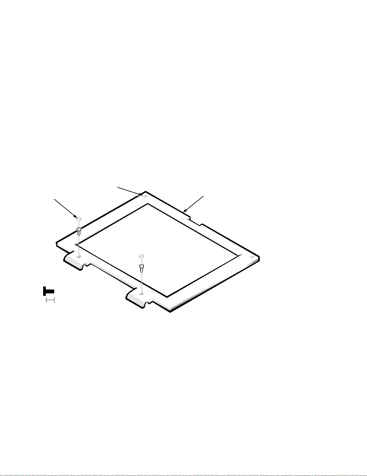
13.3
c
-Inch LCD Components
The 13.3-inch LCD assembly consists of the following components:
Front bezel
•
LCD panel
•
Inverter board and cable
•
Hinges
•
Bracket
•
Back cover
•
LCD wiring harness
•
The following procedures provide removal and replacement procedures for
these components, and assume that the 13.3-inch LCD assembly has been
removed from the computer. See “LCD Assembly” found earlier in this chapter.
13.3-Inch LCD Front Bezel
bumpers (2)
bezel screw
overs (2)
front bezel
F5
F6
(screws F5 and
F6 are 5 mm)
5 mm
Figure 4-45. 13.3-Inch LCD Front Bezel Removal
To remove the 13.3-inch LCD front bezel, follow these steps:
1. Remove the LCD assembly.
See “LCD Assembly” found earlier in this chapter.
2. Use a dental pick to pry the front-bezel screw covers out of the screw holes
in the bezel.
3. Remove front-bezel screws F5 and F6.
Removing and Replacing Parts 4-63
Page 100

4. Separate the front bezel from the back cover.
With the bottom of the LCD assembly facing you (cables end), insert your
fingertips between the LCD panel and the front bezel. Start in the center of
the bezel and work out to the corners. With a peel-back-and-push motion,
separate the front bezel from the hidden tabs on the back cover. Do not put
pressure on the LCD panel with your knuckles; microscopic fractures in the
panel could result. Separate the bottom first and then proceed to each side,
leaving the top of the assembly until last. When the bottom and sides have
been released from the hidden tabs, proceed to the left corner. Lift the corner
of the front bezel out to the side, until the hidd en c orner tab is free d. Repe at
the procedure for the other corner, and lift up on the front bezel to release it
from the back cover. Lift the back cover over the latch.
When replacing the front bezel, orient the bezel in its original position on the
assembly and press firmly near each tab until the bezel snaps into place. Ensure
that the LCD wiring harness and the inverter cable are routed correctly and are
not pinched.
4-64 Dell Inspiron 3000 Series Service Manual
 Loading...