

Page 1

Please check out our eBay auctions for more great
deals on Factory Service Manuals:
Page 2

®
'HOO/DWLWXGH
&3
5()(5(1&($1'
7528%/(6+227,1*
*8,'(
ZZZGHOOFRP
Page 3

Information in this document is subject to change without notice.
1994–1997 Dell Computer Corpor ation. All rights reserved.
Reproduction in any ma nner whatsoever without the wr it te n permission of Dell Compute r Corporation is strictly forbi dden.
Trademarks used in this text: Dell, the DELL logo, Latitude, and Dell Dimension are registered trad emarks, and DellW are is a registered service
mark of Dell Computer Corporation; Microsoft, MS-DOS, Windows, and Windows NT are registered trademarks of Microsoft Corporation; Intel and
Pentium are registered trademarks and MMX is a trademark of Intel Corpor at ion; CompuServe is a registered trademark of CompuServe, Inc.
Other trademarks and trade names may be used in this document to refer to either the entities claiming the marks and names or their products. Dell
Computer Corporation disclaims any propriet ary interest in trademarks and trade names other than its own .
October 1997 P/N 54723
Page 4

Safety Instructions
U
se the following safety guidelines to he lp protect
your computer from potential damage and to help ensure
your own personal safety.
W
hen Using Your Computer
As you use your computer, observe the following safety
guidelines:
•
When setting up the computer for work, place it on a
level surface.
•
When traveling, do not check the computer as baggage. You can put your computer through an X-ray
security machine, but never put your computer
through a metal detector. If you have the computer
checked by hand, be sure to have a charged battery
available in case you are asked to turn on the
computer.
•
When traveling, do not place the computer in overhead storage compartments where it could slide
around. Do not drop your computer or subject it to
other mechanical shocks.
•
Do not carry a battery in your pock et, pur se, o r other
container where metal objects (such as car keys)
could short-circuit the battery terminals. The resulting excessive current flow can cause extremely high
temperatures and may result in damage from burns.
•
Protect your computer, battery, hard-disk drive,
CD-ROM drive, and diskette drive from environmental hazards such as dirt, dust, food, liquids,
temperature extremes, and overexposure to sunlight.
•
Do not press down on the top of the hard-disk drive,
CD-ROM drive, or diskette drive, or place heavy
objects on them. Store these drives in a safe place.
•
Do not push objects into the air intake and fan openings of your computer. Doing so can cause fire or
electric shock by shorting out interior components.
Protect the air intake from dust and other foreign
particles.
•
When you move your computer between environments with very different temperature and/or
humidity range s, condensation may form on or
within the computer. To avoid damaging the computer, allow sufficient time for the moisture to
evaporate before using the computer.
CAUTION: When taking the computer from
low-temperature conditions into a warmer
environment or from high-temperature conditions into a cooler environment, allow the
computer to acclimate to room temperature
before turning on power.
•
If using alternatin g current (AC) p ower , plug the AC
adapter power cable into a properly gr ounded power
source. Be sure that nothing rests on your adapter’s
power cable and that the cable is not located where it
can be tripped over or stepped on.
•
The AC adapter should be in a ventilated area, such
as on a desktop or on the floor, when used to power
the computer or charge the battery. Do not use the
AC adapter in a poorly ventilated environment, such
as inside a carrying case.
•
When you disconnect a cable, pull on its connector
or on its strain-relief loop, not on the cable itself. As
you pull out the connector, keep it evenly aligned to
avoid bending any connector pins. Also, before you
connect a cable make sure both connectors are correctly oriented and aligned.
v
Page 5

•
Do not attempt to service the computer yourself.
Always follow installation instructio ns closely.
•
Handle components with care. Hold a component
such as a memory module by its edges, not by the
card-edge connector.
•
When removing a memory module from the system
board or disconnecting a peripheral device from the
computer, wait five seconds after turning off the
computer before removing the memory module or
disconnecting the device to help avoid possible damage to the system board.
•
Before you clean your computer , turn it off, unpl ug it
from its power source, and remove the battery.
•
Clean your computer with a soft, clean cloth dampened with water. Stroke the damp cloth across the
display in one direction, moving from the top of th e
display to the bottom.
•
If your computer gets wet or is damaged, follow the
procedures described in Chapter 3, “Troubleshooting
Your Computer .” If, aft er fol lowing these pro cedures,
you confirm that your computer is not operati ng pr operly , contact Dell Computer Corporation. (See
Chapter 5, “Getting Help,” for the appropriate telephone number . )
(usually 510 to 610 millimeters [mm] [20 to 24
inches] from your eyes). Make sure the monitor
screen is at eye level or slightly lower when you are
sitting in front of the monitor.
•
Use a chair that provides good lower back support.
•
Keep your forearms horizontal with your wrists in a
neutral, comfortable position while using the keyboard, trackball, or external mouse.
•
Always use the palmrest with the keyboard or trackball. Leave space to rest your hands when using an
external mouse.
•
Let your upper arms hang naturally at your sides.
•
Sit erect with your feet resting on the floor and your
thighs level.
•
When sitting, make sure the weight of your legs is on
your feet and not on the front of your chair seat.
Adjust your chair’s height or use a footrest, if necessary, to maintain proper posture.
•
Vary your work acti viti es. Try to organi ze your work
so that you do not have to type for extended periods
without stopping. When you stop typing, try to do
things that use both hands.
E
rgonomic Computing Habits
WARNING: Improper or prolonged keyboard use
may result in injury.
For comfort and efficiency, observe the following ergonomic guidelines when setting u p an d using your
computer:
•
Position your computer directly in front of you as
you work.
•
Adjust the tilt of the computer’s display, its contrast
and/or brightness settings, and the lighting around
you (such as overhead lights, desk lamps, and the
curtains or blinds on nearby windows) to minimize
reflections and glare on the display.
•
When using an external monitor with your computer ,
set the monitor at a comfortable viewing distance
vi
W
hen Removing or Installing
Memory Modules
Before removing o r installing memory modules, perform
the following steps in the sequence indicated.
CAUTION: The only time you should ever access
the inside of your computer is when you are installing memory modules. Wait five seconds after
turning off the computer before disconnecting a
peripheral device or removing a memory module to
help prevent possible damage to the system board.
1. Turn off your computer and any attached
peripherals.
2. Disconnect your computer and peripherals from
AC power to reduce the potential for personal
injury or shock. Also, disconnect any telephone or
telecommunication line from the computer.
Page 6
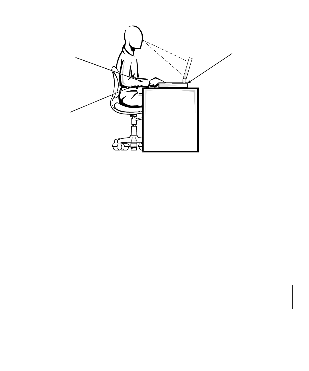
wrists relaxed and flat
arms at desk level
computer positioned
directly in front of user
3. Remove all installed batteries.
4. Ground yourself by touching the unpainted metal
surface of an I/O connector on the back of the
computer.
While you work, periodically touch the connector
to dissipate any static electricity that might harm
internal components.
P
rotecting Against Electrostatic
Discharge
Static electricity can harm electronic components inside
your computer . To prevent static damage, dischar ge static
electricity from your body before you touch any of your
computer’s electronic components, such as a memory
module. You can do so by touching an unpainted metal
surface on the computer’s I/O panel.
As you continue to work inside the computer, periodically touch an I/O connector to remove any static charge
your body may have accumulated.
In addition to the preceding precautions, you can also
take the following steps to prevent damage from electrostatic discharge (ESD):
•
When unpacking a static-sensitive component from its
shipping carton, do not remove the comp onent from
the antistatic packing material until you are ready t o
install the component. Just before unwrapping the
antistatic packaging, be sure to discharge static electricity from your body.
•
When transporting a sensitive component, first place
it in an antistatic container or packaging.
•
Handle all sensitive components in a static-safe area.
If possible, use antistatic floor pads and workbench
pads.
The following caution may appear throughout this document to remind you of these precautions:
CAUTION: See “Protecting Against Electrostatic
Discharge” in the safety instructions at the front of
this guide.
vii
Page 7

viii
Page 8

Preface
A
bout This Guide
This guide is intended for anyone who uses the Dell
Latitude CP portable computer. It can be used by both
first-time and experienced computer users who want to
learn about the features of the computer. This guide also
provides basic troublesh ooti ng procedu r es and inst r uctions for using the Dell Diagnostics to test your computer
and its components.
Summaries of the chapters and appendixes of this guide
follow:
•
Chapter 1, “Introduction,” gives an overview of the
computer features and a list of available upgrades.
•
Chapter 2, “Customizing System Features,”
describes how to use the System Setup program to
change system settings, such as those that control the
computer’s power conservation features.
•
Chapter 3, “Troubleshooting Your Computer,” provides some initial checks and procedures you can use
to solve basic computer problems and some general
guidelines on analyzing software problems. This
chapter also discusses messages and beep codes.
•
Chapter 4, “Running the Dell Diagnostics,”
describes how to check the computer’ s hardware and
use the Dell Diagnostics to isolate component
problems.
•
Chapter 5, “Getting Help,” describes the he lp tools
Dell provides to assist you if you have a problem
with the computer. It also explains how and when to
call Dell for technical assistance.
•
Appendix A, “Technical Specifications,” is intended
primarily as reference material if you are interested
in learning more about the details of your computer.
•
Appendix B, “Diagnostic Video Tests,” provides
samples of screens displayed when the Video test
group of the Dell Diagnostics is run. These screens
help you check a particular video function or group
of functions on the built-in displ a y or an external
monitor.
•
Appendix C, “Regulatory Notices,” is for users who
are interested in which regulatory agencies have
tested and approved the Dell Latitude CP portable
computer.
•
Appendix D, “Warranties and Return Policy,”
describes the warranty and return policy for the Dell
computer .
W
arranty and Return Policy
Information
Dell Computer Corporation (“Dell”) manufactures its
hardware products from parts and components that are
new or equivalent to new in accordance with industrystandard practices.
For information about the Dell warranty and return policy, see Appendix D, “Warranties and Return Policy.”
ix
Page 9
O
ther Documents You May Need
N
otational Conventions
Besides this Referen ce and Troubles hooti ng Gu ide , the fol-
lowing online docu menta tion is incl uded with your
computer:
The Windows-based System User’ s Guide contains essential information you need to use your
portable computer . L ook for the System User’ s
Guide icon in the Dell Accessories folder.
The Dell Q&A provides qui ck a nd deta iled
answers to the questions most commo nly as ked
about using a portable computer. Read this online
document before calling Dell for technical assistance. Look
for the Dell Q&A icon in the Dell Accessories folder.
The Dell Program Diskette Maker helps you
with one of the most critical parts of setting up
your system—creating program diskette sets.
Look for the Program Diskette Maker icon in the Dell
Accessories folder.
Dell Service and Support Policies provides
information about service and suppor t policies,
guarantees, and warranties (in the United
States and Canada only). Look for the Dell Services and
Support Policies icon in the Dell Accessories folder.
You may also have one or more of the following
documents.
NOTE: Documentation updates are sometimes included
with your computer to describe changes to your computer or software. Always read these updates before
consulting any other documentation because the updates
contain the latest information.
Operating system documentation is included if you
•
ordered your operating system software from Dell.
This documentation describes how to install (if necessary), configure, and use your operating system
software.
Documentation is included with any options you
•
purchase separately from your computer. This documentation includes information that you need to
configure and install these options in your Dell
computer.
“Readme” files may be installed on your hard-disk
•
drive to provide last-minute updates about technical
changes to your computer or advanced technical
reference material intended for experienced users or
technicians.
The following subsections list notational conventions
used in this document.
Warnings, Cautions, and Notes
Throughout this guide, there may be blocks of text
printed in color or in italic type. These blocks are warnings, cautions, and notes, and they are used as follows:
WARNING: A WARNING indicates the potential
for bodily harm and tells you how to avoid the
problem.
CAUTION: A CAUTION indi cates either potential
damage to hardware or loss of data and tells you
how to avoid the problem.
NOTE: A NOTE indicates important information that
helps you make better use of your computer.
Typographical Conventions
The following list defines (where appropriate) and illustrates typographical conventions used as visual cues for
specific elements of text throughout this document:
Keycaps, the labeling that appears on the keys on a
•
keyboard, are enclosed in angle brackets.
Example: <Enter>
Key combinations are series of keys to be pressed
•
simultaneously (unless otherwise indicated) to perform a single function.
Exampl e: <Ctrl><Alt><Enter>
Commands presented in lowercase bold are for ref-
•
erence purposes only and are not intended to be
typed at that particular point in the discussion.
Example: “Use the format command to . . . .”
In contrast, commands presented in the Courier
New font are intended to be typed as p art of an
instruction.
Example: “Type
drive A.”
format
to format the diskette in
x
Page 10

•
Filenames and directory names are presented in
lowercase bold.
Examples: autoexec.bat and c:\windows
•
Syntax lines consist of a command and all its possible parameters. Commands are displayed in
lowercase bold; variable parameters (those for which
you substitute a value) are displayed in lowercase
italics; constant parameters are displayed in lowercase bold. The brackets indicate items that are
optional.
Example: del [drive:] [[path]filename] [/p]
•
Command lines consist of a command and may
include one or more of the command’s possible
parameters. Command lines are presented in the
Courier New font.
Example:
del c:\myfile.doc
•
Screen text is text that appears on the screen of your
display or external monitor. It can be a system message, for example, or it can be text that you are
instructed to type as part of a command (referred to
as a command line). Screen text is presented in the
Courier New font.
Example: The following message appears on your
screen:
No boot device available
•
Variables are symbols for which you substitute a
value. They are presented in italics.
Example: module n (where n represents the memory
module number)
xi
Page 11

xii
Page 12

Contents
Safety Instructions. . . . . . . . . . . . . . . . . . . . . . . . . . . . . . . . . . . . . . . .v
When Using Your Computer. . . . . . . . . . . . . . . . . . . . . . . . . . . . . . . . . . . . . . . . . . . . . .v
Ergonomic Computing Habits. . . . . . . . . . . . . . . . . . . . . . . . . . . . . . . . . . . . . . . . . . . . vi
When Removing or Installing Memory Modules . . . . . . . . . . . . . . . . . . . . . . . . . . . . . vi
Protecting Against Electrost atic
Discharge. . . . . . . . . . . . . . . . . . . . . . . . . . . . . . . . . . . . . . . . . . . . . . . . . . . . . . . . . . . .vii
Preface . . . . . . . . . . . . . . . . . . . . . . . . . . . . . . . . . . . . . . . . . . . . . . . . ix
A
bout This Guide . . . . . . . . . . . . . . . . . . . . . . . . . . . . . . . . . . . . . . . . . . . . . . . . . . . ix
Warranty and Return Policy Information . . . . . . . . . . . . . . . . . . . . . . . . . . . . . . . . . . . ix
Other Documents You May Need. . . . . . . . . . . . . . . . . . . . . . . . . . . . . . . . . . . . . . . . . .x
Notational Conventions. . . . . . . . . . . . . . . . . . . . . . . . . . . . . . . . . . . . . . . . . . . . . . . . . .x
Warnings, Cautions, and Notes . . . . . . . . . . . . . . . . . . . . . . . . . . . . . . . . . . . . . . . .x
Typographical Conventions. . . . . . . . . . . . . . . . . . . . . . . . . . . . . . . . . . . . . . . . . . .x
Chapter 1
Introduction . . . . . . . . . . . . . . . . . . . . . . . . . . . . . . . . . . . . . . . . . . . 1-1
Hardware Features. . . . . . . . . . . . . . . . . . . . . . . . . . . . . . . . . . . . . . . . . . . . . . . . . . . . 1-2
Available Options . . . . . . . . . . . . . . . . . . . . . . . . . . . . . . . . . . . . . . . . . . . . . . . . . . . . 1-4
Accessing Online Documentation. . . . . . . . . . . . . . . . . . . . . . . . . . . . . . . . . . . . . . . . 1-4
Getting Help . . . . . . . . . . . . . . . . . . . . . . . . . . . . . . . . . . . . . . . . . . . . . . . . . . . . . . . . 1-4
Chapter 2
Using the System Setup Program . . . . . . . . . . . . . . . . . . . . . . . . . 2-1
Entering the System Setup Program . . . . . . . . . . . . . . . . . . . . . . . . . . . . . . . . . . . . . .2-1
Using the System Setup Program . . . . . . . . . . . . . . . . . . . . . . . . . . . . . . . . . . . . . . . . 2-1
System Setup Options . . . . . . . . . . . . . . . . . . . . . . . . . . . . . . . . . . . . . . . . . . . . . . . . . 2-5
AC . . . . . . . . . . . . . . . . . . . . . . . . . . . . . . . . . . . . . . . . . . . . . . . . . . . . . . . . . . . . 2-5
Admin Password . . . . . . . . . . . . . . . . . . . . . . . . . . . . . . . . . . . . . . . . . . . . . . . . . 2-5
Alarm Resume . . . . . . . . . . . . . . . . . . . . . . . . . . . . . . . . . . . . . . . . . . . . . . . . . . . 2-5
Asset Tag . . . . . . . . . . . . . . . . . . . . . . . . . . . . . . . . . . . . . . . . . . . . . . . . . . . . . . . 2-5
xiii
Page 13

Audio Mode. . . . . . . . . . . . . . . . . . . . . . . . . . . . . . . . . . . . . . . . . . . . . . . . . . . . . 2-5
Battery. . . . . . . . . . . . . . . . . . . . . . . . . . . . . . . . . . . . . . . . . . . . . . . . . . . . . . . . . 2-6
Battery Status . . . . . . . . . . . . . . . . . . . . . . . . . . . . . . . . . . . . . . . . . . . . . . . . . . . 2-6
BIOS Version . . . . . . . . . . . . . . . . . . . . . . . . . . . . . . . . . . . . . . . . . . . . . . . . . . . 2-6
Boot Sequence. . . . . . . . . . . . . . . . . . . . . . . . . . . . . . . . . . . . . . . . . . . . . . . . . . . 2-6
Boot Speed . . . . . . . . . . . . . . . . . . . . . . . . . . . . . . . . . . . . . . . . . . . . . . . . . . . . . 2-6
Brightness . . . . . . . . . . . . . . . . . . . . . . . . . . . . . . . . . . . . . . . . . . . . . . . . . . . . . . 2-6
Click Volume . . . . . . . . . . . . . . . . . . . . . . . . . . . . . . . . . . . . . . . . . . . . . . . . . . . 2-7
Date . . . . . . . . . . . . . . . . . . . . . . . . . . . . . . . . . . . . . . . . . . . . . . . . . . . . . . . . . . . 2-7
Disk Time-Out. . . . . . . . . . . . . . . . . . . . . . . . . . . . . . . . . . . . . . . . . . . . . . . . . . . 2-7
Diskette Drive A . . . . . . . . . . . . . . . . . . . . . . . . . . . . . . . . . . . . . . . . . . . . . . . . . 2-7
Diskette Drive B . . . . . . . . . . . . . . . . . . . . . . . . . . . . . . . . . . . . . . . . . . . . . . . . . 2-7
Diskette Reconfig . . . . . . . . . . . . . . . . . . . . . . . . . . . . . . . . . . . . . . . . . . . . . . . . 2-7
Display Close . . . . . . . . . . . . . . . . . . . . . . . . . . . . . . . . . . . . . . . . . . . . . . . . . . . 2-8
Display Time-Out . . . . . . . . . . . . . . . . . . . . . . . . . . . . . . . . . . . . . . . . . . . . . . . . 2-8
Docking Status . . . . . . . . . . . . . . . . . . . . . . . . . . . . . . . . . . . . . . . . . . . . . . . . . . 2-8
External Cache . . . . . . . . . . . . . . . . . . . . . . . . . . . . . . . . . . . . . . . . . . . . . . . . . . 2-8
External Hot Key. . . . . . . . . . . . . . . . . . . . . . . . . . . . . . . . . . . . . . . . . . . . . . . . . 2-8
Infrared Data Port . . . . . . . . . . . . . . . . . . . . . . . . . . . . . . . . . . . . . . . . . . . . . . . . 2-8
Infrared Mode . . . . . . . . . . . . . . . . . . . . . . . . . . . . . . . . . . . . . . . . . . . . . . . . . . . 2-8
IntelliSpin . . . . . . . . . . . . . . . . . . . . . . . . . . . . . . . . . . . . . . . . . . . . . . . . . . . . . . 2-9
Internal Hard Drive . . . . . . . . . . . . . . . . . . . . . . . . . . . . . . . . . . . . . . . . . . . . . . . 2-9
Keyboard Click . . . . . . . . . . . . . . . . . . . . . . . . . . . . . . . . . . . . . . . . . . . . . . . . . . 2-9
Modular Bay . . . . . . . . . . . . . . . . . . . . . . . . . . . . . . . . . . . . . . . . . . . . . . . . . . . . 2-9
Microprocessor . . . . . . . . . . . . . . . . . . . . . . . . . . . . . . . . . . . . . . . . . . . . . . . . . . 2-9
Parallel Mode . . . . . . . . . . . . . . . . . . . . . . . . . . . . . . . . . . . . . . . . . . . . . . . . . . . 2-9
Pointing Device. . . . . . . . . . . . . . . . . . . . . . . . . . . . . . . . . . . . . . . . . . . . . . . . . 2-10
Power Management. . . . . . . . . . . . . . . . . . . . . . . . . . . . . . . . . . . . . . . . . . . . . . 2-10
Primary Password . . . . . . . . . . . . . . . . . . . . . . . . . . . . . . . . . . . . . . . . . . . . . . . 2-10
Ring/Event Resume. . . . . . . . . . . . . . . . . . . . . . . . . . . . . . . . . . . . . . . . . . . . . . 2-10
S2D Time-Out. . . . . . . . . . . . . . . . . . . . . . . . . . . . . . . . . . . . . . . . . . . . . . . . . . 2-10
Serial Port . . . . . . . . . . . . . . . . . . . . . . . . . . . . . . . . . . . . . . . . . . . . . . . . . . . . . 2-11
Service Tag . . . . . . . . . . . . . . . . . . . . . . . . . . . . . . . . . . . . . . . . . . . . . . . . . . . . 2-11
Smart CPU Mode . . . . . . . . . . . . . . . . . . . . . . . . . . . . . . . . . . . . . . . . . . . . . . . 2-11
Suspend Time-Out. . . . . . . . . . . . . . . . . . . . . . . . . . . . . . . . . . . . . . . . . . . . . . . 2-12
System Memory . . . . . . . . . . . . . . . . . . . . . . . . . . . . . . . . . . . . . . . . . . . . . . . . 2-12
Time . . . . . . . . . . . . . . . . . . . . . . . . . . . . . . . . . . . . . . . . . . . . . . . . . . . . . . . . . 2-12
Universal Connect. . . . . . . . . . . . . . . . . . . . . . . . . . . . . . . . . . . . . . . . . . . . . . . 2-12
Video Memory . . . . . . . . . . . . . . . . . . . . . . . . . . . . . . . . . . . . . . . . . . . . . . . . . 2-12
xiv
Page 14

Chapter 3
Troubleshooting Your Computer . . . . . . . . . . . . . . . . . . . . . . . . . . 3-1
Backing Up Your Files . . . . . . . . . . . . . . . . . . . . . . . . . . . . . . . . . . . . . . . . . . . . . . . . 3-1
Basic Checks . . . . . . . . . . . . . . . . . . . . . . . . . . . . . . . . . . . . . . . . . . . . . . . . . . . . . . . . 3-1
Checking Connections . . . . . . . . . . . . . . . . . . . . . . . . . . . . . . . . . . . . . . . . . . . . . 3-2
Look and Listen. . . . . . . . . . . . . . . . . . . . . . . . . . . . . . . . . . . . . . . . . . . . . . . . . . . . . . 3-3
System Setup Options . . . . . . . . . . . . . . . . . . . . . . . . . . . . . . . . . . . . . . . . . . . . . 3-4
Messages and Codes . . . . . . . . . . . . . . . . . . . . . . . . . . . . . . . . . . . . . . . . . . . . . . . . . . 3-4
System Flash Codes. . . . . . . . . . . . . . . . . . . . . . . . . . . . . . . . . . . . . . . . . . . . . . . 3-9
Finding Software Solutions. . . . . . . . . . . . . . . . . . . . . . . . . . . . . . . . . . . . . . . . . . . . 3 -12
Installing and Configuring Software . . . . . . . . . . . . . . . . . . . . . . . . . . . . . . . . . 3-13
Initialization or Startup Files . . . . . . . . . . . . . . . . . . . . . . . . . . . . . . . . . . . 3-13
Using Software. . . . . . . . . . . . . . . . . . . . . . . . . . . . . . . . . . . . . . . . . . . . . . . . . . 3-13
Error Messages . . . . . . . . . . . . . . . . . . . . . . . . . . . . . . . . . . . . . . . . . . . . . . 3-13
Input Errors. . . . . . . . . . . . . . . . . . . . . . . . . . . . . . . . . . . . . . . . . . . . . . . . . 3-13
Memory-Resident Programs. . . . . . . . . . . . . . . . . . . . . . . . . . . . . . . . . . . . 3-13
Program Conflicts. . . . . . . . . . . . . . . . . . . . . . . . . . . . . . . . . . . . . . . . . . . . 3-14
Avoiding Interrupt Assignment Conflicts. . . . . . . . . . . . . . . . . . . . . . . . . . 3-14
Memory Allocations . . . . . . . . . . . . . . . . . . . . . . . . . . . . . . . . . . . . . . . . . . 3-15
I/O Memory Map . . . . . . . . . . . . . . . . . . . . . . . . . . . . . . . . . . . . . . . . . . . . . . . . 3-15
Troubleshooting Procedures . . . . . . . . . . . . . . . . . . . . . . . . . . . . . . . . . . . . . . . . . . . 3-16
Troubleshooting a Wet Computer . . . . . . . . . . . . . . . . . . . . . . . . . . . . . . . . . . . 3-17
Troubleshooting a Damaged Computer. . . . . . . . . . . . . . . . . . . . . . . . . . . . . . . 3-18
Troubleshooting a Power Failure. . . . . . . . . . . . . . . . . . . . . . . . . . . . . . . . . . . . 3-18
Total Power Failure When Using the AC Adapter. . . . . . . . . . . . . . . . . . . 3-19
Total Power Failure When Using a Battery . . . . . . . . . . . . . . . . . . . . . . . . 3-19
No Power to a Part of the Computer. . . . . . . . . . . . . . . . . . . . . . . . . . . . . . 3-20
Troubleshooting the Diskette Drive. . . . . . . . . . . . . . . . . . . . . . . . . . . . . . . . . . 3-21
Troubleshooting the CD-ROM Drive . . . . . . . . . . . . . . . . . . . . . . . . . . . . . . . . 3-21
Troubleshooting the Hard-Disk Drive . . . . . . . . . . . . . . . . . . . . . . . . . . . . . . . . 3-22
Troubleshooting an External Keyboard or External Keypad. . . . . . . . . . . . . . . 3-23
Troubleshooting Memory. . . . . . . . . . . . . . . . . . . . . . . . . . . . . . . . . . . . . . . . . . 3-23
Troubleshooting the Built-In Display . . . . . . . . . . . . . . . . . . . . . . . . . . . . . . . . 3-24
Troubleshooting an External Monitor . . . . . . . . . . . . . . . . . . . . . . . . . . . . . . . . 3-25
Troubleshooting Serial and Parallel Ports . . . . . . . . . . . . . . . . . . . . . . . . . . . . . 3-26
Troubleshooting the Basic I/O Functions. . . . . . . . . . . . . . . . . . . . . . . . . .3-26
Troubleshooting the Infrared Port. . . . . . . . . . . . . . . . . . . . . . . . . . . . . . . . 3-27
xv
Page 15

Chapter 4
Running the Dell Diagnostics. . . . . . . . . . . . . . . . . . . . . . . . . . . . . 4-1
Features of the Dell Diagnostics. . . . . . . . . . . . . . . . . . . . . . . . . . . . . . . . . . . . . . . . . 4-1
When to Use
the Dell Diagnostics . . . . . . . . . . . . . . . . . . . . . . . . . . . . . . . . . . . . . . . . . . . . . . . . . . 4-1
Before You Start Testing . . . . . . . . . . . . . . . . . . . . . . . . . . . . . . . . . . . . . . . . . . . . . . 4-2
Starting the Dell Diagnostics . . . . . . . . . . . . . . . . . . . . . . . . . . . . . . . . . . . . . . . . . . . 4-2
How to Use the Dell Diagnostics . . . . . . . . . . . . . . . . . . . . . . . . . . . . . . . . . . . . . . . . 4-3
Confirming the System
Configuration Information . . . . . . . . . . . . . . . . . . . . . . . . . . . . . . . . . . . . . . . . . . . . . 4-4
How to Use the Menu. . . . . . . . . . . . . . . . . . . . . . . . . . . . . . . . . . . . . . . . . . . . . . . . . 4-5
Main Menu Options . . . . . . . . . . . . . . . . . . . . . . . . . . . . . . . . . . . . . . . . . . . . . . . . . . 4-5
Run . . . . . . . . . . . . . . . . . . . . . . . . . . . . . . . . . . . . . . . . . . . . . . . . . . . . . . . . . . . 4-5
Select. . . . . . . . . . . . . . . . . . . . . . . . . . . . . . . . . . . . . . . . . . . . . . . . . . . . . . . . . . 4-5
Subtest. . . . . . . . . . . . . . . . . . . . . . . . . . . . . . . . . . . . . . . . . . . . . . . . . . . . . . . . . 4-5
Run (Under Subtest). . . . . . . . . . . . . . . . . . . . . . . . . . . . . . . . . . . . . . . . . . . 4-5
Select (Under Subtest) . . . . . . . . . . . . . . . . . . . . . . . . . . . . . . . . . . . . . . . . . 4-6
Options (Under Subtest). . . . . . . . . . . . . . . . . . . . . . . . . . . . . . . . . . . . . . . . 4-6
Test Limits (Under Subtest). . . . . . . . . . . . . . . . . . . . . . . . . . . . . . . . . . . . . 4-6
About (Under Subtest). . . . . . . . . . . . . . . . . . . . . . . . . . . . . . . . . . . . . . . . . 4-6
Key-Help (Under Subtest) . . . . . . . . . . . . . . . . . . . . . . . . . . . . . . . . . . . . . . 4-6
Quit Menu (Under Subtest) . . . . . . . . . . . . . . . . . . . . . . . . . . . . . . . . . . . . . 4-6
Options . . . . . . . . . . . . . . . . . . . . . . . . . . . . . . . . . . . . . . . . . . . . . . . . . . . . . . . . 4-6
Number of Times to Repeat Test(s). . . . . . . . . . . . . . . . . . . . . . . . . . . . . . . 4-7
Maximum Errors Allowed. . . . . . . . . . . . . . . . . . . . . . . . . . . . . . . . . . . . . . 4-7
Pause for User Response . . . . . . . . . . . . . . . . . . . . . . . . . . . . . . . . . . . . . . . 4-7
Output Device for Status Messages. . . . . . . . . . . . . . . . . . . . . . . . . . . . . . . 4-8
Output Device for Error Messages. . . . . . . . . . . . . . . . . . . . . . . . . . . . . . . . 4-8
Test Limits. . . . . . . . . . . . . . . . . . . . . . . . . . . . . . . . . . . . . . . . . . . . . . . . . . . . . . 4-8
About. . . . . . . . . . . . . . . . . . . . . . . . . . . . . . . . . . . . . . . . . . . . . . . . . . . . . . . . . . 4-9
Key-Help. . . . . . . . . . . . . . . . . . . . . . . . . . . . . . . . . . . . . . . . . . . . . . . . . . . . . . . 4-9
Quit . . . . . . . . . . . . . . . . . . . . . . . . . . . . . . . . . . . . . . . . . . . . . . . . . . . . . . . . . . . 4-9
Tests in the Dell Diagnostics . . . . . . . . . . . . . . . . . . . . . . . . . . . . . . . . . . . . . . . . . . . 4-9
Error Messages. . . . . . . . . . . . . . . . . . . . . . . . . . . . . . . . . . . . . . . . . . . . . . . . . . . . . 4-12
RAM Test Group . . . . . . . . . . . . . . . . . . . . . . . . . . . . . . . . . . . . . . . . . . . . . . . . . . . 4-12
Why Run a RAM Test?. . . . . . . . . . . . . . . . . . . . . . . . . . . . . . . . . . . . . . . . . . . 4-13
Subtests . . . . . . . . . . . . . . . . . . . . . . . . . . . . . . . . . . . . . . . . . . . . . . . . . . . . . . . 4-13
System Set Test Group. . . . . . . . . . . . . . . . . . . . . . . . . . . . . . . . . . . . . . . . . . . . . . . 4-13
Why Run a System Set Test? . . . . . . . . . . . . . . . . . . . . . . . . . . . . . . . . . . . . . . 4-13
xvi
Page 16

Subtests . . . . . . . . . . . . . . . . . . . . . . . . . . . . . . . . . . . . . . . . . . . . . . . . . . . . . . . 4-14
Video Test Group . . . . . . . . . . . . . . . . . . . . . . . . . . . . . . . . . . . . . . . . . . . . . . . . . . .4-15
Why Run a Video Test?. . . . . . . . . . . . . . . . . . . . . . . . . . . . . . . . . . . . . . . . . . . 4-15
Subtests . . . . . . . . . . . . . . . . . . . . . . . . . . . . . . . . . . . . . . . . . . . . . . . . . . . . . . . 4-15
Keyboard Test Group . . . . . . . . . . . . . . . . . . . . . . . . . . . . . . . . . . . . . . . . . . . . . . . . 4-16
Why Run a Keyboard Test?. . . . . . . . . . . . . . . . . . . . . . . . . . . . . . . . . . . . . . . . 4-16
Subtests . . . . . . . . . . . . . . . . . . . . . . . . . . . . . . . . . . . . . . . . . . . . . . . . . . . . . . . 4-16
Mouse Test . . . . . . . . . . . . . . . . . . . . . . . . . . . . . . . . . . . . . . . . . . . . . . . . . . . . . . . . 4-16
Why Run the Mouse Test?. . . . . . . . . . . . . . . . . . . . . . . . . . . . . . . . . . . . . . . . . 4-16
Subtests . . . . . . . . . . . . . . . . . . . . . . . . . . . . . . . . . . . . . . . . . . . . . . . . . . . . . . . 4-16
Diskette Drives Test Group. . . . . . . . . . . . . . . . . . . . . . . . . . . . . . . . . . . . . . . . . . . . 4-17
Why Run a Diskette Drives Test? . . . . . . . . . . . . . . . . . . . . . . . . . . . . . . . . . . . 4-17
Subtests . . . . . . . . . . . . . . . . . . . . . . . . . . . . . . . . . . . . . . . . . . . . . . . . . . . . . . . 4-17
Hard-Disk Drives (Non-SCSI) Test Group . . . . . . . . . . . . . . . . . . . . . . . . . . . . . . . .4-17
Why Run a Hard-Disk Drives Test? . . . . . . . . . . . . . . . . . . . . . . . . . . . . . . . . . 4-17
Subtests . . . . . . . . . . . . . . . . . . . . . . . . . . . . . . . . . . . . . . . . . . . . . . . . . . . . . . . 4-18
IDE CD ROM Drives Test Group. . . . . . . . . . . . . . . . . . . . . . . . . . . . . . . . . . . . . . . 4-18
Why Run an IDE CD ROM Drives Test? . . . . . . . . . . . . . . . . . . . . . . . . . . . . . 4-18
Subtests . . . . . . . . . . . . . . . . . . . . . . . . . . . . . . . . . . . . . . . . . . . . . . . . . . . . . . . 4-18
Serial/Infrared Ports Test Group. . . . . . . . . . . . . . . . . . . . . . . . . . . . . . . . . . . . . . . . 4-18
Why Run a Serial/Infrared Ports Test? . . . . . . . . . . . . . . . . . . . . . . . . . . . . . . . 4-19
Subtests . . . . . . . . . . . . . . . . . . . . . . . . . . . . . . . . . . . . . . . . . . . . . . . . . . . . . . . 4-19
Parallel Ports Test Group . . . . . . . . . . . . . . . . . . . . . . . . . . . . . . . . . . . . . . . . . . . . . 4-19
Why Run a Parallel Ports Test? . . . . . . . . . . . . . . . . . . . . . . . . . . . . . . . . . . . . . 4-19
Subtests . . . . . . . . . . . . . . . . . . . . . . . . . . . . . . . . . . . . . . . . . . . . . . . . . . . . . . . 4-20
SCSI Devices Test Group . . . . . . . . . . . . . . . . . . . . . . . . . . . . . . . . . . . . . . . . . . . . . 4-20
Why Run a SCSI Devices Test?. . . . . . . . . . . . . . . . . . . . . . . . . . . . . . . . . . . . . 4-20
Subtests . . . . . . . . . . . . . . . . . . . . . . . . . . . . . . . . . . . . . . . . . . . . . . . . . . . . . . . 4-20
Network Interface Test Group. . . . . . . . . . . . . . . . . . . . . . . . . . . . . . . . . . . . . . . . . . 4-21
Why Run a Network Interface Test? . . . . . . . . . . . . . . . . . . . . . . . . . . . . . . . . . 4-21
Subtests . . . . . . . . . . . . . . . . . . . . . . . . . . . . . . . . . . . . . . . . . . . . . . . . . . . . . . . 4-21
Audio Test Group . . . . . . . . . . . . . . . . . . . . . . . . . . . . . . . . . . . . . . . . . . . . . . . . . . . 4-22
Why Run an Audio Test. . . . . . . . . . . . . . . . . . . . . . . . . . . . . . . . . . . . . . . . . . . 4-22
Subtests . . . . . . . . . . . . . . . . . . . . . . . . . . . . . . . . . . . . . . . . . . . . . . . . . . . . . . . 4-22
Other Test Group. . . . . . . . . . . . . . . . . . . . . . . . . . . . . . . . . . . . . . . . . . . . . . . . . . . . 4-22
Chapter 5
Getting Help . . . . . . . . . . . . . . . . . . . . . . . . . . . . . . . . . . . . . . . . . . . 5-1
Technical Assistance. . . . . . . . . . . . . . . . . . . . . . . . . . . . . . . . . . . . . . . . . . . . . . . . . . 5-1
xvii
Page 17

Help Tools . . . . . . . . . . . . . . . . . . . . . . . . . . . . . . . . . . . . . . . . . . . . . . . . . . . . . . . . . 5-2
Dell Q&A . . . . . . . . . . . . . . . . . . . . . . . . . . . . . . . . . . . . . . . . . . . . . . . . . . . . . . 5-3
System User’s Guide. . . . . . . . . . . . . . . . . . . . . . . . . . . . . . . . . . . . . . . . . . . . . . 5-3
Reference and Troubleshooting Guide . . . . . . . . . . . . . . . . . . . . . . . . . . . . . . . . 5-3
World Wide Web on the Internet . . . . . . . . . . . . . . . . . . . . . . . . . . . . . . . . . . . . 5-3
Commercial Online Services. . . . . . . . . . . . . . . . . . . . . . . . . . . . . . . . . . . . . . . . 5-3
Dell Diagnostics Program . . . . . . . . . . . . . . . . . . . . . . . . . . . . . . . . . . . . . . . . . . 5-3
AutoTech Service . . . . . . . . . . . . . . . . . . . . . . . . . . . . . . . . . . . . . . . . . . . . . . . . 5-3
TechFax Service . . . . . . . . . . . . . . . . . . . . . . . . . . . . . . . . . . . . . . . . . . . . . . . . . 5-4
TechConnect BBS. . . . . . . . . . . . . . . . . . . . . . . . . . . . . . . . . . . . . . . . . . . . . . . . 5-4
Automated Order-Status System. . . . . . . . . . . . . . . . . . . . . . . . . . . . . . . . . . . . . 5-4
Technical Support Service . . . . . . . . . . . . . . . . . . . . . . . . . . . . . . . . . . . . . . . . . 5-4
Problems With Your Order . . . . . . . . . . . . . . . . . . . . . . . . . . . . . . . . . . . . . . . . . . . . 5-5
Product Information . . . . . . . . . . . . . . . . . . . . . . . . . . . . . . . . . . . . . . . . . . . . . . . . . . 5-5
Returning Items for Warranty Repair or Credit . . . . . . . . . . . . . . . . . . . . . . . . . . . . . 5-5
Before You Call . . . . . . . . . . . . . . . . . . . . . . . . . . . . . . . . . . . . . . . . . . . . . . . . . . . . . 5-5
Dell Contact Numbers . . . . . . . . . . . . . . . . . . . . . . . . . . . . . . . . . . . . . . . . . . . . . . . . 5-7
Appendix A
Technical Specifications. . . . . . . . . . . . . . . . . . . . . . . . . . . . . . . . . A-1
Appendix B
Diagnostic Video Tests. . . . . . . . . . . . . . . . . . . . . . . . . . . . . . . . . . B-1
Video Memory Test . . . . . . . . . . . . . . . . . . . . . . . . . . . . . . . . . . . . . . . . . . . . . . . . . . B-1
Video Hardware Test . . . . . . . . . . . . . . . . . . . . . . . . . . . . . . . . . . . . . . . . . . . . . . . . . B-1
Text Mode Character Test . . . . . . . . . . . . . . . . . . . . . . . . . . . . . . . . . . . . . . . . . . . . . B-1
Character Attributes Subtest (80 x 25) . . . . . . . . . . . . . . . . . . . . . . . . . . . . . . . . B-2
Character Set Subtest (80 x 25). . . . . . . . . . . . . . . . . . . . . . . . . . . . . . . . . . . . . . B-2
Character Attributes Subtest (40 x 25) . . . . . . . . . . . . . . . . . . . . . . . . . . . . . . . . B-2
Character Set Subtest (40 x 25). . . . . . . . . . . . . . . . . . . . . . . . . . . . . . . . . . . . . . B-2
Text Mode Color Test . . . . . . . . . . . . . . . . . . . . . . . . . . . . . . . . . . . . . . . . . . . . . . . . B-2
Color Attributes Subtest (80 x 25) . . . . . . . . . . . . . . . . . . . . . . . . . . . . . . . . . . . B-2
Color Attributes Subtest (40 x 25) . . . . . . . . . . . . . . . . . . . . . . . . . . . . . . . . . . . B-3
Color Bars Subtest. . . . . . . . . . . . . . . . . . . . . . . . . . . . . . . . . . . . . . . . . . . . . . . . B-3
Text Mode Pages Test . . . . . . . . . . . . . . . . . . . . . . . . . . . . . . . . . . . . . . . . . . . . . . . . B-3
Graphics Mode Test . . . . . . . . . . . . . . . . . . . . . . . . . . . . . . . . . . . . . . . . . . . . . . . . . . B-3
320 x 200 Graphics Mode Screens . . . . . . . . . . . . . . . . . . . . . . . . . . . . . . . . . . . B-3
320 x 200 16-Color Graphics Mode Screen . . . . . . . . . . . . . . . . . . . . . . . . . . . . B-3
640 x 200 16-Color Graphics Mode Screen . . . . . . . . . . . . . . . . . . . . . . . . . . . . B-4
640 x 350 16-Color Graphics Mode Screen . . . . . . . . . . . . . . . . . . . . . . . . . . . . B-4
xviii
Page 18

640 x 480 2-Color Graphics Mode Screen . . . . . . . . . . . . . . . . . . . . . . . . . . . . . .B-4
640 x 480 16-Color Graphics Mode Screen. . . . . . . . . . . . . . . . . . . . . . . . . . . . .B-4
320 x 200 256-Color Graphics Mode Screen. . . . . . . . . . . . . . . . . . . . . . . . . . . .B-4
640 x 480 256-Color Graphics Mode Screen. . . . . . . . . . . . . . . . . . . . . . . . . . . .B-4
800 x 600 16-Color Graphics Mode Screen. . . . . . . . . . . . . . . . . . . . . . . . . . . . .B-4
800 x 600 256-Color Graphics Mode Screen. . . . . . . . . . . . . . . . . . . . . . . . . . . .B-4
1024 x 768 16-Color Graphics Mode Screen (External Monitor) . . . . . . . . . . . .B-4
1024 x 768 256-Color Graphics Mode Screen (External Monitor) . . . . . . . . . . .B-5
Color Palettes Test. . . . . . . . . . . . . . . . . . . . . . . . . . . . . . . . . . . . . . . . . . . . . . . . . . . .B-5
Solid Colors Test. . . . . . . . . . . . . . . . . . . . . . . . . . . . . . . . . . . . . . . . . . . . . . . . . . . . .B-5
Appendix C
Regulatory Notices . . . . . . . . . . . . . . . . . . . . . . . . . . . . . . . . . . . . . C-1
FCC Class B Notice (U.S. Only). . . . . . . . . . . . . . . . . . . . . . . . . . . . . . . . . . . . . . . . .C-1
Modem Requirements. . . . . . . . . . . . . . . . . . . . . . . . . . . . . . . . . . . . . . . . . . . . . . . . .C-2
Type of Service . . . . . . . . . . . . . . . . . . . . . . . . . . . . . . . . . . . . . . . . . . . . . . . . . .C-2
Telephone Company Procedures . . . . . . . . . . . . . . . . . . . . . . . . . . . . . . . . . . . . .C-2
If Problems Arise . . . . . . . . . . . . . . . . . . . . . . . . . . . . . . . . . . . . . . . . . . . . . . . . .C-2
Installation and Labeling . . . . . . . . . . . . . . . . . . . . . . . . . . . . . . . . . . . . . . . . . . .C-2
Load Number . . . . . . . . . . . . . . . . . . . . . . . . . . . . . . . . . . . . . . . . . . . . . . . . . . . .C-2
IC Notice (Canada Only). . . . . . . . . . . . . . . . . . . . . . . . . . . . . . . . . . . . . . . . . . . . . . .C-2
Canadian Modem Requirements . . . . . . . . . . . . . . . . . . . . . . . . . . . . . . . . . . . . .C-3
EN 55022 Compliance (Czech Republic Only) . . . . . . . . . . . . . . . . . . . . . . . . . . . . .C-3
CE Notice . . . . . . . . . . . . . . . . . . . . . . . . . . . . . . . . . . . . . . . . . . . . . . . . . . . . . . . . . .C-3
VCCI Notices (Japan Only) . . . . . . . . . . . . . . . . . . . . . . . . . . . . . . . . . . . . . . . . . . . .C-4
Class A ITE . . . . . . . . . . . . . . . . . . . . . . . . . . . . . . . . . . . . . . . . . . . . . . . . . . . . .C-4
Class B ITE . . . . . . . . . . . . . . . . . . . . . . . . . . . . . . . . . . . . . . . . . . . . . . . . . . . . .C-4
Korean Regulatory Notice. . . . . . . . . . . . . . . . . . . . . . . . . . . . . . . . . . . . . . . . . . . . . .C-4
Class A Device. . . . . . . . . . . . . . . . . . . . . . . . . . . . . . . . . . . . . . . . . . . . . . . . . . .C-4
Class B Device. . . . . . . . . . . . . . . . . . . . . . . . . . . . . . . . . . . . . . . . . . . . . . . . . . .C-4
Polish Center for Testing and Certification Notice. . . . . . . . . . . . . . . . . . . . . . . . . . .C-5
Wymagania Polskiego Centrum BadaÒ i Certyfikacji . . . . . . . . . . . . . . . . . . . . . . . .C-5
PozostaŠe instrukcje bezpieczeÒstwa. . . . . . . . . . . . . . . . . . . . . . . . . . . . . . . . . . . . .C-5
NOM 024 Information (Mexico Only) . . . . . . . . . . . . . . . . . . . . . . . . . . . . . . . . . . . .C-6
Información para NOM 024 (únicamente para México). . . . . . . . . . . . . . . . . . . . . . .C-6
Chapter 6
Warranties and Return Policy. . . . . . . . . . . . . . . . . . . . . . . . . . . . . D-1
xix
Page 19

Limited Three-Year Warranty (U.S. and Canada Only) . . . . . . . . . . . . . . . . . . . . . .D-1
Coverage During Year One. . . . . . . . . . . . . . . . . . . . . . . . . . . . . . . . . . . . . . . . . D-1
Coverage During Years Two and Three . . . . . . . . . . . . . . . . . . . . . . . . . . . . . . .D-1
General . . . . . . . . . . . . . . . . . . . . . . . . . . . . . . . . . . . . . . . . . . . . . . . . . . . . . . . . D-2
“Total Satisfaction” Return Policy (U.S. and Canada Only) . . . . . . . . . . . . . . . . . . . D-2
Index . . . . . . . . . . . . . . . . . . . . . . . . . . . . . . . . . . . . . . . . . . . . . . . . . . . 1
xx
Page 20

Figures
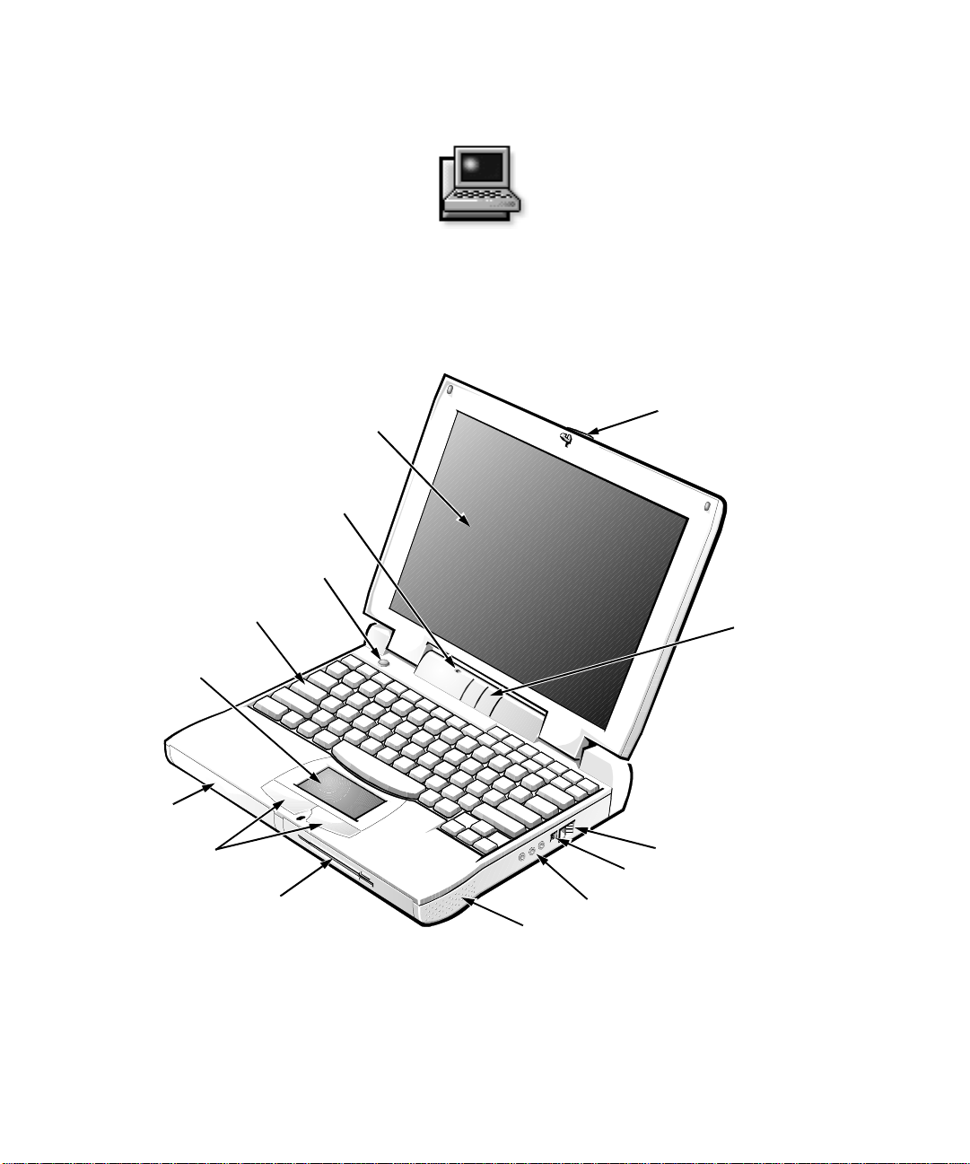
Figure 1-1. Front View of the Computer. . . . . . . . . . . . . . . . . . . . . . . . . . . . . . . . 1-1
Figure 1-2. Back View of the Computer . . . . . . . . . . . . . . . . . . . . . . . . . . . . . . . . 1-2
Figure 2-1. Pages 1 and 2 of the System Setup Program . . . . . . . . . . . . . . . . . . . 2-3
Figure 2-2. Pages 3 and 4 of the System Setup Program . . . . . . . . . . . . . . . . . . . 2-4
Figure 3-1. AC Adapter and Power Cable. . . . . . . . . . . . . . . . . . . . . . . . . . . . . . . 3-2
Figure 3-2. Removing the Battery. . . . . . . . . . . . . . . . . . . . . . . . . . . . . . . . . . . . . 3-2
Figure 3-3. External Cables. . . . . . . . . . . . . . . . . . . . . . . . . . . . . . . . . . . . . . . . . . 3-2
Figure 3-4. Flash Code Indicators . . . . . . . . . . . . . . . . . . . . . . . . . . . . . . . . . . . . 3-10
Figure 3-5. Power, Drive Access, and Battery Indicators. . . . . . . . . . . . . . . . . . 3-16
Figure 4-1. Diagnostics Menu. . . . . . . . . . . . . . . . . . . . . . . . . . . . . . . . . . . . . . . . 4-2
Figure 4-2. Main Screen of the Dell Diagnostics . . . . . . . . . . . . . . . . . . . . . . . . . 4-4
Figure 5-1. Diagnostics Checklist . . . . . . . . . . . . . . . . . . . . . . . . . . . . . . . . . . . . . 5-6
Figure B-1. 80-Column x 25-Line Character Set Subtest Screen . . . . . . . . . . . . .B-2
Figure B-2. 40-Column x 25-Line Character Set Subtest Screen . . . . . . . . . . . . .B-2
Figure B-3. 640 x 480 2-Color Graphics Mode Screen . . . . . . . . . . . . . . . . . . . . .B-4
Tables
Table 2-1. System Setup Navigation Keys. . . . . . . . . . . . . . . . . . . . . . . . . . . . . . 2-2
Table 3-1. Boot Routine Indications . . . . . . . . . . . . . . . . . . . . . . . . . . . . . . . . . . 3-3
Table 3-2. System Error Messages. . . . . . . . . . . . . . . . . . . . . . . . . . . . . . . . . . . . 3-4
Table 3-3. Flash Codes. . . . . . . . . . . . . . . . . . . . . . . . . . . . . . . . . . . . . . . . . . . . 3-11
Table 3-4. IRQ Line Assignments . . . . . . . . . . . . . . . . . . . . . . . . . . . . . . . . . . . 3-14
Table 3-5. Conventional Memory Map . . . . . . . . . . . . . . . . . . . . . . . . . . . . . . . 3-15
Table 3-6. Upper Memory Map . . . . . . . . . . . . . . . . . . . . . . . . . . . . . . . . . . . . . 3-15
Table 3-7. I/O Memory Map . . . . . . . . . . . . . . . . . . . . . . . . . . . . . . . . . . . . . . . 3-16
Table 4-1. Option Parameters. . . . . . . . . . . . . . . . . . . . . . . . . . . . . . . . . . . . . . . . 4-7
Table 4-2. Dell Diagnostics Tests . . . . . . . . . . . . . . . . . . . . . . . . . . . . . . . . . . . 4-10
Table 4-3. RAM Test Switches . . . . . . . . . . . . . . . . . . . . . . . . . . . . . . . . . . . . . 4-13
Table 5-1. Help Tools. . . . . . . . . . . . . . . . . . . . . . . . . . . . . . . . . . . . . . . . . . . . . . 5-2
Table 5-2. International Dialing Codes . . . . . . . . . . . . . . . . . . . . . . . . . . . . . . . . 5-8
Table 5-3. Dell Contact Numbers . . . . . . . . . . . . . . . . . . . . . . . . . . . . . . . . . . . 5-10
Table A-1. Technical Specifications. . . . . . . . . . . . . . . . . . . . . . . . . . . . . . . . . . .A-1
Table B-1. Color Attributes . . . . . . . . . . . . . . . . . . . . . . . . . . . . . . . . . . . . . . . . .B-3
xxi
Page 21

xxii
Page 22
Chapter 1
Introduction
he Dell® Latitude® CP portable computer is an
T
expandable multimedia system designed around an
®
Intel
Pentium® microprocessor with MMX™ and
display
microphone
power button
keyboard
touch pad
battery bay
Peripheral Component Interconnect (PCI) technologies.
This chapter describes the major hardware and software
features of your computer.
display latch
status indicator panel
touch pad buttons
modular bay
Figure 1-1. Front View of the Computer
air intake
AC adapter connector
audio jacks (3)
speaker
Introduction 1-1
Page 23
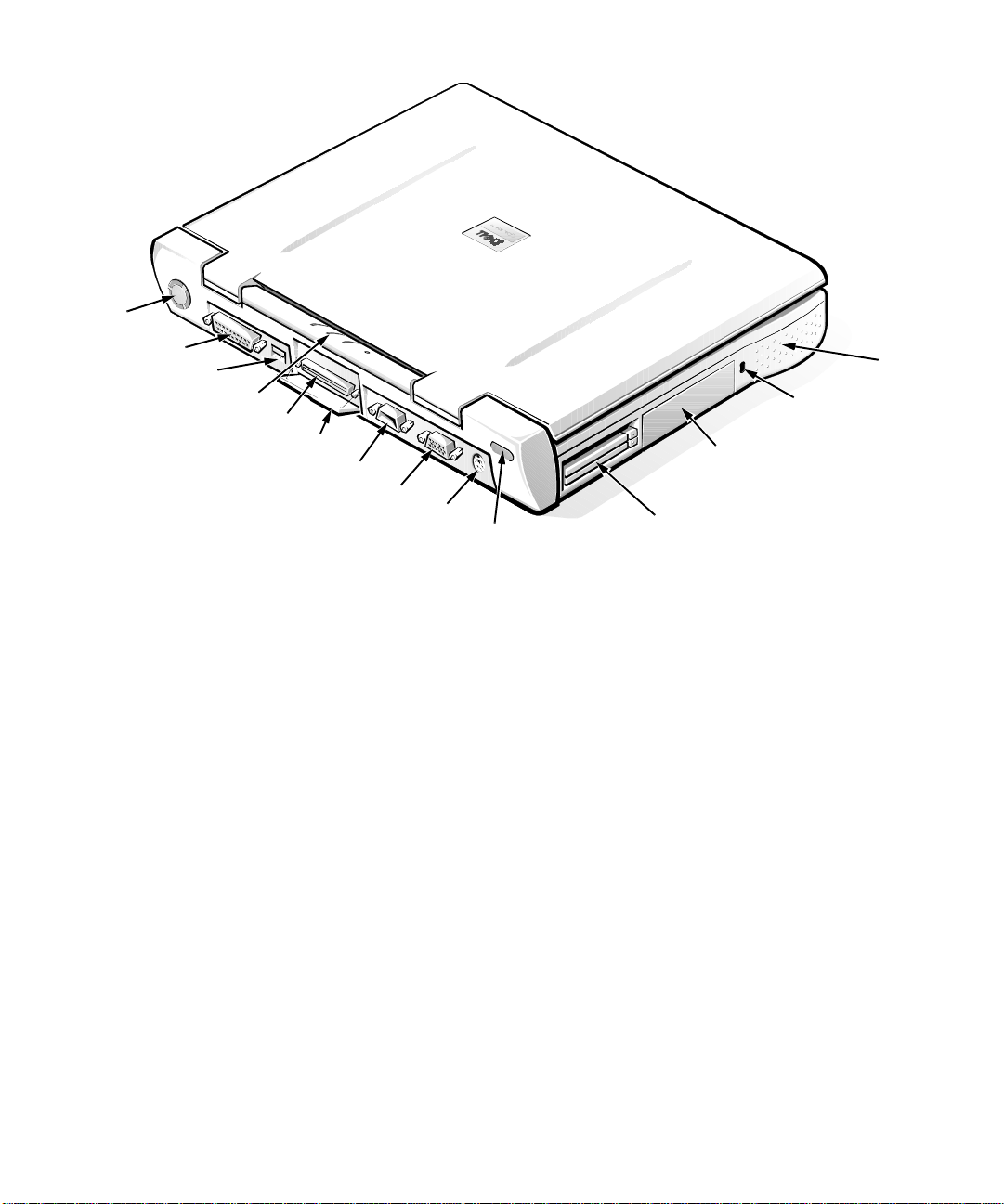
fan
parallel connector
USB connector
status indicator panel
docking connector
docking connector door
serial connector
monitor connector
PS/2 connector
infrared port
PC Card slot
hard-disk drive
Figure 1-2. Back View of the Computer
H
ardware Features
— Software wavetable support, Sound Blaster Pro-
compatible voice and music functions, and SRS
Your Dell computer has the following features:
•
A Pentium microprocessor running at 133, 166, or
233 megahertz (MHz) and a 12.1-inch super video
graphics array (SVGA) active-matrix color display
or a 13.3-inch extended graphics array (XGA)
(1024 x 768) active-matrix color display.
•
Full multimedia capability through the following
standard features:
— A CD-ROM drive that can be used in the modu-
lar bay. When you unpack your computer, look
for the CD-ROM drive in the accessories box of
the shipping carton.
— 128-bit hardware-accelerated video support,
with 2 megabytes (MB) of video memory.
— Support for a zoom video PC Card in the upper
PC Card connector.
•
•
3-D audio co ntrol.
— Three audio jacks for connecting external
speakers or headphones, a microphone, and a
record/playback device to your computer.
— Built-in microphone and two stereo speakers.
A modular bay that supports a CD-ROM drive,
diskette drive, or second battery. To make the computer as light as possible when you travel, use the
special travel module in the modular bay.
NOTE: Your computer was shipped with a diskette
drive in the modular bay. For information on removing the diskette drive and installing a CD-ROM
drive, battery, or travel module in the modular bay,
see the topic titled “Modular Bay” in the online
System User’s Guide
.
A 16- or 32-megabyte (MB) extended-data out
(EDO) memory module standard on the system
board. Memory can be increased up to 128 MB by
speaker
security cable slot
1-2 Dell Latitude CP Reference and Troubleshooting Guide
Page 24

installing combinations of 16-, 32-, and 64-MB
3.3-volt (V) EDO small-outline, dual-inline memory
modules (SoDIMMs) in the two memory module
sockets on the system board.
•
A 256-kilobyte (KB) static random-access memory
(SRAM) external cache (also called level 2, or L2,
cache) on the Latitude CP M133ST and Latitude CP
M166ST . Th e Latitude CP M233S T and Latitude CP
M233XT have a 512-KB SRAM external cache.
Cache memory enhances the speed of many microprocessor operations by storing the most recently
accessed contents of system memory.
•
Two power conservation modes—suspend mode and
suspend-to-disk mode—which help you conserve battery
power . If the batteries run out of power , suspend-to-dis k
mode prevents data loss by copying all system data to the
hard-disk drive and turning off the computer .
•
Connectors for two 3.3-volt (V) or 5-V PC Cards.
The upper PC Card connector supports zoomed
video PC Cards.
NOTE: The PC Card controller supports the
CardBus standard for 32-bit data transfer on the
PC Card.
•
Hardware and software support for the Dell Latitude
C/Port Advanced Port Replicator (C/Port APR) and
the Dell Latitude C/Dock Expansion Station.
•
A touch-pad pointing device positioned for both leftand right-handed users. The left and right touch-pad
buttons mimic mouse buttons; you can also perform
many pointing functions by tapping the touch pad
itself. “Click and drag” buttonless functions are also
supported.
•
A lithium ion battery standard in the battery bay,
with support for a second battery in the modular bay.
ExpressCharge technology charges a single battery
in 1 hour (when the computer is off or in suspend
mode).
NOTE: The batteries are designed to work only with
Dell Latitude CP portable compu ters. Do not use
the batteries with other computers, and do not use
batteries from other computers with the Dell Latitude CP.
WARNING: Do not puncture or incinerate the
battery. When your battery no longer holds a
charge, call your local waste disposal agency or
environmental agency for advice on disposing
of the computer’s lithium ion battery. The lithium ion technology used in the battery is
significantly less ha zard ous to th e environment
than the lithium metal technology used in some
other batteries (such as watch batteries).
•
High-performance parallel and serial ports, and a
multipurpose Personal System/2 (PS/2) connector
for attaching external devices. There is also a monitor connector for attaching an external monitor to
your computer, and a USB connector that supports
standalone and hub devices.
•
An infrared port that permits file transfer without
using cable connections. The port is compatible with
the Infrared Data Association (IrDA) Standard 1.1
(Fast IR) and Standard 1.0 (Slow IR) for use with
external devices.
•
An integrated 16-bit audio controller that provides
sound functions and is Sound Bl aster P ro-compatible.
•
An automatic thermal management system that uses
a variable-speed fan and microprocessor speed
changes to keep the system running at the optimum
temperature.
The following software is included with your Dell
computer system:
•
The Microsoft® Windows® 95 or Windo ws NT® 4.0
or higher oper ating system is installed on your harddisk drive. For more information, see y our operating
system documentation.
•
The System Setup program lets you view and change
the system configuration. For more information,
search on “System Setup program” in the online Sys-
tem User’s Guide or see Chapter 2, “Customizing
System Features.”
•
The Program Diskette Maker, which allows you to
create program diskette sets of software that Dell
installed on your computer’s hard-disk drive.
•
Dell Diagnostics for evaluating the computer’s components and devices.
Introduction 1-3
Page 25

NOTE: If Dell did not instal l an operating s ystem on your
hard-disk drive, the drivers, system utilities, and diagnostics are available separately from Dell. To order, see
Chapter 5, “Getting Help,” for the appr opri ate telephone
number in your location.
Before turning on your computer for the first time, read
all license agreements that came with your computer.
When you turn on yo ur comp uter f or th e first time, if yo u
agree with the license terms, indicate your acceptance by
typing y when pr ompted by the computer . Then complete
the installation of your operating system.
Next, use the Program Diskette Maker in the Dell Accessories folder to create program diskette sets of your
installed software. A program diskette set contains the
complete software package on diskettes. These diskettes
can be used to reinstall or reconfigure the software.
A
vailable Options
As your computing requirements change, you can exte nd
your computer’s capabilities with the C/Port Advanced
Port Replicator or C/Dock Expansion Station. You can
also install a hard-disk drive of larger capacity, increase
system memory, and add functionality with PC Cards.
Dell offers the following devices and upgrade options:
•
C/Port APR and C/Dock Expansion Station
•
Additional bat t eries
•
External keyboards and a numeric keypad
•
External monitors
•
External pointing devices
•
External speakers, headphones, and microphones
•
Printers
•
Hard-disk drives
•
AC adapter
•
PC Cards
•
16-, 32-, and 64-MB memory modules
•
Carrying case
•
Air/auto adapter (for powering the computer from a
special outlet on an airplane or from the cigarette
lighter in a car)
Instructions for connecting or installing these options are
contained in the online System User’s Guide or are
included in the upgrade kit you receive from Dell.
A
ccessing Online Documentat ion
The online System User’s Guide installed on your hard-
disk drive contains information about the following
topics:
•
System features
•
Traveling with the computer
•
Customizing system features
•
Powering the computer and extending battery life
•
Using internal and external devices
•
Maintaining the system
•
Contacting Dell
The guide also contains a glossary of commonly used
computer terms and abbreviations.
To access this guide, select the System User’s
Guide icon in the Dell Accessories folder.
To print any screen from the online System
User’s Guide, display the screen you want and select
Print Topic from the File menu. To print pop-up windows, open the window, click the right touch -pad but to n,
and select Print Topic from the pop-up menu.
NOTE: If Dell did not install an operating system on your
hard-disk drive, or if you need to reinstall the online guide
and did not make a program diskette set, you can download
the online System User’s Guide from Dell’s World Wide
Web site at www.dell.com. Click the Service and Support
icon on Dell’s home page. From the product line menu,
select Latitude Notebooks and then Dell Latitude CP. Select
Technical Information and then select Documentation.
When prompted, save the file t o your hard-disk drive.
G
etting Help
If at any time you don’t underst and a procedure described
in this guide, or if your computer does not perform as
expected, Dell provides a number of tools to help you.
For more information on these help tools, see Chapter 5,
“Getting Help.”
1-4 Dell Latitude CP Reference and Troubleshooting Guide
Page 26
Chapter 2
g
Using the System Setup Program
ach time you turn on your computer, it compares the
E
installed hardware with the system configuration information stored in NVRAM. If the system detects a
discrepancy, it generates an error message for each incorrect configuration se tti n g.
You can use the System Setup program as follows:
•
To set or change user-selectable features—for example, your password or power management features
•
T o veri fy inf ormation about yo ur computer’s current
configuration, such as the amount of system memory
For some setup options, you must reboot the computer
before any changes take ef fec t. Changes for other opt ions
take effect immediately.
NOTE: If you change an option that is activated by
rebooting, the System Setup program displays the setting
you selected rather than the setting currently in effect.
must
You
After you set up your computer, run the System Setup
program to familiarize yourself with your system
configuration information and optional settings. Dell recommends that you write down the information for future
reference.
If the computer is using the Microsoft Windows NT 4.0
operating system, you must use the System Setup pro-
gram to view and change your system configuration.
folder. See the topic titled “Dell Control Center” in the
online System User’s Guide for more information. The
Dell Control Center also contains detailed help that gives
you all the information you need to set options.
reboot for the new setting to take effect.
If the computer is using the Microsoft Windows 95 operating sys t em , yo u can also use
the Dell Control Center to view and change
the system configuration. Access the Dell
Control Center from the Dell Accessories
E
ntering the System Setup
Pro
Enter and use the System Setup program as follows:
If you are using Windows 95, press <Fn><F1> at any
time on the built-in keyboard (or <Scroll Lock><F1> on
an external keyboard if the External Hot Key option is
enabled). If you press <Fn><F3> (or <Scroll Lock><F3>
on an external keyboard if the External Hot Key option is
enabled), the System Setup program opens directly to the
battery status screen.
If you are using Windows NT 4.0 or any other operating
system that is not Plug and Play aware, close all open
application programs and exit the operating system.
When prompted, reboot the computer and press
<Fn><F1> (or <Scroll Lock><F1> from an external keyboard if the External Hot Key option is enabled). If you
wait too long and your operating system beg ins to load
into memory,
then shut down the system and try again.
In either operating system, press <Esc> to exit the System Setup program. If you change the setting of an option
that requires rebooting in order to take effect, exit the
operating system before rebooting. (The Help text in the
upper-right corner of System Setup screens 1, 2, and 4
tells you if the computer must be rebooted.)
NOTE: If the Sy stem Setup program is r unning when the
computer enters suspend mode, the computer exits the
System Setup program and then activates suspend mode.
U
The System Setup screens display the current setup and
configuration information and optional settings for your
ram
let the system complete the load operation
sing the System Setup Program
;
Using the System Setup Program 2-1
Page 27
computer . Infor mation on the scre ens is organ ized in five
boxed areas:
•
Title
The box at the top of all screens lists the page num-
ber, the system name, and the version number of the
basic input/output system (BIOS).
•
Options
The box on the left half of screens 1, 2, and 4 lists
options that define the installed hardware in your
computer and the power conservation and security
features for your computer.
Fields next to the options contain settings or values.
You can change those values that appear bright on
the screen. Options or values that y ou can no t ch ange
(because they are determined or calculated by the
computer) appear less bright.
•
Help
The box on the upper-r ight half of s creens 1, 2, an d 4
displays help information for the option wit h a currently highlighted field.
•
Computer data
The box in the lower-right cor ner of scr eens 1, 2, and
4 displays information about your com puter.
•
Key functions
The line of boxes across the bottom of all screens
lists keys and their functions within the Sy stem
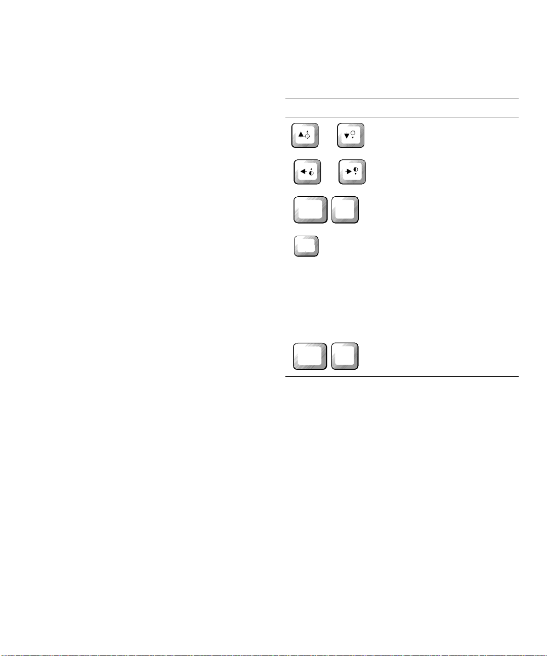
Setup program.
Table 2-1 lists the keys you use to view or change information on the System Setup screens and to exit the
program.
Table 2-1. System Setup Navigation Keys
Keys Action
Moves the cursor to the next
or
field or previous field.
Cycles through available set-
Alt
Esc
Suspend
or
P
tings for an option.
Cycles through the System
Setup pages.
Exits the System Setup program without rebooting the
computer and returns the system to its previous state. If you
changed options that do not
take effect immediatel y, the
changes are recorded but do
not take effect until you reboot
the computer.
Alt
F
Resets all values to their
defaults.
Production Note!!!
2-2 Dell Latitude CP Reference and Troubleshooting Guide
Page 28
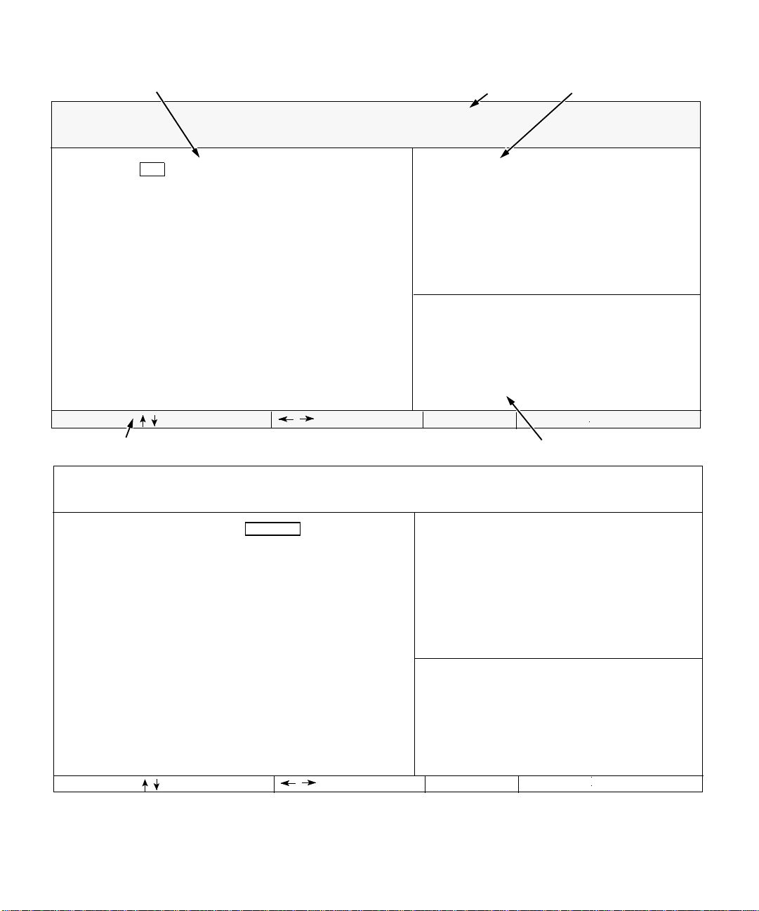
Page 1 of 4
options
title box
Dell Computer Corporation (www.dell.com)
Dell Latitude CP Setup
help
BIOS Version: AXX
Time: 13:17:02 Date: Fri Nov 7, 1997
Internal Hard Drive:
Diskette Drive A:
Diskette Drive B:
Diskette Reconfig:
Modular Bay:
Docking Status:
Universal Connect:
Boot Speed:
Boot Sequence:
2167 MB
Modular Bay
Not Installed
Any Time
Diskette Drive
Undocked
Enabled
166 MHz
Diskette First
change fields
key functions
Dell Computer Corporation (www.dell.com)
Page 2 of 4
Serial Port:
Infrared Data Port:
Infrared Mode:
Parallel Mode:
Audio Mode:
Click Volume:
Keyboard Click:
Dell Latitude CP Setup
COM1
COM3
Fast IR
ECP
Half Duplex
[|||||||]
Disabled
This category sets the time in 24hour format (hours:minutes:seconds)
for the internal clock/calendar.
To change the value in a field, enter
digits or use the left- or rightarrow key to decrease or increase the
value.
Microprocessor:
System Memory:
Video Memory:
External Cache:
Service Tag:
Asset Tag:
change values Esc exit
Alt-P page
Pentium-166/MMX
16 MB
2 MB
256 KB
XXXXX
XXXXX
computer information
BIOS Version: AXX
This category lets you avoid address
conflicts between serial devices by
allowing you to map the address of
the serial port or to disable the
port.
A change to this category takes
effect when you reboot.
Pointing Device:
External Hot Key:
IntelliSpin:
Touch Pad-PS/2 Mouse
Scroll Lock
Variable
************System Security************
Primary Password:
Admin Password:
change fields
Disabled
Disabled
change values Esc exit
Figure 2-1. Pages 1 and 2 of the System Setup Program
Microprocessor:
System Memory:
Video Memory:
External Cache:
Service Tag:
Asset Tag:
Alt-P page
Using the System Setup Program 2-3
Pentium-166/MMX
16 MB
2 MB
256 KB
XXXXX
XXXXX
Page 29
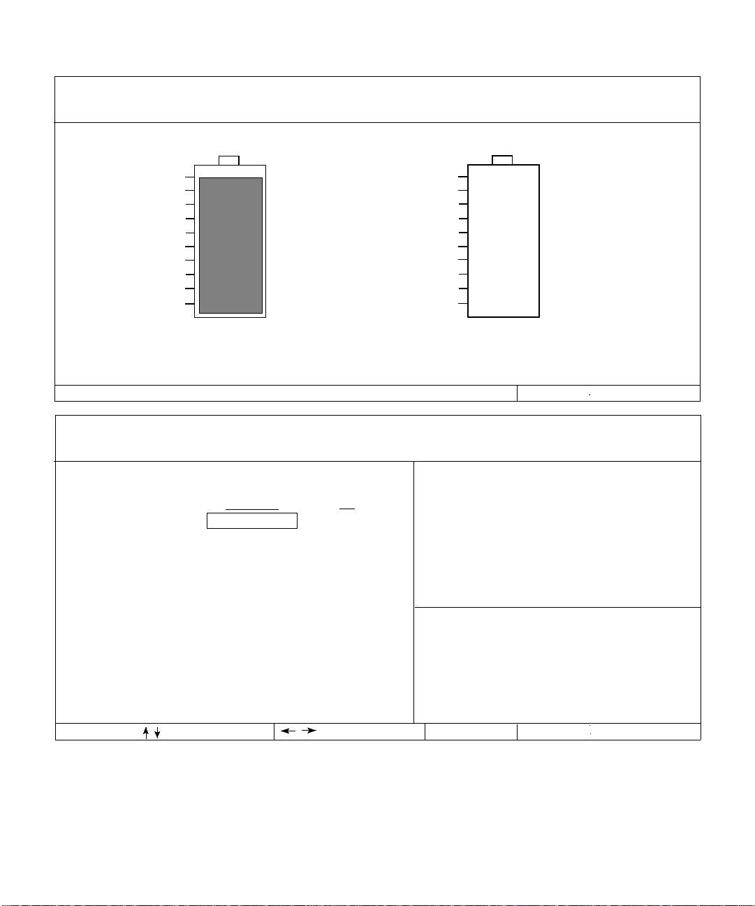
Page 3 of 4
Dell Computer Corporation (www.dell.com)
Dell Latitude CP Setup
BIOS Version: A
XXXXX
Left Battery
100%
90%
80%
70%
60%
50%
40%
30%
20%
10%
100% Charged
Battery Status: Idle Battery Status: Not Installed
Additional batteries and other accessories are available from www.dell.com
Dell Computer Corporation (www.dell.com)
Page 4 of 4
********Power Management********
Power Management:
Display Time-Out:
Disk Time-Out:
Suspend Time-Out:
S2D Time-Out:
Smart CPU Mode:
Brightness:
Ring/Event Resume:
Alarm Resume:
Display Close:
BATTERY
Enabled
4 minutes
3 minute
10 minutes
8 hours
Enabled
[||||||||]
Enabled
Enabled
Suspend
Dell Latitude CP Setup
AC
Disabled
Disabled
Disabled
Disabled
Disabled
Disabled
[||||||]
Right Battery
100%
90%
80%
70%
60%
50%
40%
30%
20%
10%
Alt-P page
When set to DISABLED, this category
disables all power management features. The default setting is
ENABLED.
A change in this category takes
effect immediately.
Battery
Not
Installed
Esc exit
BIOS Version: A
Microprocessor:
System Memory:
Video Memory:
External Cache:
Service Tag:
Asset Tag:
Pentium-166/MMX
16 MB
2 MB
256 KB
XXXXX
XXXXX
XX
change fields
change values Esc exit
Figure 2-2. Pages 3 and 4 of the System Setup Program
2-4 Dell Latitude CP Reference and Troubleshooting Guide
Alt-P page
Page 30

S
ystem Setup Options
The following subsections exp lain in detail the options
found in the System Setup program. The subsections are
alphabetized to make it easy for you to find the appropriate option.
AC
AC is one of the categories of Power Management. You
can set different time-outs for the following options when
you operate your computer from alternating current (AC)
power: Display Time-Out, Disk Time-Out, Suspend
Time-Out, S2D Time-Out, Smart CPU Mode, and
Brightness.
A change to the AC option takes effect immediately
(rebooting is not required).
Admin Password
Admin Password displays the current status of your
administrator password and allows you to assign or
change this password. Settings for this option are:
•
Disabled (the default) — Indicates that no administrator password is assigned
•
Enabled — Indicates that an administrator password
is currently assigned
The administrator password is designed fo r use by system administrators and service technicians in corporate
environments. If an administrator password is assigned,
you can use it to access the computer even if you do not
know the primary password.
CAUTION: The password features provide a high
level of security for the data in your computer.
However, they are not foolproof. If your data
requires more security, it is your respons ibility to
obtain and use additional f orms o f protection, such
as data encryption programs or PC Cards with
encryption features.
Alarm Resume
The Alarm Resume option directs the computer to
resume normal operati on wh en it i s in su spend mode and
detects an alarm from the real-time clock (RTC). Such
alarms can be set through various application programs.
In order for the alarms in these programs to work, the
Alarm Resume option must be set to Enabled.
Settings for this option are:
•
Enabled (the default) — Resumes normal operation
when the computer detects an alarm
•
Disabled — Keeps the computer in suspend mode
even if the computer detects an alarm
A change to the Alarm Resume option takes effect immediately (rebooting is not req uired).
Asset Tag
The Asset Tag option dis plays th e asset tag cod e if you or
your organization assigned one to your computer.
See the topic titled “Asset Tag Utility” in the online Sys-
tem User’s Guide for information on assigning an asset
tag code.
Audio Mode
Audio Mode helps you manage the resources of the computer and the external devices you use with it.
Settings for this option are:
•
Half Duplex (the default) — Allows you to play or
record sounds, but not both at the same time. Use
this setting if the Parallel Mode option is set to ECP
and the Infrared Mode option is set to Fast IR.
•
Disabled — Disables the audio controller and makes
the direct memory access (DMA), interrupt request
(IRQ), and input/output (I/O) resources available for
another serial device to use.
•
Full Duplex — Allows the computer’s audio system
to play and record sounds simultaneously.
For a change in the Audio Mode option to take effect,
you must reboot your computer.
NOTES: The Sys t em Setup program limits the options
available for Audio Mode, depen ding on how t he Parallel
Mode and Infrared Mode options are set. If Parallel
Mode is set to ECP and Infrared Mode is set to Fast IR,
the Audio Mode option cann ot be set to Full Duplex. This
limitation is based on the numbe r of available 8- bit DMA
channels.
Using the System Setup Program 2-5
Page 31

The value selected for Audio Mode determines the boot
configuration for the device. If Windows 95 finds other
available resources, the operating system may upgrade
the configuration.
Battery
Battery is one of the categories of Power Management.
You can set different time-outs for the following options
when you operate your computer from battery power:
Display Time-Out, Disk Time-Out, Suspend Time-Out
S2D Time-Out, Smart CPU Mode, and Brightness.
A change to the Battery option takes effect immediately
(rebooting is not required).
,
Battery Status
Battery Status (Page 3 of the System Setup screens) is a
graphical representation of the approximate amount of
charge left in the main and secondary batteries. There are
no user-selectable settings for this option. If there is no
battery installed in the main battery compartment or in
the modular Bay, the battery gauge illustration says
Battery Status: Not Installed.
If you are not in the System Setup program, you can see
the battery gauge illustration at any time by pressing
<Fn><F3>.
BIOS Version
BIOS Version displays the version number and release
date of the BIOS in your computer. A service technician
may ask you for this version number if you call Dell for
technical assistance.
NOTE: Dell may periodically offer revisions of the BIOS
that add features or solve specific problems. Because the
BIOS for your computer is stored on a reprogrammable
flash-memory chip, you can use the Flash BIOS Update
program to update your computer ’s BIOS entirely
through software.
Boot Sequence
Boot Sequence determines which disk device your computer uses to find the software needed to start the
operating system.
The term boot refers to the computer’s start-up procedure. When you turn on the computer, it “bootstraps”
itself into an operational state by loading into memory a
small program, which in turn loads the necessary operating system. Boot Sequence tells the computer where to
find the files that it needs to load.
Settings for this option are:
•
Diskette First (the default) — Causes your computer
to attempt first to boot from a bootable diskette
If the computer detects no diskette in the diskette
drive, it tries to boot from the hard-disk drive. If the
computer encounters a diskette without the required
boot files or detects a problem with the diskette
drive, it displays an error message.
•
Hard Disk Only — Causes your computer to boot
only from the hard-disk drive
If it fails to boot from th e har d-disk drive for any reason, your computer does no t attempt to boot from the
diskette drive.
For a change in the Boot Sequence option to take effect,
you must reboot your computer.
Boot Speed
Boot Speed allows you to choose between the computer’ s
processing speed (the default) and Compatible, a slower
compatibility speed. The compatibility speed va ri es,
depending on the configuration of your system.
When you change the setting in the Boot Speed option,
the System Setup prog ram stores and con tinues to displ ay
the new setting even if you do not reboot your computer
when you exit the S ys tem S et up program. If you start the
System Setup program again during your current work
session, the processing speed displayed for the Boo t
Speed option may not match the actual speed at which
your computer is running.
For a change in the Boot Speed option to take effect, yo u
must reboot your computer.
Brightness
Brightness allows you to select the brightness of the
display when the computer is op erating on bat tery power.
Use the left- and right-arrow keys to change the brightness of the display. When the computer is powered by a
battery, the default setting for Brightness is the minimum.
If the computer is using AC power, the default setting is
maximum.
2-6 Dell Latitude CP Reference and Troubleshooting Guide
Page 32

A change to the Brightness option becomes effective
immediately (rebooting is not required).
Click Vo lume
Click Volume allows you to disable or adjust the volume
of the keyboard clicks if the Keyboard Click option is
enabled. The default setting for Click Volume is
maximum.
A change to the Click Volume option takes effect immediately (rebooting is not required).
Date
Date resets the date on the computer’s internal calendar.
Your computer automatically displays the day of the
week corresponding to the settings in the three fields that
follow (month, day-of-the-month, and year).
A change to the Date option becomes effective immediately (rebooting is not required). However, you must
reboot to make the change apparent to the operating
system.
To change the date, press the right-arrow key to increase
the number in the highlighted field, or press the leftarrow key to decrease the number. If you prefer, you can
type in numbers in the month and day-of-the-month
fields.
Disk Time-Out
Disk Time-Out lets you determine how long your harddisk drive remains idle before the drive motor turns off to
conserve battery power.
The AC category is set to Disabled. There are no userselectable settings for this option. Settings for the Battery
category are:
•
Disabled
•
15 Seconds
•
1 Minute
•
2 Minutes
•
3 Minutes
•
4 Minutes
•
5 Minutes
•
10 Minutes
•
15 Minutes
•
30 Minutes
•
1 Hour
The default setting is 3 Minutes if the computer is powered by a battery or 1 Mi nute if the com puter is usi ng AC
power. To increase battery operating time, set Disk TimeOut to a lower number. However, if your software
requires frequent hard-disk drive accesses, using a higher
time-out setting may save battery p ower an d time by
minimizing the number of times the hard-disk drive must
power up.
NOTE: Set Disk Time-Out to Disabled if using it causes
compatibility problems with your software.
A change to the Disk Time-Out option takes effect immediately (rebooting is not req uired).
If you are not in the Sy st em S et up program, you can turn
off the hard-disk drive immediately by pressing
<Fn><h>. The drive resumes normal operation automatically when it is accessed by the microprocessor.
Diskette Drive A
Diskette Drive A identifies the location of the 3.5-inch
diskette drive: Modular Bay, Parallel Port, or Not
Installed. There are no user-selectable settings for the
Diskette Drive A option.
Diskette Drive B
Diskette Drive B identifies the location of a second
3.5-inch diskette drive: Parallel Port, Modular Bay, or
Not Installed. There are no user-selectable settings for the
Diskette Drive B option.
Diskette Reconfig
Diskette Reconfig allows application programs that
access the diskette drive to run at their optimum speed.
Settings are At Reboot Only and Any Time.
When Diskette Reconfig is set to Any Time (the default),
you do not have to reboot after installing a diskette drive
in the modular bay or attaching a diskette drive to the
parallel connector on the back of the computer . However ,
some application programs—such as vir us scan s—t hat
access the diskette drive will run very slowly if the
diskette drive is not in the modular bay or connected to
the parallel port. When Diskette Reconfig is set to At
Reboot Only, such application programs run at normal
speed, but you must reboot after installing or attaching a
diskette drive.
Using the System Setup Program 2-7
Page 33

Display Close
Display Close lets you determine whet her you r computer
enters suspend mode when the display is closed, or
whether only the display is turned off.
Settings for this option are:
•
Suspend (the default) — Allows the computer to
enter suspend mode when the display is closed
•
Active — Turns off the display, but does not put the
computer into suspend mode
Display Time-Out
Display Time-Out lets you decide how long the computer
operates with no input/output (I/O) activity before turning off the display to conserve battery power.
Settings for this option in both the AC and Battery categories are:
•
Disabled
•
1 Minute
•
2 Minutes
•
3 Minutes
•
4 Minutes
The default setting is 4 Minutes. To increase battery operating time, set Display Time-Out to a lower number of
minutes.
NOTE: Set the Display Time-Out option to Disabled if
using it causes compatibilit y problems with your
software.
A change to the Display Time-Out option takes effect
immediately (rebooting is not required).
If you are not in the System Se tup program, you can turn
off the display immediately by pressing <Fn><d>. The
display resumes normal operation auto matically when
you press a key, move the cursor, or press the power
button.
•
5 Minutes
•
10 Minutes
•
15 Minutes
•
30 Minutes
•
1 Hour
Docking Status
Docking Status shows whether the computer is attached
to the Dell Latitude C/Port Advanced Port Replicator
(APR) or C/Dock Expansion Station. There are no userselectable settings for the Docking Status option.
External Cache
External Cache tells you how much external cache your
computer has. There are no user-selectable settings for
the External Cache option.
External Hot Key
External Hot Key lets you use the <Scroll Lock> key on
an external keyboard the s ame way y ou us e the <F n> key
on the computer’s built-in keyboard. Set this option to
Scroll Lock (the default) if you are using an ex ternal k eyboard. Set this option to Not Installed to disable this
function on the external keyboard.
Infrared Data Port
Infrared Data Port allows you to avoid resource conflicts
by remapping the address of the inf rared port o r disabling
the port. The COM1, COM2, COM3, and COM4 settings
allow you to take advantage of the computers’s Fast IR
support.
Settings for this option are:
•
Disabled — Disables the infrared data port and
makes the DMA, IRQ, and I/O resources available
for another serial device to use
•
COM1 — Maps the infrared data port to COM1
•
COM2 — Maps the infrared data port to COM2
•
COM3 (the default) — Maps the infrared data port to
COM3
•
COM4 — Maps the infrared data port to COM4
For a change in the Infrared Data Port option to take
effect, you must reboot your computer.
Infrared Mode
The Infrared Mode option appears on the screen only
after an address is assigned in the Infrared Data Port
option. Infrared Mode lets you select Fast IR mode or
Slow IR mode for use with an infrared device. Select
Slow IR if the Parallel Mode option is set to ECP and the
Audio Mode option is set to Full Duplex.
NOTES: The Sys t em Setup program limits the options
available for Infrared Mode, depending on how the Parallel Mode and Audio Mode options are set. If Parallel
Mode is set to ECP and Audio Mode is set to Full
2-8 Dell Latitude CP Reference and Troubleshooting Guide
Page 34

Duplex, the Infrared Mode option cannot be set to Fast
IR. This limitation is based on the number of available
8-bit direct-memory access (DMA) channels.
The value selected for Infrared Mode d etermines the boot
configuration for the device. If Windows 95 finds other
available resources, the operating system may upgrade
the configuration.
IntelliSpin
IntelliSpin lets you compensate for unbalanced or warped
CDs, which can cause the computer to vibrate when the
CD-ROM drive is in use. This option allows you t o us e
discs that might otherwise be unreadable. This opti on is
available for CD-ROM drives with speeds of 6X or higher .
If this option is set to High Performance (the default), the
CD-ROM drive always runs at the highest speed. If this
option is set to Variable, the CD-ROM drive automatically lowers its speed to reduce or stop the vibration
caused by an unbalanced CD.
NOTE: When this option is set to Variable, the CD-ROM
drive may take several seconds to determine the proper
speed. You cannot access the disc during that time.
Internal Hard Drive
Internal Hard Drive displays the capacity of the computer’s hard-disk drive. This option does not h a ve any
user-selectable settings.
Keyboard Click
Keyboard Click lets you choose whether the built-in keyboard makes audible clicking sounds. The Click Volume
option must be enabled for this option to function. The
volume of the simulated key clicks is controlled by the
setting in the Click Volume option .
Settings for this option are Disabled (the default) and
Enabled.
A change to the Keyboard C lick option takes effect immediately (rebooting is not r equired ).
Modular Bay
Modular Bay identifies the kind of device—Diskette
Drive, Battery, or CD-ROM Drive—that is installed in
the modular bay. If there is no device in the modular
bay—or if a travel bay is installed—this option reads Not
Installed. There are no user-selectable settings for this
option.
Microprocessor
Microprocessor displays the type and speed of the microprocessor installed on your computer’s system board.
There are no user-selectable settings for this option.
Parallel Mode
Parallel Mode controls whether the computer’s built-in
parallel port acts as a PS/2-compatible (Bidirectional)
port, A T-compatible (Normal) port, or Extended Capabilities Port (ECP)-compatible port. The default setting for
Parallel Mode is ECP.
Windows 95 uses ECP protocol automatically if it detects
an ECP-capable device.
Set this category according to the type of peripheral
device connected to the parallel port. To determine the
correct mode to use, see the documentation that came
with the device.
NOTE: The ECP settings also work for most software written
for the AT (unidirectional) and PS/2 (bidirectional or normal) modes. Devices that use ECP mode may come with
special drivers that need to be installed in order t o use these
modes.
Setting Parallel Mode to Disabled disables th e parallel
port and its assigned LPT address, freeing its interrupt fo r
another device to use.
For a change in the Parallel Mode option to take effect, you
must reboot your computer .
NOTES: The Sys t em Setup program limits the options
available for Parallel Mo de, depending on how th e Audio
Mode and Infrared Mode options are set. If Audio Mode
is set to Full Duplex and Infrared Mode is set to Fast IR,
the Parallel Mode option cannot be set to ECP. This
limitation is based on the number of available 8-bit
direct-memory access (DMA) channels.
The value selected for Parallel Mode determines the boot
configuration for the device. If Windows 95 finds other
available resources, the operating system may upgrade
the configuration.
Using the System Setup Program 2-9
Page 35

Pointing Device
Pointing Device enables and disables the computer’s
touch pad.
Settings for this option are:
•
T ouch Pad-PS/2 Mouse (the default)
•
Serial Mouse — Disables the touch pad and allows
you to use a mouse connected to the serial connector
on the I/O port
If you want to use a serial mouse, you must first set the
Pointing Device option to Serial Mouse.
For a change in the Pointing Device option to take effect,
you must reboot your computer.
Power Management
Power Management (Page 4 of the System Setup screens)
allows you to enable or disable power conservation features when the computer is being powered b y a battery o r
AC power.
If you want to use any of the time-out options while usi ng
battery power, the Battery
you want to use the time-out options while using AC power, the
AC
option must be set to Enabled.
A change to the Power Management option takes effect
immediately (rebooting is not required).
option must be set to Enabled. If
Primary Pa ssword
Primary Password displays the current status of the primary password and allows you to assign or change this
password.
Settings for this option are:
•
Disabled (the default) — Indicates that no primary
password is assigned
•
Enabled — Indicates that a primary password is currently assigned
If you assign a primary password, the computer prompts
you for the password each time you boot the computer.
CAUTION: The password features provide a high
level of security for the data in your computer.
However, they are not foolproof. If your data
requires more security, it is your responsibility to
obtain and use additional forms o f protection, such
as data encryption programs or PC Cards with
encryption features.
Ring/Event Resume
Ring/Event Resume lets you determine if the comp uter
exits suspend mode when an installed modem card
receives an incoming call. This feature must be supported
by your modem PC Card and you r oper a tin g s ystem , and
must be enabled in the modem device driver.
Settings for this option are:
•
Enabled (the default) — Resumes normal operation
when the computer detects a modem ring
•
Disabled — Keeps the computer in suspend mode
when the computer detects a modem ring
NOTES: Dell recommends that you set Ring/Event
Resume to Disabled when an external serial device,
a modem
In order fo r the Ring/E vent Resume option to work properly ,
this feature must be enabled in the device driver for your modem
PC Card. All drivers su pplied by Dell with your computer ar e
configured to all ow the computer to r esume normal operation
when a modem receives an incoming call. If you use a PC Car d
that you did not receive from Dell, check the documentation to
make sure this featur e is enabled.
A chan ge to the Ring/Event Resume option takes effect
immediately (rebooting is not required).
, is connected to your computer .
other than
S2D Time-Out
S2D Time-Out lets you determine how long your computer remains idle (no I/O activity) before activating
suspend-to-disk mode to conserve battery power.
2-10 Dell Latitude CP Reference and Troubleshooting Guide
Page 36

Settings for this option in both the AC and Battery categories are:
•
Disabled
•
30 Minutes
•
1 Hour
•
2 Hours
•
3 Hours
A change to the S2D Time-Out option takes effect immediately (rebooting is not required).
If you are not in the System Setup program, you can activate suspend-to-di s k mode at any tim e by pres si n g
<Fn><a>. P r e s s t h e p o w e r s w i t c h t o r e s u m e f rom s u s p e n d - t o disk mode.
•
4 Hours
•
6 Hours
•
8 Hours (default)
•
12 Hours
Serial Port
Serial Port allows you to map the address of the serial
port or to disable the serial port.
Settings for this option are:
•
COM1 (the default) — Maps the serial port to
COM1
•
COM2 — Maps the serial port to COM2
•
COM3 — Maps the serial port to COM3
•
COM4 — Maps the serial port to COM4
•
Disabled — Disables the serial port and its assigned
COM address, freeing that interrupt for another
device to use
For a c hange in the Serial Port option to take effect, you
must reboot your computer.
Service Tag
Service Tag displays the computer’s five-character service code, which was prog rammed into NVR AM by Dell
during the manufacturing process. Be prepared to supply
this identification during technical assistance or service
calls. The service tag is also accessed by certain Dell support software, including diagnostics.
There are no user-selectable settings for this option.
NOTE: Convert the service tag number into an express
service code when prompted to do so the first time you
turn on the computer (or use the program in the Dell
Accessories folder). Keep the code handy in case you call
Dell for technical assistance. The code h e lps Dell’s automated support telephone system direct your call more
efficiently.
Smart CPU Mode
Smart CPU Mode allows the computer to slow down the
microprocessor automatically if it is not being actively
used.
Settings for this option are:
•
Enabled — Allows the computer to slow down the
microprocessor when it is inactive
•
Disabled — Keeps the microprocessor running at its
normal operating speed regardless of micropr ocessor
inactivity
The default for Smart CPU Mode is Enabled if the computer is operating on battery power. If the computer is
using AC power, the default for this option is Disabled.
To increase battery operating time, set the Smart CPU
Mode option to Enabled.
When the Smart CPU Mode
processor is inactive, the computer slows the microprocessor to
save power.
NOTES: Some communications software may not work
properly when Smart CPU Mode is enabled. Dell recommends that you set Smart CPU Mode
using communications softwar e.
Interactive application programs shou ld function well
when Smart CPU Mode
programs include spr eadsheet, text editor, graphics design,
entertainment, educational, and utility progr ams.) However , you
may experience performance degradation when recalculati ng a
large spr eadsheet or during an extensive scr een r edraw in a
graphical program. Benchmark utilities may not perf orm as
intended when doing micropr ocessor speed test s. If the softwar e
you use suffers significant performance degradation, set Smart
CPU Mode to Disabled.
A change to the Smart CPU Mode option takes ef fect immediately (rebooting is not required).
option is enabled and the micro-
to Disabled if you are
is enabled. (Examples of interactive
Using the System Setup Program 2-11
Page 37

Suspend Time-Out
Suspend Time-Out lets you determine how long your
computer remains idle before activating suspend mode to
conserve battery power.
Settings for this option in both the AC and Battery categories are:
•
•
•
•
•
Disabled
1 Minute
2 Minutes
3 Minutes
4 Minutes
•
5 Minutes
•
10 Minutes (default)
•
15 Minutes
•
30 Minutes
•
1 Hour
There are no user-selectable settings for this option. The
amount of memory displayed changes if you install or
remove a memory module.
Time
Time resets the time on the computer’s internal clock.
Time is kept in a 24-hour format (hours:minutes:
seconds).
NOTE: If a network server controls the time reflected by
the Time option, changing this option has no eff ect.
A chang e to the Time option becomes effective immediately (rebooting is not required). However, you must reboot
to make the change apparen t to the o peratin g system .
T o increase battery operating time, set the Suspend TimeOut option to a lower number of minutes.
NOTE: Set the Suspend Time-Out option to Disabled if
using it causes compatibility problems with your software.
A change to the Suspend Time-Out option takes effect
immediately (rebooting is not required).
If you are not in the System Setup program, you can activate suspend mode at any time by pressing <Fn><Esc>.
The computer resumes normal operation au tomatically when
you press a key on the built-in keyboard.
System Memory
System Memory displays the total amount of dynamic
random-access memory (DRAM) installed in your computer. The amount of memory displayed includes a
standard 16-megabyte (MB) memory module, plus any
memory modules installed in your computer.
Universal Connect
The Universal Connect option functions with the Dell
Latitude C/Port APR if the computer uses Windows 95.
Set this category to Enabled (the default) if you often
use more than one C/Port APR and want to minimize the
initialization time when you connect the replicator to the
computer. When this category is set to Disabled, the
C/Port APR is reinitialized each time it is connected to
the computer .
Video Memory
Video Memory displays the amount of video memory
installed on the system board. There are no userselectable settings for this option.
2-12 Dell Latitude CP Reference and Troubleshooting Guide
Page 38

Chapter 3
Troubleshooting Your Computer
f your Dell computer is not working as expected, this
I
chapter provides initial checks for solving basic computer problems as well as detailed troubleshoo ting
procedures. It lists system messages and flash codes,
their possible causes, and actions you can take to resolve
any problems indicated by a message or code. This chapter also offers general guidelines for analyzing some
software problems.
NOTES: When you see the question “Is the problem
resolved?” in a troubleshooting procedure, repeat the
operation that caused the problem to see if it still occurs.
To use key combinations on an external keyboard, enable
the External Hot Key option in th e System Setup pr og ram
and use the <Scroll Lock> key instead of the <Fn> key.
B
acking Up Your Files
Y ou can lose data when a computer failure occu rs. If your
computer is behaving erratically, back up your files
immediately . See your operating system documentation
for instructions on backing up files.
B
asic Checks
The following procedure leads you through the checks
necessary to solve some basic computer problems:
1. Is your computer wet or damage d?
Yes. Go to “Troubleshooting a Wet Computer” or
“Troubl eshooting a Damaged Comput er” found la ter
in this chapter.
No. Continue to step 2.
2. Perform the steps in the next subsection, “Checking Connections.”
Is the problem resolved?
Yes. A connection to your computer was loose. You
have fixed the problem.
No. Continue to step 3.
3. Perform the steps in “Look and Listen” found
later in this chapter.
Did your computer complete the start-up (boot)
routine?
NOTE: The boot routine is the operating system’s
attempt to load its files into memory from the bootup sector on the har d -disk dri ve or bootabl e diskette .
It is normal for the computer’s keyboard indicators
to flash briefly during the boot routine.
Yes. Continue to step 4.
No. Call Dell for technical assistance. (See Chap-
ter 5, “Getting Help,” for instructions.)
4. Did you receive a system message or flash code?
Yes. Go to “Messages and Codes” found later in this
chapter.
No. Continue to step 5.
5. Verify, and corr ect if necessary, the System Setup
settings as explained in Chapter 2, “Customizing
System Features.”
Is the problem resolved?
Yes. The system configuration information was
incorrect. You have fixed the problem.
No. Continue to step 6.
6. Run the Dell Diagnostics. (See Chapter 4, “Running
the Dell Diagnostics.”)
Troubleshooting Your Computer 3-1
Page 39

Checking Connections
Loose or improperly connected cables are likely sources
of problems for you r computer , ex ternal moni tor , or o ther
peripherals (such as a printer, external keyboard, or
mouse). A quick check of all cable connections can easily
solve these problems. If a connector has two small
screws, make sure the screws are tight. In addition, check
for damage d or frayed cables.
Be sure the following items are properly connected or
installed:
•
The AC adapter and power cable
•
The battery
battery
AC adapter cable
AC adapter
AC power cable (to
AC power source)
Figure 3-1. AC Adapter and Power Cable
Figure 3-2. Removing the Battery
•
All cables to external devices
USB connector
serial connector
parallel connector
docking connector
video connector
Figure 3-3. External Cables
PS/2 connector
infrared port
3-2 Dell Latitude CP Reference and Troubleshooting Guide
Page 40

L
ook and Listen
Looking at and listening to your computer is important in
determining the source of a problem. Look and listen for
Table 3-1. Boot Routine Indications
Look for: Action
An error message See “Messages and Codes” found later in this chapter.
The power indicator If the computer’s power indicator does not come on, see “Troubleshooting a Power Failure”
found later in this chapter.
the indications described in Table 3-1. If looking and
listening to the computer does not resolve the problem,
see the next subsection, “System Setup O ptions.”
The keyboard
indicators
The drive access
indicator
A series of flashing
lights
An unfamiliar constant scraping or
grinding sound when
you access a drive
The absence of a
familiar sound
NOTE: For the full name of an abbreviation or acronym used in this table, see the Glossary in the online System User’s Guide.
If the Num Lock, Caps Lock, and Scroll Lock ind icators flash simultaneously after the boot routine, see “System Flash Codes” found later in this chapter.
Press the <Num Lock>, <Caps Lock>, a nd <Scroll Lock> k eys to togg le their r espective keyboa rd
indicators on an d of f. If t he ind icator s do not ligh t up, run th e Keybo ard t est gr oup i n th e Dell Di agnostics. (For instructions, see Chapter 4, “Running the Dell Diagnostics.”)
The drive access indicator should flicker when you access data on the diskette drive, harddisk drive, or CD-ROM drive. If the power indicator, drive access indicator, and battery indicator flash simultaneously, see “System Flash Codes” found later in this chapter.
See “Messages and Codes” found later in this chapter.
Make sure the sound is not caused by the application program you are running. The sound
could also be caused by a hardware malfunction. See Chapter 5, “Getting Help,” for instructions on obtaining technical ass istance from Dell.
When you turn on your computer, you can hear the hard-disk drive spin up and the computer
trying to access the boot files from the hard-disk drive or the diskette drive. If your computer
does not boot, call Dell for technical assistance. (See Chapter 5, “Getting Help,” for instructions.) Otherwise, see Chapter 4, “Running the Dell Diagnostics.”
Troubleshooting Your Computer 3-3
Page 41

System Setup Options
You can easily correct certain system problems by verifying the settings for system setup options. When you boot
your computer, it compares the system configuration
information with the current hardware configuration. If
your computer’s hardware configuration doesn’t match
the information recorded by the system setup options, an
error message may appear on your display.
To fix this problem, correct the appropriate system setup
options and reboot your computer. See Chapter 2, “Customizing System Features,” for detailed information.
If, after checking the system setup options, you have not
resolved the problem, see Chapter 4, “Running the Dell
Diagnostics.”
M
essages and Codes
Your application programs, operating system, and the
computer itself are capable of identifying problems and
alerting you to them. When this occurs, a message may
appear on the computer’s display or on an external monitor (if one is attached), or a flash code may sound.
If an error message appears on the display or external
monitor, make a note of the message. See Table 3-2 for
an explanation of the message and suggestions for correcting any errors. The messages are listed alphabetically .
NOTE: If the message is not listed in Table 3-2, check the
documentati on for the application program that was running at the time the message appeared and/or the
operating system documentation for an explanation of
the message and a recommended action.
Table 3-2. System Error Messages
Message Cause Action
Auxiliary device
failure
Bad command or file
name
Cache
disabled due to
failure
Data error The diskette or hard-disk drive
Decreasing available memory
The integrated touch pad or
external PS/2 mouse may be
faulty.
The command you entered does
not exist or is not in the pathname you specified.
The primary cache internal to
the microprocessor has failed.
cannot read the data.
One or more memory modules
may be faulty or improperly
seated.
If you are using an external mouse only , check the
connection for a loose or improperly connected
cable. (See “Checking Connections” found earlier
in this chapter.) If the problem persists, enable the
Pointing Device option. (For instructions, see
“Pointing Device” in Chapter 2, or see the topic
titled “Dell Control Center” in your online System
User’s Guide.) If the problem persists, call Dell
for technical assistance. (See Chapter 5, “Getting
Help,” for instructions.)
Make sure you have typed the command correctly, placed spaces in the proper location, and
used the correct pathname.
Call Dell for technical assistance. (For instructions, see Chapter 5, “Getting Help.”)
Run the appropriate utility to check the file structure of the diskette drive or hard-disk drive. See
the documentation that came with your operating
system.
See “Troubleshooting Memory” found later in
this chapter.
NOTE: For the full name of an abbreviation or acronym used in this table, see the Glossary in the online System User’s Guide.
3-4 Dell Latitude CP Reference and Troubleshooting Guide
Page 42

Table 3-2. System Error Messages
Message Cause Action
(continued)
Disk C: failed
initialization
Diskette drive 0
seek failure
The hard-disk drive failed initialization.
A cable may be loose, or the
system configuration information may not match the
hardware configuration.
Diskette read
failure
Diskette subsystem
reset failed
Diskette writeprotected
A cable may be loose, or the
diskette may be faulty.
The diskette drive controller
may be faulty.
Because the diskette is writeprotected, the operation cannot
be completed.
Drive not ready No diskette is in the diskette
drive, or no hard-disk drive is
in the drive bay. The operation
requires a diskette in the drive
or a hard-disk drive in the bay
before it can continue.
See “Troubleshooting the Hard-Disk Drive”
found later in this chapter.
See “Troubleshooting the Diskette Drive” found
later in this chapter.
If the diskette-drive access indicator lights up, try
a different diskette. If the problem persists, see
“Troubleshooting the Diskette Drive” found later
in this chapter.
Run the Diskette Drive test group in the Dell
Diagnostics. (For instructions, see Chapter 4, “Running the Dell Diagnostics.”)
Slide the write-protect notch up.
Put a diskette in the drive, or push the diskette all
the way into the drive until the eject button pops
out. Or, install a hard-disk drive in the drive bay.
Error reading
PCMCIA card
The computer cannot identify
the PC Card.
Reseat the card or try another PC Card that you
know works. If the problem persists, see
“Troubleshooting a PC Card” found later in this
chapter.
Extended memory
size has changed
The amount of memory
recorded in NVRAM does not
match the memory installed in
Reboot the computer. If the error appears on the
display again, call Dell for technical assistance.
(See Chapter 5, “Getting Help,” for instructions.)
the computer.
Gate A20 failure An installed memory module
may be loose.
General failure The operating system is unable
to carry out the command.
See “Troubleshooting Memory” found later in
this chapter.
This message is usually followed by specific
information—for example, PRINTER OUT OF
PAPER. Respond by t aking t he app ropriate acti on.
NOTE: For the full name of an abbreviation or acronym used in this table, see the Glossary in the online System User’s Guide.
Troubleshooting Your Computer 3-5
Page 43

Table 3-2. System Error Messages
Message Cause Action
(continued)
Hard-disk drive
configuration error
Hard-disk drive
controller failure 0
Hard-disk drive
controller failure 1
Hard-disk drive
failure
Hard-disk drive
read failure
The computer cannot identify
the drive type.
The hard-disk drive does not
respond to commands from the
computer.
The CD-ROM drive does not
respond to commands from the
computer.
The hard-disk drive does not
respond to commands from the
computer.
The hard-disk drive may be
faulty.
Turn off the computer , remove the drive, and boot the
computer from a bootable diskette. Then turn off the
computer, reinstall the drive, and reboot the computer.
Run the Hard-Disk Drive test group in the Dell Diagnostics. (For instructions, see Chapter 4, “Running
the Dell Diagnostics.”)
Turn of f the computer , remove the dr ive, and boot
the computer from a bootable diskette. Then turn
off the computer again, reinstall the drive, and
reboot the computer. If the problem persists, tr y
another drive. Then run the Hard-Disk Driv e test
group in the Dell Diagnostics. (For instructions, see
Chapter 4, “Running the Dell Diagnostics.”)
See “Troubleshooting the CD-R OM Drive” found
later in this chapter.
Turn of f the computer , remove the dr ive, and boot
the computer from a bootable diskette. Then turn
off the computer again, reinstall the drive, and
reboot the computer. If the problem persists, tr y
another drive. Then run the Hard-Disk Driv e test
group in the Dell Diagnostics. (For instructions, see
Chapter 4, “Running the Dell Diagnostics.”)
See “Troubleshooting the Hard-Disk Drive”
found later in this chapter.
Invalid configuration information–
please run System
Setup program
The system configuration
information does not match the
hardware configuration. This
message is most likely to occur
Correct the appropriate options in the System
Setup program. (For instructions, see “Using the
System Setup Program” in Chap ter 2.)
after a memory module is
installed.
Keyboard clock
line failure
Keyboard controller failure
A cable or connector may be
loose, or the keyboard may be
faulty.
A cable or connector may be
loose, or the keyboard may be
faulty.
Run the Keyboard Controller Test in the Dell
Diagnostics. (For instructions, see Chapter 4, “Running the Dell Diagnostics.”)
Reboot the computer, and avoid touching the keyboard or the mouse duri ng the b oot rou tin e. If the
problem persists, run the Keyboard Controller
Test in the Dell Diagnostics. (For instructions, see
Chapter 4, “Running the Dell Diagnostics.”)
NOTE: For the full name of an abbreviation or acronym used in this table, see the Glossary in the online
3-6 Dell Latitude CP Reference and Troubleshooting Guide
System User’s Guide.
Page 44

Table 3-2. System Error Messages
Message Cause Action
(continued)
Keyboard data line
failure
Keyboard stuck key
failure
Memory address
line failure at
address
value
, read
expecting
value
Memory
allocation error
Memory data line
failure at
address
value
, read
expecting
value
A cable or connector may be
loose, or the keyboard may be
faulty.
If an external keyboard or keypad is being used, a cable or
connector may be loose or the
keyboard may be faulty.
If the built-in keyboard is being
used, the keyboard may be
faulty.
A key on the built-in keyboard
or external keyboard may have
been pressed while the computer was booting.
An installed memory module
may be faulty or improperly
seated.
The software you are attempting
to run is conflicting with the
operating system, another appli cation program, or a utility.
An installed memory module
may be faulty or improperly
seated.
Run the Keyboard Controller Test in the Dell
Diagnostics. (For instructions, see Chapter 4, “Running the Dell Diagnostics.”)
Run the Stuck Key Test in the Dell Diagnostics.
(For instructions, see Chapter 4, “Running the Dell
Diagnostics.”)
See “Troubleshooting Memory” found later in
this chapter.
Turn off the computer, wait 30 seconds, and then
restart it. Try to run the program again. If the
problem persists, contact the software company.
See “Troubleshooting Memory” found later in
this chapter.
Memory double word
logic failure at
addres
value
s, read
expecting
An installed memory module
may be faulty or improperly
seated.
See “Troubleshooting Memory” found later in
this chapter.
value
Memory odd/even
logic failure at
address
value
, read
expecting
An installed memory module
may be faulty or improperly
seated.
See “Troubleshooting Memory” found later in
this chapter.
value
NOTE: For the full name of an abbreviation or acronym used in this table, see the Glossary in the online
Troubleshooting Your Computer 3-7
System User’s Guide.
Page 45

Table 3-2. System Error Messages
Message Cause Action
(continued)
Memory write/read
failure at
address
value
, read
expecting
An installed memory module
may be faulty or improperly
seated.
value
No boot device
available
No boot sector on
hard-disk drive
No timer tick
interrupt
Non-system disk or
disk error
The computer cannot find the
diskette or hard-disk drive.
The operating system may be
corrupted.
A chip on the system board
may be malfunctioning.
The diskette in drive A or your
hard-disk drive does not have a
bootable operating system
installed on it.
Not a boot diskette There is no operating system on
the diskette.
See “Troubleshooting Memory” found later in
this chapter.
If the diskette drive is your boot device, make
sure there is a bootable diskette in the drive. If the
hard-disk drive is your bo ot device, make sure th e
drive is installed, properly seated, and partitioned
as a boot device.
Reinstall your operating system. See the documentation that came with your operating system.
Run the System Set test group in the Dell Diagnostics. (For instructions, see Chapter 4, “Running
the Dell Diagnostics.”)
If you are trying to boot from the diskette, replace
it with one that has a bootable operating system.
If you are trying to boot fro m the hard -disk dri ve,
see “Troubleshooting the Hard-Disk Drive”
found later in this chapter.
Boot the computer with a diskette that contains an
operating system.
Optional ROM bad
checksum
Sector not found The operating system cannot
The optional ROM apparently
failed.
locate a sector on the diskette or
hard-disk drive. You probably
have a bad sector or corrupted F A T
Call Dell for technical assistance. (For instructions, see Chapter 5, “Getting Help.”)
Run the appropriate utility to check the file structure
on the diskette or hard-disk drive. If a large n u m be r
of sectors are defective, back up the data (if possible),
and then reformat the diskette or hard-disk drive.
on the diskette or hard-d isk dr ive.
Seek error The operating system cannot
find a specific track on the diskette or hard-disk drive.
If the error is on the diskette drive, try another
diskette in the drive. If the error persists, see
“Troubleshooting the Diskette Drive” found later
in this chapter. If the error is on the hard-disk
drive, see “Troubleshooting the Hard-Disk
Drive” found later in this chapter.
NOTE: For the full name of an abbreviation or acronym used in this table, see the Glossary in the online
3-8 Dell Latitude CP Reference and Troubleshooting Guide
System User’s Guide.
Page 46

Table 3-2. System Error Messages
Message Cause Action
(continued)
Shutdown failure A chip on the system board
may be malfunctioning.
Time-of-day clock
lost power
Time-of-day clock
stopped
Time-of-day not
set—please run the
System Setup
program
Timer chip counter
2 failed
Unexpected
interrupt in
protected mode
Data stored in NVRAM has
become corrupted.
The reserve battery that supports the data stored in
NVRAM may be dead.
The time or date stored in the
System Setup program do es not
match the system clock.
A chip on the system board
may be malfunctioning.
The keyboard controller may be
malfunctioning, or an installed
memory module may be loose.
Run the System Set t es t group in the Dell Di agnostics. (For instructions , see Chapter 4 , “Running t he
Dell Diagnostics.”)
Connect your computer to AC power to charge
the battery. If the problem persists, try to restore
the data. To restore the data, press <Fn><F1> to
enter the System Setup program. Then imm ediately
exit it (as described in “Using the System Setup Program” in Chapter 2). If the message reappears, call
Dell for technical assistance. (For instructions, see
Chapter 5, “Getting Help.”)
Connect your computer to AC power to charge
the battery. If the problem persists, call Dell for
technical assistance. (For instructions, see Chapter 5, “Getting Help.”)
Correct the settings for the Date and Time options.
(For instructions, see “Using the System Setup Program” in Chapter 2.)
Run the System Set t es t group in the Dell Di agnostics. (For instructions , see Chapter 4 , “Running t he
Dell Diagnostics.”)
Run the RAM test group and the Keyboard Controller Test in the D e ll D i a g n o s t i c s . ( F o r i n s t r u c t i o n s ,
see Chapter 4, “Running the Dell Diagnostics.”)
Warning! Battery
is critically low.
NOTE: For the full name of an abbreviation or acronym used in this table, see the Glossary in the online System User’s Guide.
System Flash Codes
When errors that occur during the boot routine cannot be
reported on the bu ilt-i n di s pla y o r on an ex ternal monitor
(if attached), the Num Lock, Caps L ock, and Scroll Lo ck
indicators may flash together in a pattern of lights (or
flash code) that identifies the problem. For example, one
flash, followed by a second flash, and then a burst of
The battery is running out of
charge.
Replace the battery, or connect the computer to
AC power. Otherwise, activate suspend-to-disk
mode or turn off the computer. (For more information, see the topic titled “Final Low-Battery
Warning” in the online System User’ s Guide.)
three flashes (code 1-1-3) means that the computer was
unable to read the data in nonvolatile random-access
memory (NVRAM). This information is important to the
Dell support staff if you need to call for technical
assistance.
Troubleshooting Your Computer 3-9
Page 47

The Num Lock, Caps Lock, and Scroll Lock indicators
flash briefly when the computer is turned on. The flash
codes, if needed, occur after the boot routine.
Num Lock indicator
Caps Lock indicator
Scroll Lock indicator
Figure 3-4. Flash Code Indicators
When a flash code is emitted, write it down on a copy of
the Diagnostics Checklist found in Chapter 5, and then
look it up in Table 3-3. If you are unable to resolve the
problem by looking up the meaning of the flas h code, use
the Dell Diagnostics to identify a more serious cause. (See
Chapter 4, “Running the Dell Diagnostics.”) If you are still
unable to resolve the problem, call Dell for technical assistance. (See Chapter 5, “Getting Help,” for instructions.)
Table 3-3 lists the flash codes and possible corrective
actions.
3-10 Dell Latitude CP Reference and Troubleshooting Guide
Page 48

Message Cause Action
Table 3-3. Flash Codes
1-1-3 NVRAM write/read
failure.
1-1-4 ROM BIOS check-
sum failure.
1-2-1 Programmable inter-
val timer failure.
1-2-2 DMA initialization
failure.
1-2-3 DMA page register
write/read failure.
1-3-1
through
2-4-4
An installed memory module is not
being properly identified or used.
3-1-1 Slave DMA register
failure.
Ru n the System Set test group in the Dell Diagnostics. (See Chapter 4, “Running
the Dell Diagnostics,” for instructions.) If the program does not load, call Dell for technical assistance. (For instructions, see Chapter 5, “Getting Help.”)
Ru n the System Set test group in the Dell Diagnostics. (See Chapter 4, “Running
the Dell Diagnostics,” for instructions.) If the program does not load, call Dell for technical assistance. (For instructions, see Chapter 5, “Getting Help.”)
Ru n the System Set test group in the Dell Diagnostics. (See Chapter 4, “Running
the Dell Diagnostics,” for instructions.) If the program does not load, call Dell for technical assistance. (For instructions, see Chapter 5, “Getting Help.”)
Ru n the System Set test group in the Dell Diagnostics. (See Chapter 4, “Running
the Dell Diagnostics,” for instructions.) If the program does not load, call Dell for technical assistance. (For instructions, see Chapter 5, “Getting Help.”)
Ru n the System Set test group in the Dell Diagnostics. (See Chapter 4, “Running
the Dell Diagnostics,” for instructions.) If the program does not load, call Dell for technical assistance. (For instructions, see Chapter 5, “Getting Help.”)
Make sure a memory module is installed in one of the memory module sockets
on the system board. The computer will not function unless there is at least one
installed memory module. If there is a memory module installed, see “Troubleshooting Memory” found later in this chapter.
Ru n the System Set test group in the Dell Diagnostics. (See Chapter 4, “Running
the Dell Diagnostics,” for instructions.) If the program does not load, call Dell for technical assistance. (For instructions, see Chapter 5, “Getting Help.”)
3-1-2 Master DMA regis-
ter failure.
Ru n the System Set test group in the Dell Diagnostics. (See Chapter 4, “Running
the Dell Diagnostics,” for instructions.) If the program does not load, call Dell for technical assistance. (For instructions, see Chapter 5, “Getting Help.”)
3-1-3 Master interrupt
mask register fail-
Call Dell for technical assistance. (For instructions, see Chapter 5, “Getting
Help.”)
ure.
3-1-4 Slave interrup t
mask register fail-
Call Dell for technical assistance. (For instructions, see Chapter 5, “Getting
Help.”)
ure.
3-2-4 Keyboard controller
test failure.
3-3-4 Display memory test
failure.
NOTE: For the full name of an abbreviation or acronym used in this table, see the Glossary in the online
Run the Keybo ard Controller Test in t he Dell Diagnostics. (For instructions, see
Chapter 4, “Running the Dell Di agnostics.”)
Run the Video Memory Test in the Dell Diagnostics. (For instructions, see Chapter 4, “Running the Dell Diagnostics.”)
Troubleshooting Your Computer 3-11
System User’ s Guide
.
Page 49

Table 3-3. Flash Codes
Message Cause Action
(continued)
3-4-1 Display initializa-
tion failure
3-4-2 Display retrace test
failure
4-2-1 No timer tick Call Dell for technical assistance. (For instructions, see Chapter 5, “Gett ing Help. ”)
4-2-2 Shutdown failure Call Dell for technical assistance. (For instructions, see Chapter 5, “Getting Help.”)
4-2-3 Gate A20 failure Call Dell for technical assistance. (For instructions, see Chapter 5, “Getting Help.”)
4-2-4 Unexpected interrupt
in protected mode
4-3-1 Memory failure
above address
0FFFFh
4-3-3 Timer chip co unter 2
failure
4-3-4 Time-of- day clock
stopped
4-4-1 Serial port failure Run the Serial/Infrared Ports test gr oup in th e Dell Diag nostics. (F or instruct ions, see
5-1-2 No usable memory Run the RAM test group in the Dell Diagnost ics. (For instructions, see Chapter 4,
Run the Video test group in the Dell D i a g nos t i c s . (F o r i n struc t i ons, s e e Chapt e r 4 ,
“Running the Dell Diagnostics.”)
Run the Video test group in the Dell D i a g nos t i c s . (F o r i n struc t i ons, s e e Chapt e r 4 ,
“Running the Dell Diagnostics.”)
Call Dell for technical assistance. (For instructions, see Chapter 5, “Getting Help.”)
Run the RAM test group in the Dell Diagnostics. (For instructions, see Chapter 4,
“Running the Dell Diagnostics.”)
Call Dell for technical assistance. (For instructions, see Chapter 5, “Getting
Help.”)
Call Dell for technical assistance. (For instructions, see Chapter 5, “Getting
Help.”)
Chapter 4, “Running the Dell Di agnostics.”)
“Running the Dell Diagnostics.”)
NOTE: For the full name of an abbreviation or acronym used in this table, see the Glossary in the online System User’s G uide.
•
F
inding Software Solutions
Because most computers have several application programs installed in addition to the operating system,
isolating a software problem can be confusing. Software
errors can also appear to be hardware malfunctions at
first. Software problems can result from the following
circumstances:
•
Improper installati on or config urat i on of a program
•
Input errors
•
Device drivers that may conflict with certain application programs
3-12 Dell Latitude CP Reference and Troubleshooting Guide
Memory conflicts resulting from the use of terminate-and-stay-resident (TSR) programs, such as
device drivers
•
Interrupt conflicts between devices
You can confirm that a computer problem is caused by
software by running the System Set test group as
described in Chapter 4, “Running the Dell Diagnostics.” If
all tests in the test group complete successfully, the error condition is most likely caused b y software .
The following subsections provide some general guidelines for analyzing software problems. For detailed
troubleshooting information on a particular program, see
Page 50

the documentation that accompanied the software or consult the support service for the software.
Installing and Configuring Software
When you obtain software, check it for viruses with
virus-scanning software before installing it on your computer’s hard-disk drive. V iruses, which are pieces of code
that can replicate themselves, can quickly use all available system memory, damage and/or destroy data stored
on the hard-disk drive, and permanently affect the perfo rmance of the programs they infect. Several commercial
virus-scanning programs are available for purchase, and
most bulletin board services (BBSs) archive freely distributed virus-scanning programs that you can download
with a modem.
Before installing a program, read its documentation to
learn how the prog ram works, what hardware it requires,
and what its defaults are. A program usually includes
installation instructions in its accompanying documentation and a software installation routine on its program
diskettes.
The software installation routine assists you in transferring the appropriate program files to your computer’s
hard-disk drive. Installation instructions may provide
details about how to configure your operating system
to run the program successfully. Always read the
installation instructions before running a program’s
installation routine. You may be instructed to modify the
initialization or startup files of your operating system.
When you run the installation routine, be prepared to
respond to prompts for information about how your computer’s operating system is configured, what type of
computer you have, and what peripherals are connected
to your computer.
Initialization or Startup Files
Whenever you start or reboot your computer, your operating system executes commands it finds in its
initialization or startup files.
These files contain commands that automatically
configure the operating environment by setting system
parameters, starting memory-resident programs, and
loading device driver software. If you experience
program conflicts or memory error messages, check
the commands for memory-resident programs in the
initialization or startup files of your operating system. If a
program or peripheral does not work correct ly, check the
documentation that came with the product to see if you
need to modify these files.
Using Software
The following subsections discuss errors that can occur
while using your software.
Error Messages
Error messages can be produced by an application program, the operating system, or the computer. “Messages
and Codes,” found earlier in this chapter, discusses the
error messages that are generated by the comp uter. If you
receive an error message that is not listed in that section,
check your operating system or application program
documentation.
Input Errors
If a specific key or set of keys is pressed at the wrong
time, a program may give you unexpected results. See the
documentation that came with your appli cation program to
make sure the values or characters you are enteri ng are valid.
Make sure the operating environment is set up to accommodate the programs you use. Keep in mind that
whenever you change the parameters of the computer’s
operating environment, you may affect the successful
operation of your programs. Occasionally, when you
modify the operating environment, you may need to reinstall a program that no longer runs properly.
Memory-Resident Programs
There are a variety of utilities and supplementary programs that can be loaded either when the computer boots
or from an operating system prompt. These pr ogr ams are
designed to stay resident in system memory and thus
always be available for use. Because they remain in the
computer’s memory, memory conflicts and errors can
result when other programs require use of all or part of
the memory already occupied by these TSR programs.
T ypi call y, your operating system’s initialization or st artup files contain commands to start TSR programs when
you boot your computer. If you suspect that one of these
TSR programs is causing a memory conflict, remove the
Troubleshooting Your Computer 3-13
Page 51

commands that start them from the start-up file. If the
problem you were experiencing does not recur, one of the
TSR programs probably created the conflict. Add the TSR
commands back into the start-up files one at a time until
you identify which TSR program is creati ng the confl ict.
Program Conflicts
Some programs may leave portions of their setup information behind, even though you have exited from them.
As a result, other programs cannot run. Rebooting your
computer can confirm whether or not these programs are
the cause of the problem.
Other programs use specialized subroutines called device
drivers that can cause problems in your computer. For example, a variation in the way the data is sent to an external
monitor may require a special screen driver program that
expects a certain kind of video mode or monitor . In such cases,
you may have to develo p an alternative method of running that
particular program—the creation of a boot file made especially
for that program, for example. For help with this situation, call
the support service offered by t he manufacturer of the software
you are using.
Avoiding Interrupt Assi gnment Conflicts
Problems can arise if two devices attempt to use the same
interrupt request (IRQ) line. To avoid this type of conflict, check the documentation for the default IRQ line
setting for each installed device. Then consult Table 3-4
to configure the device for one of th e available IRQ lines.
NOTES: Installed devices cannot share the same COM
port address. The default address of your computer’s
serial port is COM1.
To view IRQ line assignments in the Windows 95 operating system, select the Start button, a nd point to Settings
and then to Control Panel. Double-click the System icon.
Select the Device Manager tab, and then double-click
Computer.
Table 3-4. IRQ Line Assignments
IRQ Line Reserved/Available
IRQ0 Reserved; generated by the system timer
IRQ1 Reserved; generated by the keyboard con-
troller to signal that the keyboard ou tput
buffer is full
IRQ2 Reserved; generated internally by the
interrupt controller to enable IRQ8
through IRQ15
IRQ3 Available for use by a PC Card unless the
built-in serial port or infrared port is configured for COM2 or COM4
IRQ4 Available for use by a PC Card unless the
built-in serial port or infrared port is con-
figured for COM1 (the default) or COM3
IRQ5 Generated by the audio controller
IRQ6 Generated by the diskette driv e cont ro ll er
to indicate that the diskette drive requires
the attention of the microprocessor
IRQ7 Available for use by a PC Card or audio
controller if the parallel port is disabled
IRQ8 Reserved; generated by the system I/O
controller’s RTC
IRQ9 Reserved; g enerated by th e video control ler
IRQ10 A vailable for use by a PC Ca rd o r a ud i o
controller unless the C/Port Advanced Port
Replicator (APR) or C/Dock Expansion
Station is attached
IRQ11 Generated by the USB and PC Card con-
trollers; available for use by a PC Card
IRQ12 Reserved; generated by the keyboard con-
troller to indicate that the output buffer of
the touch pad or external PS/2 mouse is full
3-14 Dell Latitude CP Reference and Troubleshooting Guide
IRQ13 Reserved; generated by the math copro-
cessor
NOTE: For the full name of an abbreviation or acronym used in
this table, see the Glossary in the online System User’s Guide.
Page 52

Table 3-4. IRQ Line Assignments
(continued)
Table 3-6. Upper Memory Map
IRQ Line Reserved/Available
IRQ14 Reserved; generated by the hard-disk
drive to indicate that the drive requires the
attention of the microprocessor
IRQ15 Reserved; generated by CD-ROM drive in
the modular bay to indicate that the drive
requires the attention of the microprocessor
NOTE: For the full name of an abbreviation or acronym used in
this table, see the Glossary in the online System User’ s Guide.
Memory All oc ations
Table 3-5 provides a map of the conventional memory area.
When the microprocessor or a program addresses a location
within the conventional memory rang e, it is phys ically
addressing a location in main memory .
NOTE: To view memory allocations in Windows 95,
select the Start button, and point to Settings and then to
Control Panel. Double-click the System icon. Select the
Device Manager tab, and then double-click Computer.
Table 3-5. Conventional Memory Map
Address Range Use
00000h–003FFh Interrupt vector table
00400h–00FFFF BIOS data area
00500h–005FFh
MS-DOS
area
00600h–9FBFFh User memory
NOTE: For the full name of an abbreviation or acronym
used in this table, see the Glossary in the online System
User’s Guide.
®
and BASIC work
Address Range Use
0009FC00–0009FFFF PS/2-mouse data area
000A0000–000BFFFF Video RAM
000C0000–000CBFFF Video BIOS
000CC000–000CDFFF Reserved for PC Card
000F0000–000FFFFF System BIOS
00100000–03FFFFFF High memory area
FD000000–FDFFFFFF Video RAM
FF200000–FF2FFFFF Video RAM
FFFE0000–FFFFFFFF BIOS ROM
NOTE: For the full name of an abbreviation or acronym
used in this table, see the Glossary in the online System
User’s Guide.
I/O Memory Map
Table 3-7 provides a map of memory addresses reserved by
the system for peripheral I/O devices. Use the information in
T able 3-7 to determine if the memory ad dress of an external
peripheral (such as a PC Card) conflicts with a memory
address reserved by the system.
Check the documentation of the external I/O device to determine its memory address. If there is a conflict with a memory
address reserved by the system, change the address of the
device.
NOTE: To view I/O addresses in Windows 95, select the
Start button, and point to Settings and then to Control
Panel. Double-click the System icon. Select the Device
Manager tab, and then double-click Computer.
Table 3-6 provides a map of the upper memory area.
Some of these addresses are dedicated to various system
devices, such as the system/video basic input/output system (BIOS). Others are available for use by expansion
cards and/or an expanded memory manager (EMM).
When the microprocessor or a program addresses a location within the upper memory area, it is physically
addressing a location within one of these devices.
Troubleshooting Your Computer 3-15
Page 53

Table 3-7. I/O Memor
y
Address Device
0000–001F DMA controller #1
0020–003F Interrupt controller #1
0040–005F System timers
0060–006F Keyboard controller
0070–007F RTC and NMI enable
Map
Table 3-7. I/O Memory Map
Address Device
0778–077B ECP registers
ECE0–ECFF USB controlle r
FFA0–FFAF PCI-IDE bus registers
NOTE: For the full name of an abbreviation or acronym used in
this table, see the Glossary in the online System User’s Guide.
(continued)
0080–009F DMA page registers
00A0–00BF Interrupt controller #2
00C0–00DF DMA controller #2
00F0–00FF Math coprocessor
0170–0177 CD-ROM controller
01F0–01F7 Hard-disk drive controller
0210–0217 Audio controller
0220–022F Audio controller
0270–0277 Fast IR
0376–0376 IDE controller
0378–037F LPT1
0388–038B Audio controller
038B–03BB VGA
03C0–03DF VGA
03E0–03E1 PC Card controller
03E8–03EF Fast IR
T
roubleshooting Procedures
This section provides troubleshooting procedures for
components inside your computer (such as a memory
module) and for external devices that connect to your
computer (such as an external monitor). Before performing any of the procedures in this section, see “Basic
Checks” found at the beginning of t h i s c h a p te r a n d re a d t he
safety instructions at the front of thi s guide. Then perfo rm the
appropriate troubleshoo ting procedure fo r the component or
equipment that is malfuncti oning.
NOTE: When you see the question “Is the problem
resolved?” in a tr oubleshoot ing pr ocedur e, per form the opera -
tion that caused the problem to see if the problem still occurs.
Many of the following procedures refer to the power,
drive access, and battery indicators (Figure 3.5)
power indicator
drive access indicator
battery indicator
03F0–03F7 Diskette controller
03F8–03FF COM1
0530–0537 Audio controller
NOTE: For the full name of an abbreviation or acronym used in
this table, see the Glossary in the online System User’s Guide.
3-16 Dell Latitude CP Reference and Troubleshooting Guide
Figure 3-5. Power, Drive Access, and Battery
Indicators
Page 54

Troubleshooting a Wet Computer
Liquids, spills and splashes, rain, and excessive humidity
can cause moisture damage to your computer. If your
computer gets wet or if condensation forms on the computer because of humid conditions, use the following
procedure.
WARNI NG: Perform step 1 of the following procedure only after you are certain that it is safe to do
so. If your computer is connected to an alternating
current (AC) power source, Dell r ecommends turning off AC power at the circuit breaker before
attempting to remove the power cables from AC
power. Use the utmost caution when removing wet
cables from live power.
1. Save all your work, and exit any open application
programs. Then i mmediately turn off your computer,
and disconnect it from the AC adapter . Disconnect the
AC adapter from AC power. Turn off any attached
peripherals, and disconnect them from their power
sources and then from the computer . Disconnect any
telephone or telecommunication line from the
computer.
2. Remove any installed batteries.
Wipe off each battery, and store it in a safe place to
dry.
3. If the diskette drive, hard-disk drive, or either of
the PC Card slots is wet, remove any installed
diskette, hard-disk drive, or PC Cards, and put
them in a safe place to dry.
4. Ground yourself by touching the unpainted metal
surface of the I/O panel.
5. Remove the options cover from the bottom of the
computer. Remove any memory modules from
their sockets on the system board.
To remove a memory module, carefully spread apart
the inner metal tabs of the memory module socket
just far enough for the memory module to disengage
from the socket (the mo dul e s ho uld pop u p s li ghtl y) .
Then lift the memory module away from the socket.
6. Open the display, and place the computer across
two books or similar props to let air circulate all
around it. Let the computer dry for at least 24
hours.
Place the computer in a dry area at room temperature. Do not use artificial means to speed up the
drying process.
WARNI NG: Before continuing with the remainder
of this procedure, verify that the computer is thoroughly dry.
7. Ground yourself again by touching the unpainted
metal surface of the I/O panel.
8. Reinstall the memory modules into their sockets
on the system board. Then replace the options
cover on the bottom of the computer.
To reinstall a memory module, align the memory
module’s edge connector with the slot in the center
of the memory module socket. Press the memory
module’s edge connector firmly into the socket.
Pivot the memory module down until it clicks into
place. If you do not hear a sharp click, remove the
memory module and reinstall it.
NOTE: Memory modules are keyed, or designed, to
fit into their sockets in only one direction. The sockets on the system board are notched so that the
memory module can be firmly seated only one way.
9. Reinstall the diskette drive, hard-disk drive, or
PC Cards that you removed in step 3.
10. Replace any batteries you removed in step 2.
11. Reconnect your computer and peripherals to AC
power, and turn them on.
12. Does the computer work properly?
Yes. The problem is resolved.
No. If the computer is able to boot, run the Dell
Diagnostics to identify computer damage. (See
Chapter 4, “Running the Dell Diagnostics,” for
instructions.) If the computer is unable to boot, see
“Troubleshooting a Power Failure” found later in
this section. If you cannot identify the damaged
component(s), call Dell for technical assistance. (For
instructions, see Chapter 5, “Getting Help.”)
Troubleshooting Your Computer 3-17
Page 55

Troubleshooting a Damaged Computer
If your computer is dropped or damaged, use the following procedure.
1. Turn off your computer, and disconnect it from
the AC adapter. Then disconnect the AC adapter
from AC power. Turn off any attached peripherals, and disconnect them from their power
sources and then from the computer.
2. Save all your work, exit any open application programs, and remove an y installed batteries.
3. Ground yourself by touching the unpainted metal
surface of the I/O panel.
4. Remove the options cover from the bottom of the
computer. Remove and reinstall any memory
modules in the memory module sockets, and then
replace the options cover.
To remove a memory module, carefully spread apart
the inner metal tabs of the memory module so cket j ust
far enough for th e memor y modul e to diseng age fro m
the socket (the module should pop up slightly). Then lift
the memory module away from the soc ket.
To reinstall a memory module, align the memory
module’s edge connector with the slot in the center
of the memory module socket. Press the memory
module’s edge connector firmly into the socket.
Pivot the memory module down until it clicks into
place. If you do not hear a sharp click, remove the
memory module and reinstall it.
NOTE: Memory modules are keyed, or designed,
to fit into their sockets in only one direction. The
sockets on the system board are notched so that the
memory module can be firmly seated only one way.
5. Verify that any installed PC Cards are properly
seated in the PC Card connectors. V erify that the
hard-disk drive is properly installed.
6. Replace any batteries you removed in step 2.
7. Reconnect your computer and peripherals to AC
power, and turn them on.
8. Run the Dell Diagnostics to verify that the compute r
is operating properly. (See Chapter 4, “Running the
Dell Diagnostics,” for instructions.)
9. If the computer does not operate properly, make
a copy of the Diagnostics Checklist found in
Chapter 5 and fill it out. Then call Dell for techni-
cal assistance. (For instructions, see Chapter 5,
“Getting Help.”)
Troubleshooting a Power Failure
Occasionally, you may experience a power failure in all
or part of your computer. A total power failure is indicated by the absence of electrical activity (such as lights
and sounds) from the keyboard, display, hard-disk drive,
and diskette drive. In a partial power failure, one or more
of these indicators shows that there is power to a part of
the computer .
To determine if there is any power to the comp uter, make a
copy of the Diagnostics Checklist fo und in Ch apter 5, “Getting Help,” and fill it out as you complete the following
procedure.
1. Turn on the computer . Does the green power indicator light up?
Yes. Continue to step 2.
No. Go to step 3.
2. Save all your work, exit any open application programs, turn off the computer, disconnect the AC
adapter, and remove any installed batteries. Then
reinstall the batteries, reconnect the AC adapter,
and turn on the computer. Does the green power
indicator turn on?
Yes. Go to step 6.
No. Continue to step 3.
3. Turn off the computer. Then press the power button. Does the power indicator light up?
Yes. Your computer is receiving power. Continue to
step 4.
No. Your computer is not receiving power. Go to
step 5.
4. Does the computer boot successfully?
Yes. The problem is resolved.
No. Go to step 6.
5. Reseat the batteries, and check the AC adapter
connection. Do the indicators light up?
Yes. The problem is resolved.
No. If the computer is powered by the AC adapter,
see the next subsection, “Total Power Failure When
Using the AC Adapter.” If the computer is powered
3-18 Dell Latitude CP Reference and Troubleshooting Guide
Page 56

by a battery, see “Total Power Failure When Using
the Battery” found later in this section.
6. Call Dell for technical assistance.
See Chapter 5, “Getting Help,” for instructions.
Total Power Failure When Using the AC Adapter
If no signs of power are present in the computer when
using the AC adapter, make a copy of the Diagnostics
Checklist found in Chapter 5, “Getting He lp,” and fill it
out as you complete the following procedure.
1. Turn off the computer and peripherals. Disconnect the peripherals from AC power. If you are
using a surge protector, remove it. Remove any
installed batteries.
2. Make sure the AC adapter is connected to the
computer, and verify that the power cable is
firmly attached to the AC adapter and to the
AC power source.
See “Checking Connections” found earlier in this
chapter.
3. Turn on the computer . Does the gr een power indicator light up?
Allow one minute for the computer to initialize its
components before checking for signs of power.
Yes. The problem is resolved.
No. Continue to step 4.
4. Turn off the computer, and disconnect the
AC adapter from its power source.
5. Connect another electrical device, such as a lamp,
to the power source from which you disconnected
the AC adapter.
6. Turn on the electrical device. Does the device
function properly?
If no other electrical device is available, continue to
step 7.
Yes. Power is available at the power source. See “No
Power to a Part of the Computer” found later in this
section.
No. Continue to step 7.
7. Connect the AC adapter to a different AC power
source, and turn on the computer. Does the green
power indicator light up?
Allow one minute for the computer to initialize its
components before checking for signs of power.
Yes. The problem is resolved.
No. Continue to step 8.
8. Call Dell for technical assistance.
See Chapter 5, “Getting Help,” for instructions.
Total Power Failure When Using a Battery
If an AC adapter is not connected to your computer, the
computer’s power source is a battery. If the battery indicator flashes amber or is a steady amber, the battery
needs to be charged. If the battery is flashing green and
amber, the battery may be defective. To troubleshoot this
problem, make a copy o f the Diag nostics Checkli st found
in Chapter 5, “Getting Help,” and fill it out as you complete the following procedure.
1. Turn off the computer and peripherals, and disconnect them from AC power.
2. Reseat each installed battery by removing it and
then replacing it.
3. Turn on the computer . Does the green power indicator light up?
Allow one minute for the computer to initialize its
components before checking for signs of power.
Yes. Continue to step 4.
No. Use the AC adapter to connect your computer
to AC power. If the computer operates normally
when using AC power, go to step 7. If the computer
does not boot when using the AC adapter, see the
previous subsection, “Total Power Failure When
Using the AC Adapter.”
4. Does the battery indicator flash amber or show a
a steady amber light?
Yes. The battery needs to be charged. Go step 5.
No. Go to step 7.
5. Connect the computer to AC power, and fully
charge the battery.
For instructions, see the topic titled “Charging the
Battery” in the online System User’s Guide.
Troubleshooting Your Computer 3-19
Page 57

6. As the battery charges, does the green battery
indicator light up?
Yes. Go to step 9.
No. Go to step 7.
7. Is the battery indicator flashing green and
amber?
Yes. Your computer may be in a hot environment.
Charging the battery in this condition may affect the
life span of the battery. Continue to step 8.
No. The problem is resolved.
8. Disconnect the computer from AC power. Is the
the battery indicator still flashing amber?
Yes. You may have a defective battery. Continue to
step 9.
No. The problem is resolved.
9. Remove the battery, and press its test button. Is
the uppermost indicator in the charge gauge of
the battery flashing?
Yes. You h ave a defect i ve ba tter y. Continue to step 9.
No. The problem is resolved.
10. If a spare battery is available, fully charge it, and
then install it in the computer.
11. Turn on the computer. Is the power indicator off?
Yes. Y our original battery is defective. Call Dell for a
replacement. (See Chapter 5, “Getting Help,” for
instructions.)
No. Call Dell for technical assistance. (See Chapter 5, “Getting Help,” for instructions.)
No Power to a Part of the Computer
If the power indicator shows that your computer is
receiving power, but the display remains blank, part of
your computer is probably not receiving power. To troubleshoot this problem, make a copy of the Diagnostics
Checklist found in Chapter 5 and fill it out as you complete the following procedure.
1. Turn off the computer and peripherals, and disconnect them from AC power. Disconnect any
attached peripherals from the computer.
2. Make sure that the AC adapter is connected to
the computer and to AC power, or confirm that a
fully charged battery is properly seated in its
compartment.
3. Turn on the computer. Is the display on?
Allow one minute for the computer to initialize its
components before checking for signs of power.
Yes. The entire computer is receiving power; the
problem is resolved.
No. Adjust the brightness of the display. If the display still does not show an image, contin ue to step 4.
4. Turn off the computer, and reseat (remove and
reinstall) any installed memory modules.
To remove a memory module, carefully spread apart
the inner metal tabs of the memory module socket just
far enough for the mem ory mo dule to diseng age fro m
the socket (the module should pop up slightly). Then lift
the memory module away from the sock et.
To reinstall a memory module, align the memory
module’s edge connector with the slot in the center
of the memory module socket. Press the memory
module’s edge connector firmly into the socket.
Pivot the memory module down until it clicks into
place. If you do not hear a sharp click, remove the
memory module and reinstall it.
NOTE: Memory modules are keyed, or designed, to
fit into their sockets in only one direction. The sockets on the system board are notched so that the
memory module can be firmly seated only one way.
5. Turn on the computer. Is the display on?
Yes. The entire computer is receiving power; the
problem is resolved.
No. The display may be defective. See “Troubleshooting the Built-In Display” fou nd later in this
section. If the display still does not work, connect an
external monitor and run the Dell Diagnostics. (See
Chapter 4, “Running the Dell Diagnostics,” for
instructions.) If you cannot isolate the problem after
running the diagnostics, call Dell for technical assistance. (See Chapter 5, “Getting Help,” for
instructions.)
3-20 Dell Latitude CP Reference and Troubleshooting Guide
Page 58

Troubleshooting the Diskette Drive
During the power-on self-test (POST), the computer
checks the diskette drive, comparing its characteristics
with the system configuration information. (The diskettedrive access indicator blinks as the computer performs
this check.)
If a failure occurs with the drive, make a copy of the
Diagnostics Checklist found in Chapter 5 and fill it out as
you complete the following procedure.
1. Reboot the computer. Does the access indicator
blink during the boot routine (or does the activity
indicator light up on the external diskette drive)?
Yes. Go to step 3.
No. Go to step 2.
2. Remove and reinsert the diskette drive (or disconnect and reconnect the drive if used
externally). Reboot the computer. Does the drive
access indicator blink during the boot routine?
Yes. Go to step 3.
No. Go to step 6.
3. Does the computer display a drive error message?
Yes. See Table 3-2 for an explanation of the message,
and then go to step 4.
No. Go to step 6.
4. Insert a bootable 1 .44-MB diskette into the drive,
and reboot the computer.
5. Does the drive access indicator blink during the
boot routine, and does the drive boot the operating
system?
Yes. The diskette drive problem has probably been
resolved. If you continue to experience trouble, call
Dell for technical assistance. (See Chapter 5, “Getting Help,” for instructions.)
No. Go to step 6.
6. Call Dell for technical assistance.
See Chapter 5, “Getting Help,” for instructions.
Troubleshooting the CD-ROM Drive
During POST, the computer checks the CD-ROM drive,
comparing its characteristics with the system configuration information. (The drive access indicator blinks as the
computer performs this check.)
NOTE: Check the config.sys and autoexec.bat files
before using the following procedure. If necessary, add
the following statement to the config.sys file:
device=c:\tsy\tsycdrom.sys. If necessary,
add the following statement to the autoexe.bat file:
c:\dos\mscdex.exe /d:tsycdl. Then save the
changes and r e boot the co mputer. If the pro blem p ersists ,
use the following troubleshooting procedure before calling Dell.
If a failure occurs with the drive, make a copy of the
Diagnostics Checklist found in Chapter 5 and fill it out as
you complete the following procedure:
1. Turn off the computer, and then install the
CD-ROM drive in the modular bay. Reboot the
computer. Does the drive access indicator blink
during the boot routine.
Yes. Go to step 3.
No. Go to step 2.
2. Remove and reinsert the CD-ROM drive. Reboot
the computer. Does the drive access indicator
blink during the boot routine?
Yes. Go to step 3.
No. Go to step 7.
3. Remove the hard-disk drive, and boot the
computer. Does the drive access indicator blink
during the boot routine?
Yes. Go to step 4.
No. Go to step 7.
4. Reinstall the hard-disk drive. Then check the
CD-ROM configuration in the Settings folder. Is
the CD-ROM driver (tsycdrom.sys) installed?
Yes. Go to step 5.
No. Load the driver and return to step 1 to begin this
procedure again. (T o load the driver , use the program
diskette sets you made when you first received your
Dell computer.)
Troubleshooting Your Computer 3-21
Page 59

5. Attach the diskette drive to the parallel port.
Insert a bootable diskette, and reboot the
computer.
6. Check drive D in the Windows 95 Explorer. Are
the root directory contents for drive D displayed?
Yes. The problem is resolved.
No. Go to step 7.
7. Insert your Dell Diagnostics diskette into the
diskette drive, and reboot the computer. Then run
the IDE CD ROM Drives test group. Does your
CD-ROM drive pass all the tests?
Yes. Return to step 1, and perform this troubleshooting procedure again. If you continue to experience
trouble, call Dell for technical assistance. (See Chapter 5, “Getting Help,” for instructions.)
No. Go to step 8.
8. Call Dell for technical assistance.
See Chapter 5, “Getting Help,” for instructions.
Troubleshooting the Hard-Disk Drive
During POST, the computer checks the hard-disk drive,
comparing its characteristics with the system configuration information. (The hard-disk drive/CD-ROM drive
access indicator blinks as the computer performs this
check.) If a failure occurs with the drive, make a copy of
the Diagnostics Checklist found in Chapter 5 and fill it
out as you complete the following procedure.
NOTE: If you have another har d-disk drive that you know
is in good condition, install it in your computer before
you begin this procedure and perform the operation that
caused you to suspect a har d-disk drive failure. If there is
no evidence of a drive failure with the second drive
installed, the first drive is probably defective. If the second drive fails, reinstall the first drive and start the
following procedure.
1. Reboot the computer. Does th e drive acces s indicator blink during the boot routine, and does the drive
boot the operating system?
Yes. If a message appears on the display, see
Table 3-2 for an explanation of the message and possible corrective actions. Then go to step 6.
No. Continue to step 2.
2. Insert your operating system diskette into drive
A, and reboot the computer.
3. Check drive C in the Windows 95 Explorer. Are
the root directory contents for drive C displayed?
Yes. Go to step 5.
No. Continue to step 4.
4. If your hard-disk drive has more than one logical
drive, check drive D. Are the root directory contents for drive D displayed?
Yes. Continue to step 5.
No. You may have a corrupted boot sector or file
allocation table (FAT) on drive C. Go to step 8.
5. Rename your autoexec.bat and config.sys files,
remove the operating system disket te fr om drive A,
and reboot the computer . Does the operating system
load now?
Yes. You have an error in your autoexec.bat or con-
fig.sys file. Use a text editor to examine the contents
of these files and locate the error. For information on
the correct syntax for commands in these files, see
the documentation that came with your operating
system.
No. Continue to step 6.
6. Insert your diagnostics diskette into drive A, and
reboot the computer. Then run the Hard-Disk
Drive test group. Does your drive pass all the
tests?
Yes. Continue to step 7.
No. Go to step 8.
7. Replace your diagnostics diskette with the operating system diskette, and reboot the computer.
Does the operating system load now?
Yes. The hard-disk drive may contain a corrupted
operating system or it may have bad sectors. Reinstall the operating system as described in the
documentation that accompanied your operating system. If reinstalling the operating system does not
correct the problem, continue to step 8.
No. Continue to step 8.
8. Call Dell for technical assistance.
See Chapter 5, “Getting Help,” for instructions.
3-22 Dell Latitude CP Reference and Troubleshooting Guide
Page 60

Troubleshooting an External Keyboard
or External Keypad
During POST, the computer checks to see if an external
keyboard or keypad is conn ected. If an external keyboard
is connected, the computer recognizes both the built-in
and the external keyboards. If an external keypad is connected, the computer recognizes the external keypad and
the built-in keyboard, but does not recogn ize the embedded numeric keypad. If an attached external keyboard or
keypad does not work when you boot the com puter, make a
copy of the Diagnostics Checklist found in Chapter 5 and fill
it out as you complete the following procedure.
NOTE: The computer’s PS/2 connector supports two
devices with the use of a PS/2 “Y” adapter.
1. Make sure the cable from the external keyboard
or keypad is firmly connected to the external keyboard/keypad/m ouse connector on the ba ck of the
computer. (See “Checking Connections” found
earlier in this chapter.)
2. If you are using a keyboard with various switch
settings, make sure the switch is set to P S/2,
Enhanced XT/AT, or PC/AT.
The switch settings are usually on the bottom of the
keyboard, sometimes behind a panel tab.
3. Reboot the computer. During the boot routine, do
the Num L oc k, C aps Lo ck , a nd Scroll Lock ind ic ators on the external keyboard flash momentarily?
Yes. Continue to step 4.
No. You may have a defective keyboard port fuse.
Go to step 7.
4. Does the computer recognize the external keyboard or keypad?
Use the external keyboard or keypad to type some
characters. Do they appear on the display?
Yes. The problem is resolved.
No. Continue to step 5.
5. Turn off the computer, and disconnect the external keyboard or keypad from the computer.
6. Reboot the computer. I s t h e compu t er re cogni z ing
the built-in keyboard?
Allow one minute for the computer to initialize its
components. Then use the computer’s built-in
keyboard to type some characters. Do the characters
appear on the display?
Yes. The external keyboard may be defective. Run
the Keyboard test group in the Dell Diagnostics.
(See Chapter 4, “Running the Dell Diagnostics,” for
instructions.) If you cannot isolate the problem after
running the diagnostics, call Dell for technical assistance. (See Chapter 5, “Getting Help,” for
instructions.)
No. The computer’s keyboard controller on the system board may be defective. Run the Keyboard
Controller Test in the Dell Diagnostics. (See
Chapter 4, “Running the Dell Diagnostics,” for
instructions.) If you cannot isolate the problem after
running the diagnostics, call Dell for technical
assistance. (See Chapter 5, “Getting Help,” for
instructions.)
7. Call Dell for technical assistance.
See Chapter 5, “Getting Help,” for instructions.
Troubleshooting Memory
If the memory count displayed in the lower-right corner of
the System Setup program is less than the amount installed,
make a copy of the Diagnostics Checklist found in Chapter 5
and fill it out as you complete the following procedure.
NOTE: Before beginning this procedure, m ake sure a
memory module is installed in one of the memory module
sockets on the system board. The computer will not function unless there is at least one installed memory module.
1. Reboot the computer, and open the System
Setup program by pressing the <Fn><F1> key
combination. Does the memory total displayed
match the actual amount of memory installed in
the computer?
Yes. The computer needed to update the memory; the
memory check phase is now OK.
No. Continue to step 2.
2. Turn off the computer, and reseat (remove and
reinstall) any installed memory modules in your
computer.
Loose or disconnected memory modules may cause
intermittent memory problems. Removing and reinstalling, or reseating, memory modules often corrects
the problem.
Troubleshooting Your Computer 3-23
Page 61

To remove a memory module, carefully spread apart
the inner metal tabs of the memory module so cket j ust
far enough for th e memor y modul e to diseng age fro m
the socket (the module should pop up slightly). Then lift
the memory module away from the soc ket.
To reinstall a memory module, align the memory
module’s edge connector with the slot in the center
of the memory module socket. Press the memory
module’s edge connector firmly into the socket.
Pivot the memory module down until it clicks into
place. If you do not hear a sharp click, remove the
memory module and reinstall it.
NOTE: Memory modules are keyed, or designed, to
fit into their sockets in only one direction. The sockets on the system board are notched so that the
memory module can be firmly seated only one way.
3. Turn on your computer, and press the <Fn><F1>
key combination to open the System Setup program. Does the memory total displayed in the
System Setup program match the actual amount
of memory installed in the computer?
Yes. A memory module was loose; the memory
check phase is now OK.
No. Continue to step 4.
4. Run the Dell Diagnostics.
For instructions, see Chapter 4, “Running the Dell
Diagnostics.” If you get any error messages when r unning the tests, call Dell for tech nical assis tance. (See
Chapter 5, “Getting Help,” for instructions.)
Troubleshooting the Built-In Display
If the computer is receiving power, but nothing appears
on your display (such as light, text, or graphics) or the
display image does not appear as you would expect,
make a copy of the Diagnostics Checklist found in Chapter 5 and fill it out as you complete the following
procedure.
NOTES: The highest video resolution supp orted by the
built-in display on the Dell Latitud e CP M133ST,
M166ST, and M233ST is 800 x 600 pixels. The highest
resolution supported by the built-in display on the
Dell Latitude CP M233XT is 1024 x 768 pixels. If your
application program requires a higher resolution , attach
an external monitor to the computer.
1. Press the <Fn><F8> key combination several
times. Does an image appear on the built-in
display?
Yes. The video image was being sent to an external
monitor. The problem is resolved.
No. Go to step 2.
2. If the computer is running, press the power button to exit suspend mode or to reactivate the
display. Is the full display readable?
Yes. The computer was in suspend mode, or the display time-out feature was activated. The problem is
resolved.
No. Continue to step 3.
3. If the computer is running, is the battery indicator showing a steady amber light?
Yes. The display turns off when the final low-battery
warning occurs. Replace the battery or connect the
computer to alternating current (AC) power through
the AC adapter. Press the power button. If the display is still not readable, continue to step 4.
No. Continue to step 4.
4. Turn off the computer and any attached peripherals. Disconnect all peripherals from the
computer.
5. Make sure the AC adapter is firmly connected to
the computer and to an AC power source, or verify that a fully charged battery is properly seated
in its compartment.
6. Turn on the computer. Is the display on?
Allow one minute for the computer to initialize its
components.
Yes. Continue to step 7.
No. Go to step 9.
7. Press the <Fn> down-arrow or <Fn> up-arrow key
combination to adjust th e bright ness. I s the full display read able?
Yes. Continue to step 8.
No. Go to step 9.
3-24 Dell Latitude CP Reference and Troubleshooting Guide
Page 62

8. Did an error message appear on the display, or
did you see a flash code?
Yes. Refer to Table 3-2 or Table 3-3 to find the message or flash code, respectively, along with its
explanation. If you can’t find the message or code,
call Dell for technical assistance. (See Chapter 5,
“Getting Help,” for instructions.)
No. If you still have a display problem but the display is not completely blank, run the Video test
group in the Dell Diagnostics. (See Chapter 4, “Running the Dell Diagnostics,” for instructions.) Then
call Dell for technical assistance. (See Chapter 5, “Getting Help.”)
9. Turn off your computer, and connect an external
monitor to the computer.
Follow the procedure in the topic titled “Connecting
an External Monitor” in the online System User’s
Guide.
10. Turn on the computer an d the monitor, and
adjust the monitor’s brightness controls. Is the
monitor readable?
Yes. The computer’s display may be defective. Call
Dell for technical assistance. (See Chapter 5, “Getting Help.”)
No. The computer’s video controller on the system
board may be def ective. Run the Video test group o f
the Dell Diagnostics. (See Chapter 4, “Running the
Dell Diagnostics,” for instructions.) If you cannot
isolate the problem after running the diagnostics, call
Dell for technical assistance. (See Chapter 5, “Getting Help.”)
Troubleshooting an External Monitor
During POST, the computer checks to see if an external
monitor is attached to the computer; if so, the video control circuitry sends information to the external monitor
rather than to the computer’s display. If no image appears
on the external monitor you are using when the comp uter
boots, make a copy of the Diagnostics Checklist found in
Chapter 5 and fill it out as you complete the following
procedure.
1. Make sure the external monitor’s video cable is
firmly connected to the computer’s monitor connector, and verify that the monitor’s power cable
(if it has one) is firmly plugged into an AC power
source. Make sure the monitor is turned on.
2. Reboot the computer, and then adjust the m onitor’s
brightness controls. Is the monitor readable?
Allow one minute for the computer to initialize its
components.
Yes. The problem is resolved.
No. Continue to step 3.
3. Raise the built-in display into viewing position,
if necessary, and press the <Fn><F8> key combination to switch the video image fr om the ex ternal
monitor to the display.
4. Use the <Fn> down-arrow key or <Fn> up-arrow
key combination to adjust the brightness. Is the full
display readable?
Yes. The external monitor may be defective. Continue to step 5.
No. The video controller on the system board may
be defective. Run the Video test group of the Dell
Diagnostics. (See Chapter 4, “Running the Dell
Diagnostics,” for instructions.) If you cannot isolate
the problem, call Dell for technical assistance. (See
Chapter 5, “Getting Help,” for instructions.)
5. Turn off the computer and any attached peripherals. Disconnect all peripherals from the
computer. Attach another external monitor to the
computer.
For instructions, see the topic titled “Connecting an
External Monitor” in the online System User’ s Guide.
If you do not hav e another extern al monitor , call Dell fo r
technical assistance. See Chapter 5, “Getting Help,” for
instructions.
6. Reboot the computer, and adjust the monitor’s
brightness and contrast. Is the monitor readable?
Allow one minute for the computer to initialize its
components.
Yes. The original monitor is defective. Call Del l for
technical assistance. See Chapter 5, “Getting Help,”
for instructions.
No. Call Dell for technical assistance. See Chapter 5, “Getting Help,” for instructions.
Troubleshooting Your Computer 3-25
Page 63

Troubleshooting Serial and Parallel Ports
This section provides a procedure for troubleshooting the
ports on your computer’ s ser ial and parallel ports (s hown
in Figure 3-3) and any attached peripheral devices. This
section also provides a procedure for troubleshooting the
computer’s infrared ports.
If a system error message indicates a port problem or if
equipment connected to a port seems to perform incorrectly or not at all, the source of the problem may be any
of the following:
•
A faulty connection between the I/O port and the
peripheral device
•
Incorrect settings for system setup options
•
Incorrect settings in the operating system’s
configuration files
•
A faulty cable between the I/O port and the
peripheral device
•
A faulty peripheral device
•
Faulty I/O port logic on the system board
•
Conflicting COM port settings
•
Lack of device drivers
Troubleshooting the Basic I/O Functions
Make a copy of the Diagnostics Checklist found in Chapter 5, and fill it out as you complete the following
procedure.
1. Check the settings for the Serial Port and Parallel
Mode setup options.
For information on configuring the ports, see
Chapter 2, “Customizing System Features.” Are the
communication port options set correctly for the
peripheral devices connected to the computer?
Yes.
Go to step 3.
No.
Continue to step 2.
2. Change the Serial Port and Parallel Mode opti o ns
to the appropriate settings ; then r eboot the syste m.
Is the problem resolved?
Yes.
You have fixed the problem.
No.
Continue to step 3.
3. Check the contents of the initialization and
start-up files. (See “Installing and Configuring
Software” found earlier in this chapter.)
Are the port configuration commands correct?
Yes.
Go to step 5.
No.
Continue to step 4.
4. Change the necessary statements in the start-up
files.
If the port problem is confined to a particular application program, see the application program’s
documentation for specific port configuration
requirements.
Is the problem resolved?
Yes.
You have fixed the problem.
No.
Continue to step 5.
5. Insert the
reboot the computer, and run the Serial/Infrared
Ports test group and/o r the Parallel Ports test gr oup.
(See Chapter 4, “Running the Dell Diagnostics.”)
The Serial/Infrared Ports test group and the Parallel
Ports test group check the basic functions of the system
board’s I/O port logic. Also, if a parallel printer is connected to the parallel port, the Parallel Ports test group
tests the communication link between the system
board’s I/O port logic and the printer.
Do the tests complete successfully?
Yes.
Check the documentation that came with the device
for any troubleshooting procedures.
No.
ter 5, “Getting Help,” for instructions.
6. The problem may be with the external device.
Dell Diagnostics Diskette
The problem may be with the external device.
Call Dell for technical assistance. See Chap-
into drive A,
3-26 Dell Latitude CP Reference and Troubleshooting Guide
Page 64

Troubleshooting the Infrared Port
This section provides a procedure for troubleshooting the
computer’s infrared port. Make a copy of the Diagno stics
Checklist found in Chapter 5, and fill it out as you complete the following procedure.
NOTE: Before beginning this procedure, check the infrared settings in Windows 95. Select the Start button, and
point to Settings and then to Control Panel. Double-click
the Infrared icon.
1. Check the setting for the Infrared Data Port
option in the System Setup pr ogram. Is the se tting
correct?
For information on the System Setup program, see
Chapter 2, “Customizing System Features.” Is the
Infrared Data Port option set correctly for the external device with which you are communicating? You
may need to check the documentation that accompanied the device to determine the proper setting.
Yes. Go to step 3.
No. Go to step 2.
2. Change the Infrared Data Port option to the
appropriate setting, and then reboot the system.
Is the problem resolved?
Yes. The problem is resolved.
No. Go to step 3.
3. Insert the Dell Diagnostics Diskette into drive A,
reboot the computer, and run the Serial/Infrared
Ports test group in the Dell Diagnostics. (See Chapter 4, “Running the Dell Diagnostics.” ) Do the tests
complete successfully?
The Serial/Infrared Ports test group checks the basic
functions of the computer’s infrared logic.
Yes. The infrared ports are functioning properly.
There may be a problem with the infrared application program or with the external device. Check the
documentation that came with the application program and the external device.
No. Call Dell for technical assistance. (See Chapter 5,
“Getting Help,” for instructions.)
Troubleshooting Your Computer 3-27
Page 65

3-28 Dell Latitude CP Reference and Troubleshooting Guide
Page 66

Chapter 4
g
Running the Dell Diagnostics
nlike many diagnostic programs, the Dell Diagnos-
U
tics helps you check the computer’s hardware without
any additional equipment and without destroying any
data. By using the Dell Diagnostics, you can have confidence in the computer’s operation. If you find a problem
you cannot solve by yourself, the diagnostic tests can
provide you with important information you will need
when talking to Dell’s service and support personnel.
CAUTION: Use the Dell Diagnostics to test
Dell computer. Using this program with other computers
may cause incorrect computer responses or result in misleading error messages.
NOTE: If the computer does not boot, call Dell for technical assistance. See Chapter 5, “Getting Help,” for
instructions.
F
eatures of the Dell Diagnostics
To troubleshoot components or devices, run the appropriate test (test group or s ubtest) in the dia gnostics on your Dell
Diagnostics Diskette. The diagnostics program exercise s the
functional components and devices of the computer more
vigorously and thoroug hly than they are ex ercised during
normal operation.
The Dell Diagnostics provides a series of menus and
options from which you choose particular test groups or
subtests. Each diagnostic test group or subtest allows you
to control important testing parameters. You can also
control the sequence in which the tests are run. The
only
your
diagnostic test groups or subtests also have these helpful
features:
•
Options that let you run tests individ ually or
collectively
•
An option that allows you to choose the number of
times a test group or subtest is repeated
•
The ability to display test results, print them, or save
them in a file
•
Options to suspend testing when an adjustable error
limit is reached
•
A menu option called About that briefly describes each
test and its parameters
•
Status messages that i nfo rm you whet h er t es t g roups
or subtests were completed successfully
•
Error messages that appear if any problems are
detected
W
hen to Use
the Dell Dia
Whenever a major component or device in the computer
does not function properly, the component or device may
have failed. As long as the microprocessor and input/
output (I/O) components of the computer (the display,
keyboard, and diskette drive) are working, use the Dell
Diagnostics. If you are experienced with computers and
know which component(s) you need to test, select the
appropriate diagnostic test group(s) or subtest(s). If you
are unsure about how to begin diagnosing a problem,
read the rest of this chapter.
nostics
Running the Dell Diagnostics 4-1
Page 67

B
efore You Start Testing
Follow these steps to safeguard your master copy of the
Dell Diagnostics Diskette:
1. Make a working copy of the Dell Diagnostics Diskette
on a blank diskette.
Refer to your operating system’s documentation for
information on how to duplicate diskettes. Put the
original diskette away for safekeeping.
2. T urn on your printer, if one is attached, and make
sure it is online.
3. Confirm the computer’s system configuration
information, and enable all its components and
devices, such as ports.
For instructions, see Chapter 2, “Customizing System Configurations.”
4. Disable all system setup options for power
management.
For instructions, see the topics titled “Using the Dell
Control Center Power Saver Window” and “Dell
Control Center” in the online System User’s Guide.
Or, see “Power Management” in Chapter 2 of this
guide.
5. Attach an AC adapter to the computer.
Although it is possible to run the Dell Diagnostics on
a computer using battery power , connecting the computer to AC power helps ensure that power will not
be lost during the tests.
S
tarting the Dell Diagnostics
After you complete the preliminary instructions specified
in the previous section, follow these steps to start the
diagnostics:
NOTE: You must have a diskette-drive cable to perform
the following procedure. If you do not have a diskettedrive cable, you can get one from Dell. See Chapter 5,
Getting Help,” for information on conta c ting Dell.
1. Install a CD-ROM drive in the modula r bay.
For instructions, see the topic titled “CD-ROM
Drive” in the online System User’s Guide.
2. Attach the diskette drive to the parallel port connector on the back of the computer.
For instructions, see the topic titled “Diskette Drive”
in the online System User’s Guide.
3. Turn off the computer.
4. Place the Dell Diagnostics Diskette in the diskette
drive, and boot the computer.
NOTE: Before you read the rest of this chapter, you may
want to start the Dell Diagnostics so you can see the
menus on your display.
When you start the diagnostics, the Dell logo screen
appears, and a program tests the random-access memory
(RAM) that will be used by the diagnostics.
If a failure in RAM is detected, a message appears on the
screen telling you the memory address of the defective
memory module. Write down the memory address and
see Chapter 5, “Getting Help,” for instructions on obtaining technical assistance.
If no errors are found in RAM, the diagnostics loads and
the Diagnostics Menu appears (see Figure 4-1). The
menu allows you to exit to the MS-DOS prompt.
Dell Computer Corporation
Dell Latitude CP Diagnostics
DIAGNOSTICS MENU
Run All Tests
RUn Quick T es t s
Run Specific Tests
Exit To MS-DOS
Figure 4-1. Diagnostics Menu
For a quick check of your system, select the Run Quick
Tests
option. This option runs only the subtests that do not
require user interaction and that do not take a long time to run.
Dell recommends that you choose this option first to increas e
the odds of tracing the source of the problem quickly . For a
complete check of your system, select the Run All Tests
option. T o check a particular area of your system, select the Run
Specific Tests option.
4-2 Dell Latitude CP Reference and Troubleshooting Guide
Page 68

H
ow to Use the Dell Diagnostics
When you select Run All Tests or Run Specific Tests f r om
the Diagnostics Menu, the main screen of the diagnostics
appears (see Figure 4-2). The main screen lists the diagnostic test
groups, gives information about the configuratio n of the computer, and allows you to select opti ons from a menu.
T o select an option from the Diagnostics Menu, highlight
the option and press <Enter>, or press the key that corresponds to the highlighted letter in the opti on.
Information on the main screen of the diagnostics is presented in the following five areas:
•
Two lines at the top of the screen identify the
diagnostics and give its version number.
•
On the left side of the screen, the Av ailable Test
Groups area lists the diagnostic test groups in the
order they will be run if you select Run
Press the up- or down-arrow key to highlight a test group.
and then All.
•
On the right side of the screen, the System Configuration area lists the computer’s current hardware
settings.
•
On the lower-right side of the screen, the IDE Drive
Information area displays information about your
hard-disk drive.
The menu area is at the bottom of the screen. The first
line lists the options you can select; press the left- or
right-arrow key to highlight a menu option. The second
line gives information about the optio n currently
highlighted.
CAUTION: While the diagnostic tests are running,
do not interrupt the tests, do not unplug the AC
adapter, and do not reboot the computer. Interrupting the tests in any of these ways could lead to
the loss of system data. It is important to quit the
diagnostics program correctly, because the program writes data to the computer’s memory that
can cause problems unless properly cleared.
Running the Dell Diagnostics 4-3
Page 69

Dell Computer Corporation
Dell Latitude CP Diagnostics Version
X.XX
Available Test Groups
Memory 16 MB
RAM
System Set
Video
Keyboard
Mouse
Diskette Drives
Hard-Disk Drives (Non-SCSI)
IDE CD ROM Drives
Serial/Infrared Ports
Parallel Ports
SCSI Devices
Network Interface
Audio
Other
Main Menu: Run Select Subtest Options Test Limits About Key-Help Quit
Display the Run Menu.
NOTE: The options displayed on yo ur screen reflect the hardware configuration of the comput er.
Figure 4-2. Main Screen of the Dell Diagnostics
Secondary Cache 256
Processor(s) 1-Pentium(r)/MMX
USB (0) Intel(r) 7112
Video SVGA,2048 KB
Keyboard Integrated
Mouse Integrated
Diskette Drive(s) A:1.4MB
IDE (0)2168 MB, 0525 Cyl, 128 Hd, 63 Se
Serial IR Ports 2
Audio IRQ 5, DMA 0, CS4237B
Parallel Ports 1
Network Interface None
System Configuration
Press Q to Quit
C
onfirming the System
Configuration Information
When you boot the computer from your diagnostics diskette, the diagnostics checks your system configuration
information and displays it in the System Configuration area on
the main screen.
The following sources s upp ly t his con f iguration information for the diagnostics:
•
The system configuration information that you
selected through the system setup options
•
Identification tests of the microprocessor, the video
controller, the keyboard controller, and other key
components
4-4 Dell Latitude CP Reference and Troubleshooting Guide
•
Basic input/output syst em (BI OS) conf ig urat i on
information temporarily saved in RAM
Do not be concerned if the System Configuration area
does not list the names of all the comp onents or devices
you know are part of the computer. For example, you
may not see a printer listed, although you know one is
attached to the computer. Instead, the printer is listed as a
parallel port. The computer recognizes the parallel port
as LPT1, which is an address that tells the computer
where to send outgoing information and where to look
for incoming information. Because your printer is a
parallel communications device, the computer recognizes the
printer by its LP T1 address and identifies it as a parallel port.
Page 70

H
ow to Use the Menu
One of the menu options is already highlighted at the bottom of the screen. You can move the highli ghting from
one option to another by pressing the left- or right- arrow
key. As you move from one m enu option to another, a
brief explanation of the currently highlighted option
appears on the bottom line of the screen.
If you want more information about a test group or subtest, move the highlight to the About option and press
<Enter>. After reading the information, press <Esc> to return
to the previous screen.
M
ain Menu Options
The Main menu of the diagnostics main screen lists eight
options: Run, Select, Subtest, Options, Test Limits,
About, Key-Help, and Quit.
NOTE: Before running any test groups or subtests (by
selecting Run and then All), you should consider setting global parameters within the Options option. They offer you
greater cont r ol over how t he test gr o ups or subt ests ar e run
and how their res ults ar e r eported.
There are two ways to select a menu option:
•
T ype the capitalized letter in the option (for example,
type r to select the Run option).
•
Use the left- or right-arrow key to highlight the
option, and then press <Enter>.
Whenever one of the eight options is selected, additional
choices become available.
The following subsections explain the menu options as
listed from left to right in the Main menu.
Run
Run displays five options: One, Sel ected, All, Key-Help,
and Quit Menu. If you select One, only the highlighted
test group is run. If you choose Selected, the computer
runs the test groups or t he subtests selected within the test
groups that you selected. (Specify the test groups or subtests to be run within each test group, using the Select
Subtest option, respectively, as described in the following
subsections.) If you select All, all of the subtests in all of
or
the test groups are run. (The test groups or subtests are
run in the same order as they are listed.)
The Key-help option displays a list of key con trols availabl e
for the selected option. The Quit Menu option returns you to
the Main menu.
Select
Select allows you to select individual test groups to tailor
the testing proc ess to your particular needs. You can
choose one or more test groups and ru n them sequentially
or individually. When you choose Select, five o ption s are
displayed: All, One, Clear All, Key-Help, and Quit
Menu.
T o select all the test groups, high l i gh t All
and press <Enter>. T o select an individual test group, either
press the up- or down-arrow key to highlight the tes t group and
then press the <Spacebar>, or highlight One
menu and press <Enter>.
To reverse a test group selection, highlight the test group
and press the <Spacebar>. T o clear all selected test groups,
select Clear All.
The Key-Help option displays a list of key control s available
for the selected option. The Quit Menu option returns you to
the Main menu.
Subtest
Most of the test groups consist o f seve ral subtests. Use
the
Subtest option to select indi vidual subt ests withi n the tes t
group(s).
When you select Subtest, many of the same options as
those on the Main menu are displayed: Run, Select,
Options, Test Limits, About, Key-Help, and Quit Menu.
Each of these options is explained in the following
subsections.
in the Select menu
in the Select
Run (Under Subtest)
Run in the Subtest menu displays five options: One,
Selected, All, Key-Help, and Quit Menu. If you select
One, only the highlighted subtest is run. If you choose
Selected, only the selected subtests are run. If you select
All, every subtest in the selected test group is run. (The
subtests are run in the order they are listed.)
Running the Dell Diagnostics 4-5
Page 71

The Key-Help option displays a list of available key controls. The Quit Menu option returns you to the previous
menu.
Select (Under Subtest)
Select in the Subtest menu allows you to select individual
subtests to tailor the testing process to your parti cular
needs. You can choose one or more subtests from the list.
When you choose Select, five options are displayed: All,
One, Clear All, Key-Help, and Quit Menu.
To select all the test groups, highl ight All in the Select
menu and press <Enter>. To select an individual subtest,
either highlight the subtest and press the <Spacebar> or
highlight One and press <Enter>.
To reverse a subtest selection, highlight the subtest and
press the <Spacebar>. To clear all selected subtests, select
Clear All.
The Key-Help option displays a list of available key controls. The Quit Menu option returns you to the previous
menu.
Options (Under Subtest)
The Options option in the Subtest men u functions in the
same manner as the Options option in the Main menu. For
information on that opt ion, see “Optio ns” found l ater in th is
section.
Test Limits (Under Subtest)
The Test Limits o ption in the Subtest menu functions in
the same manner as the Test Limits option in the Main
menu. For information on that option, see “Test Limits” found
later in this section.
About (Under Subtest)
The About option in the Subtest menu di splays i nformation
about the highlighted subtest, such as its limits and parameters
and how to set them.
Key-Help (Under Subtest)
The Key-Help option in the Subtest menu displays a list of
available key controls.
Quit Menu (Under Subtest)
The Quit Menu option in the Subtest menu ret urns you to the
Main menu.
Options
T ab le 4-1 lists all possible values for each global parameter of Options. A brief description of each parameter
follows the table. To select a parameter, press the up- or
down-arrow key. To change the values within fields, use
the left- or right-arrow key, the <Spacebar> key, or the
plus (+) and minus (–) keys. If the value with in a field is
numeric, you can type in the number. (If you make a mistake, type in zeros until the field is filled with zeros and
then start again.)
4-6 Dell Latitude CP Reference and Troubleshooting Guide
Page 72

Table 4-1. Option Parameters
Option Limit Possible Values
Number of Times to Repeat Test(s)
Maximum Errors Allowed 0000 through 9999, where 0000 means that there is no error limit. The default is 1.
Pause for User Response Yes, No
Output Device for Status
Messages
Output Device for Error
Messages
Number of Times to Repeat Test(s)
This parameter specifies the number of times the tests run
when you select Run. To change the default, type in the
desired value. I f you type 0 ( zero), the test is run until you
pre s s <Ctrl><Break>.
Maximum Er ro rs Al l ow e d
This parameter specifies the maximum number of errors
that can occur before testing is suspended. The error
count begins from zero each time y ou run a s ubtest or test
group individually or each time you select All
them. T o change the default, type in the desired value. If you
type 0 (zero), testing conti nues—regardle ss of the number of
errors found—un til you p ress <Ctrl><Break>.
0001 through 9999, or 0000, which loops indefinitely until you press the <Ctrl> and
<Break> keys. The default is 1.
Allows you to decide whether tests will wait for user input. The default is Yes to wait
for user input.
Display, Printer, File
If you have a printer attached to the computer, you can use it to print the status mes-
sages, if any , that are generated when a test ru ns. (The prin ter must be turned on and in
the online mode to print.) If you select File, the status messages are printed to a file
named result on the diagnostics d iskette. The default is Display.
Display, Printer, File
If you have a printer attached to the computer, you can use it to print the error mes-
sages, if any, that are generated when a test runs. (The printer must be turned on and
in the online mode to print.) If you select File, the error messages are printed to a file
named result on the diagnostics diskette. (Make sure the diskette is not writeprotected.) The default is Display.
Pause for User Response
If this parameter is set to Yes, the diagnostics pauses when
one of the following occurs:
•
For example, your interaction is needed to veri fy the
Video test group screens, the Keyboard test group
key functions, or insert a diskett e.
•
The maximum error limit is reached.
To continue testing, press any key.
If this parameter is set to No, the diagnostics ignores sub-
to run all o f
tests that require your interaction; certain subtests can run
only if this option is set to Yes because they require user
interaction. Set this parameter to No when you want to
bypass subtests that require user interaction —such as when
you run the diagno stics overni ght.
Running the Dell Diagnostics 4-7
Page 73

Output Device for Status Messages
Ordinarily, all status messages appear only on the display . This parame ter allows you to direct status messages
to either a printer or a file, in addition to the display. Use
the right-arrow key to select the option you want. If you
choose the Printer option, status messages print as they
occur. If you choo se the File option, status messages are
written to a file named result. This file is automatically created on the diagnostics diskette when you run the
diagnostics. If the result file already exists on the diskette,
new status messages are added to it.
The result file is an ordinary American Standard Code for
Information Interchange (ASCII) text file. Y ou can access the
result file through Wind ows No tepad by pe rformin g the fo llowing steps:
1. Select Quit Menu to exit the diagnostics and return
to the MS-DOS prompt.
2. Remove the Dell Diagnostics Diskette from the
diskette drive.
3. Reboot the computer.
4. If necessary, start your operating system.
5. Insert the Dell Diagnostics Diskette into the diskette
drive.
6. Double-click the Notepad icon. Then select Open
from the File menu.
7. In the File Name text box, type a:\result and
press <Enter>.
The contents of the file appear on the display.
You can also access the result file with the MS-DOS type
command:
1. Select Quit Menu to exit the diagnostics and return
to the operating system prompt.
2. At the operating system prompt, type the following command and press <Enter>:
type result
The contents of the file appear on the display.
After running particular diagnostic tests and viewing the
status messages generated by the tests in the result file,
you can delete the contents of the file so that it is empty for
the next set of me ssage s gene rated. Other wise, t he nex t messages are added to the end of the previous ones in the file.
Output Device for Error Messages
Ordinarily, all error messages appear only on the display.
This parameter allows you to direct error messages to
either a printer or a file, in addition to the display. Use the
right-arrow key to select the option you want. If you
choose the Printer option, error messages print as they
occur. If you choose the File option, error messages are
written to the result file used for status messages. This file is
automatically created on your diagnostics diskette when you
run the diagnostics. If the result file already exists on the diskette, new error messages are ad ded to it.
The result file is an ordinary ASCII text file. You can access
and review the result file in Windows Notepad or with the
MS-DOS type command as described in the previo us s ubsection, “Output Device for Status Mess ages.”
After running particular diagnostic tests and viewing the
error messages generated by the tests in the result file,
you can delete the contents of the file so that it is clear for the
next set of messages generated. Otherwise, the next messages are added to the end of the previous ones in the file.
Test Limits
NOTE: The diagnostics program sets default limits on all
tests. The only reason to change the defaults would be to
limit the amount of testing done. An exception is the
default limit for testing super video graphics array
(SVGA) modes. If you are testing an external monitor,
change the default to Yes.
4-8 Dell Latitude CP Reference and Troubleshooting Guide
Page 74

The RAM test group, the Video test group, the Serial/
Infrared Ports test group, the Diskette Drives test group,
the Parallel Ports test group, the SCSI Devices test group,
and the Hard-Disk Drives (Non-SCSI) test group allow
you to designate limits. Whether you select Test Limits
for a entire test group (from the Main menu) or a single
subtest (from the Subtest menu), you set the limits for all
the subtests in that test group. When you select Test Limits, a new screen appears and the Key Help area lists k eys to
use with the new screen.
How you change a value for the limits of a test group or
subtest depends on the type of parameter associated with
it. Different keys are used to change values for different
types of parameters. For example, memory address limits
specified for the RAM test group are changed by typing
in numbers over the digits of a given l im it or by pres si ng
the plus (+) or minus (–) key to increase or decrease the
given limit. In contrast, to set limits for the Serial Ports
test group, use the <Spacebar> to toggle between Yes and
No.
After you are satisfied with the limits, press <Page
Down> to select the next menu or submenu in the Test
Limits category. Press <Esc> to return to the main Test
Limits menu. The values you selected under Test Limits
remain in effect until you change them or exit the diagnostics. The values are reset to their defaults when you restart the
diagnostics.
About
About in the Main menu displays informati on abou t th e
highlighted test group, s uch as limit s and parameters and
how to set them.
Key-Help
Key-Help displays a list of key controls available for the
selected option.
Quit
Select Quit from the Main menu (or press <q>) to exit the
diagnostics and return to an MS-DOS p rompt.
After you return to the operating system environment,
remove your diagno stics diskette from drive A and reboot the
computer .
CAUTION: It is important that you quit the diagnostics program correctly, because the program
writes data to the computer’s memory that can
cause problems unless properly cleared.
T
ests in the Dell Diagnostics
The diagnostics is organized by components into test groups
and subtests within each test g roup. Each s ubtest is d esigne d
to detect any errors that may interfere with the normal operation of a specific device of the comp uter.
NOTE: Any subtest requiring hardware not listed in the
System Configuration area appears to run, but the subtest concludes with a status message stating Component
not available.
Table 4-2 lists the diagn ostic test groups, their subtests,
and comments concerning their use.
Running the Dell Diagnostics 4-9
Page 75

Table 4-2. Dell Diagnostics Tests
Test Groups Subtests Description
RAM Quick Test
Comprehensive Test
Secondary Cache Test
System Set CMOS Confidence Test
DMA Controller Test
Real-Time Clock Test
System Speaker Test
System Timers Test
Interrupt Controller Test
Coprocessor Calculation Test
Coprocessor Error Exception Test
PC Card Controller T est
USB Register Test
USB Memory Structure Test
Video Video Memory Test
Video Hardware Test
Text Mode Character Test
Text Mode Color Test
Text Mode Pages Test
Graphics Mode Test
Color Palettes Test
Solid Colors Test
Tests the RAM.
Tests the system board’s support chips,
DMA controller, computer timer,
NVRAM, speaker controller, and, if
appropriate, the external cache and the
thermal-control device.
Tests the math coprocessor that is internal to the microprocessor.
Tests the PC Card co ntroller on the
system board.
Tests the computer’s USB connector.
Tests the display by checking various
aspects of video output.
Keyboard Keyboard Controller Test
Keyboard Key Sequence Test
Keyboard Interactive Test
T e sts the keyb oard by checki n g the
keyboard controller and by f inding keys
that stick or respond incorrectly.
Stuck Key T es t
Mouse Mouse Test Tests the electronic pointing device
(integrated touch pad, external serial
mouse, or external PS/2 mouse).
Diskette Drives Change Line Test
Seek Test
Read Test
Write Test
NOTE: For the full name of an abbreviation or acronym used in this table, see the Glossary in the online System User’s Guide.
4-10 Dell Latitude CP Reference and Troubleshooting Guide
Tests a drive that uses removable
diskettes. Also tests the associated controlling devices and important parts of
the cabling.
Page 76

Table 4-2. Dell Diagnostics Tests
Test Groups Subtests Description
(continued)
Hard-Disk Drives
(Non-SCSI)
Disk Controller Test
Forced Error-Correction-Code Test
Seek Test
Read Test
Write Test
IDE CD ROM Drives Drive Controller Test
Seek Test
Read T est
Audio Output Test
Eject Removable Media
Serial/Infrared Ports Serial/Infrared Baud Rate Test
Serial/Infrared Interrupt Test
Serial/Infrared Internal Transmission Test
Serial External Transmission Test
Parallel Ports Parallel Internal Test
Parallel External Loopback Test
Parallel External Interrupt Test
Parallel Printer Pattern Test
SCSI Devices Internal Diagnostic Test
Seek Test
Read Test
Write Test
Audio Output Test
Eject Removable Media Test
Display Information Test
Tests a drive that uses fixed, internal
disks. Also tests the associated controlling devices.
Tests an IDE drive that uses removable
CD media. Also tests the associated
controlling devices.
Tests the components through which
peripherals that use the serial or infrared port, such as communications
devices, send and receive data.
Requires an external loopback
connector.
Tests the components through which
peripherals that use the parallel port,
such as printers, send and receive data.
Tests the SCSI controller in the C/Port
Advanced Port Replicator (APR) or
C/Dock Expansion St ation, and al l S CS I
devices attached to either. This test runs
only if the computer is do cked.
Network Interface Registers Test
Loopback Test
Shared RAM Test
Display Information Test
Tests the read and write access capability of the network controller registers in
the Dell Latitude C/Port APR or C / Do ck
Expansion Station. This test runs only if
the computer is docked.
NOTE: For the full name of an abbreviation or acronym used in this table, see the Glossary in the online
Running the Dell Diagnostics 4-11
System User’s Guide
.
Page 77

Table 4-2. Dell Diagnostics Tests
Test Groups Subtests Description
(continued)
Audio Software Reset Test
Interrupt Test
DMA Test
FM Sound Playback Test
Analog Sound Playback Test
Record and Playback Test
Other Fan Control Test Tests the func tion of the fan.
NOTE: For the full name of an abbreviation or acronym used in this table, see the Glossary in the online
E
rror Messages
When you run a test group or subtest in the diagnostics,
error messages may result. These particular error messages are not covered in this guide because the errors that
generate these messages can be resolved only with a
technician’s assistance. Record the messages on a copy of
the Diagnostics Checklist found in Chapter 5, and read
that chapter for instructions on obtaining technical
assistance.
R
AM Test Group
The RAM test group subtests check all the directly
addressable RAM. You should run the stand-alone RAM
Test program (ramtest.exe) from the MS-DOS prompt if, f or
some reason, the diagnostics canno t load into memory.
The RAM Test program has switches that allow you to
set both test limits and options for the subtests from the
MS-DOS prompt. The switches listed in Table 4-3 can be
added to the end of the ramtest command line.
The switches can be used in any order, but they must be
separated by a space.
For example, to run the RAM comprehensive subtest
10 times without pausing, stopping at a maximum of
20 errors, and outp utting the results to a file named
ramtst.rpt, type the following command line at the MS-DOS
prompt and press <Enter>:
ramtest -r10 -np -m20 -oframtst.rpt
To view the Help screen that lists all of the ramtest
command-line switches, type t he following command at the
MS-DOS prompt and press <Enter>:
ramtest?
Tests the operation of the audio chip
set.
T ests the record and playback ability of
the internal microphone and speakers.
System User’s Guide
.
4-12 Dell Latitude CP Reference and Troubleshooting Guide
Page 78

Table 4-3. RAM Test Switches
Switch Description
–r number Repeats the subtest this number of times. Valid numbers are 1 through 9999. A value of 0 causes the
test to run until you press <Ctrl><Break>. The default value is 1 .
–m number Stops the test if this number of errors occur . Valid numbers are 1 through 9999. A v alue o f 0 causes
the test to accept an unlimited number of errors. The default value is 0.
–s hexadecimal
memory address
–e hexadecimal
memory address
–o[f filename,p] Outputs the test report to a file (f) or a printer (p). If you output to a file, append the filename after
–[q,c] Runs the quick (q) or comprehensive (c) subtest. The comprehensive subtest is the default value.
–np Does not pause when an error occurs or a subtest finishes. Pause (p) is the default value.
Why Run a RAM Test?
Faulty memory can cause a variety of problems that may
not, at first glance, appear to be happening in RAM. If the
computer is displaying one or more of the following
symptoms, run both the subtests in the RAM test group to
verify that the memory is not at fault:
•
A program is not running as usual, or a pr oven piece
of software appears to malfunction and you confirm
that the software itself is not at fault. (You can confirm that the software is functioning properly by
moving it to another computer and running it there.)
•
The computer periodically locks up (becomes unusable and must be rebooted), especially at different
places and times in different programs.
Subtests
Three subtests are available for the RAM test group: the
Quick Test, the Comprehensive Test, and the Secondary
Cache T est. The Quick T est perfor ms an address check to
determine whether the computer is properly setting and
clearing individual bits in RAM, and whether the RAM
read and write operations are affecting more than one
memory address location at a time. This subtest checks
all available RAM, including the secondary cache. The
Starts the test at this hexadecimal address. Valid hexadecimal values are 0 up to the highest memory
address. The default value is 0.
Stops the test at this hexadecimal address. Valid hexadecimal values are 0 up to the highest memory
address. The default is the highest memory address.
the f parameter. If you do not specify a filename when us ing the f parameter, the test report is output
to a file named result. If you output to the printer, the test file is output to LPT1.
Comprehensive Test also performs an address check, as
well as the following:
•
Data pattern checks, to look for RAM bits that are
stuck high or low, short-circuited data lines, and
some data pattern problems that are internal to the
memory chips
•
A parity check that verifies the ability of the memory
subsystem to detect errors
•
A refresh check, to verify that the dynamic RAM
(DRAM) is being recharged properly
S
ystem Set Test Group
The subtests in the System Set test group check the computer’s basic system board components and verify their
related functions.
Why Run a System Set Test?
The System Set subtests double-check many system
board components, such as the computer’s I/O circuitry , that
are tested by othe r test grou ps o r subt ests in the diagnos tics .
You should run the System Set test group if yo u are having a
Running the Dell Diagnostics 4-13
Page 79

problem and cannot isolate the failure or malfunction to a
particular system board component.
The System Set test group also verifies the proper operation of other computer components, such as the speaker,
that are not tested elsewhere in the diagnostics .
The following symptoms usually suggest a problem with
a component or subassembly that warrants running a System Set subtest:
•
A program is not running as usual, or a pr oven piece
of software appears to malfunction and you confirm
that the software itself is not at fault. (You can confirm that the software is functioning properly by
moving it to another computer and running it there.)
•
A PC Card you previously accessed can no longer be
accessed.
•
The computer periodically locks up, especially at
different places and times in different programs.
•
Parity errors or page fault failures (any error message that contains the word par ity or page fault) occur
at any time during operation. These errors are usually
accompanied by a refer ence to a n addr ess, which yo u
should record on a copy of th e Diagnostics Checklist
found in Chapter 5.
•
Correcting errors in the system configuration information does not resolve a problem.
•
The computer’s clock/calendar stops.
•
The speaker no longer functions. The p rob lem cou l d
be a failure of the system timers as well as a failure
of the speaker itself. Run the System Timers Test,
followed by the System Speaker Test.
•
If a peripheral device appears to malfunction, run the
Interrupt Controllers Test. If the computer fails the
test, the problem lies with the interrupt controller; if
the computer passes, then the problem lies with the
peripheral device.
•
A spreadsheet program or other type of mathematical application runs abnormally slow , generates error
messages concerning calculations or operations, runs
incorrectly, or generates incorrect results; or a
proven piece of the program appears to malfunction
and you confirm that the software itself is not at
fault. (You can confirm that the software is not at
fault by moving the program to another computer
and running it there.)
•
The computer halts in the middle of performing calculations or complex mathematical operations.
Subtests
The 11 subtests in the Sys tem Set test group confirm t he following computer functions:
•
CMOS Confidence Test
Checks the nonvolatile RAM (NVRAM) for accessi-
bility and reliability of data storage by performing a
data pattern check and verifying the uniqueness of
memory addresses.
•
DMA Controller Test
Tests the direct memory access (DMA) controller
and verifies the correct operation of its page and
channel registers by writing patterns to the registers.
•
Real-Time Clock Test
Confirms the functionality and accuracy of the com-
puter’s real-time clock (RTC).
•
System Speaker Test
Checks the functionality of the speaker by generat-
ing eight tones.
•
System Timers Test
Checks the timers used by the microprocessor for
event counting, frequency generation, and other
functions. Only the functions that can be activated
by software are tested.
•
Interrupt Controller Test
Generates an interrupt on each interrupt request
(IRQ) line to verify that devices using that line can
communicate with the microprocessor and that the
interrupt controller sends the correct memory
addresses to the microprocessor.
•
Coprocessor Calculation Test
Checks the use of different ty pes o f n umbers and th e
math coprocessor’s ability to calculate correctly.
•
Coprocessor Error Exception Test
Ve rifies the math coprocessor’s ability to handle
errors and to send IRQs to the microprocessor.
4-14 Dell Latitude CP Reference and Troubleshooting Guide
Page 80

•
PC Card Controller Test
Checks the functionality of the PC Card controller
on the system board.
•
USB Register Test
Checks the integrated registers of the USB interface.
This subtest does not test USB peripherals.
•
USB Memory Structure Test
Monitors the ability of a USB controller to process a
simple set of memory-resident instructions.
V
ideo Test Group
The subtests in the Video test group verify the proper
operation of the video controller and the video control
circuitry installed in the computer. These subtests check
for the correct operation of the readable registers in the
video circuitry and the controller. They write, read, and
verify data patterns in the cursor registers of the controller. The V ideo test group also provides additional subtests
to test the color features of the color display or an external color monitor.
Why Run a Video Test?
Many of the symptoms that would prompt you to run a
subtest in the Video test group are obvious, because the
display is the visual component of the computer. Before
you run the Video test group or any of its subtests, you
should make sure that the problem is not occurring in the
software or caused by a hardware change.
If the following symptoms still occur , run the appro priate
test(s) as follows:
•
If your display or external monitor shows a partially
formed or distorted image, run al l of the subtests in the
Video test group.
•
If the alignment of text or images is off, regardless of
the program you ar e runn ing, ru n th e Text Mode
Character T est, Text Mode Pages Test, and Graphics
Mode T est.
•
If the color on the display or external monitor is
intermittent or not displayed at all, run the Text
Mode Color Test, Color Palettes Test, and Solid
Colors Test.
•
If your display or external monitor malfunctions in
one mode but works fine in another (for example,
text is displayed correctly, but graphics are not), run
the Text Mode Character Test, Text Mode Color
Test, Text Mode Pages Test, and Graphics Mode
Test.
Subtests
The eight subtests in the Video test group confirm the following video functions:
•
Video Memory Test
Checks the read/write capability of the video mem-
ory in various video modes
•
Video Hardware Test
Checks the cursor registers and the horizontal and
vertical retrace bit registers in the video controller
•
Text Mode Character Test
Checks the video subsystem’s ability to present data
in text modes
•
Text Mode Color Test
Checks the video subsystem’s ability to present color
in text modes
•
Text Mode Pages Test
Checks the video subsystem’s ability to map and
present all available video pages on the screen, one
page at a time
•
Graphics Mode Test
Checks the video subsystem’s ability to present data
and color in graphics modes
•
Color Palettes Test
Checks the video subsystem’s ability to display all of
the available colors
•
Solid Colors Test
Checks the video subsystem’s ability to show
screens full of solid colors and allows you to check
for missing c olor pixels
Many of these tests display characters or graphics on the
screen for you to verify. Samples of these screens are
shown in Appendix B, “Diagnostic Video Tests.”
NOTE: The default limit for testing SVGA modes is No. If
you are testing an external monitor, change the limit to Yes.
Running the Dell Diagnostics 4-15
Page 81

K
eyboard Test Group
The subtests in the Keyboard test group verify the correct
operation of your keyboard and the keyboard controller
chip.
Why Run a Keyboard Test?
Keyboard problems are not always caused by the keyboard. For example, a complete lockup of the computer,
rendering the keyboard inoperable, is probabl y not caused
by a problem with the k eyboar d. Ther e are two sym ptoms
that are likely to be keyboard-related. Sometimes, the co nfiguration of a program changes the function of a key or key
combination. Similarly, key configuration programs like
ProKey can change a key’ s function. Because thes e programs are memory resident, be sure to clear them ou t of the
computer’s memor y before r unning a subtes t in the Key board test group. (Clear them from memory by booting the
computer from the Dell Diagnostics Diskette.) When these
possibilities have been eliminated, and if the following
symptoms occur, you should run one or mo re of th e sub tests
in the Keyboard test grou p:
•
When you press a key, the character represented by
that key appears repeatedly; the key seems to be
stuck. Run the Stuck Key Test.
•
When you press a key and the response is different
from the usual response or the response you anticipated, the key contact may be damaged. Run the
Keyboard Interactive Test.
•
When a key does not work at all, run all of the su btests in the Keyboard test group.
Subtests
The four subtests in the Keyboard test g roup confirm the
following keyboard functions:
•
Keyboard Controller Test
Confirms the ability of the keyboard controller chip
to communicate with the keyboard and confirms the
programming of the controller chip
•
Keyboard Key Sequence Test
Verifies that the keys on the keyboard function cor-
rectly when you press them in a predefined order
•
Keyboard Interactive Test
Checks the internal microcode of the keyboard and
the external interface of the keyboard controller chip
for a malfunctioning key
•
Stuck Key Test
Checks the internal microcode of the keyboard and
the external interface of the keyboard controller chip
for a repeating key signal
M
ouse Test
The Mouse test checks the functionality of the
mouse controller (which affects the ability to move the
touch pad/mouse pointer around the screen with its
corresponding movement on your desk or pad) and the
operation of the touch pad/mouse buttons.
Why Run the Mouse Test?
Touch pad or mouse problems are as likely to be caused
in RAM as they are to be caused by a faulty touch pad or
mouse. Three sources of problems include the configuration of a program (which changes the function of the
touch pad or mouse), memory-resident programs like
Sidekick or ProKey, and failure of a device driver (the
software that controls the functions of a touch pad or
mouse). If these possibilities have been eliminated and
the following symptoms persist, run the Mouse test:
•
When you press a touch pad or mouse button, the
function of the button continues—the button seems
to be stuck.
•
If the response, when you press a touch pad or
mouse button, is dif fe rent f rom the us ual re spons e or
the response you anticipated, the button contact m ay
be damaged .
•
A touch pad or mouse button does not work at all.
•
The cursor does not respond on the screen in accordance with the movements you make with the touch
pad or external mouse.
Subtests
There are no subtests for the Mouse test.
4-16 Dell Latitude CP Reference and Troubleshooting Guide
Page 82

D
iskette Drives Test Group
The subtests in the Diskette Drives test group allow you
to test diskette drives of all capacities.
NOTE: Before running the Diskette Drives test group,
install a CD-ROM drive in the modular bay and attach
the diskette drive to the parallel connector on the back of
the computer . The subtests in the test group will fail if you
do not have a diskette drive attached to the parallel
connector.
•
Read Test
Positions the read/write heads at each cylinder of the
diskette and verifies that all tracks on the diskette
can be read correctly
•
Write Test
Positions the read/write heads at each cylinder of the
diskette and verifies that all tracks on the diskette
can be written to correctly
Why Run a Diskette Drives Test?
Ve ry often , a dis kette dr ive problem may first appear to
be a diskette problem. A box of def ectiv e disket tes mi ght
produce faulty-drive error messages. The test results can
be confusing, so you should run the subtests in the Diskette Drives test group more than once using diskettes
from different sources.
Another possible cause of diskette drive problems is
human error—for example, typing a command in an
incorrect form (usually called a syntax error). Be sure you
have entered the command properly.
When the diskette and command syntax are eliminated as
causes, the following symptoms usually sug ges t a drive
problem and warrant running a subtest in the Diskette
Drives test group:
•
An error message appears on the screen stating that
the computer cannot read from or write to a diskette.
•
A diskette cannot be properly formatted, or format
error messages appear on the screen.
•
Data on diskettes is corrupted or lost; these problems
may be intermittent.
Subtests
The four subtests available in the Diskette Drives test
group confirm the following drive functions:
•
Change Line Test
Checks for bent pins on the diskette drive controller
and for defective lines on the diskette cable
•
Seek T est
Checks the drive’s ability to search for a specified
track on the diskette and to position the read/write
heads of the drive to all tracks
H
ard-Disk Drives (Non-SCSI) T est
Group
The subtests in the Hard-Disk Drives (Non-SCSI) test
group check the functionality of up to two hard-disk
drives of any capacity. The subtests check the storage
capability of a drive as well as the hard-disk drive controller (which affects the ability to read from and write to
the drive).
Why Run a Hard-Disk Drives Test?
If you check your hard-disk drive to determine the
amount of available space, your operating system will
probably report problem areas. Problem areas on harddisk drives are common, because most hard-disk drives
have a small amount of space that is not usable. The
hard-disk drive keeps a record of this space so that the
computer will not attempt to use it. Identification of
unusable disk space, unless it is an unusually large
amount (over five percent of the possible total), should
not be regarded as a cause for testing the hard-disk drive.
These are the most common symptoms that might prompt
you to test the hard-disk drive:
•
The hard-disk drive fails during the boot routine.
•
Seek errors are reported by the operating system or
application programs.
•
An error message appears on the screen stating that
the computer cannot read from or write to the harddisk drive.
•
Data on the hard-disk drive is corrupted or lost; these
problems may be intermittent. Once saved by a program, files cannot be properly recalled.
Running the Dell Diagnostics 4-17
Page 83

Subtests
The five subtests in the Hard-Disk Drives (Non-SCSI)
test group confirm the following drive functions:
•
Disk Controller Test
Checks the internal microcode of the hard-disk d rive
controller
•
Forced Error-Correction-Code Test
Checks the ability of the hard-disk drive to identify
and correct errors
•
Seek T est
Checks the drive’s ability to search for a specified
track on the drive and to position the read/write
heads of the drive to all tracks
•
Read Test
Positions the read/write heads at each cylinder of the
drive and verifies that all tracks on the drive can be
read correctly
•
Write Test
Positions the read/write heads at each cylinder of the
drive and verifies that all tracks on the drive can be
written to correctly
I
DE CD ROM Drives Test Group
The subtests in the IDE CD ROM Drives test group
check the functionality of the integrated drive electronics
(IDE) CD-ROM drive. Before conducting an IDE CD
ROM test, insert into the drive a CD with audio and data
tracks (such as a multimedia CD).
NOTE: The Audio Output Test requires a CD with audio
tracks; all other subtests in this test group require a CD
with data tracks. If the CD-ROM drive contains a CD
that does not have the required data or audio tracks, the
subtest fails.
Why Run an IDE CD ROM Drives Test?
If you encounter a problem while using an application
program on a CD, the problem could res ult from t he di s c
or from the drive. When you encounter problems, first try
using a different CD. If the problem recurs, run the IDE
CD ROM Drives test group.
These are the most common symptoms that might prompt
you to test an IDE CD-ROM drive:
•
Seek errors are reported by the operating system or
application programs.
•
An error message appears on the screen stating that
the computer cannot read from an IDE CD-ROM
drive.
Subtests
The five subtests in the IDE CD ROM Drives test group
confirm the following drive functions:
•
Drive Controller Test
Causes the drive to execute its internal self-test.
•
Seek Test
Checks the drive’s ability to search for each block on
the device.
•
Read Test
Positions the read heads at each block of the device
for reading data and verifies that all blocks on the
device can be read correctly.
•
Audio Output Test
Causes the drive to begin playing the first audio
track on an audio CD. (To determine if the test
passed, listen to the audio output of the drive.)
NOTE: The Audio Ou tp ut Test does not run auto mat ically as part of th e IDE CD ROM Drives t est gr ou p;
you must select this subtest individually.
•
Eject Removable Media
Checks the drive’s ability to eject the CD tray.
S
erial/Infrared Ports Test Group
The subtests in the Serial/Infrared Ports test group check
the computer’s interface with external devices (such as a
serial mouse or a printer). The subtests in this test group
are not intended as a diagnostic test for the external
device itself.
4-18 Dell Latitude CP Reference and Troubleshooting Guide
Page 84

Why Run a Serial/Infrared Ports Test?
It may not be immediately evident wheth er the port or the
external device is faulty. In both cases, the external
device (such as a serial mouse or a prin ter) mi gh t behave
erratically or not operate at all. Eliminate incorrect system configuration information settin gs, peripheral
malfunctions, and software errors as potential causes of
infrared (IR) port problems, before you run the subtests
in the Serial/Infrared Ports test group to check your
hardware.
If the diagnostics do not recognize the computer’s serial
or infrared port, check the Serial Port or Infrared Data
Port option in System Setup program to see if the port h as
been disabled. For instruction s, see “Serial Port,” “In frared
Data Port,” or “Parallel Mode” in Chapter 2. The subtests in
the Serial/Infrared Ports test group cannot test a port unless it
is enabled.
Another possible cause for errors is a problem with the
external device itself. Use the documen tation that c ame with
the peripheral to troubleshoot it and confirm that it is working properly.
Also, if the external device is not properly installed
through soft ware, the devic e may not function properly.
Try operating the device from different programs or
through the operating system. If it still does not work ,
you can eliminate the software configuration as the cause
of the problem.
Although the following symptoms can be caused by
faulty peripherals or software errors, these symptoms
might also suggest a port problem:
•
If a peripheral works intermittently or produces
intermittent errors, the port may be faulty.
•
If the computer displays an error message that is
related to the external device connected to a port, but
corrections to the device do not resolve the error, run
the appropriate subtest in the Serial/Infrared Ports
test group.
Subtests
The four subtests in the Serial/Infrared Ports test group
confirm the following port functions :
•
Serial/Infrared Baud Rate Test
Checks the baud rate generator in each serial com-
munications chip against the computer’s clock
•
Serial/Infrared Interrupt Test
Checks the serial port’s ability to send IRQs to the
microprocessor
•
Serial/Infrared Internal Transmission Test
Checks several internal functions of the serial port
using the internal loopback mode of the serial communications chip
•
Serial External Transmission Test
If a loopback device is attached, checks the line con-
trol bits of the serial port and sends a test pattern at
several baud rates, checking the returned values
P
arallel Ports Test Group
The subtests in the Parallel Ports test group check the
computer’s interface with external devices, such as a
printer, that are conn ected to the compute r thr ough the parallel port. The subtests in this test group are not intended as a
diagnostic test for the actual peri pheral attached to eac h port.
Why Run a Parallel Ports Test ?
If the diagnostics does not recognize the computer’s parallel port, check the Parallel Mode
Setup program to see if the port has been disabled. For
instructions, see “Parallel Mode” in Chapter 2. The subtes ts
in the Parallel Ports test group cannot test a port unless it is
enabled.
When a port is faulty, it may not be immediately evident
that the port, and not the device connected to the port, is
faulty. Instead, the peripheral (such as a printer) might
behave erratically or not operate at all. Also, if the external device is not properly installed through software, it
may not function properly. Try operating the peripheral
from different pr ogr ams or t hroug h the operat ing sys tem.
If it still does not work, you can eliminate the software
setup as the cause of the problem.
Another possible cause for errors is a problem with the
external device itself. Use the documen tation that ca me with
the peripheral to troubleshoot it and confirm that it is working properly. (Most printers have a self-test.)
After you eliminate incorrect system configuration information settings, peripheral malfunc tions, and software
errors as potential causes of port problems, you can run
option in the System
Running the Dell Diagnostics 4-19
Page 85

the subtests in the Parallel Ports test group to check your
hardware. Although the following symptoms can be
caused by faulty peripherals or software errors, they
might also suggest a port problem:
•
If a peripheral works intermittently or produces
intermittent errors, the port may be faulty.
•
If the computer displays an error message that is
related to the external device connected to a port, but
corrections to the device do not resolve the error, run
the appropriate subtest in the Parallel Ports test
group.
•
If your software and the diagn ostics do not recogn ize
that you have a parallel port, you should check the
Parallel Mode system setup option, and if necessary,
run the appropriate subtest in th e Parallel Ports test
group.
Subtests
The four subtests in the Parallel Ports test group confirm
the following port functions:
•
Parallel Internal Test
Checks several internal functions of the parallel port
•
Parallel External Loopback Test
T ests the functionality of the control lines through an
external loopback connector, if an external loopback
connector is available
•
Parallel External Interrupt Test
Tests the parallel port’s ability to generate interrupts
from all possible sources, if an external loopback
connector is available
•
Parallel Printer Pattern Test
Tests whether the port(s) can retain data, print text
on a printer, and generate interrupts
S
CSI Devices Test Group
The subtests in the SCSI Devices test group check the
functionality of the small computer system interface
(SCSI) controller in the C/Port APR or C/Dock Expansion Station, and the SCSI devices attached to either.
These tests run only if the computer is docked.
NOTES: Before conducting these subtests on an external
SCSI CD-ROM drive, insert into the drive a CD with
audio and data tracks (such as a multimedia CD). The
Audio Output Test requires a CD with audio tracks; all
other subtests require a CD with data tracks.
If the external CD-ROM drive is empty, or if it contains a
CD that does not have the required data or audio tracks,
the subtest fails.
Why Run a SCSI Devices Test?
If you check your SCSI hard-disk drive to determine the
amount of available space, your operating system will
probably report problem areas. Problem areas on harddisk drives are common, because most hard-disk drives
have a small amount of space that is not usable. The
hard-disk drive keeps a record of this space so that your
computer will not attempt to use it. Identification of
unusable disk space, unless it is an unusually large
amount (over five percent of the possible total), should
not be regarded as a cause for testing the hard-disk drive.
These are the most common symptoms that might prompt
you to test a SCSI device:
•
A SCSI hard-disk drive fails during the boot routine.
•
Seek errors are reported by the operating system or
application programs.
•
An error message appears on the screen stating that
the computer cannot read from or write to a SCSI
device.
•
Data on a SCSI device is corrupted or lost; these
problems may be intermittent. Once saved by a program, files cannot be properly recalled.
Subtests
The seven subtests in the SCSI Devices test group confirm the following drive functions:
•
Internal Diagnostic Test
Causes the device to run its internal self-test.
•
Seek Test
Checks the device's ability to search for a specified
track on the device and to position its read/write
heads to all tracks.
4-20 Dell Latitude CP Reference and Troubleshooting Guide
Page 86

•
Read Test
Positions the read/write heads at each block of the
device for reading data and verifies that all tracks on
the device can be read correctly.
•
Write Test
Positions the read/write heads at each block of the
device and verifies that all tracks on the device can
be written to correctly.
•
Audio Output Test
Causes the drive to begin playing the first audio
track on an audio CD. (To determine if the test
passed, listen to the audio output of the drive.)
NOTE: The Audio Outp ut Test does not run automat ically as part of the SCSI Devices test group; you
must select this subtest individually.
•
Eject Removable Media Test
Causes a CD-ROM drive to eject its CD, or a SCSI
tape drive to eject its tape cartridge.
•
Display Information Test
Displays information about the SCSI controller in an
expansion device, the resources allocated to the controller, and a list of target devices attached to it.
N
etwork Interface Test Group
The subtests in the Network Interface test group verify
the basic operation of the network interface controller in
the Dell Latitude C/Port APR or C/Dock Expansion Station. They test the controller ’s internal functions,
including read and write access to its registers and internal transmit and receive (loopback) capability. These
tests run only if the computer is docked.
Why Run a Network Interface Test?
Running a subtest in the Network Interface test group
helps diagnose problems that may occur while using a
Dell Latitude CP computer in a network environment.
Most network failures are caused by one of the
following:
•
Poor network connections
•
Failure in the network controller
•
Interrupt conflict (the controller trying to use the
same IRQ line as another device)
•
Software configuration error
If a problem occurs while using the computer in a network environment, the network connection should be
inspected. If the connection is good, run the Network
Interface test group to determine if the network
interface controller is functioning. If the test group is run
in a loop, it can be used to detect intermittent failures.
Subtests
The four subtests in the Network Interface test group
confirm the following functions:
•
Registers Test
Checks the interrupt generation capability of the
controller by writing patterns to the writable registers in the controller and by reading the patterns back
to verify whether they are accessible and able to
retain data.
•
Loopback Test
Places the controller into its various loopback modes
and tests its ability to transmit and receive data.
•
Shared RAM Test
Performs a memory test on contr ollers with memory-
mapped shared RAM. On controllers with first-in
first-out (FIFO) shared RAM, writes a data pattern to
all locations and reads the pattern back to verify the
operation. Some controllers do not support shared
RAM tests.
•
Display Information Test
Displays address and configuration information
about the network controller. This information
includes the network address used for communication on the local area network (LAN) and the
controller’s IRQ level. You can make sure there is
not an interrupt conflict by verifying that the IRQ
level is not being used by another device connected
to the system.
Running the Dell Diagnostics 4-21
Page 87

A
udio Test Group
The subtests in the Audio test group check the functions
of the audio controller and the computer’s recording and
playback features.
Why Run an Audio Test
If you do not hear sounds from your built-in speakers
when you expect to, it is possible that your operating system or sound application uses resource settings different
from those of the audio controller in the computer. In the
absence of an expected sound, first check the documentation that accompanied your operating system or sound
application to see if the sound features are correctly configured to work with the computer. The default resource
settings for the audio controller are:
•
DMA channel: 1
•
IRQ line: 5
•
Port address: 220h
If necessary, change the resource settings in your operating system or sound application to match these default
settings.
If you still do not hear sound when you expect to, run the
Audio test group.
NOTE: Before running the Audio test group, enable the
built-in speaker(s) to make sure that the speaker volume
has not been muted.
Subtests
The six subtests in the Audio test group confirm the following functions:
•
Software Reset Test
Checks for the presence of an active audio cont roller
in your system
•
Interrupt Test
Checks whether the audio controller is generating an
interrupt on the IRQ line configured for that
controller
•
DMA Test
Tests for the presence of a DMA channel on the sys-
tem chip set, and determines if the DMA controller
and the audio controller can exchange signals
•
FM Sound Playback Test
Tests whether the system can synthesize sounds and
play them through the built-in speakers
•
Analog Sound Playback Test
Tests whether the system can play sampled sounds
through the built-in speakers
•
Record and Playback Test
Checks the ability of the audio controller to generate
a sampled sound from signals received from the
built-in microphone
The last three Audio subtests are interactive. In both the
FM Sound Playback Test and the Analog Sound Playback test, a series of musical tones is played through the
computer’s built-in speaker(s). A message on the display
asks if you hear the tones. Type y if you hear the tones;
otherwise, typ e n.
The third interactive test, the Record and Playback Test,
checks the computer’s built-i n microphone and sp eaker(s).
When prompted, press any key on the built-in keyb oard
and say your name in a normal tone of voice.
NOTE: After you press the key, you have only a few seconds to speak your name.
When prompted again, hit any key on the built-in keyboard to play back your voice throu gh the built-in
speaker(s). T ype y if y ou hear your voi ce; otherwise, ty pe
n. If you press n, you are given another opportunity to
run the Record and Playback Test. When prompted, type
y if you want to try the test again (for instance, if you did
not speak quickly enough after pressing a key to begin
the test). Otherwise, press n.
O
ther Test Group
The Fan Control Test in the Other test group checks the
function of the fan. The fan works with the air intake on
the computer as part of the automatic thermal management system.
4-22 Dell Latitude CP Reference and Troubleshooting Guide
Page 88

Chapter 5
Getting Help
his chapter describes the tools Dell pr ovides to help
T
you when you have a problem with your computer. It also
tells you when and how to call Dell Computer Corporation for technical or customer assistance in the following
situations:
•
If you have a technical problem, read the next section, “Technical Assistance.”
•
If you are looking for information about a specific
subject or about Dell’s services, read “Help Tools”
found later in this chapter.
•
If you have a problem with your order, read “Problems With Your Order” found later in this chapter.
•
If you need to return an item for warranty repair or
credit, read “Returning Items for Warranty Repair or
Credit” found later in this chapter.
•
If you would like to place an order or need information about additional products available from Dell,
call Dell at the appropriate telephone number listed
in “Dell Contact Numbers” found later in this
chapter.
T
echnical Assistance
If you need assistance with a technical problem, perform
the following steps:
1. Review the
2. Review the remaining documentation that accompanied your Dell computer.
To decide which document has the answers you
need, consult the Preface.
Dell Q&A
Look for the Dell Q&A icon in the Dell
Accessories folder in the Windows 95
operating system.
.
3. Run the diagnostics for your Dell co mputer.
See Chapter 5, “Running the Dell Diagnostics,” for
instructions on using the Dell Diagnostics program.
4. Make a copy of the Diagnostics Checklist (found
later in this chapter), and fill it out.
NOTE: Save the Diagnostics Checklist in this chapter as a master so you can use it to make copies as
needed.
On your copy of the Diagnostics Checklist, document any error messages or beep codes as they occur
so you can inform the Dell technician of them.
Describe what you were doing when the error
occurred. Note the steps you have taken to solve the
problem.
5. Use the AutoTech service for help with installation and troubleshooting procedures.
For instructions on using the AutoTech service, see
“AutoTech Service” found later in this chapter
6. If the preceding steps have not resolved the problem and you need to talk to a Del l tech ni cian , yo u
can call Dell’s customer technical support service.
Before you call Dell, convert your service tag number into an express service code. When prompted by
Dell’s automated telephone sy stem, enter the express
service code to route your call directly to the proper
support personnel.
If you did not convert your service tag number to an
express service code the first time you turned on the
computer, do it before you call Dell for technical
assistance. Find the Express Service Code icon in the
Dell Accessories folder or program group. Doubleclick the icon and follow the directions.
NOTE: Dell’s Express Service may not b e available
in all countries.
Getting H elp 5-1
Page 89

For instructions on using the tech nical support service, see “Technical Support Service” and “Before
You Call” found later in this chapter.
Table 5-1. Help Tools
Subject or Task Tool
BIOS revisions TechConnect BBS
Frequently asked questions Dell Q&A, AutoTech service
H
elp Tools
Dell provides a number of tools to assist you. Table 5-1
lists subjects you may want information about, tasks you
may want to perform, and the tool(s) you can use for
help. Each tool is described later in this section.
Information about Dell, its product s, and it s service
and support policies
Installation instructions Online System User’ s Guide, Reference and Troubleshoot-
Interrupt ma ps TechFax service
Ordering parts Technical support service, TechConnect BBS
Software update information TechFax service
System board layouts TechFax service, system documentation
Technical notes on system compatibility and revisions TechFax service
Technical training class information TechFax service
Technical specifications TechFax service, online System User’s Guide, Reference
Troubleshooting, step-by-step instructions Reference and Troubleshooting Guide, Dell Diagnostics
Unresolved problems requiring assistance from a Dell
technician
NOTE: For the full name of an abbreviation or acronym used in this table, see the Glossary in the online System User’s Guide.
TechFax service, TechConnect BBS, World Wide Web on
the Internet
ing Guide, technical support service, AutoTech service
and Troubleshooting Guide
program, AutoTech service
T ech nical support service, TechConnect BBS
5-2 Dell Latitude CP Reference and Troubleshooting Guide
Page 90

Dell Q&A
The Dell Q&A, a Windows-based online help file that
answers questions that are often asked by Dell computer
users, is included with certain Dell systems that were purchased with the Dell-installed Windows 95.
To view the Dell Q&A, open the Dell Accessories folder
and double-click on the Dell Q&A icon. If you need further instructions on using the Dell Q&A, click Help from
the Dell Q&A button bar.
System User’s Guide
The Windows-bas ed online System User’ s Guide includes
information about travel ing with your por table computer,
installing and using batteries, conserving battery power,
and attaching external devices to the computer. This document is installed on your hard-disk d r ive for easy
reference wherever you take the computer.
Reference and Troubleshooting Guide
The Refer ence and Troubleshooting Guide includes infor-
mation about system features, customizing the operation
of the computer, and diagnosing and troubleshooting
computer problems.
•
Electronic Quote Service
sales@dell.com
apmarketing@dell.com (for Asian/Pacific coun-
tries only)
•
Electronic Information Service
info@dell.com
Commercial Online Services
Dell can be accessed electronically via CompuServe® by
typing
GO DELL
.
Dell Diagnostics P rogram
Every Dell computer comes with the Dell Diagnostics, a
program that can help you determine what is wrong with
the computer when it does not operate correctly. This
program provides valuab le in formation for you and for
Dell technicians should you need to call Dell.
See Chapter 4, “Running the Dell Diagnostics,” for
instructions on using the diagnostics. You can use this
diagnostic program to test major components or devices
in the computer, if the computer can boot.
World Wide Web on the Internet
Dell can be accessed electronically on the Internet via a
World Wide Web site, a file transfer protocol (FTP) site,
and electronic mail (e-mail) using the following
addresses:
•
World Wide Web
http://www.dell.com/
http://www.dell.com/intl/apcc/ (for Asian/Pacific
countries only)
http://www.dell.com/euro/ (for Europe only)
•
Anonymous FTP
ftp.dell.com/
Log in as user: anonymous, and use your
e-mail address as your password.
•
Electronic Support Service
support@dell.com
apsupport@.dell.com (for Asian/Pacific countries
only)
AutoTech Service
Dell’s automated technical support service—AutoTech—
provides recorded answers to the questions most frequently asked by Dell customers.
When you call AutoTech, you use your touch-tone telephone to select the subjects that correspond to your
questions. You can even interrupt an AutoTech sess ion
and continue the session later. The code number that the
AutoTech service gives you allows you to continue your
session where you ended it.
The information available through AutoTech includes:
•
Specifications and prices for Dell computers currently on sale
•
Installation instructions for Dell computers and
peripherals
•
Answers to questions about the Windows 95
•
Help in troubleshooting your Dell computer
The AutoTech service is available 24 hours a day, seven
days a week. You can also access this service through the
technical support service. For the telephone number to
Getting H elp 5-3
Page 91

call, see “Dell Contact Numbers” found later in this
chapter.
NOTE: AutoTech is not always available in all locations
outside the continental U.S. Please call your local Dell
representative for information on availability.
TechFax Service
Dell takes full advantage of fax technology to serve you
better. Twenty-four hours a day, seven days a week, you
can call the Dell TechFax line toll-free for all kinds of
technical information.
Using a touch-tone phone, you can select from a full
directory of topics. The technical in formation you request
is sent within minutes to the fax number you designate.
TechFax information includes:
•
Interrupt maps and specifications.
•
Technical notes on system compatibility and
revisions.
•
News on updates for operating systems and application programs.
•
Descriptions of available technical training classes.
For Dell-certified technicians, TechFax offers information such as parts lists, drawings, and mainte nance
and repair data.
For the TechFax telephone number, see “Dell Contact
Numbers” found later in this chapter.
NOTE: TechFax is not always available in all locations
outside the continental U.S. Please call your local Dell
representative for information on availability.
TechConnect BBS
Use your modem to access Dell’s TechConnect Bulletin
Board Service (BBS) 24 hours a day, seven days a week.
The service is menu-driven and fully interactive. The
modem settings for the BBS are 8 bit, no parity, 1 stop
bit.
You can use the BBS to do the following:
•
Send questions to a Dell technician
•
Request a follow-up call or leave a message for a
Dell technical support specialist
•
Order parts
•
Download basic input/output system (BIOS) and
video driver upgrades
•
Download updates
For the BBS telephone number, see “Dell Contact Numbers” found later in this chapter.
NOTE: The TechConnect BBS is not always available in
all locations outside the continental U.S. Please call your
local Dell representative for information on availability.
Automated Order-Status System
Y o u can call this automated service to check on the status
of any Dell products that you have ordered. A recording
prompts you for the information needed to locate and
report on your order. For the telephone number to call,
see “Dell Contact Numbers” found later in this chapter.
NOTE: The Automated Order-Status System is not
always available in all locations outside the continental
U.S. Please call your local Dell representative for information on availability.
Technical Support Service
Dell’s industry-leading hardware technical support service is open 24 hours a day, seven days a week. At any
hour of any day, a Dell technical expert is ready with the
answers to your questions about Dell hardware.
Our technical support staff pride themselves on their
track record: more than 90 percent of all problems and
questions are taken care of in just one toll-free call, usually in less than ten minutes. When you call, our experts
can refer to records we keep on yo ur specific Dell system
to better understand your particular question. Our technical support staff use computer-based diagnostics to
provide fast, accurate answers to your questions.
To contact Dell’s technical support service, first refer to
the section titled “Before You Call” and then call the
number for your country as listed in “Dell Contact Numbers” found later in this chapter. (For information about
receiving technical assistance in the U.K., refer to the
Placing a Servic e Call card that came with your
computer.)
NOTE: Technical support services may vary outside the
continental U.S. Contact your local Dell representative
for more information.
5-4 Dell Latitude CP Reference and Troubleshooting Guide
Page 92

P
roblems With Your Order
If you have a problem with your order, such as missing
parts, wrong parts, or incorrect bil ling, contact Del l Computer Corporation for customer assistance. Have your
invoice or packing slip handy when you call. For the telephone number to call, see “Dell Contact Numbers” found
later in this chapter.
P
roduct Information
If you need information about additional products available from Dell Computer Corporation, or if you would
like to place an order, a sales specialist will be glad to
help. For the telephone number to call, see “Dell Contact
Numbers” found later in this chapter.
R
eturning Items for Warranty
Repair or Credit
Prepare all items being returned, whether for repair or
credit, as follows:
1. Call Dell to obtain an authorization number, and
write it clearly and prominently on the outside of
the box.
For the telephone number to call, see “Dell Contact
Numbers” found later in this chapter.
2. Include a copy of the invoice and a letter describing the reason for the return.
3. Include a copy of the Diagnostics Checklist indicating the tests you have run and any error
messages reported by the Dell Diagnostics.
4. Include any accessories that belong with the
item(s) being returned (power cables, software
diskettes, guides, and so on) if the return is for
credit.
5. Pack the equipment to be returned in the original
(or equivalent) packing materials.
You are responsible for paying shipping expenses.
You are also responsible for insuring any product
returned, and you assume the risk of loss during
shipment to Dell Computer Corporation. Collect on
delivery (C.O.D.) packages are not accepted.
Returns that are missing any of the preceding requirements will be refused at our receiving dock and returned
to you.
B
efore You Call
Keep a record of your diagnostic and troubleshooting
activities by photocopying the Diagnostics Checklist in
Figure 5-1 and filling it out whenever you experience a
problem with the computer.
NOTE: Be sure to save the checklist in Figure 5-1 as a
master, so you can use it to make copies as needed. The
checklist can also be accessed in “Diagnostics Checklist” in the online System User’s Guide.
If you need to call Dell Computer Corporation for assistance, you will be able to inform the support technician of
the actions you have taken to reso lve th e problem. If you
must return a piece of hardware to Dell, a technician will
assign a Return Material Authorization Number. Record
the number on the checklist, and include the completed
checklist in the shipping box.
Dell’s technical support staff uses computer-based diagnostics to provide fast, accurate answers to your
questions. When you call, the technical support staff
refers to records regarding your specific Dell computer to
better understand your particular question.
NOTE: Have your express service code ready when you
call. The code helps Dell’s automated support telephone
system direct your call more efficiently.
If possible, turn your system on before you call Dell for
technical assistance and call from a telephone at or near
the computer. Y o u may b e asked to ty pe some commands
at the keyboard, relay detailed information during operations, or try other troubleshooting steps possible only at
the computer itself.
Make sure the computer’s user documentation is available. You should also have a flat-blade screwdriver or a
quarter-inch nut driver available.
Getting H elp 5-5
Page 93

Diagnostics Checklist
Name: ______________________________________________________________Date: ____________________
Address: _____________________________________________________________Phone number: ____________
Service tag (bar code on the back of the computer): _________________________________________________
Express service code: ___________________________________________________________________________
Return Material Authorization Number (if provided by Dell support technician): ____________________________
Operating system and version: ____________________________________________________________________
Peripherals: _________ ________ ___________ ____________ ___________ ________ ____________ ___________ _
_______________ ___________ ___________ _________ ___________ ___________ ____________ ________ ____
_______________ ___________ ___________ _________ ___________ ___________ ____________ ________ ____
PC Cards or expansion cards:_____________________ ___ ______________________________________________
_______________ ___________________________________________________ __ ________________________
_______________ ___________________________________________________ __ ________________________
Are you connected to a network? yes no
Network, version, and network card: _______________________________________________________________
Programs and versions: __________________________________________________________________________
____________________________________________________________________________________________
____________________________________________________________________________________________
____________________________________________________________________________________________
See your operating system documentation to determine the contents of the system’s start-up files. If the computer is
connected to a printer, print each file. Otherwise, record the contents of each file before calling Dell.
Error message or beep code: ______________________________________________________________________
Description of problem and troubleshooting procedures you performed: ___________________________________
____________________________________________________________________________________________
____________________________________________________________________________________________
Figure 5-1. Diagnostics Checklist
5-6 Dell Latitude CP Reference and Troubleshooting Guide
Page 94

D
ell Contact Numbers
When you need to contact Dell, use the telephone numbers and codes provided in Tables 5-2 and 5-3. Table 5-2
provides the various codes required to make long-distance and international calls. Table 5-3 provides local
telephone numbers, area codes, and toll-free numbers, if
applicable, for each department or service available in
various countries around the world. If you are making a
direct-dialed call to a location outside of your local telephone service area, determine which codes to use (if any)
in Table 5-2 in addition to the local numbers provided in
Table 5-3. For example, to place an international call
from Paris, France to Bracknell, England, dial the international access code for France followed by the country
code for the U.K., the city code for Bracknell, and then
the local number as shown in the following illustration.
00
International
Access Code
(in France)
44
Country
Code
(for U.K.)
1344
City Code
(Bracknell)
________
Local
Number
To place a long-distance call within your own country,
use area codes instead of international access codes,
country codes, and city codes. For example, to call Paris,
France from Montpellier, France, dial the area code plus
the local number as shown in the following illustration.
01
Area Code
(for Paris from
outside Paris)
The codes required depend on where you are cal ling from
as well as the destination of your call; in addition, each
country has a differen t diali ng protoco l. If y ou need assi stance in determining which codes to use, contact a local
or an international operator.
NOTE: Toll-free numbers are for use only within the
country for which they are listed. Area codes are most
often used to call long distance within your own country
(not internationally)—in other w ords, when your call
originates in the same country you are calling.
________
Local
Number
Getting H elp 5-7
Page 95

Table 5-2. International Dialing Codes
Country (City)
International
Access Code Country Code City Code
Australia (Sydn ey) 0011 61 2
Austria (Vienna) 900 43 1
Belgium (Brussels) 00 32 2
Brunei — 673 —
Canada (North York, Ontario) 011 — Not required
Chile (Santiago) — 56 2
China (Beijing) — 86 10
Czech Republic (Prague) 00 420 2
Denmark (Horsholm) 009 45 Not required
Finland (Helsinki) 990 358 9
France (Paris) (Montpellier) 00 33 (1) (4)
Germany (Langen) 00 49 6103
Hong Kong 001 852 Not required
Ireland (Bray) 16 353 1
Italy (Milan) 00 39 2
Japan (Kawasaki) 001 81 44
Korea (Seoul) 001 82 2
Luxembourg 00 352 —
Macau — 853 Not required
Malaysia (Penang) 00 60 4
Mexico (Colonia Granada) 95 52 5
Netherlands (Amsterdam) 00 31 20
New Zealand 00 64 —
Norway (Lysaker) 095 47 Not required
Poland (Warsaw) 011 48 22
Singapore (Singapore) 005 65 Not required
South Africa (Johannesburg) 09/091 27 11
5-8 Dell Latitude CP Reference and Troubleshooting Guide
Page 96

Table 5-2. International Dialing Codes
(continued)
Country (City)
International
Access Code Country Code City Code
Spain (Madrid) 07 34 1
Sweden (Upplands Vasby) 009 46 8
Switzerland (Geneva) 00 41 22
Taiwan 002 886 —
Thailand 001 66 —
U.K. (Bracknell) 010 44 1344
U.S.A. (Austin, Texas) 011 1 Not required
Getting H elp 5-9
Page 97

Country
Table 5-3. Dell Contact Numbers
Area Local Number or
Department Name or Service Code Toll-Free Number
Australia
(Sydney)
Austria*
(Vienna)
Belgium*
(Brussels)
Brunei
NOTE: Customers in
Brunei call Malaysia for
sales, customer, and technical assistance.
Customer Technical Support
Customer Technical Support
(Dell Dimension® sy s te m s only)
(Other systems)
. . . . . . . . . . . . . . . . . toll free: 1-800-808-378
. . . . . . . . . . . 1-300-65-55-33
Customer Care. . . . . . . . . . . . . . . . . . . . . . . . . . . . . . . . . . . . . . . . toll free: 1-800-819-339
Corporate Sales . . . . . . . . . . . . . . . . . . . . . . . . . . . . . . . . . . . . . . . toll free: 1-800-808-385
Transaction Sales. . . . . . . . . . . . . . . . . . . . . . . . . . . . . . . . . . . . . . toll free: 1-800-808-312
Fax . . . . . . . . . . . . . . . . . . . . . . . . . . . . . . . . . . . . . . . . . . . . . . . . . toll free: 1-800-818-341
Switchboard. . . . . . . . . . . . . . . . . . . . . . . . . . . . . . . . . . . . . . . . . . . . . . . . . . . . . . 491 04 0
Technical Support . . . . . . . . . . . . . . . . . . . . . . . . . . . . . . . . . . . . . . . . . . . . . . . 0660-8779
Customer Technical Support . . . . . . . . . . . . . . . . . . . . . 02 . . . . . . . . . . . . . . . . . .4819288
Sales. . . . . . . . . . . . . . . . . . . . . . . . . . . . . . . . . . . . . . . . . . . . . . . . . . .toll free: 0800 16884
SalesFax. . . . . . . . . . . . . . . . . . . . . . . . . . . . . . . . . . . . . 02 . . . . . . . . . . . . . . . . . .4819299
Switchboard. . . . . . . . . . . . . . . . . . . . . . . . . . . . . . . . . . 02 . . . . . . . . . . . . . . . . . .4819100
Fax . . . . . . . . . . . . . . . . . . . . . . . . . . . . . . . . . . . . . . . . . 02 . . . . . . . . . . . . . . . . . .4819299
Customer Technical Support
(Dell Dimension systems only) (Penang, Malaysia)
Customer Technical Support
Customer Service
Transaction Sales
(Penang, Malaysia)
(Penang, Malaysia)
(Other systems) (Penang, Malaysia)
. . . . . . . . . . . . . . . . . . . . . . . . . . . . . . . . . . . 810 4949
. . . . . . . . . . . . . . . . . . . . . . . . . . . . . . . . . . . 810 4955
. . . . . . . . . . . . . . . . . . . . . . . . . . . 810 4946
. . . . . . . . . . . . . . . 810 4966
* For technical assistance in this country after normal working hours, use one of the following numbers:
(353-1) 204 4008 or (353-1) 286 5908 (English only—the call is rerouted to the U.S.A.).
5-10 Dell Latitude CP Reference and Troubleshooting Guide
Page 98

Table 5-3. Dell Contact Numbers
(continued)
Country
Canada
(North York, Ontario)
NOTE: Customers in
Canada call the
U.S.A. for access to
TechConnect BBS.
Chile
(Santiago)
NOTE: Customers in
Chile call the U.S.A for
sales, customer, and technical assistance.
Department Name or Service Code Toll-Free Number
Area Local Number or
Automated Order-Status System . . . . . . . . . . . . . . . . . . . . . . . . . toll free: 1-800-433-9014
AutoTech
Customer Care
Customer Care
(Automated technical support)
(From outside Toronto)
(From within Toronto)
. . . . . . . . . . . . . . . . . . . . . toll free: 1-800-247-9362
. . . . . . . . . . . . . . . . . . . . . . toll free: 1-800-387-5759
. . . . . . . . . . . . . . . 416 . . . . . . . . . . . . . . . . 758-2400
Customer Technical Support . . . . . . . . . . . . . . . . . . . . . . . . . . . . toll free: 1-800-847-4096
(Direct Sales—from outside Toronto)
Sales
(Direct Sales—from within Toronto)
Sales
(Federal government, education, and medical)
Sales
(Major Accounts)
Sales
TechConnect BBS
. . . . . . . . . . . . . . . . . . . . . . . . . . . . . . . . . toll free: 1-800-387-5755
(Austin, Texas, U.S.A.)
. . . . . . . . . . . . . . . . . . . toll free: 1-800-387-5752
. . . . . . . . . . . . . 416 . . . . . . . . . . . . . . . . 758-2200
. . . . . . . . . . . . . toll free: 1-800-567-7542
. . . . . . . . . . . . 512 . . . . . . . . . . . . . . . . 728-8528
TechFax . . . . . . . . . . . . . . . . . . . . . . . . . . . . . . . . . . . . . . . . . . . . toll free: 1-800-950-1329
Sales, Customer Support, and Technical Support . . . . . . . . . . . . . toll free: 1230-020-4823
China
(Beijing)
NOTE: Customers in
China call Malaysia for
customer assistance.
Czech Republic*
(Prague)
Customer Service
Sales. . . . . . . . . . . . . . . . . . . . . . . . . . . . . . . . . . . . . .6846 1122 (extensions 8309 to 8314)
Technical Support . . . . . . . . . . . . . . . . . . . . . . . . . . . . . 02 . . . . . . . . . . . . . . . . . 8728 2 21
Customer Service and Sales. . . . . . . . . . . . . . . . . . . . . . 02 . . . . . . . . . . . . . . . . . . 879250
(Penang, Malaysia)
. . . . . . . . . . . . . . . . . . . . . . . . . . . . . . . . . . . 810 4949
TechConnect BBS . . . . . . . . . . . . . . . . . . . . . . . . . . . . . 02 . . . . . . . . . . . . . . . . .66710274
Denmark*
(Horsholm)
Finland*
(Helsinki)
* For technical assistance in this country after normal working hours, use one of the following numbers:
(353-1) 204 4008 or (353-1) 286 5908 (English only—the call is rerouted to the U.S.A.).
Customer Care, Technical Support, and Sales. . . . . . . . . . . . . . . . . . . toll free: 800 171 62
Customer Support and Technical Support . . . . . . . . . . . . . . . . . . . . . toll free: 0800-534 55
Sales. . . . . . . . . . . . . . . . . . . . . . . . . . . . . . . . . . . . . . . . . . . . . . . . . . . toll free: 0800-33 55
Getting H elp 5-11
Page 99

Table 5-3. Dell Contact Numbers
(continued)
Country
France*
(Paris/Montpellier)
Germany*
(Langen)
Hong Kong
NOTE: Customers in
Hong Kong call Malaysia
for technical assistance
for Dell Dimension systems and for customer
assistance.
Department Name or Service Code Toll-Free Number
Technical Support
Technical Support
Customer Care
Customer Care
Customer Care
TechFax
(Montpellier)
TechConnect BBS
Switchboard
Switchboard
(Paris)
. . . . . . . . . . . . . . . . . . . . . . . . 01 . . . . . . . . . . . . . . . 47 62 68 90
(Montpellier)
(Major Accounts) (Paris)
(VAR Accounts) (Paris)
(Direct Sales) (Paris)
. . . . . . . . . . . . . . . . . . . 04 . . . . . . . . . . . . . . . 67 06 62 86
. . . . . . . . . . . . . 01 . . . . . . . . . . . . . . . 47 62 69 39
. . . . . . . . . . . . . . 01 . . . . . . . . . . . . . . . 47 62 69 26
. . . . . . . . . . . . . . . . 01 . . . . . . . . . . . . . . . 47 62 69 76
. . . . . . . . . . . . . . . . . . . . . . . . . . . 04 . . . . . . . . . . . . . . . 67 22 53 11
(Montpellier)
(Paris)
. . . . . . . . . . . . . . . . . . . . . . . . . . . . . 01 . . . . . . . . . . . . . . . 47 62 68 50
(Montpellier)
. . . . . . . . . . . . . . . . . . . 04 . . . . . . . . . . . . . . . 67 22 53 04
. . . . . . . . . . . . . . . . . . . . . . . . 04 . . . . . . . . . . . . . . . 67 06 65 51
Area Local Number or
Customer Technical Support . . . . . . . . . . . . . . . . . . . . . 06103 . . . . . . . . . . . . . . . 971-200
Customer Care. . . . . . . . . . . . . . . . . . . . . . . . . . . . . . . . 06103 . . . . . . . . . . . . . . .971-500
TechConnect BBS . . . . . . . . . . . . . . . . . . . . . . . . . . . . . 06103 . . . . . . . . . . . . . . .971-666
Sales. . . . . . . . . . . . . . . . . . . . . . . . . . . . . . . . . . . . . . . . 06103 . . . . . . . . . . . . . . . 971-460
Technical Support
(Dell Dimension systems only) (Penang, Malaysia)
Technical Support
Customer Service
(Other systems)
(Penang, Malaysia)
. . . . . . . . . . . . . . . . . . . . . . . . . . . toll free: 800 96 4107
. . . . . . . . . . . . . . . . . . . . . . . . . . . . . . . . . . . 810 4949
. . . . . . . . . . . . . . . . . . . . . . . . . . . 810 4948
Transaction Sales. . . . . . . . . . . . . . . . . . . . . . . . . . . . . . . . . . . . . . . . toll free: 800 96 4109
Corporate Sales . . . . . . . . . . . . . . . . . . . . . . . . . . . . . . . . . . . . . . . . . toll free: 800 96 4108
Ireland*
(Bray)
Customer Technical Support . . . . . . . . . . . . . . . . . . . . . . . . . . . . . . . . . . . . .1-850-543-543
Sales. . . . . . . . . . . . . . . . . . . . . . . . . . . . . . . . . . . . . . . . . . . . . . . . . . . . . . . .1-850-235-235
SalesFax. . . . . . . . . . . . . . . . . . . . . . . . . . . . . . . . . . . . . 01 . . . . . . . . . . . . . . . . . 286 2020
Fax . . . . . . . . . . . . . . . . . . . . . . . . . . . . . . . . . . . . . . . . . 01 . . . . . . . . . . . . . . . . . 286 6848
TechConnect BBS . . . . . . . . . . . . . . . . . . . . . . . . . . . . . 01 . . . . . . . . . . . . . . . . . 204 4761
TechFax . . . . . . . . . . . . . . . . . . . . . . . . . . . . . . . . . . . . . 01 . . . . . . . . . . . . . . . . . 204 4044
Switchboard. . . . . . . . . . . . . . . . . . . . . . . . . . . . . . . . . . 01 . . . . . . . . . . . . . . . . . 286 0500
* For technical assistance in this country after normal working hours, use one of the following numbers:
(353-1) 204 4008 or (353-1) 286 5908 (English only—the call is rerouted to the U.S.A.).
5-12 Dell Latitude CP Reference and Troubleshooting Guide
Page 100

Table 5-3. Dell Contact Numbers
(continued)
Country
Italy*
(Milan)
Japan
(Kawasaki)
Korea
(Seoul)
NOTE: Customers in
Korea call Malaysia for
customer assistance.
Latin America
Department Name or Service Code Toll-Free Number
Area Local Number or
Switchboard. . . . . . . . . . . . . . . . . . . . . . . . . . . . . . . . . . . . . . . . . . . . . . . . . . . . .264 21 820
Fax . . . . . . . . . . . . . . . . . . . . . . . . . . . . . . . . . . . . . . . . . . . . . . . . . . . . . . . . . . . .264 13 420
Technical Support . . . . . . . . . . . . . . . . . . . . . . . . . . . . . . . . . . . . . . toll free: 0088-22-7890
Customer Care. . . . . . . . . . . . . . . . . . . . . . . . . . . . . . . . 044 . . . . . . . . . . . . . . . . 556-4240
Direct Sales . . . . . . . . . . . . . . . . . . . . . . . . . . . . . . . . . . 044 . . . . . . . . . . . . . . . . 556-3344
Commercial Sales . . . . . . . . . . . . . . . . . . . . . . . . . . . . . 044 . . . . . . . . . . . . . . . . 556-3430
556-3440
Switchboard. . . . . . . . . . . . . . . . . . . . . . . . . . . . . . . . . . 044 . . . . . . . . . . . . . . . . 556-4300
Technical Support . . . . . . . . . . . . . . . . . . . . . . . . . . . . . . . . . . . . . . toll free: 080-200-3800
Transaction Sales. . . . . . . . . . . . . . . . . . . . . . . . . . . . . . . . . . . . . . . toll free: 080-200-3600
Corporate Sales . . . . . . . . . . . . . . . . . . . . . . . . . . . . . . . . . . . . . . . . toll free: 080-200-3900
Customer Service
(Penang, Malaysia)
. . . . . . . . . . . . . . . . . . . . . . . . . . . . . . . . . . . 810 4949
Fax . . . . . . . . . . . . . . . . . . . . . . . . . . . . . . . . . . . . . . . . . . . . . . . . . . . . . . . . . . . . . 394 3122
Switchboard. . . . . . . . . . . . . . . . . . . . . . . . . . . . . . . . . . . . . . . . . . . . . . . . . . . . . . 287 5600
Customer Technical Support
(Austin, Texas, U.S.A.)
. . . . 512 . . . . . . . . . . . . . . . .728-4093
NOTE: Customers in
Latin America call the
U.S.A. for sales,
customer, and technical
assistance.
Luxembourg*
NOTE: Customers in
Luxembourg may call
Belgium for sales,
customer, and technical
assistance as well as the
SalesFax service, and they
call the Netherlands for
the TechFax and
TechConnect BBS
services.
* For technical assistance in this country after normal working hours, use one of the following numbers:
(353-1) 204 4008 or (353-1) 286 5908 (English only—the call is rerouted to the U.S.A.).
Customer Service
(Technical Support and Customer Service)
Fax
(Austin, Texas, U.S.A.)
(Austin, Texas, U.S.A.)
Sales
SalesFax
(Austin, Texas, U.S.A.)
Customer Technical Support
Customer Service
Customer Service
(Brussels, Belgium)
Sales
SalesFax
TechFax
(Brussels, Belgium)
(Amsterdam, Netherlands)
TechConnect BBS
(Austin, Texas, U.S.A.)
. . . . . . . . . . . . 512 . . . . . . . . . . . . . . . . 728-3619
. . . . . . . . . . . . . . . . . . . . . . . . . . . 512 . . . . . . . . . . . . . . . .728-3883
. . . . . . . . . . . . . . . . . . . . . . 512 . . . . . . . . . . . . . . . . 728-4397
. . . . . . . . . . . . . . . . . . . 512 . . . . . . . . . . . . . . . . 728-4600
(Brussels, Belgium)
(Luxembourg)
(Brussels, Belgium)
. . . . . . . . . . . . . . . . . . . . . . . . . . . . . . . . . . . . . . . . .295151
. . . . . . . . . . . . . . . 02 . . . . . . . . . . . . . . . . .481 92 99
. . . . . . . . . . . . . . . . . .toll free: 0800 2109
. . . . . . . . . . . . . . . . . . . . . . . . . . . . . . . . . . . .toll free: 0800 16884
. . . . . . . . . . . . . . . . . . . . . . 02 . . . . . . . . . . . . . . . . .481 92 44
. . . . . . . . . . . . . . . . . . . . . . . . . . . . . . . . . . . . .682 91 06
(Amsterdam, Netherlands)
. . . . . . . . . . . . . . . . . . . . . . . . . . . . .686 65 04
728-3772
Getting H elp 5-13
 Loading...