

Page 1
037518
Dell PowerConnect J-Series J-SRX240 Services Gateway
Quick Start
Use the instructions in this quick start to help you connect the Dell PowerConnect
J-Series J-SRX240 Services Gateway to your network. For details, see the J-SRX240
Services Gateway Hardware Guide at http://support.dell.com/manuals. (Regulatory
model number SRX240)
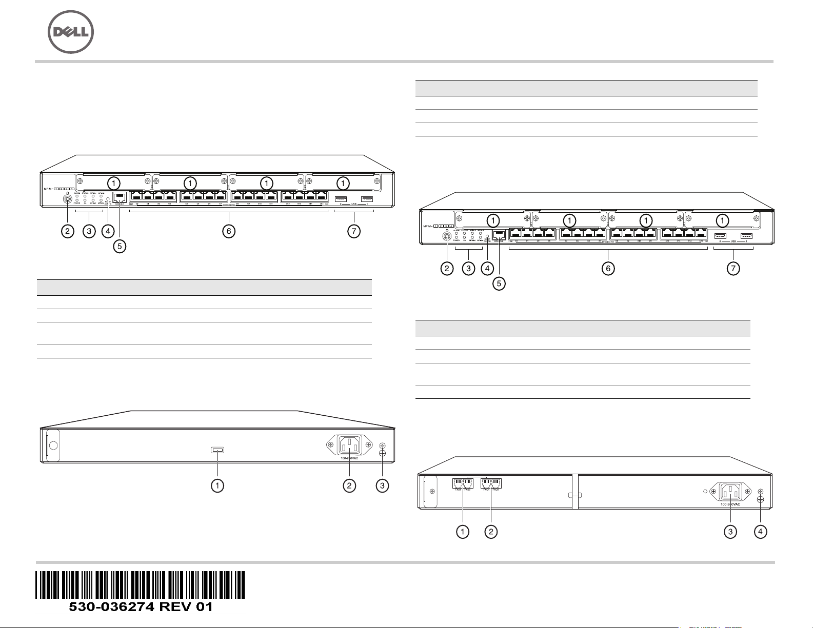
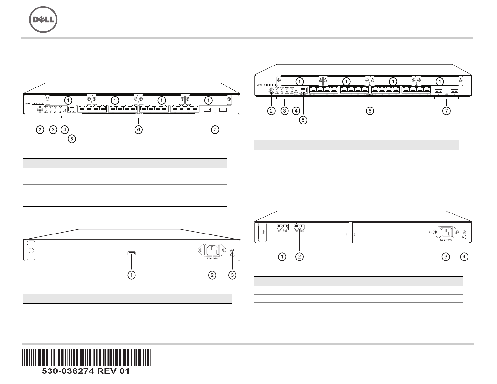
J-SRX240 Services Gateway (J-SRX240B, J-SRX240H) Front Panel
Callout Description Callout Description
1 Mini-PIM slots 5 Console port
2 Power button 6 Gigabit Ethernet (0/0 to 0/15)
3 LEDs (ALARM, POWER,
STATUS, HA, mPIM)
4 Reset Config button
J-SRX240 Services Gateway (J-SRX240B, J-SRX240H, J-SRX240H-POE)
Back Panel
7 USB ports
Callout Description
1 Cable tie holder
2 Power supply input
3 Grounding point
J-SRX240 Services Gateway with Integrated Convergence Services
(J-SRX240H-POE, J-SRX240H-P-MGW) Front Panel
Callout Description Callout Description
1 Mini-PIM slots 5 Console port
2 Power button 6 Gigabit Ethernet (0/0 to 0/15)
3 LEDs (ALARM, POWER,
STATUS, HA, mPIM)
4 Reset Config button
7 USB ports
J-SRX240 Services Gateway with Integrated Convergence Services
(J-SRX240H-P-MGW) Back Panel
Page 2
Callout Description
1 FXS voice port
2 FXO voice port
3 Power supply input
4 Grounding point
J-SRX240 Services Gateway Models
The following four models of J-SRX240 Services Gateway are available:
Device DDR Memory Power over Ethernet Voice Support
J-SRX240B 512 MB No No
J-SRX240H 1 GB No No
J-SRX240H-POE 1 GB Yes No
J-SRX240H-P-MGW 1 GB Yes Yes
Part 2: Connect the Power Cable to the Device
Connect the power cable to the device and a power source. We recommend using a
surge protector. Note the following indications:
POWER LED (green): The device is receiving power.
STATUS LED (green): The device is operating normally.
ALARM LED (amber): The device is operating normally, and may glow amber as a
rescue configuration has not been set. This is not a panic condition.
mPIM LED (off): The Mini-Physical Interface Module (Mini-PIM) is not present or is
not detected by the device. If this LED is green and steadily on, it indicates that the
Mini-PIM is functioning normally.
NOTE:
After a rescue configuration has been set, an amber ALARM LED indicates a
minor alarm, and a solid red ALARM LED indicates that a major problem exists on the
services gateway.
NOTE:
You must allow the device between 5 and 7 minutes to boot up after you have
powered it on. Wait until the STATUS LED is solid green before proceeding to the next
part.
NOTE:
On the J-SRX240H-PoE and J-SRX240H-P-MGW models, Power over Ethernet
(PoE) of 150 watts is supported across all 16 ports (ge-0/0/0 to ge-0/0/15).
Connecting and Configuring the J-SRX240 Services Gateway
Use the instructions below to connect and set up any model of the J-SRX240 Services
Gateway to protect your network. Refer to the LEDs on the front panel of the device to
help you determine the status of the device.
Part 1: Connect the Services Gateway to Earth Ground
1. Obtain a grounding cable—14 AWG single-strand, 4 A—with a ring-type,
vinyl-insulated TV14-6R lug or equivalent attached by a licensed electrician.
2. Connect the grounding cable to a proper earth ground.
3. Place the grounding cable lug over the grounding point on the upper rear of the
chassis, and secure the lug with one 6-32 UNC screw.
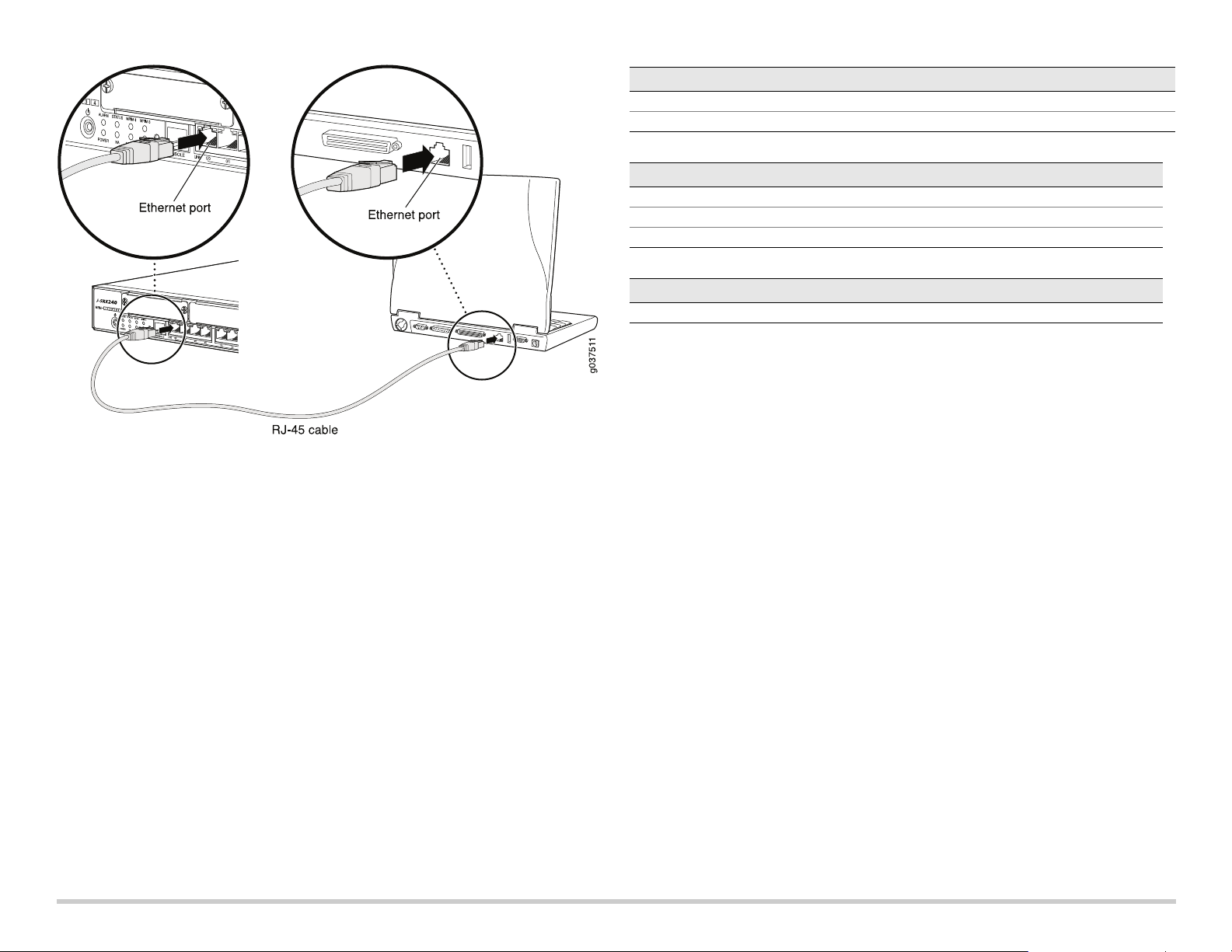
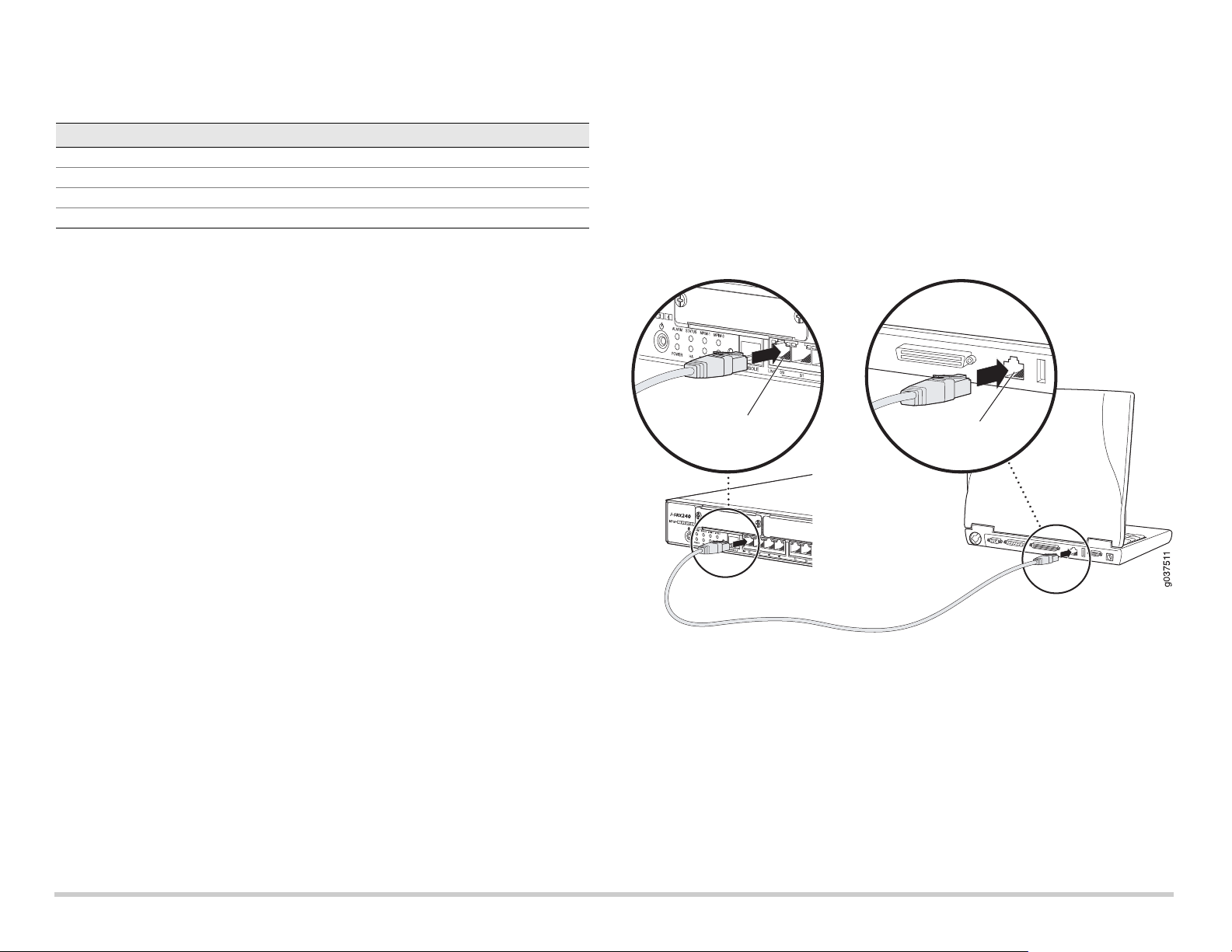
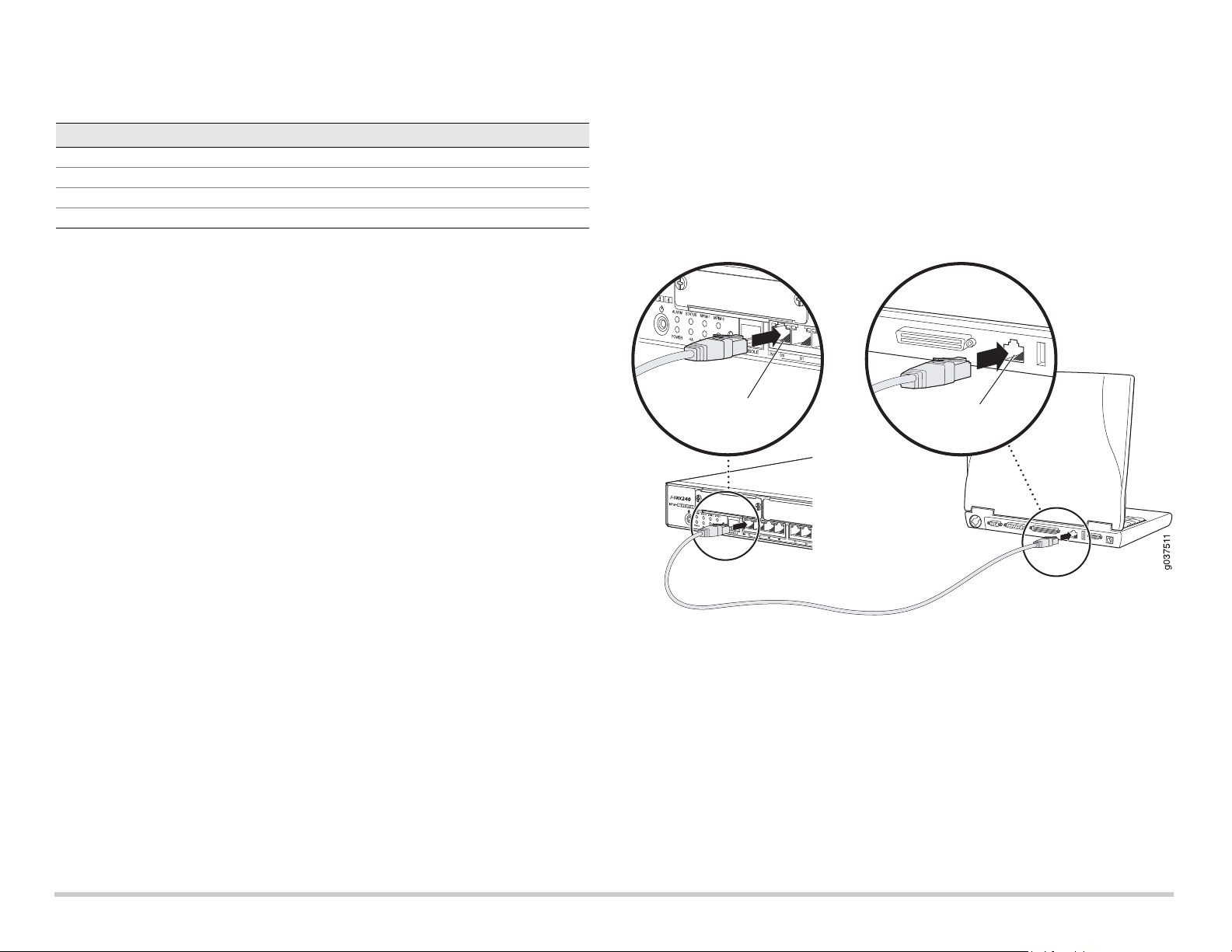
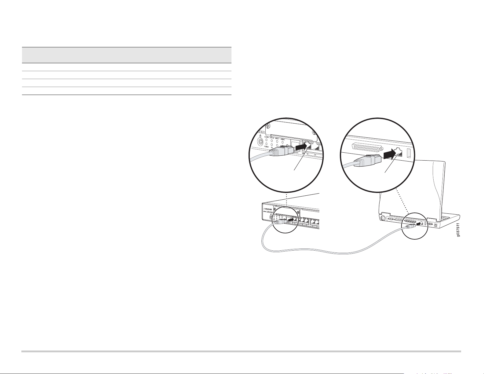
Part 3: Connect the Management Device
Connect the management device to the services gateway using either of the following
methods:
Connect an RJ-45 cable (Ethernet cable) from any one port between ge-0/0/1 and
ge-0/0/15 on the front panel to the Ethernet port on the management device
(workstation or laptop).
We recommend this connection method. If you are using this method to connect,
proceed with Part 4.
Connect an RJ-45 cable (Ethernet cable) from the port labeled CONSOLE to the
supplied DB-9 adapter, which then connects to the serial port on the management
device. (Serial port settings: 9600 8-N-1.)
If you are using this method to connect, proceed with the CLI configuration
instructions available in the Branch SRX Series Services Gateways Golden
Configurations at http://www.juniper.net/us/en/local/pdf/app-notes/3500153-en.pdf.
See the illustration below for details on connecting a management interface:
Page 2
Page 3
Part 4: Understand the Default Configuration Settings
The J-SRX240 Services Gateway is a secure routing device that requires these basic
configuration settings to function properly:
Interfaces must be assigned IP addresses.
Interfaces must be bound to zones.
Policies must be configured between zones to permit/deny traffic.
Source NAT rules must be set.
The device has the following default configuration set when you power it on for the first
time. To be able to use the device, you do not need to perform any initial configuration.
ACTORY DEFAULT SETTINGS FOR INTERFACES
F
Port Label Interface Security Zone DHCP State IP Address
0/0 ge-0/0/0 untrust client unassigned
0/1 to 0/15 ge-0/0/1 to ge-0/0/15 trust server 192.168.1.1/24
FACTORY DEFAULT SETTINGS FOR SECURITY POLICIES
Source Zone Destination Zone Policy Action
trust untrust permit
trust trust permit
untrust trust deny
FACTORY DEFAULT SETTINGS FOR NAT RULE
Source Zone Destination Zone Policy Action
trust untrust source NAT to untrust zone interface
Part 5: Ensure that the Management Device Acquires an IP Address
After connecting the management device to the services gateway, the DHCP server
process on the services gateway will assign an IP address automatically to the
management device. Ensure that the management device acquires an IP address on the
192.168.1/24 subnetwork (other than 192.168.1.1) from the device.
NOTE:
The services gateway functions as a DHCP server and will assign an IP address to
the management device.
If an IP address is not assigned to the management device, manually configure an
IP address in the 192.168.1.0/24 subnetwork. Do not assign the 192.168.1.1 IP
address to the management device, as this IP address is assigned to the device. By
default, the DHCP server is enabled on the L3 VLAN interface, (IRB) vlan.0
(ge-0/0/1 to ge-0/0/15), which is configured with an IP address of 192.168.1.1/24.
When a J-SRX240 Services Gateway is powered on for the first time, it boots using
the factory default configuration.
Part 6: Ensure that an IP Address is Assigned to the Services Gateway
Use one of the following methods to obtain an IP address on the services gateway.
METHOD 1: OBTAINING A DYNAMIC IP ADDRESS ON YOUR SERVICES GATEWAY
Use the ge-0/0/0 port to connect to your Internet Service Provider (ISP). Your ISP
will assign an IP address using the DHCP process.
If you are using this method to obtain an IP address on your services gateway,
proceed with the steps from Part 7 to Part 10 in this document to configure your
device and pass traffic.
Page 3
Page 4
METHOD 2: OBTAINING A STATIC IP ADDRESS ON YOUR SERVICES GATEWAY
Use the ge-0/0/0 port to connect to your ISP. Your ISP will have provided a static IP
address. You will not receive an IP address using the DHCP process.
If you are using this method to obtain an IP address on your services gateway, follow
the instructions from Part 7 to Part 10 in this document.
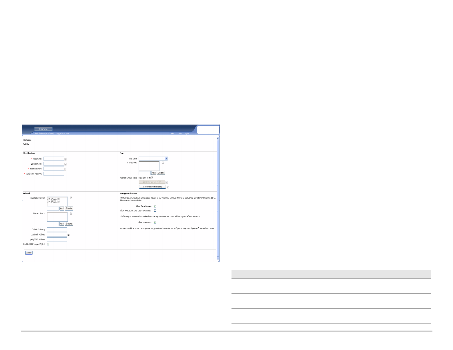
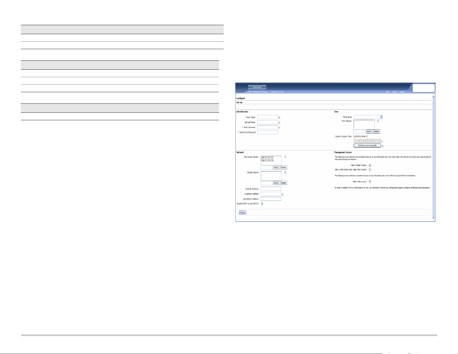
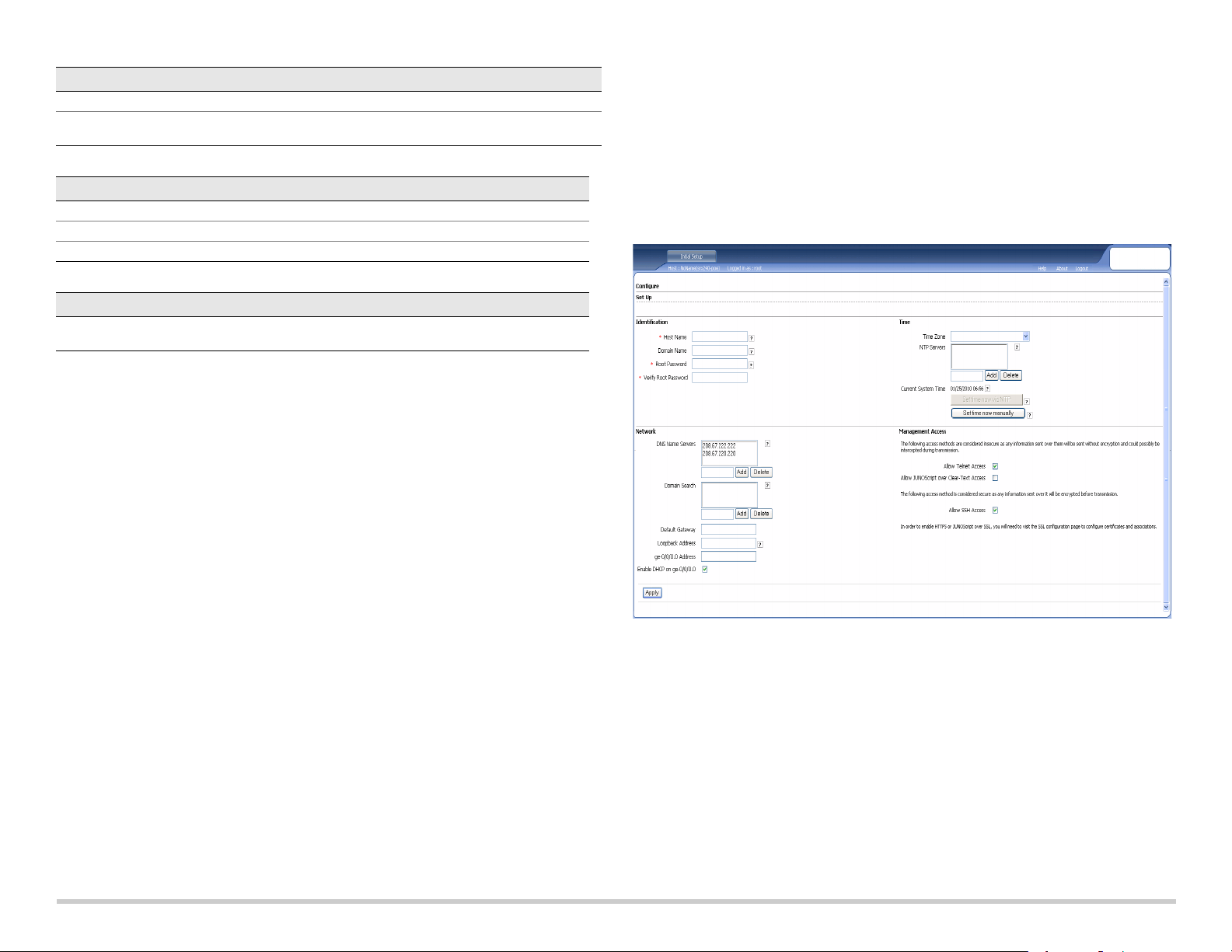
Part 7: Access the J-Web Interface
1. Launch a Web browser on the management device.
2. Enter http://192.168.1.1 in the URL address field. The J-Web login page is
displayed.
3. Specify the default user name as root. Do not enter any value in the Password field.
4. Click Log In. The J-Web Initial Setup page is displayed.
If you have used Method 2 in Part 6 to obtain an IP address on your services gateway,
ensure that you make the following J-Web modifications:
1. Unselect the Enable DHCP on ge-0/0/0.0 check box.
2. Enter the manual IP address provided by your ISP in the ge-0/0/0.0 address field.
The IP address must be entered in the
a.b.c.d/xx
format, where xx is the subnet
mask.
3. Enter the IP address of the gateway in the Default Gateway field. The IP address for
the gateway is also provided by the ISP.
4. Enter server names in the DNS name servers field. The server names will be
provided by your ISP.
5. Apply the configuration.
Part 9: Apply the Basic Configuration
1. Click Commit to save the basic configuration.
2. Click Apply to apply the basic configuration.
NOTE:
To make any changes to the interface configuration, see the Branch SRX Series
Services Gateways Golden Configurations at
http://www.juniper.net/us/en/local/pdf/app-notes/3500153-en.pdf.
Part 10: Verify the Configuration
Access http://www.support.dell.com to ensure that you are connected to the internet.
This connectivity ensures that you can pass traffic through the services gateway.
NOTE:
If the http://www.support.dell.com page does not load, verify your configuration
settings, and ensure that you have applied the configuration.
After you have completed these steps, you can pass traffic from any trust port to the
untrust port.
Part 8: Configure the Basic Settings
Configure the basic settings such as Host Name, Domain Name, and Root Password for
your services gateway.
IMPORTANT:
you apply the configuration.
NOTE:
Ensure that you have configured the IP address and root password before
All fields marked with an asterisk (*) are mandatory.
Connecting and Configuring the J-SRX240 Services Gateway with
Integrated Convergence Services
If you have a J-SRX240H-P-MGW model, use the instructions below to configure voice
support on the media gateway and get started using your device to place and receive
calls.
The following table provides an overview of the steps you must follow to configure voice
support on the media gateway.
Step Ta sk Step Task
1 Connect the FXO and FXS ports. 7 Configure the trunk.
2 Access the J-Web interface. 8 Configure trunk groups.
3 Configure the class of restriction. 9 Create the dial plan.
4 Configure the SIP station. 10 Configure the media gateway.
5 Configure the analog station. 11 Configure the survivable call server.
6 Configure the peer call server.
Page 4
Page 5

Part 1: Connect the FXS and FXO Ports
1. Connect an FXS port (FXS1 or FXS2) on the device to an analog device such as a
telephone, fax, or modem through an RJ-11 cable.
2. Connect an FXO port (FXO1 or FXO2) on the device to the central office (CO)
switches or to a station port on a PSTN through an RJ-11 cable.
3. Connect an Ethernet cable from any of the PoE ports (ge-0/0/0 through ge-0/0/15) to
the VoIP phone.
Part 2: Access the J-Web Interface
1. Launch a Web browser from the management device.
2. Log on using the credentials you set during the initial configuration described in the
“Connecting and Configuring the J-SRX240 Services Gateway” section.
3. The J-Web Dashboard page is displayed.
Part 3: Configure the Class of Restriction
Configure the class of restriction to define the policy dedicated to specifying call type
permissions:
1. Select Configure > Convergence Services > Station > Class of Restriction. The
Class of Restriction Configuration page is displayed.
2. Click Add to create a new class of restriction. The New Class of Restriction page is
displayed.
3. Enter the name in the Class of Restriction field.
4. Click Add to add a new policy to the class of restriction you are creating. The New
Policy Configuration page is displayed.
5. Perform the following actions:
Field Action
Name Specify a name for the station.
Extensions Enter the extension number of the station.
Class of Restriction Select the already configured class of restriction.
Template Name Select the already defined station template.
You can configure the analog templates to be similar so that they can share a common
configuration.
Part 5: Configure the Analog Station
1. Select Configure > Convergence Services > Station. The Station Configuration
page is displayed.
2. Click Add to add the new station and perform the following mandatory basic actions:
Field Action
Name Specify a name for the station.
Extensions Enter the extension number of the station.
Class of Restriction Select the already configured class of restriction.
Template Name Select the already defined station template.
TDM Interface Specify the type of TDM interface to be configured (FXO, FXS, or T1).
NOTE:
You can configure the individual SIP stations similarly so that they can share a
common configuration.
Field Action
Policy Name Specify a name for the policy.
Available Call Types Select the call types applicable to your setup.
Permissions Set permissions (allow or deny) on the selected call types.
NOTE:
By default, only intra-branch calls and emergency calls are allowed.
Part 4: Configure the SIP Station
NOTE:
For initial configuration of the device, you do not need to configure the station
templates. You can use the default values.
1. Select Configure > Convergence Services > Station. The Station Configuration
page is displayed.
2. Click Add to add the new station and perform the following mandatory basic actions:
Part 6: Configure the Peer Call Server
Configure the peer call server that provides call routing and call handling services for the
device:
1. Select Configure > Convergence Services > Call Server. The Peer Call Server
Configuration page is displayed.
2. Perform the following mandatory basic actions:
Field Action
Name Specify the name for the peer call server.
PSTN Access
Number
Address Type Select the address type as either fqdn or ipv4-address.
FQDN Enter the fully qualified domain name.
IP Address Enter the IP address of the peer call server.
NOTE:
When configuring the peer call server:
Specify the external PSTN number for the survivable call server to use if it
must contact the PSTN directly.
Page 5
Page 6
For the device to authenticate itself with the peer call server, you might need to
provide the device user ID and password details as provided by the peer call
server’s administrator.
You can accept the default values in the Port (5060) and Transport (UDP) fields.
For initial configuration of the device, you do not need to specify the codec. The
default set of codecs is used. By default, codecs are specified in the following order:
711-µ, G711-A, G729AB.
Part 7: Configure a Trunk
Configure a trunk for a PSTN time-division multiplexing (TDM) interface to be used by
the device or the survivable call server to route calls to the destination.
1. Select Configure > Convergence Services > Gateway > Trunks. The New Trunk
Configuration page is displayed.
2. Perform the following actions:
Field Action
Trunk Name Enter a name for the trunk.
Trunk Type Select the trunk type (FXO, FXS, or T1).
TDM Interface Select the type of TDM interface to be configured (FXO, FXS, or T1) for
routing certain types of calls.
Part 8: Configure the Trunk Groups
A trunk group comprises multiple trunks specified in the order of precedence in which
they must be selected to route a call.
1. Select Configure > Convergence Services > Gateway > Trunk Groups. The
Trunk Group Configuration page is displayed.
2. Click Add to create a new trunk group and perform the following mandatory actions:
3. Enter a name in the Dial Plan Name field and click Add. The New Route Pattern
Configuration page displays.
4. Perform the following mandatory basic actions:
Field Action
Route Pattern Specify the route pattern name.
Call Type Select the call type. The default is trunk-call.
Trunk-groups Select the preconfigured trunk groups to include in the route pattern.
NOTE:
You can accept the default values for the Preference and Digit Manipulation fields.
Part 10: Configure the Media Gateway
Configure the media gateway to enable users to place calls within the branch and
externally when the peer call server is accessible to provide call routing and other call
handling services:
1. Select Configure > Convergence Services > Media Gateway > Gateway. The
Media Gateway Configuration page is displayed.
2. Click Add and enter the following mandatory settings:
Field Action
Media Gateway Specify the device name.
Call Server Select a peer call with which to associate.
Dial Plan Select a preconfigured dial plan.
Zone Specify the service point for the device’s zone to enable the media gateway
NOTE:
You can accept the default values in the Port (5060) and Transport (UDP) fields.
and survivable call server services for the specified zone.
Field Action
Name Specify a name for the trunk group.
Available Trunks Select the trunks applicable to your setup.
Part 9: Create the Dial Plan
Create the dial plan to enable the peer call server to route outbound calls placed from
SIP telephones/analog stations at the branch to its PSTN:
1. Select Configure > Convergence Services > Dial Plan and click on Dial Plan. The
Dial Plan Configuration page is displayed.
2. Click Add to create a new dial plan. The New Dial Plan Configuration page is
displayed.
Page 6
Page 7
Part 11: Configure the Survivable Call Server
This server assumes the responsibilities of the peer call server when the peer call server
is unreachable:
1. Select Configure > Convergence Services > Call Service. The Survivable Call
Service page is displayed.
2. Click Add to create a new call service and perform the following mandatory basic
actions:
Field Action
Call Service Name Specify the name for the call service.
Call Server Select the peer call server name.
Dial Plan Select the preconfigured dial plan to be used for the survivable call server.
Zone Specify the name for the zone.
NOTE:
All other parameters required to configure the call service are optional and you
can accept the default values set for these parameters.
Powering Off the Device
You can power off the device in one of the following ways:
Graceful shutdown—Press and immediately release the Power button. The device
begins gracefully shutting down the operating system.
Immediate shutdown—Press the Power button and hold it for 10 seconds. The
device immediately shuts down. Press the Power button again to power on the
device.
NOTE:
You can reboot or halt the system in the J-Web interface by selecting
Maintain > Reboot.
For additional configuration information, see the Branch SRX Series Services Gateways
Golden Configurations at
http://www.juniper.net/us/en/local/pdf/app-notes/3500153-en.pdf.
For detailed software configuration information, see the software documentation
available at http://www.juniper.net/techpubs/software/junos-srx/index.html.
Contacting Dell
For technical support, see http://www.support.dell.com.
Information in this document is subject to change without notice. All rights reserved. Reproduction of these materials in any manner whatsoever without the written permission of Juniper Networks is strictly forbidden. Trademarks used
in this text: Dell™, the DELL™ logo, and PowerConnect™ are trademarks of Dell Inc. Juniper Networks® and G33® are registered trademarks of Juniper Networks, Inc. in the United States and other countries. All other trademarks,
service marks, registered trademarks, or registered service marks are the property of their respective owners. Juniper Networks assumes no responsibility for any inaccuracies in this document. Juniper Networks reserves the right to
change, modify, transfer, or otherwise revise this publication without notice. Products made or sold by Juniper Networks or components thereof might be covered by one or more of the following patents that are owned by or licensed to
Juniper Networks: U.S. Patent Nos. 5,473,599, 5,905,725, 5,909,440, 6,192,051, 6,333,650, 6,359,479, 6,406,312, 6,429,706, 6,459,579, 6,493,347, 6,538,518, 6,538,899, 6,552,918, 6,567,902, 6,578,186, and 6,590,785. Copyright ©
2010, Juniper Networks, Inc. All rights reserved. Printed in USA. Part Number: 530-036274 REV 01, July 2010.
Page 8

037502
g037518
Dell PowerConnect J-Series J-SRX240 服務閘道快速入門
使用此快速入門中的說明,協助您將 Dell PowerConnect J-Series J-SRX240 服務閘道連
線至網路。如需詳細資訊,請參閱 J-SRX240 Services Gateway Hardware Guide,網址
為 http://support.dell.com/manuals。(
J-SRX240 Services Gateway (J-SRX240B、J-SRX240H)
編號 說明 編號 說明
1
2
3
4
J-SRX240
Mini-PIM 插槽
Power 按鈕
LED (ALARM、POWER、
STATUS、HA、mPIM)
Reset Config 按鈕
服務閘道
(J-SRX240B、J-SRX240H、J-SRX240H-POE)
管理型號為
5
6
7
SRX240)
前面板
主控台連接埠
十億位元乙太網路 (0/0 到 0/15)
USB 連接埠
後面板
含整合收斂服務之
J-SRX240H-P-MGW)
編號 說明 編號 說明
1
2
3
4
Mini-PIM 插槽
Power 按鈕
LED (ALARM、POWER、
STATUS、HA、mPIM)
Reset Config 按鈕
含整合收斂服務之
J-SRX240
前面板
J-SRX240
服務閘道
5
6
7
服務閘道
(J-SRX240H-POE
主控台連接埠
十億位元乙太網路 (0/0 到 0/15)
USB 連接埠
(J-SRX240H-P-MGW)
、
後面板
編號 說明
1
2
3
纜線束固定器
電源供應輸入
接地點
編號 說明
1
2
3
4
FXS 語音連接埠
FXO 語音連接埠
電源供應輸入
接地點
Page 9
J-SRX240 服務閘道機型
⮹偁恾抲㘴⩯
⮹偁恾抲㘴⩯
5-儫偩
提供以下四種 J-SRX240 服務閘道機型:
裝置 DDR 記憶體 乙太網路供電 語音支援
J-SRX240B 512 MB
J-SRX240H 1 GB
J-SRX240H-POE 1 GB
J-SRX240H-P-MGW 1 GB
請注意
:
在 J-SRX240H-PoE 與 J-SRX240H-P-MGW 機型上,全部 16 個連接埠 (ge-0/0/0
否否
否否
是否
是是
到 ge-0/0/15) 皆支援 150 瓦的乙太網路供電 (PoE)。
連接與組態 J-SRX240 服務閘道
使用下列說明來連接及設定任何機型的 J-SRX240 服務閘道,以保護您的網路。請參考
裝置前面板上的 LED,以協助您確定裝置的狀態。
第
1
部分:將服務閘道連接至地面
1. 取得一條接地纜線 (14 AWG 單股,4 A),並由授權的電工將纜線與圓形乙烯基絕緣
TV14-6R 接線片或同型接線片連接。
2. 將接地纜線連接到正確的接地點。
3. 將接地纜線接線片置於機箱背面上方的接地點,然後使用一個 6-32 UNC 螺絲來固定
接線片。
用 RJ-45 纜線 ( 乙太網路纜線 ) 將前面板上 ge-0/0/1 到 ge-0/0/15 之間的任何一個連
接埠與管理裝置 ( 工作站或筆記型電腦 ) 上的乙太網路連接埠連在一起。
我們建議您使用這種連接方法。如果使用此方法進行連接,請繼續第 4 部分。
用 RJ-45 纜線 ( 乙太網路纜線 ) 將標有 CONSOLE 的連接埠與隨附的 DB-9 配接卡相
連,然後將其連接至管理裝置上的序列連接埠。( 序列連接埠設定:9600 8-N-1。)
如果您使用此方法進行連接,請參閱 Branch SRX Series Services Gateways
Golden Configurations ( 網址為
http://www.juniper.net/us/en/local/pdf/app-notes/3500153-en.pdf) 中的 CLI 組態說明
繼續操作。
如需連接管理介面的詳細資訊,請參閱下圖 :
第
2
部分:將電源纜線連接至裝置
將電源纜線連接至裝置與電源。我們建議您使用突波保護器。請注意下列指示:
POWER LED ( 綠色 ):裝置已通電。
STATUS LED ( 綠色):裝置運作正常。
ALARM LED ( 琥珀黃色 ):裝置運作正常,此外若未設定救援組態,則可能會亮起琥
珀黃色燈。這並不屬於緊急情況。
mPIM LED ( 熄滅 ):Mini-Physical Interface Module (Mini-PIM) 不存在,或裝置未偵測
到。如果此 LED 為綠色且恆亮,表示 Mini-PIM 功能正常。
請注意
:
設定完救援組態後,琥珀黃色 ALARM LED 表示輕微警示,而紅色 ALARM LED
表示服務閘道存在嚴重問題。
請注意
:
在開啟裝置電源後,必須讓裝置有 5 到 7 分鐘的啟動時間。請靜待 STATUS LED
穩定亮起綠燈,然後再繼續下一個部分。
第
3
部分:連接管理裝置
使用以下其中一種方法將管理裝置連接至服務閘道:
第
4
部分:瞭解預設組態設定
J-SRX240 服務閘道是一個安全路由裝置,其需要這些基本組態設定才能正常運作 :
必須為介面指派 IP 位址。
必須將介面連接至區域。
必須在區域間組態政策,以允許 / 拒絕通訊流量。
必須設定來源 NAT 規則。
第一次開啟裝置電源時,會設定下列預設組態。您不必執行任何初始組態便可使用裝置。
第 2 頁
Page 10

介面的出廠預設設定
連接埠標籤 介面 安全區 DHCP 狀態 IP 位址
0/0 ge-0/0/0 untrust
0/1 到 0/15 ge-0/0/1 到 ge-0/0/15
trust
用戶端 未指派
伺服器
192.168.1.1/24
安全性政策的出廠預設設定
來源區 目的區 政策動作
trust untrust
trust trust
untrust trust
NAT
規則的出廠預設設定
來源區 目的區 政策動作
trust untrust
第
5
部分:確保管理裝置取得
IP
位址
來源 NAT 到 untrust 區域介面
允許
允許
拒絕
將管理裝置連接至服務閘道後,服務閘道上的 DHCP 伺服器程序會將 IP 位址自動指派給
管理裝置。確保管理裝置從裝置取得 192.168.1/24 子網路 ( 而不是 192.168.1.1) 上的 IP
位址。
請注意
:
服務閘道的功能類似於 DHCP 伺服器,而且會為管理裝置指派 IP 位址。
如果未將 IP 位址指派給管理裝置,請手動組態 192.168.1.0/24 子網路中的一個 IP
位址。請勿將 192.168.1.1 IP 位址指派給管理裝置,因為此 IP 位址已指派給裝置。
依預設,DHCP 伺服器在 L3 VLAN 介面,即 (IRB) vlan.0 (ge-0/0/1 到 ge-0/0/15) 啟
用,它透過 IP 位址 192.168.1.1/24 組態。
第一次開啟 J-SRX240 服務閘道電源時,其會使用出廠預設組態啟動。
如果您使用此方法取得服務閘道的 IP 位址,請遵循本文件中第 7 到第 10 部分的
指示。
第
7
部分:存取
J-Web
介面
1. 在管理裝置上啟動 Web 瀏覽器。
2. 在 URL 位址欄位中輸入 http://192.168.1.1。接著會顯示 J-Web 登入頁面。
3. 將預設使用者名稱指定為 root。請勿在 Password 欄位中輸入任何值。
4. 按一下 Log In。會顯示 J-Web Initial Setup 頁面。
第
6
部分:確認已將
IP
位址指派給服務閘道
使用以下其中一種方法取得服務閘道的 IP 位址。
方法 1:取得服務閘道的動態
IP
位址
使用 ge-0/0/0 連接埠連線至「網際網路服務供應商」(ISP)。ISP 會使用 DHCP 程序
指派一個 IP 位址。
如果您使用此方法取得服務閘道的 IP 位址,請繼續執行本文件中第 7 到第 10 部分
的步驟,以設定您的裝置及傳送通訊流量。
方法 2:取得服務閘道的靜態
IP
位址
使用 ge-0/0/0 連接埠連線至 ISP。ISP 將提供一個靜態 IP 位址。將不會接收到使用
DHCP 程序指派的 IP 位址。
第
8
部分:進行基本設定
為服務閘道組態基本設定,例如 Host Name、Domain Name 與 Root Password。
重要
:
確認您在套用組態之前,已設定 IP 位址與根密碼。
請注意
:
標記星號 (*) 的所有欄位皆為必填欄位。
如果您已使用第 6 部分的方法 2 取得服務閘道的 IP 位址,請務必修改下列的 J-Web
內容:
1. 取消選擇 Enable DHCP on ge-0/0/0.0 核取方塊。
2. 在 ge-0/0/0.0 位址欄位中輸入 ISP 提供給您的手動 IP 位址。必須以
a.b.c.d/xx
的格式
輸入此 IP 位址,其中 xx 是子網路遮罩。
3. 在 Default Gateway 欄位中輸入閘道的 IP 位址。閘道的 IP 位址也由 ISP 提供。
菴 3 珜
Page 11

4. 在 DNS name servers 欄位中輸入伺服器名稱。伺服器名稱由您的 ISP 提供。
5. 套用組態。
第
9
部分:套用基本組態
1. 按一下 Commit 來儲存基本組態。
2. 按一下 Apply 來套用基本組態。
請注意
:
若要對介面組態進行任何變更,請參閱 Branch SRX Series Services Gateways
Golden Configurations,網址為
http://www.juniper.net/us/en/local/pdf/app-notes/3500153-en.pdf。
第
10
部分:驗證組態
存取 http://www.support.dell.com,以確保您已連線至網際網路。此連線可確保您可以透
過服務閘道傳送通訊流量。
請注意
:
如果 http://www.support.dell.com 頁面未載入,請驗證組態設定,並確保您已套用
該組態。
完成這些步驟後,您可以將通訊流量從任何 trust 連接埠傳送至 untrust 連接埠。
連接與組態含整合收斂服務的 J-SRX240 服務閘道
如果您擁有 J-SRX240H-P-MGW 機型,請使用下列指示組態媒體閘道的語音支援,並開
始使用您的裝置來撥打與接聽電話。
下表概述了在組態媒體閘道的語音支援時,您必須遵循的步驟。
步驟 工作 步驟 工作
1
連接 FXO 與 FXS 連接埠。
2
存取 J-Web 介面。
3
組態限制類別。
4
組態 SIP 工作站。
5
組態類比工作站。
6
組態對等呼叫伺服器。
第
1
部分:連接
FXS 與 FXO
連接埠
1. 透過 RJ-11 纜線將裝置上的 FXS 連接埠 (FXS1 或 FXS2) 連接至類比裝置,例如電
話、傳真或數據機。
2. 透過 RJ-11 纜線將裝置上的 FXO 連接埠 (FXO1 或 FXO2) 連接至總公司 (CO) 交換
機,或 PSTN 上的工作站連接埠。
3. 透過乙太網路纜線將任一 PoE 連接埠 (ge-0/0/0 到 ge-0/0/15) 連接至 VoIP 電話。
第
2
部分:存取
J-Web
介面
1. 從管理裝置啟動 Web 瀏覽器。
7
組態中繼。
8
組態中繼群組。
9
建立撥號對應表。
10
組態媒體閘道。
11
組態可長期有效的呼叫伺服器。
2. 使用您在初始組態期間設定的驗證資料來登入,如 「連接與組態 J-SRX240 服務閘
道」一節中所述。
3. 會顯示 J-Web Dashboard 頁面。
第
3
部分:組態限制類別
組態限制類別,以定義專用於指定呼叫類型權限的政策 :
1. 選擇 Configure > Convergence Services > Station > Class of Restriction。會顯
示 Class of Restriction Configuration 頁面。
2. 按一下 Add,建立新的限制類別。會顯示 New Class of Restriction 頁面。
3. 在 Class of Restriction 欄位中,輸入名稱。
4. 按一下 Add,將新政策新增至您要建立的限制類別中。會顯示 New Policy
Configuration 頁面。
5. 執行下列動作 :
欄位 動作
Policy Name
Available Call Types
Permissions
請注意
:
依預設,僅允許分公司內部的呼叫與緊急呼叫。
第
4
部分:組態
請注意
:
針對裝置的初始組態,您不必組態工作站範本。您可以使用預設值。
SIP
工作站
為政策指定名稱。
選擇適用於您的設定的呼叫類型。
設定所選呼叫類型的權限 ( 允許或拒絕 )。
1. 選擇 Configure > Convergence Services > Station。會顯示 Station Configuration
頁面。
2. 按一下 Add,新增工作站並執行下列必需的基本動作 :
欄位 動作
Name
Extensions
Class of Restriction
Template Name
為工作站指定名稱。
輸入工作站的分機號碼。
選擇已組態的限制類別。
選擇已定義的工作站範本。
您可以將類比範本組態為類似範本,以便其能夠共享通用的組態。
第
5
部分:組態類比工作站
1. 選擇 Configure > Convergence Services > Station。會顯示 Station Configuration
頁面。
2. 按一下 Add,新增工作站並執行下列必需的基本動作 :
菴 4 珜
Page 12

欄位 動作
Name
Extensions
Class of Restriction
Template Name
TDM Interface
請注意
:
您可以使用類似方式組態個別 SIP 工作站,以便其能夠共享通用的組態。
第
6
部分:組態對等呼叫伺服器
為工作站指定名稱。
輸入工作站的分機號碼。
選擇已組態的限制類別。
選擇已定義的工作站範本。
指定要組態的 TDM 介面類型 (FXO、FXS 或 T1)。
組態為裝置提供呼叫路由與呼叫處理服務的對等呼叫伺服器 :
1. 選擇 Configure > Convergence Services > Call Server。會顯示 Peer Call Server
Configuration 頁面。
2. 執行下列必需的基本動作 :
欄位 動作
Trunk Name
Trunk Type
TDM Interface
第
8
部分:組態中繼群組
輸入中繼名稱。
選擇中繼類型 (FXO、FXS 或 T1)。
選擇要組態的 TDM 介面類型 (FXO、FXS 或 T1),以路由特定類型的呼叫。
中繼群組由多個中繼組成,這些中繼將依照其在路由呼叫時必須遵循的優先順序來指定。
1. 選擇 Configure > Convergence Services > Gateway > Trunk Groups。會顯示
Trunk Group Configuration 頁面。
2. 按一下 Add,建立新的中繼群組並執行下列必需動作 :
欄位 動作
Name
Available Trunks
為中繼群組指定名稱。
選擇適用於設定的中繼。
欄位 動作
Name
PSTN Access
Number
Address Type
FQDN
IP Address
請注意
:
組態對等呼叫伺服器時 :
針對要使用對等呼叫伺服器來驗證其自身的裝置,您可能需要提供對等呼叫伺服器的
為對等呼叫伺服器指定名稱。
為要使用的長期有效的呼叫伺服器指定外部 PSTN 號碼 ( 若其必須直接聯
絡 PSTN)。
選擇位址類型作為 fqdn 或 ipv4-address。
輸入完全合格的網域名稱。
輸入對等呼叫伺服器的 IP 位址。
管理員所提供的裝置使用者 ID 與密碼詳細資訊。
您可以接受 Port (5060) 與 Transport (UDP) 欄位中的預設值。
針對裝置的初始組態,您不必指定轉碼器。會使用預設的轉碼器集合。依預設,會透
過下列順序來指定轉碼器 :711-µ、G711-A、G729AB。
第
7
部分:組態中繼
為裝置或長期有效的呼叫伺服器要使用的 PSTN 分時多工法 (TDM) 介面組態中繼,以將
呼叫路由至目的地。
1. 選擇 Configure > Convergence Services > Gateway > Trunks。會顯示 New
Trunk Configuration 頁面。
2. 執行下列動作 :
第
9
部分:建立撥號對應表
建立撥號對應表,使對等呼叫伺服器將分公司的 SIP 電話 / 類比工作站撥打的外線電話路
由至其 PSTN:
1. 選擇 Configure > Convergence Services > Dial Plan,然後按一下 Dial Plan。會
顯示 Dial Plan Configuration 頁面。
2. 按一下 Add,建立新的撥號對應表。會顯示 New Dial Plan Configuration 頁面。
3. 在 Dial Plan Name 欄位中輸入名稱,然後按一下 Add。會顯示 New Route Pattern
Configuration 頁面。
4. 執行下列必需的基本動作 :
欄位 動作
Route Pattern
Call Type
Trunk-groups
請注意
:
您可以接受 Preference 與 Digit Manipulation 欄位的預設值。
第
10
部分:組態媒體閘道
指定路由模式名稱。
選擇呼叫類型。預設為中繼呼叫。
選擇要包括在路由模式中的預先組態的中繼群組。
在可以存取對等呼叫伺服器來提供呼叫路由及其他呼叫處理服務的情況下,組態媒體閘
道,讓使用者可以在分公司內部或外部撥打電話 :
1. 選擇 Configure > Convergence Services > Media Gateway > Gateway。會顯示
Media Gateway Configuration 頁面。
2. 按一下 Add,然後輸入下列必需設定 :
第 5 頁
Page 13
欄位 動作
Media Gateway
Call Server
Dial Plan
Zone
請注意
:
您可以接受 Port (5060) 與 Transport (UDP) 欄位中的預設值。
第
11
部分:組態長期有效的呼叫伺服器
指定裝置名稱。
選擇要關聯的對等呼叫伺服器。
選擇預先組態的撥號對應表。
為裝置的區域指定服務點,以啟用指定區域的媒體閘道與長期有效的呼叫伺服
器服務。
無法連線對等呼叫伺服器時,此伺服器會接手對等呼叫伺服器的工作 :
1. 選擇 Configure > Convergence Services > Call Service。會顯示 Survivable Call
Service 頁面。
2. 按一下 Add,建立新的呼叫服務並執行下列必需的基本動作 :
欄位 動作
Call Service Name
Call Server
Dial Plan
Zone
請注意
:
組態呼叫服務所需的其他所有參數都是可選參數,您可以接受為這些參數設定的
為呼叫服務指定名稱。
選擇對等呼叫伺服器的名稱。
選擇要用於長期有效的呼叫伺服器之預先組態的撥號對應表。
為區域指定名稱。
預設值。
聯絡 Dell
如需技術支援,請參閱 http://www.support.dell.com。
關閉裝置電源
您可以使用下列方式之一來關閉裝置電源 :
平穩關閉 - 按下並立即鬆開 Power。裝置會開始平穩關閉作業系統。
立即關閉 - 按住 Power 10 秒鐘。裝置會立即關閉。再次按下 Power 可開啟裝置電源。
請注意
:
透過選擇 Maintain > Reboot,您可以在 J-Web 介面中重新啟動或暫停系統。
如需其他組態資訊,請參閱 Branch SRX Series Services Gateways Golden
Configurations,網址為
http://www.juniper.net/us/en/local/pdf/app-notes/3500153-en.pdf。
如需詳細的軟體組態資訊,請參閱軟體文件,網址
http://www.juniper.net/techpubs/software/junos-srx/index.html。
本文件中的資訊如有變更,恕不另行通知。保留所有權利。未經 Juniper Networks 書面許可,嚴格禁止以任何方式複製這些資料。本文中所使用的商標:Dell™、DELL™ 標誌和 PowerConnect™ 為 Dell Inc. 的商標。Juniper
Networks® 和 G33® 為 Juniper Networks, Inc. 在美國與其他國家 / 地區的註冊商標。所有其他商標、服務標記、註冊商標或註冊服務標記都屬於其個別擁有者的財產。Juniper Networks 對本文件中的任何錯誤,不承擔任何責任。
Juniper Networks 保留對本出版物進行變更、修改、轉印或其他修訂而不另行通知的權利。Juniper Networks 製造或銷售的產品或其中的元件可能涵蓋於下列一或多個由 Juniper Networks 所有或 Juniper Networks 已獲授權的專利:美
國專利號 5,473,599、5,905,725、5,909,440、6,192,051、6,333,650、6,359,479、6,406,312、6,429,706、6,459,579、6,493,347、6,538,518、6,538,899、6,552,918、6,567,902、6,578,186 及 6,590,785。版權所有 © 2010,
Juniper Networks, Inc. 保留所有權利。美國印刷。產品編號:530-036274-ZH-HANT 修訂本 01,2010 年 7 月
菴 6 珜
Page 14
037502
g037518
Dell PowerConnect J 系列 J-SRX240 服务网关快速入门
按照本快速入门中的说明进行操作,即可帮助您将 Dell PowerConnect J 系列 J-SRX240
服务网关连接到网络。有关详细信息,请参阅 J-SRX240 Services Gateway Hardware
Guide,网址:http://support.dell.com/manuals。
J-SRX240
编号 说明 编号 说明
1
2
3
4
J-SRX240
服务网关
小型 PIM 插槽
Power 按钮
LED (ALARM、 POWER、
STATUS、 HA 和 mPIM)
Reset Config 按钮
服务网关
(J-SRX240B、J-SRX240H)
(J-SRX240B、J-SRX240H、J-SRX240H-POE)
5
6
7
(规范型号
SRX240
)
前面板
控制台端口
千兆位以太网 (0/0 至 0/15)
USB 端口
后面板
集成融合服务的
J-SRX240H-P-MGW)
编号 说明 编号 说明
1
2
3
4
集成融合服务的
J-SRX240
服务网关
前面板
小型 PIM 插槽
Power 按钮
LED (ALARM、 POWER、
STATUS、 HA 和 mPIM)
Reset Config 按钮
J-SRX240
服务网关
(J-SRX240H-POE
5
6
7
控制台端口
千兆位以太网 (0/0 至 0/15)
USB 端口
(J-SRX240H-P-MGW)
、
后面板
编号 说明
1
2
3
电缆固定夹
电源输入
接地点
编号 说明
1
2
3
4
FXS 语音端口
FXO 语音端口
电源输入
接地点
Page 15
J-SRX240 服务网关型号
ⅴ⮹几䵾♲
ⅴ⮹几䵾♲
5-䟄冕
提供以下四种型号的 J-SRX240 服务网关:
设备 DDR 内存 以太网供电 语音支持
J-SRX240B 512 MB
J-SRX240H 1 GB
J-SRX240H-POE 1 GB
J-SRX240H-P-MGW 1 GB
否否
否否
是否
是是
注意: 对于 J-SRX240H-PoE 和 J-SRX240H-P-MGW 型号,所有 16 个端口 (ge-0/0/0
至 ge-0/0/15)均支持 150W 以太网供电 (PoE)。
连接和配置 J-SRX240 服务网关
按照下面的说明连接和设置任何型号的 J-SRX240 服务网关以保护网络。参照设备前面
板上的 LED 来帮助您确定设备的状态。
第
1
部分:将服务网关接地
1. 获取接地电缆—14 AWG 单线, 4 A—带环状、乙烯绝缘 TV14-6R 接线片或同等电
缆,由授权电工接线。
2. 将接地电缆适当接地。
3. 将接地电缆接线片置于机箱背面上方的接地点,然后使用一个 6-32 UNC 螺钉来固定
接线片。
将 RJ-45 电缆(以太网电缆) 从前面板上 ge-0/0/1 至 ge-0/0/15 中的任一端口连接到管
理设备 ( 工作站或便携式计算机 ) 上的以太网端口。
我们建议采用这种连接方法。如果您使用此方法进行连接,请继续第 4 部分。
将 RJ-45 电缆(以太网电缆 )从标有 CONSOLE 的端口连接到提供的 DB-9 适配器,然
后将其连接到管理设备上的串行端口。(串行端口设置:9600 8-N-1。)
如果使用此方法进行连接,请继续执行 Branch SRX Series Services Gateways
Golden Configurations 中提供的 CLI 配置说明,该文档的网址为
http://www.juniper.net/us/en/local/pdf/app-notes/3500153-en.pdf。
有关连接管理接口的详细信息,请参阅下图:
第
2
部分:将电源线连接到设备
将电源线连接到设备和电源。我们建议使用电涌保护器。请注意以下指示 :
POWER LED ( 绿色 ):设备通电。
STATUS LED ( 绿色 ):设备正常工作。
ALARM LED ( 琥珀黄色 ):设备正常工作,但可能由于未设置救援配置而发出琥珀色
黄光。这并不是紧急情况。
mPIM LED (关闭):小型物理接口模块 (Mini-PIM) 不存在或没有被设备检测到。如
果该 LED 为绿色常亮,则表示 Mini-PIM 工作正常。
注意: 设置完救援配置后,琥珀黄色的 ALARM LED 表示不严重的警告,而红色常亮的
ALARM LED 表示服务网关存在严重问题。
注意: 接通电源后,必须等待 5 至 7 分钟的设备启动时间。请等待至 STATUS LED 变为
绿色常亮,再执行下一部分。
第
3
部分:连接管理设备
使用以下任一方法将管理设备连接到服务网关:
第
4
部分:了解缺省配置设置
J-SRX240 服务网关是需要进行以下基本配置设置才能正常运行的安全路由设备:
必须为接口分配 IP 地址。
必须将接口绑定到区段。
必须配置区段间的策略以允许 / 拒绝信息流。
必须设置源 NAT 规则。
首次接通电源时,设备已设置以下缺省配置。无需进行任何初始配置即可使用设备。
第 2 页
Page 16
接口的出厂缺省设置
端口标签 接口 安全区段 DHCP 状态 IP 地址
0/0 ge-0/0/0 untrust
0/1 至 0/15 ge-0/0/1 至 ge-0/0/15
trust
客户端 未指派
服务器
192.168.1.1/24
安全策略的出厂缺省设置
源区段 目的区段 策略动作
trust untrust
trust trust
untrust trust
NAT
规则的出厂缺省设置
源区段 目的区段 策略动作
trust untrust
第
5
部分:确保管理设备获得
将管理设备连接到服务网关后,服务网关上的 DHCP 服务器进程会自动为管理设备分配
一个 IP 地址。确保管理设备能从该设备获得 192.168.1/24 子网 (而不是 192.168.1.1)
上的 IP 地址。
注意:
服务网关起着 DHCP 服务器的作用,将会给管理设备分配 IP 地址。
如果未给管理设备分配 IP 地址,请手动配置 192.168.1.0/24 子网中的 IP 地址。不
要给管理设备分配 192.168.1.1 IP 地址,因为此 IP 地址已分配给该设备。缺省情况
下, DHCP 服务器在 L3 VLAN 接口 (IRB) vlan.0 (ge-0/0/1 至 ge-0/0/15) 上处于启用
状态,该接口的 IP 地址配置为 192.168.1.1/24。
首次接通 J-SRX240 服务网关的电源时,其会使用出厂缺省配置启动。
IP
地址
源 NAT 到 untrust 区段接口
允许
允许
拒绝
如果您使用此方法获得服务网关的 IP 地址,请按照本文档第 7 部分至第 10 部分中
的说明进行操作。
第
7
部分:访问
1. 在管理设备上启动 Web 浏览器。
2. 在 URL 地址字段中输入 http://192.168.1.1。将显示 J-Web 登录页面。
3. 指定缺省用户名为 root。不要在 Password 字段中输入任何值。
4. 单击 Log In。将显示 J-Web Initial Setup 页面。
J-Web
界面
第
6
部分:确保已将
使用以下方法之一在服务网关上获得 IP 地址。
方法 1:在服务网关上获取动态
使用 ge-0/0/0 端口连接到互联网服务提供商 (ISP)。ISP 将使用 DHCP 进程分配一个
IP 地址。
如果您使用此方法获得服务网关的 IP 地址,请继续本文档第 7 部分至第 10 部分中
的步骤来配置设备和传送信息流。
方法 2:在服务网关上获得静态
使用 ge-0/0/0 端口连接到 ISP。 ISP 将提供一个静态 IP 地址。使用 DHCP 进程不会
收到 IP 地址。
IP
地址分配给服务网关
IP
地址
IP
地址
第
8
部分:配置基本设置
配置服务网关的基本设置, Host Name, Domain Name 和 Root Password。
重要: 确保在应用配置之前已配置了 IP 地址和根密码。
注意: 所有标有星号 (*) 的字段均为必填字段。
如果您已使用第 6 部分中的方法 2 获取服务网关的 IP 地址,请确保进行以下 J-Web
修改:
1. 取消选中 Enable DHCP on ge-0/0/0.0 复选框。
2. 在 ge-0/0/0.0 地址字段中输入 ISP 提供的手动 IP 地址。必须以
IP 地址,其中 xx 为子网掩码。
3. 在 Default Gateway 字段中输入网关的 IP 地址。网关的 IP 地址同样由 ISP 提供。
a.b.c.d/xx
的格式输入
第 3 页
Page 17

4. 在 DNS name servers 字段中输入服务器名称。服务器名称将由 ISP 提供。
5. 应用配置。
第
9
部分:应用基本配置
1. 单击 Commit 保存基本配置。
2. 单击 Apply 应用基本配置。
注意: 要对接口配置进行任何更改,请参阅 Branch SRX Series Services Gateways
Golden Configurations,网址为
http://www.juniper.net/us/en/local/pdf/app-notes/3500153-en.pdf。
第
10
部分:验证配置
访问 http://www.support.dell.com 以确保您已连接到 Internet。该连通性确保您可通过服
务网关传送信息流。
注意: 如果 http://www.support.dell.com 页面未加载,请检查配置设置并确保已应用
配置。
完成这些步骤后,可以将信息流从任何 trust 端口传送到 untrust 端口。
对集成融合服务的 J-SRX240 服务网关进行连接和配置
如果您拥有 J-SRX240H-P-MGW 型号,请使用下面的说明在媒体网关上配置语音支持并
开始使用设备发出和接收呼叫。
下表概述了在媒体网关上配置语音支持所必须遵守的步骤。
步骤 任务 步骤 任务
1
连接 FXO 和 FXS 端口。
2
访问 J-Web 界面。
3
配置限制分类。
4
配置 SIP 站。
5
配置模拟站。
6
配置对等方呼叫服务器。
第
1
部分:连接
1. 通过 RJ-11 电缆将设备上的 FXS 端口 (FXS1 或 FXS2) 连接到模拟设备,例如电话、
传真或调制解调器。
2. 通过 RJ-11 电缆将设备上的 FXO 端口 (FXO1 或 FXO2) 连接到总部 (CO) 交换机或
PSTN 上的站端口。
3. 将以太网电缆从任一 PoE 端口 (ge-0/0/0 至 ge-0/0/15) 连接到 VoIP 电话。
第
2
部分:访问
1. 从管理设备启动 Web 浏览器。
FXS 和 FXO
J-Web
界面
端口
7
配置中继。
8
配置中继组。
9
创建拨号计划。
10
配置媒体网关。
11
配置可存活呼叫服务器。
2. 使用在初始配置 ( 在 “连接和配置 J-SRX240 服务网关”部分中介绍 ) 期间设置的凭
证登录。
3. 即会显示 J-Web Dashboard 页面。
第
3
部分:配置限制分类
配置限制分类以定义专用于指定呼叫类型权限的策略:
1. 选择 Configure > Convergence Services > Station > Class of Restriction。将显
示 Class of Restriction Configuration 页面。
2. 单击 Add 创建新限制分类。将显示 New Class of Restriction 页面。
3. 在 Class of Restriction 字段中输入名称。
4. 单击 Add 将新策略添加到要创建的限制分类。将显示 New Policy Configuration
页面。
5. 执行下列操作:
字段 操作
Policy Name
Available Call Types
Permissions
注意: 缺省情况下,只允许分公司内部呼叫和紧急呼叫。
第
4
部分:配置
注意: 对于设备的初始配置,无需配置站模板。可以使用缺省值。
1. 选择 Configure > Convergence Services > Station。将显示 Station Configuration
页面。
2. 单击 Add 添加新站,然后执行以下必需的基本操作:
字段 操作
Name
Extensions
Class of Restriction
Template Name
可以按同样方式配置模拟模板,以便其可共享通用配置。
第
5
部分:配置模拟站
1. 选择 Configure > Convergence Services > Station。将显示 Station Configuration
页面。
2. 单击 Add 添加新站,然后执行以下必需的基本操作:
SIP
站
指定策略的名称。
选择适用于设置的呼叫类型。
设置所选呼叫类型的权限 (允许或拒绝)。
指定站的名称。
输入站的扩展编号。
选择已配置的限制分类。
选择已定义的站模板。
第 4 页
Page 18
字段 操作
Name
Extensions
Class of Restriction
Template Name
TDM Interface
指定站的名称。
输入站的扩展编号。
选择已配置的限制分类。
选择已定义的站模板。
指定要配置的 TDM 接口类型 (FXO、 FXS 或 T1)。
注意: 可以按同样方式配置各个 SIP 站,以便其可共享通用配置。
第
6
部分:配置对等方呼叫服务器
配置为设备提供呼叫路由和呼叫处理服务的对等方呼叫服务器:
1. 选择 Configure > Convergence Services > Call Server。将显示 Peer Call Server
Configuration 页面。
2. 执行下列必需的基本操作:
字段 操作
Trunk Name
Trunk Type
TDM Interface
第
8
部分:配置中继组
输入中继的名称。
选择中继类型 (FXO、 FXS 或 T1)。
选择要配置的 TDM 接口类型 (FXO、 FXS 或 T1)以路由特定类型的呼叫。
中继组由多个中继组成,这些中继按照路由呼叫时所必须选择的优先顺序来指定。
1. 选择 Configure > Convergence Services > Gateway > Trunk Groups。将显示
Trunk Group Configuration 页面。
2. 单击 Add 创建新中继组,然后执行以下必需的基本操作:
字段 操作
Name
Available Trunks
指定中继组的名称。
选择适用于设置的中继。
字段 操作
Name
PSTN Access
Number
Address Type
FQDN
IP Address
指定对等方呼叫服务器的名称。
如果可存活呼叫服务器必须直接接入 PSTN,则为其指定要使用的外部
PSTN 号码。
选择 fqdn 或 ipv4-address 形式的地址类型。
输入完全限定域名。
输入对等方呼叫服务器的 IP 地址。
注意: 配置对等方呼叫服务器时:
对于通过对等方呼叫服务器进行自身认证的设备,您可能需要提供对等方呼叫服务器
管理员所提供的设备用户 ID 和密码详细信息。
您可以接受 Port (5060) 和 Transport (UDP) 字段中的缺省值。
对于设备的初始配置,无需指定编解码器。将使用缺省的编解码器设置。缺省情况
下,按以下顺序指定编解码器:711-µ, G711-A, G729AB。
第
7
部分:配置中继
为设备或可存活呼叫服务器要使用的 PSTN 时分复用 (TDM) 接口配置中继以将呼叫路由
到目的地。
1. 选择 Configure > Convergence Services > Gateway > Trunks。将显示 New
Trunk Configuration 页面。
2. 执行下列操作:
第
9
部分:创建拨号计划
创建拨号计划以便使对等方呼叫服务器能够路由从分公司 SIP 电话 / 模拟站向其 PSTN
发出的出站呼叫:
1. 选择 Configure > Convergence Services > Dial Plan,然后单击 Dial Plan。将显
示 Dial Plan Configuration 页面。
2. 单击 Add 创建新拨号计划。将显示 New Dial Plan Configuration 页面。
3. 在 Dial Plan Name 字段中输入名称,然后单击 Add。将显示 New Route Pattern
Configuration 页面。
4. 执行下列必需的基本操作:
字段 操作
Route Pattern
Call Type
Trunk-groups
指定路由模式名称。
选择呼叫类型。缺省类型为中继呼叫。
选择路由模式要包括的预配置中继组。
注意: 您可以接受 Preference 和 Digit Manipulation 字段中的缺省值。
第
10
部分:配置媒体网关
配置媒体网关,以便用户能够在对等方呼叫服务器可提供呼叫路由和其他呼叫处理服务时
在分公司内部进行外部呼叫:
1. 选择 Configure > Convergence Services > Media Gateway > Gateway。将显示
Media Gateway Configuration 页面。
2. 单击 Add,然后输入以下必需设置:
第 5 页
Page 19
字段 操作
Media Gateway
Call Server
Dial Plan
Zone
指定设备名称。
选择要关联的对等方呼叫服务器。
选择预配置的拨号计划。
指定设备区段的服务点以启用指定区域的媒体网关和可存活呼叫服务器服务。
注意: 您可以接受 Port (5060) 和 Transport (UDP) 字段中的缺省值。
第
11
部分:配置可存活呼叫服务器
当无法连接对等方呼叫服务器时,该服务器将承担对等方呼叫服务器的职责:
1. 选择 Configure > Convergence Services > Call Service。将显示 Survivable Call
Service 页面。
2. 单击 Add 创建新呼叫服务,然后执行以下必需的基本操作:
字段 操作
Call Service Name
Call Server
Dial Plan
Zone
指定呼叫服务的名称。
选择对等方呼叫服务器名称。
选择可存活呼叫服务器将使用的预配置拨号计划。
指定区段的名称。
注意: 配置呼叫服务所需的所有其他参数均为可选,您可以接受这些参数的缺省值。
切断设备电源
您可以通过以下方式之一切断设备电源 :
从容关闭 - 按下并立即松开 Power 。设备开始从容地关闭操作系统。
立即关闭 - 按下 Power 并保持 10 秒钟。设备立即关闭。再次按下该 Power 可接通设
备电源。
注意: 可以在 J-Web 界面中通过选择 Maintain > Reboot 来重新启动或停止系统。
有关其他配置信息,请参阅 Branch SRX Series Services Gateways Golden
Configurations,网址为
http://www.juniper.net/us/en/local/pdf/app-notes/3500153-en.pdf。
有关软件配置的详细信息,请参阅
http://www.juniper.net/techpubs/software/junos-srx/index.html 上提供的软件文档。
联系 Dell
要获取技术支持,请访问 http://www.support.dell.com。
本文档中的信息如有更改,恕不另行通知。保留所有权利。未经 Juniper Networks 书面许可,严禁以任何方式复制这些材料。本文中使用的商标:Dell™、 DELL™ 徽标和 PowerConnect™ 是 Dell Inc. 的商标。 Juniper Networks® 和
G33® 是 Juniper Networks, Inc. 在美国及其他国家 / 地区的注册商标。所有其他商标、服务标志、注册商标或注册服务标志均属其各自所有者的资产。Juniper Networks 对本文档中的任何错误不承担任何责任。Juniper Networks 保留变
更、修改、转印或另外修订本出版物而不另行通知的权利。 Juniper Networks 制造或销售的产品或者相关组件可能受到以下 Juniper Networks 拥有或得到授权的一项或多项专利的保护:美国专利编号 5,473,599、 5,905,725、
5,909,440、6,192,051、6,333,650、6,359,479、6,406,312、6,429,706、6,459,579、6,493,347、6,538,518、6,538,899、6,552,918、6,567,902、6,578,186 和 6,590,785。版权所有 © 2010, Juniper Networks, Inc. 保留所有权利。美
国印刷。部件号:530-036274-ZH-HANS 版本 01, 2010 年 7 月。
µ⁄ 6 页
Page 20

037502
g037518
Passerelle de services Dell PowerConnect J-Series
J-SRX240 - Guide de mise en route
Suivez les instructions du présent guide de mise en route pour connecter la passerelle
de services Dell PowerConnect J-Series J-SRX240 à votre réseau. Pour plus
d’informations, consultez le manuel J-SRX240 Services Gateway Hardware Guide
disponible sur le site Internet http://www.support.dell.com/manuals. (Numéro de modèle
réglementaire SRX240)
Panneau avant de la passerelle de services J-SRX240 (J-SRX240B,
J-SRX240H)
Référence Description Référence Description
1 Fentes mini-PIM 5 Port Console
2 Bouton Power 6 Gigabit Ethernet (de 0/0 à 0/15)
3 DEL (ALARM, POWER,
STATUS, HA et mPIM)
4 Bouton Reset Config
7Ports USB
Panneau avant de la passerelle de services J-SRX240 avec services de
convergence intégrés (J-SRX240H-POE, J-SRX240H-P-MGW)
RéférenceDescription RéférenceDescription
1 Fentes mini-PIM 5 Port Console
2 Bouton Power 6 Gigabit Ethernet (de 0/0 à 0/15)
3 DEL (ALARM, POWER,
STATUS, HA et mPIM)
4 Bouton Reset Config
7Ports USB
Panneau arrière de la passerelle de services J-SRX240 avec services de
convergence intégrés (J-SRX240H-P-MGW)
Panneau arrière de la passerelle de services J-SRX240 (J-SRX240B,
J-SRX240H, J-SRX240H-POE)
Référence Description
1 Support de câble
2 Connecteur d’alimentation
3 Point de mise à la terre
Référence Description
1 Port voix FXS
2 Port voix FXO
3 Connecteur d’alimentation
4 Point de mise à la terre
Page 21
Modèles de passerelle de services J-SRX240
Les modèles de passerelle de services J-SRX240 suivants sont disponibles :
Unité Mémoire DDR Alimentation via
Ethernet
J-SRX240B 512 Mo Non Non
J-SRX240H 1 Go Non Non
J-SRX240H-POE 1 Go Oui Non
J-SRX240H-P-MGW 1 Go Oui Oui
REMARQUE :
sur les modèles J-SRX240H-PoE et J-SRX240H-P-MGW, les 16 ports (de
Prise en charge
de la voix
ge-0/0/0 à ge-0/0/15) prennent en charge la fonctionnalité d’alimentation via Ethernet
(PoE- Power over Ethernet) de150 watts.
Connexion et configuration de la passerelle de services J-SRX240
Suivez les instructions ci-après pour connecter et configurer la passerelle de services
J-SRX240 à votre réseau afin de le protéger. Observez les LED sur le panneau avant de
l’unité pour mieux déterminer l’état de cette dernière.
Partie 1 : Raccordement de la passerelle de services à la terre
1. Procurez-vous un câble de mise à la terre — 14 AWG monotoron, 4 A — avec œillet
TV14-6R de type anneau à gaine en vinyle ou équivalent fixé par un électricien
professionnel.
2. Connectez le câble de mise à la terre à une terre correcte.
3. Placez l’œillet du câble de mise à la terre sur le point de mise à la terre dans la
partie supérieure arrière du châssis, puis fixez l’œillet avec une vis 6-32 UNC.
À l’aide d’un câble RJ-45 (câble Ethernet), reliez l’un des ports ge-0/0/1 à ge-0/0/15
du panneau avant de l’unité au port Ethernet du dispositif de gestion (poste de
travail ou ordinateur portable).
Cette méthode est recommandée. Si vous optez pour cette méthode de connexion,
passez à la Partie 4.
À l’aide d’un câble RJ-45 (câble Ethernet), reliez le port Console de l’unité à
l’adaptateur DB-9 fourni, puis connectez ce dernier au port série du dispositif de
gestion. (Paramètres du port série : 9600 8-N-1.)
Si vous optez pour cette méthode de connexion, reportez-vous aux instructions de
configuration de l’interface de ligne de commande indiquées dans le guide Branch
SRX Series Services Gateways Golden Configurations disponible à l’adresse
http://www.juniper.net/us/en/local/pdf/app-notes/3500153-en.pdf.
Pour plus d’informations sur la connexion d’une interface de gestion, observez
l’illustration ci-après :
Port Ethernet
Port Ethernet
Partie 2 : Raccordement du câble d’alimentation à l’unité
Reliez l’unité au secteur à l’aide du câble d’alimentation. L’utilisation d’un dispositif de
protection contre les surtensions est recommandée. Notez les points suivants :
POWER LED (verte) : l’unité est sous tension.
STATUS LED (verte) : l’unité fonctionne normalement.
ALARM LED (orange) : l’unité fonctionne normalement, mais aucune configuration
de sauvegarde n’a été définie. Il ne s’agit pas d’un cas d’alerte.
mPIM LED (éteinte) : le (Mini-PIM) Mini-Physical Interface Module est absent ou
l’unité ne l’a pas détecté. Une lumière verte fixe indique pour cette LED que le
minimodule d’interface physique fonctionne correctement.
REMARQUE :
si une configuration de sauvegarde est définie, une lumière orange de
la ALARM LED indique une alarme mineure et une lumière rouge fixe indique la
détection d’un problème majeur sur la passerelle de services.
REMARQUE :
lorsque vous mettez l’unité sous tension, sa procédure d’amorçage peut
prendre de5à7minutes. Veuillez patienter jusqu’à ce que la STATUS LED s’allume en
vert avant de passer à l’étape suivante.
Partie 3 : Connexion du dispositif de gestion
Connectez le dispositif de gestion à la passerelle de services de l’une des manières
suivantes :
Câble RJ-45
Partie 4 : Présentation des paramètres de configuration par défaut
La passerelle de services J-SRX240 est un dispositif de routage sécurisé dont le bon
fonctionnement est tributaire des paramètres de configuration de base suivants :
Vous devez attribuer des adresses IP aux interfaces.
Vous devez associer les interfaces à des zones.
Vous devez configurer des règles autorisant ou refusant la transmission de données
entre les zones.
Vous devez définir les règles NAT des adresses source.
Lorsque vous mettez l’unité sous tension pour la première fois, elle utilise la
configuration par défaut suivante. Pour vous en servir, aucune configuration initiale n’est
nécessaire.
Page 2
Page 22
PARAMèTRES PAR DéFAUT DéFINIS EN USINE DES INTERFACES
Port Label Interface Security Zone DHCP State IP Address
0/0 ge-0/0/0 untrust client non attribuée
de 0/1 à 0/15 de ge-0/0/1
à ge-0/0/15
trust server 192.168.1.1/24
PARAMèTRES PAR DéFAUT DéFINIS EN USINE DES RèGLES DE SéCURITé
Source Zone Destination Zone Policy Action
trust untrust autoriser
trust trust autoriser
untrust trust interdire
PARAMèTRES PAR DéFAUT DéFINIS EN USINE DE LA RèGLE NAT
Source Zone Destination Zone Policy Action
trust untrust définir l’adresse NAT source sur
l’interface de la zone Untrust
Partie 5 : Vérification de l’attribution d’une adresse IP au dispositif de
gestion
Une fois le dispositif de gestion connecté à la passerelle de services, le processus du
serveur DHCP sur cette passerelle attribue automatiquement une adresse IP à ce
dispositif. Assurez-vous que le dispositif de gestion reçoit bien de l’unité une adresse IP
sur le sous-réseau 192.168.1/24 (autre que 192.168.1.1).
REMARQUE :
La passerelle de services se comporte comme un serveur DHCP et attribue une
adresse IP au dispositif de gestion.
Si aucune adresse IP n’est attribuée au dispositif de gestion, configurez-en une
manuellement sur le sous-réseau 192.168.1.0/24. N’attribuez pas l’adresse IP
192.168.1.1 au dispositif de gestion ; elle est déjà attribuée à l’unité. Par défaut, le
serveur DHCP est activé sur l’interface de VLAN de couche 3, à savoir (IRB) vlan.0
(de ge-0/0/1 à ge-0/0/15), dotée de l’adresse IP 192.168.1.1/24.
Lorsque vous mettez la passerelle de services J-SRX240 sous tension pour la
première fois, elle démarre en utilisant sa configuration par défaut définie en usine.
Partie 6 : Vérification de l’attribution d’une adresse IP à la passerelle de
services
Pour obtenir une adresse IP sur la passerelle de services, procédez de l’une des
manières suivantes :
MéTHODE 1: OBTENTION D’UNE ADRESSE IP DYNAMIQUE SUR LA PASSERELLE DE
SERVICES
Connectez-vous à votre fournisseur d’accès Internet (FAI) via le port ge-0/0/0.
Votre FAI va utiliser le processus DHCP pour attribuer une adresse IP à l’unité.
Si vous optez pour cette méthode d’obtention de l’adresse IP sur la passerelle,
passez aux instructions des Parties 7 à 10 du présent document pour configurer
l’unité et la transmission de données.
Mé
THODE 2: OBTENTION D’UNE ADRESSE IP STATIQUE SUR LA PASSERELLE DE
SERVICES
Connectez-vous à votre FAI via le port ge-0/0/0. Votre FAI vous communique une
adresse IP statique. Il n’utilisera pas le processus DHCP pour vous attribuer une
adresse IP.
Si vous optez pour cette méthode d’obtention de l’adresse IP sur la passerelle,
passez aux instructions des Parties 7 à 10 du présent document.
Partie 7 : Accès à l’interface J-Web
1. Lancez un navigateur Web sur le dispositif de gestion.
2. Saisissez http://192.168.1.1 dans le champ d’adresse URL. La page de connexion
à l’interface J-Web s’affiche.
3. Indiquez le nom d’utilisateur par défaut root. N’entrez aucun mot de passe dans le
champ Password.
4. Cliquez sur Log In. La page Initial Setup de l’interface J-Web apparaît.
Partie 8 : Configuration des paramètres de base
Configurez les paramètres de base, tels que Host Name, Domain Name et Root
Password, de la passerelle de services.
IMPORTANT:
l’adresse IP et le mot de passe de l’utilisateur root.
REMARQUE :
Si, à la Partie 6, vous avez opté pour la Méthode 2 pour obtenir une adresse IP sur la
passerelle de services, n’oubliez pas de modifier les paramètres J-Web comme suit :
1. Décochez la case Enable DHCP on ge-0/0/0.0.
2. Saisissez l’adresse IP manuelle fournie par votre FAI dans le champ
d’adresse ge-0/0/0.0. Cette adresse IP doit respecter le format
masque de sous-réseau.
3. Saisissez l’adresse IP de la passerelle dans le champ Default Gateway. Vous
obtiendrez également cette adresse IP auprès de votre FAI.
avant d’appliquer votre configuration, vérifiez que vous avez configuré
chaque champ signalé par un astérisque (*) est obligatoire.
a.b.c.d/xx, xx
étant le
Page 3
Page 23

4. Saisissez le nom des serveurs dans le champ DNS name servers. Vous obtiendrez
le nom de ces serveurs auprès de votre FAI.
5. Appliquez la configuration.
Partie 9 : Application de la configuration de base
1. Cliquez sur Commit pour enregistrer la configuration de base.
2. Cliquez sur Apply pour appliquer la configuration de base.
REMARQUE :
pour modifier la configuration de l’interface, consultez le manuel Branch
SRX Series Services Gateways Golden Configurations disponible à l’adresse
http://www.juniper.net/us/en/local/pdf/app-notes/3500153-en.pdf.
Partie 10 : Vérification de la configuration
Accédez au site http://www.support.dell.com pour vérifier votre connexion Internet. Si la
connexion s’établit, vous avez la confirmation que vous pouvez transmettre des données
via la passerelle de services.
REMARQUE :
si la page http://www.support.dell.com ne se charge pas, examinez vos
paramètres de configuration et vérifiez que vous avez appliqué la configuration.
Ces vérifications terminées, vous pouvez transmettre des données depuis n’importe quel
port trust vers le port untrust.
Connexion et configuration de la passerelle de services J-SRX240
avec services de convergence intégrés
Si vous disposez d’un modèle J-SRX240H-P-MGW, suivez les instructions ci-après pour
configurer la prise en charge de la voix sur la passerelle média, et pour passer et
recevoir des appels à l’aide de votre unité.
Vous trouverez dans le tableau ci-après le récapitulatif des étapes de configuration de la
prise en charge de la voix sur la passerelle média.
Étape Tâche Étape Tâche
1 Connexion des ports FXO et FXS 7 Configuration du trunk
2 Accès à l’interface J-Web 8 Configuration des groupes de trunks
3 Configuration de la catégorie de
restriction
4 Configuration de la station SIP 10 Configuration de la passerelle média
5 Configuration de la station analogique 11 Configuration du serveur d’appels
6 Configuration du serveur d’appels
homologue
Partie 1 : Connexion des ports FXS et FXO
1. À l’aide d’un câble RJ-11, reliez un périphérique analogique, tel qu’un téléphone, un
télécopieur ou un modem, à un port FXS (FXS1 ou FXS2) de l’unité.
2. À l’aide d’un câble RJ-11, reliez un commutateur de central ou un port d’une station
de réseau PSTN à un port FXO (FXO1 ou FXO2) de l’unité.
3. À l’aide d’un câble Ethernet, reliez le téléphone voix sur IP (VoIP) à un port
d’alimentation via Ethernet (de ge-0/0/0 à ge-0/0/15) de l’unité.
Partie 2 : Accès à l’interface J-Web
1. Lancez un navigateur Web depuis le dispositif de gestion.
9 Création du plan de numérotation
persistant
2. Connectez-vous à l’aide des données d’identification que vous avez définies au
cours de la configuration initiale décrite à la section « Connexion et configuration de
la passerelle de services J-SRX240 ».
3. La page Dashboard de l’interface J-Web s’affiche.
Partie 3 : Configuration de la catégorie de restriction
Configurez la catégorie de restriction pour définir la règle servant à préciser les
autorisations en fonction des types d’appel :
1. Sélectionnez Configure > Convergence Services > Station > Class of
Restriction. La page Class of Restriction Configuration apparaît.
2. Cliquez sur Add pour créer une catégorie de restriction. La page New Class of
Restriction apparaît.
3. Saisissez le nom de cette catégorie dans le champ Class of Restriction.
4. Cliquez sur Add pour ajouter une règle à la catégorie de restriction que vous venez
de créer. La page New Policy Configuration apparaît.
5. Procédez comme suit :
Champ Action
Policy Name Indiquez le nom de la règle.
Available Call Types Sélectionnez les types d’appel adaptés à votre configuration.
Permissions Définissez les autorisations (accords ou refus) associées aux
REMARQUE :
par défaut, seuls les appels entre succursales et vers des numéros
types d’appel sélectionnés.
d’urgence sont autorisés.
Partie 4 : Configuration de la station SIP
REMARQUE :
configurer les modèles de la station. Vous pouvez utiliser les valeurs par défaut.
1. Sélectionnez Configure > Convergence Services > Station. La page Station
Configuration apparaît.
2. Cliquez sur Add pour ajouter cette nouvelle station, puis exécutez les actions de
base obligatoires suivantes :
Champ Action
Name Indiquez le nom de la station.
Extensions Saisissez le numéro de poste de la station.
Class of Restriction Sélectionnez la catégorie de restriction déjà configurée.
Template Name Sélectionnez le modèle de station déjà défini.
Vous pouvez définir tous les modèles analogiques de sorte qu’ils partagent la même
configuration.
dans le cadre de la configuration initiale de l’unité, il n’est pas nécessaire de
Partie 5 : Configuration de la station analogique
1. Sélectionnez Configure > Convergence Services > Station. La page Station
Configuration apparaît.
2. Cliquez sur Add pour ajouter cette nouvelle station, puis exécutez les actions de
base obligatoires suivantes :
Page 4
Page 24

Champ Action
Name Indiquez le nom de la station.
Extensions Saisissez le numéro de poste de la station.
Class of Restriction Sélectionnez la catégorie de restriction déjà configurée.
Template Name Sélectionnez le modèle de station déjà défini.
TDM Interface Précisez le type d’interface TDM à configurer (FXO, FXS ou T1).
REMARQUE :
vous pouvez définir toutes les stations SIP de sorte qu’elles partagent la
même configuration.
Partie 6 : Configuration du serveur d’appels homologue
Configurez le serveur d’appels homologue qui fournit les services de routage et de
traitement des appels pour l’unité :
1. Sélectionnez Configure > Convergence Services > Call Server. La page Peer
Call Server Configuration apparaît.
2. Exécutez les actions de base obligatoires suivantes :
Champ Action
Name Indiquez le nom du serveur d’appels homologue.
PSTN Access
Number
Address Type Sélectionnez le type d’adresse fqdn ou ipv4-address.
FQDN Saisissez le nom de domaine complet qualifié.
IP Address Saisissez l’adresse IP du serveur d’appels homologue.
REMARQUE :
Pour que l’unité s’authentifie auprès du serveur d’appels homologue, vous devrez
lors de la configuration du serveur d’appels homologue :
Indiquez le numéro PSTN externe que le serveur d’appels persistant doit
utiliser s’il doit contacter le réseau PSTN directement.
peut-être fournir l’ID d’utilisateur et le mot de passe que l’administrateur du serveur
d’appels homologue vous a communiqués pour cette unité.
Vous pouvez accepter les valeurs par défaut indiquées dans les champs Port (5060)
et Transport (UDP).
Dans le cadre de la configuration initiale de l’unité, il n’est pas nécessaire d’indiquer
le codec. Le groupe de codecs par défaut est utilisé. Par défaut, les codecs sont
précisés dans l’ordre suivant : 711-µ, G711-A et G729AB.
Partie 7 : Configuration d’un trunk
Configurez un trunk pour que l’unité ou le serveur d’appels persistant utilisent une
interface TDM (Time-Division Multiplexing) PSTN pour acheminer les appels vers leurs
destinataires.
1. Sélectionnez Configure > Convergence Services > Gateway > Trunks. La page
New Trunk Configuration apparaît.
2. Procédez comme suit :
Champ Action
Trunk Name Saisissez le nom du trunk.
Trunk Type Sélectionnez le type de trunk (FXO, FXS ou T1).
TDM Interface Sélectionnez le type d’interface TDM à configurer (FXO, FXS ou T1) pour le
routage de types d’appel spécifiques.
Partie 8 : Configuration des groupes de trunks
Un groupe de trunks comprend les différents trunks à sélectionner en fonction de leur
ordre de priorité pour acheminer un appel.
1. Sélectionnez Configure > Convergence Services > Gateway > Trunk Groups. La
page Trunk Group Configuration apparaît.
2. Cliquez sur Add pour créer un groupe de trunks, puis exécutez les actions de base
obligatoires suivantes :
Champ Action
Name Indiquez le nom du groupe de trunks.
Available Trunks Sélectionnez les trunks adaptés à votre configuration.
Partie 9 : Création du plan de numérotation
Créez le plan de numérotation qui va permettre au serveur d’appels homologue
d’acheminer les appels sortants émis à partir de téléphones SIP/stations analogiques de
la succursale vers son réseau PSTN :
1. Sélectionnez Configure > Convergence Services > Dial Plan et cliquez sur Dial
Plan. La page Dial Plan Configuration apparaît.
2. Cliquez sur Add pour créer un plan de numérotation. La page New Dial Plan
Configuration apparaît.
3. Saisissez son nom dans le champ Dial Plan Name et cliquez sur Add. La page New
Route Pattern Configuration apparaît.
4. Exécutez les actions de base obligatoires suivantes :
Champ Action
Route Pattern Indiquez le nom du modèle de routage.
Call Type Sélectionnez le type d’appel. La valeur par défaut est trunk-call.
Trunk-groups Sélectionnez les groupes de trunks préconfigurés à inclure dans le modèle de
REMARQUE :
routage.
vous pouvez accepter les valeurs par défaut proposées dans les champs
Preference et Digit Manipulation.
Partie 10 : Configuration de la passerelle média
Configurez la passerelle média qui va permettre aux utilisateurs de passer des appels au
sein de la succursale et en externe lorsque le serveur d’appels homologue est
accessible pour les services de routage et de traitement d’appels :
1. Sélectionnez Configure > Convergence Services > Media Gateway > Gateway.
La page Media Gateway Configuration apparaît.
2. Cliquez sur Add et saisissez les paramètres obligatoires suivants :
Page 5
Page 25

Champ Action
Media Gateway Indiquez le nom de l’unité.
Call Server Sélectionnez le serveur d’appels homologue auquel associer l’unité.
Dial Plan Sélectionnez un plan de numérotation préconfiguré.
Zone Indiquez le point de service de la zone de l’unité afin d’activer les services de
REMARQUE :
la passerelle média et du serveur d’appels persistant pour la zone indiquée.
vous pouvez accepter les valeurs par défaut indiquées dans les champs
Port (5060) et Transport (UDP).
Partie 11 : Configuration du serveur d’appels persistant
Ce serveur joue le rôle de serveur d’appels homologue lorsque ce dernier n’est pas
joignable :
1. Sélectionnez Configure > Convergence Services > Call Service. La page
Survivable Call Service apparaît.
2. Cliquez sur Add pour créer un service d’appel, puis exécutez les actions de base
obligatoires suivantes :
Champ Action
Call Service Name Indiquez le nom du service d’appel.
Call Server Sélectionnez le nom du serveur d’appels homologue.
Dial Plan Sélectionnez le plan de numérotation préconfiguré que le serveur d’appels
Zone Indiquez le nom de la zone.
REMARQUE :
Vous pouvez accepter les valeurs par défaut définies pour ces paramètres.
persistant doit utiliser.
tous les paramètres servant à configurer le service d’appel sont facultatifs.
Contacter Dell
Pour obtenir une assistance technique, consultez le site Web
http://www.support.dell.com.
Mise hors tension de l’unité
Vous pouvez mettre hors tension l’unité en suivant l’une des procédures suivantes :
Arrêt normal : appuyez sur le bouton Power puis relâchez-le immédiatement. L’unité
commence à arrêter normalement le système d’exploitation.
Arrêt immédiat : maintenez le bouton Power enfoncé pendant 10 secondes. L’unité
s’arrête immédiatement. Appuyez une nouvelle fois sur le bouton Power pour
rallumer l’unité.
REMARQUE :
pouvez sélectionner Maintain > Reboot.
Pour obtenir des informations complémentaires sur la configuration, consultez le manuel
Branch SRX Series Services Gateways Golden Configurations disponible à l’adresse
http://www.juniper.net/us/en/local/pdf/app-notes/3500153-en.pdf.
Pour plus d’informations sur la configuration logicielle, consultez la documentation
correspondante disponible à l’adresse
http://www.juniper.net/techpubs/software/junos-srx/index.html.
Les informations présentées dans ce document sont susceptibles d’être modifiées sans avis préalable. Tous droits réservés. Toute reproduction de ces matériaux, quelle que soit la méthode utilisée, est formellement interdite sans l’accord
écrit préalable de Juniper Networks. Dans le présent texte, Dell™, le logo DELL™ et PowerConnect™ sont des marques commerciales de Dell Inc. Juniper Networks® et G33® sont des marques déposées de Juniper Networks, Inc. aux
États-Unis et dans d’autres pays. Toutes les autres marques commerciales, marques de service, marques déposées ou marques de service déposées sont la propriété de leurs détenteurs respectifs. Juniper Networks décline toute
responsabilité quant à la présence éventuelle d’imprécisions dans ce document. Juniper Networks se réserve le droit de modifier, transférer ou réviser de toute autre manière cette publication sans préavis. Les produits fabriqués ou vendus
par Juniper Networks ou les composants de ces produits peuvent être protégés par l’un ou plusieurs des brevets suivants qui appartiennent à Juniper Networks ou font l’objet d’une licence Juniper Networks : N° de brevets aux États-Unis :
5,473,599, 5,905,725, 5,909,440, 6,192,051, 6,333,650, 6,359,479, 6,406,312, 6,429,706, 6,459,579, 6,493,347, 6,538,518, 6,538,899, 6,552,918, 6,567,902, 6,578,186 et 6,590,785. Copyright © 2010, Juniper Networks, Inc. Tous droits
réservés. Imprimé aux États-Unis. Référence : 530-036274-FR RÉV. 01 juillet 2010.
pour redémarrer ou arrêter le système dans l’interface J-Web, vous
Page 6
Page 26

037502
g037518
Dell PowerConnect J-Serie J-SRX240 Services Gateway –
Schnellstart
Lesen Sie die Anweisungen in dieser Schnellstartanleitung, um das Dell PowerConnect
J-Serie J-SRX240-Services-Gateway mit Ihrem Netzwerk zu verbinden. Details finden
Sie im J-SRX240 Services Gateway Hardware Guide unter
http://www.support.dell.com/manuals. (Modellnummer SRX240)
J-SRX240 Services Gateway (J-SRX240B, J-SRX240H) – Vorderseite
Beschriftung Beschreibung Beschriftung Beschreibung
1 Mini-PIM-Slots 5 Konsolenport
2 Power-Taste 6 Gigabit Ethernet (0/0 bis 0/15)
3 LEDs (ALARM, POWER,
STATUS, HA, mPIM)
4 Reset Config-Taste
7 USB-Ports
J-SRX240-Services-Gateway mit integrierten Konvergenzdiensten
(J-SRX240H-POE, J-SRX240H-P-MGW) – Vorderseite
Beschriftung Beschreibung Beschriftung Beschreibung
1 Mini-PIM-Slots 5 Konsolenport
2 Power-Taste 6 Gigabit Ethernet (0/0 bis 0/15)
3 LEDs (ALARM, POWER,
STATUS, HA, mPIM)
4 Reset Config-Taste
7 USB-Ports
J-SRX240-Services-Gateway mit integrierten Konvergenzdiensten
(J-SRX240H-P-MGW) – Rückseite
J-SRX240 Services Gateway (J-SRX240B, J-SRX240H, J-SRX240H-POE) –
Rückseite
Beschriftung Beschreibung
1 Kabelhalterung
2 Eingang für Netzteil
3 Erdungspunkt
Beschriftung Beschreibung
1 FXS-Voiceport
2 FXO-Voiceport
3 Eingang für Netzteil
4 Erdungspunkt
Page 27

J-SRX240-Services-Gateway – Modelle
Ethernet-Port
Ethernet-Port
RJ-45-Kabel
Die folgenden zwei Modelle von J-SRX240-Services-Gateways sind verfügbar:
Gerät DDR-Speicher Power over Ethernet Sprachunterstützung
J-SRX240B 512 MB Nein Nein
J-SRX240H 1 GB Nein Nein
J-SRX240H-POE 1 GB Ja Nein
J-SRX210H-P-MGW 1 GB Ja Ja
HINWEIS:
Bei den Modellen J-SRX240H-PoE und J-SRX240H-P-MGW wird Power
over Ethernet (PoE) mit einer Leistung von 150 Watt auf allen 16 Ports (ge-0/0/0 bis
ge-0/0/15) unterstützt.
Anschließen und Konfigurieren des J-SRX240-Services-Gateways
Schützen Sie Ihr Netzwerk, indem Sie das J-SRX240-Services-Gateway gemäß
folgenden Anweisungen anschließen und einrichten. Den Status des Geräts erkennen
Sie am Leuchten der jeweiligen LED an der Vorderseite des Geräts.
Teil 1: Services Gateway-Erdung
1. Besorgen Sie ein Erdungskabel (14 AWG, einadrig, 4 A mit einer mit Vinyl isolierten
TV14-6R-Erdungslasche oder eine gleichwertige von einem Elektriker zu
montierende Erdungslasche.
2. Schließen Sie das Erdungskabel an einem geeigneten Erdungsanschluss an.
3. Platzieren Sie die Erdungslasche des Erdungskabels über dem Massepol oben auf
der Chassis-Rückseite, und befestigen Sie sie mit einer 6-32-UNC-Schraube.
Verbinden Sie ein RJ-45-Kabel (Ethernet-Kabel) von einem der Ports (ge-0/0/1 bis
ge-0/0/15) an der Vorderseite mit dem Ethernet-Port am Verwaltungsgerät
(Arbeitsstation oder Laptop).
Wir empfehlen diese Verbindungsmethode. Wenn Sie das Gerät auf diese Weise
verbinden, fahren Sie mit Teil 4 fort.
Verbinden Sie den Konsolenport mittels eines RJ-45-Kabels Ethernet-Kabel mit dem
mitgelieferten DB-9-Adapter, der wiederum mit dem seriellen Port des
Verwaltungsgeräts verbunden werden muss. (Einstellungen serieller Port: 9600 8-N-1.)
Wenn Sie das Gerät auf diese Weise verbinden, lesen Sie die
CLI-Konfigurationsanweisungen in Branch SRX Series Services Gateways Golden
Configurations unter
http://www.juniper.net/us/en/local/pdf/app-notes/3500153-en.pdf.
Die folgende Abbildung veranschaulicht die einzelnen Schritte für den Anschluss an eine
Verwaltungsschnittstelle:
Teil 2: Anschließen des Netzkabels an das Gerät
Verbinden Sie das Gerät mittels Netzkabel mit einer Stromquelle. Wir empfehlen die
Verwendung eines Überspannungsschutzes. Beachten Sie die folgenden Hinweise:
POWER-LED (grün): Das Gerät ist am Stromnetz angeschlossen.
STATUS-LED (grün): Normaler Betrieb des Geräts.
ALARM-LED (gelb): Der Betrieb des Geräts verläuft ordnungsgemäß, wobei jedoch
unter Umständen ein gelbes Warnlicht aufleuchtet, wenn keine Notfallkonfiguration
eingerichtet wurde. Dabei handelt es sich nicht um einen gefährlichen Zustand.
mPIM LED (aus): Das Mini-Physical Interface Module (Mini-PIM) ist nicht vorhanden
oder wurde vom Gerät nicht erkannt. Wenn die LED beständig grün leuchtet,
bedeutet dies, dass das Mini-PIM ordnungsgemäß funktioniert.
HINWEIS:
auf einen kleineren Alarm hin, wohingegen eine rote ALARM-LED auf ein schwer
wiegendes Problem im Services-Gateway hindeutet.
HINWEIS:
Nach dem Einrichten einer Notfallkonfiguration weist eine gelbe ALARM-LED
Das Gerät benötigt nach dem Einschalten zwischen fünf und sieben Minuten
für den Startvorgang. Warten Sie, bis die STATUS-LED grün leuchtet, bevor Sie
fortfahren.
Teil 3: Anschließen des Verwaltungsgeräts
Verbinden Sie das Verwaltungsgerät mit einer der folgenden Methoden mit dem
Services-Gateway:
Teil 4: Hinweise zu den standardmäßigen Konfigurationseinstellungen
Das J-SRX240-Services-Gateway ist ein Gerät für sicheres Routing, für dessen
ordnungsgemäße Funktion die folgenden Konfigurationseinstellungen erforderlich sind:
Schnittstellen müssen IP-Adressen zugewiesen werden.
Schnittstellen müssen an Zonen gebunden werden.
Zwischen Zonen müssen Richtlinien konfiguriert werden, um Datenverkehr
zuzulassen bzw. zu verweigern.
Regeln für Quell-NAT müssen festgelegt werden.
Für das Gerät wird beim ersten Einschalten die folgende Standardkonfiguration
festgelegt. Damit Sie das Gerät verwenden können, muss keine Erstkonfiguration
ausgeführt werden.
Seite 2
Page 28

WERKSEITIGE STANDARDEINSTELLUNGEN FÜR SCHNITTSTELLEN
Portbeschriftung Schnittstelle Sicherheitszone DHCP-Status IP-Adresse
0/0 ge-0/0/0 untrust Client nicht
0/1 bis 0/15 ge-0/0/1 bis ge-0/0/15 trust Server 192.168.1.1/24
zugewiesen
WERKSEITIGE STANDARDEINSTELLUNGEN FÜR SICHERHEITSRICHTLINIEN
Quellzone Zielzone Richtlinienaktion
trust untrust zulassen
trust trust zulassen
untrust trust verweigern
WERKSEITIGE STANDARDEINSTELLUNGEN FÜR NAT-REGEL
Quellzone Zielzone Richtlinienaktion
trust untrust Quell-NAT zu Schnittstelle mit Untrust
Zonen
Teil 5: Sicherstellen der Zuweisung einer IP-Adresse für das
Verwaltungsgerät
Nach dem Anschließen des Verwaltungsgeräts an das Services-Gateway weist der
DHCP-Serverprozess für das Services-Gateway dem Verwaltungsgerät automatisch
eine IP-Adresse zu. Stellen Sie sicher, dass das Verwaltungsgerät im Subnetzwerk
192.168.1/24 vom Gerät eine IP-Adresse anfordert (nicht 192.168.1.1).
HINWEIS:
Das Services-Gateway fungiert als DHCP-Server und weist dem Verwaltungsgerät
eine IP-Adresse zu.
Wird dem Verwaltungsgerät keine IP-Adresse zugewiesen, konfigurieren Sie die
IP-Adresse im Subnetzwerk 192.168.1.0/24 manuell. Weisen Sie dem
Verwaltungsgerät nicht die IP-Adresse 192.168.1.1 zu, da diese IP-Adresse dem
Gerät zugewiesen ist. Standardmäßig wird der DHCP-Server auf der
L3-VLAN-Schnittstelle aktiviert, (IRB) vlan.0 (ge-0/0/1 bis ge-0/0/15), die mit der
IP-Adresse 192.168.1.1/24 konfiguriert ist.
Beim ersten Einschalten eines J-SRX240-Services-Gateways wird es mit der
werkseitigen Standardkonfiguration gestartet.
Teil 6: Sicherstellen, dass dem Services-Gateway eine IP-Adresse
zugewiesen wird
Verwenden Sie eine der folgenden Methoden, um für das Services-Gateway eine
IP-Adresse abzurufen.
ETHODE 1: ABRUFEN EINER DYNAMISCHEN IP-ADRESSE FÜR DAS SERVICES-GATEWAY
M
Verwenden Sie den Port ge-0/0/0, um eine Verbindung mit dem
Internetdienstanbieter (ISP) herzustellen. Der Internetdienstanbieter weist mit dem
DHCP-Prozess eine IP-Adresse zu.
Wenn Sie mit dieser Methode eine IP-Adresse für das Services-Gateway abrufen,
führen Sie die Schritte in Teil 7 bis Teil 10 diesem Dokument aus, um das Gerät zu
konfigurieren und Datenverkehr weiterzuleiten.
M
ETHODE 2: ABRUFEN EINER STATISCHEN IP-ADRESSE FÜR DAS SERVICES-GATEWAY
Verwenden Sie den Port ge-0/0/0, um eine Verbindung mit dem
Internetdienstanbieter (ISP) herzustellen. Sie erhalten vom Internetdienstanbieter
eine statische IP-Adresse. Im Rahmen des DHCP-Prozesses erhalten Sie keine
IP-Adresse.
Wenn Sie auf diese Art und Weise eine IP-Adresse für das Services-Gateway
abrufen, befolgen Sie die Anweisungen in den Teilen 7 bis 10 diesem Dokument.
Teil 7: Zugriff auf die J-Web-Schnittstelle
1. Starten Sie auf dem Verwaltungsgerät einen Webbrowser.
2. Geben Sie in das URL-Adressfeld http://192.168.1.1 ein. Die J-Web-Anmeldeseite
wird geöffnet.
3. Geben Sie den Standardbenutzernamen root ein. Geben Sie in das Feld Password
keinen Wert ein.
4. Klicken Sie auf Log In. Die Seite J-Web Initial Setup wird geöffnet.
Teil 8: Konfigurieren der Grundeinstellungen
Konfigurieren Sie die Grundeinstellungen wie Host Name, Domain Name und Root
Password für das Services-Gateway.
WICHTIG:
konfiguriert haben, bevor Sie die Konfiguration übernehmen.
HINWEIS:
Wenn Sie in Teil 6 mithilfe von Methode 2 eine IP-Adresse für das Services-Gateway
abgerufen haben, nehmen Sie die folgenden Änderungen in J-Web vor:
1. Deaktivieren Sie das Kontrollkästchen Enable DHCP on ge-0/0/0.0.
2. Geben Sie die manuelle IP-Adresse, die Sie vom Internetdienstanbieter erhalten
3. Geben Sie die IP-Adresse des Gateways im Feld für das Default Gateway ein. Die
Stellen Sie sicher, dass Sie die IP-Adresse und das Root-Kennwort
Alle mit einem Sternchen (*) gekennzeichneten Felder sind Pflichtfelder.
a.b.c.d/xx
haben, in das Adressfeld ge-0/0/0.0 ein. Die IP-Adresse muss im Format
eingegeben werden, wobei xx die Subnetzmaske ist.
IP-Adresse für das Gateway wird ebenfalls vom Internetdienstanbieter bereitgestellt.
Seite 3
Page 29

4. Geben Sie im Feld DNS name servers Servernamen ein. Die Servernamen werden
vom Internetdienstanbieter bereitgestellt.
5. Übernehmen Sie die Konfiguration.
Teil 9: Übernehmen der Basiskonfiguration
1. Klicken Sie zum Speichern der Basiskonfigurationen auf Commit.
2. Klicken Sie auf Apply, um die Basiskonfiguration zu übernehmen.
HINWEIS:
Wenn Sie Änderungen an der Schnittstellenkonfiguration vornehmen
möchten, finden Sie in Branch SRX Series Services Gateways Golden Configurations
unter http://www.juniper.net/us/en/local/pdf/app-notes/3500153-en.pdf entsprechende
Informationen.
Teil 10: Überprüfen der Konfiguration
Navigieren Sie zu http://www.support.dell.com, um zu überprüfen, ob Sie mit dem
Internet verbunden sind. Durch diese Verbindung wird sichergestellt, dass Sie
Datenverkehr über das Services-Gateway weiterleiten können.
HINWEIS:
Wenn die Seite http://www.support.dell.com nicht geladen wird, überprüfen
Sie Ihre Konfigurationseinstellungen, und überprüfen Sie, ob die Konfiguration
übernommen wurde.
Wenn Sie diese Schritte ausgeführt haben, können Sie Datenverkehr von einem
beliebigen trust Port an den untrust Port weiterleiten.
Verbinden und Konfigurieren des J-SRX240-Services-Gateways mit
integrierten Konvergenzdiensten
Besitzen Sie ein Modell vom Typ J-SRX240-P-MGW, befolgen Sie die folgenden
Anweisungen, um die Sprachunterstützung für das Media-Gateway zu konfigurieren und
mit dem Gerät Anrufe zu tätigen und entgegenzunehmen.
Die folgende Tabelle bietet einen Überblick über die Schritte, die zum Konfigurieren der
Sprachunterstützung auf dem Media-Gateway ausgeführt werden müssen.
Schritt Aufgabe Schritt Aufgabe
1 Verbinden der FXO- und FXS-Ports. 7 Konfigurieren des Trunks.
2 Zugriff auf die J-Web-Schnittstelle. 8 Konfigurieren der Trunkgruppen.
3 Konfigurieren der
Einschränkungsklasse.
4 Konfigurieren der SIP-Station. 10 Konfigurieren des Media-Gateways.
5 Konfigurieren der analogen Station. 11 Konfigurieren des anpassbaren
6 Konfigurieren des Peer-Anrufservers.
Teil 1: Verbinden der FXS- und FXO-Ports
1. Verbinden Sie einen FXS-Port (FXS1 oder FXS2) am Gerät über ein RJ-11-Kabel
mit einem analogen Gerät wie einem Telefon, einem Fax oder einem Modem.
2. Verbinden Sie einen FXO-Port (FXO1 oder FXO2) am Gerät über ein RJ-11-Kabel
mit den Switches in der Hauptniederlassung (CO) oder mit einem Stationsport in
einem öffentlichen Telefonnetz (PSTN).
3. Verbinden Sie ein Ethernet-Kabel von einem der PoE-Ports (ge-0/0/0 bis ge-0/0/15)
mit dem VoIP-Telefon.
Teil 2: Zugriff auf die J-Web-Schnittstelle
1. Starten Sie auf dem Verwaltungsgerät einen Webbrowser.
9 Erstellen des Wählplans.
Anrufservers.
2. Melden Sie sich mit den Anmeldeinformationen an, die Sie bei der Erstkonfiguration
festgelegt haben (siehe Abschnitt zum Thema „Verbinden und Konfigurieren des
J-SRX240-Services Gateways“).
3. Die J-Web-Dashboard-Seite wird geöffnet.
Teil 3: Konfigurieren der Einschränkungsklasse.
Konfigurieren Sie die Einschränkungsklasse, um die Richtlinie für die Angabe von
Anruftypberechtigungen zu definieren:
1. Wählen Sie Configure > Convergence Services > Station > Class of Restriction
aus. Die Seite Class of Restriction Configuration wird angezeigt.
2. Klicken Sie auf Add, um eine neue Einschränkungsklasse zu erstellen. Die Seite
New Class of Restriction wird angezeigt.
3. Geben Sie den Namen im Feld Class of Restriction ein.
4. Klicken Sie auf Add, um der erstellten Einschränkungsklasse eine neue Richtlinie
hinzuzufügen. Die Seite New Policy Configuration wird angezeigt.
5. Führen Sie die folgenden Aktionen aus:
Feld Aktion
Policy Name Geben Sie hier einen Namen für die Richtlinie an.
Available Call Types Wählen Sie hier die für Ihre Einstellungen zutreffenden
Permissions Legen Sie hier für die ausgewählten Anruftypen
HINWEIS:
Standardmäßig sind nur zweigstelleninterne Anrufe und Notrufe zulässig.
Anruftypen aus.
Berechtigungen (zulassen oder ablehnen) fest.
Teil 4: Konfigurieren der SIP-Station
HINWEIS:
konfiguriert werden. Sie können die Standardwerte verwenden.
1. Wählen Sie Configure > Convergence Services > Station aus. Die Seite Station
2. Klicken Sie auf Add, um die neue Station hinzuzufügen und die folgenden
Feld Aktion
Name Geben Sie hier einen Namen für die Station an.
Extensions Geben Sie hier die Nebenstellennummer der Station an.
Class of Restriction Wählen Sie hier die bereits konfigurierte Einschränkungsklasse aus.
Template Name Wählen Sie hier die bereits definierte Stationsvorlage aus.
Für die analogen Vorlagen kann eine ähnliche Konfiguration festgelegt werden, damit sie
eine gemeinsame Konfiguration verwenden.
Bei der Erstkonfiguration des Geräts müssen die Stationsvorlagen nicht
Configuration wird angezeigt.
obligatorischen grundlegenden Aktionen auszuführen:
Teil 5: Konfigurieren der analogen Station
1. Wählen Sie Configure > Convergence Services > Station aus. Die Seite Station
Configuration wird angezeigt.
2. Klicken Sie auf Add, um die neue Station hinzuzufügen und die folgenden
obligatorischen grundlegenden Aktionen auszuführen:
Seite 4
Page 30

Feld Aktion
Name Geben Sie hier einen Namen für die Station an.
Extensions Geben Sie hier die Nebenstellennummer der Station an.
Class of Restriction Wählen Sie hier die bereits konfigurierte Einschränkungsklasse aus.
Template Name Wählen Sie hier die bereits definierte Stationsvorlage aus.
TDM Interface Geben Sie hier den Typ der zu konfigurierenden TDM-Schnittstelle an
HINWEIS:
Für die einzelnen SIP-Stationen kann eine ähnliche Konfiguration festgelegt
(FXO, FXS oder T1).
werden, damit die Stationen eine gemeinsame Konfiguration verwenden.
Teil 6: Konfigurieren des Peer-Anrufservers
Konfigurieren Sie den Peer-Anrufserver, der das Routing von Anrufen und sämtliche
Anrufbehandlungsdienste für das Gerät bereitstellt:
1. Wählen Sie Configure > Convergence Services > Call Server aus. Die Seite Peer
Call Server Configuration wird angezeigt.
2. Führen Sie die folgenden obligatorischen grundlegenden Aktionen aus:
Feld Aktion
Trunk Name Geben Sie hier einen Namen für den Trunk ein.
Trunk Type Wählen Sie hier den Trunktyp aus (FXO, FXS oder T1).
TDM Interface Geben Sie hier den Typ der zu konfigurierenden TDM-Schnittstelle für das
Routing von bestimmten Anruftypen an (FXO, FXS oder T1).
Teil 8: Konfigurieren der Trunkgruppen
Eine Trunkgruppe umfasst mehrere Trunks, die entsprechend der Prioritätsreihenfolge
angegeben werden, in der sie zum Routen eines Anrufs ausgewählt werden müssen.
1. Wählen Sie Configure > Convergence Services > Gateway > Trunk Groups aus.
Die Seite Trunk Group Configuration wird angezeigt.
2. Klicken Sie auf Add, um eine neue Trunkgruppe zu erstellen und die folgenden
obligatorischen Aktionen auszuführen:
Feld Aktion
Name Geben Sie hier einen Namen für die Trunkgruppe an.
Available Trunks Wählen Sie alle für Ihre Einstellungen zutreffenden Trunks aus.
Feld Aktion
Name Geben Sie hier den Namen für den Peer-Anrufserver an.
PSTN Access
Number
Address Type Wählen Sie hier als Adresstyp entweder fqdn oder ipv4-address aus.
FQDN Geben Sie hier den vollqualifizierten Domänennamen ein.
IP Address Geben Sie hier die IP-Adresse des Peer-Anrufservers ein.
HINWEIS:
Damit sich das Gerät selbst beim Peer-Anrufserver authentifizieren kann, müssen
Bei der Konfiguration des Peer-Anrufservers:
Geben Sie hier die externe Nummer im öffentlichen Telefonnetz (PSTN)
für den anpassbaren Anrufserver an, die für einen direkten Kontakt mit
dem öffentlichen Telefonnetz verwendet werden soll.
ggf. die ID des Gerätebenutzers und das Kennwort angegeben werden, die vom
Administrator des Peer-Anrufservers bereitgestellt wurden.
Sie können die Standardwerte in den Feldern Port (5060) und Transport (UDP)
übernehmen.
Für die Erstkonfiguration des Geräts muss der Codec nicht angegeben werden. Der
standardmäßige Codecsatz wird verwendet. Standardmäßig werden Codecs in der
folgenden Reihenfolge angegeben: 711-µ, G711-A, G729AB.
Teil 7: Konfigurieren eines Trunks
Konfigurieren Sie einen Trunk für eine PSTN-Zeitmultiplexing-Schnittstelle (TDH) für
öffentliche Telefonnetze (PSTN), der vom Gerät oder dem anpassbaren Anrufserver für
das Routen von Anrufen an das Ziel verwendet werden soll.
1. Wählen Sie Configure > Convergence Services > Gateway > Trunks aus. Die
Seite New Trunk Configuration wird angezeigt.
2. Führen Sie die folgenden Aktionen aus:
Teil 9: Erstellen des Wählplans
Erstellen Sie den Wählplan, um dem Peer-Anrufserver das Routing von ausgehenden
Anrufen zu ermöglichen, die von SIP-Telefonen bzw. analogen Stationen in der
Zweigstelle ins öffentliche Netz (PSTN) gehen:
1. Wählen Sie Configure > Convergence Services > Dial Plan aus, und klicken Sie
auf Dial Plan. Die Seite Dial Plan Configuration wird angezeigt.
2. Klicken Sie auf Add, um einen neuen Wählplan zu erstellen. Die Seite New Dial
Plan Configuration wird angezeigt.
3. Geben Sie einen Namen im Feld Dial Plan Name ein, und klicken Sie auf Add. Die
Seite New Route Pattern Configuration wird angezeigt.
4. Führen Sie die folgenden obligatorischen grundlegenden Aktionen aus:
Feld Aktion
Route Pattern Geben Sie hier den Namen des Routingmusters an.
Call Type Wählen Sie hier den Anruftyp aus. Der Standardtyp ist trunk-call.
Trunk-groups Wählen Sie hier die vorkonfigurierten Trunkgruppen aus, die in das
HINWEIS:
Routingmuster eingeschlossen werden sollen.
Sie können die Standardwerte für die Felder Preference und Digit
Manipulation übernehmen.
Teil 10: Konfigurieren des Media-Gateways
Konfigurieren Sie das Media-Gateway, um Benutzern sowohl zweigstelleninterne als
auch externe Anrufe zu ermöglichen, wenn mit dem Peer-Anrufserver das Routing von
Anrufen und andere Anrufbehandlungsdienste ausgeführt werden können:
1. Wählen Sie Configure > Convergence Services > Media Gateway > Gateway
aus. Die Seite Media Gateway Configuration wird angezeigt.
2. Klicken Sie auf Add, und geben Sie die folgenden obligatorischen Einstellungen ein:
Seite 5
Page 31

Feld Aktion
Media Gateway Geben Sie hier den Gerätenamen an.
Call Server Wählen Sie hier einen Peer-Anrufserver aus, dem Anrufe zugeordnet werden
Dial Plan Wählen Sie hier einen vorkonfigurierten Wählplan aus.
Zone Geben Sie hier den Dienstpunkt für die Gerätezone an, um das
HINWEIS:
sollen.
Media-Gateway und die anpassbaren Anrufserverdienste für die angegebene
Zone zu aktivieren.
Sie können die Standardwerte in den Feldern Port (5060) und Transport
(UDP) übernehmen.
Teil 11: Konfigurieren des anpassbaren Anrufservers
Dieser Server übernimmt die Aufgaben des Peer-Anrufservers, wenn dieser nicht
erreichbar ist:
1. Wählen Sie Configure > Convergence Services > Call Service aus. Die Seite
Survivable Call Service wird angezeigt.
2. Klicken Sie auf Add, um eine neue Trunkgruppe zu erstellen und die folgenden
obligatorischen grundlegenden Aktionen auszuführen:
Feld Aktion
Call Service Name Geben Sie hier den Namen für den Anrufdienst an.
Call Server Wählen Sie hier den Namen des Peer-Anrufservers aus.
Dial Plan Wählen Sie hier den vorkonfigurierten Wählplan aus, der für den
Zone Geben Sie hier den Namen für die Zone an.
HINWEIS:
Alle anderen Parameter, die zur Konfiguration des Anrufdiensts erforderlich
sind, sind optional, und Sie können die für diese Parameter festgelegten Standardwerte
verwenden.
anpassbaren Anrufserver verwendet werden soll.
Dell – Kontakt
Technischen Support erhalten Sie unter http://www.support.dell.com.
Ausschalten des Geräts
Das Gerät kann folgendermaßen ausgeschaltet werden:
Normales Herunterfahren – Drücken Sie die Power-Taste, und lassen Sie sie sofort
wieder los. Das Gerät fährt das Betriebssystem auf normale Weise herunter.
Sofortiges Herunterfahren – Halten Sie die Power-Taste 10 Sekunden lang
gedrückt. Das Gerät wird sofort heruntergefahren. Drücken Sie die Power-Taste
erneut, um das Gerät einzuschalten.
HINWEIS:
J-Web-Schnittstelle neu zu starten oder anzuhalten.
Zusätzliche Konfigurationsinformationen finden Sie in Branch SRX Series Services
Gateways Golden Configurations unter
http://www.juniper.net/us/en/local/pdf/app-notes/3500153-en.pdf.
Genaue Softwarekonfigurationsinformationen finden Sie in der Softwaredokumentation
unter http://www.juniper.net/techpubs/software/junos-srx/index.html.
Änderungen der in diesem Dokument enthaltenen Informationen sind vorbehalten. Alle Rechte vorbehalten. Die Reproduktion dieser Materialien, egal auf welche Weise dies geschieht, ist ohne die schriftliche Genehmigung von
Juniper Networks strikt verboten. In diesem Text verwendete Marken: Dell™, das DELL™-Logo und PowerConnect™ sind Marken von Dell Inc. Juniper Networks® und G33® sind in den Vereinigten Staaten und anderen Ländern
eingetragene Marken von Juniper Networks, Inc. Alle anderen Marken, Dienstleistungsmarken, eingetragenen Marken oder eingetragenen Dienstleistungsmarken sind Eigentum der entsprechenden Besitzer. Juniper Networks übernimmt
keine Haftung für Fehler in diesem Dokument. Juniper Networks behält sich das Recht vor, diese Publikation ohne vorherige Ankündigung zu ändern, zu bearbeiten, zu übertragen oder anderweitig zu korrigieren. Von Juniper Networks
hergestellte Produkte oder Komponenten davon unterliegen möglicherweise einem der folgenden Patente, die sich im Besitz von Juniper Networks befinden oder für Juniper Networks lizenziert sind: US-Patentnummern: 5,473,599,
5,905,725, 5,909,440, 6,192,051, 6,333,650, 6,359,479, 6,406,312, 6,429,706, 6,459,579, 6,493,347, 6,538,518, 6,538,899, 6,552,918, 6,567,902, 6,578,186 und 6,590,785. Copyright © 2010, Juniper Networks, Inc. Alle Rechte
vorbehalten. Printed in USA. Teilenummer: 530-036274-DE Version 01, Juli 2010.
Wählen Sie Maintain > Reboot, um das System über die
Seite 6
Page 32

037502
g037518
Panduan Ringkas Dell PowerConnect J-Series J-SRX240
Services Gateway
Gunakan petunjuk dalam panduan ringkas ini untuk membantu Anda menyambungkan
Dell PowerConnect J-Series J-SRX240 Services Gateway ke jaringan Anda. Untuk
perinciannya, lihat J-SRX240 Services Gateway Hardware Guide di
http://support.dell.com/manuals. (Nomor model resmi SRX240)
Panel Depan J-SRX240 Services Gateway (J-SRX240B, J-SRX240H)
Angka Keterangan Angka Keterangan
1 Slot Mini-PIM 5 Porta Console
2 Tombol Power 6 Gigabit Ethernet (0/0 hingga 0/15)
3 LED (ALARM, POWER,
STATUS, HA, mPIM)
4 Tombol Reset Config
7Porta USB
Panel Belakang J-SRX240 Services Gateway (J-SRX240B, J-SRX240H,
J-SRX240H-POE)
Panel Depan J-SRX240 Services Gateway dengan Layanan Konvergensi
Terpadu (J-SRX240H-POE, J-SRX240H-P-MGW)
Angka Keterangan Angka Keterangan
1 Slot Mini-PIM 5 Porta Console
2 Tombol Power 6 Gigabit Ethernet (0/0 hingga 0/15)
3 LED (ALARM, POWER,
STATUS, HA, mPIM)
4 Tombol Reset Config
7Porta USB
Panel Belakang J-SRX240 Services Gateway dengan Layanan
Konvergensi Terpadu (J-SRX240H-P-MGW)
Angka Keterangan
1 Penahan untuk menggulung kabel
2 Unit catu daya
3 Titik pentanahan
Angka Keterangan
1 Porta suara FXS
2 Porta suara FXO
3 Unit catu daya
4 Titik pentanahan
Page 33

Model J-SRX240 Services Gateway
Porta Ethernet
Porta Ethernet
Kabel RJ-45
Tersedia empat model J-SRX240 Services Gateway berikut ini:
Perangkat Memori DDR Power lewat Ethernet Dukungan Suara
J-SRX240B 512 MB Tidak Tidak
J-SRX240H 1 GB Tidak Tidak
J-SRX240H-POE 1 GB Ya Tidak
J-SRX240H-P-MGW 1 GB Ya Ya
CATATAN:
Pada model J-SRX240H-PoE dan J-SRX240H-P-MGW, PoE (Power lewat
Ethernet) sebesar 150 watt didukung pada ke-16 porta (ge-0/0/0 hingga ge-0/0/15).
Menyambung dan Mengonfigurasi J-SRX240 Services Gateway
Gunakan petunjuk di bawah ini untuk menyambung dan menyiapkan semua model
J-SRX240 Services Gateway untuk melindungi jaringan Anda. Lihat lampu LED di panel
depan perangkat untuk membantu Anda menentukan status perangkat.
Bagian 1: Menyambungkan Services Gateway ke Ground Pentanahan.
1. Gunakan kabel pentanahan—14 AWG satu kabel, 4 A—dengan lug tipe cincin,
dengan isolasi vinyl TV14-6R atau yang setara yang dipasang oleh teknisi listrik
berlisensi.
2. Sambungkan kabel pentanahan ke pasak pentanahan yang memadai.
3. Pasang lug kabel pentanahan pada titik pentanahan di bagian atas belakang sasis,
lalu kencangkan lug dengan satu sekrup 6-32 UNC.
Bagian 2: Menyambungkan Kabel Power ke Perangkat
Sambungkan kabel power ke perangkat dan sumber power. Sebaiknya gunakan
pelindung lonjakan arus. Perhatikan tanda-tanda berikut:
LED POWER (hijau): Perangkat menerima power.
LED STATUS (hijau): Perangkat beroperasi secara normal.
LED ALARM (kuning tua): Perangkat beroperasi secara normal, dan mungkin
berkedip kuning tua apabila konfigurasi darurat belum diatur. Ini bukanlah kondisi
yang perlu dicemaskan.
LED mPIM (mati): Mini-PIM (Mini-Physical Interface Module) tidak ada atau tidak
terdeteksi oleh perangkat. Jika LED berwarna hijau dan menyala terus, ini
menandakan Mini-PIM berfungsi secara normal.
CATATAN:
adanya masalah kecil, dan LED ALARM merah pekat menunjukkan ada masalah besar
pada gateway layanan.
CATATAN:
booting. Tunggu sampai LED STATUS berwarna hijau pekat sebelum melanjutkan ke
bagian berikutnya.
Bagian 3: Menyambungkan Perangkat Manajemen
Sambungkan perangkat manajemen ke gateway layanan menggunakan salah satu
metode berikut:
Setelah konfigurasi darurat diatur, LED ALARM kuning tua menunjukkan
Setelah dinyalakan, tunggu 5 hingga 7 menit selama perangkat melakukan
Sambungkan kabel RJ-45 (kabel Ethernet) dari salah satu porta dari ge-0/0/1
hingga ge-0/0/15 di panel depan ke porta Ethernet pada perangkat manajemen
(workstation atau laptop).
Kami menganjurkan metode penyambungan ini. Jika Anda menggunakan metode
penyambungan ini, lanjutkan ke Bagian 4.
Sambungkan kabel RJ-45 (kabel Ethernet) dari port berlabel CONSOLE ke adaptor
DB-9 yang tersedia, yang kemudian menyambung ke porta serial pada perangkat
manajemen. (Pengaturan porta serial: 9600 8-N-1.)
Jika Anda menggunakan metode penyambungan ini, lanjutkan dengan petunjuk
konfigurasi CLI yang tersedia dalam Branch SRX Series Services Gateways Golden
Configurations di http://www.juniper.net/us/en/local/pdf/app-notes/3500153-en.pdf.
Lihat ilustrasi di bawah ini untuk perincian mengenai menyambungkan antarmuka
manajemen:
Bagian 4: Memahami Pengaturan Konfigurasi Default
J-SRX240 Services Gateway adalah perangkat routing yang aman dan membutuhkan
konfigurasi dasar berikut ini agar dapat berfungsi dengan benar:
Antarmuka harus diberi alamat IP.
Antarmuka harus terikat ke zona.
Policy harus dikonfigurasi pada berbagai zona untuk mengizinkan/menolak trafik.
Aturan NAT sumber harus dibuat.
Perangkat mempunyai konfigurasi default berikut ini yang ditetapkan ketika Anda
menyalakannya untuk pertama kali. Agar dapat menggunakan perangkat ini, Anda tidak
perlu melakukan konfigurasi awal apa pun.
Halaman 2
Page 34

PENGATURAN DEFAULT PABRIK UNTUK ANTARMUKA
Label Porta Antarmuka Zona Keamanan Status DHCP Alamat IP
0/0 ge-0/0/0 untrust client tidak ditetapkan
0/1 hingga 0/15 ge-0/0/1 hingga
ge-0/0/15
trust server 192.168.1.1/24
PENGATURAN DEFAULT PABRIK UNTUK POLICY KEAMANAN
Zona Sumber Zona Tujuan Tindakan Policy
trust untrust izinkan
trust trust izinkan
untrust trust tolak
PENGATURAN DEFAULT PABRIK UNTUK ATURAN NAT
Zona Sumber Zona Tujuan Tindakan Policy
trust untrust Antarmuka NAT sumber ke zona untrust
Bagian 5: Memastikan bahwa Perangkat Manajemen Mendapatkan Alamat IP
Setelah menyambungkan perangkat manajemen ke gateway layanan, proses server
DHCP pada gateway layanan secara otomatis akan menetapkan alamat IP bagi
perangkat manajemen tersebut. Pastikan perangkat manajemen mendapatkan alamat
IP pada subjaringan 192.168.1/24 (selain 192.168.1.1) dari perangkat tersebut.
CATATAN:
Gateway layanan berfungsi sebagai server DHCP dan akan menetapkan alamat IP
bagi perangkat manajemen.
Jika alamat IP tidak ditetapkan bagi perangkat manajemen, lakukan konfigurasi
alamat IP secara manual di subjaringan 192.168.1.0/24. Jangan menetapkan
alamat IP 192.168.1.1 bagi perangkat manajemen, karena alamat IP itu sudah
ditetapkan untuk perangkat ini. Secara default, server DHCP diaktifkan pada
antarmuka L3 VLAN, (IRB) vlan.0 (ge-0/0/1 hingga ge-0/0/15), yang dikonfigurasi
dengan alamat IP 192.168.1.1/24.
Ketika dinyalakan pertama kali, J-SRX240 Services Gateway akan booting dengan
menggunakan konfigurasi default pabrik.
Jika Anda menggunakan metode ini untuk mendapatkan alamat IP pada gateway
layanan Anda, ikuti petunjuk dari Bagian 7 hingga Bagian 10 dalam dokumen ini.
Bagian 7: Mengakses Antarmuka J-Web
1. Luncurkan browser Web pada perangkat manajemen.
2. Masukkan http://192.168.1.1 di bidang alamat URL. Halaman login J-Web akan
ditampilkan.
3. Tetapkan root sebagai nama pengguna default. Jangan masukkan apa pun dalam
bidang Password.
4. Klik Log In. Halaman J-Web Initial Setup akan ditampilkan.
Bagian 6: Memastikan bahwa Alamat IP Ditetapkan bagi Gateway Layanan
Gunakan salah satu metode berikut untuk mendapatkan alamat IP pada gateway
layanan.
METODE 1: MENDAPATKAN ALAMAT IP DINAMIS PADA GATEWAY LAYANAN ANDA
Gunakan porta ge-0/0/0 untuk menyambung ke ISP (Penyedia Layanan Internet)
Anda. ISP Anda akan menetapkan alamat IP dengan menggunakan proses DHCP.
Jika Anda menggunakan metode ini untuk mendapatkan alamat IP pada gateway
layanan Anda, lanjutkan dengan langkah-langkah dari Bagian 7 hingga Bagian
10 dalam dokumen ini untuk mengonfigurasi perangkat Anda dan untuk
meneruskan trafik.
METODE 2: MENDAPATKAN ALAMAT IP STATIS PADA GATEWAY LAYANAN ANDA
Gunakan porta ge-0/0/0 untuk menyambung ke ISP Anda. ISP Anda akan
menyediakan alamat IP statis. Anda tidak akan menerima alamat IP dengan
menggunakan proses DHCP.
Bagian 8: Mengonfigurasi Pengaturan Dasar
Buat konfigurasi pengaturan dasar, seperti Host Name, Domain Name, dan Root
Password untuk gateway layanan Anda.
PENTING:
Pastikan Anda sudah mengonfigurasi alamat IP dan password root sebelum
menerapkan konfigurasi tersebut.
CATATAN:
Semua bidang yang diberi tanda bintang (*) wajib diisi.
Jika Anda sudah menggunakan Metode 2 di Bagian 6 untuk mendapatkan alamat IP
pada gateway layanan Anda, pastikan Anda melakukan modifikasi J-Web berikut ini:
1. Jangan centang kotak cek Enable DHCP on ge-0/0/0.0.
2. Masukkan secara manual alamat IP yang disediakan oleh ISP Anda di bidang
a.b.c.d/xx
ge-0/0/0.0 address. Alamat IP harus dimasukkan dalam format
, di mana xx
adalah subnet mask.
3. Masukkan alamat IP gateway di bidang Default Gateway. Alamat IP untuk gateway
juga disediakan oleh ISP.
Halaman 3
Page 35

4. Masukkan nama server di bidang DNS name servers. Nama server akan
disediakan oleh ISP Anda.
5. Terapkan konfigurasi tersebut.
Bagian 9: Menerapkan Konfigurasi Dasar
1. Klik Commit untuk menyimpan konfigurasi dasar.
2. Klik Apply untuk menerapkan konfigurasi dasar.
CATATAN:
Untuk mengubah konfigurasi antarmuka, lihat Branch SRX Series Services
Gateways Golden Configurations di
http://www.juniper.net/us/en/local/pdf/app-notes/3500153-en.pdf.
Bagian 10: Memverifikasi Konfigurasi
Kunjungi http://www.support.dell.com untuk memastikan bahwa Anda sudah tersambung
ke internet. Konektivitas ini akan memastikan bahwa Anda dapat meneruskan trafik
melalui gateway layanan.
CATATAN:
Jika halaman http://www.support.dell.com tidak dapat dimuat, periksa
pengaturan konfigurasi Anda, dan pastikan bahwa Anda sudah menggunakan
konfigurasi tersebut.
Setelah menyelesaikan langkah ini, Anda dapat meneruskan trafik dari porta trust ke
porta untrust.
Menyambung dan Mengonfigurasi J-SRX240 Services Gateway
dengan Layanan Konvergensi Terpadu
Jika Anda memiliki model J-SRX240H-P-MGW, gunakan petunjuk di bawah ini untuk
mengonfigurasi fasilitas suara pada gateway media dan mempersiapkan penggunaan
perangkat Anda untuk membuat dan menerima panggilan.
Tabel berikut ini menyediakan ikhtisar langkah-langkah yang harus Anda ikuti untuk
mengonfigurasi fasilitas suara pada gateway media.
Langkah Tugas Langkah Tugas
1 Menyambungkan port FXO dan FXS. 7 Mengonfigurasi trunk.
2 Mengakses antarmuka J-Web. 8 Mengonfigurasi grup trunk.
3 Mengonfigurasi kelas pembatasan. 9 Memuat dial plan.
4 Mengonfigurasi stasiun SIP. 10 Mengonfigurasi gateway media.
5 Mengonfigurasi stasiun analog. 11 Mengonfigurasi survivable call
6 Mengonfigurasi peer call server.
Bagian 1: Menyambungkan port FXO dan FXS
1. Sambungkan porta FXS (FXS1 atau FXS2) pada perangkat ke perangkat analog
seperti telepon, faks, atau modem melalui kabel RJ-11.
2. Sambungkan porta FXO (FXO1 atau FXO2) pada perangkat ke switch kantor pusat
(CO) atau ke porta stasiun pada PSTN melalui kabel RJ-11.
3. Sambungkan kabel Ethernet dari porta PoE (ge-0/0/0 hingga ge-0/0/15) ke telepon
VoIP.
Bagian 2: Mengakses Antarmuka J-Web
1. Luncurkan browser Web dari perangkat manajemen.
server.
2. Login dengan menggunakan identitas Anda yang dibuat saat konfigurasi awal
seperti dijelaskan di bagian “Menyambung dan Mengonfigurasi J-SRX240 Services
Gateway.”
3. Halaman J-Web Dashboard akan ditampilkan.
Bagian 3: Mengonfigurasi Kelas Pembatasan
Konfigurasi kelas pembatasan untuk menetapkan policy yang dikhususkan untuk
menentukan izin jenis panggilan:
1. Pilih Configure > Convergence Services > Station > Class of Restriction.
Halaman Class of Restriction Configuration akan ditampilkan.
2. Klik Add untuk membuat kelas pembatasan baru. Halaman New Class of
Restriction akan ditampilkan.
3. Masukkan nama di bidang Class of Restriction.
4. Klik Add untuk menambahkan policy baru ke kelas pembatasan yang sedang Anda
buat. Halaman New Policy Configuration akan ditampilkan.
5. Lakukan tindakan-tindakan berikut:
Bidang Tindakan
Policy Name Tetapkan nama policy.
Available Call Types Pilih jenis panggilan yang tersedia bagi pengaturan Anda.
Permissions Tetapkan izin (izinkan atau tolak) pada jenis panggilan yang
CATATAN:
Secara default, yang diizinkan hanya panggilan dalam-cabang dan panggilan
dipilih.
darurat.
Bagian 4: Mengonfigurasi Stasiun SIP
CATATAN:
stasiun. Anda dapat menggunakan nilai default.
1. Pilih Configure > Convergence Services > Station. Halaman Station
2. Klik Add untuk menambahkan stasiun baru dan melakukan tindakan dasar yang
Bidang Tindakan
Name Tetapkan nama stasiun.
Extensions Masukkan nomor ekstensi stasiun.
Class of Restriction Pilih kelas pembatasan yang telah dikonfigurasi.
Template Name Pilih template stasiun yang sudah ditetapkan.
Anda dapat menyeragamkan template analog sehingga dapat berbagi konfigurasi yang
sama.
Untuk konfigurasi awal perangkat, Anda tidak perlu mengonfigurasi template
Configuration akan ditampilkan.
wajib berikut ini:
Bagian 5: Mengonfigurasi Stasiun Analog
1. Pilih Configure > Convergence Services > Station. Halaman Station
Configuration akan ditampilkan.
2. Klik Add untuk menambahkan stasiun baru dan melakukan tindakan dasar yang
wajib berikut ini:
Halaman 4
Page 36

Bidang Tindakan
Name Tetapkan nama stasiun.
Extensions Masukkan nomor ekstensi stasiun.
Class of Restriction Pilih kelas pembatasan yang telah dikonfigurasi.
Template Name Pilih template stasiun yang sudah ditetapkan.
TDM Interface Tetapkan jenis antarmuka TDM yang akan dikonfigurasi (FXO, FXS,
CATATAN:
Anda dapat menyeragamkan setiap stasiun SIP sehingga dapat berbagi
atau T1).
konfigurasi yang sama.
Bagian 6: Mengonfigurasi Peer Call Server
Konfigurasi peer call server yang menyediakan layanan pengaturan rute panggilan dan
penanganan panggilan untuk perangkat:
1. Pilih Configure > Convergence Services > Call Server. Halaman Peer Call Server
Configuration akan ditampilkan.
2. Lakukan tindakan-tindakan dasar wajib berikut:
Bidang Tindakan
Trunk Name Masukkan nama trunk.
Trunk Type Pilih jenis trunk (FXO, FXS, atau T1).
TDM Interface Pilih jenis antarmuka TDM yang akan dikonfigurasi (FXO, FXS, atau T1)
untuk merutekan jenis panggilan tertentu.
Bagian 8: Mengonfigurasi Grup Trunk
Satu grup trunk terdiri dari beberapa trunk yang ditetapkan sesuai urutan pemilihannya
untuk merutekan panggilan.
1. Pilih Configure > Convergence Services > Gateway > Trunk Groups. Halaman
Trunk Group Configuration akan ditampilkan.
2. Klik Add untuk membuat grup trunk baru dan lakukan tindakan wajib berikut ini:
Bidang Tindakan
Name Tetapkan nama grup trunk.
Available Trunks Pilih trunk yang dapat digunakan bagi pengaturan Anda.
Bidang Tindakan
Name Tetapkan nama untuk peer call server.
PSTN Access
Number
Address Type Pilih jenis alamat apakah fqdn atau ipv4-address.
FQDN Masukkan fully qualified domain name.
IP Address Masukkan alamat IP peer call server.
CATATAN:
Agar perangkat dapat mengotentikasi dirinya dengan peer call server, Anda
Ketika mengonfigurasi peer call server:
Tetapkan nomor PSTN eksternal untuk survivable call server yang akan
digunakan jika harus langsung menghubungi PSTN.
mungkin perlu menyediakan ID pengguna dan sandi perangkat yang diberikan oleh
administrator peer call server.
Anda dapat menggunakan nilai default dalam bidang Port (5060) dan Transport
(UDP).
Untuk konfigurasi awal perangkat, Anda tidak perlu menetapkan codec. Yang
digunakan adalah serangkaian codec default. Secara default, codec ditetapkan
dalam urutan berikut: 711-µ, G711-A, G729AB.
Bagian 7: Mengonfigurasi Trunk
Buat konfigurasi trunk untuk antarmuka TDM (pemultipleksan pembagian waktu) PSTN
yang akan digunakan oleh perangkat atau survivable call server untuk merutekan
panggilan ke tujuan.
1. Pilih Configure > Convergence Services > Gateway > Trunks. Halaman New
Trunk Configuration akan ditampilkan.
2. Lakukan tindakan-tindakan berikut:
Bagian 9: Membuat Dial Plan
Buat dial plan agar peer call server dapat merutekan panggilan keluar dari telepon
SIP/stasiun analog di cabang ke PSTN:
1. Pilih Configure > Convergence Services > Dial Plan lalu klik Dial Plan. Halaman
Dial Plan Configuration akan ditampilkan.
2. Klik Add untuk membuat dial plan baru. Halaman New Dial Plan Configuration akan
ditampilkan.
3. Masukkan nama di bidang Dial Plan Name lalu klik Add. Halaman New Route
Pattern Configuration akan ditampilkan.
4. Lakukan tindakan-tindakan dasar wajib berikut:
Bidang Tindakan
Route Pattern Tetapkan nama untuk pola rute.
Call Type Pilih jenis panggilan. Jenis default adalah trunk-call.
Trunk-groups Pilih grup trunk yang sudah disiapkan untuk dimasukkan dalam pola rute.
CATATAN:
Anda dapat menggunakan nilai default dalam bidang Preference dan Digit
Manipulation.
Bagian 10: Mengonfigurasi Gateway Media
Konfigurasi gateway media agar pengguna dapat membuat panggilan di dalam satu
cabang dan ke luar ketika peer call server dapat diakses untuk menyediakan layanan
pengaturan rute panggilan dan penanganan panggilan lainnya:
1. Pilih Configure > Convergence Services > Media Gateway > Gateway. Halaman
Media Gateway Configuration akan ditampilkan.
2. Klik Add lalu masukkan pengaturan wajib berikut ini:
Halaman 5
Page 37

Bidang Tindakan
Media Gateway Tetapkan nama perangkat.
Call Server Pilih peer call yang akan dihubungkan.
Dial Plan Pilih dial plan yang sudah disiapkan.
Zone Tetapkan titik layanan untuk zona perangkat agar gateway media dan
CATATAN:
Anda dapat menggunakan nilai default dalam bidang Port (5060) dan
layanan survivable call server dapat diaktifkan untuk zona tersebut.
Transport (UDP).
Bagian 11: Mengonfigurasi Survivable Call Server
Server ini akan bertanggung jawab atas peer call server ketika peer call server tidak
dapat dijangkau:
1. Pilih Configure > Convergence Services > Call Service. Halaman Survivable Call
Service akan ditampilkan.
2. Klik Add untuk membuat layanan panggilan baru dan lakukan tindakan dasar wajib
berikut ini:
Bidang Tindakan
Call Service Name Tetapkan nama untuk server panggilan.
Call Server Pilih nama peer call server.
Dial Plan Pilih dial plan yang sudah disiapkan untuk digunakan dalam survivable call
Zone Tetapkan nama untuk zona tersebut.
CATATAN:
Semua parameter lain yang diperlukan untuk mengonfigurasi layanan
panggilan bersifat opsional dan Anda dapat menggunakan nilai default yang ditetapkan
untuk parameter-parameter tersebut.
server.
Menghubungi Dell
Untuk dukungan teknis, lihat http://www.support.dell.com.
Mematikan Perangkat
Anda dapat mematikan perangkat dengan salah satu cara berikut ini:
Cara lambat—Tekan lalu segera lepaskan tombol Power. Perangkat akan
mematikan sistem operasi secara lembut.
Cara cepat—Tekan terus tombol Power selama 10 detik. Perangkat akan langsung
dimatikan. Tekan lagi tombol Power untuk menyalakan perangkat.
CATATAN:
J-Web dengan memilih Maintain > Reboot.
Untuk informasi tambahan tentang konfigurasi, lihat Branch SRX Series Services
Gateways Golden Configurations di
http://www.juniper.net/us/en/local/pdf/app-notes/3500153-en.pdf.
Untuk perincian informasi konfigurasi perangkat lunak, lihat dokumentasi perangkat
lunak yang tersedia di http://www.juniper.net/techpubs/software/junos-srx/index.html.
Informasi dalam dokumen ini dapat berubah tanpa pemberitahuan. Semua hak dilindungi undang-undang. Dilarang keras memperbanyak materi ini dengan cara apa pun tanpa izin tertulis dari Juniper Networks. Merek dagang yang
digunakan dalam teks ini: Dell™, logo DELL™ dan PowerConnect™ adalah merek dagang dari Dell Inc. Juniper Networks® dan G33® adalah merek dagang terdaftar dari Juniper Networks, Inc. di Amerika Serikat dan di negara-negara lain.
Semua merek dagang, merek layanan, merek dagang terdaftar, atau merek layanan terdaftar lainnya adalah hak cipta dari pemiliknya masing-masing. Juniper Networks tidak bertanggung jawab atas kesalahan akurasi apa pun dalam
dokumen ini. Juniper Networks berhak untuk mengganti, mengubah, mentransfer, atau merevisi publikasi ini dengan cara lain tanpa pemberitahuan. Produk yang dibuat atau dijual oleh Juniper Networks atau komponennya mungkin dicakup
oleh satu atau beberapa paten berikut yang dimiliki atau dilisensikan kepada Juniper Networks: No. Paten A.S. 5,473,599, 5,905,725, 5,909,440, 6,192,051, 6,333,650, 6,359,479, 6,406,312, 6,429,706, 6,459,579, 6,493,347, 6,538,518,
6,538,899, 6,552,918, 6,567,902, 6,578,186, dan 6,590,785. Hak cipta © 2010, Juniper Networks, Inc. Semua hak dilindungi undang-undang. Dicetak di AS. Nomor Komponen: 530-036274-ID REV 01, Juli 2010.
Anda dapat booting ulang atau menghentikan sistem dalam antarmuka
Halaman 6
Page 38

037502
g037518
Dell PowerConnect J シリーズ J-SRX240 サービス ゲート
ウェイ クイック スタート
このクイック スタート ガイドは、Dell PowerConnect J シリーズ J-SRX240 サービス
ゲートウェイをネットワークに接続する際に参考にしてください。詳細は、
http://www.support.dell.com/manuals にある J-SRX240 Services Gateway Hardware
Guide をご覧ください。
(規定モデル番号
SRX240
)
J-SRX240
(
J-SRX240H-POE、J-SRX240H-P-MGW
サービス ゲートウェイ、統合コンバージェンス サービス付き
)前面パネル
J-SRX240
番号 説明 番号 説明
1
2
3
4
J-SRX240
J-SRX240H-POE
サービス ゲートウェイ(
Mini-PIM スロット
Power ボタン
LED(ALARM、POWER、
STATUS、HA、mPIM)
Reset Config ボタン
サービス ゲートウェイ(
)背面パネル
J-SRX240B、J-SRX240H
5
6
7
コンソール ポート
ギガビット イーサネット
(0/0 ~ 0/15)
USB ポート
J-SRX240B、J-SRX240H
)前面パネル
、
番号 説明 番号 説明
1
2
3
4
J-SRX240
(
J-SRX240H-P-MGW
Mini-PIM スロット
Power ボタン
LED(ALARM、POWER、
STATUS、HA、mPIM)
Reset Config ボタン
サービス ゲートウェイ、統合コンバージェンス サービス付き
)背面パネル
5
6
7
コンソール ポート
ギガビット イーサネット
(0/0 ~ 0/15)
USB ポート
番号 説明
1
2
3
ケーブル タイ ホルダー
電源入力
接地ポイント
番号 説明
1
2
3
4
FXS 音声ポート
FXO 音声ポート
電源入力
接地ポイント
Page 39

J-SRX240 サービス ゲートウェイ モデル
J-SRX
210
ࠗࠨࡀ࠶࠻ ࡐ࠻
ࠗࠨࡀ࠶࠻ ࡐ࠻
RJ-45 ࠤࡉ࡞
J-SRX240 サービス ゲートウェイには、次の 4 モデルがあります。
デバイス DDR メモリ パワー オーバー イー
サネット
J-SRX240B 512 MB
J-SRX240H 1 GB
J-SRX240H-POE 1 GB
J-SRX240H-P-MGW 1 GB
なし なし
なし なし
あり なし
あり あり
音声サポート
注: J-SRX240H-PoE および J-SRX240H-P-MGW モデルでは、150 ワットのパワー
オーバー イーサネット(PoE)が、16 個の全ポート(ge-0/0/0 ~ ge-0/0/15)でサポー
トされます。
J-SRX240 サービス ゲートウェイの接続および構成
下の手順を使用して、J-SRX240 サービス ゲートウェイの各モデルを接続、セット
アップし、ネットワークを保護してください。デバイスのステータスを判断するには、
本装置の前面パネルにある LED を参照してください。
パート
1:
サービス ゲートウェイをアースに接続します。
1. 14 AWG シングル ストランド、4A で丸形、ビニール絶縁 TV14-6R ラグまたは認
定電気技師により付けられたラグ相当品の接地ケーブルを用意してください。
2. 適切なアースに接地ケーブルを接続します。
3. シャーシ背面上部にある接地ポイントに接地ケーブル ラグを置き、1 本の 6-32
UNC ねじで固定します。
RJ-45 ケーブル(イーサネットケーブル)を、前面パネルにある ge-0/0/1 ~
ge-0/0/15 のいずれか 1 つのポートから管理デバイス(ワークステーションまたは
ラップトップ)のイーサネット ポートへ接続します。
この接続方法を推奨しています。この方法を使用して接続する場合は、パート 4
へ進んでください。
RJ-45 ケーブル(イーサネット ケーブル)を、CONSOLE というラベルの付いた
ポートから付属の DB-9 アダプタに接続し、アダプタを管理デバイスのシリアル
ポートに接続します。(シリアルポートの設定 :9600 8-N-1)
この方法を使用して接続する場合、
http://www.juniper.net/us/en/local/pdf/app-notes/3500153-en.pdf の Branch SRX
Series Services Gateways Golden Configurations に記載された CLI 構成手順へ進
んでください。
管理インターフェースの接続に関する詳細については、下の図を参照してください。
パート
電源ケーブルを本装置および電源に接続します。サージ プロテクタの使用を推奨しま
す。次の表示に注意してください。
POWER LED(緑):本装置に電力が供給されています。
STATUS LED(緑):本装置が正常に機能しています。
ALARM LED(黄):本装置は正常に動作しています。レスキュー構成が設定され
mPIM LED(消灯):Mini-Physical Interface Module(Mini-PIM)が存在しないか、
注: レスキュー構成が設定された後、黄色の ALARM LED は軽度のアラームを示しま
す。また、赤色に点灯した ALARM LED は、深刻な問題がサービス ゲートウェイに存
在することを示します。
注: 本装置に電源を投入した後、起動するのに 5 ~ 7 分間かかります。STATUS LED
が緑色に点灯してから、次のパートへ進んでください。
パート
次のどちらかの方法を使用して、サービス ゲートウェイに管理デバイスを接続します。
2:
電源ケーブルを本装置に接続
ていないので黄色に点灯している可能性があります。これは急を要する状況ではあ
りません。
デバイスによって検出されていません。この LED が緑色に点灯したままの場合、
Mini-PIM は正常に機能しています。
3:
管理デバイスを接続
パート
4:
デフォルトの構成設定を理解
J-SRX240 サービス ゲートウェイは、適切に機能するには次の基本構成設定を必要と
する、安全なルーティング デバイスです。
インターフェースに IP アドレスを割り当てる必要があります。
インターフェースはゾーンにバインドする必要があります。
トラフィックを許可または拒否するために、ゾーン間でポリシーを構成する必要が
あります。
ソース NAT ルールを設定する必要があります。
初めて電源を投入したとき、本装置には次のデフォルト構成設定が行われています。本
装置を使用可能にするために初期設定を行う必要はありません。
2 ページ
Page 40

インターフェースの工場出荷時の設定
ポート ラベル インターフェース セキュリティ
ゾーン
0/0 ge-0/0/0 untrust
0/1 ~ 0/15 ge-0/0/1 ~ ge-0/0/15
trust
DHCP 状態 IP アドレス
クライアント 未割り当て
サーバー
192.168.1.1/24
セキュリティ ポリシーの工場出荷時の設定
ソース ゾーン 宛先ゾーン ポリシー アクション
trust untrust
trust trust
untrust trust
NAT
ルールの工場出荷時の設定
ソース ゾーン 宛先ゾーン ポリシー アクション
trust untrust
パート
5:
管理デバイスが
サービス ゲートウェイに管理デバイスを接続した後、サービス ゲートウェイの DHCP
サーバー プロセスは、管理デバイスに IP アドレスを自動的に割り当てます。管理デバ
イスが、192.168.1/24 サブネットワーク上の IP アドレス(192.168.1.1 以外)をデバ
イスから取得していることを確認してください。
注
:
サービス ゲートウェイは、DHCP サーバーとして機能し、管理デバイスに IP アド
レスを割り当てます。
IP アドレスが管理デバイスに割り当てられていない場合は、192.168.1.0/24 サブ
ネットワークの IP アドレスを手動で構成してください。192.168.1.1 IP アドレス
を管理デバイスに割り当てないでください。この IP アドレスがデバイスに割り当
てられています。デフォルトでは、DHCP サーバーは、L3 VLAN インターフェー
ス(IRB)vlan.0(ge-0/0/1 ~ ge-0/0/15)上で有効であり、IP アドレス
192.168.1.1/24 で構成されています。
J-SRX240 サービス ゲートウェイに初めて電源を入れると、工場出荷時のデフォ
ルト構成を使用して起動します。
パート
6: IP
アドレスがサービス ゲートウェイに割り当てられていることを
IP
アドレスを取得することを確認
ソース NAT から untrust ゾーン イン
ターフェース
許可
許可
拒否
確認
次の方法の 1 つを使用して、サービス ゲートウェイの IP アドレスを取得します。
方法 1:サービス ゲートウェイの動的
ge-0/0/0 ポートを使用して、ご利用のインターネット サービス プロバイダ(ISP)
に接続します。ISP は、DHCP プロセスを使用して IP アドレスを割り当てます。
この方法を使用して、サービス ゲートウェイの IP アドレスを取得する場合、このガ
イドのパート 7 ~ 10 の手順に進み、本装置を構成しトラフィックを通過させます。
方法 2:サービス ゲートウェイの静的
ge-0/0/0 ポートを使用して、ご利用の ISP に接続します。ISP は静的 IP アドレス
を提供しています。DHCP プロセスを使用して IP アドレスを受領しません。
IP
アドレスを取得
IP
アドレスを取得
この方法を使用して、サービス ゲートウェイで IP アドレスを取得する場合、この
ガイドのパート 7 からパート 10 の指示に従ってください。
パート
7: J-Web
1. 管理デバイスで Web ブラウザを起動します。
2. URL アドレス フィールドに http://192.168.1.1 と入力します。J-Web ログイン
ページが表示されます。
3. デフォルト ユーザー名に root を指定します。Password フィールドには値を入力
しないでください。
4. Log In をクリックします。J-Web Initial Setup ページが表示されます。
パート
8:
基本設定を構成
サービス ゲートウェイの Host Name、Domain Name、Root Password などの基本設定
を構成します。
重要: IP アドレスとルート パスワードを構成したことを確認してから、構成を適用し
ます。
注: アスタリスク(*)の付いたフィールドはすべて必須です。
パート 6 の方法 2 を使用して、サービス ゲートウェイの IP アドレスを取得した場合、
必ず J-Web で以下の変更を行ってください。
1. Enable DHCP on ge-0/0/0.0 チェック ボックスの選択を解除します。
2. ge-0/0/0.0 アドレス フィールドに、ISP が提供した手動の IP アドレスを入力しま
す。IP アドレスは
マスクです。
3. Default Gateway フィールドにゲートウェイの IP アドレスを入力します。ゲート
ウェイの IP アドレスも ISP が提供します。
インターフェースにアクセス
a.b.c.d/xx
の形式で入力してください。ここで、xx はサブネット
3 ページ
Page 41

4. DNS name servers フィールドにサーバー名を入力します。サーバー名は ISP が
提供します。
5. 構成を適用します。
パート
9:
基本構成を適用
1. Commit をクリックして、基本構成を保存します。
2. Apply をクリックして、基本構成を適用します。
注: インターフェース構成に何らかの変更を行う場合、
http://www.juniper.net/us/en/local/pdf/app-notes/3500153-en.pdf の Branch SRX Series
Services Gateways Golden Configurations を参照してください。
パート
10:
設定内容の確認
http://www.support.dell.com にアクセスして、インターネットに接続されていることを
確認します。接続していると、トラフィックはサービス ゲートウェイを通過できます。
注: http://www.support.dell.com ページが読み込まれない場合は、構成設定を確認し、
構成を適用したことを確認します。
これらの手順を完了した後、任意の trust ポートから untrust ポートへトラフィックを渡
すことができます。
J-SRX240 サービス ゲートウェイ(統合コンバージェンス サービス付
き)の接続および構成
J-SRX240H-P-MGW モデルを使用する場合は、以下の手順でメディア ゲートウェイで
の音声サポートを構成し、デバイスを使った通話の発信および受信を始めます。
次の表は、メディア ゲートウェイで音声サポートを構成するための手順の概要を示し
ています。
ステップ タスク ステップ タスク
1
2
3
4
5
6
パート
FXO ポートと FXS ポートを接続する。
J-Web インターフェースにアクセス
する。
制限のクラスを構成する。
SIP ステーションを構成する。
アナログ ステーションを構成する。
ピア通話サーバーを構成する。
1:FXS
ポートと
FXO
ポートを接続
1. RJ-11 ケーブルを使用して、デバイスの FXS ポート(FXS1 または FXS2)を電
話、ファックス、またはモデムなどのアナログ デバイスに接続します。
2. RJ-11 ケーブルを使用して、デバイスの FXO ポート(FXO1 または FXO2)を中
央オフィス(CO)スイッチ、または PSTN のステーション ポートに接続します。
3. イーサネット ケーブルを PoE ポート(ge-0/0/0 ~ ge-0/0/15)のいずれかから
VoIP 電話に接続します。
パート
2: J-Web
インターフェースにアクセス
1. 管理デバイスから Web ブラウザを起動します。
7
8
9
10
11
トランクを構成する。
トランク グループを構成
する。
ダイヤル プランを作成する。
メディア ゲートウェイを構成
する。
残存可能通話サーバーを構成
する。
2. 「J-SRX240 サービス ゲートウェイの接続および構成」セクションで説明した初期
構成の間に設定した証明書を使用して、ログオンします。
3. J-Web Dashboard ページが表示されます。
パート
3:
制限のクラスを構成
制限のクラスを構成して、通話タイプ権限の指定専用のポリシーを定義します。
1. Configure > Convergence Services > Station > Class of Restriction を選択し
ます。Class of Restriction Configuration ページが表示されます。
2. Add をクリックして、新しい制限のクラスを構成します。New Class of Restriction
ページが表示されます。
3. Class of Restriction フィールドに名前を入力します。
4. Add をクリックして、作成している制限のクラスに新規ポリシーを追加します。
New Policy Configuration ページが表示されます。
5. 次のアクションを行います。
フィールド アクション
Policy Name
Available Call Types
Permissions
ポリシーの名前を指定します。
セットアップに適用可能な通話タイプを選択します。
選択した通話タイプに関する権限(許可または拒否)を設定
します。
注: デフォルトでは、支店間呼と緊急呼のみが許可されています。
パート
4: SIP
ステーションを構成
注: デバイスの初期設定では、ステーション テンプレートを構成する必要はありませ
ん。デフォルト値を使用できます。
1. Configure > Convergence Services > Station を選択します。Station
Configuration ページが表示されます。
2. Add をクリックして、新規ステーションを追加し、次の必須基本アクションを行
います。
フィールド アクション
Name
Extensions
Class of Restriction
Template Name
ステーションの名前を指定します。
ステーションの内線番号を入力します。
すでに構成したクラスの制限を選択します。
すでに定義したステーション テンプレートを選択します。
共通の構成を共有できるように、アナログ テンプレートを同じように構成できます。
パート
5:
アナログ ステーションを構成
1. Configure > Convergence Services > Station を選択します。Station
Configuration ページが表示されます。
2. Add をクリックして、新規ステーションを追加し、次の必須基本アクションを行
います。
4 ページ
Page 42

フィールド アクション
Name
Extensions
Class of Restriction
Template Name
TDM Interface
ステーションの名前を指定します。
ステーションの内線番号を入力します。
すでに構成したクラスの制限を選択します。
すでに定義したステーション テンプレートを選択します。
構成する TDM インターフェースのタイプ(FXO、FXS、または T1)
を指定します。
注: 共通の構成を共有できるように、個々の SIP ステーションを同じように構成でき
ます。
パート
6:
ピア通話サーバーを構成
デバイスに通話ルーティング サービスおよび通話処理サービスを提供する、ピア通話
サーバーを構成します。
1. Configure > Convergence Services > Call Server を選択します。Peer Call
Server Configuration ページが表示されます。
2. 次の必須基本アクションを行います。
フィールド アクション
Name
PSTN Access
Number
Address Type
FQDN
IP Address
ピア通話サーバーの名前を指定します。
PSTN に直接問い合わせる必要がある場合に使用する、残存可能通話
サーバーの外部 PSTN 番号を指定します。
アドレス タイプを fqdn または ipv4-address から選択します。
完全修飾ドメイン名を入力します。
ピア通話サーバーの IP アドレスを入力します。
注: ピア通話サーバーを構成するとき:
ピア通話サーバーで自身を認証するデバイスについては、ピア通話サーバーの管理
者が提供する、デバイスのユーザー ID とパスワードの詳細を提供する必要がある
かもしれません。
Port (5060) フィールドおよび Transport (UDP) フィールドではデフォルト値を承認
できます。
デバイスの初期設定では、コーデックを構成する必要はありません。デフォルトの
コーデックのセットが使用されます。デフォルトでは、コーデックは次の順に指定
されます。711-µ、G711-A、G729AB。
パート
7:
トランクを構成
通話を宛先へルーティングするのにデバイスまたは残存可能通話サーバーが使用するた
め、PSTN 時分割マルチプレキシング(TDM)インターフェースのトランクを構成し
ます。
1. Configure > Convergence Services > Gateway > Trunks を選択します。New
Trunk Configuration ページが表示されます。
2. 次のアクションを行います。
フィールド アクション
Trunk Name
Trunk Type
TDM Interface
パート
8:
トランクの名前を入力します。
トランクのタイプ(FXO、FXS、または T1)を選択します。
あるタイプの通話をルーティングするために構成する TDM インターフェー
スのタイプ(FXO、FXS、または T1)を指定します。
トランク グループを構成
トランク グループは、複数のトランクから構成されます。トランクは、通話をルー
ティングするために選択しなければならない優先順序で指定されます。
1. Configure > Convergence Services > Gateway > Trunk Groups を選択します。
Trunk Group Configuration ページが表示されます。
2. Add をクリックして、新規トランク グループを作成し、次の必須アクションを行
います。
フィールド アクション
Name
Available Trunks
パート
9:
トランク グループの名前を指定します。
セットアップに適用可能なトランクを選択します。
ダイヤル プランを作成
支店の SIP 電話 / アナログ ステーションからその PSTN への発話のルーティングが、
ピア通話サーバーにできるようにするため、ダイヤル プランを作成します。
1. Configure > Convergence Services > Dial Plan を選択し、Dial Plan をクリック
します。Dial Plan Configuration ページが表示されます。
2. Add をクリックして、新しいダイヤル プランを作成します。New Dial Plan
Configuration ページが表示されます。
3. Dial Plan Name フィールドに名前を入力して、Add をクリックします。New
Route Pattern Configuration ページ が表示されます。
4. 次の必須基本アクションを行います。
フィールド アクション
Route Pattern
Call Type
Trunk-groups
ルート パターン名を指定します。
通話タイプを選択します。デフォルトは trunk-call です。
ルート パターンに含める、前もって構成されたトランク グループを選択し
ます。
注: Preference および Digit Manipulation フィールドではデフォルト値を承認でき
ます。
パート
10:
メディア ゲートウェイを構成
ピア通話サーバーを利用して通話ルーティング サービスなどの通話処理サービスを提
供できる場合に、ユーザーが支店内または外部と通話できるように、メディア ゲート
ウェイを構成します。
1. Configure > Convergence Services > Media Gateway > Gateway を選択します。
Media Gateway Configuration ページが表示されます。
2. Add をクリックして、次の必須設定を入力します。
5 ページ
Page 43

フィールド アクション
Media Gateway
Call Server
Dial Plan
Zone
デバイス名を指定します。
関連付けるピア通話サーバーを選択します。
前もって構成されたダイヤル プランを選択します。
指定されたゾーンのメディア ゲートウェイ サービスおよび残存可能通話
サーバー サービスを有効にするため、デバイスのゾーンのサービス ポイン
トを指定します。
注: Port (5060) フィールドおよび Transport (UDP) フィールドではデフォルト値を承認
できます。
パート
11:
残存可能通話サーバーを構成
このサーバーは、ピア通話サーバーに到達できないときに、ピア通話サーバーの役割を
果たします。
1. Configure > Convergence Services > Call Service を選択します。Survivable
Call Service ページが表示されます。
2. Add をクリックして、新規通話サービスを作成し、次の必須基本アクションを行
います。
フィールド アクション
Call Service Name
Call Server
Dial Plan
Zone
通話サービスの名前を指定します。
ピア通話サーバー名を選択します。
残存可能通話サーバーに使用される、前もって構成されたダイヤル プラン
を選択します。
ゾーンの名前を指定します。
Dell へのお問い合わせ
テクニカル サポートについては http://www.support.dell.com を参照してください。
注: 通話サービスを構成するのに必要な、他のすべてのパラメータはオプションです。
また、これらのパラメータに設定されたデフォルト値を承認できます。
デバイスの電源オフ
以下のいずれかの方法でデバイスの電源を切ることができます。
通常のシャットダウン - Power ボタンを押して、すぐに離します。デバイスは、
オペレーティング システムの通常のシャットダウンを開始します。
直ちにシャットダウン - Power ボタンを 10 秒間押したままにします。デバイス
は直ちにシャットダウンします。Power ボタンをもう一度押して、デバイスの電
源をオンにします。
注: J-Web インターフェースで Maintain > Reboot を選択して、システムを再起動
または停止できます。
構成に関する詳細については、
http://www.juniper.net/us/en/local/pdf/app-notes/3500153-en.pdf の Branch SRX Series
Services Gateways Golden Configurations を参照してください。
詳細なソフトウェア設定情報は、
http://www.juniper.net/techpubs/software/junos-srx/index.html にあるソフトウェア ド
キュメントを参照してください。
本書の内容は予告無く変更することがあります。全権保有。Juniper Networks の書面による許可なく、これらの資料を何らかの方法で複製することは、固く禁止されています。 本書で使用される商標 : Dell™、DELL™、
PowerConnect™ ロゴマークは、Dell Inc. の商標です。Juniper Networks® 、G33® は、米国およびその他諸国の Juniper Networks, Inc. の登録商標です。文書に掲載されているその他の商標、登録商標はすべて各所有者に帰属しま
す。Juniper Networks は、本文書内の誤りに関する責任を一切負いません。Juniper Networks は事前に通告することなく、本出版物を変更、修正、移譲する権利、あるいはその他の形態で改訂する権利を有します。
Juniper Networks が製造または販売した製品、または同製品の構成部品には、Juniper Networks が所有する、または同社にライセンス供与された以下の特許が 1 つ以上適用されている場合があります。米国特許番号 5,473,599,
5,905,725, 5,909,440, 6,192,051, 6,333,650, 6,359,479, 6,406,312, 6,429,706, 6,459,579, 6,493,347, 6,538,518, 6,538,899, 6,552,918, 6,567,902, 6,578,186, and 6,590,785. Copyright © 2010, Juniper Networks, Inc. 全権保有。米国
にて印刷。パーツ番号:530-036274-JA REV 01、2010 年 7 月
ページ 6
Page 44

037502
g037518
Dell PowerConnect J-Series J-SRX240 서비스 게이트웨이
퀵 스타트
이 퀵 스타트에 있는 지침을 따라 Dell PowerConnect J-Series J-SRX240 서비스 게이트
웨이를 네트워크에 연결합니다 . 자세한 정보는 http://support.dell.com/manuals 의
J-SRX240 Services Gateway Hardware Guide 참조하십시오 . (
정식 모델 번호
SRX240)
수렴
서비스가 통합되어 있는
J-SRX240H-P-MGW)
J-SRX240
전면 패널
서비스 게이트웨이
(J-SRX240H-POE,
J-SRX240 Services Gateway (J-SRX240B, J-SRX240H)
콜아웃 설명 콜아웃 설명
1
2
3 LED (ALARM, POWER,
4
Mini-PIM 슬롯
Power 버튼
STATUS, HA, mPIM)
Reset Config 버튼
5
6
7
콘솔 포트
기가비트 이더넷 (0/0 ~ 0/15)
USB 포트
전면 패널
J-SRX240 Services Gateway (J-SRX240B, J-SRX240H, J-SRX240H-POE)
면 패널
콜아웃 설명 콜아웃 설명
1
2
3 LED (ALARM, POWER,
4
수렴
서비스가 통합되어 있는
(J-SRX240H-P-MGW)
후
Mini-PIM 슬롯
Power 버튼
STATUS, HA, mPIM)
Reset Config 버튼
후면 패널
5
6
7
J-SRX240
콘솔 포트
기가비트 이더넷 (0/0 ~ 0/15)
USB 포트
서비스 게이트웨이
콜아웃 설명
1
2
3
케이블 매듭 홀더
전원 공급장치 입력
접지 지점
콜아웃 설명
1
2
3
4
FXS 음성 포트
FXO 음성 포트
전원 공급장치 입력
접지 지점
Page 45

J-SRX240 서비스 게이트웨이 모델
㢨⒈≫ 䔠䏬
㢨⒈≫ 䔠䏬
RJ-45 䀴㢨⽈
J-SRX240 서비스 게이트웨이에는 다음과 같이 네 가지 모델이 있습니다 .
장치 DDR 메모리
J-SRX240B 512 MB
J-SRX240H 1 GB
J-SRX240H-POE 1 GB
J-SRX240H-P-MGW 1 GB
참고
:
J-SRX240H-PoE 와 J-SRX240H-P-MGW 모델에서는 16 개 포트 (ge-0/0/0 ~
PoE(Power over
Ethernet)
지원 안 함지원 안 함
지원 안 함지원 안 함
지원 지원 안 함
지원 지원
음성 지원
ge-0/0/15) 에서 PoE 150W 를 지원합니다 .
J-SRX240 서비스 게이트웨이 연결 및 구성
아래의 지침을 사용하여 J-SRX240 서비스 게이트웨이 모델을 연결 및 설정하여 네트워
크를 보호하십시오 . 장치 전면 패널의 LED 를 참조하면 장치 상태를 확인할 수 있습니다 .
1부:
서비스 게이트웨이를 접지면에 연결
1. 접지 케이블은 —14 AWG 단일 가닥 , 4 A— 링형 구조 , 비닐 절연형 TV14-6R 러그를
포함한 것이거나 자격 있는 전기 기사가 연결한 동급 케이블을 이용합니다 .
2. 접지 케이블을 적절한 접지 면에 연결합니다 .
3. 섀시 상단 후면의 접지점 위에 접지 케이블 러그를 놓고 6-32 UNC 나사 하나로 러그
를 고정합니다 .
RJ-45 케이블(이더넷 케이블)로 전면 패널의 ge-0/0/1과 ge-0/0/15 사이에 있는 아무
포트와 관리 장치 ( 워크스테이션이나 랩톱 ) 의 이더넷 포트를 연결합니다 .
이 연결 방법을 권장합니다 . 이 방법으로 연결할 경우 , 4 부로 넘어가십시오 .
RJ-45 케이블(이더넷 케이블)로 CONSOLE 포트와 제공된 DB-9 어댑터를 연결한 다
음 관리 장치의 직렬 포트에 연결합니다 . ( 직렬 포트 설정 : 9600 8-N-1.)
이 방법으로 연결할 경우 ,
http://www.juniper.net/us/en/local/pdf/app-notes/3500153-en.pdf 의 Branch SRX
Series Services Gateways Golden Configurations 에 나와있는 CLI 구성 지침을 진행
하십시오 .
관리 인터페이스를 연결하는 것에 대한 자세한 내용은 아래 그림을 참조하십시오 .
2부:
전원 케이블을 장치에 연결
전원 케이블을 장치와 전원 공급원에 연결합니다 . 서지 보호기를 사용할 것을 권장합니
다 . 다음 표시에 유의 :
POWER LED( 녹색 ): 장치에 전원이 공급되고 있습니다 .
STATUS LED( 녹색 ): 장치가 정상적으로 작동 중입니다 .
ALARM LED( 황색 ): 장치가 정상적으로 작동하고 있지만 복구 구성을 설정하지 않았
을 때 황색이 켜질 수 있습니다 . 하지만 걱정할 상황은 아닙니다 .
mPIM LED( 꺼짐 ): Mini-PIM(Mini-Physical Interface Module) 이 없거나 장치가 이를
감지하지 못하는 것입니다 . 이 LED 가 녹색으로 켜져 있으면 , Mini-PIM 이 정상적으
로 작동하고 있는 것입니다 .
참고
:
복구 구성을 설정하면 , 황색 ALARM LED 는 사소한 경고를 나타내며 빨간색
ALARM LED 는 서비스 게이트웨이에 중대한 문제가 있음을 나타냅니다 .
참고
:
장치의 전원을 켠 후 5 분 ~7 분 정도 부팅될 때까지 기다려야 합니다 . STATUS LED
에 녹색이 켜질 때까지 기다렸다가 다음 작업으로 넘어가십시오 .
3부:
관리 장치 연결
다음 방법 중 하나를 사용하여 관리 장치를 서비스 게이트웨이에 연결합니다 .
4부:
기본 구성 설정 이해
J-SRX240 서비스 게이트웨이는 올바로 작동하기 위해 기본 구성 설정이 필요한 보안 라
우팅 장치입니다 .
인터페이스에 IP 주소를 할당해야 합니다 .
인터페이스에 구역이 나뉘어있어야 합니다 .
구역 간에 트래픽을 허용 / 거부할 수 있도록 정책을 구성해야 합니다 .
소스 NAT 규칙을 정해야 합니다 .
장치를 처음으로 가동할 경우 다음과 같은 기본 구성으로 설정됩니다 . 장치를 사용하기
위해 어떠한 초기 구성도 수행할 필요가 없습니다 .
페이지 2
Page 46

인터페이스의 출하 시 기본 설정
포트 레이블 인터페이스 보안 영역 DHCP 상태 IP 주소
0/0 ge-0/0/0 untrust
0/1 ~ 0/15 ge-0/0/1 ~ ge-0/0/15 trust
보안
정책의 출하 시 기본 설정
소스 영역 대상 영역 정책 실행
trust untrust
trust trust
untrust trust
NAT
규칙의 출하 시 기본 설정
소스 영역 대상 영역 정책 실행
trust untrust
5부:
관리 장치에서
IP
주소 획득
클라이언트 지정되지 않음
서버
허용
허용
거부
소스 NAT 의 untrust 영역 인터페이스
192.168.1.1/24
관리 장치를 서비스 게이트웨이에 연결하면 , 서비스 게이트웨이에서 DHCP 서버가 프로
세스가 관리 장치에 자동으로 IP 주소를 할당합니다 . 관리 장치가 장치의 192.168.1/24
하위 네트워크 (192.168.1.1 제외 ) 에서 IP 주소를 획득하는지 확인하십시오 .
참고
:
서비스 게이트웨이가 DHCP 서버로 작동하고 있으며 IP 주소를 관리 장치에 할당할
것입니다 .
IP 주소가 관리 장치에 할당되지 않을 경우 192.168.1.0/24 하위 네트워크에서 IP 주소
를 수동으로 구성하십시오 . 192.168.1.1 IP 주소는 장치에 할당되므로 이 IP 주소를
관리 장치에 할당하지 마십시오 . 기본적으로 , L3 VLAN 인터페이스 (IRB) vlan.0
(ge-0/0/1 ~ ge-0/0/15) 에서는 DHCP 서버가 활성화되며 IP 주소 192.168.1.1/24 가 구
성됩니다 .
J-SRX240 서비스 게이트웨이를 처음으로 가동하면 출하 시 기본 구성으로 부팅됩
니다 .
이 방법으로 서비스 게이트웨이에서 IP 주소를 획득할 경우 , 이 문서의 7 부 ~10 부에
나와 있는 지침을 따르십시오 .
7부: J-Web
인터페이스에 액세스
1. 관리 장치에서 웹 브라우저를 시작합니다 .
2. URL 주소 필드에 http://192.168.1.1 을 입력합니다 . J-Web 로그인 페이지가 나타납
니다 .
3. 기본 사용자 이름을 root 로 지정합니다 . Password 필드에 값을 입력하지 마십시오 .
4. Log In 을 클릭합니다 . J-Web Initial Setup 페이지가 나타납니다 .
6부:
서비스 게이트웨이에
IP
주소가 할당되는지 확인
다음 방법 중 하나를 이용해 서비스 게이트웨이에서 IP 주소를 획득합니다 .
방법
1:
서비스 게이트웨이에서 동적
IP 주소
획득
ge-0/0/0 포트를 이용해 ISP(Internet Service Provider) 에 접속합니다 . 그러면 ISP
가 DHCP 프로세스를 통해 IP 주소를 할당합니다 .
이 방법으로 서비스 게이트웨이에서 IP 주소를 획득할 경우 , 이 문서에 나와 있는 7
부 ~10 부의 절차를 따라 장치를 구성하고 트래픽을 보내십시오 .
방법
2:
서비스 게이트웨이에서 정적
IP 주소
획득
ge-0/0/0 포트를 이용해 ISP 에 접속합니다 . 그러면 ISP 가 정적 IP 주소를 제공해줍
니다 . 그리고 DHCP 프로세스를 통해 IP 주소를 할당 받지 못합니다 .
8부:
기본 설정 구성
서비스 게이트웨이의 Host Name, Domain Name, Root Password 등 기본 설정을 구성합
니다 .
중요
:
구성을 적용하기에 앞서 IP 주소와 루트 암호를 구성했는지 확인합니다 .
참고
:
별표 (*) 가 표시된 필드는 모두 필수 입력 사항입니다 .
6 부에 나와 있는 방법 2 를 이용해 서비스 게이트웨이에서 IP 주소를 획득했다면 다음과
같이 J-Web 을 수정해야 합니다 .
1. Enable DHCP on ge-0/0/0.0 확인란을 선택 해제합니다 .
2. ISP 로부터 제공 받은 IP 주소를 ge-0/0/0.0 주소 필드에 입력합니다 . IP 주소는
a.b.c.d/xx
형식으로 입력해야 하는데 , 여기서 xx는 서브넷 마스크입니다 .
3. 게이트웨이의 IP 주소를 Default Gateway 필드에 입력합니다 . 게이트웨이의 IP 주소
역시 ISP 가 제공해줍니다 .
페이지 3
Page 47

4. DNS name servers 필드에 서버 이름을 입력합니다 . 서버 이름은 ISP 가 제공해줍
니다 .
5. 구성을 적용합니다 .
9부:
기본 구성 적용
1. Commit 을 클릭해 기본 구성을 저장합니다 .
2. Apply 를 클릭해 기본 구성을 적용합니다 .
참고
:
인터페이스 구성을 변경하려면 , Branch SRX Series Services Gateways Golden
Configurations (http://www.juniper.net/us/en/local/pdf/app-notes/3500153-en.pdf) 을 참
조하십시오 .
10부:
구성 확인
http://www.support.dell.com 에 액세스해 인터넷에 접속되었는지 확인합니다 . 그래야 서
비스 게이트웨이를 통해 트래픽을 보낼 수 있습니다 .
참고
:
http://www.support.dell.com 페이지가 로드되지 않으면 , 구성 설정을 살펴보고 구성
을 적용했는지 확인합니다 .
다음 절차를 이행하면 신뢰할 수 있는 포트에서 신뢰할 수 없는 포트로 트래픽을 보낼 수
있습니다 .
수렴 서비스가 통합되어 있는 J-SRX240 서비스 게이트웨이 연결 및 구성
J-SRX240H-P-MGW 모델을 갖고 있다면 , 아래의 지침을 사용해 미디어 게이트웨이에서
음성 지원을 구성하고 장치를 사용해 통화를 주고 받을 수 있습니다 .
아래 표는 미디어 게이트웨이에서 음성 지원을 구성할 때 따라야 하는 절차를 간략히 정리
해 놓은 것입니다 .
단계 작업 단계 작업
1
FXO 와 FXS 포트를 연결합니다 .
2
J-Web 인터페이스에 액세스합니다 .
3
제한 등급을 구성합니다 .
4
SIP 스테이션을 구성합니다 .
5
아날로그 스테이션을 구성합니다 .
6
피어 콜 서버를 구성합니다 .
1부: FXS와 FXO
포트 연결
1. RJ-11 케이블로 장치의 FXS 포트 (FXS1 또는 FXS2) 와 전화 , 팩스 , 모뎀 등 아날로
그 장치를 연결합니다 .
2. RJ-11 케이블로 장치에 있는 FXO 포트 (FXO1 또는 FXO2) 와 CO(Central Office) 스
위치 또는 PSTN 의 스테이션 포트를 연결합니다 .
3. 이더넷 케이블로 아무 PoE 포트 (ge-0/0/0 ~ ge-0/0/15) 와 VoIP 전화를 연결합니다 .
2부: J-Web
인터페이스에 액세스
1. 관리 장치에서 웹 브라우저를 시작합니다 .
7
트렁크를 구성합니다 .
8
트렁크 그룹을 구성합니다 .
9
다이얼 플랜을 만듭니다 .
10
미디어 게이트웨이를 구성합니다 .
11
계속 유효한 콜 서버를 구성합니다 .
2. “J-SRX240 서비스 게이트웨이 연결 및 구성 ” 단원에서 설명하는 초기 구성 중에 설
정한 자격 증명을 이용해 로그온하십시오 .
3. J-Web Dashboard 페이지가 표시됩니다 .
3부:
제한 등급 구성
제한 등급을 구성해 통화 종류 허용 여부를 결정할 정책을 정의합니다 .
1. Configure > Convergence Services > Station > Class of Restriction 을 선택합니
다 . Class of Restriction Configuration 페이지가 나타납니다 .
2. Add 를 클릭해 새로운 제한 등급을 만듭니다 . New Class of Restriction 페이지가 나
타납니다 .
3. Class of Restriction 필드에 이름을 입력합니다 .
4. Add 를 클릭해 만들고 있는 제한 등급에 새로운 정책을 추가합니다 . New Policy
Configuration 페이지가 나타납니다 .
5. 다음 작업을 수행합니다 .
필드 작업
Policy Name
Available Call Types
Permissions
참고
:
기본적으로 , 지점 외 통화와 긴급 통화만 허용됩니다 .
4부: SIP
참고
스테이션 구성
:
장치의 초기 구성 시 , 스테이션 템플릿을 구성할 필요가 없습니다 . 기본 값을 사용
정책의 이름을 지정합니다 .
설정에 맞는 통화 종류를 선택합니다 .
선택한 통화 종류에 대해 허용 여부를 설정합니다 .
할 수 있습니다 .
1. Configure > Convergence Services > Station 을 선택합니다 . Station
Configuration 페이지가 나타납니다 .
2. Add 를 클릭해 새로운 스테이션을 추가하고 다음과 같은 필수 기본 작업을 수행하십
시오 .
필드 작업
Name
Extensions
Class of Restriction
Template Name
스테이션의 이름을 지정합니다 .
스테이션의 확장 번호를 입력합니다 .
이미 구성해 놓은 제한 등급을 선택합니다 .
이미 정의해 놓은 스테이션 템플릿을 선택합니다 .
아날로그 템플릿을 서로 비슷하게 구성해 공통 구성을 공유할 수 있도록 합니다 .
5부:
아날로그 스테이션 구성
1. Configure > Convergence Services > Station 을 선택합니다 . Station
Configuration 페이지가 나타납니다 .
2. Add 를 클릭해 새로운 스테이션을 추가하고 다음과 같은 필수 기본 작업을 수행하십
시오 .
페이지 4
Page 48

필드 작업
Name
Extensions
Class of Restriction
Template Name
TDM Interface
참고
:
각 SIP 스테이션을 비슷하게 구성해 공통 구성을 공유할 수 있도록 합니다 .
6부:
피어 콜 서버 구성
스테이션의 이름을 지정합니다 .
스테이션의 확장 번호를 입력합니다 .
이미 구성해 놓은 제한 등급을 선택합니다 .
이미 정의해 놓은 스테이션 템플릿을 선택합니다 .
구성할 TDM 인터페이스 종류를 지정합니다 (FXO, FXS 또는 T1).
장치의 통화 연결 및 통화 처리 서비스를 제공하는 피어 콜 서버를 구성합니다 .
1. Configure > Convergence Services > Call Server 를 선택합니다 . Peer Call
Server Configuration 페이지가 나타납니다 .
2. 아래의 필수 기본 작업을 수행합니다 .
필드 작업
Name
PSTN Access
Number
Address Type
FQDN
IP Address
참고
:
피어 콜 서버를 구성할 경우 :
장치가 피어 콜 서버로 자체 인증을 하려면 , 피어 콜 서버의 관리자가 제공해 주는 장
피어 콜 서버의 이름을 지정합니다 .
PSTN에 직접 접속해야 할 경우 계속 유효한 콜 서버의 외부 PSTN 번호를
지정합니다 .
fqdn 또는 ipv4-address 중 주소 종류를 선택합니다 .
완전히 유효한 도메인 이름을 입력합니다 .
피어 콜 서버의 IP 주소를 입력합니다 .
치 사용자 ID 와 암호를 입력해야 할 수도 있습니다 .
Port (5060) 와 Transport (UDP) 필드에 기본 값을 수용할 수 있습니다 .
장치의 초기 구성 시 , 코덱을 지정할 필요가 없습니다 . 기본 코덱 모음을 사용하게 됩
니다 . 기본적으로 , 코덱은 다음과 같은 순서로 지정합니다 . 711-µ, G711-A,
G729AB.
7부:
트렁크 구성
장치나 계속 유효한 콜 서버가 통화 대상에 연결할 때 PSTN TDM(Time-Division
Multiplexing) 인터페이스를 사용할 수 있도록 트렁크를 구성합니다 .
1. Configure > Convergence Services > Gateway > Trunks 를 선택합니다 . New
Trunk Configuration 페이지가 나타납니다 .
2. 다음 작업을 수행합니다 .
필드 작업
Trunk Name
Trunk Type
TDM Interface
8부:
트렁크 그룹 구성
트렁크 이름을 입력합니다 .
트렁크 종류를 선택합니다 (FXO, FXS 또는 T1).
특정 통화 종류를 연결할 수 있도록 구성할 TDM 인터페이스 종류를 선택합니
다 (FXO, FXS 또는 T1).
트렁크 그룹은 트렁크 여러 개로 구성되며 통화를 연결할 때 선택해야 하는 절차의 순서대
로 지정됩니다 .
1. Configure > Convergence Services > Gateway > Trunk Groups 를 선택합니다 .
Trunk Group Configuration 페이지가 나타납니다 .
2. Add 를 클릭해 새로운 트렁크 그룹을 만들고 다음과 같은 필수 작업을 수행하십시오 .
필드 작업
Name
Available Trunks
9부:
다이얼 플랜 작성
트렁크 그룹의 이름을 지정합니다 .
설정에 맞는 트렁크를 선택합니다 .
다이얼 플랜을 만들어 피어 콜 서버가 지점에서 SIP 전화 / 아날로그 스테이션을 통해 외
부로 건 전화를 PSTN 으로 연결할 수 있도록 합니다 .
1. Configure > Convergence Services > Dial Plan 을 선택하고 Dial Plan 을 클릭합
니다 . Dial Plan Configuration 페이지가 나타납니다 .
2. Add 를 클릭해 새로운 다이얼 플랜을 만듭니다 . New Dial Plan Configuration 페이지
가 나타납니다 .
3. Dial Plan Name 필드에 이름을 입력하고 Add 를 클릭합니다 . New Route Pattern
Configuration 페이지가 나타납니다 .
4. 아래의 필수 기본 작업을 수행합니다 .
필드 작업
Route Pattern
Call Type
Trunk-groups
참고
:
Preference 와 Digit Manipulation 필드에 기본값을 수용할 수 있습니다 .
10부:
미디어 게이트웨이 구성
연결 패턴 이름을 지정합니다 .
통화 종류를 선택합니다 . 기본값은 트렁크 통화입니다 .
연결 패턴에 포함시킬 사전 구성 트렁크 그룹을 선택합니다 .
사용자가 지점 안에서 그리고 외부에서 피어 콜 서버에 액세스해 통화 연결 및 기타 통화
처리 서비스를 제공할 수 있을 때 전화를 걸 수 있도록 미디어 게이트웨이를 구성합니다 .
1. Configure > Convergence Services > Media Gateway > Gateway 를 선택합니다.
Media Gateway Configuration 페이지가 나타납니다 .
2. Add 를 클릭하고 아래의 필수 설정 항목을 입력합니다 .
페이지 5
Page 49

필드 작업
Media Gateway
Call Server
Dial Plan
Zone
참고
:
Port (5060) 와 Transport (UDP) 필드에 기본 값을 수용할 수 있습니다 .
11부:
계속 유효한 콜 서버 구성
장치 이름을 지정합니다 .
연결할 피어 콜을 선택합니다 .
미리 구성해 놓은 다이얼 플랜을 선택합니다 .
정해진 영역에서 미디어 게이트웨이와 계속 유효한 콜 서버 서비스를 이용할
수 있도록 장치의 영역에 대한 서비스 지점을 지정합니다 .
이 서버는 피어 콜 서버에 도달할 수 없을 때 피어 콜 서버에 책임이 있는 것으로 간주합
니다 .
1. Configure > Convergence Services > Call Service 를 선택합니다 . Survivable
Call Service 페이지가 나타납니다 .
2. Add 를 클릭해 새로운 콜 서비스를 만들고 다음과 같은 필수 기본 작업을 수행하십
시오 .
필드 작업
Call Service Name
Call Server
Dial Plan
Zone
콜 서비스의 이름을 지정합니다 .
피어 콜 서버 이름을 선택합니다 .
계속 유효한 콜 서버에서 사용할 미리 구성해 놓은 다이얼 플랜을 선택합
니다 .
영역의 이름을 지정합니다 .
Dell 에 문의
기술 지원에 대해서는 http://www.support.dell.com 을 참조하십시오 .
참고
:
통화 서비스를 구성할 때 필요한 기타 모든 변수는 선택 사항이며 이러한 변수에 대
해 기본값을 수용할 수 있습니다 .
장치 전원 끄기
다음 방법 중 하나를 사용하여 장치 전원을 끌 수 있습니다 .
단계적 종료 —Power 버튼을 눌렀다 즉시 놓습니다 . 장치가 운영 체제를 단계적으로
종료하기 시작합니다 .
즉시 종료—Power 버튼을 10초간 누르고 있습니다. 장치가 즉시 종료됩니다. Power
버튼을 다시 누르면 장치가 켜집니다 .
참고
:
Maintain > Reboot 를 선택해 J-Web 인터페이스에서 시스템을 재부팅하거나
중지할 수 있습니다 .
추가 구성 정보는 Branch SRX Series Services Gateways Golden Configurations
(http://www.juniper.net/us/en/local/pdf/app-notes/3500153-en.pdf) 을 참조하십시오 .
소프트웨어 구성에 대한 자세한 내용은
http://www.juniper.net/techpubs/software/junos-srx/index.html 에서 소프트웨어 설명서를
참조하십시오 .
이 문서의 정보는 사전 고지 없이 변경될 수 있습니다 . All rights reserved. Juniper Networks 의 서면 승인 없이 어떠한 방법으로든 이 자료를 재생산하는 것은 엄격하게 금지되어 있습니다 . 이 텍스트에 사용된 상표 : Dell™, DELL™ 로고
및 PowerConnect™ 는 Dell Inc. 의 상표입니다 . Juniper Networks® 및 G33® 은 미국 및 기타 국가에서 Juniper Networks, Inc. 의 등록 상표입니다 . 다른 모든 상표 , 서비스 마크 , 등록 상표 또는 등록 서비스 마크는
산입니다 . Juniper Networks 는 본 문서에 담긴 오류에 대한 책임을 지지 않습니다 . Juniper Networks 는 본 출판물을 사전 고지 없이 변경 , 수정 , 전환할 권리를 갖습니다 . Juniper Networks 가 제조하거나 판매한 제품 또는 구성품은
Juniper Networks 가 소유한 다음 특허 중 한 가지 이상에 해당할 수 있습니다 : 미국 특허 번호 : 5,473,599, 5,905,725, 5,909,440, 6,192,051, 6,333,650, 6,359,479, 6,406,312, 6,429,706, 6,459,579, 6,493,347, 6,538,518, 6,538,899,
6,552,918, 6,567,902, 6,578,186, 6,590,785. Copyright © 2010, Juniper Networks, Inc. All rights reserved. 미국에서 인쇄 . 부품 번호
: 530-036274 REV 01, 2010 년 7 월 .
페이지 6
각 해당 소유자의 재
Page 50

037502
g037518
Guia de Início Rápido do Gateway de Serviços Dell
PowerConnect J-Series J-SRX240
Siga as instruções deste guia de início rápido para conectar o Gateway de Serviços Dell
PowerConnect J-Series J-SRX240 à sua rede. Para mais detalhes, consulte o
J-SRX240 Services Gateway Hardware Guide no http://www.support.dell.com/manuals.
(Modelo regulamentar número SRX240)
Gateway de Serviços J-SRX240 (J-SRX240B, J-SRX240H) - Painel frontal
Legenda Descrição Legenda Descrição
1 Slots mini-PIM 5 Porta do console
2 Botão Power 6 Gigabit Ethernet (0/0 a 0/15)
3 LEDs (ALARM, POWER, STATUS, HA,
mPIM)
4 Botão Reset Config
7Portas USB
Gateway de Serviços J-SRX240 com Serviços Integrados de
Convergência (J-SRX240H-POE, J-SRX240H-P-MGW) - Painel frontal
Legenda Descrição Legenda Descrição
1 Slots mini-PIM 5 Porta do console
2 Botão Power 6 Gigabit Ethernet (0/0 a 0/15)
3 LEDs (ALARM, POWER,
STATUS, HA, mPIM)
4 Botão Reset Config
7Portas USB
Gateway de Serviços J-SRX240 com Serviços Integrados de
Convergência (J-SRX240H-P-MGW) - Painel traseiro
Gateway de Serviços J-SRX240 (J-SRX240B, J-SRX240H,
J-SRX240H-POE) - Painel traseiro
Legenda Descrição
1 Prendedor do cabo
2 Entrada da fonte de energia
3 Ponto de aterramento
Legenda Descrição
1 Porta de voz FXS
2 Porta de voz FXO
3 Entrada da fonte de energia
4 Ponto de aterramento
Page 51

Modelos do Gateway de Serviços J-SRX240
Porta Ethernet
Porta Ethernet
Cabo RJ-45
Os modelos abaixo do Gateway de Serviços J-SRX240 estão disponíveis:
Dispositivo Memória DDR Power over Ethernet Suporte para voz
J-SRX240B 512 MB Não Não
J-SRX240H 1 GB Não Não
J-SRX240H-POE 1 GB Sim Não
J-SRX240H-P-MGW 1 GB Sim Sim
NOTA:
nos modelos J-SRX240H-PoE e J-SRX240H-P-MGW, o Power over Ethernet
(PoE) de 150 watts é compatível em todas as 16 portas (ge-0/0/0 a ge-0/0/15).
Conexão e configuração do Gateway de Serviços J-SRX240
Siga as instruções abaixo para conectar e configurar qualquer modelo do Gateway de
Serviços J-SRX240 para proteger sua rede. Verifique os LEDs situados no painel frontal
do dispositivo para determinar o status do dispositivo.
Parte 1: conecte o Gateway de Serviços com aterramento
1. Obtenha um cabo de aterramento – cabo de filamento simples de 14 AWG, 4 A –
com um borne TV14-6R tipo anel isolado por vinil, ou equivalente, instalado por um
eletricista credenciado.
2. Conecte o cabo de aterramento ao circuito de aterramento adequado.
3. Coloque o borne do cabo de aterramento sobre o ponto de aterramento na parte
superior de trás do chassi, e fixe o terminal com um parafuso 6-32 UNC.
Parte 2: conexão do Cabo de alimentação no dispositivo
Conecte o cabo de alimentação no dispositivo e em uma fonte de energia.
Recomendamos o uso de um protetor contra surtos de tensão. Observe o seguinte:
POWER LED (LED de energia) (verde): o dispositivo está recebendo energia.
STATUS LED (LED de status) (verde): o dispositivo está funcionando normalmente.
ALARM LED (LED de alarme) (âmbar): o dispositivo está funcionando normalmente
e a luz âmbar pode estar acesa se não foi definida uma configuração de
salvamento. Não representa condição de emergência.
mPIM LED (off) (desligado): o Mini-Physical Interface Module (Mini-PIM) não está
presente ou não foi detectado pelo dispositivo. Se o LED estiver verde e constante,
é sinal de que o Mini-PIM está funcionando normalmente.
NOTA:
após a definição de uma configuração de salvamento, um ALARM LED âmbar
indica um alarme sem gravidade e o vermelho sólido indica a existência de problema
mais grave no gateway de serviços.
NOTA:
aguarde de 5 a 7 minutos para a inicialização após ligar. Aguarde até que o
STATUS LED esteja verde sólido antes de passar para a próxima parte.
Parte 3: conexão do Dispositivo de gerenciamento
Use um dos métodos abaixo para conectar o dispositivo de gerenciamento no gateway
de serviços:
Conecte um cabo RJ-45 (cabo Ethernet) de uma das portas ge-0/0/1 e ge-0/0/15 do
painel frontal na porta Ethernet do dispositivo de gerenciamento (estação de
trabalho ou notebook).
Este é o método de conexão que recomendamos. Se usar este método de conexão,
passe para a Parte 4.
Conecte um cabo RJ-45 (cabo Ethernet) da porta marcada como CONSOLE no
adaptador DB-9 fornecido, que deve ser conectado na porta serial do dispositivo de
gerenciamento. (Configurações da porta serial: 9600 8-N-1.)
Se usar este método para conectar, siga as instruções de configuração CLI
constantes das Branch SRX Series Services Gateways Golden Configurations no
http://www.juniper.net/us/en/local/pdf/app-notes/3500153-en.pdf.
A ilustração abaixo mostra como conectar uma interface de gerenciamento:
Parte 4: explicação das Configurações padrão
O PowerConnect do Gateway de Serviços J-SRX240 é um dispositivo de roteamento
seguro cujo funcionamento adequado exige as seguintes configurações básicas:
Interfaces atribuídas a endereços IP.
Interfaces vinculadas a zonas.
Normas configuradas para as zonas permitindo/negando tráfego.
Regras para o NAT fonte.
O dispositivo tem a seguinte configuração padrão quando é ligado pela primeira vez.
Não é preciso fazer uma configuração inicial antes de usar o dispositivo.
Página 2
Page 52

CONFIGURAÇÕES PADRÃO DE FÁBRICA PARA INTERFACES
Legenda da
porta
0/0 ge-0/0/0 untrust cliente não atribuído
0/1 a 0/15 ge-0/0/1 a ge-0/0/15 trust servidor 192.168.1.1/24
Interface Zona de
segurança
Estado
DHCP
Endereço IP
CONFIGURAÇÕES PADRÃO DE FÁBRICA PARA NORMAS DE SEGURANÇA
Zona de origem Zona de destino Ação da norma
trust untrust permitir
trust trust permitir
untrust trust negar
CONFIGURAÇÕES PADRÃO DE FÁBRICA PARA A REGRA NAT
Zona de origem Zona de destino Ação da norma
trust untrust fonte NAT para interface de zona untrust
Parte 5: confirmação de que o Dispositivo de gerenciamento tem um
endereço IP
Após conectar o dispositivo de gerenciamento nos gateway de serviços, o processo do
servidor DHCP do gateway de serviços atribui automaticamente um endereço IP ao
dispositivo de gerenciamento. Confira se o dispositivo de gerenciamento obteve um
endereço de IP na sub-rede 192.168.1/24 (sem ser 192.168.1.1) do dispositivo.
NOTA:
Esse gateway de serviços atua como um servidor DHCP e atribui um endereço IP
para o dispositivo de gerenciamento.
Se um endereço IP não for atribuído para o dispositivo de gerenciamento, configure
manualmente um endereço IP na sub-rede 192.168.1.0/24. Não atribua o endereço
IP 192.168.1.1 para o dispositivo de gerenciamento, pois esse endereço IP está
atribuído ao dispositivo. Como padrão, o servidor DHCP vem habilitado na interface
L3 VLAN (IRB), vlan.0 (ge-0/0/1 a ge-0/0/15), que está configurada com um
endereço IP de 192.168.1.1/24.
Quando um Gateway de Serviços J-SRX240 é ligado pela primeira vez, a
configuração padrão de fábrica é acionada.
Parte 6: verificação de que foi atribuído um endereço IP para o gateway de
serviços
Use um dos seguintes métodos para obter um endereço IP no gateway de serviços.
ÉTODO 1: OBTENÇÃO DE UM ENDEREÇO IP DINÂMICO NO SEU GATEWAY DE SERVIÇOS
M
Use a porta ge-0/0/0 para se conectar com o seu provedor de serviços de Internet
(ISP). Seu ISP atribui um endereço IP por meio do processo DHCP.
Se estiver usando este método para obter um endereço IP no seu gateway de
serviços, passe para as etapas da Parte 7 até a Parte 10 deste documento para
configurar o dispositivo e passar o tráfego.
ÉTODO 2: OBTENÇÃO DE UM ENDEREÇO IP ESTÁTICO NO SEU GATEWAY DE SERVIÇOS
M
Use a porta ge-0/0/0 para se conectar com o seu ISP. Seu ISP já terá fornecido um
endereço IP estático. Você não recebe um endereço IP por meio do processo
DHCP.
Se estiver usando este método para obter um endereço IP no seu gateway de
serviços, siga as instruções da Parte 7 até a Parte 10 deste documento.
Parte 7: acesso à Interface J-Web
1. Inicie um navegador da Web no dispositivo de gerenciamento.
2. Digite http://192.168.1.1 no campo de endereço URL. A página de login na J-Web é
exibida.
3. Especifique o nome de usuário padrão como root. Não digite nenhum valor no
campo Password (Senha).
4. Clique em Log In. A página J-Web Initial Setup é exibida.
Parte 8: definição das Configurações básicas
Defina as configurações básicas, como Host Name, Domain Name, Root Password
(Nome do host, Nome do domínio, Senha raiz) do seu gateway de serviços.
IMPORTANTE:
configuração for aplicada.
NOTA:
Se o Método 2 da Parte 6 foi usado para obtenção de um endereço IP no seu gateway
de serviços, as seguintes modificações da J-Web são necessárias:
1. Desmarque a caixa de seleção Enable DHCP no ge-0/0/0.0.
2. Digite o endereço IP manual fornecido pelo seu ISP no campo de endereços
ge-0/0/0.0. O endereço IP deve ser digitado no formato
máscara da sub-rede.
3. Digite o endereço IP do gateway no campo Default Gateway. Seu ISP também
fornece o endereço IP do gateway.
o endereço IP e a senha raiz devem já estar definidos quando a
todos os campos marcados com um asterisco (*) são obrigatórios.
a.b.c.d/xx
, sendo que xx é a
Página 3
Page 53

4. Digite os nomes dos servidores no campo DNS name servers. Os nomes dos
serviços são fornecidos pelo seu ISP.
5. Aplique a configuração.
Parte 9: aplicação da Configuração básica
1. Clique em Commit para salvar a configuração básica.
2. Clique em Apply para aplicar a configuração básica.
NOTA:
para alterar a configuração da interface, consulte Branch SRX Series Services
Gateways Golden Configurations no
http://www.juniper.net/us/en/local/pdf/app-notes/3500153-en.pdf.
Parte 10: verificação da Configuração
Acesse http://www.support.dell.com para confirmar que você está conectado na Internet.
Esta conectividade garante a passagem do tráfego pelo gateway de serviços.
NOTA:
Se a página http://www.support.dell.com não carregar, verifique suas definições
de configuração e se elas foram aplicadas.
Após concluir estas etapas você pode passar o tráfego de qualquer porta trust para a
porta untrust.
Conexão e configuração do Gateway de Serviços J-SRX240 com
Serviços Integrados de Convergência
Se tiver um modelo J-SRX240H-P-MGW, siga as instruções abaixo para configurar o
suporte de voz no gateway de mídia e começar a usar o dispositivo para fazer e receber
chamadas.
A tabela abaixo fornece uma síntese das etapas a serem seguidas para configurar o
suporte de voz no gateway de mídia.
Etapa Tarefa Etapa Tarefa
1 Conexão das portas FXO e FXS. 7 Configuração do tronco.
2 Acesso à interface J-Web. 8 Configuração dos grupos de troncos.
3 Configuração da classe de restrição. 9 Criação de um plano de discagem.
4 Configuração da estação SIP. 10 Configuração do gateway de mídia.
5 Configuração da estação analógica. 11 Configuração do servidor de
6 Configuração do servidor de chamadas
ponto a ponto.
Parte 1: conexão das Portas FXO e FXS
1. Conecte uma Porta FXS (FXS1 ou FXS2) do dispositivo em um dispositivo
analógico como telefone, fax ou modem usando um cabo RJ-11.
2. Conecte uma porta FXO (FXO1 ou FXO2) do dispositivo nos switches da central
local (CO) ou em uma porta de estação de um PSTN usando um cabo RJ-11.
3. Conecte um cabo Ethernet de qualquer uma das portas PoE (ge-0/0/0 a ge-0/0/15)
no telefone VoIP.
Parte 2: acesso à Interface J-Web
1. Inicie um navegador da web no dispositivo de gerenciamento.
chamadas de sobrevivência.
2. Entre usando as credenciais definidas na configuração inicial descritas na seção
"Conexão e configuração do Gateway de Serviços J-SRX240".
3. A página do J-Web Dashboard é exibida.
Parte 3: configuração da Classe de restrição.
Configure a classe de restrição para definir a norma que rege a especificação das
permissões dos tipos de chamadas:
1. Selecione Configure > Convergence Services > Station > Class of Restriction.
A página Class of Restriction Configuration é exibida.
2. Clique em Add para criar uma nova classe de restrição. A página New Class of
Restriction é exibida.
3. Digite o nome no campo Class of Restriction.
4. Clique em Add para adicionar uma nova norma à classe de restrição sendo criada.
A página New Policy Configuration é exibida.
5. Execute o seguinte:
Campo Ação
Policy Name Especifique um nome para a norma.
Available Call Types Selecione os tipos de chamada que se aplicam à sua definição.
Permissions Defina permissões nos tipos de chamada selecionados.
NOTA:
como padrão, somente as chamadas entre ramais e chamadas de emergência
são permitidas.
Parte 4: configuração da estação SIP
NOTA:
ao fazer a configuração inicial do dispositivo não é necessário configurar os
modelos da estação. Você pode usar os valores padrão.
1. Selecione Configure > Convergence Services > Station. A página Station
Configuration é exibida.
2. Clique em Add para adicionar a nova estação e executar as seguintes ações
básicas obrigatórias:
Campo Ação
Name Especifique um nome para a estação.
Extensions Digite o número do ramal da estação.
Class of Restriction Selecione a classe de restrição já configurada.
Template Name Selecione o modelo de estação já definido.
Os modelos analógicos podem ser configurados para que sejam iguais e possam
compartilhar uma configuração comum.
Parte 5: configuração da Estação analógica
1. Selecione Configure > Convergence Services > Station. A página Station
Configuration é exibida.
2. Clique em Add para adicionar a nova estação e executar as seguintes ações
básicas obrigatórias:
Página 4
Page 54

Campo Ação
Name Especifique um nome para a estação.
Extensions Digite o número do ramal da estação.
Class of Restriction Selecione a classe de restrição já configurada.
Template Name Selecione o modelo de estação já definido.
TDM Interface Especifique o tipo de interface TDM a ser configurada (FXO, FSX
NOTA:
você pode configurar as estações SIP individuais da mesma forma para que
ou T1).
possam compartilhar uma configuração comum.
Parte 6: configuração do Peer Call Server (Servidor de chamadas ponto a
ponto)
Configure o servidor de chamadas ponto a ponto que fornece o roteamento de
chamadas e os serviços de manipulação de chamadas:
1. Selecione Configure > Convergence Services > Call Server. A página Peer Call
Server Configuration é exibida.
2. Execute as seguintes ações básicas obrigatórias:
Campo Ação
Name Especifique o nome do servidor de chamadas ponto a ponto.
PSTN Access
Number
Address Type Selecione o tipo de endereço como fqdn ou ipv4-address.
FQDN Digite o nome de domínio totalmente qualificado.
IP Address Digite o endereço IP do servidor de chamadas ponto a ponto.
NOTA:
ao configurar o servidor de chamadas ponto a ponto:
Para que o dispositivo se autentique automaticamente com o servidor de chamadas
Especifique o número de PSTN externo do servidor de chamadas de
sobrevivência se for preciso contatar o PSTN diretamente.
ponto a ponto, pode ser preciso fornecer os detalhes de senha e ID do usuário do
dispositivo que foram informados pelo administrador do servidor de chamadas
ponto a ponto.
Você pode aceitar os valores padrão nos campos Port (5060) e Transport (UDP).
Ao fazer a configuração inicial do dispositivo não é necessário especificar o codec.
O conjunto padrão de codecs é usado. Como padrão, os codecs são especificados
na seguinte ordem: 711-µ, G711-A, G729AB.
Parte 7: configuração de um Tronco
Configure um tronco para uma interface de Multiplexação por Divisão do Tempo
(Time-Division Multiplexing -TDM) PSTN a ser usada pelo dispositivo ou pelo servidor de
chamadas de sobrevivência para rotear as chamadas para o destino.
1. Selecione Configure > Convergence Services > Gateway > Trunks. A página
New Trunk Configuration é exibida.
2. Execute o seguinte:
Campo Ação
Trunk Name Digite um nome para o tronco.
Trunk Type Selecione o tipo de tronco (FXO, FXS ou T1).
TDM Interface Selecione o tipo de interface TDM a ser configurada (FXO, FSX ou T1) para o
roteamento de determinados tipos de chamadas.
Parte 8: configuração de Grupos de troncos
Um grupo de troncos consiste de vários troncos especificados na ordem de precedência
em que devem ser selecionados para rotear uma chamada.
1. Selecione Configure > Convergence Services > Gateway > Trunk Group. A
página Trunk Group Configuration é exibida.
2. Clique em Add para adicionar um novo grupo de troncos e executar as seguintes
ações obrigatórias:
Campo Ação
Name Especifique um nome para o grupo de troncos.
Available Trunks Selecione os tipos de troncos que se aplicam à sua definição.
Parte 9: criação de um Plano de discagem
Crie um plano de discagem para que o servidor de chamadas ponto a ponto faça o
roteamento de chamadas externas feitas por telefones SIP/estações analógicas do
ramal para o PSTN:
1. Selecione Configure > Convergence Services > Dial Plan e clique em Dial Plan. A
página Dial Plan Configuration é exibida.
2. Clique em Add para criar um novo plano de discagem. A página New Dial Plan
Configuration é exibida.
3. Digite um nome no campo Dial Plan Name e clique em Add. A página New Route
Pattern Configuration é exibida.
4. Execute as seguintes ações básicas obrigatórias:
Campo Ação
Route Pattern Especifique o nome do padrão da rota.
Call Type Selecione o tipo de chamada. O padrão é chamada-tronco.
Trunk-groups Selecione os grupos de troncos pré-configurados a serem incluídos no padrão da
NOTA:
você pode aceitar os valores padrão dos campos Preference e Digit Manipulation.
rota.
Parte 10: configuração do Gateway de mídia
Configure o gateway de mídia para que os usuários possam fazer chamadas dentro do
ramal e externamente quando o servidor de chamadas ponto a ponto estiver acessível
para fornecer o roteamento de chamadas e outros serviços de manipulação de
chamadas:
1. Selecione Configure > Convergence Services > Media Gateway > Gateway. A
página Media Gateway Configuration é exibida.
2. Clique em Add e digite as seguintes configurações obrigatórias:
Página 5
Page 55

Campo Ação
Media Gateway Especifique o nome do dispositivo.
Call Server Selecione uma chamada ponto a ponto com a qual se associar.
Dial Plan Selecione um plano de discagem pré-configurado.
Zone Especifique o ponto de serviço da zona do dispositivo para que o gateway de
NOTA:
você pode aceitar os valores padrão nos campos Port (5060) e Transport (UDP).
mídia e o servidor de chamadas de sobrevivência recebam os serviços da
zona especificada.
Parte 11: configuração do Servidor de chamadas de sobrevivência
Este servidor assume as responsabilidades do servidor de chamadas ponto a ponto
quando o servidor de chamadas ponto a ponto não puder ser contatado.
1. Selecione Configure > Convergence Services > Call Service. A página
Survivable Call Service é exibida.
2. Clique em Add para acrescentar um novo serviço de chamadas e executar as
seguintes ações básicas obrigatórias:
Campo Ação
Call Service Name Especifique o nome do serviço de chamadas.
Call Server Selecione o servidor de chamadas ponto a ponto.
Dial Plan Selecione o plano de discagem pré-configurado a ser usado como servidor
Zone Especifique o nome da zona.
de chamadas de sobrevivência.
Contato da Dell
Para suporte técnico, acesse http://www.support.dell.com.
NOTA:
os demais parâmetros necessários para configurar o serviço de chamadas são
opcionais e você pode aceitar os valores padrão definidos para esses parâmetros.
Desligamento do dispositivo
Você pode desligar o dispositivo de uma das seguintes maneiras:
Desligamento progressivo — pressione e solte imediatamente o botão Power. O
dispositivo começa a desligar progressivamente o sistema operacional.
Desligamento imediato — mantenha o botão Power pressionado por 10 segundos.
O dispositivo é desligado imediatamente. Pressione o botão Power novamente para
ligar o dispositivo.
NOTA:
para reinicializar ou parar o sistema na J-Web selecione Maintain > Reboot.
Para mais informações de configuração, consulte Branch SRX Series Services
Gateways Golden Configurations no
http://www.juniper.net/us/en/local/pdf/app-notes/3500153-en.pdf.
Para informações detalhadas da configuração de software, consulte a documentação do
software disponível no http://www.juniper.net/techpubs/software/junos-srx/index.html.
As informações deste documento estão sujeitas a alteração sem aviso prévio. Todos os direitos reservados. É expressamente proibido qualquer tipo de reprodução destes materiais sem a autorização escrita da Juniper Networks.
Marcas comerciais usadas neste texto: Dell™, o logotipo DELL™ e PowerConnect™ são marcas comerciais da Dell Inc. Juniper Networks® e G33® são marcas registradas da Juniper Networks, Inc. nos Estados Unidos e em outros
países. As demais marcas comerciais, marcas de serviço, marcas comerciais registradas ou marcas de serviço registradas são de propriedade de seus respectivos titulares. A Juniper Networks não se responsabiliza por eventuais
incorreções deste documento. A Juniper Networks reserva-se o direito de alterar, modificar, transferir ou de outra forma revisar esta publicação sem aviso prévio. Os produtos fabricados ou vendidos pela Juniper Networks ou
componentes desses produtos podem estar cobertos por uma ou mais das seguintes patentes de propriedade da Juniper Networks: Números das patentes dos EUA 5,473,599, 5,905,725, 5,909,440, 6,192,051, 6,333,650, 6,359,479,
6,406,312, 6,429,706, 6,459,579, 6,493,347, 6,538,518, 6,538,899, 6,552,918, 6,567,902, 6,578,186, e 6,590,785. Copyright © 2010, Juniper Networks, Inc. Todos os direitos reservados. Impresso nos EUA. Número de peça:
530-036274-PT-BR REV 01, julho de 2010.
Página 6
Page 56

037502
g037518
Inicio rápido de la puerta de enlace de servicios
J-SRX240 de la serie J PowerConnect de Dell
Use las instrucciones de este inicio rápido para conectar a su red la puerta de enlace de
servicios J-SRX240 de la serie J PowerConnect de Dell. Para obtener detalles, consulte
la J-SRX240 Services Gateway Hardware Guide en http://support.dell.com/manuals.
(Número de modelo normativo SRX240)
Panel frontal de la puerta de enlace de servicios J-SRX240 (J-SRX240B,
J-SRX240H)
Leyenda Descripción Leyenda Descripción
1 Ranuras del mini-PIM 5 Puerto Console
2 Botón de Power 6 Gigabit Ethernet (0/0 a 0/15)
3 LED (ALARM, POWER,
STATUS, HA, mPIM)
4 Botón Reset Config
7 Puertos USB
Panel frontal de la puerta de enlace de servicios J-SRX240 con servicios
de convergencia integrados (J-SRX240H-POE, J-SRX240H-P-MGW)
Leyenda Descripción Leyenda Descripción
1 Ranuras del mini-PIM 5 Puerto Console
2 Botón de Power 6 Gigabit Ethernet (0/0 a 0/15)
3 LED (ALARM, POWER,
STATUS, HA, mPIM)
4 Botón Reset Config
7 Puertos USB
Panel trasero de la puerta de enlace de servicios J-SRX240 con servicios
de convergencia integrados (J-SRX240H-P-MGW)
Panel trasero de la puerta de enlace de servicios J-SRX240 (J-SRX240B,
J-SRX240H, J-SRX240H-POE)
Leyenda Descripción
1 Sujetador de cable
2 Entrada de la fuente de alimentación
3 Punto de conexión a tierra
Leyenda Descripción
1 Puerto de voz FXS
2 Puerto de voz FXO
3 Entrada de la fuente de alimentación
4 Punto de conexión a tierra
Page 57

Modelos de la puerta de enlace de servicios J-SRX240
Puerto Ethernet
Puerto Ethernet
Cable RJ-45
Los siguientes cuatro modelos de la puerta de enlace de servicios J-SRX240 se
encuentran disponibles:
Dispositivo Memoria DDR Alimentación a través
de Ethernet
J-SRX240B 512 MB No No
J-SRX240H 1 GB No No
J-SRX240H-POE 1 GB Sí No
J-SRX240H-P-MGW 1 GB Sí Sí
NOTA:
Los modelos J-SRX240H-PoE y J-SRX240H-P-MGW son compatibles con una
Compatibilidad
de voz
alimentación a través de Ethernet (PoE, por sus siglas en inglés) de 150 vatios en
16 puertos (ge-0/0/0 a ge-0/0/15).
Conexión y configuración de la puerta de enlace de servicios J-SRX240
Use las siguientes instrucciones para conectar y configurar cualquier modelo de la
puerta de enlace de servicios J-SRX240, para proteger su red. Observe los LED en el
panel frontal del dispositivo para determinar el estado en el que se encuentra este
último.
Parte 1: Conecte la puerta de enlace de servicios a una conexión a tierra
1. Obtenga un cable de conexión a tierra (trenza única de 14 AWG, 4 A) con un
terminal TV14-6R aislado con vinilo, de tipo anillo o uno equivalente instalado por
un electricista autorizado.
2. Conecte el cable de conexión a tierra a una conexión a tierra correcta.
3. Coloque el terminal del cable de conexión a tierra sobre el punto de conexión a
tierra en la parte superior trasera del chasis y fíjelo con un tornillo UNC 6-32.
Parte 2: Conecte el cable de alimentación al dispositivo
Conecte el cable de alimentación al dispositivo y a una fuente de alimentación.
Recomendamos usar un protector contra sobretensiones. Observe las siguientes
indicaciones:
LED POWER (verde): El dispositivo está recibiendo alimentación.
LED STATUS (verde): El dispositivo está funcionando con normalidad.
LED ALARM (ámbar): El dispositivo está funcionando con normalidad y es posible
que se encienda en color ámbar, dado que no se ha definido una configuración de
rescate. Ésta no es una condición de emergencia.
LED mPIM (apagado): El minimódulo de interfaz física (Mini-Physical Interface
Module o Mini-PIM) no se encuentra o el dispositivo no lo detecta. Si el LED está
verde y su iluminación es constante, esto indica que el Mini-PIM está funcionando
con normalidad.
NOTA:
Una vez definida una configuración de rescate, un LED ALARM ámbar indica una
alarma leve y un LED ALARM rojo continuo indica que hay un problema grave en la
puerta de enlace de servicios.
NOTA:
Debe dejar que el dispositivo se inicie entre 5 y 7 minutos luego de haberlo
encendido. Espere hasta que el LED STATUS esté de color verde continuo antes de
continuar con la siguiente parte.
Parte 3: Conecte el dispositivo de administración
Conecte el dispositivo de administración a la puerta de enlace de servicios utilizando
cualquiera de los métodos que aparecen a continuación:
Conecte un cable RJ-45 (cable Ethernet) de cualquier puerto entre ge-0/0/1 y
ge-0/0/15 en el panel frontal al puerto Ethernet en el dispositivo de administración
(estación de trabajo u ordenador portátil).
Recomendamos usar este método de conexión. Si usa este método para
conectarse, continúe con la Parte 4.
Conecte un cable RJ-45 (cable Ethernet) desde el puerto etiquetado CONSOLE al
adaptador DB-9 que se proporciona, que luego se conecta al puerto serie del
dispositivo de administración. (Ajustes del puerto serie: 9600 8-N-1).
Si usa este método para conectarse, continúe con las instrucciones de
configuración de CLI disponibles en el archivo Branch SRX Series Services
Gateways Golden Configurations en
http://www.juniper.net/us/en/local/pdf/app-notes/3500153-en.pdf.
Consulte la ilustración que aparece a continuación para ver los detalles de conexión de
una interfaz de administración:
Parte 4: Qué son los ajustes de configuración predeterminados
La puerta de enlace de servicios J-SRX240 es un dispositivo de enrutamiento seguro
que requiere que estos ajustes básicos de configuración funcionen adecuadamente:
Se deben asignar direcciones IP a las interfaces.
Las interfaces se deben asociar a zonas.
Es necesario configurar directivas entre zonas para permitir/denegar tráfico.
Se deben establecer las reglas de NAT de origen.
El dispositivo tiene la siguiente configuración predeterminada establecida al encenderlo
por primera vez. Para poder usar el dispositivo, no es necesario hacer ninguna
configuración inicial.
Página 2
Page 58

AJUSTES PREDETERMINADOS DE FÁBRICA PARA INTERFACES
Etiqueta del
puerto
0/0 ge-0/0/0 untrust cliente sin asignación
0/1 a 0/15 ge-0/0/1 a ge-0/0/15 trust servidor 192.168.1.1/24
Interfaz Zona de
seguridad
Estado de
DHCP
Dirección IP
AJUSTES PREDETERMINADOS DE FÁBRICA PARA DIRECTIVAS DE SEGURIDAD
Zona de origen Zona de destino Acción de la directiva
trust untrust permitir
trust trust permitir
untrust trust denegar
AJUSTES PREDETERMINADOS DE FÁBRICA PARA LA REGLA DE NAT
Zona de origen Zona de destino Acción de la directiva
trust untrust NAT de origen a la interfaz de la zona untrust
Parte 5: Asegúrese de que el dispositivo de administración adquiera una
dirección IP
Luego de conectar el dispositivo de administración a la puerta de enlace de servicios, el
proceso del servidor DHCP en la puerta de enlace de servicios asignará una dirección IP
automáticamente al dispositivo de administración. Asegúrese de que el dispositivo de
administración adquiera una dirección IP en la subred 192.168.1/24 (distinta de
192.168.1.1) del dispositivo.
NOTA:
La puerta de enlace de servicios funciona como un servidor DHCP y asignará una
dirección IP al dispositivo de administración.
Si no se asigna una dirección IP al dispositivo de administración, configure
manualmente una dirección IP en la subred 192.168.1.0/24. No le asigne la
dirección IP 192.168.1.1 al dispositivo de administración, ya que esta dirección IP
se asigna al dispositivo. El servidor DHCP está habilitado de manera
predeterminada en la interfaz L3 VLAN, (IRB) vlan.0 (ge-0/0/1 a ge-0/0/15), que
está configurada con una dirección IP 192.168.1.1/24.
Al encender por primera vez la puerta de enlace de servicios J-SRX240, ésta se
inicia con la configuración predeterminada de fábrica.
Parte 6: Asegúrese de que la puerta de enlace de servicios tenga una
dirección IP asignada.
Use uno de los siguientes métodos para obtener una dirección IP en la puerta de enlace
de servicios.
M
ÉTODO 1: OBTENCIÓN DE UNA DIRECCIÓN IP DINÁMICA EN SU PUERTA DE ENLACE DE
SERVICIOS
Use el puerto ge-0/0/0 para conectarse a su proveedor de servicios de Internet (ISP,
por sus siglas en inglés). Su ISP asignará una dirección IP mediante el proceso
DHCP.
Si utiliza este método para obtener una dirección IP en su puerta de enlace de
servicios, continúe con los pasos de la parte 7 a la 10 de este documento para
configurar su dispositivo y pasar el tráfico.
MÉTODO 2: OBTENCIÓN DE UNA DIRECCIÓN IP ESTÁTICA EN SU PUERTA DE ENLACE DE
SERVICIOS
Use el puerto ge-0/0/0 para conectarse a su ISP. Su ISP habrá proporcionado una
dirección IP estática. No recibirá una dirección IP mediante el proceso DHCP.
Si usa este método para obtener una dirección IP en su puerta de enlace de
servicios, siga las instrucciones de la parte 7 a la 10 de este documento.
Parte 7: Acceda a la interfaz de J-Web
1. Inicie un explorador Web desde el dispositivo de administración.
2. Introduzca http://192.168.1.1 en el campo de dirección URL. Se muestra la página
de inicio de sesión J-Web.
3. Especifique el nombre de usuario predeterminado como root. No introduzca ningún
valor en el campo Password.
4. Haga clic en Log In. Se muestra la página J-Web Initial Setup.
Parte 8: Configure los ajustes básicos
Configure los ajustes básicos como Host Name, Domain Name y Root Password para su
puerta de enlace de servicios.
IMPORTANTE:
de aplicar la configuración.
NOTA:
Si ha utilizado el método 2 en la parte 6 para obtener una dirección IP en su puerta de
enlace de servicios, asegúrese de hacer las siguientes modificaciones de J-Web:
1. Anule la selección de la casilla de verificación Enable DHCP on ge-0/0/0.0.
2. Introduzca la dirección IP manual proporcionada por su ISP en el campo de la
dirección ge-0/0/0.0. La dirección IP se debe introducir en formato
es la máscara de subred.
3. Introduzca la dirección IP de la puerta de enlace en el campo Default Gateway. La
dirección IP para la puerta de enlace también la proporciona el ISP.
Asegúrese de tener configurada la dirección IP y la contraseña raíz antes
Todos los campos marcados con un asterisco (*) son obligatorios.
a.b.c.d/xx
, donde xx
Página 3
Page 59

4. Introduzca los nombres de servidores en el campo DNS name servers. Su ISP
proporcionará los nombres de los servidores.
5. Aplique la configuración.
Parte 9: Aplique la configuración básica
1. Haga clic en Commit para guardar la configuración básica.
2. Haga clic en Apply para aplicar la configuración básica.
NOTA:
Para hacer cambios a la configuración de interfaz, consulte el archivo Branch SRX
Series Services Gateways Golden Configurations en
http://www.juniper.net/us/en/local/pdf/app-notes/3500153-en.pdf.
Parte 10: Verifique la configuración
Ingrese a http://www.support.dell.com para asegurarse de que está conectado a Internet.
Esta conectividad garantiza que puede pasar tráfico por la puerta de enlace de servicios.
NOTA:
Si la página http://www.support.dell.com no se carga, verifique sus ajustes de
configuración y asegúrese de haber aplicado la configuración.
Luego de haber completado estos pasos, puede pasar tráfico de cualquier puerto trust al
puerto untrust.
Conexión y configuración de la puerta de enlace de servicios J-SRX240 con
servicios de convergencia integrados
Si posee un modelo J-SRX240H-P-MGW, use las instrucciones que aparecen a
continuación para configurar la compatibilidad de voz en la puerta de enlace de medios y
comience a usar su dispositivo para realizar y recibir llamadas.
La siguiente tabla proporciona una descripción general de los pasos que debe seguir
para configurar la compatibilidad de voz en la puerta de enlace de medios.
Paso Tar ea Paso Ta re a
1 Conecte los puertos FXO y FXS. 7 Configure el puerto troncal.
2 Obtenga acceso a la interfaz de J-Web. 8 Configure los grupos de puertos
3 Configure la clase de restricción. 9 Cree el plan de marcación.
4 Configure la estación SIP. 10 Configure la puerta de enlace de medios.
5 Configure la estación analógica. 11 Configure el servidor de llamadas
6 Configure el servidor de llamadas entre
pares.
Parte 1: Conecte los puertos FXS y FXO
1. Conecte un puerto FXS (FXS1 o FXS2) del dispositivo a un dispositivo analógico
como un teléfono, fax o módem mediante un cable RJ-11.
2. Conecte un puerto FXO (FXO1 o FXO2) del dispositivo a los conmutadores de la
oficina central (OC) o a un puerto de estación en una PSTN mediante un cable RJ-11.
3. Conecte un cable Ethernet desde cualquiera de los puertos PoE (ge-0/0/0 a
ge-0/0/15) a la telefonía por Internet (VoIP).
Parte 2: Acceda a la interfaz de J-Web
1. Inicie un explorador Web desde el dispositivo de administración.
troncales.
recuperables.
2. Inicie sesión con las credenciales que estableció en la configuración inicial descrita
en la sección “Conexión y configuración de la puerta de enlace de servicios
J-SRX240”.
3. Se muestra la página J-Web Dashboard.
Parte 3: Configure la clase de restricción
Configure la clase de restricción para definir la directiva dedicada a especificar los
permisos del tipo de llamada:
1. Seleccione Configure > Convergence Services > Station > Class of Restriction.
Se muestra la página Class of Restriction Configuration.
2. Haga clic en Add para crear una nueva clase de restricción. Se muestra la página
New Class of Restriction.
3. Introduzca el nombre en el campo Class of Restriction.
4. Haga clic en Add para agregar una nueva directiva a la clase de restricción que
está creando. Se muestra la página New Policy Configuration.
5. Realice las siguientes acciones:
Campo Acción
Policy Name Especifique un nombre para la directiva.
Available Call Types Seleccione los tipos de llamadas aplicables a su
Permissions Configure los permisos (permitir o denegar) en los tipos de
NOTA:
De manera predeterminada, sólo se permiten las llamadas entre sucursales y de
configuración.
llamadas seleccionados.
emergencia.
Parte 4: Configure la estación SIP
NOTA:
No es necesario configurar las plantillas de estación para la configuración inicial
del dispositivo. Puede usar los valores predeterminados.
1. Seleccione Configure > Convergence Services > Station. Se muestra la página
Station Configuration.
2. Haga clic en Add para agregar la nueva estación y realice las siguientes acciones
básicas obligatorias:
Campo Acción
Name Especifique un nombre para la estación.
Extensions Introduzca el número de extensión de la estación.
Class of Restriction Seleccione la clase de restricción ya configurada.
Template Name Seleccione la plantilla de estación ya definida.
Puede configurar las plantillas analógicas para que sean similares, de modo que puedan
compartir una configuración común.
Parte 5: Configure la estación analógica
1. Seleccione Configure > Convergence Services > Station. Se muestra la página
Station Configuration.
2. Haga clic en Add para agregar la nueva estación y realice las siguientes acciones
básicas obligatorias:
Página 4
Page 60

Campo Acción
Name Especifique un nombre para la estación.
Extensions Introduzca el número de extensión de la estación.
Class of Restriction Seleccione la clase de restricción ya configurada.
Template Name Seleccione la plantilla de estación ya definida.
TDM Interface Especifique el tipo de interfaz de TDM para configurarla (FXO, FXS
NOTA:
Puede configurar las estaciones SIP individuales de manera similar, de modo que
o T1).
puedan compartir una configuración común.
Parte 6: Configure el servidor de llamadas entre pares
Configure el servidor de llamadas entre pares que proporciona los servicios de
enrutamiento y manejo de llamadas para el dispositivo:
1. Seleccione Configure > Convergence Services > Call Server. Se muestra la
página Peer Call Server Configuration.
2. Realice las siguientes acciones básicas obligatorias:
Campo Acción
Name Especifique el nombre para el servidor de llamadas entre pares.
PSTN Access
Number
Address Type Seleccione el tipo de dirección como fqdn o ipv4-address.
FQDN Introduzca el nombre de dominio completo.
IP Address Introduzca la dirección IP del servidor de llamadas entre pares.
NOTA:
Al configurar el servidor de llamadas entre pares:
Para que el dispositivo se autentique por sí mismo con el servidor de llamadas entre
Especifique el número de PSTN externa del servidor de llamadas
recuperables para usarlo si se debe comunicar directamente con la PSTN.
pares, es posible que deba proporcionar los detalles de la contraseña e ID del
usuario del dispositivo proporcionados por el administrador del servidor de llamadas
entre pares.
Puede aceptar los valores predeterminados de los campos Port (5060) y Transport
(UDP).
No es necesario especificar el códec para la configuración inicial del dispositivo. Se
usa el conjunto de códecs predeterminado. De manera predeterminada, los códecs
se especifican en el siguiente orden: 711-µ, G711-A, G729AB.
Parte 7: Configure un puerto troncal
Configure un puerto troncal para una interfaz de multiplexación por división de tiempo
(TDM) de PSTN para que la utilice el dispositivo o el servidor de llamadas recuperables
para enrutar llamadas al destino.
1. Seleccione Configure > Convergence Services > Gateway > Trunks. Se muestra
la página New Trunk Configuration.
2. Realice las siguientes acciones:
Campo Acción
Trunk Name Introduzca un nombre para el puerto troncal.
Trunk Type Seleccione el tipo de puerto troncal (FXO, FXS o T1).
TDM Interface Seleccione el tipo de interfaz de TDM para configurarla (FXO, FXS o T1) para
el enrutamiento de algunos tipos de llamadas.
Parte 8: Configure los grupos de puertos troncales
Un grupo de puertos troncales incluye varios puertos troncales especificados en orden
de prioridad, donde se deben seleccionar para enrutar una llamada.
1. Seleccione Configure > Convergence Services > Gateway > Trunk Groups. Se
muestra la página Trunk Group Configuration.
2. Haga clic en Add para crear un nuevo grupo de puertos troncales y realice las
siguientes acciones obligatorias:
Campo Acción
Name Especifique un nombre para el grupo de puertos troncales.
Available Trunks Seleccione los puertos troncales aplicables a su configuración.
Parte 9: Cree el plan de marcación
Cree el plan de marcación para habilitar el servidor de llamadas entre pares para enrutar
llamadas salientes realizadas desde teléfonos SIP/estaciones analógicas en la sucursal
a su PSTN.
1. Seleccione Configure > Convergence Services > Dial Plan y haga clic en Dial
Plan. Se muestra la página Dial Plan Configuration.
2. Haga clic en Add para crear un nuevo plan de marcación. Se muestra la página
New Dial Plan Configuration.
3. Ingrese un nombre en el campo Dial Plan Name y haga clic en Add. Se muestra la
página New Route Pattern Configuration.
4. Realice las siguientes acciones básicas obligatorias:
Campo Acción
Route Pattern Especifique el nombre del patrón de ruta.
Call Type Seleccione el tipo de llamada. La llamada de puertos troncales es la
Trunk-groups Seleccione los grupos de puertos troncales preconfiguradospara incluirlos en el
NOTA:
Puede aceptar los valores predeterminados para los campos Preference y Digit
predeterminada.
patrón de ruta.
Manipulation.
Parte 10: Configure la puerta de enlace de medios
Configure la puerta de enlace de medios para habilitar a los usuarios para que realicen
llamadas dentro y fuera de la sucursal cuando el servidor de llamadas entre pares esté
accesible, a fin de proporcionar el enrutamiento de llamadas y otros servicios de manejo
de llamadas:
1. Seleccione Configure > Convergence Services > Media Gateway > Gateway. Se
muestra la página Media Gateway Configuration.
2. Haga clic en Add e introduzca los nuevos ajustes obligatorios:
Página 5
Page 61

Campo Acción
Media Gateway Especifique el nombre del dispositivo.
Call Server Seleccione una llamada entre pares a la cual asociar.
Dial Plan Seleccione un plan de marcación preconfigurado.
Zone Especifique el punto de servicio de la zona del dispositivo para habilitar los
NOTA:
Puede aceptar los valores predeterminados de los campos Port (5060) y
servicios de puerta de enlace de medios y servidor de llamadas recuperables
para la zona especificada.
Transport (UDP).
Parte 11: Configure el servidor de llamadas recuperables
Este servidor asume las responsabilidades del servidor de llamadas entre pares cuando
este último se encuentra inaccesible:
1. Seleccione Configure > Convergence Services > Call Service. Se muestra la
página Survivable Call Service.
2. Haga clic en Add para crear un nuevo servicio de llamadas y realice las siguientes
acciones básicas obligatorias:
Campo Acción
Call Service Name Especifique el nombre para el servicio de llamadas.
Call Server Seleccione el nombre del servidor de llamadas entre pares.
Dial Plan Seleccione el plan de marcación preconfigurado que se usará para el
Zone Especifique el nombre para la zona.
NOTA:
Todos los demás parámetros necesarios para configurar el servicio de llamadas
son opcionales y puede aceptar los valores predeterminados establecidos para estos
parámetros.
servidor de llamadas recuperables.
Cómo comunicarse con Dell
Para obtener asistencia técnica, consulte http://www.support.dell.com.
Apagado del dispositivo
Puede apagar el dispositivo de una de las siguientes maneras:
Apagado correcto: Presione y suelte inmediatamente el botón Power. El dispositivo
comienza a apagar correctamente el sistema operativo.
Apagado inmediato: Mantenga presionado el botón Power durante
10 segundos. El dispositivo se apaga inmediatamente. Presione el botón Power
nuevamente para encender el dispositivo.
NOTA:
Puede reiniciar o detener el sistema en la interfaz de J-Web al seleccionar
Maintain > Reboot.
Para obtener información adicional sobre la configuración, consulte el archivo Branch
SRX Series Services Gateways Golden Configurations en
http://www.juniper.net/us/en/local/pdf/app-notes/3500153-en.pdf.
Para obtener información detallada sobre la configuración del software, consulte la
documentación del software, que se encuentra disponible en
http://www.juniper.net/techpubs/software/junos-srx/index.html.
La información de este documento está sujeta a cambios sin previo aviso. Todos los derechos reservados. Queda estrictamente prohibida la reproducción de este material de cualquier manera sin el permiso por escrito de
Juniper Networks. Las marcas comerciales que aparecen en este texto: Dell™, el logotipo de DELL™ y PowerConnect™ son marcas comerciales de Dell Inc. Juniper Networks® y G33® son marcas comerciales registradas de
Juniper Networks, Inc. en los Estados Unidos y en otros países. Todas las otras marcas comerciales, marcas de servicio, marcas comerciales registradas o marcas de servicio registradas son propiedad de sus respectivos dueños.
Juniper Networks no asume responsabilidad alguna por ningún error en el contenido del presente documento. Juniper Networks se reserva el derecho de cambiar, modificar, transferir o, de cualquier otra manera, revisar esta
publicación sin previo aviso. Los productos fabricados o comercializados por Juniper Networks o sus componentes podrían estar incluidos en una o más de las siguientes patentes que posee en propiedad o mediante licencia: Patentes
de EE. UU. números: 5,473,599; 5,905,725; 5,909,440; 6,192,051; 6,333,650; 6,359,479; 6,406,312; 6,429,706; 6,459,579; 6,493,347; 6,538,518; 6,538,899; 6,552,918; 6,567,902; 6,578,186 y 6,590,785. Copyright © 2010, Juniper
Networks, Inc. Todos los derechos reservados. Impreso en EE. UU. Número de pieza: 530-036274-ES MOD. 01, julio de 2010.
Página 6
Page 62

037502
g037518
Dell PowerConnect J-Series J-SRX240 Hizmetler Ağ
Geçidi Hızlı Başlangıç
Bu hızlı başlangıç kılavuzundaki bilgiler, Dell PowerConnect J-Series J-SRX240
Hizmetler Ağ Geçidini ağınıza bağlama konusunda size yardımcı olacaktır. Ayrıntılar için
J-SRX240 Services Gateway Hardware Guide belgesini http://support.dell.com/manuals
adresinde inceleyebilirsiniz. (Model denetim numarası SRX240)
J-SRX240 Hizmetler Ağ Geçidi (J-SRX240B, J-SRX240H) Ön Paneli
No Açıklama No Açıklama
1 Mini-PIM yuvaları 5 Denetim masası bağlantı noktası
2 “Power” düğmesi 6 Gigabit Ethernet (0/0 - 0/15)
3 LED'ler (ALARM, POWER,
STATUS, HA, mPIM)
4 “Reset Config” düğmesi
7 USB bağlantı noktaları
J-SRX240 Hizmetler Ağ Geçidi (J-SRX240B, J-SRX240H, J-SRX240H-POE)
Arka Paneli
Yakınsama Hizmetleriyle Bütünleşik J-SRX240 Hizmetler Ağ Geçidi
(J-SRX240H-POE, J-SRX240H-P-MGW) Ön Paneli
No Açıklama No Açıklama
1 Mini-PIM yuvaları 5 Denetim masası bağlantı noktası
2 “Power” düğmesi 6 Gigabit Ethernet (0/0 - 0/15)
3 LED'ler (ALARM, POWER,
STATUS, HA, mPIM)
4 “Reset Config” düğmesi
7USB bağlantı noktaları
Yakınsama Hizmetleriyle Bütünleşik J-SRX240 Hizmetler Ağ Geçidi
(J-SRX240H-P-MGW) Arka Paneli
No Açıklama
1 Kablo bağı tutucusu
2Güç kaynağı girişi
3 Topraklama noktası
No Açıklama
1 FXS ses bağlantı noktası
2FXO ses bağlantı noktası
3Güç kaynağı girişi
4 Topraklama noktası
Page 63

J-SRX240 Hizmetler Ağ Geçidi Modelleri
Aşağıda belirtilen dört J-SRX240 Hizmetler Ağ Geçidi modeli bulunur:
Aygıt DDR Bellek Ethernet Üzerinden
Güç
J-SRX240B 512 MB Yok Yok
J-SRX240H 1 GB Yok Yok
J-SRX240H-POE 1 GB Var Yok
J-SRX240H-P-MGW 1 GB Var Var
NOT:
J-SRX240H-PoE ve J-SRX240H-P-MGW modellerinde, 150 vat düzeyinde
Ses Desteği
Ethernet Üzerinden Besleme (PoE) 16 bağlantı noktasının (ge-0/0/0 - ge-0/0/15)
tamamında desteklenmektedir.
J-SRX240 Hizmetler Ağ Geçidinin Bağlanması ve Yapılandırılması
J-SRX240 Hizmetler Ağ Geçidinin herhangi bir modelini bağlamak ve ağınızı korumak
üzere yapılandırmak için aşağıdaki bilgileri kullanın. Aygıtın durumunu belirlemenize
yardımcı olması için, aygıtın ön panelindeki LED'lere bakın.
Birinci Bölüm: Hizmetler Ağ Geçidini Toprak Hattına Bağlama
1. Bir topraklama kablosu edininiz — 14 AWG tek telli, 4 A — halka tip, vinil yalıtımlı
TV14-6R pabuçlu veya dengi; yetkili bir elektrikçi tarafından takılmalıdır.
2. Topraklama kablosunu uygun bir toprak hattına bağlayın.
3. Topraklama kablo pabucunu kasanın arka üst kısmındaki topraklama noktasına
yerleştirin ve pabucu bir 6-32 UNC vidayla oturtun.
Ön panelde yer alan ge-0/0/1 ile ge-0/0/15 arasındaki bağlantı noktalarından
herhangi biri ile yönetim aygıtı (iş istasyonu veya dizüstü bilgisayar) üzerindeki
Ethernet bağlantı noktası arasına bir RJ-45 kablosu (Ethernet kablosu) bağlayın.
Önerdiğimiz bağlantı yöntemi budur. Bağlanmak için bu yöntemi kullanıyorsanız, 4.
Bölüm'e geçin.
CONSOLE yazılı bağlantı noktası ile aygıtla birlikte sağlanan DB-9 bağdaştırıcısını
birbirlerine bir RJ-45 kablosuyla (Ethernet kablosu) bağlayın; DB-9 bağdaştırıcısı
daha sonra yönetim aygıtı üzerindeki seri bağlantı noktasına bağlanacaktır. (Seri
bağlantı noktası ayarları: 9600 8-N-1.)
Bağlanmak için bu yöntemi kullanıyorsanız,
http://www.juniper.net/us/en/local/pdf/app-notes/3500153-en.pdf adresinden
indirebileceğiniz Branch SRX Series Services Gateways Golden Configurations
dosyasında yer alan CLI yapılandırma işlemleriyle devam ediniz.
Bir yönetim arayüzünün bağlanmasıyla ilgili ayrıntı
(WKHUQHWEDáODQWóQRNWDVó
lar için aşağıdaki çizime bakınız:
(WKHUQHWEDáODQWóQRNWDVó
İkinci Bölüm: Güç Kablosunu Aygıta Takma
Güç kablosunu aygıta ve bir güç kaynağına bağlayın. Akım korumalı priz kullanmanızı
salık veririz. Aşağıdaki göstergelere dikkat ediniz:
POWER LED'i (yeşil): Aygıta enerji gelmektedir.
STATUS LED'i (yeşil): Aygıt normal şekilde çalışmaktadır.
ALARM LED'i (kehribar): Aygıt normal şekilde çalışmaktadır ve henüz bir kurtarma
yapılandırması kurulmuş olmadığından, kehribar rengi ışık yanıp sönebilir. Bu,
telaşa kapılmayı gerektiren bir durum değildir.
mPIM LED'i (sönük): “Mini-Physical Interface Module” (Mini-PIM) yoktur veya aygıt
tarafından algılanmamıştır. Bu LED yeşilse ve sürekli yanıyorsa, Mini-PIM işlevini
normal biçimde yerine getiriyor demektir.
NOT:
Bir kurtarma yapılandırmasının kurulmasının ardından, ALARM LED'inin kehribar
rengi olması küçük çaplı bir tehlikeye işaret eder, ALARM LED'i kıpkırmızı olursa
hizmetler ağ geçidinde önemli bir sorun var demektir.
NOT:
Aygıtı çalıştırdıktan sonra tam olarak devreye girmesi için 5 ile 7 dakika arasında
beklemeniz gerekmektedir. Bir sonraki bölüme geçmeden önce, STATUS LED'inin koyu
yeşil duruma gelmesini bekleyiniz.
Üçüncü Bölüm: Yönetim Aygıtını Bağlama
Yönetim aygıtını hizmetler ağ geçidine aşağıdaki yöntemlerden birini kullanarak
bağlayın:
RJ-45 kablosu
Dördncü Bölüm: Öntanımlı Yapılandırma Ayarlarının Kavranması
J-SRX240 Hizmetler Ağ Geçidi, işlevlerini uygun biçimde yerine getirmek için aşağıdaki
temel yapılandırma ayarlarının yapılmasını gerektiren güvenli bir yönlendirme aygıtıdır:
Arayüzlere IP adresleri atanması zorunludur.
Arayüzler alanlara bağımlı olmalıdır.
Alanlar arasında trafiğe izin vermek / vermemek için kurallar yapılandırılmalıdır.
Kaynak NAT kuralları yapılandırılmalıdır.
Aygıtı ilk kez çalıştırdığınızda, aygıt aşağıdaki öntanımlı yapılandırma ayarlarında
olacaktır. Aygıtı çalıştırabilmek için herhangi bir ön yapılandırma yapmanıza gerek
yoktur.
Sayfa 2
Page 64

Arayüzler İçin Fabrika Öntanımlı Ayarlar
Bağlantı Noktası
Adı
0/0 ge-0/0/0 untrust istemci atanmamıştır
0/1 - 0/15 ge-0/0/1 - ge-0/0/15 trust sunucu 192.168.1.1/24
Arayüz Güvenlik
Alanı
DHCP
Durumu
IP Adresi
Güvenlik Kuralları İçin Fabrika Öntanımlı Ayarlar
Kaynak Alan Hedef Alan Kural Eylemi
trust untrust izin ver
trust trust izin ver
untrust trust izin verme
NAT Kuralı İçin Fabrika Öntanımlı Ayarlar
Kaynak Alan Hedef Alan Kural Eylemi
trust untrust kaynak NAT'tan untrust alana arayüz
Beşinci Bölüm: Yönetim Aygıtının Bir IP Adresi Aldığını Yoklama
Yönetim aygıtının hizmetler ağ geçidine bağlanmasından sonra, hizmetler ağ geçidi
üzerindeki DHCP sunucusu süreci, yönetim aygıtına otomatik olarak bir IP adresi atar.
Yönetim aygıtının 192.168.1/24 alt ağında aygıttan (192.168.1.1 dışında) bir IP adresi
aldığını yoklayınız.
NOT:
Hizmetler ağ geçidi, bir DHCP sunucu olarak işlev görür ve yönetim aygıtına bir IP
adresi atar.
Yönetim aygıtına bir IP adresi atanmazsa, 192.168.1.0/24 alt ağı içinde bir IP
adresini kendiniz yapılandırınız. 192.168.1.1 IP adresini yönetim aygıtına atamayın,
çünkü bu IP adresi aygıta atanmıştır. Öntanımlı olarak, DHCP sunucusu L3 VLAN
arayüzünde, (IRB) vlan.0 (ge-0/0/1 - ge-0/0/15) üzerinde etkinleştirilmiştir ve
192.168.1.1/24 IP adresiyle yapılandırılmıştır.
Bir J-SRX240 Hizmetler Ağ Geçidi ilk kez çalıştırıldığında, fabrika öntanımlı
yapılandırması kullanılarak açılır.
Hizmetler ağ geçidinize bir IP adresi almak için bu yöntemi kullanıyorsanız, bu
belgede 7. Bölüm'den 10. Bölüm'e kadar olan adımlardaki işlemleri yerine getirin.
Yedinci Bölüm: J-Web Arayüzüne Erişme
1. Yönetim aygıtında bir ağ göz atıcı uygulaması başlatın.
2. URL adresi alanına http://192.168.1.1 değerini girin. J-Web giriş sayfası
görüntülenir.
3. Öntanımlı “user name” olarak root girin. “Password” alanına herhangi bir değer
girmeyin.
4. Log In üzerine tıklayın. “J-Web Initial Setup” sayfası görüntülenir.
Altıncı Bölüm: Hizmetler Ağ Geçidine Bir IP Adresi Atandığını Yoklama
Hizmetler ağ geçidi üzerinde bir IP adresi almak için aşağıdaki yöntemlerden birini
kullanın.
Birinci Yöntem: Hizmetler Ağ Geçidinize Dinamik Bir IP Adresi Alınması
İnternet Hizmet Sağlayıcınıza (ISP) bağlanmak için ge-0/0/0 bağlantı noktasını
kullanın. ISP'niz, DHCP sürecini kullanarak bir IP adresi atar.
Hizmetler ağ geçidinize bir IP adresi almak için bu yöntemi kullanıyorsanız,
aygıtınızı yapılandırılmak ve trafik akışı sağlamak için bu belgede yer alan 7.
Bölüm'den 10. Bölüm'e kadar olan adımlarla devam edin.
İkinci Yöntem: Hizmetler Ağ Geçidinize Dinamik Bir IP Adresi Alınması
İnternet Hizmet Sağlayıcınıza (ISP) bağlanmak için ge-0/0/0 bağlantı noktasını
kullanın. ISP'nizin de
kullanarak bir IP adresi almayacaksınız.
ğişmez bir IP adresi sağlamış olması gerekir. DHCP sürecini
Sekizinci Bölüm: Temel Ayarları Yapılandırma
Hizmetler ağ geçidiniz için “Host Name”, 'Domain Name” ve “Root Password” gibi temel
ayarları yapılandırın.
ÖNEMLİ:
Yapılandırmayı uygulamadan önce “IP address” ve “root password” ayarlarını
yapılandırdığınızı yoklayın.
NOT:
Yıldız (*) ile işaretli bütün alanlar zorunludur.
Hizmetler ağ geçidinize bir IP adresi almak için 6. Bölüm'deki 2. Yöntem'i kullandıysanız,
aşağıdaki J-Web değişikliklerini yapmanız gerekmektedir:
1. Enable DHCP on ge-0/0/0.0 onay kutusunun işaretini kaldırın.
2. ISP'nizin verdiği IP adresini ge-0/0/0.0 adres alanı na elle (kendiniz) girin. Bu IP
adresi
a.b.c.d/xx
biçiminde girilmelidir, burada xx ağ alt maskesidir.
3. “Default Gateway” alanına ağ geçidinin IP adresini girin. Ağ geçidinin IP adresi de
ISP tarafından sağlanır.
Sayfa 3
Page 65

4. DNS name servers alanına sunucu adlarını girin. Sunucu adları İHS'niz tarafından
verilir.
5. Yapılandırmayı uygulayın.
2. J-SRX240 Hizmetler Ağ Geçidinin Bağlanması ve Yapılandırılması bölümünde
anlatılan ilk yapılandırma sırasında belirlediğiniz kimlik bilgileriyle giriş yapın.
3. “J-Web Dashboard” sayfası görüntülenir.
Dokuzuncu Bölüm: Temel Yapılandırmayı Uygulama
1. Temel yapılandırmayı kaydetmek için Commit üzerine tıklayın.
2. Temel yapılandırmayı uygulamak için Apply üzerine tıklayın.
NOT:
Arayüz yapılandırmasında herhangi bir değişiklik yapmak için
http://www.juniper.net/us/en/local/pdf/app-notes/3500153-en.pdf adresindeki Branch
SRX Series Services Gateways Golden Configurations belgesine bakın.
Onuncu Bölüm: Yapılandırmayı Doğrulama
İnternete bağlı olduğunuzdan emin olmak için http://www.support.dell.com adresine
gidin. Bu bağlanırlık, hizmetler ağ geçidi üzerinden trafik akışı sağlayabildiğinizi gösterir.
NOT:
http://www.support.dell.com sayfası yüklenmezse, yapılandırma ayarlarınızı
doğrulayın ve yapılandırmayı uygulattığınızdan emin olun.
Bu aşamaları tamamlamanızın ardından, herhangi bir “trust” bağlantı noktasından
“untrust” bağlantı noktasına trafik akışı sağlayabilirsiniz.
Yakınsama Hizmetlerle Bütünleşik J-SRX240 Hizmetler Ağ
Geçidinin Bağlanması ve Yapılandırılması
J-SRX240H-P-MGW model bir aygıtınız varsa, basın yayın ağ geçidinde ses desteğini
yapılandırmak ve aygıtınızı aramalar yapmak ve almak üzere kullanmaya başlamak için
aşağıdaki bilgileri kullanın.
Aşağıdaki tablo, basın yayın ağ geçidinde ses desteğini yapılandırmanız için izlemeniz
gereken adımları göstermektedir.
Adım Görev Adım Görev
1 FXO ve FXS bağlantı noktalarını
bağlayın.
2 J-Web arayüzüne erişin. 8 Anayol kümelerini yapılandırın.
3Kısıtlama sınıfını yapılandırın. 9 Arama planını oluşturun.
4 SIP istasyonunu yapılandırın. 10 Basın yayın ağ geçidini yapılandırın.
5 Analog istasyonunu yapılandırın. 11 Sürdürülebilir arama sunucusunu
6Eşdüzeyli arama sunucusunu
yapılandırın.
Birinci Bölüm: FXO ve FXS Bağlantı Noktalarını Bağlama
1. Aygıt üzerindeki bir FXS bağlantı noktasını (FXS1 veya FXS2) telefon, belgegeçer
veya modem gibi bir analog aygıta bir RJ-11 kablo ile bağlayın.
2. Aygıt üzerindeki bir FXO bağlantı noktasını (FXO1 veya FXO2) bir RJ-11 kablosuyla
merkezi işyeri (CO) anahtarlarına veya bir PSTN üzerindeki bir istasyon bağlantı
noktasına bağlayın.
3. PoE bağlantı noktalarından (ge-0/0/0 ile ge-0/0/15) herhangi biri ile VoIP telefon
arasına bir Ethernet kablosu bağlayın.
İkinci Bölüm: J-Web Arayüzüne Erişme
1. Yönetim aygıtında bir ağ göz atıcı uygulaması başlatın.
7 Anayolu (trunk) yapılandırın.
yapılandırın.
Üçüncü Bölüm: Kısıtlama Sınıfını Yapılandırma
Arama türü izinlerini belirlemeye yönelik kuralı tanımlamak üzere kısıtlama sınıfını
yapılandırın:
1. Configure > Convergence Services > Station > Class of Restriction seçimini
yapın. “Class of Restriction Configuration” sayfası görüntülenir.
2. Yeni bir kısıtlama sınıfı oluşturmak üzere Add üzerine tıklayın. “New Class of
Restriction” sayfası görüntülenir.
3. “Class of Restriction” alanına bir ad girin.
4. Oluşturmakta olduğunuz kısıtlama sınıfına yeni bir kural eklemek üzere Add üzerine
tıklayın. “New Policy Configuration” sayfası görüntülenir.
5. Aşağıdaki eylemleri gerçekleştirin:
Alan Eylem
Policy Name Kural için bir ad belirtin.
Available Call types Yapılandırmanız için uygulanabilir arama türlerini seçin.
Permissions Seçili arama türleri için izinler (“allow” veya “deny”) seçin.
NOT:
Öntanımlı olarak yalnızca şubeler arası veya acil aramalara izin verilmektedir.
Dördncü Bölüm: SIP İstasyonunu Yapılandırma
NOT:
Aygıtın ilk yapılandırması için, istasyon şablonlarını yapılandırmanız
gerekmemektedir. Öntanımlı değerleri kullanabilirsiniz.
1. Configure > Convergence Services > Station seçimini yapın. “Station
Configuration” sayfası görüntülenir.
2. Yeni istasyonu eklemek ve aşağıdaki zorunlu adımları gerçekleştirmek üzere Add
üzerine tıklayın:
Alan Eylem
Name İstasyon için bir ad belirtin.
Extensions İstasyonun dahili numarasını girin.
Class of Restriction Daha önceden yapılandırılmış bulunan kısıtlama sınıfını seçin.
Template Name Daha önceden tanımlanmış olan istasyon şablonunu seçin.
Ortak bir yapılandırmayı paylaşabilmeleri için analog şablonları benzer şekilde
yapılandırabilirsiniz.
Beşinci Bölüm: Analog İstasyonunu Yapılandırma
1. Configure > Convergence Services > Station seçimini yapın. “Station
Configuration” sayfası görüntülenir.
2. Yeni istasyonu eklemek ve aşağıdaki zorunlu adımları gerçekleştirmek üzere Add
üzerine tıklayın:
Sayfa 4
Page 66

Alan Eylem
Name İstasyon için bir ad belirtin.
Extensions İstasyonun dahili numarasını girin.
Class of Restriction Daha önceden yapılandırılmış bulunan kısıtlama sınıfını seçin.
Template Name Daha önceden tanımlanmış olan istasyon şablonunu seçin.
TDM Interface Yapılandırılacak TDM arayüzü türünü belirtin (FXO, FXS veya T1).
NOT:
Ortak bir yapılandırmayı paylaşabilmeleri için her bir SIP istasyonunu benzer
şekilde yapılandırabilirsiniz.
Altıncı Bölüm: Eşdüzeyli Arama Sunucusunu Yapılandırma
Aygıt için arama yönlendirme ve arama yönetimi hizmetlerini sağlayan eşdüzeyli arama
sunucusunu yapılandırın:
1. Configure > Convergence Services > Call Server seçimini yapın. “Peer Call
Server Configuration” sayfası görüntülenir.
2. Aşağıdaki zorunlu temel eylemleri gerçekleştirin:
Alan Eylem
Name Eşdüzeyli arama sunucusunun adını belirleyin.
PSTN Access
Number
Address Type Adres türünü fqdn veya ipv4-address olarak seçin.
FQDN Tam nitelikli alan adını girin.
IP Address Eşdüzeyli arama sunucusunun IP adresini girin.
NOT:
Eşdüzeyli arama sunucusunu yapılandırırken:
Aygıtın kimliğini eşdüzeyli arama sunucusu üzerinde doğrulatması için, eşdüzeyli
Sürdürülebilir arama sunucusu PSTN ile doğrudan iletişim kurmak
zorundaysa, sürdürülebilir arama sunucusu için harici PSTN numarasını
belirtin.
arama sunucusunun yöneticisi tarafından sağlanan kullanıcı kimlik ve şifre
ayrıntılarını vermeniz gerekebilir.
“Port” (5060) ve “Transport” (UDP) alanlarındaki öntanımlı değerleri kabul
edebilirsiniz.
Aygıtın ilk yapılandırması için, istasyon şablonlarını yapılandırmanız
gerekmemektedir. Öntanımlı kod çözücü takımı kullanılır. Ön tanımlı olarak, kod
çözücüler aşağıdaki sırada belirtilir: 711-µ, G711-A, G729AB.
Yedinci Bölüm: Bir Anayol Yapılandırma
Aygıt tarafından kullanılacak bir PSTN zaman bölmeli çoklama (TDM) arayüzü için bir
anayol veya aramaları hedefe yönlendirmek için kullanılacak sürdürülebilir arama
sunucusunu yapılandırın.
1. Configure > Convergence Services > Gateway > Trunks seçimini yapın. “New
Trunk Configuration” sayfası görüntülenir.
2. Aşağıdaki eylemleri gerçekleştirin:
Alan Eylem
Trunk Name Anayol için bir ad belirtin.
Trunk Type Anayol türünü seçin (FXO, FXS veya T1).
TDM Interface Belirli arama türlerini yönlendirmek için yapılandırılacak TDM arayüzü türünü
seçin (FXO, FXS veya T1).
Sekizinci Bölüm: Anayol Kümelerini Yapılandırma
Bir anayol kümesi, bir aramayı yönlendirmek için seçilmeleri gereken öncelik sırasında
belirlenmiş birden çok anayol içerir.
1. Configure > Convergence Services > Gateway > Trunk Groups seçimini yapın.
“Trunk Group Configuration” sayfası görüntülenir.
2. Yeni bir anayol kümesi oluşturmak ve aşağıdaki zorunlu adımları gerçekleştirmek
üzere Add üzerine tıklayın:
Alan Eylem
Name Anayol kümesi için bir ad belirtin.
Available Trunks Kurulumunuza uygulanabilir anayolları seçin.
Dokuzuncu Bölüm: Arama Planı Oluşturma
Eşdüzeyli arama sunucusunun şubedeki SIP telefonlardan / analog istasyonlardan dışarı
yapılan aramaları PSTN'sine yönlendirmesini sağlamak için arama planını oluşturun:
1. Configure > Convergence Services > Dial Plan seçimini yapın ve Dial Plan'a
tıklayın. “Dial Plan Configuration” sayfası görüntülenir.
2. Yeni bir arama planı oluşturmak üzere Add'e tıklayın. “New Dial Plan Configuration”
sayfası görüntülenir.
3. “Dial Plan Name” alanına bir isim girin ve Add üzerine tıklayın. “New Route Pattern
Configuration” sayfası görüntülenir.
4. Aşağıdaki zorunlu temel eylemleri gerçekleştirin:
Alan Eylem
Route Pattern Yön örüntüsü adını belirtin.
Call Type Arama türünü seçin. Öntanımlı seçim anayol aramasıdır.
Trunk-groups Yön örüntüsüne eklenecek önceden yapılandırmalı anayol kümelerini seçin.
NOT:
“Preference” ve “Digit Manipulation” alanları için öntanımlı değerleri seçebilirsiniz.
Onuncu Bölüm: Basın Yayın Ağ Geçidini Yapılandırma
Kullanıcıların şube içinde ve eşdüzeyli arama sunucusu arama yönlendirme ve arama
yönetimi hizmetleri sağlamak için erişilebilir olduğunda harici aramalar yapabilmelerini
sağlamak üzere basın yayın ağ geçidini yapılandırın.
1. Configure > Convergence Services > Media Gateway > Gateway seçimini yapın.
“Media Gateway Configuration” sayfası görüntülenir.
2. Add üzerine tıklayın ve aşağıdaki zorunlu ayarları girin:
Sayfa 5
Page 67

Alan Eylem
Media Gateway Aygıt adını belirtin.
Call Server İlişkilendirilecek bir eşdüzeyli arama sunucusu seçin.
Dial Plan Önceden yapılandırılmış bir arama planı seçin.
Zone Basın yayın ağ geçidi ve sürdürülebilir arama sunucusu hizmetlerini belirtilen
NOT:
“Port” (5060) ve “Transport” (UDP) alanlarındaki öntanımlı değerleri kabul
alan için etkinleştirmek üzere aygıtın alanı için hizmet noktasını belirtin.
edebilirsiniz.
Onbirinci Bölüm: Sürdürülebilir Arama Sunucusunu Yapılandırma
Bu sunucu, eşdüzeyli arama sunucusu erişilemez olduğunda eşdüzeyli arama
sunucusunun görevlerini üstlenir.
1. Configure > Convergence Services > Call Server seçimini yapın. “Survivable Call
Service” sayfası görüntülenir.
2. Yeni bir anayol kümesi oluşturmak ve aşağıdaki zorunlu adımları gerçekleştirmek
üzere Add üzerine tıklayın:
Alan Eylem
Call Service Name Arama hizmetinin adını belirtin.
Call Server Eşdüzeyli arama sunucusunun adını seçin.
Dial Plan Sürdürülebilir arama sunucusu için kullanı lacak, önceden yapılandırılmış
Zone Alanın adını belirtin.
arama planını seçin.
Dell İle Bağlantı Kurulması
Teknik destek için, http://www.support.dell.com adresine bakınız.
NOT:
Arama hizmetinin yapılandırılmasında kullanılan diğer bütün değişkenler isteğe
bağlıdır ve bu değişkenler için belirlenmiş olan öntanımlı değerleri kabul edebilirsiniz.
Aygıtın Kapatılması
Aygıtı aşağıdaki iki yoldan birini kullanarak kapatabilirsiniz:
Sakin kapanma — “Power” düğmesine basıp hemen bırakın. Aygıt, işletim sistemini
sakince kapatmaya başlar.
Derhal kapanma — “Power” düğmesine basın ve 10 saniye basılı tutun. Aygıt
hemen kapanır. Aygıtı yeniden açmak için “Power” düğmesine yeniden basın.
NOT:
J-Web arayüzü içinde Maintain > Reboot öğelerini seçerek sistemi yeniden
başlatabilir veya durdurabilirsiniz.
Ek yapılandırma bilgileri için,
http://www.juniper.net/us/en/local/pdf/app-notes/3500153-en.pdf adresindeki Branch
SRX Series Services Gateways Golden Configurations belgesine bakınız.
Ayrıntılı yazılım yapılandırması bilgileri için,
http://www.juniper.net/techpubs/software/junos-srx/index.html adresindeki yazılım
belgelerine bakınız.
Bu belgedeki bilgiler haber verilmeksizin değiştirilebilir. Her hakkı saklıdır. Bu belge ve kaynakların Juniper Networks'ün yazılı izni olmadan her ne biçimde olursa olsun kopyalanması kesinlikle yasaktır. Bu metinde kullanılan ticari
markalar: Dell™, DELL™ logosu ve PowerConnect™, Dell Inc. şirketinin ticari markalarıdır. Juniper Networks® ve G33®, Juniper Networks, Inc. şirketinin Amerika Birleşik Devletleri ve diğer ülkelerdeki tescilli ticari markalarıdır. Bütün
diğer markalar, hizmet markaları, tescilli markalar veya tescilli hizmet markaları kendi sahiplerinin mülkiyetindedir. Juniper Networks, bu belgedeki herhangi bir yanlışlıktan dolayı hiçbir sorumluluk kabul etmez. Juniper Networks, bu
yayını bildirimde bulunmaksızın değiştirme, üzerinde değişiklik yapma, aktarma veya başka bir şekilde gözden geçirme hakkını saklı tutar. Juniper Networks tarafından yapılan veya satılan ürünler ve bunların bileşenleri, Juniper
Networks'ün sahibi veya lisans sahibi olduğu aşağıdaki patentlerden biri veya daha fazlası taraf
6,406,312, 6,429,706, 6,459,579, 6,493,347, 6,538,518, 6,538,899, 6,552,918, 6,567,902, 6,578,186 ve 6,590,785. Copyright © 2010, Juniper Networks, Inc. Her hakkı saklıdır. ABD'de basılmıştır. Parça Numarası: 530-036274-TR
REV 01, Temmuz 2010.s
ından koruma altına alınmış olabilir: ABD Patent Numaraları: 5,473,599, 5,905,725, 5,909,440, 6,192,051, 6,333,650, 6,359,479,
Sayfa 6
Page 68

g037502
g037518
Dell PowerConnect J-Series J-SRX240
,J-SRX240H-POE( םיבלושמ תוסנכתה יתוריש םע J-SRX240 םיתוריש רעש
ימדק חול )J-SRX240H-P-MGW
7USB תואיצי
STATUS ,)הלעפה( POWER
, mPIM , HA ,)סוטטס(
EXPCARD
)תורדגה
םיבלושמ תוסנכתה יתוריש םע J-SRX240 םיתוריש רעש
ירוחא חול )J-SRX240H-P-MGW(
Dell PowerConnect J-Series J-SRX240 תא רבחל ידכ הז הריהמ הלעפה ךירדמב תוארוהב רזעיה
J-SRX240 Services Gateway Hardware Guide-ב ןייע ,םיטרפל .תשרל Services Gateway
)SRX240 הניקת םגד רפסמ( .http://support.dell.com/manuals תבותכב
ימדק חול )J-SRX240H , J-SRX240B( J-SRX240 םיתוריש רעש
1Mini-PIM יצירח5ףוסמ תאיצי
2)הלעפה( Power ןצחל6 )0/15 דע 0/0( Gigabit Ethernet
3 ,)הארתה( ALARM LED תוירונ
7USB תואיצי
4 סופיא( Reset Cong ןצחל
STATUS ,)הלעפה( POWER
, mPIM , HA ,)סוטטס(
EXPCARD
)תורדגה
ירוחא חול )J-SRX240H-POE , J-SRX240H , J-SRX240B( J-SRX240 םיתוריש רעש
1Mini-PIM יצירח5ףוסמ תאיצי
2)הלעפה( Power ןצחל6 )0/15 דע 0/0( Gigabit Ethernet
3 ,)הארתה( ALARM LED תוירונ
4 סופיא( Reset Cong ןצחל
1FXS לוק תאיצי
2FXO לוק תאיצי
3חוכ קפס תסינכ
4הקראה תדוקנ
1םילבכל הרישק קבח
2חוכ קפס תסינכ
3הקראה תדוקנ
Page 69

חולב ■ ge-0/0/15 ןיבל ge-0/0/1 ןיב יהשלכ תחא האיצימ )Ethernet לבכ( RJ-45 לבכ רבח
טנרתא תאיצי
טנרתא תאיצי
RJ-45 לבכ
.)דיינ בשחמ וא הדובע תנחת( לוהינה ןקתהב Ethernet תאיצי לא ימדקה
.4 קלחל רובע ,וז רוביח תטישב שמתשמ התא םא .וז רוביח תטישב שמתשהל ץלמומ
■ DB-9 םאתמ לא )ףוסמ( CONSOLE תנמוסמה האיציהמ )Ethernet לבכ( RJ-45 לבכ רבח
). 9600 8-N-1 :תירוט האיצי תורדגה( .לוהינה ןקתהב תירוטה האיציל רבחתמה ,ףרוצמה
תחת אוצמל ןתינש CLI תרוצת תרדגה תוארוהל רובע ,וז רוביח תטישב שמתשמ התא םא
תבותכב Branch SRX Series Services Gateways Golden Congurations
.http://www.juniper.net/us/en/local/pdf/app-notes/3500153-en.pdf
:לוהינ קשממ רוביח לע םיטרפל ןלהל רויאב ןייע
לדחמה תרירב תרוצת תורדגה תא ןבה :4 קלח
תואבה תויסיסבה הרוצתה תורדגהב שומיש בייחמה חטבואמ בותינ ןקתה אוה J-SRX240 םיתוריש רעש
:ןיקת ןפואב לועפל ידכ
.הרובעת עונמל/רשפאל ידכ םירוזא ןיב תוינידמ יווק רידגהל שי ■
ידכ .הנושארה םעפב ותוא ליעפמ התא רשאכ ןקתהב לדחמ תרירבכ תרדגומ האבה הרוצתה תרדגה
.יהשלכ תינושאר הרוצת תרדגה עצבל ךרוצ ןיא ,ןקתהב שמתשהל לכותש
.םיקשממל ■ IP תובותכ תוצקהל שי
.םירוזאל םילבגומ תויהל םיקשממה לע ■
.רוקמ ■ NAT יללכ רידגהל שי
J-SRX240
:J-SRX240 םיתוריש רעש לש םיאבה םימגדה תעברא תא גישהל ןתינ
DDREthernet
J-SRX240B 512 MBאלאל
J-SRX240H 1 GBאלאל
J-SRX240H-POE 1 GBןכאל
J-SRX240H-P-MGW 1 GBןכןכ
לש ) PoE( Ethernet יבג לע קפסה ,J-SRX240H-P-MGW -ו J-SRX240H-PoE ימגדב
.)ge-0/0/15 דע ge-0/0/0( תואיציה 16 לכב ךמתנ טאו 150
J-SRX240
תשרה לע הנגהל J-SRX240 םיתורישה רעש ימגדמ דחא לכ לש הרדגהלו רוביחל ןלהל תויחנהב רזעיה
.ןקתהה סוטטס תא עובקל ידכ ןקתהה לש ימדקה חולב תוירונל בל םיש .ךלש
הקראהל םיתורישה רעש תא רבח :1 קלח
1 .TV14-6R ליניו דודיב לעב ,יתעבט גוסמ 4 A ,דחא לית לעב 14 AWG הקראה לבכב שמתשה
.ךמסומ יאלמשח ידי לע עצובי רוביחה ;ךרע הווש וא
.ןיקת הקראה רוביח לא הקראהה לבכ תא רבח 2 .
ותוא חטבאו ףוגה לש ןוילעה ירוחאה וקלחבש הקראהה תדוקנ לע הקראהה לבכ הצק תא בצה 3 .
.דחא 6-32 UNC גרוב תרזעב
ןקתהל חתמה לבכ תא רבח :2 קלח
םייוויחל בל םיש .חתמ תוציפק ינפמ ןגמב שמתשהל ץלמומ .חתמ רוקמלו ןקתהל חתמה לבכ תא רבח
:םיאבה
.חתמ רוקמל רבוחמ ןקתהה :)קורי( )הלעפה( ■ POWER תירונ
.ןקתהה לש הליגר תוליעפ :)קורי( )סוטטס( ■ STATUS תירונ
בוהצ עבצב קולדל היושע תירונה ,ןקתהה לש הליגר תוליעפ :)בוהצ( )הארתה( ■ ALARM תירונ
.הקינאפ בצמ וניא הז בצמ .הלצה תרוצת הרדגוה אלש ןוויכמ
וא אצמנ וניא ) ■ Mini-Physical Interface Module( Mini-PIM לודומ :)היובכ( mPIM תירונ
לודומש אוה רבדה שוריפ ,ףיצר קוריב תקלוד וז תירונ םא .ןקתהה ידי-לע ההוזמ וניאש
.ליגר ןפואב לעופ Mini-PIM
,תילוש הארתה תנייצמ בוהצ עבצב )הארתה( ALARM תירונ ,הלצה בצמ תרוצת תרדגה רחאל
.םיתורישה רעשב תיתוהמ היעב םויק תנייצמ ףיצר םודא עבצב )הארתה( ALARM תירונו
STATUS תירונש דע ןתמה .ותלעפה רחאל לוחתא ןמז תוקד 7 -ל 5 ןיב ןקתהל רשפאל שי
.אבה קלחל רובעתש ינפל ףיצר קורי עבצב תקלוד )סוטטס(
לוהינה ןקתה תא רבח :3 קלח
:תואבה תוטישהמ תחא תועצמאב םיתורישה רעשל לוהינה ןקתה תא רבח
2
Page 70

תוארוהה עוציבב ךשמה ,םיתורישה רעשב IP תבותכ תלבקל וז הטישב שמתשמ התא םא
.הז ךמסמב 10 קלח דע 7 קלחמ
J-Web קשממל שג :7 קלח
.לוהינה ןקתהב טנרטניא ןפדפד לעפה 1 .
. 2 .J-Web לש הסינכה ףד גצומ .URL תבותכ הדשב http://192.168.1.1 ןזה
3 .Password הדשב והשלכ ךרע ןיזת לא .)שרוש( root-כ לדחמה תרירב שמתשמ םש תא ןייצ
.)המסיס(
םיקשממ רובע ןרציה לש לדחמה תרירב תורדגה
החטבא תוינידמ רובע ןרציה לש לדחמה תרירב תורדגה
4 ..)תינושאר הרדגה( J-Web Initial Setup ףד גצומ .)הסינכ( Log In לע ץחל
NAT ללכ רובע ןרציה לש לדחמה תרירב תורדגה
IP תבותכ לבקמ לוהינה ןקתהש אדו :5 קלח
תיטמוטוא הצקי םיתורישה רעשב DHCP תרש ךילהת ,םיתורישה רעשל לוהינה ןקתה רוביח רחאל
192.168.1/24 הנשמה תשרב IP תבותכ ןקתההמ לבקמ לוהינה ןקתהש אדו .לוהינה ןקתהל IP תבותכ
.)192.168.1.1 הנניאש תבותכ(
הנשמה תשרב ■ IP תבותכ תינדי רדגה ,לוהינה ןקתהל IP תבותכ תיצקומ אל םא
וז IP תבותכ ,לוהינה ןקתהל 192.168.1.1 רפסמ IP תבותכ תא הצקת לא .192.168.1.0/24
)IRB( vlan.0 , L3 VLAN קשממב לעפומ DHCP תרש ,לדחמ תרירבכ .ומצע ןקתהל תיצקומ
.192.168.1.1/24 לש IP תבותכב רדגומה , )ge-0/0/15 דע ge-0/0/1(
תורדגה םע לחתואמ אוה ,הנושארה םעפב לעפומ ■ J-SRX240 םיתוריש רעש ןקתה רשאכ
.ןרציה לש לדחמה תרירב
DHCPIP
0/0ge-0/0/0untrustחוקלהצקומ אל
0/15 דע 0/1ge-0/0/15 דע ge-0/0/1trustתרש192.168.1.1/24
trustuntrustרתומ
trusttrustרתומ
untrusttrustהעינמ
trustuntrustuntrust רוזאל רוקמ NAT קשממ
■ .לוהינה ןקתהל IP תבותכ הצקיו DHCP תרשכ לעופ םיתורישה רעש
תויסיסבה תורדגהה תא עבק :8 קלח
,)םוחת םש( Domain Name ,)חראמ םש( Host Name ןוגכ תויסיסבה תורדגהה תא עבק
.ךלש םיתורישה רעש רובע )שרוש תמסיס( Root Password-ו
.הרוצתה תורדגה תא ליחתש ינפל שרושה תמסיס תאו IP תבותכ תא תרדגהש אדו
.הבוח תודש םה )*( תיבכוכב םינמוסמה תודשה לכ
םייונישה תא עצבל דפקה ,ךלש םיתורישה רעשב IP תבותכ תלבקל 6 קלחב 2 הטישב תשמתשה םא
:J-Web-ב םיאבה
1 .DHCP רשפא( Enable DHCP on ge-0/0/0.0 ןומיסה תביתב הריחבה תא לטב
.)ge-0/0/0.0 -ב
. 2 .ge-0/0/0.0 תבותכ הדשב ךלש טנרטניאה יתוריש קפסמ תלביקש תינדיה IP תבותכ תא ןזה
.הנשמה תשר תכיסמ אוה xx רשאכ ,
a.b.c.d/xx
תינבתב IP תבותכ תא ןיזהל שי
לש 3 .IP תבותכ .)לדחמ תרירב רעש( Default Gateway הדשב רעשה לש IP תבותכ תא ןזה
.טנרטניאה יתוריש קפס ידי-לע איה ףא תקפוסמ רעשה
וקפוסי תרשה תומש .) 4 .DNS תומש יתרש( DNS name servers הדשב תרשה תומש תא ןזה
.טנרטניאה יתוריש קפס ידי-לע
3
םיתורישה רעש ןקתהל תיצקומ IP תבותכש אדו :6 קלח
.םיתורישה רעשב IP תבותכ לבקל ידכ תואבה תוטישהמ תחאב שמתשה
ךלש םיתורישה רעשב תימניד IP תבותכ תלבק :1 הטיש
יתוריש קפס .)ISP( ךלש טנרטניאה יתוריש קפסל רבחתהל ידכ ge-0/0/0 האיציב שמתשה
.DHCP ךילהת תועצמאב IP תבותכ הצקי ךלש טנרטניאה
םיבלשה עוציבב ךשמה ,םיתורישה רעשב IP תבותכ תלבקל וז הטישב שמתשמ התא םא
.הרובעת ריבעהלו ןקתהה תרוצת תא רידגהל ידכ הז ךמסמב 10 קלח דע 7 קלחמ
ךלש םיתורישה רעשב תיטטס IP תבותכ תלבק :2 הטיש
יתוריש קפס .ךלש טנרטניאה יתוריש קפסל רבחתהל ידכ ge-0/0/0 האיציב שמתשה
.DHCP ךילהת תועצמאב IP תבותכ לבקת אל .תיטטס IP תבותכ ךל קפיס טנרטניאה
5 ..הרוצתה תורדגה תא לחה
Page 71

הלבגהה גוויס תא רדגה :3 קלח
:החיש יגוס תואשרה ןויצל תדעוימה תוינידמה תא רידגהל ידכ הלבגהה גוויס תא רדגה
> 1 .)תוסנכתה יתוריש( Convergence Services > )הרדגה( רחב
ףד גצומ .)הלבגה גוויס( Class of Restriction > )הנחת( Station
.)הלבגה גוויס תרדגה( Class of Restriction Conguration
2 .New Class of Restriction ףד גצומ .הלבגה לש שדח גוויס רוציל ידכ )ףסוה( Add לע ץחל
.)שדח הלבגה גוויס(
.)הלבגה גוויס( 3 .Class of Restriction הדשב םשה תא ןזה
ףד גצומ .רצוי התאש הלבגהה גוויסל השדח תוינידמ ףיסוהל ידכ )ףסוה( 4 .Add לע ץחל
.)השדח תוינידמ תרדגה( New Policy Conguration
)תוינידמ םש( Policy Nameתוינידמה רובע םש ןייצ
.ךלש הרוצתל םימיאתמה תוחישה יגוס תא רחב
תוחיש יגוס( Available Call Types
)תואשרה( Permissions.ורחבנש תוחישה יגוס רובע )העינמ וא רושפא( תואשרה רדגה
.םוריח תוחישו םיפנע ךותב תוחיש קר תורתומ לדחמ תרירבכ
SIP תנחת תא רדגה :4 קלח
יכרעב שמתשהל ןתינ .תונחתה תוינבת תא רידגהל ךרוצ ןיא ,ןקתהה לש תינושאר הרוצת תרדגהל
.לדחמה תרירב
> 1 . )תוסנכתה יתוריש( Convergence Services > )הרדגה( רחב
.)הנחת תרדגה( Station Conguration ףד גצומ .)הנחת( Station
תויסיסבה הבוחה תולועפ תא עצבלו השדחה הנחתה תא ףיסוהל ידכ )ףסוה( 2 .Add לע ץחל
:תואבה
)םש( Name.הנחתה רובע םש ןייצ
)תוחולש( Extensions.הנחתה לש החולשה רפסמ תא ןזה
)הלבגה גוויס( Class of Restriction.תרדגה רבכש הלבגהה גוס תא רחב
)תינבת םש( Template Name.הרדגוה רבכש הנחתה תינבת תא רחב
הרוצת תרדגהב ףתתשהל ולכויש ידכ תומוד ויהיש ךכ תויגולנאה תוינבתה תא רידגהל ךתורשפאב
תיגולנאה הנחתה תא רדגה :5 קלח
> 1 .)תוסנכתה יתוריש( Convergence Services > )הרדגה( רחב
.)הנחת תרדגה( Station Conguration ףד גצומ .)הנחת( Station
תויסיסבה הבוחה תולועפ תא עצבלו השדחה הנחתה תא ףיסוהל ידכ )ףסוה( 2 .Add לע ץחל
:תואבה
)םינימז
.תפתושמ
תיסיסבה הרוצתה תרדגה תא לחה :9 קלח
.תיסיסבה הרוצתה תרדגה תא רומשל ידכ )עצב( 1 .Commit לע ץחל
.תיסיסבה הרוצתה תרדגה תא ליחהל ידכ )לחה( 2 .Apply לע ץחל
ןייע ,קשממה תרוצת תורדגהב םהשלכ םייוניש עצבל ידכ
תבותכב Branch SRX Series Services Gateways Golden Congurations-ב
.http://www.juniper.net/us/en/local/pdf/app-notes/3500153-en.pdf
הרוצתה תורדגה תא תמא :10 קלח
תאדוומ וז תוירושיק .טנרטניאל רבוחמ התאש אדוול ידכ http://www.support.dell.com לא שג
5 .:תואבה תולועפה תא עצב
תלחהש אדו זאו ,הרוצתה תורדגה תא קודב ,ןעטנ וניא http://www.support.dell.com ףד םא
.םיתורישה רעש ךרד הרובעת ריבעהל ךתורשפאבש
.הרוצתה תורדגה תא
.untrust האיציל trust האיצי לכמ הרובעת ריבעהל לכות ,הלא םיבלש תמלשהש רחאל
J-SRX240
רעשב לוקב הכימת תרדגהל ןלהל תויחנהב שמתשה ,J-SRX240H-P-MGW םגדב שמתשמ התא םא
.תוחיש לש הלבקלו עוציבל ןקתהב שמתשהל ליחתהל ידכו הידמה
.הידמה רעשב לוקב הכימת רידגהל ידכ עצבל ךילעש םיבלשה לש הריקס תקפסמ ןלהלש הלבטה
FXO -ו FXS תואיצי תא רבח :1 קלח
תועצמאב םדומ וא סקפ 1 . ,ןופלט ןוגכ יגולנא ןקתהל ,ןקתהב )FXS2 וא FXS1( FXS תאיצי רבח
הנחת תאיציל וא ) 2 .CO( הייזכרמה יגתמל ,ןקתהב )FXO2 וא FXO1( FXO תאיצי רבח
. 3 .VoIP ןופלט לא )ge-0/0/15 דע ge-0/0/0( PoE תואיצימ תחא לכמ Ethernet לבכ רבח
רוביח" ףיעסב ראותמכ תינושארה הרוצתה תרדגה בלשב תרדגהש םיטרפה תועצמאב סנכיה 2 .
."J-SRX240 םיתוריש רעש לש הרוצת תרדגהו
.RJ-11 לבכ תועצמאב PSTN-ב
J-Web קשממל שג :2 קלח
.לוהינה ןקתהמ טנרטניא ןפדפד לעפה 1 .
. 3 .J-Web Dashboard ףד גצומ
1.FXS -ו FXO תואיצי תא רבח7.)trunk( קרועה תא רדגה
2.J-Web קשממ לא שג8.םיקרוע תוצובק רדגה
3.הלבגהה גוויס תא רדגה9.גויחה תינכות תא רוצ
4.SIP תנחת תא רדגה10.הידמה רעש תא רדגה
5.תיגולנאה הנחתה תא רדגה11.)survivable( דרושה תוחישה תרש תא רדגה
6.םיתימעה תוחיש תרש תא רדגה
.RJ-11 לבכ
4
Page 72

)קרוע םש( Trunk Name.קרועה רובע םש ןייצ
)קרוע גוס( Trunk Type.)T1 וא ,FXS , FXO( קרועה גוס תא רחב
.תוחיש לש םימיוסמ םיגוס
)TDM קשממ( TDM Interface בותינל )T1 וא ,FXS , FXO( הרדגהל דעוימה TDM קשממ גוס תא ןייצ
םיקרוע תוצובק רדגה :8 קלח
.החיש בותינ תעב םתריחבל תויופידע רדס יפל םירדגומה םיקרוע רפסממ תבכרומ םיקרוע תצובק
1 .Gateway > )תוסנכתה יתוריש( Convergence Services > )הרדגה( רחב
Trunk Group Conguration ףד גצומ .)םיקרוע תוצובק( > )רעש(
.)םיקרוע תצובק תרדגה(
)םש( Name.םיקרועה תצובק רובע םש ןייצ
)םינימז םיקרוע( Available Trunks.ךלש הרוצתל םימיאתמה םיקרועה תא רחב
גויחה תינכות תא רוצ :9 קלח
תונחת/SIP ינופלטב ןרוקמש תואצוי תוחיש בתנל םיתימע תוחיש תרשל רשפאל ידכ גויחה תינכות תא רוצ
:ולש PSTN-ה לא ףנעב תויגולנא
1 .Dial Plan > )תוסנכתה יתוריש( Convergence Services > )הרדגה( רחב
Dial Plan Conguration ףד גצומ .)גויח תינכות( Dial Plan לע ץחלו ,)גויח תינכות(
.)גויח תינכות תרדגה(
2 .New Dial Plan Conguration ףד גצומ .השדח גויח תינכות רוציל ידכ )ףסוה( Add לע ץחל
.)השדח גויח תינכות תרדגה(
ףד גצומ .)ףסוה( 3 .Add לע ץחלו )גויח תינכות םש( Dial Plan Name הדשב םש ןזה
.)השדח בותינ תינבת תרוצת( New Route Pattern Conguration
)בותינ תינבת( Route Pattern.בותינה תינבת רובע םש ןייצ
)החיש גוס( Call Type.קרוע תחיש איה לדחמה תרירב .החיש גוס רחב
.בותינה
)םיקרוע תוצובק( Trunk-groups תינבתב לולכל ךנוצרבשו שארמ ורדגוהש םיקרועה תוצובק תא רחב
)הפדעה( Preference תודשה רובע לדחמה תרירב יכרע תא לבקל ךתורשפאב
.)תורפס יוניש( Digit Manipulation-ו
הידמה רעש תא רדגה :10 קלח
תוחיש תרש רשאכ תינוציחו ףנעה ךותב תוחיש עצבל םישמתשמל רשפאיש ךכ הידמה רעש תא רדגה
:תוחישב לופיט לש םירחא םיתורישו תוחיש בותינ תקפסאל שיגנ םיתימע
> 1 .)תוסנכתה יתוריש( Convergence Services > )הרדגה( רחב
Media Gateway ףד גצומ .
)רעש(
Gateway >
)הידמ רעש(
Media Gateway
.)הידמ רעש תרדגה( Conguration
:תואבה הבוחה תורדגה תא ןזהו )ףסוה( 2 .Add לע ץחל
)הלבגה גוויס( Class of Restriction.תרדגה רבכש הלבגהה גוס תא רחב
)תינבת םש( Template Name.הרדגוה רבכש הנחתה תינבת תא רחב
)TDM קשממ( TDM Interface.)T1 וא ,FXS , FXO( הרדגהל דעוימה TDM קשממ גוס תא ןייצ
הרוצת תרדגהב ףתתשהל ולכוי ןהש ידכ המוד ןפואב תונושה SIP תונחת תא רידגהל ךתורשפאב
םיתימעה תוחיש תרש תא רדגה :6 קלח
2 .:תואבה הבוחה תולועפ תא עצבלו השדח םיקרוע תצובק רוציל ידכ )ףסוה( Add לע ץחל
)survivable( דרוש תוחיש תרש רובע ינוציחה PSTN רפסמ תא ןייצ
.םיתימע תוחיש תרש לש להנמה ידי לע ונתינ הלאש יפכ ןקתהה לש המסיסהו שמתשמה ההזמ
4 .:תואבה תויסיסבה הבוחה תולועפ תא עצב
:ןקתהה רובע תוחישב לופיטו תוחיש בותינ יתוריש קפסמה םיתימע תוחיש תרש תא רדגה
> 1 .)תוסנכתה יתוריש( Convergence Services > )הרדגה( רחב
תרש תרדגה( Peer Call Server Conguration ףד גצומ .)תוחיש תרש( Call Server
רפסמ( PSTN Access Number
.PSTN םע רישי רשק רוציל וילע םא שומישל
)תבותכ גוס( Address Type.)ipv4 תבותכ( ipv4-address ןיבל fqdn ןיב רחב ,תבותכה גוס תא רחב
:םיתימע תוחיש תרש תרדגה תעב
יטרפ ■ תא קפסל ךרטצתש ןכתיי ,םיתימע תוחיש תרש לומ ומצע תא תמאל לכוי ןקתההש ידכ
. ■ Transport )UDP( -ו Port )5060( תודשב לדחמה תרירב יכרע תא רשאל לכות
תכרעמב שומיש השענ . ■ codec-ה תא ןייצל ךרוצ ןיא ,ןקתהה לש תינושאר הרוצת תרדגהל
:אבה רדסב םירדגומ codecs ,לדחמ תרירבכ .codecs לש לדחמ תרירב
.G729AB , G711-A , 711-µ
)trunk( קרוע רדגה :7 קלח
תרש תא וא ןקתהה תא שמשיש PSTN time-division multiplexing )TDM( קשממ רובע קרוע רדגה
.דעיה לא תוחיש בותינל דרושה תוחישה
1 .Gateway > )תוסנכתה יתוריש( Convergence Services > )הרדגה( רחב
.)שדח קרוע תרדגה( New Trunk Conguration ףד גצומ .)םיקרוע( > )רעש(
:תואבה תולועפה תא עצב 2 .
)םש( Name.הנחתה רובע םש ןייצ
)תוחולש( Extensions.הנחתה לש החולשה רפסמ תא ןזה
.תפתושמ
.)םיתימע תוחיש
2 .:תואבה תויסיסבה הבוחה תולועפ תא עצב
)םש( Name.םיתימע תוחיש תרש לש םשה תא ןייצ
)PSTN לא השיג
FQDN .)Fully Qualied Domain Name( טלחומ םוחת םש ןזה
)IP תבותכ( IP Address.םיתימע תוחיש תרש לש IP תבותכ תא ןזה
5
Page 73

)הידמ רעש( Media Gateway.ןקתהה םש תא ןייצ
)תוחיש תרש( Call Server.ךוישה רצוויי הילאש תימע תחיש רחב
)גויח תינכות( Dial Plan .שארמ תרדגומ גויח תינכות רחב
.רחבנש רוזאה רובע דרוש תוחיש תרשו הידמה רעש
)רוזא( Zone יתוריש תא רשפאל ידכ ןקתהה לש רוזאה רובע תורישה תדוקנ תא ןייצ
. Transport )UDP( -ו Port )5060( תודשב לדחמה תרירב יכרע תא רשאל לכות
)Survivable( דרושה תוחישה תרש תא רדגה :11 קלח
וניא םיתימע תוחיש תרש רשאכ םיתימע תוחיש תרש לש תוירחאה ימוחת תא ומצע לע חקול הז תרש
:הגשה-רב
> 1 . )תוסנכתה יתוריש( Convergence Services > )הרדגה( רחב
.)דרוש תוחיש תוריש( Survivable Call Service ףד גצומ .)תוחיש תוריש( Call Service
תויסיסבה הבוחה תולועפ תא עצבלו שדח תוחיש תוריש רוציל ידכ )ףסוה( 2 .Add לע ץחל
:תואבה
)תוחיש תוריש םש( Call Service Name.תוחישה תוריש לש םשה תא ןייצ
)תוחיש תרש( Call Server.םיתימע תוחיש תרש םש תא רחב
.דרושה
תרירב יכרע תא רשאל ןתינו םיילנויצפוא םה תוחישה תוריש תרדגהל םישורדה םירטמרפה רתי לכ
.הלא םירטמרפ רובע םירדגומה לדחמה
)גויח תינכות( Dial Plan תוחישה תרש רובע שומישל שארמ הרדגוהש גויחה תינכות תא רחב
)רוזא( Zone.רוזאה רובע םש ןייצ
:תואבה םיכרדה תחאב ןקתהה תא תובכל ןתינ
לש רדוסמ יוביכב ליחתמ ןקתהה ■ .)הלעפה( Power ןצחל תא דימ ררחשו ץחל - רדוסמ יוביכ
.הלעפהה תכרעמ
הבוכ ןקתהה .תוינש ■ 10 ךשמל ץוחל ותוא קזחהו )הלעפה( Power ןצחל לע ץחל - ידימ יוביכ
.ןקתהה תלעפהל )הלעפה( Power ןצחל לע בוש ץחל .דימ
הריחב ידי-לע J-Web קשממב תכרעמה תא רוצעל וא שדחמ לחתאל ךתורשפאב
.)לוחתא( Reboot > )הקוזחת( Maintain-ב
Branch SRX Series Services Gateways Golden Congurations-ב ןייע ,הרוצת תורדגה תודוא ףסונ עדימל
.
http://www.juniper.net/us/en/local/pdf/app-notes/3500153-en.pdf תבותכב
תבותכב הנכותה דועיתב ןייע ,הנכותה תרוצת תורדגה תודוא טרופמ עדימל
.http://www.juniper.net/techpubs/software/junos-srx/index.html
Dell
.http://www.support.dell.com האר ,תינכט הכימתל
םילמס םה PowerConnect™ -ו DELL™ למסה , Dell™ :הז ללמבש םיירחסמ םינמיס .טלחהב הרוסא Juniper Networks תרבחמ בתכב רושיא תלבק אלל איהש ךרד לכב ולא םירמוח תקתעה .תורומש תויוכזה לכ .תמדקומ העדוה אלל םייונישל ףופכ הז ךמסמבש עדימה
6 דומע
םיכייש םימושר תוריש ילמס וא םימושר םיירחסמ םילמס ,תורישה ילמס ,םירחאה םיירחסמה םילמסה לכ .תורחא תונידמבו תירבה תוצראב Juniper Networks, Inc. תרבח לש םימושר םיירחסמ םילמס םה G33® -ו Juniper Networks® .Dell Inc. תרבח לש םיירחסמ
תרבח ידי לע םירכמנ וא םירצוימ םירצומה .תמדקומ העדוה אלל הז םוסרפ רפשל וא ריבעהל ,ןקתל ,תונשל תוכזה תא המצעל תרמוש Juniper Networks תרבח .הז ךמסמב םיקויד-יאל תוירחא לכב אשית אל Juniper Networks תרבח .םימיאתמה םהילעבל
,6,429,706 ,6,406,312 ,6,359,479 ,6,333,650 ,6,192,051 ,5,909,440 ,5,905,725 ,5,473,599 ב"הראב םיטנטפ ירפסמ :Juniper Networks תרבח תולעבב רשא ,ןלהלש םיטנטפהמ )רתוי וא( דחא ידי לע םינגומ תויהל םייושע םה ןכלו Juniper Networks
.2010 ילוי ,01 הרודהמ 530-036274-HE :ט"קמ .ב"הראב ספדוה .תורומש תויוכזה לכ .Copyright © 2010, Juniper Networks, Inc. .6,590,785 -ו ,6,578,186 ,6,567,902 ,6,552,918 ,6,538,899 ,6,538,518 ,6,493,347 ,6,459,579
 Loading...