

Dell PowerEdge R730xd, S3048-ON, S4048-ON, Isilon X210, Z9100-ON Deployment Manual
...
Dell EMC Networking with Isilon Front-End
Deployment and Best Practices Guide
Dell EMC Networking Infrastructure Solutions
June 2018

2 Dell EMC Networking with Isilon Front-End Deployment and Best Practices Guide | version 1.0
Revisions
Date
Rev
Description
Authors
June 2018
1.0
Initial release
Gerald Myres, Jordan Wilson
The information in this publication is provided “as is.” Dell Inc. makes no representations or warranties of any kind with respect to the information in this
publication and specifically disclaims implied warranties of merchantability or fitness for a particular purpose.
Use, copying, and distribution of any software described in this publication requires an applicable software license.
Copyright © 2018 Dell Inc. or its subsidiaries. All Rights Reserved. Dell, EMC, and other trademarks are trademarks of Dell Inc. or its subsidiaries. Other
trademarks may be the property of their respective owners. Published in the USA 6/25/2018
Dell believes the information in this document is accurate as of its publication date. The information is subject to change without notice.

3 Dell EMC Networking with Isilon Front-End Deployment and Best Practices Guide | version 1.0
Table of contents
1 Introduction ................................................................................................................................................................... 5
1.1 Typographical conventions ................................................................................................................................. 7
1.2 Attachments ........................................................................................................................................................ 7
2 Hardware overview ....................................................................................................................................................... 8
2.1 Dell EMC Networking S3048-ON ....................................................................................................................... 8
2.2 Dell EMC Networking S4048-ON ....................................................................................................................... 8
2.3 Dell EMC Networking Z9100-ON ........................................................................................................................ 8
2.4 Dell EMC PowerEdge R730xd ........................................................................................................................... 8
2.5 Dell EMC PowerEdge R640 ............................................................................................................................... 9
2.6 Isilon X210 .......................................................................................................................................................... 9
3 Management ............................................................................................................................................................... 10
4 Leaf-spine overview ................................................................................................................................................... 11
4.1 Design considerations ...................................................................................................................................... 11
4.2 Oversubscription ............................................................................................................................................... 12
4.3 Scaling .............................................................................................................................................................. 13
4.4 Layer 3 leaf-spine topology .............................................................................................................................. 14
4.5 Layer 2 leaf-spine topology .............................................................................................................................. 15
5 Layer 3 Topology preparation .................................................................................................................................... 16
5.1 BGP ASN configuration .................................................................................................................................... 16
5.2 Loopback addresses ........................................................................................................................................ 16
5.3 Point-to-point interfaces .................................................................................................................................... 17
6 Configuration of Layer 3 Topology ............................................................................................................................. 19
6.1 Configuration of Z9100-ON OS10EE Spine Switches...................................................................................... 19
6.2 Configuration of S4048-ON OS10EE Leaf Switches ........................................................................................ 23
6.3 Configuration of S4048-ON OS9 Leaf Switches .............................................................................................. 32
7 Configuration of Layer 2 Topology ............................................................................................................................. 41
7.1 Configuration of Z9100-ON OS10EE Spine Switches...................................................................................... 41
7.2 Configuration of S4048-ON OS10EE Leaf Switches ........................................................................................ 45
7.3 Configuration of S4048-ON OS9 Leaf Switches .............................................................................................. 50
8 Validation .................................................................................................................................................................... 58
8.1 OS10EE Validation commands ........................................................................................................................ 58
8.2 OS9 Validation commands ............................................................................................................................... 63

4 Dell EMC Networking with Isilon Front-End Deployment and Best Practices Guide | version 1.0
9 Isilon configuration ..................................................................................................................................................... 67
9.1 Building the cluster ........................................................................................................................................... 67
9.2 Configuring LACP to each node ....................................................................................................................... 69
9.3 Configuring SMB share .................................................................................................................................... 72
9.4 Setting up DNS for SmartConnect .................................................................................................................... 73
9.5 Validation .......................................................................................................................................................... 74
A Validated hardware and components ......................................................................................................................... 76
A.1 Dell EMC Networking Switches ........................................................................................................................ 76
A.2 Dell EMC Isilon Array ....................................................................................................................................... 76
A.3 Dell EMC PowerEdge Servers ......................................................................................................................... 76
B Product Manuals and technical guides ...................................................................................................................... 77
C Support and feedback ................................................................................................................................................ 78
5 Dell EMC Networking with Isilon Front-End Deployment and Best Practices Guide | version 1.0
1 Introduction
Dell EMC Isilon is the leading scale-out network-attached storage (NAS) platform and offers the right blend of
performance and capacity to support a wide range of unstructured data workloads including high-performance
computing (HPC), file shares, home directories, archives, media content, video surveillance, and in-place data
analytics. Isilon offers all-flash, hybrid, and archive storage systems that can be combined into a single
cluster. All Isilon models are powered by the Isilon OneFS operating system. With its modular hardware
design, Isilon solutions scale easily from tens of terabytes to tens of petabytes in a single cluster.
The OneFS operating system uses a single volume, single namespace, single file system architecture,
making Isilon storage systems simple to install, manage and scale. And with automated, policy-based
management options including data protection, replication, load-balancing, storage tiering and cloud
integration, Isilon solutions remain simple to manage no matter how large the data environment becomes.
All nodes work together as peers in the cluster, leaving no single point of failure. As nodes are added, OneFS
expands dynamically and redistributes data, eliminating the work of partitioning disks and creating volumes.
Additionally, OneFS ensures that the workloads are dynamically reassigned when a failure occurs. This is
achieved using the OneFS SmartConnect feature.
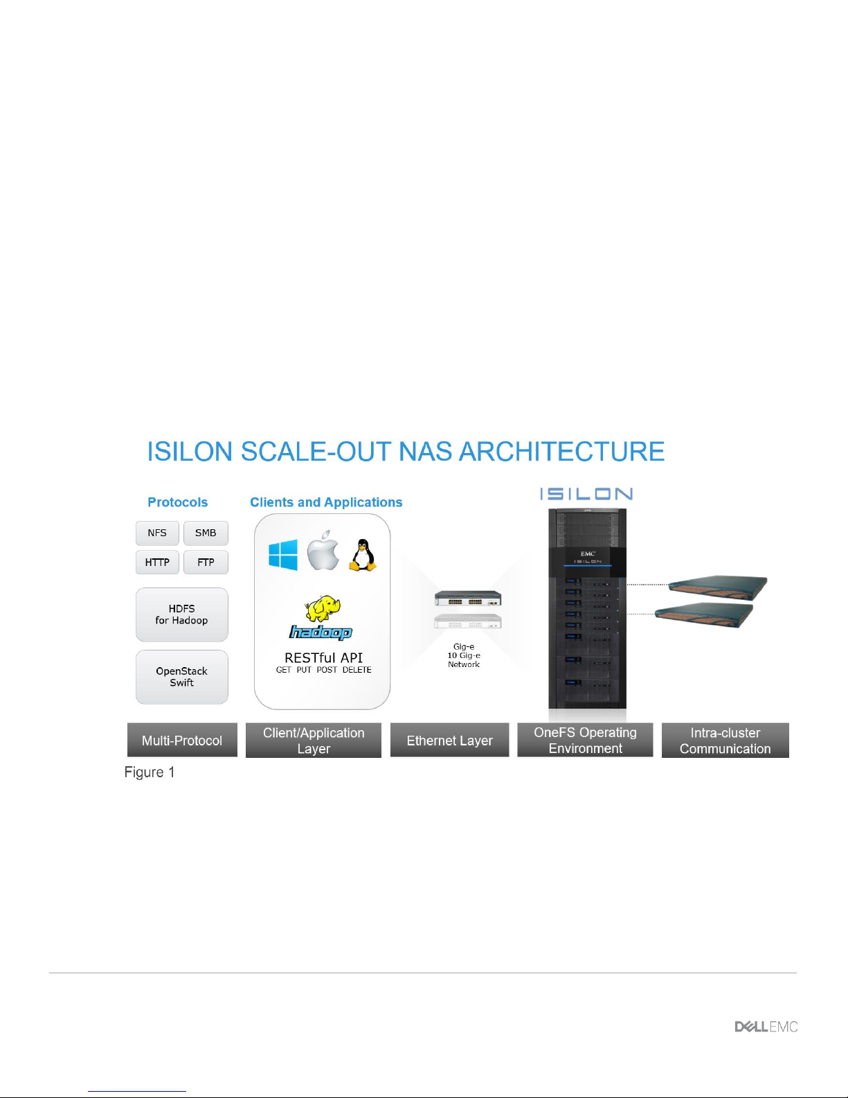
Isilon Scale-Out NAS
The Isilon Scale-out NAS utilizes Dell EMC Networking ethernet switches to provide the network. Dell EMC
Networking OS9 and the new OS10 Enterprise Edition (OS10EE) are used in the provided examples.
OS10EE is a disaggregated native Linux-based network operating system that has a fully disaggregated
software architecture. OS10EE decouples the base software from the Layer 2 and Layer 3 protocol stack and
services, which brings forth the ability for open programmability and portability. This allows for greater
utilization of Dell EMC’s Open Networking, in this guide we will utilize Dell EMC Networking operating
systems.

6 Dell EMC Networking with Isilon Front-End Deployment and Best Practices Guide | version 1.0
However, Dell EMC Networking's legacy OS9 is still prevalent in the industry and supported on a large crosssection of the currently-shipping portfolio. This document encompasses the use of both operating systems
within the same network architecture.
The Dell EMC S4048-ON will be used as leaf switches, and the Dell EMC Z9100-ON will be used in this guide
as a spine switch. The Dell EMC S3048-ON will be used as a management switch for the iDRAC
connections, out-of-band switch management, as well as the external Isilon connections. Z9100-ON and
S4048-ON leaf pair in rack 1 will utilize Dell EMC Networking OS10EE whereas the S3048-ON and S4048ON leaf pair in rack 2 will utilize OS9.
This guide will demonstrate how to utilize Dell EMC Networking, Dell EMC PowerEdge R730xd servers, and
the flexibility of Dell EMC Isilon OneFS in two separate topologies. The examples provided will be using the
Isilon X210. However, all Isilon storage systems utilize OneFS. This allows the steps outlined in this guide to
be used regardless of the hardware that is available.
The first example will highlight the benefits of using the dynamic routing protocol Border Gateway Protocol
(BGP) in a leaf/spine environment. This will be followed up with an example that displays the configuration
and benefits of a layer 2 leaf/spine topology.
While the steps in this document were validated using the specified Dell EMC Networking switches and
operating system(s), they may be leveraged for other Dell EMC Networking switch models utilizing the same
networking OS version or later assuming the switch has the available port numbers, speeds, and types.
Note: For more specific details on deploying a spine-leaf architecture using Dell EMC Networking see Dell
EMC Leaf-Spine Deployment Guide and Dell EMC Networking L3 Design for Leaf-Spine with OS10EE for
more information.
In addition to covering the details of the network configuration, specific configurations within OneFS will be
discussed. The focus will be on the front-end networking configurations, the back-end network that Isilon
utilizes is beyond the scope of this guide. The main configurations discussed within Isilon's OneFS will be as
follows:
• Creation of an Isilon cluster
• Adding additional nodes into the cluster
• Creating an SMB share
• Setting up LACP for each node in the cluster
• The configuration of the SmartConnect feature

7 Dell EMC Networking with Isilon Front-End Deployment and Best Practices Guide | version 1.0
1.1 Typographical conventions
The CLI and GUI examples in this document use the following conventions:
Monospace Text CLI examples
Underlined Monospace Text CLI examples that wrap the page. This text is entered as a single
command.
Italic Monospace Text Variables in CLI examples
Bold Monospace Text Commands entered at the CLI prompt
Bold text GUI fields and information entered in the GUI
1.2 Attachments
This .pdf includes switch configuration file attachments. To access attachments in Adobe Acrobat Reader,
click the icon in the left pane halfway down the page, then click the icon.
8 Dell EMC Networking with Isilon Front-End Deployment and Best Practices Guide | version 1.0
2 Hardware overview
This section briefly describes the hardware used to validate the deployment example in this guide. Appendix
A contains a complete listing of hardware and components.
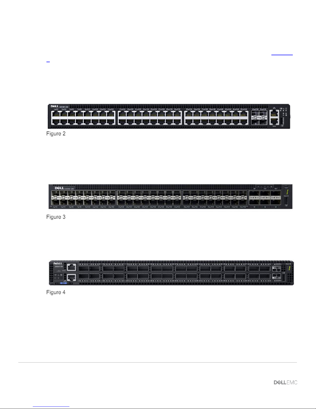
2.1 Dell EMC Networking S3048-ON
The Dell EMC Networking S3048-ON is a 1-Rack Unit (RU) switch with forty-eight 1GbE Base-T ports and
four 10GbE SFP+ ports. In this guide, one S3048-ON supports management traffic in each rack.
Dell EMC Networking S3048-ON
2.2 Dell EMC Networking S4048-ON
The S4048-ON is a 1RU switch with forty-eight 10GbE SFP+ ports and six ports of 40GbE. In this guide, this
switch is deployed as a leaf switch performing basic gateway functionality for attached Windows servers and
Isilon nodes.
Dell EMC Networking S4048-ON
2.3 Dell EMC Networking Z9100-ON
The Dell EMC Networking Z9100-ON is a 1RU, multilayer switch with thirty-two ports supporting
10/25/40/50/100GbE as well as two 10GbE ports. The Z9100-ON is used as a spine in this guide.
Dell EMC Networking Z9100-ON
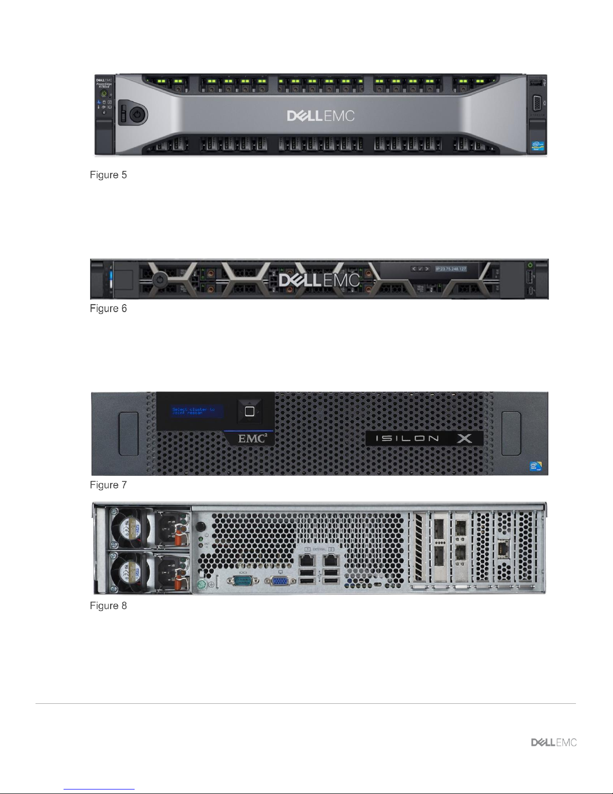
2.4 Dell EMC PowerEdge R730xd
The Dell EMC PowerEdge R730xd is a 2-RU, two-socket server platform. It allows up to 32 x 2.5” SSDs or
HDDs with SAS, SATA, and NVMe support. In this guide, two R730xd servers are used to connect to the
Isilon storage.
9 Dell EMC Networking with Isilon Front-End Deployment and Best Practices Guide | version 1.0
Dell EMC PowerEdge R730xd
2.5 Dell EMC PowerEdge R640
This R640 server is a 2-socket, 1 RU server. This server is used in the second rack to connect to the Isilon
storage.
Dell EMC PowerEdge R640
2.6 Isilon X210
The Dell EMC Isilon X210 is a 2-RU, scale-out NAS system. The Isilon X210 is used to create a storage
cluster to support an SMB share in this guide.
Dell EMC Isilon X210 front view
Dell EMC Isilon X210 rear view
10 Dell EMC Networking with Isilon Front-End Deployment and Best Practices Guide | version 1.0
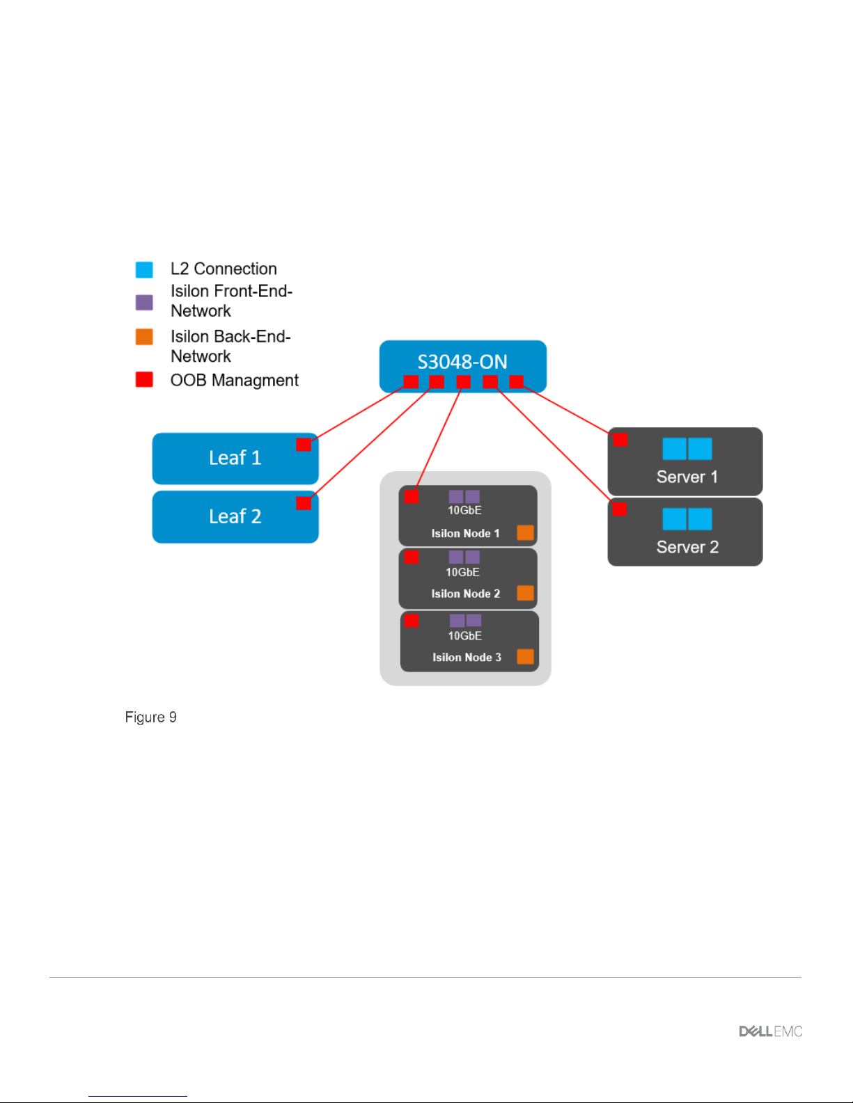
3 Management
The S3048-ON is used as a Top of Rack (ToR) switch, that aggregates all of the management connections.
Each switch has a connection from the out-of-band (OOB) management port to the ToR, as well as each
Isilon Node and PowerEdge server. The first Isilon node management connections are shown, each
additional node is cabled similarly. This can be seen in Figure 9 below, all equipment in other racks is
configured in a similar fashion.
Management configurations for rack 1
11 Dell EMC Networking with Isilon Front-End Deployment and Best Practices Guide | version 1.0
4 Leaf-spine overview
The connections between leaf and spine switches can be layer 2 (switched) or layer 3 (routed). The terms
“layer 3 topology” and “layer 2 topology” in this guide refer to these connections. In both topologies,
downstream connections to servers, storage and other endpoint devices within the racks are layer 2 and
connections to external networks are layer 3.
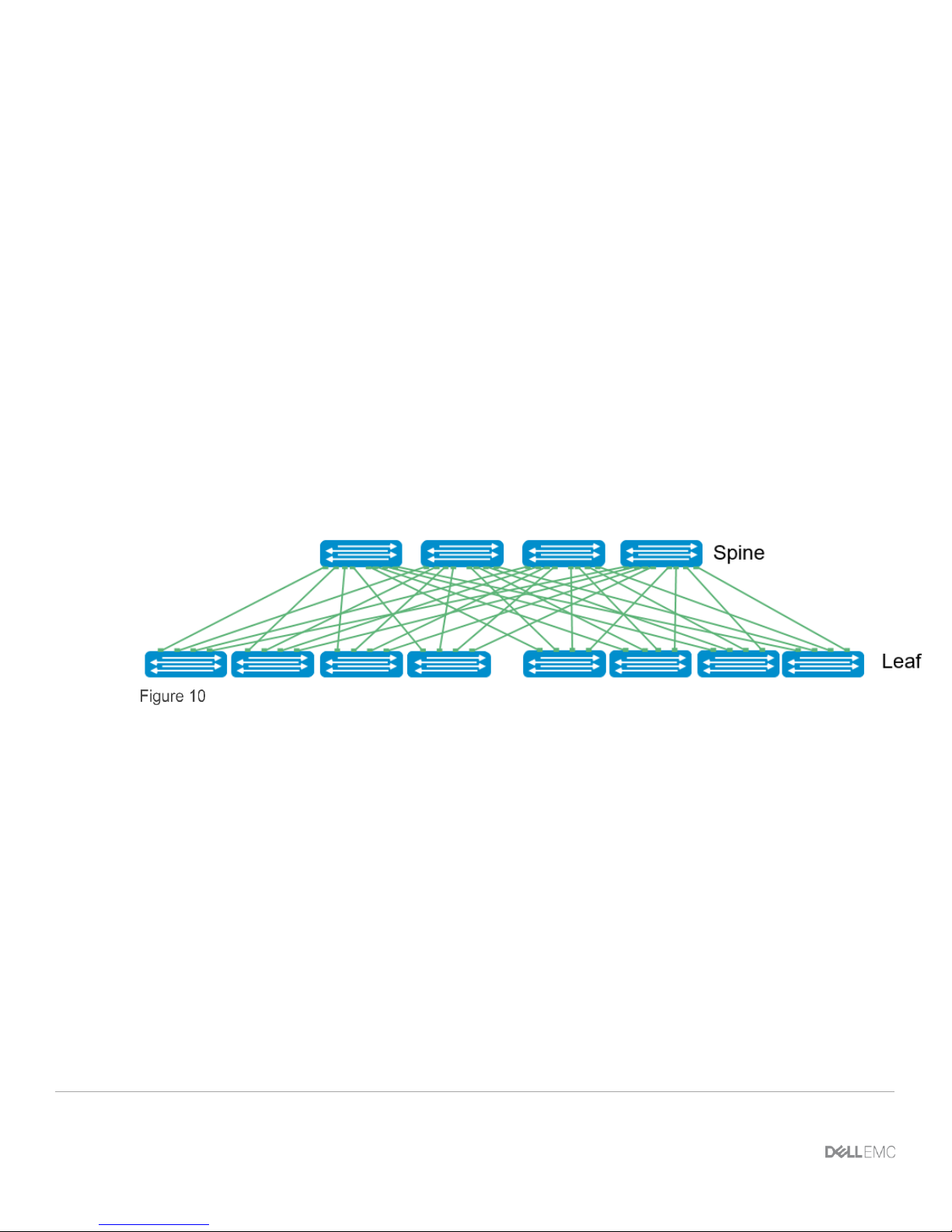
The following concepts apply to layer 2 and layer 3 leaf-spine topologies:
• Each leaf switch connects to every spine switch in the topology.
• Servers, storage arrays, edge routers and similar devices always connect to leaf switches, never to
spines.
The layer 2 and layer 3 topologies each use two leaf switches at the top of each rack configured as a Virtual
Link Trunking (VLT) pair. VLT allows all connections to be active while also providing fault tolerance. As
administrators add racks to the data center, two leaf switches configured for VLT are added to each new rack.
The total number of leaf-spine connections is equal to the number of leaf switches multiplied by the number of
spine switches. The bandwidth of the fabric may be increased by adding connections between the leaf and
spine layer as long as the spine layer has the capacity for the additional connections.
Leaf-Spine architecture
4.1 Design considerations
There are many different options regarding the selection of the correct topology that will best fit the needs of
the data center. In this section, the different protocols, topologies, and best practices will be covered. The
main differentiation will be whether the L2/L3 boundary is located at the spine layer or at the leaf layer. When
compared to a layer 3 topology, a layer 2 topology is generally less complex but has some limitations that
must be considered. These include:
• For each VLAN, the layer 2 topology creates one large broadcast domain across the fabric. The layer
3 topology has the benefit of containing broadcast domains to each rack.
• The layer 2 topology is limited to 4094 VLANs across the fabric. The layer 3 topology allows up to
4094 VLANs per rack.
• The layer 2 topology is limited to two physical switches at the spine layer (configured as VLT peers).
In a layer 3 topology, additional spines may be added as needed to provide additional paths and
bandwidth. Therefore, a layer 3 topology is more scalable and is better suited for very large networks.

12 Dell EMC Networking with Isilon Front-End Deployment and Best Practices Guide | version 1.0
• If none of the layer 2 limitations are a concern, it may ultimately come down to a matter of preference.
This guide provides examples of both topologies.
In addition to the considerations for the L2 topology, some options need to be considered in the L3 topology.
The primary design choice will be in the dynamic routing protocol that best fits the environment. BGP may be
selected for scalability and is well suited for very large networks, while OSPF is an interior gateway protocol
that provides routing inside an autonomous network. OSPF routers send link-state advertisements to all other
routers within the same autonomous system areas. This generally causes more memory and CPU usage than
BGP. However, OSPF may offer faster convergence. OSPF is often used in smaller networks.
Design choices that are common in both topologies include:
• Whether to use LACP or non-LACP configurations downstream.
• Configuring each leaf pair in a Virtual Link Trunking (VLT).
• Dell EMC recommends that RSTP always is configured as a best practice. Although configuring VLT
will create a loop free topology, RSTP will prevent loops if there is a misconfiguration in the network.
4.2 Oversubscription
Oversubscription is equal to the total amount of bandwidth available to all servers connected to a leaf switch
divided by the amount of uplink bandwidth. In a leaf-spine network, oversubscription occurs at the leaf layer.
Oversubscription = total bandwidth / uplink bandwidth
Other configurations are using available servers, storage and leaf switches that also could be used to manage
the subscription rates. The following are examples of oversubscription ratios based on downlink/uplink
bandwidth.
Oversubscription ratios based on uplink/downlink availability
NIC
Speed
#
Servers/Storage
interfaces/Leaf
Total Host
Bandwidth/Leaf
#
Spines
Spine Uplink
Speed
Total
Uplink
Bandwidth
Downlink/Uplink
Bandwidth
Oversubscription
Ratio
10GbE
19
190GbE
2
40GbE
80GbE
190/80
2.375 : 1
10GbE
19
190GbE
3
40GbE
120GbE
190/120
1.583 : 1
10GbE
19
190GbE
4
40GbE
160GbE
190/160
1.187 : 1
10GbE
38
380GbE
2
40GbE
80GbE
380/80
4.750 : 1
10GbE
38
380GbE
3
40GbE
120GbE
380/120
3.167 : 1
10GbE
38
380GbE
4
40GbE
160GbE
380/160
2.375 : 1
13 Dell EMC Networking with Isilon Front-End Deployment and Best Practices Guide | version 1.0
10GbE
38
380GbE
2
100GbE
80GbE
380/200
1.900 : 1
10GbE
38
380GbE
3
100GbE
120GbE
380/300
1.267 : 1
10GbE
38
380GbE
4
100GbE
160GbE
380/400
0.950 : 1
4.3 Scaling
An example of scaling this solution in a two-tier leaf-spine is a configuration of up to 16 racks. The Dell/EMC
Z9100-ON has thirty-two 40/100GbE interfaces that would support 16 leaf pairs using VLT. This provides one
rack that contains WAN-edge connectivity and 15 racks for servers and storage nodes. Each rack of the
compute/storage rack holding a combination of up to 19 PowerEdge R730’s or Isilon X210’s.
This particular example, each R730 has four 10GbE uplinks, and each Isilon node has four 10GbE uplinks
with 19 servers/nodes per rack. Additionally, the example architecture has four spine switches to minimize
oversubscription.
Connections for 16 racks with 4 spine switches
Server/Storage
interfaces
Server
connections to
leaf switches
Leaf connections to spine
switches per rack
Total connections for leaf
switches to four spine
switches
Connections
4
19 x 4 = 76
4 per leaf switch, 2 leaf
switches per rack = 8 links
16 racks * 8 = 128
Speed of
Ports
10 GbE
10 GbE
40 GbE
40 GbE
Total
theoretical
available
bandwidth
4 x 10 =
40GbE
76 x10 =
760GbE
8 * 40GbE per rack =
320GbE
16 * 320GbE = 5120GbE
This example provides for an oversubscription rate of 2.375:1 using 40GbE spine connectivity.
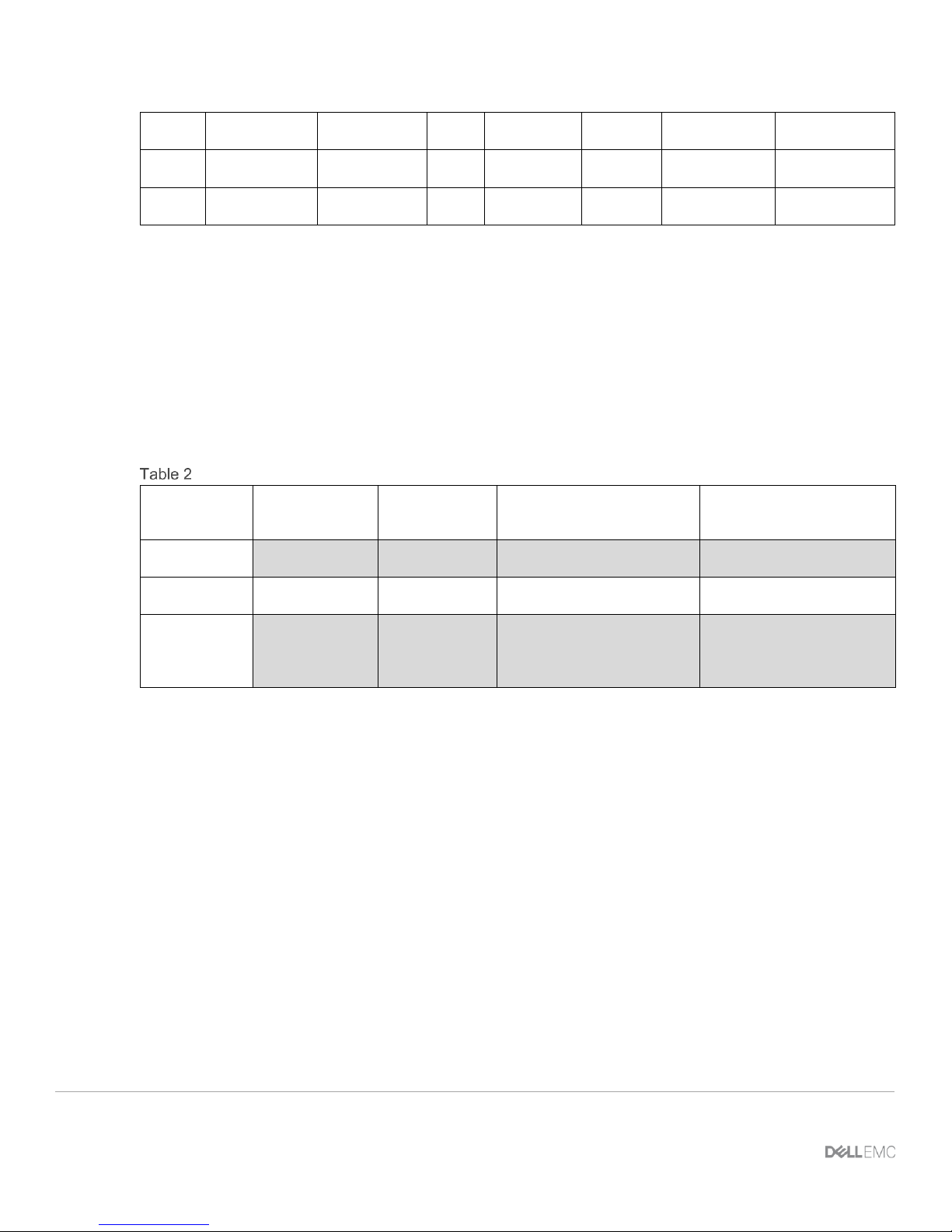
Scaling beyond 16 racks would require a three-tier leaf-spine network. The proof-of-concept scaling that
Figure 11 shows allows four 16-rack pods connected using an additional spine layer to scale in excess of
1,000 nodes with the same oversubscription ratio. This scenario requires reducing the number of racks
available per pod to accommodate the uplinks required to connect to the super spine layer.
It is important to understand the port-density of switches used and their feature sets’ impact on the number of
available ports. This directly influences the number of switches necessary for proper scaling.
14 Dell EMC Networking with Isilon Front-End Deployment and Best Practices Guide | version 1.0
Scaling out the existing networking topology
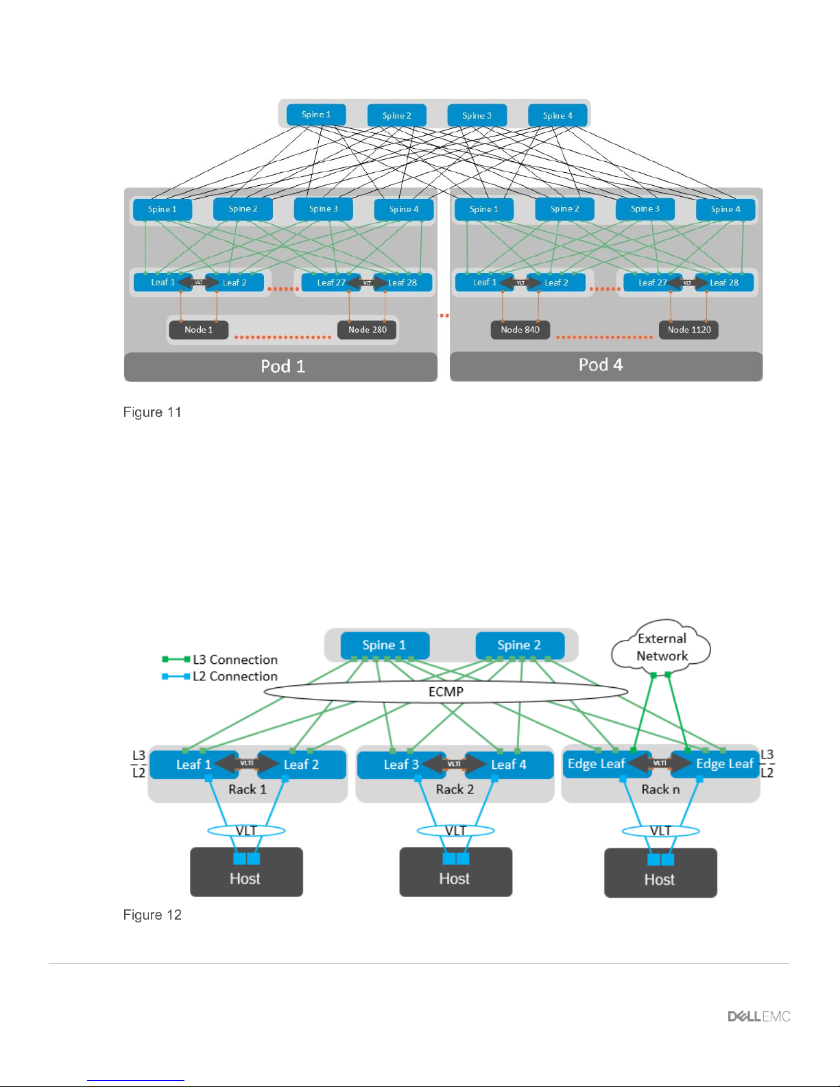
4.4 Layer 3 leaf-spine topology
In a layer 3 leaf-spine network, traffic between leafs and spines is routed. The layer 2/3 boundary is at the leaf
switches. Spine switches are never connected to each other in a layer 3 topology. Equal cost multi-path
routing (ECMP) is used to load balance traffic across the layer 3 network. Connections within racks from
hosts to leaf switches are layer 2. Connections to external networks are made from a pair of edge or border
leafs as shown in Figure 12.
Layer 3 leaf-spine network
15 Dell EMC Networking with Isilon Front-End Deployment and Best Practices Guide | version 1.0
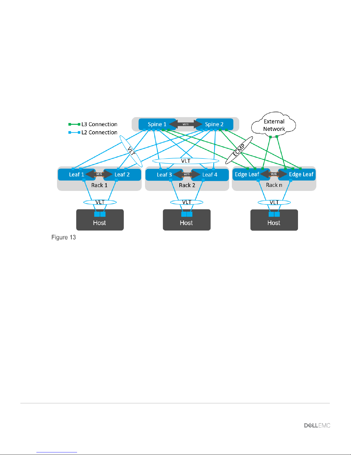
4.5 Layer 2 leaf-spine topology
In a layer 2 leaf-spine network, traffic between leafs and spines is switched (except for a pair of edge leafs) as
shown in Figure 13. VLT is used for multipathing and load balancing traffic across the layer 2 leaf-spine fabric.
Connections from hosts to leaf switches are also layer 2.
For connections to external networks, layer 3 links are added between the spines and a pair of edge leafs.
Layer 2 leaf-spine network
16 Dell EMC Networking with Isilon Front-End Deployment and Best Practices Guide | version 1.0
5 Layer 3 Topology preparation
The layer 3 topology used in this example will use external border gateway protocol (eBGP) as well as ECMP.
In order to correctly configure this topology, several things need to be considered and planned.
5.1 BGP ASN configuration
When eBGP is used, an autonomous system number (ASN) is assigned to each switch. Valid private, 2-byte
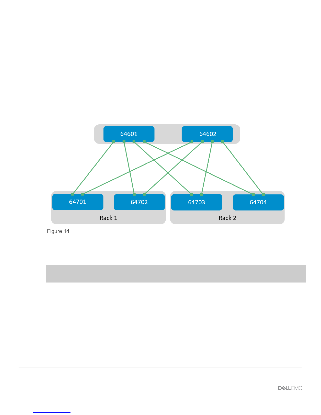
ASNs range from 64512 through 65534. Figure 14 shows the ASN assignments used for leaf and spine
switches in the BGP examples in this guide.
BGP ASN assignments
ASNs should follow a logical pattern for ease of administration and allow for growth as additional leaf and
spine switches are added. In this example, an ASN with a “6” in the hundreds place represents a spine switch
(e.g., 64601), and an ASN with a “7” in the hundreds place represents a leaf switch (e.g., 64701).
Note: The same ASN can be used across all tier-2 spine switches if the growth plans do not require an
additional layer of spine switches.
5.2 Loopback addresses
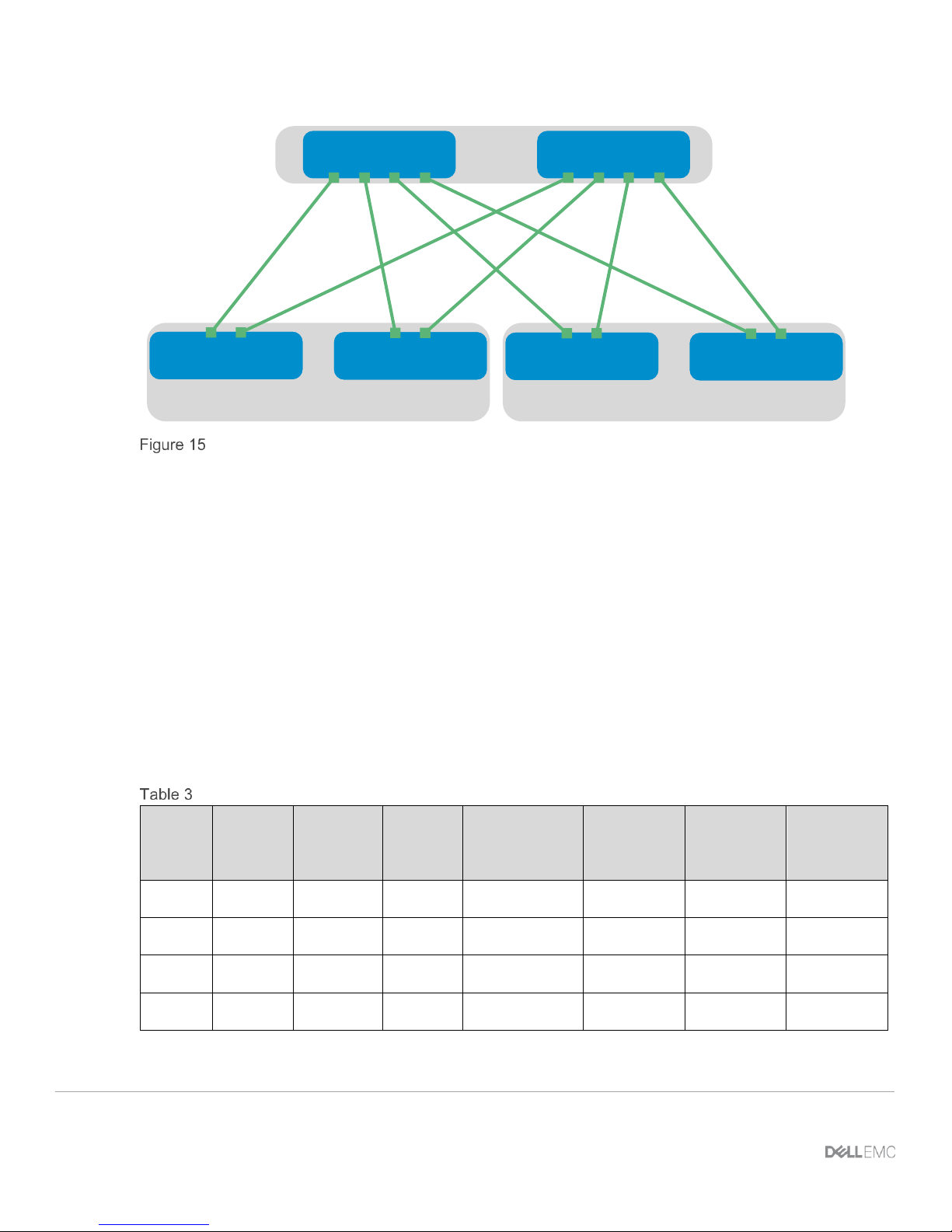
Loopback addresses may be used as router IDs when configuring routing protocols. As with ASNs, loopback
addresses should follow a logical pattern that will make it easier for administrators to manage the network and
allow for growth. Figure 15 shows the loopback addresses used as router IDs in the example provided.
17 Dell EMC Networking with Isilon Front-End Deployment and Best Practices Guide | version 1.0
Rack 2Rack 1
10.0.1.1/32 10.0.1.2/32
10.0.2.1/32
10.0.2.2/32
10.0.2.3/32
10.0.2.4/32
Loopback addressing
All loopback addresses used are part of the 10.0.0.0/8 address space with each address using a 32-bit mask.
In this example, the third octet represents the layer, “1” for the spine and “2” for the leaf. The fourth octet is
the counter for the appropriate layer. For example, 10.0.1.1/32 is the first spine switch in the topology while
10.0.2.4/32 is the fourth leaf switch.
5.3 Point-to-point interfaces
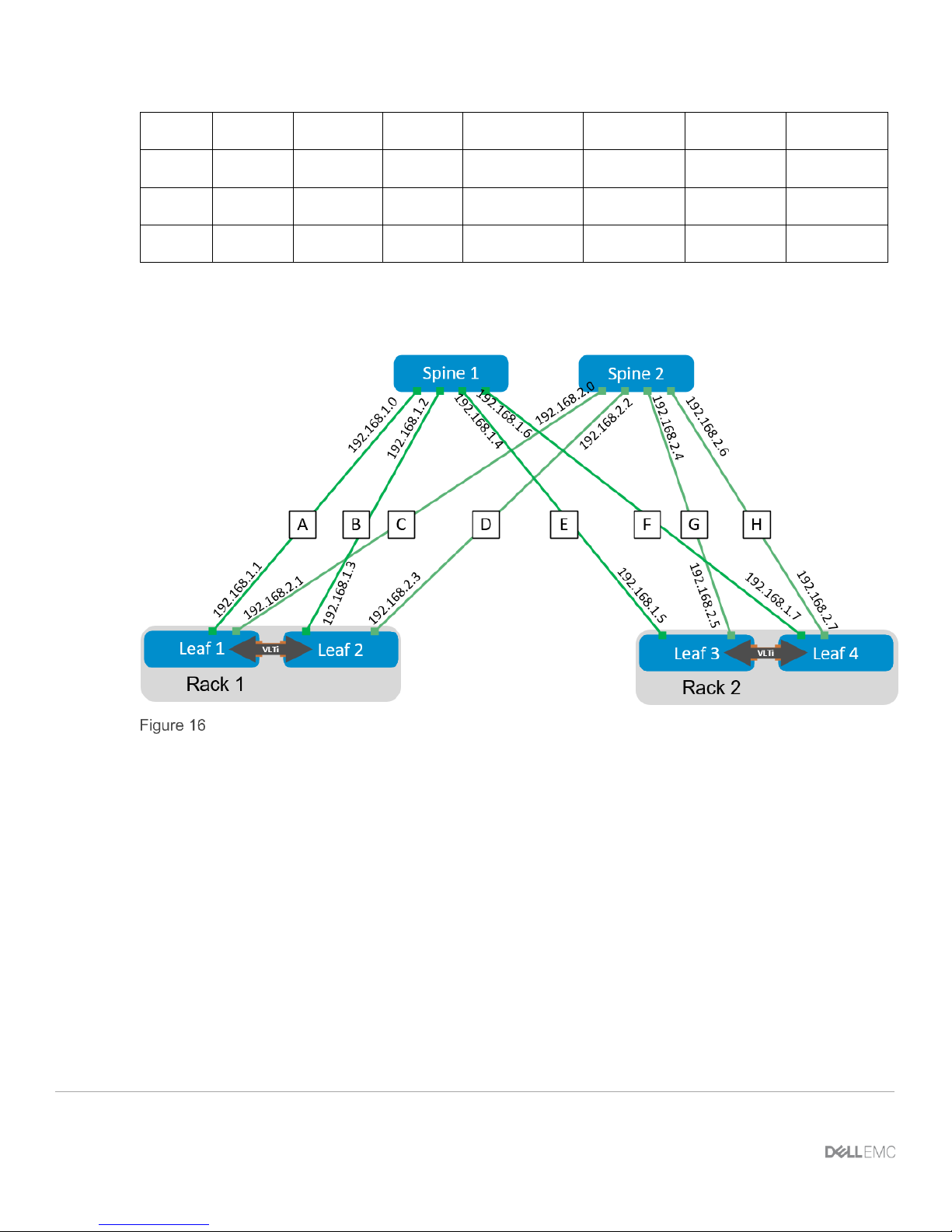
Table 3 lists layer 3 connection details for each leaf and spine switch.
All addresses come from the same base IP prefix, 192.168.0.0/16 with the third octet representing the spine
number. For example, 192.168.1.0/31 is a two-host subnet connected to Spine 1 while 192.168.2.0/31 is
connected to Spine 2. This IP scheme is easily extended as leaf and spine switches are added to the
network.
Link labels are provided in the table for quick reference with Figure 16.
Interface and IP configuration
Link
Label
Source
switch
Source
interface
Source
IP
Network
Destination
switch
Destination
interface
Destination
IP
A
Leaf 1
Eth1/1/49
.1
192.168.1.0/31
Spine 1
Eth1/1/1
.0
B
Leaf 1
Eth1/1/50
.1
192.168.2.0/31
Spine 2
Eth1/1/1
.0
C
Leaf 2
Eth1/1/49
.3
192.168.1.2/31
Spine 1
Eth1/1/2
.2 D Leaf 2
Eth1/1/50
.3
192.168.2.2/31
Spine 2
Eth1/1/2
.2
18 Dell EMC Networking with Isilon Front-End Deployment and Best Practices Guide | version 1.0
E
Leaf 3
Eth1/1/49
.5
192.168.1.4/31
Spine 1
Eth1/1/3
.4 F Leaf 3
Eth1/1/50
.5
192.168.2.4/31
Spine 2
Eth1/1/3
.4
G
Leaf 4
Eth1/1/49
.7
192.168.1.6/31
Spine 1
Eth1/1/4
.6
H
Leaf 4
Eth1/1/50
.7
192.168.2.6/31
Spine 2
Eth1/1/4
.6
The point-to-point IP addresses used in this guide are shown in Figure 16:
Point-to-point IP addresses
19 Dell EMC Networking with Isilon Front-End Deployment and Best Practices Guide | version 1.0
6 Configuration of Layer 3 Topology
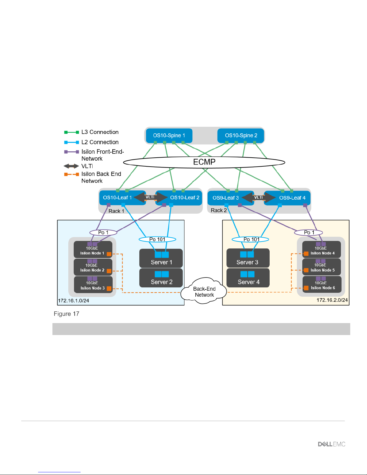
This section will cover the configuration of the layer 3 topology. In the example provided there are three Isilon
nodes connected to each leaf pair as well as two Dell PowerEdge servers that will be consuming the storage.
The connections for the first node are shown in the diagram. Each subsequent node is cabled similarly. The
configurations for all connections are detailed in the following sections. The Isilon nodes will all connect on the
back-end network through two InfiniBand switches, creating one single six node cluster. The Isilon back-end
networking is not covered in this guide.
Layer 3 Topology
Note: The configuration files for every switch in this topology are listed in the attachments section.
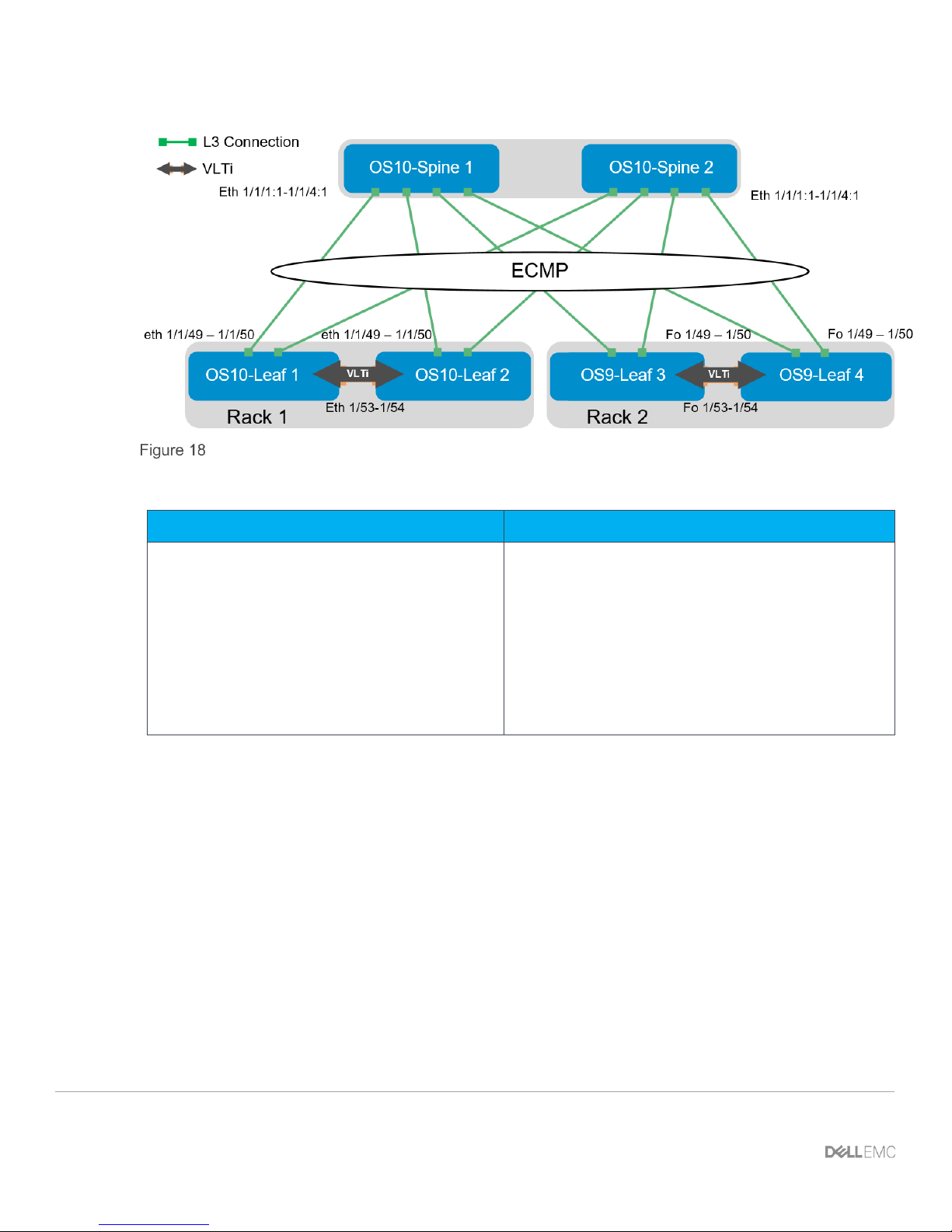
6.1 Configuration of Z9100-ON OS10EE Spine Switches
The configuration of the example used in this guide will begin with the two Z9100-ON’s Spine1 and Spine2 as
seen in Figure 18.
20 Dell EMC Networking with Isilon Front-End Deployment and Best Practices Guide | version 1.0
OS10EE Spine
Set the hostname, configure the OOB management interface and default gateway.
Z9100-ON Spine 1
Z9100-ON Spine 2
configure terminal
hostname Z9100-Spine1
interface mgmt 1/1/1
no ip address dhcp
no shutdown
ip address 100.67.169.37/24
management route 0.0.0.0/0 100.67.169.254
configure terminal
hostname Z9100-Spine2
interface mgmt 1/1/1
no ip address dhcp
no shutdown
ip address 100.67.169.36/24
management route 0.0.0.0/0 100.67.169.254
Configure the four point-to-point interfaces connected to leaf switches. In this example, each of the
connections from the Z9100-ON spine to the S4048-ON leaf switches needs to have the speed set to 40GbE.
Next, assign IP addresses per Table 3. Configure a loopback interface to be used as the router ID. Isilon’s
OneFS supports and recommends the use of jumbo frames. Each interface used below will be configured
using jumbo frames.

21 Dell EMC Networking with Isilon Front-End Deployment and Best Practices Guide | version 1.0
Z9100-ON Spine 1
Z9100-ON Spine 2
interface breakout 1/1/1 map 40g-1x
interface breakout 1/1/2 map 40g-1x
interface breakout 1/1/3 map 40g-1x
interface breakout 1/1/4 map 40g-1x
interface ethernet1/1/1:1
description “S4048-Leaf1”
no shutdown
no switchport
mtu 9216
ip address 192.168.1.0/31
interface ethernet1/1/2:1
description “S4048-Leaf2”
no shutdown
no switchport
mtu 9216
ip address 192.168.1.2/31
interface ethernet1/1/3:1
description “S4048-Leaf3”
no shutdown
no switchport
mtu 9216
ip address 192.168.1.4/31
interface ethernet1/1/4:1
description “S4048-Leaf4”
no shutdown
no switchport
mtu 9216
ip address 192.168.1.6/31
interface loopback0
description “Router ID”
no shutdown
ip address 10.0.1.1/32
interface breakout 1/1/1 map 40g-1x
interface breakout 1/1/2 map 40g-1x
interface breakout 1/1/3 map 40g-1x
interface breakout 1/1/4 map 40g-1x
interface ethernet1/1/1:1
description “S4048-Leaf1”
no shutdown
no switchport
mtu 9216
ip address 192.168.2.0/31
interface ethernet1/1/2:1
description “S4048-Leaf2”
no shutdown
no switchport
mtu 9216
ip address 192.168.2.2/31
interface ethernet1/1/3:1
description “S4048-Leaf3”
no shutdown
no switchport
mtu 9216
ip address 192.168.2.4/31
interface ethernet1/1/4:1
description “S4048-Leaf4”
no shutdown
no switchport
mtu 9216
ip address 192.168.2.6/31
interface loopback0
description “Router ID”
no shutdown
ip address 10.0.1.2/32
Configure a route map and IP prefix list to redistribute all loopback addresses and leaf networks via BGP.
The command seq 10 permit 10.0.1.0/24 ge 32 includes all addresses in the 10.0.1.0/24 address
range with a mask greater than or equal to 32. This includes all loopback addresses used as router IDs.

22 Dell EMC Networking with Isilon Front-End Deployment and Best Practices Guide | version 1.0
Z9100-ON Spine 1
Z9100-ON Spine 2
route-map spine-leaf permit 10
match ip address prefix-list spine-leaf
ip prefix-list spine-leaf seq 10 permit 10.0.1.0/24 ge
32
route-map spine-leaf permit 10
match ip address prefix-list spine-leaf
ip prefix-list spine-leaf seq 10 permit 10.0.1.0/24 ge
32
Use these commands to configure BGP.
First, enable eBGP with the router bgp ASN command. The ASN is from Figure 14.
The bgp bestpath as-path multipath-relax command enables ECMP. The maximum-paths ebgp
2 command specifies the maximum number of parallel paths to a destination to add to the routing table. In
this topology, there are two equal cost best paths from a spine to a host, one to each leaf that the host is
connected.
BGP neighbors are configured, and Neighbor fall-over is enabled. Graceful restart enables the data plane to
continue forwarding traffic for a time if the BGP process fails or quits.
BGP hello and hold down timers are set to three and nine seconds, respectively. Neighbor fall-over will trigger
route withdrawal when IP connectivity between BGP peers is lost. The more aggressive timers (default is 60
seconds hello and 180 seconds hold down) are for backup. The advertisement interval is set to one second.
This is to prevent BGP speakers from advertising updates immediately upon receipt. Instead, they will
advertise them in batched intervals of one second. This delay is to prevent overhead.
Finally, exit configuration mode and save the configuration.

23 Dell EMC Networking with Isilon Front-End Deployment and Best Practices Guide | version 1.0
Z9100-ON Spine 1
Z9100-ON Spine 2
router bgp 64601
bestpath as-path multipath-relax
graceful-restart role receiver-only
maximum-paths ebgp 2
address-family ipv4 unicast
redistribute connected route-map spine-leaf
template spine-leaf
advertisement-interval 1
fall-over
timers 3 9
neighbor 192.168.1.1
inherit template spine-leaf
remote-as 64701
no shutdown
neighbor 192.168.1.3
inherit template spine-leaf
remote-as 64702
no shutdown
neighbor 192.168.1.5
inherit template spine-leaf
remote-as 64703
no shutdown
neighbor 192.168.1.7
inherit template spine-leaf
remote-as 64704
no shutdown
end
write memory
router bgp 64602
bestpath as-path multipath-relax
graceful-restart role receiver-only
maximum-paths ebgp 2
address-family ipv4 unicast
redistribute connected route-map spine-leaf
template spine-leaf
advertisement-interval 1
fall-over
timers 3 9
neighbor 192.168.2.1
inherit template spine-leaf
remote-as 64701
no shutdown
neighbor 192.168.2.3
inherit template spine-leaf
remote-as 64702
no shutdown
neighbor 192.168.2.5
inherit template spine-leaf
remote-as 64703
no shutdown
neighbor 192.168.2.7
inherit template spine-leaf
remote-as 64704
no shutdown
end
write memory
6.2 Configuration of S4048-ON OS10EE Leaf Switches
Configurations of the leaf switches one and two running OS10EE will be shown next as seen in Figure 19.
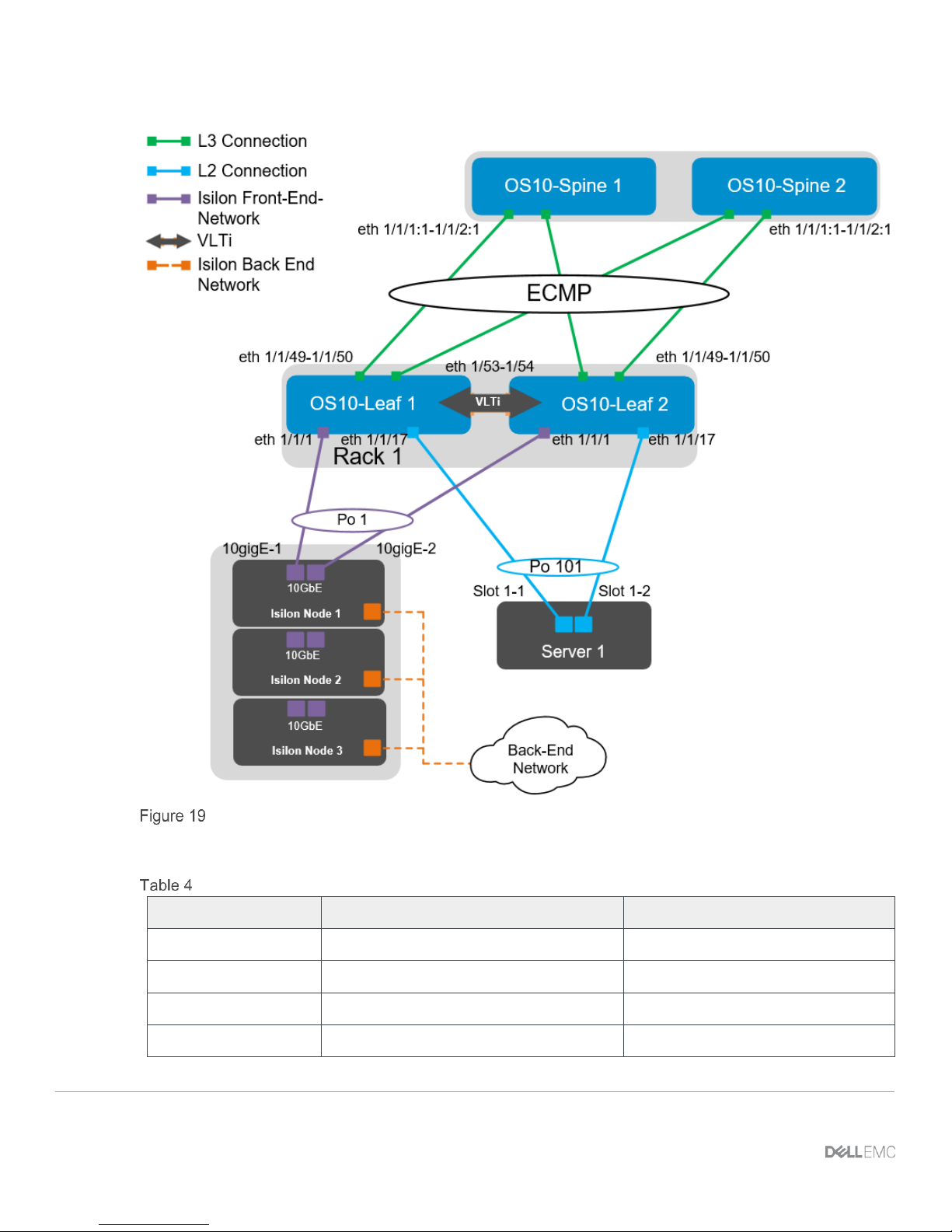
24 Dell EMC Networking with Isilon Front-End Deployment and Best Practices Guide | version 1.0
OS10EE Leaf pair
The interfaces for additional Isilon nodes and servers in this example can be found in the following table:
Interface enumeration
Server/Isilon Node
Switch
Leaf interface
Node 01-1
Leaf 1
ethernet 1/1/1
Leaf 2
ethernet 1/1/1
Node 01-2
Leaf 1
ethernet 1/1/3
Leaf 2
ethernet 1/1/3
 Loading...