


Dell inspiron 7500 schematic

Dell™ Inspiron™ 7500
REMOVING AND
REPLACING PARTS
www.dell.com
support.dell.com
™

Notes, Notices, and Cautions
Throughout this guide, blocks of text may be accompanied by an icon and printed in
bold type or in italic type. These blocks are notes, notices, cautions, and warnings,
and they are used as follows:
NOTE: A NOTE indicates important information that helps you make better use of
your computer system.
NOTICE: A NOTICE indicates either potential damage to hardware or loss
of data and tells you how to avoid the problem.
CAUTION: A CAUTION indicates a potentially hazardous situation which, if
not avoided, may result in minor or moderate injury.
___________________ _
Information in this document is subject to change without notice.
© 2000 Dell Computer Corporation. All rights reserved.
Reproduction in any manner whatsoever without the written permission of Dell Computer Corporation is strictly forbidden.
Trademarks used in this text: Dell, the DELL logo, Inspiron,
Other trademarks and trade names may be used in this document to refer to either the entities
claiming the marks and names or their products. Dell Computer Corporation disclaims any proprietary interest in trademarks and trade names other than its own.
March 2000 P/N 679DC Rev. A00

Contents
Precautionary Measures . . . . . . . . . . . . . . . . . . . . . . . . . . . . . . . . . . . . . . . . . . . . . . .1
Recommended Tools . . . . . . . . . . . . . . . . . . . . . . . . . . . . . . . . . . . . . . . . . . . . . . . . . 9
Screw Identification and Tightening . . . . . . . . . . . . . . . . . . . . . . . . . . . . . . . . . . . . .10
Exploded View of Computer . . . . . . . . . . . . . . . . . . . . . . . . . . . . . . . . . . . . . . . . . . .12
Exploded View of 15-Inch XGA Display Assembly . . . . . . . . . . . . . . . . . . . . . . . . . . 13
Exploded View of 15-Inch SXGA+ Display Assembly . . . . . . . . . . . . . . . . . . . . . . . . 14
Exploded View of 15.4-Inch SXGA Display Assembly . . . . . . . . . . . . . . . . . . . . . . . .15
Hard-Disk Drive Disassembly . . . . . . . . . . . . . . . . . . . . . . . . . . . . . . . . . . . . . . . . . .16
Combo Module Disassembly . . . . . . . . . . . . . . . . . . . . . . . . . . . . . . . . . . . . . . . . . .17
Keyboard Removal. . . . . . . . . . . . . . . . . . . . . . . . . . . . . . . . . . . . . . . . . . . . . . . . . . . 21
ZIF Connectors . . . . . . . . . . . . . . . . . . . . . . . . . . . . . . . . . . . . . . . . . . . . . . . . . . . . .22
Thermal Shield and Internal Modem Removal . . . . . . . . . . . . . . . . . . . . . . . . . . . . .23
Heat Exchanger/Fan Removal . . . . . . . . . . . . . . . . . . . . . . . . . . . . . . . . . . . . . . . . . .26
Processor Board Removal . . . . . . . . . . . . . . . . . . . . . . . . . . . . . . . . . . . . . . . . . . . . . 27
LCD Removal. . . . . . . . . . . . . . . . . . . . . . . . . . . . . . . . . . . . . . . . . . . . . . . . . . . . . . . 28
Palmrest Component Assembly . . . . . . . . . . . . . . . . . . . . . . . . . . . . . . . . . . . . . . . . 30
Palmrest Assembly Removal . . . . . . . . . . . . . . . . . . . . . . . . . . . . . . . . . . . . . . .32
Palmrest Assembly Component Removal. . . . . . . . . . . . . . . . . . . . . . . . . . . . . . . . . 34
IR Board Removal. . . . . . . . . . . . . . . . . . . . . . . . . . . . . . . . . . . . . . . . . . . . . . . . 34
Touch Pad Assembly Removal . . . . . . . . . . . . . . . . . . . . . . . . . . . . . . . . . . . . . . 35
Hard-Disk Drive Heat Shield Removal . . . . . . . . . . . . . . . . . . . . . . . . . . . . . . . . 37
Speaker Removal . . . . . . . . . . . . . . . . . . . . . . . . . . . . . . . . . . . . . . . . . . . . . . . .38
PC Card Heat Sink Removal . . . . . . . . . . . . . . . . . . . . . . . . . . . . . . . . . . . . . . . . . . .39
DC-DC Board Removal . . . . . . . . . . . . . . . . . . . . . . . . . . . . . . . . . . . . . . . . . . . . . . .40
Hinge Saddle Removal . . . . . . . . . . . . . . . . . . . . . . . . . . . . . . . . . . . . . . . . . . . . . . .41
RJ-11 Card Removal . . . . . . . . . . . . . . . . . . . . . . . . . . . . . . . . . . . . . . . . . . . . . . . . . 42
System Board Removal. . . . . . . . . . . . . . . . . . . . . . . . . . . . . . . . . . . . . . . . . . . . . . .43
PC Card Cage Removal . . . . . . . . . . . . . . . . . . . . . . . . . . . . . . . . . . . . . . . . . . . . . . . 44
Audio Card and Audio Thermal Shield Removal . . . . . . . . . . . . . . . . . . . . . . . . . . . . 45
v

Latch Assembly Removal . . . . . . . . . . . . . . . . . . . . . . . . . . . . . . . . . . . . . . . . . . . . . 46
Display Assembly and Display Assembly Component Removal. . . . . . . . . . . . . . . . 47
Display Assembly Component Removal . . . . . . . . . . . . . . . . . . . . . . . . . . . . . . . . . . 48
15-Inch LCD Panel Removal . . . . . . . . . . . . . . . . . . . . . . . . . . . . . . . . . . . . . . . 49
Exploded View of Base Assembly . . . . . . . . . . . . . . . . . . . . . . . . . . . . . . . . . . . . . . 51
Figures Figure 1. AC Adapter . . . . . . . . . . . . . . . . . . . . . . . . . . . . . . . . . . . . . . . . . . . . . . 2
Figure 2. Port Replicator . . . . . . . . . . . . . . . . . . . . . . . . . . . . . . . . . . . . . . . . . . . . 3
Figure 3. Battery Compartment . . . . . . . . . . . . . . . . . . . . . . . . . . . . . . . . . . . . . . 4
Figure 4. PC Card Removal . . . . . . . . . . . . . . . . . . . . . . . . . . . . . . . . . . . . . . . . . . 5
Figure 5. Hard-Disk Drive Assembly Removal . . . . . . . . . . . . . . . . . . . . . . . . . . . 5
Figure 6. Memory Module Covers . . . . . . . . . . . . . . . . . . . . . . . . . . . . . . . . . . . . 6
Figure 7. Memory Modules . . . . . . . . . . . . . . . . . . . . . . . . . . . . . . . . . . . . . . . . . 7
Figure 8. Video Card Removal . . . . . . . . . . . . . . . . . . . . . . . . . . . . . . . . . . . . . . . 8
Figure 9. Media Bay Module Removal . . . . . . . . . . . . . . . . . . . . . . . . . . . . . . . . . 9
Figure 10. Computer Components . . . . . . . . . . . . . . . . . . . . . . . . . . . . . . . . . . . 12
Figure 11. 15-Inch XGA Display Components . . . . . . . . . . . . . . . . . . . . . . . . . . . 13
Figure 12. 15-Inch SXGA+ Display Components . . . . . . . . . . . . . . . . . . . . . . . . . 14
Figure 13. 15.4-Inch SXGA Display Components . . . . . . . . . . . . . . . . . . . . . . . . . 15
Figure 14. Hard-Disk Drive Components . . . . . . . . . . . . . . . . . . . . . . . . . . . . . . . 16
Figure 15. Combo Module Components . . . . . . . . . . . . . . . . . . . . . . . . . . . . . . . 18
Figure 16. Side Mounting Bracket Removal . . . . . . . . . . . . . . . . . . . . . . . . . . . . . 19
Figure 17. Keyboard Components . . . . . . . . . . . . . . . . . . . . . . . . . . . . . . . . . . . . 21
Figure 18. ZIF Connector Release . . . . . . . . . . . . . . . . . . . . . . . . . . . . . . . . . . . . 22
Figure 19. Thermal Shield/Internal Modem Components. . . . . . . . . . . . . . . . . . . 24
Figure 20. Heat Exchanger/Fan Components . . . . . . . . . . . . . . . . . . . . . . . . . . . . 26
Figure 21. Processor Board Components. . . . . . . . . . . . . . . . . . . . . . . . . . . . . . . 27
Figure 22. LCD Components . . . . . . . . . . . . . . . . . . . . . . . . . . . . . . . . . . . . . . . . 28
Figure 23. Exploded View of Palmrest Assembly . . . . . . . . . . . . . . . . . . . . . . . . . 30
Figure 24. Palmrest Assembly Components . . . . . . . . . . . . . . . . . . . . . . . . . . . . 32
Figure 25. IR Board Components . . . . . . . . . . . . . . . . . . . . . . . . . . . . . . . . . . . . . 34
Figure 26. Touch Pad . . . . . . . . . . . . . . . . . . . . . . . . . . . . . . . . . . . . . . . . . . . . . . 35
Figure 27. Touch Pad Assembly Components . . . . . . . . . . . . . . . . . . . . . . . . . . . 35
Figure 28. Hard-Disk Drive Heat Shield Components . . . . . . . . . . . . . . . . . . . . . 37
Figure 29. Speaker Components . . . . . . . . . . . . . . . . . . . . . . . . . . . . . . . . . . . . . 38
Figure 30. PC Card Heat Sink Components . . . . . . . . . . . . . . . . . . . . . . . . . . . . . 39
Figure 31. DC-DC Board . . . . . . . . . . . . . . . . . . . . . . . . . . . . . . . . . . . . . . . . . . . . 40
Figure 32. Hinge Saddle Components . . . . . . . . . . . . . . . . . . . . . . . . . . . . . . . . . 41
Figure 33. RJ-11 Card Components . . . . . . . . . . . . . . . . . . . . . . . . . . . . . . . . . . . 42
Figure 34. System Board Components . . . . . . . . . . . . . . . . . . . . . . . . . . . . . . . . 43
Figure 35. PC Card Cage Components . . . . . . . . . . . . . . . . . . . . . . . . . . . . . . . . 44
Figure 36. Audio Card/Thermal Shield Components . . . . . . . . . . . . . . . . . . . . . . 45
Figure 37. Latch Assembly Components . . . . . . . . . . . . . . . . . . . . . . . . . . . . . . . 46
vi

Figure 38. Display Assembly Removal . . . . . . . . . . . . . . . . . . . . . . . . . . . . . . . . . 47
Figure 39. Front Bezel Removal . . . . . . . . . . . . . . . . . . . . . . . . . . . . . . . . . . . . . .48
Figure 40. Base Assembly Components. . . . . . . . . . . . . . . . . . . . . . . . . . . . . . . .51
Tables Table 1. Screw Identification and Location . . . . . . . . . . . . . . . . . . . . . . . . . . . . 11
vii

viii

Table 1. Screw Identification and Location . . . . . . . . . . . . . . . . . . . . . . . . . . . . 11
ix

Figure 1.
Figure 2.
Figure 3.
Figure 4.
AC Adapter
Port Replicator
Battery Compartment
PC Card Removal . . . . . . . . . . . . . . . . . . . . . . . . . . . . . . . . . . . . . . . . . 5
. . . . . . . . . . . . . . . . . . . . . . . . . . . . . . . . . . . . . . . . . . . . . 2
. . . . . . . . . . . . . . . . . . . . . . . . . . . . . . . . . . . . . . . . . . . 3
. . . . . . . . . . . . . . . . . . . . . . . . . . . . . . . . . . . . . 4
Figure 5. Hard-Disk Drive Assembly Removal . . . . . . . . . . . . . . . . . . . . . . . . . . . 5
Figure 6. Memory Module Covers . . . . . . . . . . . . . . . . . . . . . . . . . . . . . . . . . . . . 6
Figure 7. Memory Modules . . . . . . . . . . . . . . . . . . . . . . . . . . . . . . . . . . . . . . . . . 7
Figure 8. Video Card Removal . . . . . . . . . . . . . . . . . . . . . . . . . . . . . . . . . . . . . . . 8
Figure 9. Media Bay Module Removal . . . . . . . . . . . . . . . . . . . . . . . . . . . . . . . . . 9
Figure 10. Computer Components . . . . . . . . . . . . . . . . . . . . . . . . . . . . . . . . . . . 12
Figure 11. 15-Inch XGA Display Components . . . . . . . . . . . . . . . . . . . . . . . . . . . 13
Figure 12. 15-Inch SXGA+ Display Components . . . . . . . . . . . . . . . . . . . . . . . . . 14
Figure 13. 15.4-Inch SXGA Display Components . . . . . . . . . . . . . . . . . . . . . . . . . 15
Figure 14. Hard-Disk Drive Components . . . . . . . . . . . . . . . . . . . . . . . . . . . . . . . 16
Figure 15. Combo Module Components . . . . . . . . . . . . . . . . . . . . . . . . . . . . . . . 18
Figure 16. Side Mounting Bracket Removal . . . . . . . . . . . . . . . . . . . . . . . . . . . . . 19
Figure 17. Keyboard Components . . . . . . . . . . . . . . . . . . . . . . . . . . . . . . . . . . . . 21
Figure 18. ZIF Connector Release . . . . . . . . . . . . . . . . . . . . . . . . . . . . . . . . . . . . 22
Figure 19.
Thermal Shield/Internal Modem Components
. . . . . . . . . . . . . . . . 24
Figure 20. Heat Exchanger/Fan Components . . . . . . . . . . . . . . . . . . . . . . . . . . . . 26
Figure 21. Processor Board Components. . . . . . . . . . . . . . . . . . . . . . . . . . . . . . . 27
Figure 22. LCD Components . . . . . . . . . . . . . . . . . . . . . . . . . . . . . . . . . . . . . . . . 28
Figure 23.
Exploded View of Palmrest Assembly
. . . . . . . . . . . . . . . . . . . . . . . 30
Figure 24. Palmrest Assembly Components . . . . . . . . . . . . . . . . . . . . . . . . . . . . 32
Figure 25. IR Board Components . . . . . . . . . . . . . . . . . . . . . . . . . . . . . . . . . . . . . 34
Figure 26. Touch Pad . . . . . . . . . . . . . . . . . . . . . . . . . . . . . . . . . . . . . . . . . . . . . . 35
Figure 27. Touch Pad Assembly Components . . . . . . . . . . . . . . . . . . . . . . . . . . . 35
Figure 28. Hard-Disk Drive Heat Shield Components . . . . . . . . . . . . . . . . . . . . . 37
Figure 29. Speaker Components . . . . . . . . . . . . . . . . . . . . . . . . . . . . . . . . . . . . . 38
Figure 30. PC Card Heat Sink Components . . . . . . . . . . . . . . . . . . . . . . . . . . . . . 39
Figure 31. DC-DC Board . . . . . . . . . . . . . . . . . . . . . . . . . . . . . . . . . . . . . . . . . . . . 40
Figure 32. Hinge Saddle Components . . . . . . . . . . . . . . . . . . . . . . . . . . . . . . . . . 41
Figure 33. RJ-11 Card Components . . . . . . . . . . . . . . . . . . . . . . . . . . . . . . . . . . . 42
Figure 34. System Board Components . . . . . . . . . . . . . . . . . . . . . . . . . . . . . . . . 43
Figure 35. PC Card Cage Components . . . . . . . . . . . . . . . . . . . . . . . . . . . . . . . . 44
Figure 36. Audio Card/Thermal Shield Components . . . . . . . . . . . . . . . . . . . . . . 45
Figure 37. Latch Assembly Components . . . . . . . . . . . . . . . . . . . . . . . . . . . . . . . 46
Figure 38. Display Assembly Removal . . . . . . . . . . . . . . . . . . . . . . . . . . . . . . . . . 47
Figure 39. Front Bezel Removal . . . . . . . . . . . . . . . . . . . . . . . . . . . . . . . . . . . . . 48
Figure 40. Base Assembly Components . . . . . . . . . . . . . . . . . . . . . . . . . . . . . . . 51
x

Removing and Replacing Parts
NOTICE: Only a certified service technician should perform the procedures
for removing and replacing parts. The warranty on the computer becomes
void if anyone other than a certified technician performs these procedures.
Unless otherwise noted, each procedure assumes the following:
• You have the recommended tools.
• You have performed the steps in Precautionary Measures.
• The computer and any attached peripherals are turned off and the peripherals are
disconnected from the computer's input/output (I/O) panel.
• You can replace or reinstall a part by performing the removal procedure in reverse
order unless additional information is provided.
Precautionary Measures
NOTICE: Only a certified service technician should perform the procedures
for removing and replacing parts. The warranty on the computer becomes
void if anyone other than a certified technician performs these procedures.
WARNING FOR YOUR PERSONAL SAFETY AND PROTECTION OF THE
EQUIPMENT
Before you start to work on the computer, perform the following steps in
the sequence indicated:
1. Ground yourself by attaching an antistatic grounding strap to your wrist
and to an unpainted metal surface on the computer’s I/O panel. If an antistatic grounding strap is not available, periodically discharge static
electricity from your body by touching one of the connectors on the I/O
panel.
2. Turn off the computer and any attached peripherals.
3. Disconnect the computer and any attached peripherals from electrical outlets to reduce the potential for personal injury or shock.
support.dell.com Removing and Replacing Parts 1

Precautionary measures include disconnecting the computer from the AC adapter and
port replicator and removing the main battery, PC Cards, hard-disk drive, memory
module cover, memor y modules, and devices in the media bay.
To take these precautionar y measures, perform the following steps:
1. Determine the power state of the computer.
If the system is on, go to step 2. If you are unsure whether the system is on, shut
down and restart the system, and then go to step 2.
2. Turn off any attached peripherals, and then shut down the computer.
3. Disconnect the computer and any attached peripherals from electrical outlets to
reduce the potential for personal injury or shock.
If the computer has an AC adapter, disconnect the AC power cable (see Figure 1)
from the electrical outlet and then from the AC adapter; then disconnect the AC
adapter from the computer or from the Inspiron Port Replicator.
Figure 1. AC Adapter
AC p owe r c a ble
1
AC adapter
2
AC adapter cable
3
AC adapter connector
4
4. If the computer is connected to a port replicator (see Figure 2), pull both release
handles on the sides of the replicator to undock the computer.
2 Dell Inspiron 7500 — Removing and Replacing Parts
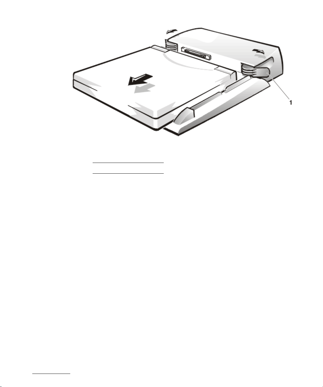
Figure 2. Port Replicator
Release handles
1
5. Remove the main battery from the battery compartment (see Figure 3).
Unlock the latch lock on the bottom of the computer by flipping it toward the back
of the computer. Slide the latch release in the direction of the arrow. Keep holding
the latch release with one hand while pulling the battery out of the compartment
with the other.
support.dell.com Removing and Replacing Parts 3

Figure 3. Battery Compartment
Latch lock (unlocked position)
1
Batter y
2
Latch release
3
6. Remove PC Cards (see Figure 4).
NOTICE: Use the PC Card configuration utility on the taskbar to select
and stop a card before removing it from the computer. If you do not
remove the card in the configuration utility, you could lose data from
open application programs.
To remove PC Cards from the top connector, press the top eject button. When
the button slides out, press it again to release the card. Gently remove the card.
Press the eject button again until it is flush with the computer casing. Grasp the
end of the card, and pull it completely from the slot.
To remove PC Cards from the bottom connector, follow the same procedure.
4 Dell Inspiron 7500 — Removing and Replacing Parts
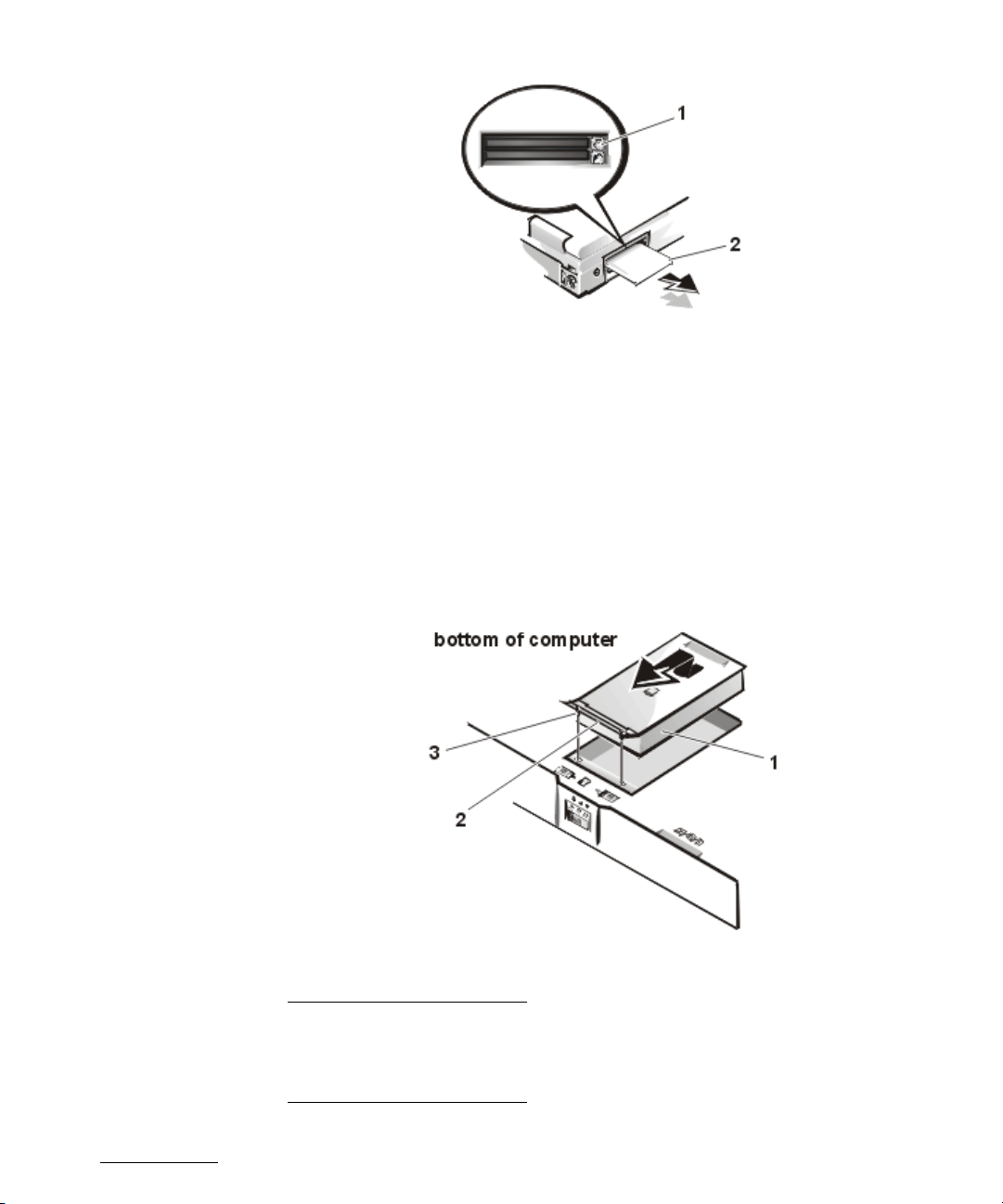
Figure 4. PC Card Removal
7. Remove the hard-disk drive assembly (see Figure 5).
Loosen the two captive screws that secure the hard-disk drive into the bottom of
the computer. The front edge of the cover pops up slightly. Slide the hard-disk
drive toward the front of the computer and then lift the drive out of the computer.
NOTICE: When the hard-disk drive is not in the computer, store it in a
hard-disk drive case to protect it from exposure to static electricity.
NOTICE: Handle the hard-disk drive gently and don’t bump or drop the
drive. Rough handling of the drive could induce failure or loss of data.
Figure 5. Hard-Disk Drive Assembly Removal
Hard-disk drive
1
Hinge
2
Captive screws (2)
3
support.dell.com Removing and Replacing Parts 5
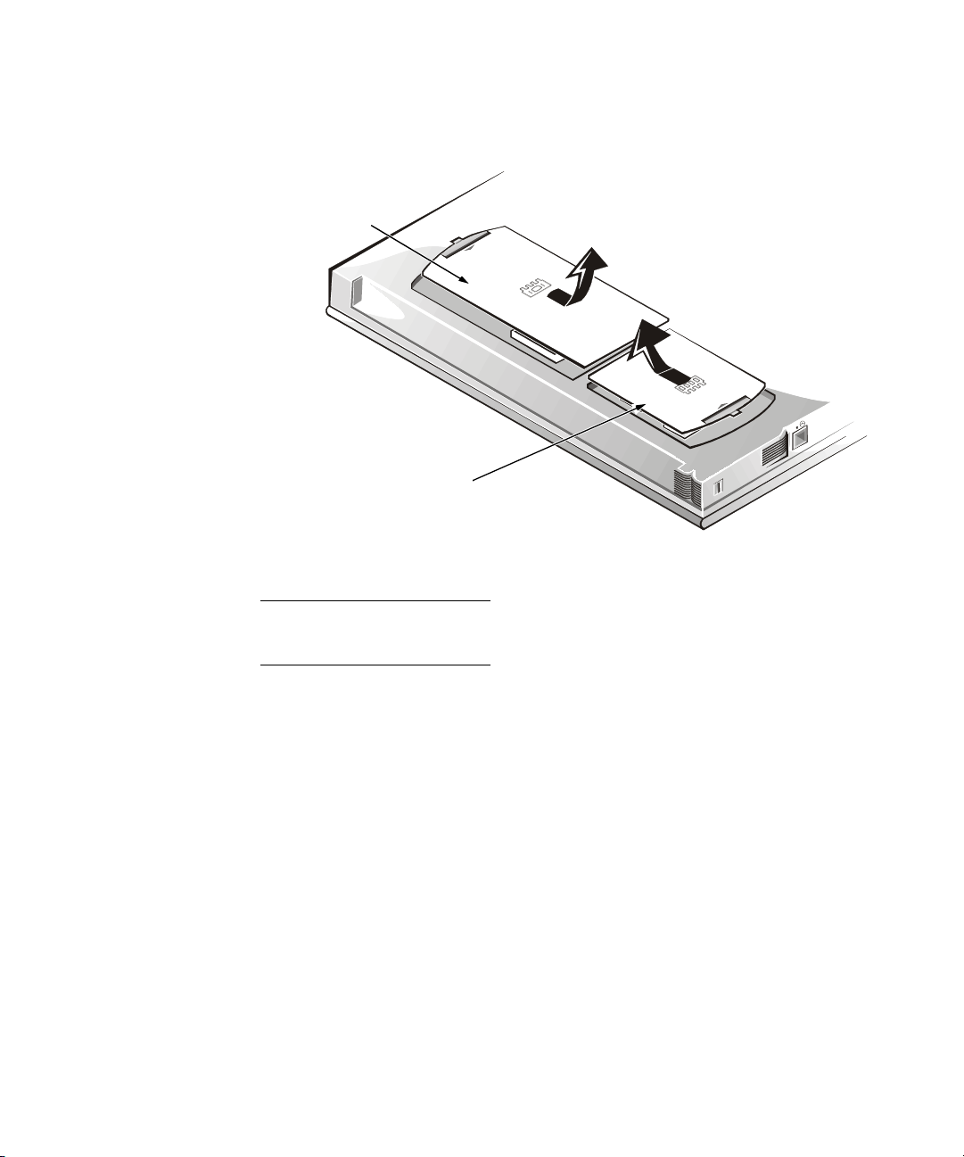
8. Remove the memory module covers (see Figure 6).
Slide the memory module cover as far as it will go in the direction of the arrow,
and then remove the cover.
1
bottom of computer
2
Figure 6. Memory Module Covers
Video card cover
1
Memory module cover
2
To replace a cover, place it over the opening, leaving a small gap along the
rounded edge, and then slide the cover toward the outside of the computer until
it snaps into place.
9. Remove the memory modules (see Figure 7).
Carefully spread apart the inner metal tabs of the memory module socket to disengage the module from the socket. The module should pop up slightly. Then pull
the memory module out of the socket.
6 Dell Inspiron 7500 — Removing and Replacing Parts
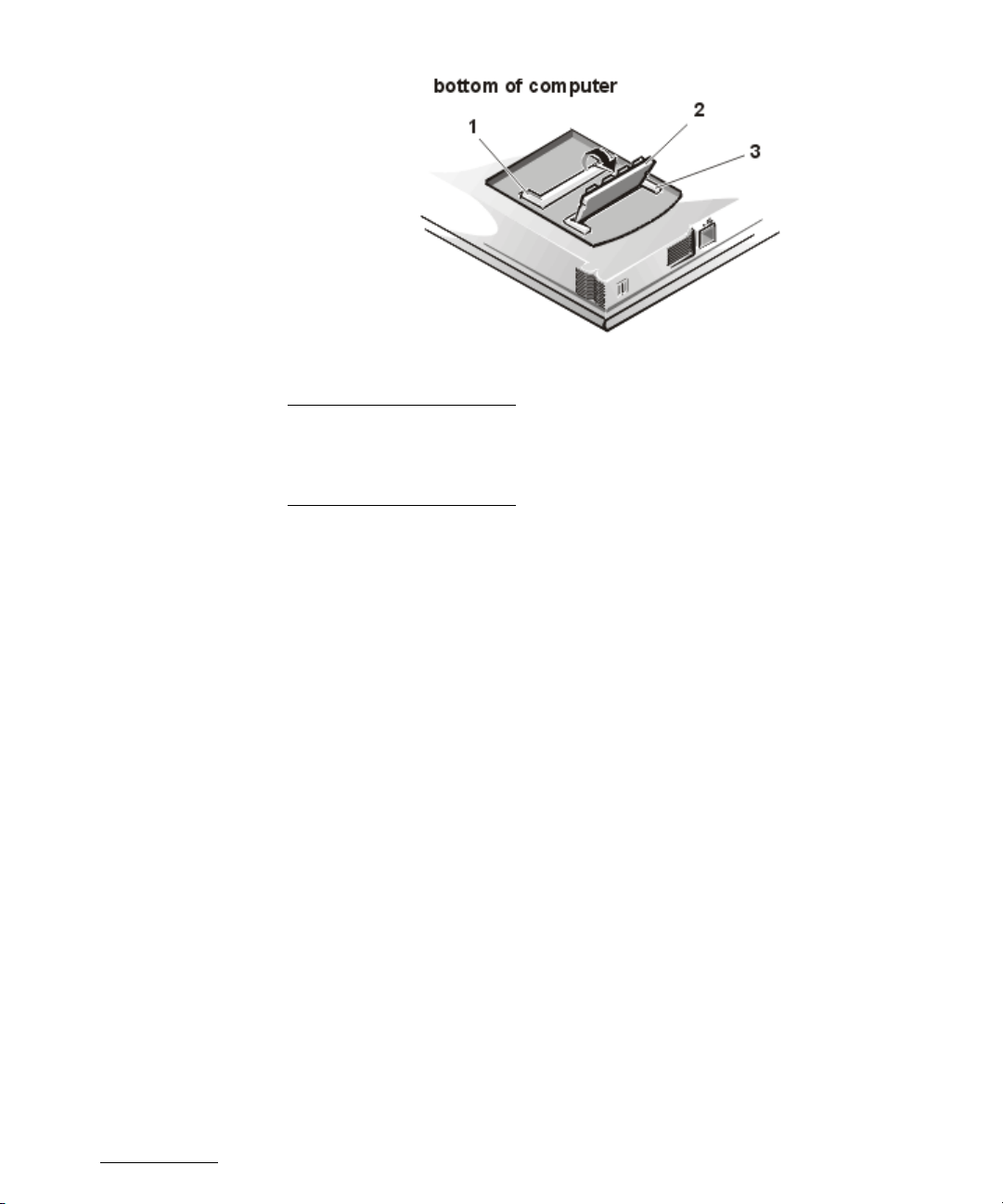
Figure 7. Memory Modules
Slot 1
1
Memory module
2
Slot 2
3
support.dell.com Removing and Replacing Parts 7
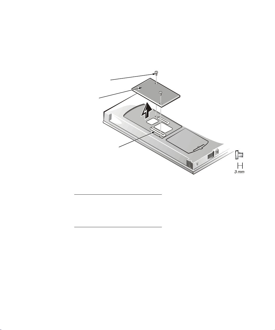
10. Remove the video card (see Figure 8).
Remove the two 3-mm screws securing the video card. Gently pull the video card
off of the connectors on the bottom of the system board by lifting it at the
notches located between the screws. Do not rock the card to remove it because
this may damage the connectors.
Inspect the two thermal pads on the bottom of the system board and replace
them if necessary.
1
2
bottom of computer
3
Figure 8. Video Card Removal
3-mm screws (2)
1
Video card
2
Video card
3
connectors (2)
8 Dell Inspiron 7500 — Removing and Replacing Parts
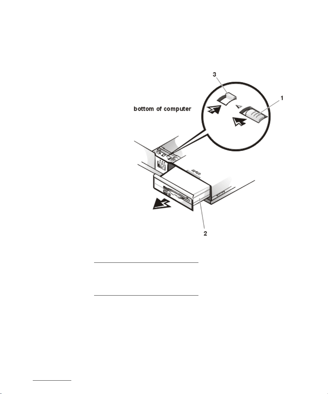
11. If present, remove the module from the MegaBay™ (see Figure 9).
Unlock the latch lock by flipping it toward the back of the computer. Slide the latch
release in the direction of the arrow. Keep holding the latch release with one hand
while pulling the combo module or second battery straight out of the MegaBay
with the other.
Figure 9. Media Bay Module Removal
Latch release
1
Media bay module
2
Latch lock (unlocked position)
3
Recommended Tools
NOTICE: Only a certified service technician should perform the following
procedures for removing and replacing parts. The warranty on the computer becomes void if anyone other than a certified technician performs
these procedures.
support.dell.com Removing and Replacing Parts 9

Most of the procedures require the use of one or more of the following tools:
• Small flat-blade screwdriver
• Number 1 Phillips-head screwdriver
• Antistatic grounding strap
• Dental pick
• Small scribe or nylon flat blade
• Nut drivers (5 mm and 5.5 mm)
Screw Identification and Tightening
NOTICE: The correct-length screw must be used when reinstalling a screw.
Otherwise, hardware damage could result. Make sure that the screw is
properly aligned with its corresponding hole, and avoid overtightening.
NOTICE: During the removal and replacement procedures, you will see
Kapton tape in many places on the computer. When reinstalling or replacing parts, be sure to replace the Kapton tape correctly to retain the
electrical protection and noise reduction the tape provides.
Be careful not to scratch the computer plastic case by allowing screws to get
between the disassembly surface and the plastic case. Dell suggests a soft padded
work surface.
The Inspiron 7500 contains many screws of various sizes. To help keep track of the
screws, use a tackle or pill box as a storage device. Use Table 1 as a location template
to store the screws during disassembly.
10 Dell Inspiron 7500 — Removing and Replacing Parts

Table 1. Screw Identification and Location
Hard-disk drive Combo module Keyboard LCD panel (15-inch) XGA
4X K-head M3x3L 2X K-head, M2x2.5L
3X K-head, M2.5x3L
8X K-head M2x3L
LCD panel (15-inch)
SXGA+
8X 3319U SCR, M2x3,
KSH, MSCR, CPS, LKG
2X 7043E SCR,
M2.5x.45+10FP-ZK, NL
Front bezel Palmrest assembly IR board Hard-disk drive heat shield
4X binding head, M2.5x6L 4X binding head,
Touch pad assembly Speakers PC Card heat sink Heat exchanger/fan
4X K-head M2.5x4L
3X K-head M2.5x4L
Processor board Hinge saddles Left hinge saddle Right hinge saddle
3X binding head, M2x5L 1X binding head,
LCD panel (15.4-inch)
SXGA
2X 0300U SCR, 2.5x8,
KSH, MSCR, CPS
8X 9200U SCR, M2x4,
KSH, MSCR, CPS
M2.5x6L
6X K-head, M2.5x4L
1X K-head, M2.5x4L
5X K-head M2.5x4L 2X K-head, M2.5x4L 2X binding head, M2x5L
M2.5x6L
4X pan head,
M2.5x20L
Thermal shield Display assembly
1X K-head, M2.5x4L
4X flat head, M2x4L
2X K-head M2.5x4L 5X K-head M2.5x4L
4X K-head, M2.5x4L
1X binding head,
M2.5x10L
1X pan head,
M2.5x20L
1X 0143E SCR,
M2.5x.45P+3FP-ZK
2X 7043E SCR,
M2.5x.45+10FP-ZK-NL
6X 8043E SCR, 2.5x.45+6PZK-NL
4X binding head, M2.5x6L
4X K-head, M2.5x4L
1X pan head, M2.5x20L
1X binding head M2.5x10L
RJ-11 card System board PC Card cage Audio thermal shield
1X K-head, M2.5x4L 3X K-head, M2.5x4L 1X K-head, M2.5x4L
4X pan head,
M2x18L
Latch assembly
1X K-head, M2.5x4L
2X K-head, M2.5x4L
support.dell.com Removing and Replacing Parts 11
1X binding head, M2.5x10L